1
OPERATOR'S MANUAL
MANUEL de L'UTILISATEUR
MANUAL del OPERADOR
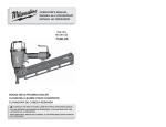
Cat. No.
No de cat.
7100-20
ROUND HEAD FRAMING NAILER
CLOUEUSE À BANDE POUR CHARPENTE
CLAVADORA DE CABEZA REDONDA
TO REDUCE THE RISK OF INJURY, USER MUST READ OPERATOR'S MANUAL.
AFIN DE RÉDUIRE LES RISQUES DE BLESSURES, L’UTILISATEUR DOIT LIRE
LE MANUEL DE L’OPÉRATEUR.
PARA REDUCIR EL RIESGO DE LESIONES, EL USUARIO DEBE LEER EL MANUAL
DEL OPERADOR.
GENERAL SAFETY INSTRUCTIONS
DANGER
IMPORTANT SAFETY INSTRUCTIONS. SAVE THESE
INSTRUCTIONS PERTAINING TO A RISK OF INJURY OR DEATH
WARNING
WHEN USING TOOLS, BASIC PRECAUTIONS SHOULD
ALWAYS BE FOLLOWED, INCLUDING THE FOLLOWING:
GENERAL
1.
PERSONAL SAFETY
To reduce the risk of injury, read all
instructions before using the tool.
7.
WORK AREA
2.
3.
4.
5.
6.
Keep the work area clean and well
lighted. Cluttered benches and dark
areas increase the risk of injury.
8.
Do not operate the tool in explosive
atmospheres, such as in the presence
of flammable liquids, gases, or dust.
The tool is able to create sparks resulting
in the ignition of the dust or fumes.
Keep bystanders, children, and visitors away while operating the tool.
Distractions are able to result in the loss
of control of the tool.
9.
Know what is behind your workpiece.
A fastener could travel through the workpiece and out the other side, striking a
bystander and causing serious injury.
Stay alert. Watch what you are doing
and use common sense when operating
the tool. Do not use the tool while tired
or under the influence of drugs, alcohol,
or medication. A moment of inattention
while operating the tool increases the
risk of injury to persons.
Dress properly. Do not wear loose
clothing or jewelry. Contain long hair.
Keep hair, clothing, and gloves away
from moving parts. Loose clothes,
jewelry, or long hair increases the risk
of injury to persons as a result of being
caught in moving parts.
Avoid unintentional starting. Remove
finger from the trigger when not driving fasteners. Be sure the trigger is not
pulled before connecting to the air supply. Do not carry the tool with your finger
on the trigger or connect the tool to the
air supply with the trigger pulled.
10. Do not overreach. Keep proper footing
and balance at all times. Proper footing
and balance enables better control of
the tool in unexpected situations.
DANGER: Avoid performing operations where the fastener may contact
hidden wiring. Contact with a “live”
wire will make exposed metal parts of
the tool “live” and shock the operator,
resulting in serious injury or death.
Contact a qualified electrician to ensure
a safe work environment exists.
11. Use safety equipment. A dust mask,
non-skid safety shoes and a hard hat
used for appropriate conditions will reduce
personal injuries.
12. The operator and other people in the
work area must wear eye protection
in accordance with ANSI Z87.1. Eye
protection does not fit all operators in the
same way. Make sure the eye protection
chosen has side shields or provides
protection from flying debris both from
the front and sides. The employer is
responsible for enforcing the use of eye
protection by the operator and other
people in the work area. When required,
wear head protection in accordance with
ANSI Z89.1.
contact or leaving work area. Verify the
tool is empty and there is no residual pressure in the tool prior to performing these
actions. Such precautionary measures
reduce the risk of injury to persons.
21. Store idle tools out of reach of children and other untrained persons.
A tool is dangerous in the hands of
untrained users.
22. Maintain the tool with care. A properly
maintained tool reduces the risk of injury.
If the tool has been dropped, received a
sharp blow, been run over, etc., perform
the "Required Daily Testing" before
further use.
13. Always wear ear protectors when
using the tool for extended periods.
Prolonged exposure to high intensity
noise is able to cause hearing loss.
23. Check for misalignment or binding
of moving parts, breakage of parts,
and any other condition that affects
the tool’s operation. If damaged, have
the tool serviced before using. Many accidents are caused by poorly maintained
tools. There is an increased risk of the
tool bursting if the tool is damaged.
14. Do not carry an air hose or a tool connected to an air hose when climbing
ladders, rigging or scaffolding. Do
not attach an air hose or tool connected to an air hose to your body
when working at elevated heights. Attach the hose to the structure to reduce
the risk of loss of balance and injury if
the hose shifts.
24. Use only those fasteners specifically
recommended. Fasteners not identified
for use with this tool by the tool manufacturer are able to result in a risk of injury
to persons or tool damage when used
in this tool. See the "Specifications"
section for fastener requirements.
15. Always assume that the tool contains
fasteners. Do not point the tool toward
yourself or anyone whether it contains
fasteners or not.
16. Do not nail on top of another nail. This
can cause the nail to be deflected and
hit someone, or cause the tool to react
and result in a risk of injury to persons.
25. Use only accessories that are identified by the manufacturer for the specific tool model. Use of an accessory
not intended for use with the specific
tool model, increases the risk of injury
to persons.
TOOL USE AND CARE
SERVICE
17. Use clamps or another practical way
to secure and support the workpiece
to a stable platform. Holding the work
by hand or against the body is unstable
and is able to lead to loss of control.
26. a) Tool service must be performed
only by qualified repair personnel.
b) The wrench provided is for tightening screws during "Required Daily
Testing".
18. Do not force the tool. Use the correct
tool for the application. The correct tool
will do the job better and safer at the rate
for which the tool is designed.
c) Use only identical replacement
parts recommended by the manufacturer.
19. Do not use the tool if the trigger does
not turn the tool on or off. Any tool that
cannot be controlled with the trigger is
dangerous and must be repaired.
27. Use only the air tool lubricants supplied
with the tool or specified by the manufacturer. Do not use other lubricants;
they will damage the tool. See "Accessories" for a list of recommended air tool
lubricants.
20. Disconnect the tool from the air source,
then empty the magazine before making
adjustments, doing tool maintenance,
clearing jams, touching the workpiece
2
3
TERMINOLOGY
AIR SOURCE
tool or serious injury to persons. Use
only clean, dry, regulated compressed
air at the rated pressure or within the
rated pressure range as marked on the
tool. Prior to using the tool, always verify
that the air source has been adjusted to
the rated air pressure or within the rated
air-pressure range. Air compressors
should comply with ANSI B19.3.
28. DANGER: Do not use oxygen, combustible gases or bottled gases as a
power source for this tool. The tool will
explode and cause death or serious
injury.
29. Never connect to an air source that
is capable of exceeding 200 psi. Over
pressurizing the tool may result in bursting, abnormal operation, breakage of the
Actuate
Fastener
To cause movement of the tool component(s)
intended to drive a fastener.
A staple, pin, brad, nail, or other fastening
device which is designed and manufactured
for use in the tools.
Actuation System
•
SPECIFIC SAFETY INSTRUCTIONS
1.
Use air supply hoses with a minimum
working pressure rating of 200 psi.
2.
Use pressure regulators to limit the
air pressure supplied to the tool. Set
the regulators to no more than 120
psi.
3.
4.
5.
6.
7.
Install only hose couplings that will
allow all pressure to be removed from
tool when disconnected from the
source. If the wrong fitting is installed,
pressure may remain in the tool after
disconnection, allowing it to drive a
fastener, possibly causing injury.
8.
Do not remove, tamper with, or
otherwise cause the tool operating
controls to become inoperable. This
will cause unexpected actuation, resulting in serious injury.
9.
Do not operate a tool if any portion of
the tool operating controls is inoperable, disconnected, altered, or not working properly. This will cause unexpected
actuation, resulting in serious injury.
10. Always keep hands and body away
from discharge area of the tool. Never
attempt to clear a jammed workpiece
contact by grasping the discharge area
of the tool. Fasteners discharged from
tool can cause serious injury if they
contact hands or body.
Prior to each use, check workpiece
contact and trigger for correct operation. Do not disassemble or clamp
parts of the workpiece contact, trigger,
or driving mechanism. This will cause
unexpected actuation, resulting in serious injury.
Jam
The use of a trigger, workpiece contact
and/or other operating control, separately
or in some combination or sequence, to
actuate the tool.
•
An obstruction in the feed or drive areas of
the tool.
Single sequential actuation
Workpiece Contact
An actuation system that requires the
workpiece contact and then the trigger
to be activated in a specific sequence
to drive a fastener. Additional actuation
can occur when the trigger is released
and reactivated.
An operating control element on the tool
intended to be activated by the workpiece
to be fastened.
Contact actuation
An actuation system that requires the
workpiece contact and the trigger to be
activated in any sequence to drive a
fastener. Additional actuation can occur
when either the workpiece contact or the
trigger is released and reactivated.
•
Selective actuation
An actuation system that allows selection of actuation systems: single sequential actuation or contact actuation.
11. Do not drive fasteners close to the
edge of the workpiece. Fasteners can
slip off corners and edges or penetrate
through thin material, making them
projectiles capable of causing serious
injury.
Never point the discharge area of the
tool at any body parts or at other people. Always assume the tool is loaded
and capable of driving a fastener.
Symbology
12. Use the tool only for the intended
purpose. Do not abuse the tool. Do
not use as a hammer, stamp or engrave
information onto parts, drop or impact
the tool or otherwise apply excess force
to the tool in use. Do not mount the
tool to stands or modify it for stationary
use.
Do not actuate the tool into free
space. Do not engage in horseplay.
The discharged fasteners are projectiles
capable of causing serious injury.
When using the tool, ensure the
workpiece contact is securely placed
on the workpiece. Hold the tool firmly
and be prepared for the recoil.
Read the Operator's Manual
Wear Eye Protection
Keep hands away
13. Do not carry tool by the air hose. Only
carry the tool by the handle with your
finger off of the trigger.
14. Do not use this tool without the
safety warning label in place. If the
label is damaged or missing, contact
MILWAUKEE for a free replacement.
4
Specifications
Cat.
No.
Operating
Pressure
Fastener
Length
7100-20
min. 70 PSI
max. 120 PSI
min. 2"
max. 3.5"
Air
Collation Fastener Size
(Diameter) Consumption
Angle
min. .113"
max. .148"
22°
5
Air
Inlet
Magazine
Capacity
.16 ft3/cycle at 3/8 in. 64-72 nails
100 psi
NPT
ASSEMBLY
FUNCTIONAL DESCRIPTION
5
WARNING
8
Disconnect the air supply from the
tool and remove fastener strips
before changing or removing accessories. Only use accessories specifically recommended for this tool
by the manufacturer. Others may be
hazardous.
6
7
9
Removing and Installing the Rafter Hook
10
Fig. 1
End cap
3
16
2
1
15
14
1.
No-mar pad
2.
Toe-nail claw
3.
Workpiece contact
4.
Depth of drive adjustment
5.
Exhaust deflector
6.
Actuation selector
7.
Trigger
8.
Rafter hook
9.
Air inlet
12
10. Nameplate (on top of magazine)
11. Nail stop tab
12. Extra no-mar pad storage
(on back of magazine)
13. Warning label (on top of magazine)
14. Pusher
15. Pusher release button
1.
Rotate the hook until it snaps into one of
the preset positions.
2.
Remove the two mounting screws using
the wrench provided.
No-Mar Pad
3.
Pull the hook off the rear of the tool.
The No-Mar Pad on the nose of the tool
protects the workpiece when the workpiece
contact is compressed during actuation. The
pad can be removed and replaced.
1. Before removing or replacing no-mar
pads, disconnect the air supply from the
tool and remove fastener strips.
2. To remove the pad, pull the pad open
and away from the toe-nailing claw.
3. Storage for an additional pad is available
on the magazine of the tool.
4. To replace the pad, fit it into place over
the points of the claw.
To install the hook:
Exhaust
The exhaust cap can be adjusted to direct
the exhaust as desired. Turn the exhaust cap
to the desired locking position.
16. Nail guide
6
Screw
(2)
To remove the hook:
11
4
Rafter hook
Air
inlet
The operator and other people in the
work area must wear eye protection
in accordance with ANSI Z87.1. Eye
protection does not fit all operators
in the same way. Make sure the eye
protection chosen has side shields or
provides protection from flying debris
both from the front and sides.
13
Front of tool
7
1.
Align the spring-loaded post on the hook
with a slot on the rear of the tool.
2.
Slide the hook onto the tool, making sure
the hook points toward the front of the
tool. Push the hook up against the end
cap.
3.
Install the two mounting screws using
the wrench provided. Tighten securely.
4.
Verify that the hook is installed correctly
by firmly pulling the hook toward the air
inlet. It must not move.
Connecting the Air Supply
Lubricating the Tool
Lubricate the tool with air tool lubricant
before connecting the air supply. Under low
use, lubricate once a day. Under heavy use,
lubricate twice a day. Use only a few drops
of oil at a time. Using too much oil will cause
it to collect in the tool and be noticeable
in the exhaust. Do not use detergent oil,
WD-40, transmission fluid, motor oil, or other
lubricants not specifically designated as air
tool lubricant. These lubricants will cause
accelerated wear to the seals, o-rings and
bumpers in the tool, resulting in poor tool
performance and frequent maintenance.
Fig. 2
DANGER
WARNING
Do not use oxygen, combustible gases or bottled gases as a power source
for this tool. The tool will explode and
cause death or serious injury.
WARNING
Always use a coupling that discharges all the compressed air in the tool at
the time the fitting or hose coupling is
disconnected. Using a coupling that
does not discharge the compressed
air could cause unintended operation
and serious injury.
3/8" NPT quick
connector
To connect the air supply:
1.
Remove the plastic plug from the tool air
inlet.
2.
Insert a 3/8" NPT quick connector into
the tool air inlet.
NOTE: To improve the seal between
the connector and the tool, and to help
protect against oxidation, apply a PTFE
tape or paste to the connector threads
before insertion.
8
3.
Lubricate the quick connector with 2-3
drops air tool lubricant.
4.
Snap the air hose onto the quick connector.
5.
Check for air leakage.
WARNING
Always point the tool away from
yourself and others when installing
fasteners. Failure to do so could
result in injury.
To avoid serious injury, disconnect
the tool from the air supply before
removing fastener strips or clearing
a jammed fastener.
Always make sure the tool's magazine is EMPTY before connecting to
the air supply. The tool may actuate
when the tool is first connected to the
air supply. Always connect the tool
to the air supply before loading nails
to prevent injury from unintended
actuation.
Keep fingers clear of fastener track
of magazine. Pusher could pinch
fingers, causing injury.
1.
Never install fasteners with the
workpiece contact or trigger activated. Failure to do so could result
in injury.
Use only clean, dry compressed air with a
maximum pressure of 200 psi. Before connecting the tool to the air supply, check the
air compressor regulator gauge to be sure it
is functioning properly, with a range between
70-120 psi. Air pressure higher than 120 psi
could cause injury and property damage. The
correct pressure is the lowest pressure that
will do the job.
2-3
drops of
air tool
lubricant
Removing Fastener Strips
Installing Fastener Strips
Use only recommended fasteners
of the correct size, length, collation
angle and head type, as indicated
on the tool's nameplate. Refer to the
"Accessories" section for information on recommended fasteners.
Other fasteners could result in tool
malfunction, leading to injury.
1.
2.
3.
4.
5.
Verify that the magazine is empty and
then connect the air supply to the tool.
Lay the tool on its side and point the
nose of the tool away from yourself and
others.
Feed fastener strips into the magazine and
over the nail stop tab. Be sure the point of
the fasteners is pointed downward.
NOTE: Use only recommended fasteners of the correct size, length, collation
angle and head type as indicated on the
tool's nameplate.
Slide the pusher to the rear of the magazine and over the nail stop tab.
Gently allow the pusher to slide forward,
pushing the fasteners toward the driving
mechanism. The pusher will stop when
it rests against the end of the fastener
strip.
NOTE: The fasteners must be aligned
with the nose of the tool for the fasteners
to be installed correctly.
9
Lay the tool on its side and point the
nose of the tool away from yourself and
others.
2.
Disconnect the air supply from the tool.
3.
To remove fasteners, press the pusher
release button on the pusher and gently
slide the pusher forward toward the driving
mechanism.
4.
Slide the nails back until they stop.
5.
Press down on the fastener stop tab
near the end of the magazine and slide
the fasteners over the tab.
6.
Remove fastener strip from the tool.
7.
Reload according to "Installing Fastener
Strips".
Clearing a Jammed Fastener
OPERATION
Most jams are caused by a fastener or part
of a fastener wedging between the driver
blade and the nail guide. Fastener strips
with an incorrect collation angle or the
wrong fastener type (such as clipped head
fasteners) may cause continuous jamming.
To clear the jam:
1.
WARNING
The operator and other people in the
work area must wear eye protection
in accordance with ANSI Z87.1. Eye
protection does not fit all operators
in the same way. Make sure the eye
protection chosen has side shields or
provides protection from flying debris
both from the front and sides. The
employer is responsible for enforcing
the use of eye protection by the operator and other people in the work area.
When required, wear head protection
in accordance with ANSI Z89.1.
Lay the tool on its side and point the
nose of the tool away from yourself and
others.
2.
Disconnect the air supply from the tool
and remove fastener strip.
3.
Insert a screwdriver into the end of the
nail guide. The tip of the screwdriver
should contact the tip of the driver
blade.
4.
Tap the screwdriver gently with a hammer. The screwdriver will push the driver
blade back, freeing the jam.
5.
Remove the fastener and other debris
(use needle-nose pliers if necessary).
6.
Follow the steps under "Required Daily
Testing" before restarting the work.
WARNING
To reduce the risk of injury to yourself and others, test the tool before
beginning work each day according to
the "Required Daily Testing" section.
Do not use the tool unless you thoroughly understand the actuation
operation selected.
Disconnect the air supply from the
tool and remove fastener strips
before leaving the work area, moving the tool to another location, or
handing the tool to another person.
Failure to do so could result in serious injury.
Selecting Actuation Mode
The selectable trigger can be set to either
Single Sequential Actuation mode or Contact
Actuation mode.
Do not carry an air hose or a tool connected to an air hose when climbing
ladders, rigging or scaffolding. Do
not attach an air hose or tool connected to an air hose to your body
when working at elevated heights.
Attach the hose to the structure to
reduce the risk of loss of balance and
injury if the hose shifts.
Fig. 4
Fig. 3
Single
Sequential
Actuation
Tap screwdriver
to free fastener
Single Sequential Actuation Operation
1. Grip the handle firmly.
2. Position the nose of the tool on the work
surface.
3. Push the tool against the work surface,
compressing the workpiece contact.
4. Pull the trigger to drive the fastener. The
tool will recoil away from the workpiece
as the fastener is driven.
5. Remove your finger from the trigger and
remove the tool from the workpiece.
NOTE: If the tool is not removed from
the workpiece, another fastener may be
driven if the trigger is pulled again.
Fig. 5
Contact
Actuation
1.
Push in and hold the Actuation
Selector.
2.
Rotate the Selector to Single Sequential Actuation (T) or Contact Actuation
(TTT).
3.
Release the Actuation Selector.
NOTE: Be sure the selector is snapped
into position. Understand the actuation
process before use.
10
11
Contact Actuation Operation
1. Grip the handle firmly.
2. Pull and hold the trigger.
3. Push the tool against the work surface,
compressing the workpiece contact to
drive the fastener. The tool will recoil
away from the workpiece as the fastener
is driven.
Setting the Air Pressure and Depth of
Drive
NOTE: Contact Actuation will also work by
first compressing the workpiece contact, then
pulling the trigger.
Know what is behind your workpiece.
A fastener could travel through the
workpiece and out the other side,
striking a bystander and causing serious injury. Lower the air pressure
and/or depth of drive to prevent the
fastener from being pushed all the
way through the workpiece.
7.
The amount of air pressure required will
depend on the size of the fastener and the
workpiece material.
WARNING
Reload Indicator
To indicate that the magazine is almost
empty of fasteners (about 4-5 left), the workpiece contact will not compress, preventing
operation under usual pressure. Install more
fasteners to continue working.
WARNING
NEVER wedge or hold back the workpiece contact mechanism during
operation of the tool. Never attempt
to clear a jammed workpiece contact
by grasping the discharge area of the
tool. Doing so could result in serious
injury.
Lay the tool on its side and point the
nose of the tool away from yourself and
others.
2.
Disconnect the air supply from the tool
and remove fastener strip.
3.
Set the depth of drive adjustment to the
middle of its range.
4.
Reload fastener strip according to "Installing Fastener Strips".
Always point tool away from yourself
and others.
5.
6.
Begin testing the depth of drive by driving a test fastener into the same type of
workpiece material used for the actual
job using an air pressure of 90-95 psi.
Raise or lower the air pressure to find the
lowest setting that will drive the fastener
consistently. Do not exceed 120 psi.
NOTE: It may be possible to achieve the
desired depth with air pressure adjustments alone. If finer adjustments are
needed, use the depth of drive adjustment.
12
Reload fastener strip according to "Installing Fastener Strips".
9.
Drive a test fastener and repeat step 7
and 8 until desired depth is reached.
WARNING
1.
Set to
middle of
range
8.
REQUIRED DAILY TESTING
To reduce the risk of injury to yourself and others, test the tool before
beginning work each day or if the
tool is dropped, received a sharp
blow, been run over, etc. Complete
the following checklist IN ORDER. If
the tool does not work as it should,
contact a MILWAUKEE service facility immediately.
Fig. 6
To avoid serious injury, do not attempt
to prevent the recoil by holding the
tool too firmly against the work. Keep
face and body away from the tool.
During normal use, the tool will recoil
immediately after driving a fastener.
This is a normal function of the tool.
Restriction to the recoil can result
in a second fastener being driven
when the tool is in Contact Actuation
mode. Grip the handle firmly, let the
tool do the work, and do not place
a second hand on top of the tool or
near exhaust.
To fine-tune the depth of drive, disconnect the air supply and lay the tool on
its side and point the nose of the tool
away from yourself and others. Remove
fastener strip. Turn the depth selector
left or right to increase or decrease the
driving depth.
1.
Disconnect the air supply from the tool
and remove fastener strip.
2.
Check all screws, bolts, nuts, and pins
on the tool. Any loose fasteners must be
tightened.
Holding the workpiece contact away
from the workpiece, pull back the
fastener pusher on the magazine (to
override the Reload Indicator). Pull and
hold the trigger for 5 seconds. The tool
must not operate.
Continue to pull and hold the trigger and
push the workpiece contact against a
workpiece. The tool must not operate.
Without pulling the trigger, pull back
the fastener pusher on the magazine
(to override the Reload Indicator) and
press the workpiece contact against a
workpiece. Pull the trigger. The tool must
operate.
Release the trigger. The driver must
move up.
7.
Select the Contact Actuation Operation.
3.
Pull back the fastener pusher on the
magazine (to override the Reload Indicator) and press the workpiece contact
against a workpiece. It must move
smoothly.
Holding the workpiece contact away
from the workpiece, pull back the
fastener pusher on the magazine (to
override the Reload Indicator) and pull
the trigger. The tool must not operate.
4.
With the workpiece contact pressed
against the workpiece, pull the trigger.
It must move smoothly.
Continue to pull and hold the trigger and
push the workpiece contact against a
workpiece. The tool must operate.
5.
Connect the air supply (at 70 psi) to the
tool. DO NOT load a fastener strip.
8.
6.
Select the Single Sequential Actuation
Operation. Air must not leak from the
tool.
If all previous tests work properly, set the
tool for your work. Select the operation
and load fastener strips.
9.
Set the depth of drive according to the
"Setting the Air Pressure and Depth of
Drive" section.
Without pulling the trigger, pull back
the fastener pusher on the magazine
(to override the Reload Indicator) and
press the workpiece contact against a
workpiece. The tool must not operate.
10. If all tests operate properly, the tool is
ready for use. Repeat these tests before
use each day or if the tool is dropped,
received a sharp blow, been run over,
jammed, etc.
13
MAINTENANCE
WARNING
Cold Weather Operation
For cold weather operation, near and below
freezing, the moisture in the air line may
freeze and prevent tool operation. Use an
air tool lubricant or permanent antifreeze as
a cold weather lubricant in the air line.
To reduce the risk of injury, use only
identical replacement parts recommended by the manufacturer. Tool
service must be performed only by
qualified repair personnel. Always
wear safety goggles or glasses with
side shields when servicing tools.
Disconnect tool from air supply before servicing.
Do not store tools in a below-freezing environment. Ice or frost could form on the tools'
operating valves and mechanisms, causing
tool failure.
Cleaning
Air Supply-Pressure and Volume
Clean dust and debris from tool vents.
Keep tool handles clean, dry and free of oil
or grease. Use only mild soap and a damp
cloth to clean the tool, since certain cleaning
agents and solvents are harmful to plastics
and other parts. Some of these include gasoline, turpentine, lacquer thinner, paint thinner,
chlorinated cleaning solvents, ammonia and
household detergents containing ammonia.
Never use flammable or combustible solvents around tools.
Air volume is as important as air pressure.
The air volume supplied to the tool may be inadequate because of undersized fittings and
hoses, or from the effects of dirt and water in
the system. Restricted air flow will prevent
the tool from receiving an adequate volume
of air, even though the pressure reading is
high. The results will be slow operation or
reduced driving power. Before evaluating tool
problems for these symptoms, trace the air
supply from the tool to the supply source for
restrictive connectors, low points containing
water and anything else that would prevent
full volume flow of air to the tool.
Lubrication
Frequent, but not excessive, lubrication is
required for best performance. Oil added
through the air line connection will lubricate
the internal parts. Do not use detergent oil,
WD-40, transmission fluid, motor oil, or other
lubricants not specifically designated as air
tool lubricant. These lubricants will cause
accelerated wear to the seals, o-rings and
bumpers in the tool, resulting in poor tool
performance and frequent maintenance.
FIVE YEAR TOOL
LIMITED WARRANTY
ACCESSORIES
WARNING
Every MILWAUKEE tool is tested before leaving
the factory and is warranted to be free from defects
in material and workmanship. MILWAUKEE will
repair or replace (at MILWAUKEE’s discretion),
without charge, any tool (including battery chargers) which examination proves to be defective
in material or workmanship for five (5) years after
the date of purchase. Return the tool and a copy
of the purchase receipt or other proof of purchase
to a MILWAUKEE Factory Service/Sales Support
Branch location or MILWAUKEE Authorized
Service Station, freight prepaid and insured. This
warranty does not cover damage from repairs
made or attempted by other than MILWAUKEE
authorized personnel, misuse, alterations, abuse,
normal wear and tear, lack of maintenance, or accidents. Certain parts of certain tools, such as but
not limited to o-rings, seals, bumpers, and driver
blades for MILWAUKEE nailers and stapling tools,
are considered normal wear and tear items not
covered by this warranty.
Always disconnect the air supply
from the tool and remove fastener
strips before changing or removing
accessories. Only use accessories
specifically recommended for this
tool. Others may be hazardous.
For a complete listing of accessories refer to
your MILWAUKEE Electric Tool catalog or go
on-line to www.milwaukeetool.com. To obtain
a catalog, contact your local distributor or a
service center.
Use MILWAUKEE fasteners with the
following specifications:
The warranty period for Li-Ion Battery Packs is two
(2) years from the date of purchase. The warranty
period for Ni-Cd Battery Packs, Flashlights, Radios,
and Professional Hoists (lever, chain, and electric)
is one (1) year from the date of purchase.
Length: 2" to 3.5"
Collation Angle: 22°
Size (diameter): 0.113" to 0.148"
THE REPAIR AND REPLACEMENT REMEDIES
DESCRIBED HEREIN ARE EXCLUSIVE. IN NO
EVENT SHALL MILWAUKEE BE LIABLE FOR ANY
INCIDENTAL, SPECIAL, OR CONSEQUENTIAL
DAMAGES OR FOR ANY EXPENSES, LOSSES
OR DELAYS INCIDENTAL TO ANY DAMAGE TO,
FAILURE OF, OR DEFECT IN ANY PRODUCT,
INCLUDING BUT NOT LIMITED TO LOSS OF
PROFITS.
Air Tool Oil
Synthetic formula for all season
performance
4 oz bottle
Cat. No. 49-32-7100
16 oz bottle
Cat. No. 49-32-7105
Quick Connectors
THIS WARRANTY IS EXCLUSIVE AND IN LIEU
OF ALL OTHER WARRANTIES, OR CONDITIONS,
WRITTEN OR ORAL, EXPRESS OR IMPLIED.
WITHOUT LIMITING THE GENERALITY OF
THE FOREGOING, MILWAUKEE DISCLAIMS
ANY IMPLIED WARRANTY OF MERCHANTABILITY OR FITNESS FOR A PARTICULAR
USE OR PURPOSE AND ALL OTHER IMPLIED
WARRANTIES.
This warranty gives you specific legal rights. You
may also have other rights that vary from state to
state and province to province. In those states that
do not allow the exclusion of implied warranties or
limitation of incidental or consequential damages,
the above limitations or exclusions may not apply
to you. This warranty applies to the United States,
Canada, and Mexico only.
14
15