1
REFRIGERATOR
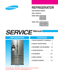
BOTTOM MOUNT FREEZER
BASIC : RFG298AA
MODEL NAME : RFG298AARS
RFG298AABP
RFG298AAWP
RFG298AAPN
MODEL CODE : RFG298AARS/XAA
RFG298AABP/XAA
RFG298AAWP/XAA
RFG298AAPN/XAA
REFRIGERATOR
CONTENTS
1. PRECAUTIONS(SAFETY WARNINGS) ·4
2. PRODUCT SPECIFICATIONS ·····8
3. DISASSEMBLY AND REASSEMBLY ·26
4. TROUBLESHOOTING ········52
5. EXPLODED VIEW & PARTS LIST ··101
6. PCB DIAGRAM ··········124
·········129
7. WIRING DIAGRAM·
8. SCHEMATIC DIAGRAM ······130
RFG298AA
For the latest parts information, Please access to our service web site
(● North America : http://service.samsungportal.com)
WARNING
IMPORTANT SAFETY NOTICE
The service guide is for service men with adequate backgrounds of
electrical, electronic, and mechanical experience. Any attempt to repair
a major appliance may result in personal injury and property damage.
The manufacturer or dealer cannot be responsible for the interpretation
of this information.
SAMSUNG ELECTRONICS AMERICA, INC.
Technical Service Guide
Copyright ⓒ2008
All rights reserved. This service guide may not be reproduced in whole or in
part in any form without written permission from the SAMSUNG ELECTRONICS
Company.
Contents
1. Precautions(Safety Warnings) ·····································4
2. Product Specifications ········································8
2-1) Introduction of main function ···································9
2-2) Specifications ·········································11
2-3) Interior Views ·········································12
2-4) Model Specification ·······································13
2-5) Model Specification &Specification Chart ·····························14
2-6) Dimensions of Refrigerator (Inches)································17
2-7) Optional Material Specification ··································18
2-8) Refrigerant Route in Refrigeration cycle ······························19
2-9) Cooling Air Circulation ·····································25
3. Disassembly and Reassembly ····································26
3-1) PRECAUTION ·········································27
3-2) Refrigerator Door ········································28
3-3) Door Handle Freezer ······································30
3-4) Refrigerator Light ········································31
3-5) Cover-display & water-dispenser ·································31
3-6) Water-dispenser ········································32
3-7) Glass Shelf ··········································33
3-8) Foldable Glass Shelf ······································34
3-9) Vegetable & Fruit Drawers Shelf ·································34
3-10) Cool Select Pantry·······································35
3-11) Water Tank ··········································36
3-12) Motor Damper ········································38
3-13) Water Filter (Disassembly) ···································38
3-14) Water Filter (Reassembly) ···································39
3-15) Gallon Door Bin ········································39
3-16) Vertical Hinged Section ····································40
3-17) Evaporator Cover In Refrigerator ································41
3-18) Evaporator In Refrigerator ···································42
3-19) Freezer Door ·········································43
3-20) Pull Out Drawer ········································44
3-21) Ice-Maker ··········································45
3-22) Freezer Light ·········································46
3-23) Door Switch In Freezer·····································46
3-24) Evaporator Cover In Freezer ··································47
3-25) Evaporator In Freezer ·····································47
3-26) Machine Compartment ·····································48
3-27) Electric Box··········································51
4. TROUBLESHOOTING ········································52
4-1) Function for failure diagnosis···································53
4-1-1. Test mode (manual operation / manual defrost function) ····················53
4-1-2. Display function of Communication error ···························54
4-1-3. Self-diagnostic function ··································55
4-1-4. Display function of Load condition ·····························58
4-1-5. Exhibition mode setting function ······························59
4-1-6. Option setting function ··································60
4-1-7. Option TABLE ······································62
4-2) Diagnostic method according to the trouble symptom(Flow Chart)···················64
4-2-1. If the trouble is detected by self-diagnosis (F, R, C - FAN) ···················65
4-2-2. If FAN does not operate ··································76
4-2-3. If ICE Room Fan does not operate ·····························77
4-2-4. If Ice Maker does not operate ·······························78
4-2-5. If ICE MAKER(F) does not operate ·····························79
Contents
4-2-6. If defrost does not operate (F,R DEF Heater) ·························80
4-2-7. If Power is not supplied ··································81
4-2-8. If compressor does not operate·······························82
4-2-9. When alarm sounds continuously without stop(related with buzzer sound) ············84
4-2-10. If Panel PCB does not work normally····························86
4-2-11. If Pantry Panel PCB is not working normally·························87
4-2-12. When refrigerator ROOM Lamp does not light up ······················88
4-2-13. If ICE Water is not supplied ································90
4-2-14. If Cubed or Crushed Ice is not supplied···························92
4-2-15. If Cover Ice Route Motor(Geard Motor) is not working normally ················93
4-2-16. If Photosynthetic LED Lamp does not work properly ·····················94
4-2-17. If Inverter PCB Power is not supplied····························95
4-2-18. If compressor does not operate ······························96
4-2-19. LED blinking frequency depending on protecting functions ··················97
Spm internal diode voltage······································98
Inverter controller board connector location ······························99
Inverter pcb circuit diagram ·····································100
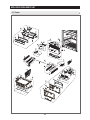
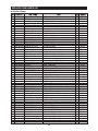
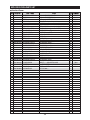
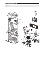
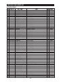
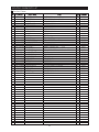
5. Exploded View & PARTS LIST ····································101
5-1) Freezer ···········································102
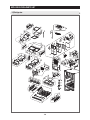
5-2) Refrigerator··········································106
5-3) Cabinet ···········································112
5-4) Disassembly of Freeze Door ··································116
5-5) Disassembly of Refrigerator DoorLeft ······························118
5-6) Disassembly of Refrigerator Door Right ·····························122
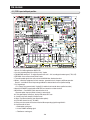
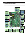
6. PCB DIAGRAM ··········································124
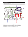
6-1) PCB Layout with part position ·································126
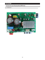
6-2) PCB Layout with part position (SMPS Board) ···························128
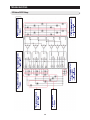
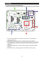
6-3) Connector Layout with part position (Main Board) ·························127
6-4) Connector Layout with part position (SMPS Board) ························128
7. WIRING DIAGRAM·········································129
7-1) Model : RFG298** ·······································129
8. SCHEMATIC DIAGRAM ·····································130
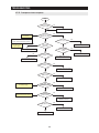
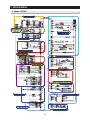
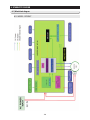
8-1) Whole block diagram ·····································130
8-1-1. MODEL : RFG298** ···································130
8-1-2. MODEL : RFG23*** ···································131
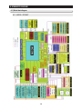
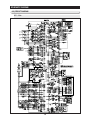
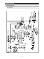
8-2) CIRCUIT DIAGRAM ······································132
8-2-1. Main ··········································132
8-2-2. INVERTER ·······································133
1. PRECAUTIONS(SAFETY WARNINGS)
● Unplug the appliance before the changing or repairing the electric parts.
→ Be careful the electric shock.
● When exchanging the parts, use the correct parts.
→ Check the model name, rating voltage, rating current, running
temperature symbols.
● When troubleshooting, connect firmly the types of harness.
→ Make not to be separated when some power is imposed.
● Check the traces of water infiltration at the electric parts.
→ If there is a trace of water infiltration, exchange or tape the parts.
● Check the assemble status of parts after troubleshooting.
→ It must be in the same assembled state when compared with the state before
disassembly.
● Check the use circumstance of refrigerator.
→ If the refrigerator is installed at the place that is damp or wet, or
status of installation is unstable, change the installation place.
● Ground the refrigerator properly
→ Particularly, Be sure to earth when there is a risk of an electric
leakage by humidity or wetness.
● Do not use multi plugs in a plug socket at the same time.
Check if the power cord and socket is damaged, pressed, squeezed,
or fired.
→ If the plug or plug socket is damaged, repair or exchange it
immediately.
● Do not allow consumers to repair the appliance by themselves.
● Do not store other materials except the foods.
→ Drugs or scientific materials : difficult to keep precise temperature.
→ The inflammables(alcohol, benzene, ether, LP gas, butane gas etc.):
have risk of explosion.
4
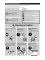
PRECAUTIONS(SAFETY WARNINGS)
Read all instructions before repairing the product and follow the instructions
in order to prevent danger or property damage.
Plug out and remove all the items in regrigerator prior to repair.
CAUTION/WARNING SYMBOLS DISPLAYED
Warning
SYMBOLS
means “Prohibited”.
Indicates that a
danger of death
or serious injury
exists.
means “Do not disassemble”.
means “No contact”.
means ”Warning or Caution”.
Caution
Indicates that a risk
of personal injury
or material damage
exists.
means “Unplug the unit before
preforming service”
means “Earth or Ground”.
Warning & Caution
Plug out to exchange the interior
lamp.
Use the rated components
on the replacement.
● It may cause electric shock.
●Check the correct model, rated
voltage, rated current, operating
temperature and so on.
On repair, make sure that the
wires such as harness are
bundled tightly.
●Bundle tightly wires in order not to be
detached by the external force and then not
to be wetted.
comRated
pone
nts
Unplug
On repair, remove completely dust
or other things of housing parts,
harness parts, and check parts.
●Cleaning may prevent the possible fire by
tracking or short.
After repair, check the
assembled state of components.
●It must be in the same assembled state
when compared with the state before
disassembly.
5
Check if there is any trace
indicating the permeation
of water.
●If there is that kind of trace, change
the related components or do the
necessary treatment
such as taping
using the
insulating tape.
PRECAUTIONS(SAFETY WARNINGS)
❈ Please let users know following warnings & cautions in detail.
Warning & Caution
Do not allow users to put bottles or
kinds of glass in the freezer.
Do not allow users to store narrow
and lengthy bottles or foods in a
small multi-purpose room.
Do not allow users to store
pharmaceutical products, scientific
materials, etc., in the refrigerator.
●Freezing of the contents may inflict a wound.
●It may hurt you when refrigerator door is
opened and closed resulting in falling stuff
down.
●The products which need precise
temperature control should not be stored in
the refrigerator.
Do not allow users to
disassemble, repair or alter.
Do not allow users to bend the
power cord with excessive force
or do not have the power cord
pressed by heavy article.
Do not allow users to plug
several appliances into the same
power receptable.
●May cause abnormal generation of
heat or fire.
Prohibition
Do not allow users to store
articles on the product.
●Opening or closing the door may cause
things to fall down, which may cause
injury.
●It may cause fire or abnormal
operation which leads to injury.
●May cause fire.
Do not
disassemble
Do not allow users to install the
refrigerator in the wet place or
the place where water splashes.
Make sure of the earth.
●Be sure the product is properly grounded.
●Deterioration of insulation of electric
parts may cause electric shock or fire.
Prohibition
Earth
6
PRECAUTIONS(SAFETY WARNINGS)
FLOORING
For proper installation, this refrigerator must be
placed on a level surface of hard material that is
the same height as the rest of the flooring. This
surface should be strong enough to support a fully
loaded refrigerator, or approximately
660lbs(299kg).
MOVING
Protect the finish of the flooring. Cut a large
section of the cardboard carton and place
under the refrigerator where you are working.
When moving, be sure to pull the unit straight
out and push back in straight.
7
2. PRODUCT SPECIFICATIONS
2-1) INTRODUCTION OF MAIN FUNCTION ···························9
2-2) SPECIFICATIONS ····································11
2-3) INTERIOR VIEWS ····································12
2-4) MODEL SPECIFICATION ·································13
2-5) MODEL SPECIFICATION &SPECIFICATION CHART ····················14
2-6)DIMENSIONS OF REFRIGERATOR (INCHES)························17
2-7) OPTIONAL MATERIAL SPECIFICATION ··························18
2-8) REFRIGERANT ROUTE IN REFRIGERATION CYCLE ····················19
2-9) COOLING AIR CIRCULATION ·······························25
8
2. PRODUCT SPECIFICATIONS
2-1) Introduction of Main Function
●
A newly developed SAMSUNG bottom mount freezer in 2008 has the following
characteristics.
Surround Multi Flow
● Uniform cooling for each shelf and even in corner in fresh
food compartment by centerpositioned fan and duct with
multiple flow effluences.
Twin Cooling System
● The refrigerator and the freezer have two evaporators.
Given this independent system, the freezer and the
refrigerator are cooled individually as required and are,
therefore, more efficient.
Food odor from the refrigerator does not affect food in the
freezer due to separate air flow circulation.
Electronic control from outside of Pantry Cover
● Adjustable temperature control ((around 41℉(5℃) : Deli /
around 38℉(3℃) : Fresh / around 34℉(1℃) Chilled )
Temperature control from outside of the Pantry : user
friendly design helps keep foods fresh for longer
16" Pizza Corner
● Can be used for 16" pizza if the flap is turned up
Ice and Water Dispenser
● The ice and water dispenser provides ice and cold water at
any time.
Secure Auto Close Door System
Secure Auto Close Door System
● Cool tight doors
● Energy saving
● Preventing sweat on fridge doors
●
Easy Handle System
● Ez-open Freezer Door
● Ergonomic Door Design
9
PRODUCT SPECIFICATIONS
Easy Handle
● The freezer door is more user-friendly.
So, it comes as much convenient.
Drawer
● The dimension of the right-side drawer is 6:4 (H x W)
with the shelf being raised.
So, the right-side drawer can be pulled out with the
left door closed.
Dual Ice Maker
● 9 cubes ice-Maker(Refrigerator)
● 7 cubes ice-Maker(Freezer)
10
PRODUCT SPECIFICATIONS
2-2) Specifications
ELECTRICAL SPECIFICATIONS
Defrost Control
From 24 to 32 hrs
Thermo Bimetal Protector 140°F(60℃)(off) 104°F(40℃)(on)
Defrost Thermistor(502AT)
50°F(10℃)(off)
Electrical Rating
AC115V 60Hz 11.6 Amps
Maximum Current Leakage
0.25 mA
Maximum Ground Path Resistance
0.1 Ohm
Energy Consumption
550KWh/year
Refrigerator
Fan
(Air inlet)
(Air inlet)
Fan
Heat exchanger
Fan
NO LOAD PERFORMANCE
(Air inlet)
(Air inlet)
Fan
90℉(32℃)
Ambient Temperature
70℉(21℃)
Refrigerator,℉
34℉(1℃)∼46℉(8℃) 34℉(1℃)∼46℉(8℃)
Freezer,℉
-8℉(-22℃)∼8℉(-13℃) -8℉(-22℃)∼8℉(-13℃)
Run Time,%
40
60
Heat exchanger
Fan
REFRIGERATION SYSTEM
Freezer
Refrigerant Charge (R134a)
5.64 oz(160g)
Compressor(BK190C-L2C)
1314 Btu/hr(0.385kw)
Compressor oil
Freol α15c
",118"
"(0.82mm,3500mm)
R Capilary tube(Dia, Length)
0.032"
",118"
"(0.82mm,3500mm)
F Capilary tube(Dia, Length)
0.032"
Dryer
C-Fan
Fan
(Air inlet)
Heat exchanger
Noise Filter
(Air inlet)
Compressor
condenser
Water Valve
INSTALLATION
Clearance must be provided for air circulation
AT TOP
AT SIDES
AT REAR
" (25mm)
1"
" (25mm)
1"
" (50mm)
2"
11
PRODUCT SPECIFICATIONS
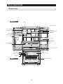
2-3) Interior Views
Refrigerator
Light
Auto Door Closer
FF Ice-Maker
Foldable-Shelf
Water Filter
Dairy Compartment
Slide-Shelf
Slide-Shelf
Vertical Hinged
Section
Door Bins
Quick-Space
Glass Shelf
Vegetable & Fruit
Drawers
Cool Select Pantry
Light
Pull Out Drawer
FZ Ice-Maker
Tilting Pocket
Ice Bucket
Freezer
Freezer Drawer Bin
12
TM
PRODUCT SPECIFICATIONS
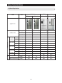
2-4) Model Specification
SAMSUNG
ITEM
MAYTAG
LG
SPEC
RFG298AA
RFG297AA
MFI2568AES
LFX25960ST
Cooling Tech
Twin Cooling
Twin Cooling
Mono Cooling
Mono Cooling
Door Shape
Contour
Contour
Contour
Contour
Pantry
Pantry
Appearance
Product Zone
Performance
Special Room Cool Select Pantry Cool Select Pantry
Cooling
F-Room
250↓
231.2
199.2
246
224
Speed(Min)
R-Room
250↓
209.3
197.3
575
232
F-Room
-26.0↓
-27.8
-28.1
-27.2
-28.8
R-Room
2.0↓
1.7
0.7
1.6
-1.8
F-Room
-18.0↓
-22
-21.5
-20.9
-22.5
R-Room
5.0↓
2
1.3
5.9
0.8
Temperature F-Room
Distribution
(Fridge) R-Room
2.0↓
0.2
0.2
0.6
1.3
2.0↓
0.4
0.3
1.1
0.5
N-N
80%↓
68.4
62.5
60.7
56.5
Sound power level
46dB↓
45
41
47
41.7
Sound Pressure level
45dB↓
43.8
38.6
48.2
40.1
89.6℉(32°C)
89.6℉(32°C)
Noise
Running Rate
13
PRODUCT SPECIFICATIONS
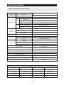
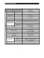
2-5) Model Specification &Specification Chart
ITEM
RFG298AA
Model
W
35 3/4 inch (908mm)
On Cabinet
29 1/8 inch (740mm)
W/O Handle
32 7/8 inch (836mm)
With Handle
35 3/4 inch (905mm)
W/O Hinge Cap
68 3/4 inch (1743mm)
With Hinge Cap
69 ¾ Inch (1773mm)
D
External size
H
Net
Capacity
Ice & Water Dispenser with Pantry
Total
28.5 Cu.ft (807.1ℓ)
Freezer
9.0 Cu.ft(254.9ℓ)
Refrigerator
19.5 Cu.ft(552.2ℓ)
55.4%
Efficiency of Volume
Weight
Set
328.5 Pounds (149kg)
Packing
359.3 Pounds (163kg)
Width
38 5/8 Inch (980mm)
Depth
39 3/8 Inch (1001mm)
Height
75 5/8 Inch (1923mm)
Packing
Compressor
Reciprocate
Rated Frequency and Frequency
AC 115V/60Hz
Refrigerant
R 134a
Foaming Agent
C-Pentane
Refrigerant Input Amount
5.64 oz (160g)
Type Refrigerator
Indirect Cooling Method Refrigerator
Motor Rated Consumption Power
165W
Electric Heater Rated Consumption Power
380W
COLOR
Cabinet (Both Side)
Door
Molding
Black
All Black
Empire Black
I Black
Real STS
Noble STS
Versailles Stainless
Creamy STS
White
Snow White
Snow White
Snow White
Platinum STS
Noble STS
Stainless Platinum
Creamy STS
14
PRODUCT SPECIFICATIONS
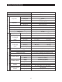
Specification
Model
RFG298AA
Compressor
Components for Freezer
Defrost Sensor Defrost Cycle
Refrigerator
Freezer
Evaporator
Bimetal
Room Temperature Sensor Components
Defrost Related Components
Items
Model
BK190C-L2C
Starting type
BLDC
Oil Charge
FREOL α- 15c
Freezer
SPLIT FIN TYPE
Refrigerator
SPLIT FIN TYPE
Condenser
Forced and Natural Convection Type
Dryer
Molecular shieve XH-9
Capillary tube(Dia x Length)
R : 0.032” x 118” (0.82mm x 3500mm) / F : 0.032” x 118” (0.82mm x 3500mm)
Refrigerant
R134a
Model
Temperature Selection
ON(℉)
OFF(℉)
THERMISTOR
-14℉(-26℃)
-11℉(-24℃)
-17℉(-27℃)
(F-SENSOR)
-2℉(-19℃)
1℉(-17℃)
-5℉(-21℃)
502AT
8℉(-13℃)
11℉(-12℃)
5℉(-15℃)
Model
Temperature Selection
ON(℉)
OFF(℉)
THERMISTOR
34℉(1℃)
36℉(2℃)
32℉(0℃)
(R-SENSOR)
38℉(3℃)
40℉(4℃)
36℉(2℃)
502AT
46℉(8℃)
48℉(9℃)
44℉(7℃)
First Defrost Cycle (Concurrent defrost of F and R)
6hr ±10min
Defrost Cycle(FRE)
12~22hr(vary according to the conditions used)
Defrost Cycle(REF)
6~11hr(vary according to the conditions used)
Pause time
12 ±1min
F Defrost-Sensor
R Defrost-Sensor
F Bimetal-thermo
Protector
R Bimetal-thermo
Protector
Model
THERMISTOR (502AT)
SPEC
5.0 ㏀ at 77℉(25℃)
Model
THERMISTOR (502AT)
SPEC
5.0 ㏀ at 77℉(25℃)
Rated
AC 125V 10A
Operating temperature
Off : 140℉(60℃) / On : 104℉(40℃)
Rated
AC 125V 10A
Operating temperature
Off : 140℉(60℃) / On : 104℉(40℃)
15
PRODUCT SPECIFICATIONS
Items
Specification
Model
RFG298AA
Defrost Heater(FRE)
Heated at F Defrost
AC 115V, 240W
Defrost Heater(REF)
Heated at R Defrost
AC115V, 120W
DISPENSER Heater
Interlock with French Heater
AC115V, 1.6W
FRENCH Heater
-
AC115V, 8W
ICE Duct Heater
Interlock with Defrost Heater (FRE)
AC115V, 4W
Water Tank Heater
-
DC 12V, 2W
Water Pipe Heater
-
DC 12V, 2W
Electric Components
Bimetal thermo for Preventing Overheating of Refrigerator Lamp
Over Load Relay
AC125V 6A / AC250V 3A Off: 140℉(60℃)/ On : 104℉(40℃)
Model
4TM445PHBYY-82
Temp.ON
156.2± 16.2℉(69± 9℃)
Temp.OFF
257± 9℉(125± 5℃)
Rated Voltage
AC 115V/ 60Hz
Motor-BLDC(FRE)
DC12V / DREP5020LC
Motor BLDC(ICE ROOM)
DC12V / DREP5020LB
Motor-BLDC(REF)
DC12V / DREP5020LC
Motor-BLDC(CIRCUIT)
DC12V / DRCP5030LA
Motor-DAMPER(PANTRY)
DC12V / NSBY001TD1
Lamp(FRE)
AC 120V / 60W(1EA)
Lamp LED (REF)
DC 12V / 720mA
Lamp LED (VEG)
DC 12V / 60mA
FRE
AC 125V 1.5A (1EA)
REF
DC200V 1.5A / MS-406-SS-01(2EA)
REF(ICE ROOM)
125V/5A, EMB816
Door Switch
Power Cord
AC125V 15A
Earth Screw
BSBN (BRASS SCREW)
16
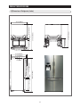
2 1/2"(64.5mm) 24
42 1/2"(1080.5mm)
69 3/4"(1773mm)
9/16"(15mm)
1/4"(618mm)
35 5/8"(905mm)
32 7/8"(836mm)
3/16"(5mm)
1.3"(34mm)
17
47 3/4"(1214mm)
18 3/4"(475mm)
54 1/2"(1384mm)
21 5/8"(549mm)3 3/8"(87mm) 29 1/8"(740mm)
PRODUCT SPECIFICATIONS
2-6)Dimensions of Refrigerator (Inches)
35 3/4"(908mm)
PRODUCT SPECIFICATIONS
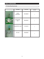
2-7) Optional Material Specification
Part Name
Part Code
FILTER
WATER-ASSY
DA29-00003B
ASSY-PACKING
SUB
DA99-00240S
INCANDESCENT LAMP
4713-001223
LED LAMP
DA96-00329A
18
AMOUNT
1
1
1
1
PRODUCT SPECIFICATIONS
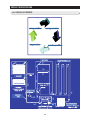
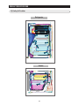
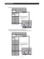
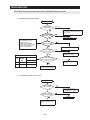
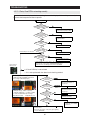
2-8) Refrigerant Route in Refrigeration cycle
1. Compressor → Sub-condenser → Hot Pipe → Back Cluster Pipe → Dryer → R Capillary Tube → Refrigerator
Evaporator → Freezer Evaporator → Suction Pipe → Compressor
2. Compressor → Sub-condenser → Hot Pipe → Back Cluster Pipe → Dryer → F Capillary Tube → Freezer
Evaporator → Suction Pipe → Compressor
19
PRODUCT SPECIFICATIONS
2-8-1. PRINCIPLE OF FREEZEER
4.17m
20
PRODUCT SPECIFICATIONS
2-8-2. Operation theory of refrigeration cycle components
■ Condenser
1) Role: A device which radiates heat to the outside (water/air) to make liquid state for the high
temperature / high pressure gas refrigerant discharged from compressor
2) Types
A. Air-cooling Type : Condense air by circulating naturally or manually.
1) Natural Convection Type : Used for the household refrigerator which has small condensing
capacity.
2) Manual Convection Type : Circulate air manually by FAN-Motor (Large capacity)
B. Water-cooling Type : Make cooling water pass through the pipe in the condenser (Large
capacity)
※ Location
① CLUSTER heat-radiating type : All Pipes effective for radiating heat are formed in the
right/left, and front side of refrigerator with hard urethanes and radiate heat through
the whole surfaces of cabinet to ambient air.
② Install the condenser on the outside of the product. (An old model)
③ Make them cluster at the lower part of product and radiate heat manually by fan.
☞ Radiate condensed potential heat up to liquefy completely and make change the state
without changing the gas temperature itself.
※ Pipe thickness
① Low pressure: 6.3mm ② High pressure : 4.7mm ③ Capillary : About 0.4-0.8mm
※ Condenser length (Based on 300ℓ): 26.5 M
① Assistance : 5 M ② HOT-PIPE: 6.6 M ③ CLUSTER-PIPE: 4.17 M
■ Capillary
1. Role: A device which makes low temperature and pressure refrigerant by reducing the
pressure the normal temperature / high pressure liquid refrigerant condensed from
condenser, and supply it to the evaporator.
A. To evaporate more lower temperature in case of evaporation.
B. It flows to the evaporator without back flowing to condenser, if compressor stops, and the
difference of pressure between high pressure and low pressure is small so it is easy to
operate the compressor again.
2. Outline
A. Thickness : About 0.4-0.8ßÆ
B. Length : It is changeable to low temperature and pressure (10->5ß∏/ß≤) depends on the
2M of thin and long copper pipe wall resistance.
21
PRODUCT SPECIFICATIONS
2-8-3. Operation theory of refrigeration cycle components
■ Evaporator
1. Role: As the low pressure liquid refrigerant flowed from capillary absorbs heat inside of the
refrigerator, it becomes low pressure gas and refrigerate the foods.
2. Theory: The low pressure refrigerant flowed to evaporator operates cooling which takes
ambient evaporated potential heat with maintaining the evaporation up to evaporate
completely.
3.Types of Evaporator
A. ROLL-BOND Evaporator → Direct Cooling ONE-DOOR Type
☞ Rolled and adhere the 2 aluminum plate and then make refrigerant passage.
B. PIN-PIPE Type → Indirect cooling TWO-DOOR Type
☞ a small aluminum plate on the aluminum pipe to increase the cooling effect.
■ Compressor
1. Role: It operates same as pump which pull out the subterranean water. It inhales the low
temperature and pressure refrigerant gas (flowed out) from evaporator and make high
temperature and pressure refrigerant liquid in the compressor and send it to the condenser.
2. Type of Condenser
a. Back-and-forth motion type: A method that pistol makes back-and-forth motion through
shaft and cylinder of motor rotation and compresses. ※ Used for household refrigerant
b. Rotary Type: A method that inhales the refrigerant gas through the gap between the
outside of rotor electric attached on the shaft and the inside of cylinder and compresses.
c. Centrifugal Type
3. Please insert the explanation of inverter comp operation theory.
■ Dryer
1. Role: Absorb the moisture from the refrigerant that refrigeration cycle circulates and
eliminate the foreign substance.
2. Structure: If even some moisture is included refrigerant is impossible to circulate by freezing
the small capillary outlet, so silica gel or molecular sieve is (included and) sealed to absorb
the internal moisture, and install a minute net to eliminate the foreign substance.
22
PRODUCT SPECIFICATIONS
2-8-4. Operation theory of refrigeration cycle components
※.Influence of moisture
① Moisture precipitation – Blocked by ice
② Refrigerant and reaction
③ Life reduction of oil
④ Acceleration of oxidization
⑤ Copper plating phenomenon
⑥ Gas dissolution by the interaction of synthetic insulating material (insulator)
※.Influence of foreign substance
① Increase of condensed temperature.
② Increase of temperature.
③ Decrease of cooling efficiency
④ Shorten the life by friction between oil and foreign substance in the compressor.
■ Accumulator
1. Role : To send a pure refrigerant gas to compressor by removing completely the refrigerant
liquid from evaporator.
※ If a refrigerant liquid go into the compressor, overload is occurred.
23
PRODUCT SPECIFICATIONS
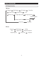
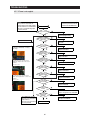
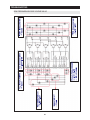
2-8-5. Refrigeration Cycle Type
TDM Cycle
Compressor
Sub-Condenser
Freezer Hot-Pipe
3Way Valve
Fin-Condenser
Fridge Hot-Pipe
Cluster Rear
Dryer
Fridge Capillary Tube
Fridge Evaporator
Connected Capillary
Freezer Evaporator
Freezer Capillary Tube
Suction Pipe
Accumulator
HM Cycle
Compressor
Sub-Condenser
Dryer
Capillary Tube
Freezer Evaporator
Hot Pipe
Refrigerator Evaporator
Suction Pipe
24
Compressor
PRODUCT SPECIFICATIONS
2-9) Cooling Air Circulation
Refrigerator
Freezer
25
3. DISASSEMBLY AND REASSEMBLY
3-1) PRECAUTION ······························27
3-2) REFRIGERATOR DOOR ·························28
3-3) DOOR HANDLE FREEZER ························30
3-4) REFRIGERATOR LIGHT ·························31
3-5) COVER-DISPLAY & WATER-DISPENSER··················31
3-6) WATER-DISPENSER ···························32
3-7) GLASS SHELF ·····························33
3-8) FOLDABLE GLASS SHELF ························34
3-9) VEGETABLE & FRUIT DRAWERS SHELF ·················34
3-10) COOL SELECT PANTRY·························35
3-11) WATER TANK ·····························36
3-12) MOTOR DAMPER····························38
3-13) WATER FILTER (DISASSEMBLY) ·····················38
3-14) WATER FILTER (REASSEMBLY) ·····················39
3-15) GALLON DOOR BIN ··························39
3-16) VERTICAL HINGED SECTION ······················40
3-17) EVAPORATOR COVER IN REFRIGERATOR ················41
3-18) EVAPORATOR IN REFRIGERATOR ····················42
3-19) FREEZER DOOR ····························43
3-20) PULL OUT DRAWER ··························44
3-21) ICE-MAKER ······························45
3-22) FREEZER LIGHT ····························46
3-23) DOOR SWITCH IN FREEZER ······················46
3-24) EVAPORATOR COVER IN FREEZER ···················47
3-25) EVAPORATOR IN FREEZER ·······················47
3-26) MACHINE COMPARTMENT ·······················48
3-27) ELECTRIC BOX ····························51
26
DISASSEMBLY AND REASSEMBLY
3-1) PRECAUTION
• Unplug the refrigerator before cleaning and making repairs.
• Do not dissemble or repair the refrigerator by yourself.
- It may cause risk of causing a fire, malfunction and/or personal injury.
• Remove any foreign matter or dust from the power plug pins.
- Otherwise there is a risk of fire.
• Do not use a cord that shows cracks or abrasion damage along its length or at either end.
• Do not plug several appliances into the same multiple power board. The refrigerator should always be plugged
into its own individual electrical which has a voltage rating that matched the rating plate.
- This provides the best performance and also prevents overloading house wiring circuits, which could cause a fire
hazard from overheated wires.
• Do not install the refrigerator in a damp place or place where it may come in contact with water.
- Deteriorated insulation of electrical parts may cause an electric shock or fire.
• The refrigerator must be grounded.
- You must ground the refrigerator to prevent any power leakages or electric shocks caused by current leakage
from the refrigerator.
• Do not put bottles or glass containers in the freezer.
- When the contents freeze, the glass may break and cause personal injury.
• Do not store volatile or flammable substances in the refrigerator.
- The storage of benzene, thinner, alcohol, ether, LP gas and other such products may cause explosions.
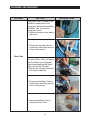
- Required Tools
IMAGE
ITEM
USE
Phillips Head Driver
Use for assembling and
disassembling of screw
Flat Head Driver
Use for assembling and disassembling
of HomeBar, Dispenser, Deli
Cartessen Box, Main PBA etc...
Hex Wrench Ø2mm
Use for assembling and
disassembling of Handle
Socket Wrench Ø10mm
Use for assembling and
disassembling of Door Hinge
- Water whitening phenomenon
All water provided to refrigerators flows through the core filter which is an alkaline water filter. In this process, the
pressure in the water that has flowed out of the filter gets increased, and massive oxygen and nitrogen become
saturated. When this water flows out in the air, the pressure plummets and the oxygen and nitrogen get
supersaturated so that they turn into gas bubbles. The water could look misty due to these oxygen bubbles. It is not
because dust or chemicals, just a few seconds later, it will be clean again.
27
DISASSEMBLY AND REASSEMBLY
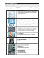
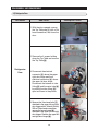
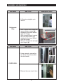
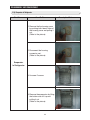
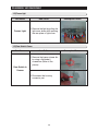
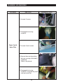
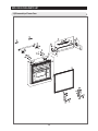
3-2) Refrigerator Door
Part Name
How To Do
Descriptive Picture
1. With the door opened, remove
the Top Table cap(1⃞) with a Flat
head screwdriver, and close the
door.
1⃞
2⃞
2. Remove the 3 screws holding
down the Top Table and remove
the Top Table(2⃞).
Refrigerator
Door
3⃞
3. Disconnect the electrical
connector(3⃞) above the upper
right door hinge and the 3
electrical connectors(4⃞) above
the upper left door hinge.
Disconnect the fastener in tube
fitting(5⃞) and the water tube(6⃞)
by pulling the tube fitting (5⃞)
apart as shown in the picture.
4⃞
5⃞
4. Remove the 3 hex head bolts(7⃞)
attatched to the upper left and right
door hinges with a Wrench(10mm).
With a Philips head screwdriver,
remove the ground screw(8⃞)
attatched to the upper left and right
door hinges. Remove the upper left
and right door hinges(9⃞).
28
6⃞
8⃞
9⃞
7⃞
DISASSEMBLY AND REASSEMBLY
Part Name
How To Do
Descriptive Picture
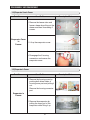
5. Lift the door straightly up to
remove.
Refrigerator
Door
Part Name
6. With a Philips head screwdriver,
remove the two screws ([10])
attatched to the lower left and
right door hinges.
With a wrench(10mm), remove
the 2 flat head screws ([11])
attatched to the lower left and
right door hinges.
Remove the lower left and right
door hinges ([12]).
How To Do
1. Using a wrench, unscrew the
two screws. And disassemble
the door handle.
COVER VINYL
2. Remove the cover vinyl of door.
29
[12]
[10]
[11]
Descriptive Picture
DISASSEMBLY AND REASSEMBLY
3-3) Door Handle Freezer
Part Name
How To Do
Descriptive Picture
1. Remove the Cap Door with a
flat-blade(-) screwdriver.
2.Remove 4 screws
Door Handle
Freezer
1⃞
3. Lift up the handle to have the
Slider Handle Fre(1⃞) pushed
back.
4. After having the Slider Handle
Fre(1⃞) pushed back, screw up
at the hole.
5.Remove the door handle by
lifting it up.
30
1⃞
DISASSEMBLY AND REASSEMBLY
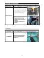
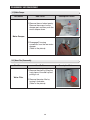
3-4) Refrigerator Light
Part Name
How To Do
Descriptive Picture
1. Remove the lamp cover by
pulling it down as pushing the
rear of lamp cover.
Refrigerator
Light
2. Remove the screw. And
separate the LED panel.
3-5) Cover-Display & Water-Dispenser
Part Name
How To Do
Descriptive Picture
1. Remove the display cover by
pushing it to the right side and
pulling it up.
②
①
Cover-Display
2. Disengage the housing connect
of display cover.
3. Remove 4 screws of coverdisplay.
31
DISASSEMBLY AND REASSEMBLY
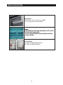
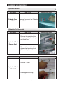
3-6) Water-Dispenser
Part Name
How To Do
1. Disengage the 3 Housing
Connectors.
2. Remove 2 screws of the Case
Ice Route Assy.
Water-Dispenser
3. Pull the Case Ice Route Assy.
4. Push the hook and remove the
Micro Switch.
32
Descriptive Picture
DISASSEMBLY AND REASSEMBLY
Part Name
How To Do
Descriptive Picture
Hose
1. Assembly shall be in order from
the disassembly. Case-Ice and
Route shall be assembled inside
of hose. Otherwise, assemble
cannot be accomplished.
Water-Dispenser
2. When assembling CoverDisplay, first insert it from
leftside and then assemble to
rightside.
Otherwise, the hook can be
broken.
3-7) Glass Shelf
Part Name
Glass Shelf
How To Do
Remove the shelf by lifting the
front part of the shelf up and
pulling it out.
33
Descriptive Picture
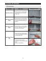
DISASSEMBLY AND REASSEMBLY
3-8) Foldable Glass Shelf
Part Name
Foldable Glass
Shelf
How To Do
Descriptive Picture
Remove 2 screws of the Folderble
Glass Shelf
3-9) Vegetable & Fruit Drawers Shelf
Part Name
How To Do
Descriptive Picture
1. Remove the vegetable & fruit
drawer by pulling the roller part
and lifting it up.
Vegetable & Fruit
Drawers Shelf
2. Remove the vegetable & fruit
drawer shelf by pulling it out.
(Refer to the picture)
Part Name
How To Do
1. Remove 1 screw
Vegetable & Fruit
LED LAMP
2. Disengage the housing
connector.
34
Descriptive Picture
DISASSEMBLY AND REASSEMBLY
3-10) Cool Select Pantry
Part Name
How To Do
1. Remove the cool select pantry
by pulling the roller part and
Cool Select Pantry
lifting it up.
Cool Select Pantry
Cover
1. Remove the cool select pantry
cover by lifting the central part
of the cover while pushing it to
the left.
Cool Select Pantry 1. Remove the cool select pantry
shelf by lifting the front part of
Shelf
the shelf while pulling it.
1. Remove the cool select pantry
rail by unscrewing the 3 screws
and pulling the rail.
Cool Select Pantry
Rail
2. Disconnect the housing
connector from the internal rail
part.
(Refer to the picture)
35
Descriptive Picture
DISASSEMBLY AND REASSEMBLY
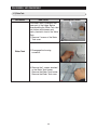
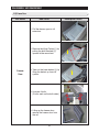
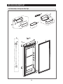
3-11) Water Tank
Part Name
How To Do
The Water Tank is located in the
lower part of the fridge. Before
disassembling the Water Tank take
out shelves and drawers and
pantry located in front of the Water
Tank.
1. Remove 2 screws of the Water
Tank cover.
Water Tank
2. Disengage the housing
connector.
3. Remove the 1 screws attached
to the Water Tank Heater.
Remove the Water Tank heater.
Remove the Water Tank cover.
36
Descriptive Picture
DISASSEMBLY AND REASSEMBLY
Part Name
How To Do
One Water Tube is located in the
machine compartment of the
refrigerator. Before disassembling
the Water Tube, take out the
compressor cover.
5. Remove the water valve fixed by
the screw.
6. Disconnect the water tube by
pushing the tube fitting apart as
shown in the picture.
Water Tank
The other Water Tube is located in
the Top Table of the refrigerator.
Before disassembling the Water
Tube, take out the Top table.
7.Remove the cap tube fitting with
a flat head screwdriver.
8. Disconnect the Water Tube by
pushing the tube fitting apart as
shown in the picture.
9. Remove the Water Tank by
pulling the Water Tube.
37
Descriptive Picture
DISASSEMBLY AND REASSEMBLY
3-12) Motor Damper
Part Name
How To Do
Descriptive Picture
1. Remove the cool select pantry.
Remove the screw of motor
damper part and than push the
motor damper down.
Motor Damper
2. Disengage 2 housing
connectors from the rear motor
damper.
(Refer to the picture)
3-13) Water Filter (Disassembly)
Part Name
How To Do
1. Remove the shelf by lifting the
front plane of the shelf up and
pulling it out.
Water Filter
2. Remove the water filter by
turning it clockwise.
(Refer to the picture)
38
Descriptive Picture
DISASSEMBLY AND REASSEMBLY
3-14) Water Filter (Reassembly)
Part Name
How To Do
Descriptive Picture
1. Place the part of (ⓐ) arrow (that
is indicating in the picture) in the
middle of the front filter cover
and push it up.
Water
Filter
ⓐ
2. Turn the water filter
counterclockwise until central
horizontal line of filter cover and
both ends of water filter label
are aligned.
(Refer to the picture.)
3-15) Gallon Door Bin
Part Name
How To Do
Gallon Door Bin
1. Remove the gallon door bin by
lifting it up.
(Refer to the picture)
39
Descriptive Picture
DISASSEMBLY AND REASSEMBLY
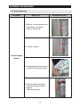
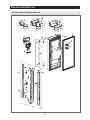
3-16) Vertical Hinged Section
Part Name
How To Do
1. Remove 2 screw cap parts with
a flat-blade(-) screwdriver.
(Refer to the picture)
2. Unscrew 2 screws.
Vertical Hinged
Section
3. Disengage the internal housing
connector of the vertical hinge.
4. Remove the vertical hinged
section by lifting the vertical
hinge up.
(Refer to the picture)
40
Descriptive Picture
DISASSEMBLY AND REASSEMBLY
3-17) Evaporator Cover In Refrigerator
Part Name
How To Do
Descriptive Picture
1. Remove the angle cap with a
flat-blade screwdriver.
(Refer to the picture)
2. Unscrew 4 screws.
Evaporator Cover
In Refrigerator
3. Remove the the lower part of
angle mid by pulling it out and
pushing it down.
(Refer to the picture)
4. Remove the hook by pulling it
from the lower part and pushing
the cover down.
(Refer to the picture)
5. Disconnect the housing
connector of the rear plane.
(Refer to the picture)
41
DISASSEMBLY AND REASSEMBLY
3-18) Evaporator In Refrigerator
Part Name
How To Do
1. Remove the the housing cover
by pushing both lateral sides of
the housing cover and pulling it
out.
(Refer to the picture)
2. Disconnect the housing
connector part.
(Refer to the picture)
Evaporator
In Refrigerator
3. Unscrew 2 screws.
4. Remove the evaporator by lifting
the bottom side of it up and
pulling it out.
(Refer to the picture)
42
Descriptive Picture
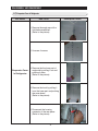
DISASSEMBLY AND REASSEMBLY
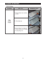
3-19) Freezer Door
Part Name
How To Do
Descriptive Picture
1. Pull the drawer open to full
extension.
2. Remove the tilting Pocket(①) by
pulling the both brackets(②)
upward at the same time.
Freezer
Door
3. Take out the lower basket(③) by
lifting the basket up from rail
system.
4. Unscrew 4 bolts.
(2 bolts each on the both sides)
5. Lifting up the freezer door,
remove the freezer door from
the rail.
43
②
①
③
DISASSEMBLY AND REASSEMBLY
3-20) Pull Out Drawer
Part Name
How To Do
1. Slide the drawer in as much as
possible.
Door
Handle
Freezer
2. Lift the drawer up.
3. Remove the pull out drawer by
lifting the bottom part of drawer
bin and pulling it out.
44
Descriptive Picture
DISASSEMBLY AND REASSEMBLY
3-21) Ice-Maker
Part Name
How To Do
Descriptive Picture
lever
1. Pull the lever forward and take
out the ice bucket.
2. Remove 1 screw of the Cover.
Ice Maker
3. Disassemble the cover with a
flat-blade(-) screwdriver and pull
it out.
4. Disengage the 2 housing
connectors.
5. Push the hook and pull the IceMaker out.
6. To disassemble, push the tab
and pull the Case-Auger and the
motor out.
45
DISASSEMBLY AND REASSEMBLY
3-22) Freezer Light
Part Name
How To Do
Freezer Light
1. Remove the light by pulling the
light cover down while pushing
the rear plane of light cover.
Descriptive Picture
3-23) Door Switch In Freezer
Part Name
How To Do
1. Remove the freezer drawer bin
by using a flat-blade(-)
screwdriver.(Refer to the
picture)
Door Switch In
Freezer
2. Disconnect the housing
connector part.
46
Descriptive Picture
DISASSEMBLY AND REASSEMBLY
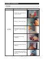
3-24) Evaporator Cover In Freezer
Part Name
How To Do
Descriptive Picture
1. Remove the freezer door and
freezer drawer by pulling out the
drawer and then unscrewing 2
screws.
Evaporator Cover
In
Freezer
2. Lift up the evaporator cover.
3. Disengage the 3 housing
connectors and remove the
evaporator cover.
3-25) Evaporator In Freezer
Part Name
How To Do
1. Remove the housing cover by
pushing both lateral sides of
housing cover part and pulling it
out.
Remove the housing connector
part.
Evaporator In
Freezer
2. Remove the evaporator by
pulling the lower part of the
evaporator while lifting it up.
47
Descriptive Picture
DISASSEMBLY AND REASSEMBLY
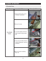
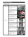
3-26) Machine Compartment
Part Name
How To Do
1. Unscrew 5 screws of cover
compressor.
2. Disengage the housing
connector.
(Refer to the picture)
3. Remove the hooker of support
circuit motor by lifting the hooker
up and pulling it out.
Motor Fan
4. Remove the screw with a flatblade screwdriver.
(Refer to the picture)
5. Remove the motor fan by pulling
the fan out while graping the
motor part.
(Refer to the picture)
6. Unscrew 2 screws fixed in the
motor.
7. Remove the hook of the motor
cover with a flat-blade (-)
screwdriver and then remove
the motor.
48
Descriptive Picture
DISASSEMBLY AND REASSEMBLY
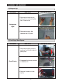
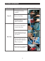
Part Name
How To Do
1. Disengage the housing
connector.
Relay O/L
2.Remove Cover Relay.
3. Remove the relay O/L with a
flat-blade screwdriver.
(Refer to the picture)
1. Unscrew the screw which is
fixing the Water Valve.
2. Disassembling the fixer hose
which is fixing the four hoses
like a picture.
Water Valve
3. Remove 2 water hose parts
while pushing the upper part of
①.
(Refer to the picture)
4. Remove the hose connected by
the nut with a wrench(8mm).
49
Descriptive Picture
DISASSEMBLY AND REASSEMBLY
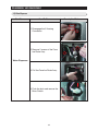
Part Name
How To Do
1. Unscrew 2 screws.
2. Disengage the housing
connector.
Power Cord &
Noise Filter
3. Unscrew 2 earth screws.
4. Remove the cover by pushing
the hook up using a flat-blade(-)
screwdriver.
(Refer to the picture)
5. Disengage the housing
connector to separate the power
cord and noise filter.
50
Descriptive Picture
DISASSEMBLY AND REASSEMBLY
3-27) Electric Box
Part Name
How To Do
1. Pull the refrigerator forward to
have enough space to work at
the rear side of the appliance.
2. Unscrew 2 screws of the PCB
cover.
PBA Main
3. Disengage all housing
connectors from the main PCB.
4. Remove the main PCB by lifting
the upper part of the hook up.
(Refer to the picture)
PBA SMPS
1. Remove the cover PCB and
then disengage the housing
connector connected with main
PCB.
Remove the SMPS PCB by
pushing the lower part of the
hook down.
51
Descriptive Picture
4. TROUBLESHOOTING
4-1) FUNCTION FOR FAILURE DIAGNOSIS ···························53
4-1-1. TEST MODE (MANUAL OPERATION / MANUAL DEFROST FUNCTION) ···········53
4-1-2. DISPLAY FUNCTION OF COMMUNICATION ERROR ···················54
4-1-3. SELF-DIAGNOSTIC FUNCTION ····························55
4-1-4. DISPLAY FUNCTION OF LOAD CONDITION ·······················58
4-1-5. EXHIBITION MODE SETTING FUNCTION ························59
4-1-6. OPTION SETTING FUNCTION·····························60
4-1-7. OPTION TABLE ···································62
4-2) DIAGNOSTIC METHOD ACCORDING TO THE TROUBLE SYMPTOM(FLOW CHART) ·······64
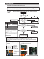
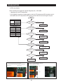
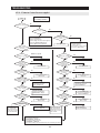
4-2-1. IF THE TROUBLE IS DETECTED BY SELF-DIAGNOSIS ··················65
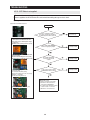
4-2-2. IF FAN DOES NOT OPERATE(F, R, C - FAN) ·······················76
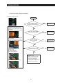
4-2-3. IF ICE ROOM FAN DOES NOT OPERATE ························77
4-2-4. IF ICE MAKER DOES NOT OPERATE··························78
4-2-5. IF DEFROST DOES NOT OPERATE ··························79
4-2-6. IF DEFROST DOES NOT OPERATE (F,R DEF HEATER) ··················80
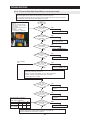
4-2-7. IF POWER IS NOT SUPPLIED ·····························81
4-2-8. IF COMPRESSOR DOES NOT OPERATE ························82
4-2-9. WHEN ALARM SOUNDS CONTINUOUSLY WITHOUT STOP(RELATED WITH BUZZER SOUND) ···84
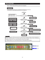
4-2-10. IF PANTRY PANEL PCB IS NOT WORKING NORMALLY ·················86
4-2-11. IF PANTRY PANEL PCB IS NOT WORKING NORMALLY ·················87
4-2-12. WHEN REFRIGERATOR ROOM LAMP DOES NOT LIGHT UP···············88
4-2-13. IF ICE WATER IS NOT SUPPLIED ···························90
4-2-14. IF CUBED OR CRUSHED ICE IS NOT SUPPLIED ····················92
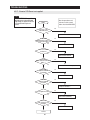
4-2-15. IF COVER ICE ROUTE MOTOR(GEARD MOTOR) IS NOT WORKING NORMALLY ······93
4-2-16. IF PHOTOSYNTHETIC LED LAMP DOES NOT WORK PROPERLY ·············94
4-2-17. IF INVERTER PCB POWER IS NOT SUPPLIED ·····················95
4-2-18. IF COMPRESSOR DOES NOT OPERATE ·······················96
4-2-19. LED BLINKING FREQUENCY DEPENDING ON PROTECTING FUNCTIONS ········97
SPM INTERNAL DIODE VOLTAGE ·······························98
INVERTER CONTROLLER BOARD CONNECTOR LOCATION ···················99
INVERTER PCB CIRCUIT DIAGRAM ·····························100
52
TROUBLESHOOTING
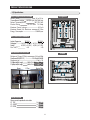
4-1) Function for failure diagnosis
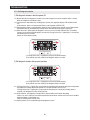
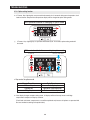
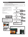
4-1-1. Test mode (manual operation / manual defrost function)
● If Energy Saver Key + Fridge Key on the front of panel are pressed simultaneously for 8 seconds , it will
be changed to the test mode and all displays on the front of panel will be off.
● If any key on the front of panel is pressed within 15 seconds after the test mode, it will be operated as
below sequence :
manual operation(Freezer compartment 1) → manual operation(Freezer compartment 2) → manual
operation(Freezer compartment 3) → manual defrost of fresh food and freezer compartments(Fd) →
Cancel(Display all off).
● If any key on the front of panel is not pressed within 15 seconds after the test mode, the test mode will be
canceled and it will be returned to previous mode.
● If the test mode is canceled, Recommend the power off and reactivate the refrigerator.
1) Manual operation function
①
①
① If Energy Saver Key + Fridge Key are pressed simultaneously for
8 seconds, (displays are all off)
It will be changed to the test mode (manual operation) by pressing any key
1-1) If any key is pressed once in test mode, blinks "FF-1" on the display and it indicates the refrigerator
has entered the manual operation. At this moment, buzzer beeps as an alarm.
1-2) If any key is pressed once at the manual operation1 status, FF-2 will be displayed.
And if any key is pressed one more time, FF-3 will be displayed. FF-2 and FF-3 means manual
operation2 and 3 separately. These 3 functions operate with different RPM of COMP.
1-3) If manual operation is selected, compressor will run at once without 7 minutes delay in any mode. If the
refrigerator is on the defrost cycle at the moment, defrost will be finished and manual operation will
begin.
(Be careful if manual operation get started at the moment of compressor off, over load could be occurred.)
Compulsion working 1 : 3600RPM
Compulsion working 2 : 2450RPM
Compulsion working 3: 2200RPM
1-4) If manual operation works, compressor & f-fan operate continuously for 24 hours and fresh food
compartment will be controlled by the setting temperature.
1-5) When the manual operation runs, setting temperature will be selected automatically as below: freezer
compartment -8℉.(-22℃), fresh food compartment 32℉(1℃).
1-6) During manual operation, Power Freeze & Power Cool function will not be worked.
If a function is selected, the power function icon of the selected function will be off automatically after
10 seconds.
1-7) Manual operation can be canceled by turning on the appliance after power off(reset) or choosing the
step 3) test cancel mode.
1-8) Alarm(0.25 sec ON/ 0.75 sec OFF) will beep continuously until manual operation is completed and
there is no function to make the sound stop.
53
TROUBLESHOOTING
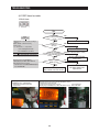
2) Simultaneous manual defrost(fresh food and freezer compartments) function
2-1) If any key is pressed one more time during manual operation(fresh food compartment), "Fd" shows in
the display and then manual operation will be canceled at once and fresh food and freezer
compartment will be defrosted.
2-2) At this moment, alarm beeps for 3 seconds (0.1 sec ON/ 1 sec OFF) during manual defrost function of
fresh food and freezer compartment.
3) Test cancel mode
3-1) During the simultaneous defrosting of fresh food and freezer compartments simultaneously, if the
display panel change to the test mode and test button is pressed one more time, defrosting of fresh
food and freezer compartments will be canceled at the same time and will return to the normal
operation. Or, all test functions will be canceled by turning main power OFF and ON.
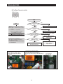
4-1-2. Display function of Communication error
1) Display function when Panel ↔ MAIN MICOM communication has error
1-1) If there is no answer for 10 seconds after the panel micom received the requirement of communication,
"Pc - Er" display on the panel PCB will be ON/OFF alternately until the communication error is
canceled. (0.5 sec ALL ON, 0.5 sec ALL OFF alternately)
1-2) “Pc - E” display on the Pantry Room Display will be ON/OFF alternately until the communication error
is canceled. (0.5 sec ALL ON, 1.5 sec ALL OFF alternately)
2) Display function when Panel ↔ MAIN MICOM OPTION has error
2-1) ”OP - Er” code is repeatedly ON/OFF until Option error settles down.
54
TROUBLESHOOTING
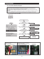
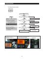
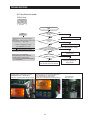
4-1-3. Self-diagnostic function
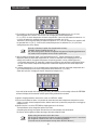
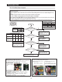
1) Self-diagnostic function in the Initial power ON
1-1) Micom operates self-diagnostic function to check the temperature sensor condition within 1 second
when the refrigerator turned On initially.
1-2) If bad sensor is detected by the self-diagnostic function, the applicable display LED will blink for 0.5
sec.
At this moment, there is no beep sound.(Refer to self-diagnostic CHECK LIST)
1-3) Self-diagnostic button is recognized only when the error is displayed by the bad sensor. Display does
not operate normally but temperature control will be controlled by the emergency operation.
1-4) When the error is detected by self-diagnosis, the error can be canceled automatically if all troubled
sensors are corrected or Self-diagnostic function key (Energy Saver Key + Lighting Key ) are pressed
simultaneously for 8 seconds.
(Return to normal display mode)
①
①
① If Energy Saver Key + Lighting Key are pressed simultaneously
for 8 seconds, the error mode by self-diagnosis will be canceled.
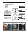
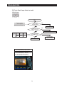
2) Self-diagnostic function during normal operation
①
①
① If Energy Saver Key + Lighting Key are pressed simultaneously
for 8 seconds, the error mode by self-diagnosis will be canceled.
2-1) If Energy Saver Key + Lighting Key are pressed simultaneously for 6 seconds during normal operation,
the temperature setting display will operate for 2 seconds (ON/OFF 0.5sec each).
If Energy Saver Key + Lighting Key are pressed simultaneously for 8 seconds (including above 2
seconds), self-diagnostic function will be selected.
2-2) At this moment, self-diagnostic function will be returned with buzzer sound 'ding-dong'.
If there is an error, display of error will be operated for 30 seconds and then return to normal condition
whether problem is corrected or not.
(Refer to self-diagnosis CHECK LIST)
2-3) Input by button is not accepted during self-diagnostic function.
55
TROUBLESHOOTING
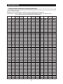
Self-diagnosis CHECK LIST
NO
1
2
3
4
5
6
7
8
9
10
11
12
13
14
15
16
17
18
19
20
Trouble item
Ice Maker Sensor Error(R)
R-Sensor Error
R-DEF-Sensor Error
R-FAN Error
Ice Maker operation Error(R)
R-DEF, Heater Error
Ambient-Sensor Error
F-Sensor Error
F-DEF-Sensor Error
F-FAN Error
C-FAN Error
Ice Room-Sensor Error
F-DEF.-Heater Error
Ice Room FAN Error
Pantry-Damper-Heater Error
Pantry-Sensor Error
Panel↔Main Micom Error
Water Tank-Heater Error
Ice Maker Sensor Error(F)
Ice Maker operation Error(F)
Display LED
R-1-ⓐ
R-1-ⓑ
R-1-ⓒ
R-1-ⓓ
R-1-ⓔ
R-1-ⓖ
F-1-ⓐ
F-1-ⓑ
F-1-ⓒ
F-1-ⓓ
F-1-ⓔ
F-1-ⓕ
F-1-ⓖ
F-10-ⓑ
R-10-ⓐ
R-10-ⓑ
F-10-ⓖ
R-10-ⓖ
R-10-ⓓ
R-10-ⓔ
F-10
F-1
Trouble contents
Senser system in ICE MAKER(R) errors
Sensor system in FF compartment errors
Defrost Sensor system in FF compartment errors
Fan motor system in FF compartment errors
ICE MAKER(R) operation system error
Defrost system in FF compartment errors
Snesor external system errors
Sensor system in FZ compartment error
Defrost Sensor system in FZ compartment errors
Fan motor system in FZ compartment errors
Fan motor system in machinery room errors
Sensor system in ICE ROOM errors
Defrost system in FZ compartment errors
Fan motor system in ICE ROOM errors
Damper Heater open/wire connection errors
Sensor system in Pantry Room errors
Communication between Panel MAIN MICOM error
Water Tank Heater open/wire connection errors
Senser system in ICE MAKER(R) errors
ICE MAKER(F) operation system error
R-10
R-1
56
TROUBLESHOOTING
Self-diagnostics check list
LED
Item
Trouble contents
The voltage of MAIN PCB CN30 #7↔CN76
#1:shall be between 4.5V~1.0V
R-1-ⓐ Ice Maker(R) Sensor Error
Display error : separation of sensor housing
R-10-ⓓ Ice Maker(F) Sensor Error part, contact error, disconnection, short
circuit
Display error of detecting temperature of
R-1-ⓑ
R-Sensor Error
sensor: more than 149℉ (+65°C) or less
than -58℉(-50°C)
R-1-ⓒ
R-DEF-Sensor Error
Display error during operation of applicable
fan motor : Feed Back signal line contact
error, separation of motor wire, motor error
Display error : ice making kit is harvested
R-1-ⓔ Ice Maker(R) operation Error more than 3 times and level error
** Apply to the applicable Ice Maker model.
ice making kit is harvested more than 3
R-10-ⓔ Ice Maker(F) operation Error times and level error
** Apply to the applicable Ice Maker model.
R-1-ⓓ
R-FAN Error
R-1-ⓖ
R-DEF. Error
F-1-ⓐ
Ambient-Sensor Error
F-1-ⓑ
F-Sensor Error
F-1-ⓒ
F-DEF-Sensor Error
F-1-ⓓ
F-FAN Error
F-1-ⓔ
C-FAN Error
F-1-ⓕ
Ice Room Sensor Error
F-1-ⓖ
F-DEF. Error
F-10-ⓑ
Ice Room-FAN Error
R-10-ⓐ
Pantry-Damper-Heater Error
R-10-ⓑ
Pantry-Sensor Error
Diagnostic method
Display error : separation of fresh food compartment defrost heater housing
part, contact error, disconnection, short circuit or temperature fuse error.
Display error : the defrosting does not finish though fresh food compartment
defrost is heating continuously for more than 80 minutes.
Display error : sensor housing separation,
contact error, disconnection, short circuit
Display error by detecting temperature of
sensor: more than 149℉(+65°C) or less
than -58℉(-50°C)
The voltage of MAIN PCB CN90 #8 ↔#4:
shall be between 4.5V~1.0V
The voltage of MAIN PCB CN30#6↔
CN76#1:shall be between 4.5V~1.0V
The voltage of MAIN PCB CN30#8↔
CN76#1:shall be between 4.5V~1.0V
Voltage of MAIN PCB CN76-4 Orange ↔ 1
Gray shall be between 7V~12V
After replacing ice maker, check the operation
by turning the appliance ON again.
After replacing ice maker, check the operation
by turning the appliance ON again.
After separating MAIN PCB CN70,CN71 from PCB, the resistance value
between CN70 White ↔ CN71 Orange shall be 110(441) ohm ± 7%.
(Resistant value is varied by the input power)
0 Ohm : heater short, ∞ Ohm : wire / bimetal Open.
The voltage of MAIN PCB
CN31#1↔#4 : shall be between 4.5V~1.0V.
The voltage of MAIN PCB CN30#3↔
CN76#1:shall be between 4.5V~1.0V
The voltage of MAIN PCB
CN30#4↔CN76#1:shall be between 4.5V~1.0V
Display error during operation of applicable
fan motor : Feed Back signal line contact
error, motor wire separation, motor error
Display error during operation of applicable
fan motor : Feed Back signal line contact
error, motor wire separation, motor error
Voltage of MAIN PCB CN76-3 Yellow ↔ 1
Gray shall be between 7V~12V.
Display error : sensor housing separation,contact error,
disconnection, short circuit.
Display error by detecting temperature of sensor: more
than 149℉ (+65°C) or less than -58℉ (-50°C)
Display error : separation of freezer compartment defrost heater housing
part , contact error, disconnection, short circuit or temperature fuse error.
Display error : the defrosting does not finish though fresh food compartment
defrost is heating continuously for more than 70 minutes.
The voltage of MAIN PCB
CN31#3 ↔CN76#1:shall be between 4.5V~1.0V
Voltage of MAIN PCB CN76-5 Sky-blue ↔ 1
Gray shall be between 7V~12V.
After separating MAIN PCB CN70,CN71 from PCB, resistant value
between CN70 brown ↔ CN71 Orange shall be 55(220) ohm ±
7%. (Resistant value is varied by input power)
0 Ohm : heater short, ∞ Ohm : wire / bimetal Open.
Display error during operation of applicable fan motor :
Voltage of MAIN PCB CN76-2 Black ↔ CN76-1 Gray : shall be
Feed Back signal line contact error, motor wire separation, between 6V~12V.
motor error
Display error when open error is detected by damper
heater : separation of Damper Heater housing part,
contact error, disconnection, short circuit
After separating MAIN PCB CN91from PCB, the resistant value
between Black ↔ brown wire shall be 145 ohm ± 7%.
0 Ohm : heater short, ∞ Ohm : wire / bimetal Open.
Display error : separation of sensor housing, contact error,
disconnection, short circuit.
Display error by detecting temperature of sensor: more than 149℉
(+65°C) or less than -58℉(-50°C)
The voltage of MAIN PCB
CN30#9 ↔ CN76#1 : shall be between 4.5V~1.0V.
R-10-ⓖ Water Tank-Heater Error
Display error when open error is detected by Water Tank After separating MAIN PCB CN79 from PCB, the resistant value
between pink ↔ white wire shall be 72 ohm ± 7%.
Heater : separation of Water Tank Heater housing
Check : 0 Ohm → heater short, ∞Ohm → wire / bimetal Open.
part,contact error, disconnection, short circuit
F-10-ⓖ Panel↔Main communication Error
Display “Pc - Er” in the panel with alarm : MICOM MAIN
PANEL communication error oP-Er is displayed when the
Option is not equivalent with the right value.
57
Actually, If there is not a problem, it is desirable to
replace Main and Panel PCB With the oscilloscope
after a cable problem confirming.
TROUBLESHOOTING
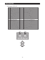
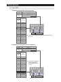
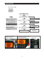
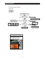
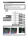
4-1-4. Display function of Load condition
①
①
②
① If Energy Saver Key + Lighting key are pressed simultaneously for 6 seconds, ALL ON/OFF will blink
with 0.5interval for 2 seconds.
② If take the finger off from above keys and press Fridge, load condition mode will be started.
1) If Power Energy Saver Key + Lighting key are pressed simultaneously for 6 seconds during normal
operation, the temperature setting display of fresh food and freezer compartments will blink ALL ON/OFF
with 0.5 for 2 seconds.
2) At this moment, If Fridge Key after Energy Saver Key + Lighting Key is pressed, load condition display
mode will be returned with alarm. At LED all on state, only load condition display will blink ON/OFF with
0.5 seconds interval.
3) Load condition display mode shows the load that micom signal is outputting.
However, It means that micom signal is outputting, it does not mean whether load is operating or not.
That is to say that though load operation is displayed, load could not be operated by actual load error or
PCB relay error etc. (This function would be applied at A/S.)
4) Load condition display function will maintain for 30 seconds and then normal condition will be returned
automatically.
5) Load condition display is as below.
F-10
F-1
R-10
R-1
58
TROUBLESHOOTING
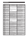
Load mode Check list
Display LED
R-1-ⓐ
R-1-ⓑ
R-1-ⓒ
R-1-ⓓ
R-1-ⓔ
R-1-ⓕ
F-1-ⓔ,ⓕALL LED Off
R1-ⓖ
F-1-ⓐ
F-1-ⓑ
F-1-ⓒ
F-1-ⓓ
R-10-ⓔ
R-10-ⓕ
F-1-ⓖ
F-10-ⓐ
F-10-ⓓ
F-10-ⓔ
R-10-ⓖ
R-10-ⓐ
F-10-ⓑ
R-10-ⓑ
Display contents
R-FAN High
R-FAN Low
R-DEF Heater
Start Mode
Overload condition
Low temperature condition
Normal Condition
Exhibition Mode
COMP.
F-FAN High
F-FAN Low
F-DEF Heater
C-FAN High
C-FAN Low
Dispenser Heater
Water Tank Heater
Ice Room-FAN High
Ice Room-FAN Low
French Heater
Pantry Room Damper Open
F-Valve Open
R-Valve Open
Operation contents
When FF compartment FAN operates with high speed, applicable LED ON
When FF compartment FAN operates with low speed, applicable LED ON
When FF compartment defrost heater operates, LED ON
When refrigerator is plugged initially, LED ON
When ambient temperature is more than 93℉(34°C), LED ON
When ambient temperature is less than 72℉(22°C), LED ON
When ambient temperature is between 73℉(23°C) and 91℉(33°C)
LED ON at the display mode.
When COMP operates, applicable LED ON.
When FZ compartment FAN operates with high speed, applicable LED ON.
When FZ compartment FAN operates with low speed, applicable LED ON.
When FZ compartment defrost heater operates, LED ON
When compressor FAN operates with high speed, applicable LED ON.
When compressor FAN operates with low speed, applicable LED ON.
When Dispenser Heater operates, applicable LED ON.
When Water Tank Heater operates, applicable LED ON.
When Ice Room-FAN operates with high speed, applicable LED ON.
When Ice Room-FAN operates with low speed, applicable LED ON.
When French heater operates, applicable LED ON
When damper open, applicable LED ON
When the F-valve open, LED ON
When the R-valve open, LED ON
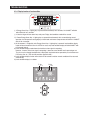
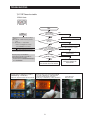
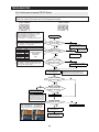
4-1-5. Exhibition mode setting function
①
①
① If Energy Saver Key + Freezer Key are pressed for 3 seconds, Exhibition mode will be started.
1) If Energy Saver Key + Freezer are pressed simultaneously for 3 seconds during normal operation,
Exhibition mode will be started with buzzer sound(ding-dong).
2) If above Energy Saver Key + Freezer Key are pressed one more time, Exhibitoin mode will be canceled.
3) If Exhibition mode is selected, blinks "OF-OF" on the temperature setting display of . The panel and it
indicates the refrigerator has entered the Cooling Off mode.
4) During Exhibition mode, if fresh food and freezer compartments sensors are higher than 149℉(65℃).
Exhibition will be canceled automatically and freezing operation will be returned.
(There is no buzzer sound when the Exhibition mode is canceled by the temperature.)
5) Operation contents of Exhibition Mode
- Display, Fan motor and etc operate normally, not to operate compressor only.
- Defrost is not operated. (including french heater)
- Display function of the initial real temperature is finished.
- Under the condition of Exhibition mode, Exhibition mode will be operated when Power On after Power
OFF.
59
TROUBLESHOOTING
4-1-6. Option setting function
● If Freezer Key+ lighting Key are pressed simultaneously for 12 seconds during normal operation, fresh
food and freezer compartments temperature display will be changed to option setting mode.
KEY operation method for changing to option mode
①
①
① If Freezer Key+ lighting Key are pressed simultaneously for 12 seconds, option setting mode will
be started.
KEY control method after converting to option mode
Code Down
Code Up
Reference Value Down
Code
Reference Value
Reference
Value Up
Key control in option mode
Energy Saver Key
Freezer Key
Lighting key
Fridge key
Code Down key
Code Up key
Reference Value down key
Reference Value Up key
● If the display changes to option setting mode, all displays will be off except freezer and fridge
compartments temperature display as below.
(Fresh food and freezer compartments case will be explained only because all options are operated with
the same method according to the option table.)
60
TROUBLESHOOTING
Code
Reference Value
1) For example, if you want to change freezer compartment standard temperature to -4℉(-2°C) by
operating option, do as below. This function is for changing the standard temperature.
In -2℉(-19°C) of current temperature of freezer compartment, if you make the temperature lower to -4℉
(-2°C) by the option, the standard temperature would be controlled -6℉(-21°C)
Therefore, if you change the setting of temperature option to -2℉(-19°C) on the panel, the appliance will
be operated with -6℉(-21°C). It means that standard temperature is controlled -4℉(-2°C) less than
setting temperature in the display.
NOTE
Basically, all the data in option has cleared from the factory.
Therefore, almost all setting value are "0".
But, some setting values could be changed for the purpose of improving performmance.
You need to check the product manual and/or specification.
2) After changing to the option mode, fresh food compartment "0" , freezer compartment "0" will be
displayed. ( Basically fresh food compartment "0", freezer "0" would be set at shipping process, but
setting value could be changed for the purpose of improving product at mass producing process.)
- If fresh food compartment "0" shows only, temperature reference value of freezer compartment will be
set and current freezer compartment temperature code will be displayed on the freezer temperature
display.
3) If freezer compartment "4" is set as below freezer compartment code after fresh food compartment "0 is
set, standard temperature of freezer compartment will be lower than -4℉(-2.0°C).
(Refer to the picture "changing the freezer compartment temperature")
Code
Reference Value
: If you wait for 20 seconds after completing the setting, MICOM will save the setting value to the EEPROM
and normal display will be returned and the option setting mode will be canceled.
4) Option changing method as above is the same as all RFG29** model.
5) By the same method as above, it is possible to control the fresh food compartment temperature, water
supply, ice-maker harvest temperature/time, defrost return time, hysteresis by temperature, notch gap by
temperature etc.
6) Option function is set in the EEPROM at shipping process in the factory.
You would better not to change the option of your own.
Completing the setting is that option function return to normal display after 20 seconds.
Do not turn off the appliance before returning to the normal display mode.
NOTE
Option setting function exists in the other items.
We will skip the explanation of the other functions by the option because it is associated
with refrigerator control function and is not needed at SERVICE.
(Please do not set the other options except above SERVICE Manual.)
61
TROUBLESHOOTING
4-1-7. Option TABLE
1) Temperature changing table of freezer compartment
Set item
Freezer Temp Shift
MODEL
RFG29*****
Reference
Value
Fridge Room 7-SEG
0
Setting value
FZ
compartment
Code
Temp.
compensation
0
0℉(0.0℃)
1
-1℉(-0.5℃)
2
-2℉(-1.0℃)
3
-3℉(-1.5℃)
4
-4℉(-2.0℃)
5
-5℉(-2.5℃)
6
-6℉(-3.0℃)
7
-7℉(-3.5℃)
8
+1℉(+0.5℃)
9
+2℉(+1.0℃)
10
+3℉(+1.5℃)
11
+4℉(+2.0℃)
12
+5℉(+2.5℃)
13
+6℉(+3.0℃)
14
+7℉(+3.5℃)
15
+8℉(+4.0℃)
Code
Reference Value
ex) If you want to change the freezer standard temperature to
-4℉(-2°C)
2) Temperature changing table of fresh food compartment
Set item
Freezer Temp Shift
MODEL
RFG29*****
Reference
Value
Fridge Room 7-SEG
1
Setting value
FZ
compartment
Code
Temp.
compensation
0
0℉(0.0℃)
1
-1℉(-0.5℃)
2
-2℉(-1.0℃)
3
-3℉(-1.5℃)
4
-4℉(-2.0℃)
5
-5℉(-2.5℃)
6
-6℉(-3.0℃)
7
-7℉(-3.5℃)
8
+1℉(+0.5℃)
9
+2℉(+1.0℃)
10
+3℉(+1.5℃)
11
+4℉(+2.0℃)
12
+5℉(+2.5℃)
13
+6℉(+3.0℃)
14
+7℉(+3.5℃)
15
+8℉(+4.0℃)
ex) If you want to change the
freezer compartment
standard temperature to
4℉(2°C)
Code
62
Reference Value
TROUBLESHOOTING
3) Temperature changing table of ICE ROOM compartment .
Set item
ICE ROOM Temp shift
MODEL
RFG29*****
Reference
Value
Fridge Room 7-SEG
20
Setting value
FZ
compartment
Code
Temp.
compensation
0
8.6℉(-13℃)
1
6.8℉(-14℃)
2
5℉(-15℃)
3
3.2℉(-16℃)
4
1.4℉(-17℃)
5
-0.4℉(-18℃)
6
-2.2℉(-19℃)
7
10.4℉(-12℃)
ex) If you want to change the
freezer compartment
standard temperature to
10.4℉(-12℃).
Code
Reference Value
4) Temperature changing table of Pantry Room compartment
- Could change the temperature of Pantry Room in fresh food compartment.
Set item
PANTRY ROOM Temp shift
MODEL
RFG29*****
Reference
Value
Fridge Room 7-SEG
33
Setting value
FZ
compartment
Code
Temp.
compensation
0
0℉(0.0℃)
1
-1℉(-0.5℃)
2
-2℉(-1.0℃)
3
-3℉(-1.5℃)
4
-4℉(-2.0℃)
5
-5℉(-2.5℃)
6
-6℉(-3.0℃)
7
-7℉(-3.5℃)
8
+1℉(+0.5℃)
9
+2℉(+1.0℃)
10
+3℉(+1.5℃)
11
+4℉(+2.0℃)
12
+5℉(+2.5℃)
13
+6℉(+3.0℃)
14
+7℉(+3.5℃)
15
+8℉(+4.0℃)
ex) If you want to change the
freezer compartment
standard temperature to
4℉(2°C).
Code
63
Reference Value
TROUBLESHOOTING
4-2) Diagnostic method according to the trouble symptom(Flow Chart)
DATA1.Temperature table
Resistance value and MICOM port voltage of sensor according to the temperature.
SENSOR CHIP : PX41C, 502AT// 103**(ICE MAKER SENSOR(MOLD))//FULL UP ,20K ohm used.
(The survey of resistance is nearly twice than below data.)
℃
℉
-50
-49
-48
-47
-46
-45
-44
-43
-42
-41
-40
-39
-38
-37
-36
-35
-34
-33
-32
-31
-30
-29
-28
-27
-26
-25
-24
-23
-22
-21
-20
-19
-18
-17
-16
-15
-14
-13
-12
-11
-10
-9
-8
-7
-6
-58
-56.2
-54.4
-52.6
-50.8
-49
-47.2
-45.4
-43.6
-41.8
-40
-38.2
-36.4
-34.6
-32.8
-31
-29.2
-27.4
-25.6
-23.8
-22
-20.2
-18.4
-16.6
-14.8
-13
-11.2
-9.4
-7.6
-5.8
-4
-2.2
-0.4
1.4
3.2
5
6.8
8.6
10.4
12.2
14
15.8
17.6
19.4
21.2
Voltage Resistance
4.694
4.677
4.659
4.641
4.622
4.602
4.581
4.560
4.537
4.514
4.490
4.465
4.439
4.412
4.385
4.356
4.326
4.296
4.264
4.232
4.199
4.165
4.129
4.093
4.056
4.018
3.980
3.940
3.899
3.858
3.816
3.773
3.729
3.685
3.640
3.594
3.548
3.501
3.453
3.405
3.356
3.307
3.258
3.208
3.158
153319
144794
136798
129294
122248
115631
109413
103569
98073
92903
88037
83456
79142
75077
71246
67634
64227
61012
57977
55112
52406
49848
47431
45146
42984
40938
39002
37169
35433
33788
32230
30752
29350
28021
26760
25562
24425
23345
22320
21345
20418
19537
18698
17901
17142
℃
℉
-5
-4
-3
-2
-1
0
1
2
3
4
5
6
7
8
9
10
11
12
13
14
15
16
17
18
19
20
21
22
23
24
25
26
27
28
29
30
31
32
33
34
35
36
37
38
39
23
24.8
26.6
28.4
30.2
32
33.8
35.6
37.4
39.2
41
42.8
44.6
46.4
48.2
50
51.8
53.6
55.4
57.2
59
60.8
62.6
64.4
66.2
68
69.8
71.6
73.4
75.2
77
78.8
80.6
82.4
84.2
86
87.8
89.6
91.4
93.2
95
96.8
98.6
100.4
102.2
Voltage Resistance
3.107
3.057
3.006
2.955
2.904
2.853
2.802
2.751
2.700
2.649
2.599
2.548
2.498
2.449
2.399
2.350
2.301
2.253
2.205
2.158
2.111
2.064
2.019
1.974
1.929
1.885
1.842
1.799
1.757
1.716
1.675
1.636
1.596
1.558
1.520
1.483
1.447
1.412
1.377
1.343
1.309
1.277
1.253
1.213
1.183
64
16419
15731
15076
14452
13857
13290
12749
12233
11741
11271
10823
10395
9986
9596
9223
8867
8526
8200
7888
7590
7305
7032
6771
6521
6281
6052
5832
5621
5419
5225
5039
4861
4690
4526
4369
4218
4072
3933
3799
3670
3547
3428
3344
3204
3098
℃
℉
40
41
42
43
44
45
46
47
48
49
50
51
52
53
54
55
56
57
58
59
60
61
62
63
64
65
66
67
68
69
70
71
72
73
74
75
76
77
78
79
80
81
82
83
84
104
105.8
107.6
109.4
111.2
113
114.8
116.6
118.4
120.2
122
123.8
125.6
127.4
129.2
131
132.8
134.6
136.4
138.2
140
141.8
143.6
145.4
147.2
149
150.8
152.6
154.4
156.2
158
159.8
161.6
163.4
165.2
167
168.8
170.6
172.4
174.2
176
177.8
179.6
181.4
183.2
Voltage Resistance
1.153
1.124
1.095
1.068
1.040
1.014
0.988
0.963
0.938
0.914
0.891
0.868
0.846
0.824
0.803
0.783
0.762
0.743
0.724
0.706
0.688
0.670
0.653
0.636
0.620
0.604
0.589
0.574
0.560
0.546
0.532
0.519
0.506
0.493
0.481
0.469
0.457
0.446
0.435
0.424
0.414
0.404
0.394
0.384
0.375
2997
2899
2805
2714
2627
2543
2462
2384
2309
2237
2167
2100
2036
1973
1913
1855
1799
1745
1693
1642
1594
1547
1502
1458
1416
1375
1335
1297
1260
1225
1190
1157
1125
1093
1063
1034
1006
978
952
926
902
877
854
832
810
TROUBLESHOOTING
4-2-1. If the trouble is detected by self-diagnosis
- The error of sensor will be displayed on the front of display.
When the error of sensor is detected at initial power ON, the appliance will operated by the
emergency mode and display of abnormal sensor part will blink.
- The appliance will not stop operating when the error of sensor is detected during operation of the
appliance.
But normal freezing might be not operated if the appliance is operated by the emergency operation
mode. You would better to check the appliance according to the self-diagnosis of the manual.
1) If ICE Maker(R) Sensor has troubled
ERROR Code
Start
DATA1.
Temperature table
** Measuring point of resistance value according to
Sensor **
ICE MAKER(R) : CN30#7 ↔#4 measuring resistance value
** 0Ω: Short trouble / ∞Ω: Open trouble
Is MAIN PCB Connector
CN30 inserted correctly?
YES
Is ICE Maker(R) Sensor
unit normal?
Refer to circuit diagram in the manual
Sensor MICOM/Connector number
ICE
Connector CN30-"7"(Brown) and
Maker(R) REG1 HEAT-SINK PCB common Ground
Voltage measured between 4.6V ~ 0.6V.
NO
Bad contact of connector/ insert correctly
NO
Replace the temperature sensor
YES
Is the voltage between
MAIN PCB Connector CN30#"7"(Brown) and
REG1, HEAT SINK normal?
NO(0.6V > Measurement < 4.6V)
YES
Measuring voltage of IC01 MICOM #75,
CN30-"7"(Brown) and REG1, HEAT SINK from
PCB typical Ground part are similar.
→ Check the measure on the SENSOR MARKING #4(R312)
due to the SMD MICOM
Is input voltage of IC01
MICOM #75 normal?
NO
YES
No trouble with PCB and temperature sensor.
Recheck the bad contact of the connection.
☞ Checking Method of ICE MAKER(R) Senser resistance CN30
#7(Brown) ↔ CN76 #1"(Gray)
- Compare the temperature table after the measure.
☞ Checking method of ICE Maker(R) Sensor voltage
- Measure the voltage of Sensor Check Point #4(IC01 MICOM #75) or
CN30#7(Brown) ↔ REG1, HEAT SINK.
- Compare the temperature table after the measure. Measuring voltage
of CN30#4(Brown) ↔ REG1, HEAT SINK are below.
65
Check the contact of PCB & Wire
Terminal correctly.
Check the iced-solder, solder bridging,
disturbed solder.
Replace the PCB
typical PCB Ground
REG1 HEAT-SINK
TROUBLESHOOTING
2) If ICE Maker(F) Sensor has troubled
ERROR Code
※ This refrigerator has Dual Ice Maker,
so controlled two Ice Makers.
Start
DATA1.
Temperature table
** Measuring point of resistance value according to Sensor **
ICE MAKER(F) : CN90 #3 or #8 ↔ #4 measuring
resistance value
** 0Ω: Short trouble / ∞Ω: Open trouble
Is MAIN PCB
Connector CN90 inserted
correctly?
YES
Is ICE Maker(F)
sensor unit normal?
Refer to circuit diagram in the manual
Sensor MICOM/Connector number
ICE Connector CN90-#4(White) and REG1
HEAT-SINK PCB common Ground
Maker(F)
Voltage measured between 4.6V ~ 0.6V.
NO
Bad contact of connector/ insert correctly
NO
Replace the ICE Maker
YES
Is the voltage between
MAIN PCB Connector CN90#"4"(White)
and REG1, HEAT SINK normal?
NO(0.6V > Measurement < 4.6V)
YES
Measuring voltage of IC01 MICOM #78,
CN90#4(White) and REG1, HEAT SINK from PCB
typical Ground part are similar.
→ Check the measure on the SENSOR MARKING #9(R901)
due to the SMD MICOM.
Is input voltage of
IC01 MICOM #78 normal?
NO
YES
No trouble with PCB and temperature sensor.
Recheck the bad contact of the connection.
☞ Checking Method of ICE MAKER(R) Senser
resistance CN90 #3(white) or #8(Sky_blue) ↔
#4(White)
- Compare the temperature table after the measure.
☞ Checking method of ICE Maker(F) Sensor voltage
- Measure the voltage of Sensor Check Point #9(IC01 MICOM
#78) or CN90#4(white) ↔ REG1, HEAT SINK.
- Compare the temperature table after the measure.
Measuring voltage of CN90#4(White) ↔ REG1, HEAT SINK
are below.
66
Check the contact of PCB & Wire
Terminal correctly.
Check the iced-solder, solder bridging,
disturbed solder.
Replace the PCB
typical PCB Ground
REG1 HEAT-SINK
TROUBLESHOOTING
3) If R Sensor has trouble
ERROR Code
Start
DATA1.
Temperature table
Is MAIN PCB
Connector CN30 and CN76 inserted
correctly?
YES
** Measuring point of resistance value according to
Sensor **
R : CN30#6 ↔ CN76#1 measuring resistance value
** 0Ω: Short trouble / ∞Ω: Open trouble
Is R Sensor
unit normal?
Refer to circuit diagram in the manual
Sensor MICOM/Connector number
Connector
CN30#6(White) to
R
REG1 HEAT-SINK PCB typical Ground
Voltage measured between 4.6V ~ 0.6V.
NO
Bad contact of connector/ insert correctly
NO
Replace the temperature sensor
YES
Is the voltage between
MAIN PCB Connector CN30#6(White) and
REG1 HEAT-SINK normal?
NO(0.6V > Measurement < 4.6V)
YES
Measuring voltage IC01 MICOM #76,
CN30#6(White) and REG1, HEAT SINK
from PCB typical Ground part are similar.
→ Check the measure on the SENSOR MARKING #3(R311)
due to the SMD MICOM
Is the input voltage of
IC01 MICOM #76 normal?
NO
YES
No trouble with PCB and temperature sensor.
Recheck the bad contact of the connection.
☞ Checking method of R Sensor resistance
CN30#6(White) ↔ CN76#1(Gray) Compare the
temperature table after measurment.
☞ Checking method of R Sensor resistance
- Measure the voltage of Sensor Check Point #3(IC01 MICOM
#76) on PCB or CN30#6(White) ↔ REG1, HEAT SINK
- Compare the temperature table after measurement.
Measuring voltage of CN30#6(White) ↔REG1, HEAT SINK
are as below.
67
Check the contact of PCB & Wire
Terminal correctly.
Check the iced-solder, solder bridging,
disturbed solder.
Replace the PCB
Typical PCB Ground
REG1, HEAT SINK
TROUBLESHOOTING
4) If R DEF Sensor has trouble
ERROR Code
Start
DATA1.
Temperature table
Is MAIN PCB
Connector CN30 and CN76 inserted
correctly?
YES
** Measuring point of resistance value according to
Sensor **
R-DEF : CN30#8 ↔ CN76#1 measuring
resistance value
** 0Ω: Short trouble / ∞Ω: Open trouble
Is R DEF Sensor
unit normal?
Refer to circuit diagram in the manual
Sensor MICOM/Connector Number
Connector
CN30-"8"(Sky-blue) and
R DEF REG1, HEAT
SINK PCB common Ground
Voltage measured between 4.6V ~ 0.6V.
NO
Bad contact of connector/ insert correctly
NO
Replace the temperature sensor
YES
Is the input voltage between
MAIN PCB Connector CN30#8(Skyblue)
and REG1, HEAT SINK normal?
NO(0.6V > Measurement < 4.6V)
YES
Measuring voltage of IC01 MICOM #74,
CN30#8(Sky-blue) and REG1, HEAT SINK from
PCB typical Ground part are similar.
→ Check the measure on the SENSOR MARKING #5(R313)
due to the SMD MICOM
Is the input voltage of IC01
MICOM # 74 normal?
NO
YES
No trouble with PCB and temperature sensor.
Recheck the bad contact of the connection.
☞ Checking method of R Sensor resistance
CN30#8(Sky-blue) ↔ CN76#1(Gray)
- Compare the temperature table after
measurement.
Check the contact of PCB & Wire
Terminal correctly.
Check the iced-solder,
solder bridging, disturbed solder.
Replace the PCB
☞ Checking method of R DEF Sensor resistance
- Measure the voltage of Sensor Check Point #5(IC01 MICOM #74) on PCB or
CN30#8(Sky-blue)↔REG1, HEAT SINK
- Compare the temperature table after measurement.
Typical PCB Ground
Measuring voltage of CN30#8(Sky-blue) ↔ REG1, HEAT SINK are as below. REG1, HEAT SINK
68
TROUBLESHOOTING
5) If Ambient Sensor has trouble
ERROR Code
Start
DATA1.
Temperature table
** Measuring point of resistance value according to
Sensor **
Ambient : CN31#1 ↔ #4 measuring resistance value
** Placed in the right top table of upper hinge.
** 0Ω: Short trouble / ∞Ω: Open trouble
Is MAIN PCB
Connector CN31 inserted
correctly?
YES
Is Ambient Sensor
unit normal?
Refer to circuit diagram in the manual
Sensor MICOM/Connector number
Connector
CN31#1(Yellow) to
Ambient REG1, HEAT-SINK
PCB typical Ground
Voltage measured between 4.6V ~ 0.6V.
NO
Bad contact of connector/ insert correctly
NO
Replace the temperature sensor
YES
Is the voltage between
MAIN PCB Connector CN31#1(Yellow)
and REG1, HEAT SINK normal?
NO(0.6V > Measurement < 4.6V)
YES
Measuring voltage of IC01 MICOM #72,
CN31#1(Yellow) and REG1, HEAT SINK from
PCB typical Ground part are similar.
→ Check the measure on the SENSOR MARKING #7(R307)
due to the SMD MICOM
Is the input voltage of
IC01 MICOM #72 normal?
NO
YES
No trouble with PCB and temperature sensor
Recheck the bad contact of the connection
☞ Checking method of Ambient Sensor resistance
CN31#1(Yellow) ↔ #4(Yellow)
- Compare the temperature table after
measurement.
☞ Checking method of Ambient Sensor voltage
- Measure the voltage of Sensor Check Point #7(IC01 MICOM #72)
on PCB or CN31#1(Yellow) ↔ REG1, HEAT SINK
- Compare the temperature table after measurement.
Measuring voltage of CN31#1(Yellow) ↔ REG1, HEAT SINK are as
below
69
Check the contact of PCB & Wire
Terminal correctly.
Check the iced-solder,
solder bridging, disturbed solder.
Replace the PCB
Typical PCB Ground
REG1 Heater Sink
TROUBLESHOOTING
6) If F Sensor has trouble
ERROR Code
Start
DATA1.
Temperature table
Are MAIN PCB
Connector CN30 and CN76
inserted correctly?
YES
** Measuring point of resistance value according to
Sensor **
F : CN30#3 ↔ CN76#1 measuring resistance value
** 0Ω: Short trouble / ∞Ω: Open trouble
Is F Sensor
unit normal?
Refer to circuit diagram in the manual
Sensor MICOM/Connector number
Connector
CN30#3(Red) to
F
REG1, HEAT SINK PCB typical Ground
Voltage measured between 4.6V ~ 0.6V.
NO
Bad contact of connector/ insert correctly
NO
Replace temperature sensor
YES
Is the voltage between
MAIN PCB Connector CN30#3(Red) and
REG1, HEAT SINK normal?
NO(0.6V > Measurement < 4.6V)
YES
Measuring voltage of IC01 MICOM #81,
CN30#3(Red) and REG1, HEAT SINK from
PCB typical Ground part are similar.
→ Check the measure on the SENSOR MARKING #1(R309)
due to the SMD MICOM
Is the input voltage of
IC01 MICOM #81 normal?
NO
YES
No trouble with PCB and temperature sensor
Recheck the bad contact of the connection
☞ Checking method of F Sensor resistance
CN30#3(Red) ↔ CN76#1(Gray)
- Compare the temperature table after measurement.
☞ Checking method of F Sensor voltage
- Measure the voltage of Sensor Check Point #1(IC01 MICOM #81) on
PCB or CN30#3(Red) ↔ REG1, HEAT SINK
- Compare the temperature table after measurement.
Measuring voltage of CN30#3(Red) ↔ REG1, HEAT SINK are as
70
Check the contact of PCB & Wire
Terminal correctly.
Check the iced-solder,
solder bridging, disturbed solder.
Replace the PCB
Typical PCB Ground
REG1 Heater Sink
TROUBLESHOOTING
7) If F DEF Sensor has trouble
ERROR Code
Start
DATA1.
Temperature table
Are MAIN PCB
Connector CN30 and
CN76 insert correctly?
YES
** Measuring point of resistance value according to
Sensor **
F-DEF : CN30#4 ↔ CN76#1 measuring resistance
value
** 0Ω: Short trouble / ∞Ω: Open trouble
Is F DEF Sensor
unit normal?
Refer to circuit diagram in the manual
Sensor MICOM/Connector number
Connector
CN30#4(Orange) to
F DEF REG1, HEAT
SINK PCB typical Ground
Voltage measured between 4.6V ~ 0.6V.
NO
Bad contact of connector/ insert correctly
NO
Replace temperature sensor
YES
Is the voltage between
MAIN PCB Connector CN30#4(Orange) and
REG1, HEAT SINK normal?
NO(0.6V > Measurement < 4.6V)
YES
Measuring voltage of IC01 MICOM #77,
CN30#4(Orange) and REG1, HEAT SINK from
PCB typical Ground part are similar.
→ Check the measure on the SENSOR MARKING #2(R310)
due to the SMD MICOM
Is the input voltage of
IC01 MICOM #77 normal?
NO
YES
No trouble with PCB and temperature sensor.
Recheck the bad contact of the connection.
☞ Checking method of F DEF Sensor resistance
CN30#4(Orange) ↔ CN76#1(Gray)
- Compare the temperature table after measurement.
☞ Checking method of F DEF Sensor voltage
- Measure the voltage of Sensor Check Point #2(IC01 MICOM
#77) on PCB or CN30#4(Orange) ↔ REG1, HEAT SINK
- Compare the temperature table after measurement.
Measuring voltage of CN30#4(Orange) ↔ REG1, HEAT SINK are
71
Check the contact of PCB & Wire
Terminal correctly.
Check the iced-solder,
solder bridging, disturbed solder.
Replace the PCB
Typical PCB Ground
REG1, Heater Sink
TROUBLESHOOTING
8) If Ice Room Sensor has trouble
ERROR Code
Start
DATA1.
Temperature table
** Measuring point of resistance value according to
Sensor **
Ambient : CN32#3 ↔ CN76#1 Measure the resistance
value
** 0Ω: Short trouble / ∞Ω: Open trouble
Is MAIN PCB
Connector CN31 and CN76 inserted
correctly?
YES
Is Ice Room Sensor
unit normal?
Refer to the circuit diagram in this manual
Sensor MICOM/Connector number
Connector
and REG1,
Ice Room HEAT SINKCN31-”3”(Orange)
from typical PCB Ground
Voltage measured between 4.6V ~ 0.6V.
NO
Bad contact of connector/ insert correctly
NO
Replace temperature sensor
YES
Is the voltage between
MAIN PCB Connector CN31-”3”(Orange)
and REG1, HEAT SINK normal?
NO(0.6V > Measurement < 4.6V)
YES
Measuring voltage of IC01 MICOM #71,
CN31-”3”(Orange) and REG1, HEAT SINK from
typical PCB Ground are similar.
→ Check the measure on the SENSOR MARKING #8(R308)
due to the SMD MICOM
Is the input voltage of
IC01 MICOM #71 normal?
NO
YES
No trouble with PCB and temperature sensor.
Check the bad connections.
☞ Checking Mehod of Ice Room Sensor voltage
CN31-”3”(Orange) ↔ CN76-”1” (Gray)
- Compare with the temperature table after
measurement.
☞ Checking Method of Ice Room Sensor Voltage
- Measure the voltage of sensor checking point #8(IC01 MICOM #71) on
PCB or CN31-”3” (Orange) ↔ REG1, HEAT SINK
- Compare with the temperature table after measurement.
Measured voltage of CN31-”3” (Orange) ↔ REG1, HEAT SINK are as
below
72
Check the contact of PCB & Wire
Terminal correctly.
Check the iced-solder,
solder bridging, disturbed solder.
Replace the PCB
Typical PCB Ground
REG1, HEAT SINK
TROUBLESHOOTING
9) If Pantry Sensor has trouble
ERROR Code
Start
DATA1.
Temperature table
Is MAIN PCB
Connector CN30 and CN76 insert
correctly?
YES
** Measuring point of resistance value according to
Sensor **
Pantry : CN30#9 ↔ CN76 #1 measuring resistance value
** 0Ω: Short trouble / ∞Ω: Open trouble
Is Pantry Sensor
normal?
Refer to circuit diagram in the manual
Sensor MICOM/Connector number
Connector
CN30#9(White-black) to
Pantry REG1 HEAT
SINK PCB typical Ground
Voltage measured between 4.6V ~ 0.6V.
NO
Bad contact of connector/ insert correctly
NO
Replace temperature sensor
YES
Is the voltage between
MAIN PCB Connector CN30#9(Whiteblack)
and REG1, HEAT SINK normal?
NO(0.6V > Measurement < 4.6V)
YES
Measuring voltage of IC01 MICOM #73,
CN30#9(White-black) and REG1, HEAT SINK
from PCB typical Ground part are similar.
→ Check the measure on the SENSOR MARKING #6(R314)
due to the SMD MICOM
Is the input voltage of IC01
MICOM Pin# 73 normal?
NO
YES
No trouble with PCB and temperature sensor.
Recheck the bad contact of the connection.
☞ Checking method of Pantry Sensor resistance
CN30#9(White-black) ↔ CN76#1(Gray)
- Compare the temperature table after measurement.
☞ Checking method of Pantry Sensor voltage
- Measuring voltage of Sensor Check Point #6(IC01 MICOM #73) on
PCB or CN30#9(White-black) ↔ REG1, HEAT SINK
- Compare the temperature table after measurement.
Measuring voltage of CN30#9(white-black)↔REG1, HEAT SINK are
73
Check the contact of PCB & Wire
Terminal correctly.
Check the iced-solder,
solder bridging, disturbed solder.
Replace the PCB
Typical PCB Ground
REG1 Heater Sink
TROUBLESHOOTING
10) If Pantry Room Damper Heater has trouble
ERROR Code
Start
Measure the resistance
between ①-② after
CN91 connector open 145ohm ± 7%
Is Damper Heater
normal?(about145ohm)
NO
YES
Is MAIN PCB connector
(CN91) inserted correctly?
Replace Damper
NO
Bad contact of connector/ insert correctly
YES
Initial
Damper Damper
MICOM power On heater off heater On
#42
3.5V ~
condition 3.5V ~
0V
4.8V
4.8V
Is the input voltage of
IC02 MICOM #42 normal?
YES
Normal(recheck)
※ It could changed HEATER capacity by operation.
☞ Checking method of Pantry Room Damper
resistance CN91#1(Black) ↔ #2(Brown)
** ∞Ω: Open(wire disconnection, heater
disconnection) trouble / 0Ω: Short trouble
74
NO
1) Recheck the wire
2) Replace PCB MAIN
TROUBLESHOOTING
11) If Tank Water Heater has trouble
ERROR Code
Start
Is MAIN PCB connector
(CN79) inserted correctly?
NO
YES
Measure the resistance
between ⑥(3)-⑩(7) after
CN79 connector open 72ohm ± 7%
Is Tank Water Heater
normal?(about72ohm)
Bad contact of connector/ insert correctly
NO
YES
Working
Initial
MICOM power On Heater off heater
#6
3.5V ~
condition 3.5V ~
0V
4.8V
4.8V
Is the input voltage of
IC01 MICOM #6 normal?
YES
Normal(recheck)
※ It could changed HEATER capacity by operation
☞ Checking method of Tank Water Heater
resistance CN79#6(Pink) ↔ #10(White)
** ∞Ω: Open(wire disconnection, heater
disconnection) trouble / 0Ω: Short trouble
75
NO
1) Wire connector
2) Replace Heater
1) Recheck the wire
2) Replace PCB MAIN
TROUBLESHOOTING
4-2-2. IF FAN does not operate(F, R, C - FAN)
- The refrigerator of this model has BLDC FAN motor. BLDC motor is driven by DC 7~12V.
- On the normal condition of COMP ON, it operates together with F-FAN motor.
If door is opened and closed once at a high ambient temperature, it will be operated after 1 minute
delay.
Therefore, you are advised not to taken it for an error.
-. If there is a trouble, you should select the self-diagnostic function to check the trouble before power off.
Start
Is COMPRESSOR ON ?
Excute manualoperation.
If initial temperature of F Room
is under the 41℉ (5℃), waitng
7 minutes and then activate.
Is the voltage between MAIN
PCB REG1, HEAT SINK and
CN76#5(Sky -blue) around DC7~12V?
Is the voltage between MAIN
PCB REG1,Heater Sink and CN76#4
(Orange) around DC7~12V?
Is the voltage between MAIN
PCB REG1 Heater Sink and CN76#3
(Yellow) around DC7~12V?
FAN work normally
Is the voltage between MAIN
PCB REG1,Heater Sink and
CN30#2 (Purple) around 0V?
Is the external temperature above
66.2 ℉(19℃ )?
Is the voltage between MAIN
PCB REG1 Heater Sink and CN30#1
(Black) around 4.5~5V?
Repair the connection
of Door switch
Recheck after 7 minutes
(Time could be delayed
depending on the
temperatures. If the
temperature is lower, It
may not operate : about
59℉ (below 15℃)
Door & MICOM State
F
R MICOM(#82)
Door MICOM
Right and Left
(#83)
Close 5V(High)
Open 0V(Low)
Does DC7~12V alternate with below
DC 2V between MAIN PCB REG1 Heater
Sink and CN76#5(Sky-blue)
0V(Low)
5V(High)
Power on with about 7
minutes delay after power
OFF. (For preventing the
over load of compressor)
Does DC7~12V alternate with below
DC 2V between MAIN PCB REG1 Heater
Sink and CN76#4(Orange)
In initial power to appliance, the compressor
and fans of fresh food/ freezer, compressor
fan operate. If freezer temperature is
sensed of 41℉ by momentary power
failure, fans will operate after 5 minutes.
Does DC7~12V alternate with
below DC 2V between MAIN PCB REG1
Heater Sink and CN76 #3(Yellow)
Replace MAIN PCB
F FAN pulse voltage
CN76#7(Brown)
Typical PCB Ground
REG1 Heater Sink
The voltage measured around 2~3V
with multi-meter though the voltage is
very weak because of pulse signal
Reference
CN76-7(F),8(R),9(C)will generate the pulse signal when motor rotates.
These signals will be inputted into MICOM.
Unless signals are not inputted during motor operating, will be ON 10
seconds after fan Off. But if signals are not still entered, the above operation
will restart four times more.
If signals are not entered continuously, the motor will be restarted after 10
seconds.
This function is effective when the normal operation of motor would be
restrained by foreign matters such as ice.
☞ Display for checking the self-diagnostic function
R FAN ERROR
F FAN ERROR
◆ Expected causes
① Check that if FAN-MOTOR has failure
itself.
② Check that if wiring connection has bad
contact.
③ Check the input of the fan motor rotation
pulse when motor fan operates.
☞ Checking method of R,F,C FAN Motor voltage
The voltage between PCB typical Ground REG1 Heater Sink and
F FAN ; CN76#3(Yellow) shall be less than DC 7~12V.
R FAN ; CN76#4(Orange) shall be less than DC 7~12V.
C FAN ; CN76#5(Sky-blue) shall be less than DC 7~12V.
- Motor rpm could be changed by capability without previous.
1) F-FAN
C FAN ERROR
76
2) R-FAN
Typical PCB Ground
REG1 Heater Sink
3) C-FAN
TROUBLESHOOTING
4-2-3. If ICE Room Fan does not operate
- This refrigerator has BLDC FAN motor. BLDC motor is driven by DC7~12V.
- When COMP ON, normally operates with F-FAN motor.
- If there is any trouble, you should select the self-diagnostic function to check the trouble before power off.
Start
- When pressing the ICE TEST S/W for a certain period of time
(over 1.5sec), the function is accomplished. After beginning of
TEST mode, Ice maker heater turns on for initial 2 minutes, if the
ice making temperature is below 0℃.
- If it exceeds 0℃, Ice maker heater turns on for initial 30 seconds.
- After Ice maker heater turns on for 30 seconds, it turns off and
then Ice maker motor turns on.
- As the Ice maker motor turns on, TEST MODE COUNT operates.
(6 minutes count)
Condition
- Ambient temperature : 32℃/75%
- Notch : 2℉/38℉(-19.0℃/3.3℃)
Initial full of ice bucket capacity : 794 g, 58ea
Is COMPRESSOR ON ?
Yes
Is the voltage between
MAIN PCB REG1 Heater Sink and
CN76-”2” (Black) around
DC7~12V?
No
Ice Room control temperature
Ice ON
8.6℉(-13℃)
Ice OFF
26.6℉(-3℃)
Is the Ice Room
temperature suitable for
the Fan working?
Yes
No
Execute manual operation
Yes
FAN works normally
No
Operation
temperature/ready
Reference
CN76 #6 will generate the pulse signal when motor rotates.
These signals will be input into MICOM.
Unless signals are not input during motor operating, will be ON
10seconds after fan OFF. But if signals are not still taken, the
above operation will be retried four times more. If signals are not
taken continuously, the motor will be restarted after 10 minutes.
This function is against the case that motor movement would be
restrained by foreign matters like ice.
FAN pulse voltage
CN76-”6”(Pink)
☞ Display for checking the self-diagnostic function
Yes
No
Replace MAIN PCB
◆ Predicted Cause
① FAN-MOTOR troubles itself
② Bad wiring connections.
③ Wrong Input of the fan motor rotation pulse
Typical PCB Ground
REG1 Heater Sink
The voltage is variable due to pulse
signal but measured about 2~3V with the
Multi-Meter.
Does DC7~12V alternate
with below DC2V between MAIN PCB REG1
Heater Sink and CN76-”2”(Black)?
☞ Checking method of Ice Room FAN Motor Voltage with the voltage between typical
PCB Ground REG1 Heater Sink and Ice Room FAN ; CN76-”2”(Black) shall be less
than DC 6~12V.
- Additional check if resistance values are different after measurement.
1) Ice Room - FAN
Ice Room FAN ERROR
Typical PCB Ground
REG1 Heater Sink
77
TROUBLESHOOTING
4-2-4. If Ice Maker does not operate
1. Water is automatically supplied to the Ice Maker depending on temperature & time condition and Ice Maker Dispenses
cubed or crushed ice.
2. Power is applied to the one end of wires. Be careful when disassembling and shall refer to its exploded diagram in any
case.
3. Ice Maker operation shall be checked after pressing the Ice Maker testing switch.
(Freezer Ice Maker) It is not possible to check when the power is disengaged.
4. We recommend that TWO PEOPLE check the PCB and Ice Maker because they are located at front and rear side each.
5. Be careful! The Ice Maker Heater can cause personal injury like burn.
6. Ice maker could operate not only genuine rotate but also reverse rotate, so it is not out of order that reverse rotate.
Operating Condition when motor rotates
Operating Status of Micom(IC01)
Displays ERROR Code
Motor Load (#56)
Heater Load (#57)
Heater Load (#67)
Start
MICOM(IC02) Operation Status
#05
Operation Ready
(Test Switch)
5V
0V
Does Ice Maker
rotate when pressing the Ice Maker
testing switch(over 1.5 sec)?
Yes
#111
(Blade Ice Scoop)
0V
#38
(Guide Ice Full)
0V
4.9V
4.9V
Is the input voltage of IC01
MICOM #38,#111 normal?
0V
4.9V
0V
State of Ice maker operation
Levelness sensinfg → water
supply → Motor reverse rotate
→ return to normal → normality
Heater operates differently according to the conditions.
Test Mode operation will be 30 sec.
No
1) Check the wiring connections.
2) Replace Ice Maker Kit
3) Replace MAIN PCB
Yes
0V
Operation
5V
5V
5V
1) Replace the Ice Maker Kit
2) Check/Replace the Main PCB
input signal
(Micom IC01 Pin #05 - “0V”)
MICOM(IC01) Operation Status
Before Returning
Ready Rotation Complete
No
Ready
0V
0V
0V
Is the water supplied in 6
minutes (After sensing ice bucket
fully)?
No
1) Replace the Water Valve
* Refer to the operation
condition of Water Valve
2) Replace the Main PCB
Yes
Is the Ice Maker Sensor unit normal?
Yes
No
1) Repair the Ice Maker Sensor
* Refer to the solution “If Ice
Maker Sensor has trouble”
No trouble with PCB and temperature sensor,
Check the bad wiring connections.
☞ Checking Method of ICE Maker Voltage
With typical PCB Ground REG1 Heater Sink and
1) Test Switch operation (press selected) : CN75-”5” (Black) shall be DC 0V.
Test Switch ready ; CN75-”5” (Black) shall be less than DC 5V.
a)Test Switch operating b)Test Switch ready
- When the refrigerator
operate, the voltage is
0V.
☞ Check the ICE Maker Heater & Motor Resistance
1) Measuring the Ice Maker Heater
resistance values
Typical PCB Ground
REG1 Heater Sink
☞ Checking Method of ICE Maker Voltage
With typical PCB Ground REG1 Heater Sink and
2) IC01 MICOM #111 voltage ; Ready(0V) → Rotate (4.9V) → Before
complete(4.9V) → Return(0V)
* MICOM #111 voltage is same as Connector CN50-”11”(Sky-Blue)
3) IC02 MICOM #38 voltage ; Ready(0V) → Rotate (0V) → Before
complete(4.9V) → Return(0V)
* MICOM #38 voltage is same as Connector CN90-”6”(Blue)
78
2) Measuring the Ice Maker Motor
resistance values
CN70-"11"(Gray) -"1"(Black)
CW: 13P-"11"(White) and CN70-"9"(Red)
CCW: 13P-"13"(Pink) and CN70-"9"(Red)
Resistance value : 91(365)Ohm± 10%
Resistance value : 200KOhm± 30%
TROUBLESHOOTING
4-2-5. If ICE MAKER(F) does not operate
1. Water is automatically supplied to the Ice Maker depending on temperature & time condition and Ice
Maker Dispenses cubed or crushed ice.
2. Power is applied to the one end of wires. Be careful when disassembling and shall refer to its
exploded diagram in any case.
3. Ice Maker operation shall be checked after pressing the Ice Maker testing switch.
(Freezer Ice Maker) It is not possible to check when the power is disengaged.
4. We recommend that TWO PEOPLE check the PCB and Ice Maker because they are located at front
and rear side each.
ERROR Code
Start
Is the checking location by
self sensing when initial Power ON?
NO
YES
Micom(IC01) Operation Status
#37
Ready Operation
(Test Switch)
5V
0V
1) Check the wiring connections
Does ice
NO 2) Check/Replace the Ice Maker kit.
Maker Rotate when pressing the Ice Maker
testing switch?
YES
Micom(IC01) Operation Status
Ready Rotation
#39
5V
0V
Is the input voltage of IC01
MICOM #39 normal?
Before Returning Ready
Complete
5V
0V
5V
YES
Is the water
supplied in 6 minutes(After sensing ice
bucket fully?
YES
Is the ice Maker Sensor
unit normal?
1) Check/Replace the Ice Maker kit.
NO
1) Check the wiring connections
2) Check/Replace the Ice Maker kit.
NO 3) Check/Replace the main PCB
1) Replace the Water Valve
*
NO Refer to the operation condition of Water valve
No trouble with PCB and temperature sensor,
Check the bad wiring connections.
☞ Checking Method of ICE Maker Voltage With typical PCB Ground REG1 Heater Sink and
1) Test Switch operation(press selected) ; CN90-"5"(Gray) shall be DC 0V.
Test Switch ready ; CN90-"5"(Gray) Shall be less than DC 5V.
1) Test Switch operating
1) Test Switch ready
1) Repair the ice Maker
* Refer to the solution If ice Maker Sensor has
trouble.
typical PCB Ground
REG1 HEAT-SINK
☞ Checking Method of ICE Maker Voltage With typical PCB Ground REG1 Heater Sink and
2) IC01 MICOM #39 voltage ; Ready(0V) → Rotate(0V) → Before complete(5V) → Return(0V) → Ready(5V)
* MICOM #39 voltage is same as Connector CN90-"7"(Purple)
79
TROUBLESHOOTING
4-2-6. If defrost does not operate (F,R DEF Heater)
- If defrost has trouble, select the self-diagnostic function to detect the error of defrost heater before
Power Off. (Check the function with the self-diagnostic function)
R DEF ERROR
F DEF ERROR
**Measuring point of resistance value according to heater**
F-DEF(Ice Duct parallel) : CN70#7(Brown) ↔ CN71#9
(Orange) measuring resistance value(55 ohm ± 7%)
R-DEF : CN70#5(White)↔CN71#9(Orange)
measuring resistance value(110 ohm ± 7%)
** 0Ω: Short trouble / ∞Ω: Open(bimetal, heater) trouble
**Measuring point of resistance value according to sensor **
F-DEF : CN30#4 ↔ CN76#1 measuring resistance value
R-DEF : CN30#8 ↔ CN76#1 measuring resistance value
** 0Ω: Short trouble / ∞Ω: Open trouble
Start
Are the all deforst
heater normal?
Check the bimetal, heater
disconnection, wiring connection etc.
Resistance value of sensor according to temperature
86℉(30℃)
68℉(20℃)
50℉(10℃)
32℉(0℃)
14℉(-10℃)
-4℉(-20℃)
-22℉(-30℃)
4.22㏀
6.05㏀
8.87㏀
13.29㏀
20.42㏀
32.23㏀
52.41㏀
If you need the
temperature with detail,
refer to DATA1.
temperature
table
**Measuring point of resistance value according to sensor **
F-DEF : CN30#4 ↔ CN76#1 measuring resistance value
R-DEF : CN30#8 ↔ CN76#1 measuring resistance value
** 0V: Short trouble / 5V: Open trouble
Refer to self-diagnostic
function in the manual
Is defrost sensor by
self-diagnostic normal?
Replace the
applicable sensor
Is the temperature of
defrost sensor lower
than 53.6℉(12°C)?
Manual defrosting of fresh food
and freezer compartments
operate simultaneously.
manual operation for a certain time
If Energy Saver + Fridge key are pressed
simultaneously for 8 seconds and select any key.
4thtest mode(manual defrosting will be operated).
Is power applied to
each defrost heaters?
Recheck the applicable
sensor.
Reference If defrost sensor
temperatures of fresh food and
freezer compartments are higher
than 50℉(10℃), 53.6℉(12℃) by
the heating from heater, heating
would be finished and will return
to cooling operation after a pause.
☞ Checking method of F,R DEF Heater resistance value
F DEF ; CN70#7(Brown) ↔ CN71#9(Orange)
R DEF ; CN70#5(White) ↔ CN71#9(Orange)
- Recheck if resistance values are different after the test
1) F DEF Heater
2) R DEF Heater
Does the system return
to cooling operation after
heating for specified time?
Normal
Is connection terminal of
MAIN PCB part normal?
Repair connection terminal
Check bimetal, heater itself,
disconnection etc.
Replace failure Relay or
replace PCB ASS'Y
80
TROUBLESHOOTING
4-2-7. If Power is not supplied
Caution
At the power of main PCB, the
AC115V power and a high-voltage
over DC 170V are occurred.Please
take care of yourself during repair
and measurement.
Start
- Refer to the function and
reference parts in the manual
when check the MAIN PCB
Is the plug connected in?
Connect plug again,
check the plug loosening
Is power 115V applied to the
both terminals of SMPS PCB
CN70 #11-#9?
Check in SMPS PBA
☞ Checking method of voltage
CN70 input ; CN70#9(Red) ↔ #11(Gray)
AC voltage
Check the assembly and wire
connection
Is fuse on the SMPS
PCB down?
1) Replace FUSE AC 250V 2.0A
2) Replace PCB ASS’Y
Is DC170V
applied to the both
terminals of BD1+,-
1) Check PCB PATTERN and replace BD1
2) Replace PCB ASS'Y
☞ Checking method of DC 2nd output voltage
REG1 input ; Regulator 7805 →same as C107
terminals.
DC 13.0V ± 0.8V
Is DC5.8V
applied between TOP
switch 246Y C and S?
Replace PCB ASS'Y
Is 13V applied to the both
terminals of C107?
Replace PCB ASS'Y
Is 5V applied to the both
terminals of C109?
☞ Checking method of DC 2nd output voltage
REG1 output ; Regulator 7805 → same as C109
terminals.
DC 5V ± 0.5V
1) Check REG1 (KA7805)
2) Replace PCB ASS'Y
Does Panel PCB
operate normally?
1) Check assembly wire and repair
2) Replace Panel PCB
Is the load (i.e. Relay)
normal?
1) Check the contact of lead wire
2) Replace the applicable relay / PCB MAIN
Is there any PCB
soldering, short,
breakage?
- Check MAIN PCB connection
- Check the connections between
cabinet and door
- Check the connections between
door and panel PCB
1) Solder again
2) Replace PCB MAIN
Normal(Recheck)
81
TROUBLESHOOTING
4-2-8. If compressor does not operate
Start
Did 7 minutes pass
after Compressor OFF?
No
Yes
Refer to test function
in the manual
Does compressor work
with manual operation?
Yes
Did buzzer of manual operation sound?
(Check certainly after manual operation)
0~800Hz 50% Duty
Signal output
No
No
No
Is CN75 PIN #4
High?(2.5V)
Yes
Yes
No
Is the temperature sensor of
MAIN PCB normal?
Is the wiring between
Main and Sub normal?
Repair OPEN &
disconnection
No
Repair the sensor &
replace PCB
Repair OPEN & disconnection
Yes
No
Check bad contact of connector
Is the connector(CN03)
of COMP normal?
Yes
No
Check bad contact of connector
Is the DIODE voltage
between Pins for a single SPM
part normal?
No
Replace the INVERTER
PCB ASS’
Y
Yes
300K-F(CHIP) : INVERTER PCB
R509,510,511,512,513,514,515
Yes
Yes
Is the connector between
Main and Sub normal?
Refer to the DIODE voltage value in
the SPM
Yes
Is freezer sensor normal?
Replace PCB
Check the wire
disconnection
Check after 7 minutes
Is the resistance value
at the measured position
normal?
No
Replace the resistance &
INVERTER PCB ASS’
Y
Yes
No
Is COMP ASS'Y
normal?
Yes
Replace COMP ASS'Y
Normal
☞ Voltage checking method
Common Ground REG1 Heater Sink in PCB
and 1) IC01 MICOM #4 ; Square wave
voltage → 3V measured after MULTI TEST
IC01 MICOM #4, COMP operates
82
Common PCB Ground
REG1 Heater Sink
TROUBLESHOOTING
SPM FREEWHEELING DIODE VOLTAGE VALUE
83
TROUBLESHOOTING
4-2-9. When alarm sounds continuously without stop(related with buzzer sound)
① If 'ding-dong'sound continuously
Start
Is door closed
completely?
Door is ajar
Remove causes after comprehending
the conditions of interferance by door
gasket, food etc,
Is water penetrated
into the door switch?
Replace Door S/W
Seperate the door switch andcheck if
the measured value of unit is
changed from 0Ω to ∞Ω
according to switch ON/OFF.
* FF Door Switch is magnetic switch.
(It can be operated when door
magnet is combined with it.)
Is the door
switch unit normal?
Replace Door S/W
Is the connector(CN30)
inserted correctly?
Door & MICOM State
F
R MICOM(#82)
Door MICOM
Right and Left
(#83)
Close
Open
5V(High)
0V(Low)
Connector is not inserted,
Repair disconnect part
Is the input
voltage of main #83 and #82
changed at door-open and close
status?
Repair wire connection and
Door S/W
0V(Low)
5V(High)
MAIN PCB & Door S/W is normal.
Recheck and replace Panel PCB
② If 'beep-beep' sounds continuously
Start
Is manual operation
/defrost selected?
Enforce the cancelation the
manual operation/ defrost function
or power On after power Off
Does buzzer sounds
when power On again?
Normal
Recheck and Replace Panel
PCB
84
TROUBLESHOOTING
③ If buzzer does not sound
Buzzer is installed on the panel PCB in this model.
If buzzer does not sound even though the button is pressed, manual operation is started and door
is opened, it should separate panel PCB and check the breakage of buzzer and bad soldering.
It is very hard to repair the panel PCB because it consists of SMD assemblies.
It is recommended to replace PCB assembly when the failure associated with panel is occurred
except the minor error such as switch pressing error, surface peeling off and so on.
Start
Does it sound
'dingdong' if press a button
on the front panel?
MAIN PCB normal,
BUZZER normal
Does it make
a sound of 'dooropen'
alarm when you are opening the door
of freezer or Fridge more than 3
minutes?
Check the panel PCB with reference
of <how to check Panel Display>
Is there any damage
or breakage of the buzzer in
the panel PCB?
Replace Panel PCB
Did lead of a component
fall on the vibration plate of
buzzer?
Replace Panel PCB
Recheck the button pressing
force and mechanical problem
85
TROUBLESHOOTING
4-2-10. If Panel PCB does not work normally
① When lighting of Panel PCB is disabled or only some LED Lamp are disabled
Be careful to repair because display of this model is installed in the MICOM of internal PCB.
It is recommended to replace PCB MAIN after checking except specified solder touch.
Start
Refer to the electronic
circuit diagram in the
manual or circuit diagram
on the back side of the
appliance
Is the connector of
upper hinge cover
inserted correctly?
Reinsert connector,
Repair bad contact
Is MAIN PCB
connector (CN50)
inserted correctly?
Reinsert connector of MAIN PCB
Is Panel PCB
connector inserted
correctly?
Reinsert connector,
Repair bad contact
Does lighting operate
normally after replacing
Panel-PCB?
Panel PCB itself has trouble.
① Check the wiring between Dispenser part and Upper Hinge Panel - disconnection, short between wires
② Check the wiring between fresh food compartment upper cabinet and MAIN PCB - disconnection, short between wires
② If Panel PCB KEY is not selected
※ If it is not repaired with the above basic checking method
Are one or more keys
pressed continuously?
Reassemble the PCB ASS'Y /
Enforce the cancelation of pressed keys
Is the PCB system
still operated by separating
of the mechanism?
Reassemble the PCB ASS'Y /
Enforce the cancelation of pressed keys
Does the lighting operate
normally after replacing the
Panel-PCB ?
Panel PCB itself has trouble.
①Check the wiring betwwen Dispenser part and Uper Hinge Panel- disconnection, short between wires.
②Check the wiring of the fresh food compartment upper cabinet - disconnection, short between wires.
③Check the short/open of the panel communication and power supply circuit in MAIN PCB.
86
TROUBLESHOOTING
4-2-11. If Pantry Panel PCB is not working normally
You should check the display after door opening because the display of this model operates only when
the fresh food compartment door is opened.
Start
Does fresh food
compartment door switch
operate normally?
Check and repair the switch
* Refer to<how to repair door switch>
Is the connector of
pantry room in fresh food
compartment inserted
correctly?
Reinsert Connector,
Repair bad contact
Is MAIN PCB
Connector (CN51) inserted
correctly?
Reinsert connector in MAIN PCB
Is signal of MAIN
PCB CN51 normal?
If Panel Key is not selected
Check voltage/Replace MAIN PCB
Is the lighting
operated when replace Pantry
Panel-PCB?
Panel PCB itself has trouble.
① Check the wires of Pantry Room - disconnection, short between wires
② Recheck the control circuit of MAIN PCB Pantry Panel
③ Check the wire assembling between Panel and MAIN
Typical PCB Ground
REG1 Heater Sink
② If Panel PCB Key is not selected
※ If it is not repaired with the above basic checking method
☞ Checking method of voltage Based on
PCB typical Ground REG1 Heater Sink
1) Key voltage ; CN51#6"(Purple)
1) select(operating) (0V)
2) normal(about5.0V ±0.5V)
Is a key pressed
continuously?
Is the PCB system
still operated by separating
of the mechanism?
2) LED part voltage ; CN51-"1"(Yellow),
"2"(Pink),"3"(Orange) → Voltage of CN51
is same as IC50 #14,#13,#12 voltage.
- Display On (0.7V±0.5V)
Is the lighting operated
after replacing the Pantry
Panel-PCB?
Reassemble PCB ASS'Y /
Enforce the cancelation of
pressed keys
Reassemble PCB ASS'Y /
Enforce the cancelation of
pressed keys
Convertible compartment Panel
PCB itself has trouble.
- Display Off (11V±1V)
Is a normal voltage
outputted from MAIN PCB IC74
during the key operating?
① Replace MAIN PCB
② Check the short of MAIN
Panel wire
① Check the wire of Pantry Room - disconnection, short
between wires
② Check the short/open of the pantry panel lighting
circuit in MAIN PCB.
87
TROUBLESHOOTING
4-2-12. When refrigerator ROOM Lamp does not light up
1. When you replace the lamp of freezer, please power OFF to avoid an electric shock.
2. Please keep in mind you could get burnt by the excessive heating of an incandescent light bulb.
3. Bimetal is installed in the refrigerator LAMP. Check that if LAMP may be turned OFF by bimetal.
1) AC Lamp
(Option)
※ We only explaine about Fresh Food compartment in this page.
Because it is possible to repair the other room lamps with the same method.
Start
Is the inside lamp
filament cut?
Repair the inside lamp
Fresh food compartment
AC Lamp is applied only.
Door
Close
Open
Is Lamp OFF by
bimetal operating?
Wait for returning time
of bimetal
Door & MICOM State
R(Option)
F
R MICOM(#82)
MICOM
(#83)
Right and Left
5V(High)
0V(Low)
0V(Low)
5V(High)
Reference
* The interior lamp relay operates lighting/lightout
according to door open / close.
* If interior lamp does not light, check the noise of relay
operation.
* Noise of relay operation sounds every Door Open /
Close.
* F-LAMP Relay -- RY74
* R-LAMP Relay -- RY75
Is the connection
point of R-door switch
normal?
Repair door switch
Is the control relay
of the inside lamp in PCB
normal?(RY75)
Replace PCB and
Replace Relay
Check the connection of RDoor
switch and repair the inside lamp
socket
Reference
If the door is opened, the contact of door switch will be opened and MICOM will get applied 5V to finally sense Open.
If 5V has been sensed over three minutes afterwards, Door-Open alarm will sound‘Ding-Dong’for 10 seconds in a one minutes cycle.
For that reason, if the door switch has failure, the refrigerator can make a“Ding-Dong”sound with oneminute cycle. Please note the
step for its service.
☞ When measure lamp resistance to the Wire
→ Resistance can be changed by Lamp input voltage.
(Actual measurement is below, it can be changed by
performance)
☞ Checking method of Door Switch voltage
- Measuring voltage of CN30#2(Purple), CN30#1(black) and REG1, HEAT SINK
from PCB typical Ground part
→ See the R DOOR Switch at the following picture.
CLOSE
Wire color changed from
the following picture
☞ Fresh food
compartment lamp
CN70#9(Red) ↔
CN71#1 (Blue) ;
10Ohm±5%
Lamp ; 60W + 60W
Typical PCB Ground REG1 Heater Sink
OPEN
☞ Freezer
compartment lamp
CN70#9(Red) ↔
CN71#3 (Gray) ;
15Ohm±5%
Lamp ; 60W
88
TROUBLESHOOTING
1) LED Lamp (Option)
When controlling the regrigerator light with Regulator(12V) : LED LAMP
→ Applying only to the FF compartment.
* If the Vegetable Lamp does not work properly, check the FF compartment LED Lamp because it is
connected with the FF compartment LED Lamp in parallel. Refer to the circuit diagram to repair.
Start
Door & MICOM State
MICOM(#82)
Door
Right and Left
Close
0V(Low)
Open
5V(High)
MICOM State
Door(Right and Left)
MICOM (#119)
Close
0V (Low)
Open
5V (High)
Does the DOOR S/W
sense properly?
(Open/Close)
Yes
No
Is the output voltage
of IC01 MICOM #119
normal?
No
Check/Replace REED
S/W, Magnet ASS’
Y
Replace/Repair the
PCB
Yes
IC76(R) State
Micom
IC76(R) output
0V (Low)
0V (Low)
5V (High)
11~13V (High)
Is the output voltage
of IC76 normal?
No
Replace/Rep air the PCB.
Repair IC76
Yes
Is the MAIN PCB
connector(CN78) inserted
properly?
No
Check the wire
Re-insert the connector
Yes
Does the MAIN PCB
connector(CN78) output
properly? (11~13V)
No
Check the connector terminal
Replace PCB
Yes
Is the LED LAMP connected
properly?
No
Yes
Is the LED LAMP normal?
Yes
Check the connector
terminal
No
Replace LED LAMP
Normal
☞ Output Voltage Checking Method
- Common Ground REG1 Heater Sink in PCB and
1) 1) Measuring IC76 voltage (CN78-#4(Red) / R ROOM LED)
LED Lamp ON
☞ Door Switch voltage Checking Method
- Measuring common Ground REG1 Heater Sink in PCB
and CN30-”
2”
(Purple) (R Door Switch)
LED Lamp OFF
Close
Open
89
Typical PCB Ground REG1 Heater Sink
TROUBLESHOOTING
4-2-13. If ICE Water is not supplied
1. Please shut the water supplying prior to repair.
2. Power is applied to the one end of wires. Be careful when disassembling not to get an electric shock.
1) Fridge Ice Water Valve
Typical PCB Ground REG1 Heater Sink
Start
Is the confirming sound of
the valve operation heard when
Ice maker(R) test switch pushed?
Normal(Check Ice
water valve hose)
☞ Checking method of voltage Based on
PCB typical Ground REG1 Heater Sink
1) Check the voltage of IC73#4(same voltage
as IC01 #54)
- ICE Water valve operating (about 5V±0.5V)
Based on PCB typical Ground REG1 Heater Sink
2) IC73 #15 voltage
- ICE Water valve Waiting (about 13V±0.8V)
- ICE Water valve operating (about 0.7V±0.5V)
3) Check the voltage of Fridge Ice Water Valve
operating(AC voltage)
=> For checking the Relay RY78 operating.
CN73 and CN74 combined and use same connector(13p)
CN70#9(Red) ↔ 13P#7(Purple)
- ICE Water valve waiting (about AC 0V)
- ICE Water valve operating (about AC 115V ± 20%)
Does Main PCB MICOM
#54 have high (5V)output?
Check soldering
short/Replace PCB
Does Main PCB IC73
#15 have about 0.7V
output?
Check soldering
short/Replace PCB
Is the contact point of main
PCB RELAY RY78 normal?
Check soldering
short/Replace PCB
MAIN PCB normal
-- Need to check the other parts
① Check the wire between Ice
water valve↔MAIN PCB
② Ice water valve itself has trouble
or bad contact of connector
③ Check the connection hose
90
TROUBLESHOOTING
2) Freeze Ice Water valve(Dual Ice Maker)
Typical PCB Ground REG1 Heater Sink
Start
Is the confirming sound of
the valve operation heard when
Ice maker(F) test switch pushed?
Normal(Check Ice
water valve hose)
☞ Checking method of voltage Based on
PCB typical Ground REG1 Heater Sink
1) Check the voltage of IC72#1(same voltage
as IC01#58)
- ICE Water valve operating (about 5V±0.5V)
Based on PCB typical Ground REG1 Heater Sink
2) IC72 #18 voltage
- ICE Water valve Waiting (about 13V±0.8V)
- ICE Water valve operating (about 0.7V±0.5V)
3) Check the voltage of Fridge Ice Water Valve
operating(AC voltage)
=> For checking the Relay RY76
CN70-"9"(Red) ↔ CN72-"5"(Brown)
- ICE Water valve waiting (about AC 0V)
- ICE Water valve operating (about AC 115V ± 20%)
Does Main PCB MICOM
#58 have high (5V)output?
Check soldering
short/Replace PCB
Does Main PCB IC72
#18 have about 0.7V
output?
Check soldering
short/Replace PCB
Is the contact point of main
PCB RELAY RY76 normal?
Check soldering
short/Replace PCB
MAIN PCB normal
-- Need to check the other parts
① Check the wire between Ice
water valve↔MAIN PCB
② Ice water valve itself has trouble
or bad contact of connector
③ Check the connection hose
91
TROUBLESHOOTING
4-2-14. If Cubed or Crushed Ice is not supplied
Freezer door shall be
closed during operation.
Start
No
Are Ices ejected?
Yes
No
Are Ices in the Ice bucket?
① Check the Ice making switch
② Check the DOOR Switch
③ Check the Ice moving motor
④ Check the wiring connections of Ice moving motor
⑤ Check if the COVER ICE ROUTE opens
⑥ Check the Q706 movement related with
Which mode is
selected?
Is “Ice Off” mode
selected on the display
panel?
No
Yes
① Check the water pipe
: bending / Shut off
② heck route of ice check solenoid
③ Check he Ice Maker wiring
Cancel the “Ice Off”
Crushed Ice
Cubed Ice
Cubed Ice ejected
Yes
Is Cubed Ice ejected?
Is Crushed Ice ejected?
No
Is Cubed Ice mode
selected on the
panel PCB?
No
Yes
Is the CUBE MOTOR
positioned at cubed
ice mode?
Yes
Is the Dispenser
Cover opened?
Yes
Is IC73 #1,2 changed
into 5V when pressing
Ice Switch?
After disconnecting the
CN70, CN71and 13P
(CN73, CN74) measure
the both ends of contact
points of RY7A, RY7B
Yes
Is the CUBE MOTOR
positioned at cubed
ice mode?
No
Crushed Ice selected
No
Yes
Check the wire connections/
Cube Solenoid
No
Is MICOM IC01 #103
change into 0V when
press Ice switch?
Yes
- Check the Ice switch has trouble itself
- Check the wire connections
- Replace the MAIN PCB
No
Is the Dispenser
Cover opened?
- ICE S/W self diagnosis
- Check the connecting wires.
- MAIN PCB failure : Replace
Check the wire connections/
Motor Cube
No
- Check the Ice switch has trouble itself
- Check the wire connections
- Replace the MAIN PCB
No
Yes
No
Is IC73 #2 changed
into 5V when pressing
Ice Switch?
No
Yes
Replace the MAIN PCB
(Errors on IC01)
No
Is the contact
point of RY7A RELAY
changed into 0Ω
- RY7A, RY7B RELAY Error
- Replace the MAIN PCB
Normal Operation status
Yes
No
Yes
Is the contact
point of RY7A & RY7B RELAY
changed into 0Ω
Is Crushed Ice mode
selected on the
panel PCB?
Cubed Ice selected
Yes
Is MICOM IC01 #103
change into 0V when
press Ice switch?
No
Normal Operation status
After disconnecting the
CN70, CN71 and 13P
(CN72, CN73), measure
the both ends of contact
points of RY7A.
If MAIN PCB is normal
- Need to check the other parts
① AUGER MOTOR ↔ MAIN PCB
Check the door wiring connections.
② CUBE MOTOR ↔ MAIN PCB
Check the door wiring connections/trouble their own or bad wiring connections.
92
Yes
check the WIRE & Motor
check Cover ice route S/W 1,2
Replace the MAIN PCB
Replace the MAIN PCB
(Errors on IC01)
No
- RY7A RELAY Error
- Replace the MAIN PCB
TROUBLESHOOTING
4-2-15. If Cover Ice Route Motor(Geard Motor) is not working normally
Caution
1. When replacing the Cover Ice Motor, pull out the plug to avoid an electric shock.
2. Be careful! When disassemble the Cover Ice Motor, spring can jumped out and may cause personal injury.
3. Motor will rotate continuously when the Motor Switch is not sensed.
Start
☞ Checking Mehod of Cover Ice Route Motor
Resistance
(Make sure to work after Power Off)
The Resistance is variable according to
the input voltage.
CN73 and CN74 combined and use same
connector(13P)
CN70#9(RED) ↔ 13P#9(Blue)
** 0Ω: Short trouble / ∞Ω: Open trouble
Does GEARED MOTOR
work properly?
Yes
Is Cubed or Crushed
Ice mode selected on the
LED PANEL?
Yes
Is the DISPENSER
switch selected?
Yes
Does the wiring at the
both sides of motor connected
properly?
Yes
When the MOTOR
rotates.
Is the AC input voltage
applied to the both ends
of the motor?
No
No
Replace the MOTOR
No
Cubed or Crushed Ice is selected
on the LED PANEL PCB
No
Select the DISPENSER switch
No
Check the WIRE
Yes
Check the MOTOR/Check any
interference on MOTOR rotation
① CN73 and CN74 combined and use same connector(13P).
Check 13P-”9” Connector / Re-connect
② Check the short/open for the SSR75 of Cover Ice Motor on Main PCB.
③ Check the resistance of parallel Connector 13P-”9”, CN70-”9”.
(Definitely plug out prior to repair)
Is the sensing
SWITCH connection
normal?
Yes
Is the switch
pressed area normal when
motor rotates?
Yes
Operating Condition of Dispenser
Open/Close
CN50 - Switch 1,2 Operating
Ice Route Switch 1
CN50 - “9” (Purple)
Ice Route Switch 2
CN50 - “10” (White)
Close
ing
Open
0V
5V
0V
0V
5V
0V
Are the voltage
REG1 Heater Sink and CN50-”9”,
“10” normal?
No
No
Check/Repair the Housing
connector
No
Check/Repair the Motor Rotation
pressing area
Yes
Normal
① Main PCB - Check the wire OPEN/SHORT between the Cover Ice Motor Rotation sensing switches.
② Check the Short of Cover Ice Motor Control Circuit SSR75 in the MAIN PCB.
③ Replace the MAIN PCB or the Dispenser Cover Motor.
93
TROUBLESHOOTING
4-2-16. If Photosynthetic LED Lamp does not work properly
Sears model Option
* Please check the Power prior to repair, even though DC power does not cause electric shock.
This lamp operates related to COMP operation, please check the COMP first.
Start
Photosynthesis LED Lamp is
always on when the COMP
operates. Please operate the
COMP manually prior to check
the photosynthetic LED Lamp
No
Is the COMP working?
Yes
Operate the COMP manually
and re-check
MICOM State
MICOM(#116) or IC75#1
Operate
5V (High)
Stand by
0V (Low)
Does MAIN PCB IC75 #1 have
about 5V of input voltage?
0.7V (Low)
Stand by
11~13V (High)
MAIN PCB failure Replace
Yes
IC75#1
Operate
No
Does MAIN PCB IC75 #18 have
about 0.7V of input voltage?
No
MAIN PCB failure - Replace IC75
failure
Yes
[Option] Stop lighting when R
door opens.
Does the Photosynthetic LED
lamp light up when the FF door
open?
No
Remove the photosynthetic LED lamp cover and
follow to the Reference2 to check any failure.
Yes
Check by pressing the Door
Switch
Does the Photosynthetic LED
lamp work with the FF door
closed?
Yes
No
Remove the photosynthetic LED lamp cover and
follow to the Reference2 to check any failure.
Normal Operation
Reference 2
Remove the Photosynthetic LED lamp cover from the rear wall of Veg. Pan and connect battery to check the lamp operation.
1) Contact + of 9V battery onto #1 and - of 9V battery onto #3. Check whether LED light up. When the battery contacting time is
longer, LED can be broken. Please contact it momentarily and just check the lighting.
- If LED doesn’t light up, you are recommended to replace the whole photosynthetic LED ASS’Y.
94
TROUBLESHOOTING
4-2-17. If Inverter PCB Power is not supplied
Caution
At the INVERTER PCB Power, AC
110V/220V power and over DC 300V
of high-voltage are applied. Please take
care of yourself when repair and
measure.
- See the operations and
reference in this manual
when check the MAIN PCB.
Start
Is the fuse on AC
110V/220V down?
Yes
No
Replace FUSE & check the root cause
Is 110V/220V
applied between both end of
inverter PCB CN01?
Yes
No
Check the wire connection
Is the fuse on MAIN
PCB down?
Yes
No
Replace FUSE - 250V 5A
Is DC 300V
applied between both ends of
BD1+,-?
Yes
No
Check PCB PATTERN & Replace BD1
Is DC300V
applied to HYBRID
IC #10 PIN?
Yes
No
Replace PCB ASS’
Y
Is DC15V
applied to HYBRID
IC #1 PIN?
Yes
No
1) Replace HYBRID IC(IC3:BP5047B15)
2) Replace PCB ASS’
Y
No
Is 5V applied to C104?
Yes
Replace REG1 (KA78L05)
Is there any
PCB soldering short or
breakage?
Yes
No
Replace PCB ASS’
Y
Normal
95
TROUBLESHOOTING
4-2-18. If compressor does not operate
Start
Did 5 mins pass after
Compressor Off?
No
Yes
Refer to test function in
the manual
Does compressor work with
manual operation?
Yes
No
Did buzzer of manual operation sound?
(Check certainly after manual operation)
No
Is freezer sensor normal?
No
0~800Hz 50% Duty
Signal output
Check after 5 minutes
Yes
Is CN79 PIN #4
High?(2.5V)
Yes
Replace PCB
No
Is the temperature
sensor of MAIN PCB
normal?
Repair OPEN & disconnection
No
Yes
Is the wiring between
Main and Sub normal?
Repair OPEN & disconnection
Check the wire disconnection
Yes
Is the connector between
Main and Sub normal?
No
Yes
Is the connector (CN03) of
COMP normal?
Check bad contact of connector
No
Yes
Refer to the DIODE voltage value in
the SPM (2nd page)
Is the DIODE voltage
between Pins for a single
SPM part normal?
Check bad contact of connector
No
Yes
300K-F(CHIP) : INVERTER PCB
R509,510,511,512,513,514,515
Is the resistance
value at the measured
position normal?
Replace INVERTER PCB ASS’Y
No
Yes
Replace the resistance &
INVERTER PCB ASS’Y
No
Is COMP ASS’Y normal?
Yes
Normal
96
Replace COMP ASS’Y
Repair the sensor & replace PCB
TROUBLESHOOTING
4-2-19. LED blinking frequency depending on protecting functions
If Failure Condition is detected during compressor is operating, immediately stop Compressor operating and stand
by 5 minutes. During this 5 minutes, RPM command signal is not available. It means, even if available RPM
command signal is applied to the compressor, it does not work and keep standing by.
Blinking time is 1 second and dwell time is 2 seconds.
LED Blinking Frequency
Protecting Functions
Remarks
Normal Operation
N/A
Starting Failure
Check the Inverter PCB.
SPM Fault
Check the Inverter PCB, COMP, Cycle.
Detecting Position Failure Check the COMP, Cycle, Inverter PCB.
Motor Locked / Over RPM Check the COMP.
Under Voltage
Check the Input Voltage.
Over Voltage
Check the Input Voltage.
LED blinking frequency depending on protecting functions
97
TROUBLESHOOTING
SPM Internal DIODE Voltage
98
TROUBLESHOOTING
INVERTER CONTROLLER BOARD Connector Location
1. Inrush Current protecting area : It prevents an instant inrush of current generated in condenser when plug in.
2. PCB Power Source : Power source (HYBRID IC). It supplied DC15V and 5V to MICOM.
3. Location sensing resistance area : It senses motor location through the current detected.
4. Current sensing area : It senses the current from the SHUNT resistance and controls PWM DUTY.
5. COMP operating SIGNAL area : It receives COMP operating signal from MAIN PCB and conduct it.
6. BOOTSTRAP live part : Charging circuit that 1GBT of SPM can On/Off securely.
99
TROUBLESHOOTING
INVERTER PCB Circuit Diagram
100
5 . EXPLODED VIEW& PARTS LIST
5-1) FREEZER ·······································102
5-2) REFRIGERATOR ····································106
5-3) CABINET ·······································112
5-4) DISASSEMBLY OF FREEZER DOOR ···························116
5-5) DISASSEMBLY OF REFRIGERATOR DOOR LEFT ····················118
5-6) DISASSEMBLY OF REFRIGERATOR DOOR RIGHT····················122
101
EXPLODED VIEW& PARTS LIST
5-1) Freezer
5-5
5
5-9
5-2
5-3
5-1
5-4
5-8
5-7
5-6
14
1
4
1-8
1-7
1-4
18
1-3
1-11
3
1-2
1-1
18-2
1-6
18-1
6
1-9
2
1-9
1-5
1-10
8
9-4
9-2
9-3
9-6
19
7
11
9
9-5
10
12-5
12-1
9-1
12
12-2
12-4
12-3
17-13
17-21
17-6
15
17-8
17-18
17-16
17-3
17-22
17-7
17-10
17-17
17-20
13
17-18
17-4
16-4
17-20
16-5
17-14
16
17-1
17-14
17-11
17
17-15
16-6
16-3
17-24
17-19
16-2
16-2
16-1
102
17-12
17-2
17-9
17-5
17-23
EXPLODED VIEW& PARTS LIST
■ Parts List of Freezer
NO
CODE-NO
1
1-1
1-3
1-4
1-5
1-6
1-7
1-8
1-9
1-10
2
3
4
5
5-1
5-2
5-3
5-4
5-5
5-6
5-7
5-8
5-9
6
7
8
9
9-1
9-2
9-3
9-4
9-5
9-6
10
11
12
12-1
12-2
12-3
12-4
12-5
13
14
15
16
16-1
16-2
16-3
16-4
16-5
16-6
17
DA96-00462B
6501-000123
DA32-10105B
DA47-00243C
DA47-00244B
DA59-00361A
DA60-90005A
DA61-02901A
DA61-03644A
DA61-04225A
DA63-02902B
DA63-04296A
4713-001223
DA97-07638A
DA61-04154A
DA63-05038A
DA63-04252B
DA63-04253A
DA61-05300A
DA66-00554A
DA66-10104A
DA61-05185A
DA61-05186A
DA61-04260A
DA61-04259A
DA63-03414A
DA97-06626A
DA34-00047A
DA61-03154A
DA61-04437A
DA61-03158A
DA61-03285A
DA66-00436A
DA66-00437B
DA67-00859C
DA97-06625A
DA61-03154A
DA61-04439A
DA61-03285A
DA61-03333A
DA66-00435A
DA63-03415A
DA34-10120E
DA61-04253A
DA97-06276B
6002-001122
DA61-03160A
DA63-04251A
DA63-04313A
DA61_05459A
DA61-04260A
DA97-07656A
PART NAME
ASSY EVAP-FRE
CABLE TIE
SENSOR TEMP
THERMO BIMETAL-PROTECTOR
HEATER-METAL SHEATH
EVAP-FRE ICE
RIVET-AVEX
FIXER-SENSOR EVAP
PLATE-EVAP HEATER
PLATE-DRAIN FRE
COVER-FIXER HOUSING V
COVER LAMP-FRE
LAMP-INCANDESCENT
ASSY TRAY-FRE UPP
FIXER-ROLLER TRAY FRE UPP
TRAY-FRE UPP
COVER-TRAY FRE UPP A
COVER-TRAY FRE UPP B
CASE-ICE CUBE
ROLLER-TRAY FRE UPP
ROLLER-FRE
GUIDE-TRAY FRE UPP R
GUIDE-TRAY FRE UPP L
RAIL-FRE UPP L
RAIL-FRE UPP R
COVER-RAIL LOW L
ASSY RAIL-SLIDE LOW L
SWITCH PRESSURE
FIXER-GEAR
HANGER-RAIL LOW L
RAIL-SLIDE LOW L
HANGER-RIVET
GEAR-L
SHAFT-GEAR
CAP-DOOR HANDLE
ASSY RAIL-SLIDE LOW R
FIXER-GEAR
HANGER-RAIL LOW R
HANGER-RIVET
RAIL-SLIDE LOW R
GEAR-R
COVER-RAIL LOW R
SWITCH DOOR-F
GUIDE-DRAWER BOX
ASSY TRAY-DRAWER BOX
SCREW-TAPPING
REINF-DRAWER BOX
TRAY-DRAWER BOX
GROMMET-TRAY DRAWER BOX
RAIL-FRE UPP R
RAIL-FRE UPP L
ASSY COVER EVAP-FRE ICE
SPEC
AW-PJT('08),115V/240W
DACT-140,-,3.6,146,WHT(NTR),NYLON
-,-,-,-,-,-,TEMP CAP TYPE,-,AW-PJT(R),BT-121-M, PW-5M1N,125 / 250V,10 / 5A,60℃,40℃,-,-,100㏁,-,-,AW-PJT,-,120W,-,115V,110.2Ω,-,-,R-ROOM
-,PIN,-,-,115V,-,-,-,AW-PJT,AL,D3.2,L9.83,-,CORE-PJT,PP,-,NTR,AW-PJT,AL,T0.7,-,-,-,AW2-PJT,GALVANUME,T0.3,-,-,-,NEXT-PJT,GALVA,T0.3,W31,L42,-,-,-,AW2,PC,-,-,-,-,-,Transparent,120V,500mA,60W,-,-,-,47x84mm
AW2 TIM,COOL WHITE,Extended
AW-PJT,POM,1.8,NATURAL,AW2 TIM,ABS,COOL WHITE(SC-02740R),Extended
AW2,ABS,-,-,-,-,-,COOL WHITE,AW2,GPPS,-,-,-,-,-,-,AW2 TIM,PP,COOL WHITE(SC-02740R),Extended
AW-PJT,POM,42.2,-,NATURAL,-,PVC COATING
POM,-,-,D22,-,-,
AW2 CD,PA+ABS,COOL WHITE(SC-02740R)
AW2 CD,PA+ABS,COOL WHITE(SC-02740R)
AW2,ABS,-,-,-,COOL WHITE,AW2,ABS,-,-,-,COOL WHITE,AW-PJT,ABS,-,-,-,-,-,COOL WHITE,AW2-PJT,-,-,-,-,STS430
AW-PJT,-,-,-,-,PP,COOL WHITE
AW-PJT,POM,-,NTR,AW-PJT,SECC1,T1.6,COOL WHITE,-,-,Powder Coating
AW-PJT,STS430,-,-,-,-,AW-PJT,BSW2,-,-,-,-,AW-PJT,POM,-,-,-,NTR,-,-,AW2,SM25C,715.1,-,-,-,BLACK Electro-deposition Coating
CORE,ABS,-,-,-,INOX,SC-06034R
AW2-PJT,-,-,-,-,STS430
AW-PJT,POM,-,NTR,AW-PJT,SECC1,T1.6,COOL WHITE,-,-,Powder Coating
AW-PJT,BSW2,-,-,-,-,AW-PJT,STS430,-,-,-,-,AW-PJT,POM,-,-,-,NTR,-,-,AW-PJT,ABS,-,-,-,-,-,COOL WHITE,-,slide,-,-,250V,-,0.5A,-,-,-,-,-,-,cool white,-,-,-,AW2,PP,2.8,-,-,WHITE,AW2 TIM,COOL WHITE,Extended Box
FH,+,1,M4,L14,ZPC(WHT),SWRCH18A
AW-PJT,SHP1,T2.0,BLACK
AW2,PP,-,-,-,-,COOL WHITE,AW2,SILICON,-,-,-,-,-,WHT,AW2,ABS,-,-,-,COOL WHITE,AW2,ABS,-,-,-,COOL WHITE,AW2-TIM(115V),TWIN I/M
103
QUAN
TITY
REMARK
1
2
1
1
1
1
2
1
1
1
2
1
1
1
2
1
1
1
1
2
1
1
1
1
1
1
1
1
1
1
1
3
1
1
1
1
1
1
3
1
1
1
1
1
1
2
2
1
2
1
1
1
RF011
RH705
RS126
RI074
RF205
RS724
RI157
RF170
RF026
RI222
RF031
RI081
RI242
RF155
RI064
RI064
RI062
RM012
RF151
RW648
RF191
RF192
RI223
RI171
RO151
RI170
RD094
RI184
RI242
RI244
RD059
RI173
RI170
RD095
RI185
RI243
RI224
RF041
RI218
RI227
RS059
RI181
RI237
RF152
RF191
RF150
EXPLODED VIEW& PARTS LIST
■ Parts List of Freezer
NO
CODE-NO
17-1
17-2
17-3
17-4
17-5
17-6
17-7
17-8
17-9
17-10
17-11
17-12
17-13
17-14
17-15
17-16
17-17
17-18
17-19
17-20
17-21
17-22
17-23
17-24
17-25
18
18-1
18-2
19
6002-001122
6002-001122
6501-000123
DA31-00123A
DA31-00124A
DA31-00146B
DA31-00146E
DA47-00261A
DA61-03183A
DA61-03617A
DA61-05328A
DA61-03627A
DA61-04346A
DA61-20128A
DA62-02216A
DA63-01146A
DA63-01808A
DA63-01809A
DA63-05060A
DA63-40167A
DA67-02016A
DA96-00042D
DA96-00042N
DA62-02216A
DA97-07362A
DA97-02019A
DA32-10105B
DA63-02183A
DA97-07362A
PART NAME
SCREW-TAPPING
SCREW-TAPPING
CABLE TIE
FAN-BACKWARD
FAN-AX100W4CC-T1
MOTOR BLDC
MOTOR FAN-BLDC
HEATER CORD-DUCT(FRE)
CASE-MOTOR FRE
CASE-MOTOR FRE ICE
PLATE-INS EVAP FRE ICE
PLATE-DRAIN FAN
PLATE-DRAIN ICE
SPRING ETC-FAN
INSULATION-EVAP FRE ICE B
GROMMET-MOTOR,REAR
GROMMET-MOTOR,FRONT
COVER MOTOR-BLDC
COVER EVAP-FRE ICE
GROMMET-COVER CHIL
DUCT-ICE SUB
ASSY-HARNESS BLDC
ASSY-HARNESS MOTOR
INSULATION-EVAP FRE ICE B
ASSY ICE MAKER-SUB
ASSY COVER-SENSOR
SENSOR TEMP
COVER-SENSOR
ASSY ICE MAKER-SUB
SPEC
FH,+,1,M4,L14,ZPC(WHT),SWRCH18A
FH,+,1,M4,L14,ZPC(WHT),SWRCH18A
DACT-140,-,3.6,146,WHT(NTR),NYLON
-,USP 05,ABS(HP-0760),-,2.0mmAq/0.33CMM (8.4)
-,TD-PJT,ABS,-,DRCP5030LA,1560,-,DC12V,230mA,-,-,2.7W,ATOP,-,-,-,-,DREP5020LB,BLDC Motor,0.268,-,3.21,-,2520,-,DC 12V,-,29dB,-,AW-PJT,P-CORD,4W,-,115V,3306ߟ,-,-,DUCT(FRE)
AW-PJT,BUBBLE PP,-,-,-,NTR,AW-PJT,PP(BJ-730),-,-,-,WHITE,AW2-TIM,SAZCC,T0.3,TWIN I/M
AW-PJT,AL,T0.8,-,-,-,AW2-PJT,GA,T0.3,-,-,-,-,STS304,PI7.8,-,OD1.0,-,-,-,-,-,FD
AW2-TIM,FOAM-PS,TWIN I/M
A-TOP,NBR,-,-,-,ID6.5,OD42,BLK,BLDC
BLDC,NBR,BLACK,-,-,-,-,-,H20
BLDC-NEW,PP,NTR,-,-,-,-,-,BJ-730
AW2-TIM,PP,NTR,TWIN I/M
SILICON,T3.0,L16,BLACK
AW2-PJT,TALC PP,-,-,-,NTR,AD-PJT(BLDC),F-FAN
AW-PJT,non waterproof housing
AW2-TIM,FOAM-PS,TWIN I/M
AW-PJT,115V,60Hz,-,-,COMBI-PJT,-,-,-,-,-,-,COOL-WHITE,SC-02740R
-,-,-,-,-,-,TEMP CAP TYPE,-,AD,PP,T1.0,-,-,-,-,WHITE,AW-PJT,115V,60Hz,-,-,-
104
QUAN
TITY
REMARK
2
2
2
1
1
1
1
1
1
1
1
1
1
1
1
2
1
1
1
1
1
1
1
1
1
1
1
1
1
RS059
RS059
RH705
RI150
RI085
RI089
RF038
RF157
RF120
RF158
RF156
RF160
RW716
RO138
RO137
RF083
RI087
RF164
RI133
RI021
RS126
RI021
MEMO
EXPLODED VIEW& PARTS LIST
5-2) Refrigerator
27
27-1
27-3
4-2
27-4
9
4-4
4-3
4
27-2
4-1
29
6
9-1
7
28-2
8
5
28
3-1
3-17
9-2
3-15
3-6
28-6
9
28-4
3-9
3-4
3-3
28-3
3-16
3-19
3-11
3-10
3-7
3-21
28-5
28-1
3-12
3-13
3-2
3-8
10
3-5
11
3-18
10-3
11-1
3-20
10-2
11-2
10-5
3-14
32-2
10-1
10-6
32-7
32-8
12-2
10-4
31
12-1
15-2
13-6
13-7
32-11
3
10-8
13
32-1
32
10-7
32-3
32-4
32-5
15-1
15
12
32-10
32-9
32-6
1-8
1-2
1-5
13-1
14-6
14-7
30
30-13
30-7
1-1
14
13-3
30-2
1
1-3
13-2
30-3
30-8
30-9
30-4
30-15
30-11
30-1
14-3
1-6
30-12
30-16
1-4
16
13-5
30-6
14-2
30-5
30-14
2
13-4
14-1
1-7
14-5
30-10
1-9
14-4
33
16-4
16-2
19
16-5
19-4
16-3
16-1
19-2
18
19-3
17
19-1
17-2
20
18-2
17-3
17-4
17-1
21
18-3
23
22
18-1
23-3
23-2
26
24-7
23-1
24
25
25-3
24-3
25-5
25-4
24-6
24-1
24-2
25-2
25-6
24-5
25-1
24-4
106
EXPLODED VIEW& PARTS LIST
■ Parts List of Refrigerator
NO
CODE-NO
1
1-1
1-2
1-3
1-4
1-5
1-6
1-7
1-8
1-9
2
3
3-1
3-2
3-3
3-4
3-5
3-6
3-7
3-8
3-9
3-10
3-11
3-12
3-13
3-14
3-15
3-16
3-17
3-18
3-19
3-20
3-21
4
4-1
4-2
4-3
4-4
5
6
7
8
9
9-1
9-2
10
10-1
10-2
10-3
10-4
10-5
10-6
DA96-00461C
6501-000123
DA32-10105B
DA47-00243C
DA47-00244B
DA59-00357B
DA60-90005A
DA61-03644A
DA61-03683A
DA61-04148A
DA63-02902B
DA97-06323C
6002-001122
6002-001122
DA31-00124A
DA31-00146B
DA32-10105B
DA61-03181A
DA61-03182A
DA61-03186A
DA61-03599A
DA61-20128A
DA62-01383A
DA62-01423A
DA62-01804A
DA62-01805A
DA63-01146A
DA63-01808A
DA63-01809A
DA63-04218A
DA63-40167A
DA64-02065A
DA39-00060K
DA97-06409A
6003-001136
DA61-04318A
DA96-00398A
6501-000123
DA63-04326A
DA61-04329A
DA97-06372A
DA67-01688A
DA97-06394A
DA67-01927A
DA91-02722A
DA97-06329A
6002-001122
DA01-00400E
DA61-03166A
DA61-04292A
DA63-04281A
DA64-00817A
PART NAME
ASSY EVAP-REF
CABLE TIE
SENSOR TEMP
THERMO BIMETAL-PROTECTOR
HEATER-METAL SHEATH
EVAP REF
RIVET-AVEX
PLATE-EVAP HEATER
FIXER-SENSER
PLATE-DRAIN REF
COVER-FIXER HOUSING V
ASSY COVER-EVAP REF
SCREW-TAPPING
SCREW-TAPPING
FAN-AX100W4CC-T1
MOTOR BLDC
SENSOR TEMP
CASE-MOTOR REF
GUIDE-INS EVAP REF
PLATE-INS EVAP REF
PLATE-HOUSING REF
SPRING ETC-FAN
INSULATION-EVAP SUB
INSULATION-EVAP DUCT
INSULATION-EVAP REF
INSULATION-EVAP REAR
GROMMET-MOTOR,REAR
GROMMET-MOTOR,FRONT
COVER MOTOR-BLDC
COVER-EVAP REF
GROMMET-COVER CHIL
TRIM-COVER EVAP REF
WIRE HARNESS-MOTOR
ASSY CASE LAMP-REF
SCREW-TAPTYPE
CASE LAMP-REF
ASSY-LAMP_LED
CABLE TIE
COVER LAMP-REF
ANGLE-SHELF REF SIDE R
ASSY-ANGLE SHELF REF MID
CAP-ANGLE
ASSY SHELF-REF MID
SHELF-INSERT REF SLIDE
ASSY HANGER-SHELF SLIDE
ASSY COVER-VEG REF
SCREW-TAPPING
GLASS-COVER VEG
FIXER-COVER VEG
REINF-COVER VEG
COVER-VEG REF
KNOB-HUMIDITY
SPEC
NW2-PJT,PIN,-,-,115V/240W,-,-,-,DACT-140,-,3.6,146,WHT(NTR),NYLON
-,-,-,-,-,-,TEMP CAP TYPE,-,AW-PJT(R),BT-121-M, PW-5M1N,125 / 250V,10 / 5A,60℃,40℃,-,-,100㏁,-,-,AW-PJT,-,120W,-,115V,110.2Ω,-,-,R-ROOM
-,-,-,-,-,-,-,-,AW-PJT,AL,D3.2,L9.83,-,AW-PJT,AL,T0.7,-,-,-,AW-PJT,PP,-,NTR,FH-44N
AW-PJT('08),GALVANUME,T0.3,-,-,-,NEXT-PJT,GALVA,T0.3,W31,L42,-,-,-,AW2-PJT,TWIN COOLING,BLDC,non waterproof housing
FH,+,1,M4,L14,ZPC(WHT),SWRCH18A
FH,+,1,M4,L14,ZPC(WHT),SWRCH18A
-,TD-PJT,ABS,-,DRCP5030LA,1560,-,DC12V,230mA,-,-,2.7W,ATOP,-,-,-,-,-,-,-,-,-,-,TEMP CAP TYPE,-,AW-PJT,BUBBLE PP,-,-,-,NTR,AW-PJT,ABS,-,-,-,NTR,AW-PJT,GALVANUME,T0.4,-,-,-,AW-PJT,GALVALUME,T0.3,-,-,-,-,STS304,PI7.8,-,OD1.0,-,-,-,-,-,FD
AW-PJT,FOAM-PS,-,-,-,-,-,-,AW-PJT,FOAM-PS,T20,W44.5,L45,-,-,-,AW2-PJT,FOAM-PS,-,-,-,-,-,-,33 MAGNIFICATION
AW2-PJT,FOAM-PS,-,-,-,-,-,-,33 MAGNIFICATION
A-TOP,NBR,-,-,-,ID6.5,OD42,BLK,BLDC
BLDC,NBR,BLACK,-,-,-,-,-,H20
BLDC-NEW,PP,NTR,-,-,-,-,-,BJ-730
AW2-PJT,PP,-,-,-,-,-,COOL-WHITE(SC-02740R),SILICON,T3.0,L16,BLACK
AW-PJT,ABS,-,-,-,COOL WHITE,A-TOP,-,-,-,-,-,-,35151-0410,N0090-9204,-,BLDC,-,-,-,-,R,F-FAN
AW2-PJT,-,-,-,-,LED
BH,+,-,B,M4,L8,ZPC(WHT),SWRCH18A,AW2,ABS,-,-,-,COOL WHITE,AW-PJT,ROOM LAMP_LED
DACT-140,-,3.6,146,WHT(NTR),NYLON
AW2(LED),PC,-,-,-,-,-,Transparent,AW2(PANTRY),SECC1,T2.0,-,-,COOL WHITE,Powder Coating
AW2,-,-,AW-PJT,TALC PP,-,-,-,COOL WHITE,AW2,AW2,PP+GLASS,-,-,-,COOL WHITE,INSERT
AW2,-,COOL WHITE,-,AW2-PJT,-,-,-,-,-,-,-,FH,+,1,M4,L14,ZPC(WHT),SWRCH18A
789*338,T3.2,1° PRINT
AW,TALC PP,-,COOL WHITE,AW2-PJT,SHP1,T2.9,-,-,-,AW2-PJT,HIPS,-,-,-,-,-,COOL-WHITE(SC-02740R),QUEEN,ABS,-,-,-,-,-,-,107
QUAN
TITY
REMARK
1
2
1
1
1
1
2
1
1
1
2
1
2
2
1
1
1
1
1
1
1
1
1
2
1
1
2
1
1
1
1
1
1
1
6
1
1
2
1
1
1
1
2
1
1
1
2
1
2
1
1
2
RI016
RH705
RS126
RI074
RF205
RI016
RS724
RF170
RM017
RF026
RI222
RI008
RS059
RS059
RI085
RI089
RS126
RF121
RI210
RI141
RI307
RW716
RI232
RI236
RI231
RI233
RO138
RO137
RF083
RI008
RI087
RI241
RF028
RI246
RW960
RH705
RI078
RI301
RI288
RI298
RI040
RI449
RS059
RI208
RI209
RI010
RQ611
EXPLODED VIEW& PARTS LIST
■ Parts List of Refrigerator
NO
CODE-NO
10-7
10-8
11
11-1
11-2
12
12-1
12-2
13
13-1
13-2
13-3
13-4
13-5
13-6
13-7
14
14-1
14-2
14-3
14-4
14-5
14-6
14-7
15
15-1
15-2
16
16-1
16-2
16-3
16-4
16-5
17
17-1
17-2
17-3
17-4
18
18-1
18-2
18-3
19
19-1
19-2
19-3
19-4
20
21
22
23
23-1
DA66-00438A
DA66-10104A
DA97-04839A
DA61-03172A
DA66-10104A
DA97-04840A
DA61-03177A
DA66-10104A
DA97-06330A
DA61-04293A
DA61-04294A
DA61-04295A
DA63-04282A
DA63-04283A
DA66-10104A
DA71-20145A
DA97-06332A
DA61-04294A
DA61-04295A
DA61-04296A
DA63-04284A
DA63-04285A
DA66-10104A
DA71-20145A
DA97-06333A
DA63-04286A
DA67-02007A
DA97-07129C
6002-001122
DA47-00295A
DA63-04889A
DA63-04674A
DA97-07150A
DA97-06327A
DA63-04279A
DA63-04280A
DA63-40167A
DA66-10104A
DA97-06328A
DA61-03174A
DA64-02235A
DA67-02006A
DA97-06324B
DA31-00071F
DA32-00006R
DA62-01380A
DA63-04274A
DA61-04285A
DA63-04150B
DA97-06317E
DA97-06399A
6002-001122
PART NAME
LEVER-HUMIDITY
ROLLER-FRE
ASSY RAIL-VEG L
RAIL-VEG L
ROLLER-FRE
ASSY RAIL-VEG R
RAIL-VEG R
ROLLER-FRE
ASSY CASE-VEG REF L
CASE-VEG REF L
SUPPORT-TRIM VEG R
SUPPORT-TRIM VEG L
COVER-VEG FRONT L
COVER-VEG TRIM L
ROLLER-FRE
FIXER-ROLLER
ASSY CASE-VEG REF R
SUPPORT-TRIM VEG R
SUPPORT-TRIM VEG L
CASE-VEG REF R
COVER-VEG FRONT R
COVER-VEG TRIM R
ROLLER-FRE
FIXER-ROLLER
ASSY PARTITION-VEG
COVER-PARTITION VEG
PARTITION-VEG
ASSY COVER T/WATER
SCREW-TAPPING
HEATER-WATER TANK
COVER-TANK WATER
COVER-HEATER WATER TANK
ASSY TANK WATER
ASSY COVER-SLIDE PANTRY
COVER-SLIDE PANTRY B
COVER-SLIDE PANTRY A
GROMMET-COVER CHIL
ROLLER-FRE
ASSY SHELF-PANTRY
REINF-SHELF PANTRY
WINDOW-SHELF PANTRY
SHELF-PANTRY
ASSY COVER-MOTOR DAMPER
MOTOR DC-DAMPER
SENSOR TEMP-PANTRY
INSULATION-MOTOR DC DAMPER
COVER-MOTOR DC DAMPER
GUIDE-FRENCH
COVER-FILTER
ASSY CASE-FILTER
ASSY COVER-RAIL PANTRY L
SCREW-TAPPING
SPEC
AW,HIPS,-,-,-,-,COOL WHITE,POM,-,-,D22,-,-,
AW-PJT,-,-,-,-,AW,TALC PP,-,-,-,COOL WHITE,POM,-,-,D22,-,-,
AW-PJT,-,-,-,-,AW,TALC PP,-,-,-,COOL WHITE,POM,-,-,D22,-,-,
AW2-PJT,-,-,-,-,AW2-PJT,SAN,-,-,-,NTR,AW2-PJT,HIPS,-,-,-,COOL-WHITE(SC-02740R),AW2-PJT,HIPS,-,-,-,COOL-WHITE(SC-02740R),AW2-PJT,SAN,-,-,-,-,-,COOL-WHITE(SC-02740R),AW2-PJT,SAN,-,-,-,-,-,COOL-WHITE(SC-02740R),POM,-,-,D22,-,-,
-,PA,--,AW2-PJT,-,-,-,-,AW2-PJT,HIPS,-,-,-,COOL-WHITE(SC-02740R),AW2-PJT,HIPS,-,-,-,COOL-WHITE(SC-02740R),AW2-PJT,SAN,-,-,-,NTR,AW2-PJT,SAN,-,-,-,-,-,COOL-WHITE(SC-02740R),AW2-PJT,HIPS,-,-,-,-,-,COOL-WHITE(SC-02740R),POM,-,-,D22,-,-,
-,PA,--,AW2-PJT,-,-,-,-,-,-,AW2-PJT,SAN,-,-,-,-,-,NTR,AW2-PJT,HIPS,COOL-WHITE(SC-02740R)
AW2,ASSY,-,-,-,-,-,-,FH,+,1,M4,L14,ZPC(WHT),SWRCH18A
-,AW-PJT(09),P-CORD,2W,-,12V,72.0 ohm,-,-,AW2,PP,-,-,-,-,-,COOL WHITE,BJ730,SC-02740R
AW-PJT,PP,-,-,-,-,-,NATURAL,WATER DRIBBLE
AW,ASSY,-,-,-,-,-,AW2-PJT,-,-,-,-,-,-,-,AW2-PJT,HIPS,-,-,-,-,-,COOL-WHITE(SC-02740R),AW2-PJT,HIPS,-,-,-,-,-,COOL-WHITE(SC-02740R),SILICON,T3.0,L16,BLACK
POM,-,-,D22,-,-,
AW2-PJT,AW-PJT,SECC1,T1.2,Black
AW-PJT BEST,GPPS,2.5,-,-,-,NTR,AW2-PJT,HIPS,-,-,-,COOL-WHITE(SC-02740R),AW2-PJT,COOL-WHITE,0.5W
NSBY001TH1,DC12V,MAX 60mA,AW2-CD
PX-41C, 502AT,AW-PJT,-40~110℃,5V,-,-,PANTRY SENSOR,YEL,200MM
AW-PJT,FOAM-PS,-,-,-,NTR,-,-,AW2-PJT,PP,-,-,-,-,-,COOL-WHITE(SC-02740R),AW2-PJT,PC-ABS,-,-,-,COOL-WHITE(SC-02740R),AW,HIPS,-,96.0,73.6,-,-,COOL WHITE,1。SILK PRINTING
AW2 CD,OUTLET(BLACK)
AW2,-,-,-,-,-,-,-,FH,+,1,M4,L14,ZPC(WHT),SWRCH18A
QUAN
TITY
REMARK
2
1
1
1
1
1
1
1
1
1
1
1
1
1
1
2
1
1
1
1
1
1
1
2
1
1
1
1
2
1
1
1
1
1
1
1
1
1
1
1
2
1
1
1
1
1
1
1
1
1
1
2
RD023
RW648
RI028
RI028
RW648
RI029
RI029
RW648
RI291
RI359
RI355
RI354
RW648
RH029
RI290
RI360
RI357
RI356
RW648
RH029
RI289
RI321
RS059
RI045
RI350
RM036
RI043
RI192
RI200
RI199
RI087
RW648
RI195
RI204
RI205
RI292
RI168
RI270
RI228
RF037
RI211
RI068
RI006
RI190
RS059
EXPLODED VIEW& PARTS LIST
■ Parts List of Refrigerator
NO
CODE-NO
23-2
23-3
24
24-1
24-2
24-3
24-4
24-5
24-6
24-7
25
25-1
25-2
25-3
25-4
25-5
25-6
26
27
27-1
27-2
27-3
27-4
28
28-1
28-2
28-3
28-4
28-5
28-6
29
30
30-1
30-2
30-3
30-4
30-5
30-6
30-7
30-8
30-9
30-10
30-11
30-12
30-13
30-14
30-15
30-16
31
32
32-1
32-2
DA63-04277A
DA97-06447B
DA97-06325A
DA61-04284A
DA61-04288A
DA61-04289A
DA63-04275A
DA63-04276A
DA66-00580A
DA61-04290A
DA97-06401A
6002-001122
6002-001122
DA41-00423C
DA63-04278A
DA64-02578A
DA97-06448B
DA29-00003G
DA97-06392B
DA61-03571A
6002-001122
DA67-02013A
DA97-05251B
DA97-06416A
DA01-00465A
DA01-00466A
DA67-02011A
DA67-02012A
DA91-02721A
6002-001122
DA61-04330A
DA97-05239E
DA63-03687A
DA62-01475A
DA63-03737A
DA63-03686A
DA62-01569A
DA61-03505A
DA66-00476A
DA61-03506A
DA66-00477A
DA63-03688A
DA66-00475A
DA67-01719A
DA65-00055A
DA63-03689A
DA61-20124D
DA66-00478A
DA97-07365A
DA97-05246G
DA61-03517A
DA31-00105G
PART NAME
COVER-RAIL PANTRY L
ASSY RAIL-SLIDE PANTRY L
ASSY CASE-PANTRY
CASE-PANTRY
SUPPORT-TRIM PANTRY R
SUPPORT-TRIM PANTRY L
COVER-PANTRY FRONT
COVER-PANTRY TRIM
ROLLER-PANTRY
GUIDE-PANTRY
ASSY COVER-RAIL PANTRY R
SCREW-TAPPING
SCREW-TAPPING
PBA PANEL-PANTRY
COVER-RAIL PANTRY R
INLAY-CONTROL PANEL
ASSY RAIL-SLIDE PANTRY R
FILTER WATER-ASSY
ASSY SHELF-INSERT REF FOLD
HINGE-SHELF-BODY-UPP
SCREW-TAPPING
SHELF-INSERT REF FOLD
ASSY HINGE-SHELF
ASSY SHELF-QUICK SPACE
GLASS-SHELF QUICK SPACE FRONT
GLASS-SHELF QUICK SPACE REAR
SHELF-QUICK SPACE FRONT
SHELF-QUICK SPACE REAR
ASSY HANGER-QUICK SPACE
SCREW-TAPPING
ANGLE-SHELF REF SIDE L
ASSY TRAY-ICE BUCKET
COVER-ICE BUCKET A
INSULATION-COVER ICE BUCKET
GASKET-COVER ICE BUCKET
COVER-CRUSHER
INSULATION-COVER ICE BUCKET-SUB
GUIDE-CRUSHER
LEVER-ICE BUCKET B
SPRING ETC-COVER BUCKET
LEVER-ICE BUCKET C
COVER-ICE BUCKET B
LEVER-ICE BUCKET A
CAP-LEVER ICE BUCKET
CLAMPER CORE-HELIX
TRAY-ICE BUCKET
SPRING ETC-DISPENSER
LEVER-CUBE
ASSY ICE MAKER
ASSY CASE-AUGER MOTOR
CASE-AUGER MOTOR
MOTOR GEARED-AUGER
SPEC
QUAN
TITY
REMARK
AW2-PJT,HIPS,-,-,-,-,-,COOL-WHITE(SC-02740R),AW2,-,-,-,-,STS
AW2-PJT,-,-,-,-,AW2-PJT,HIPS,-,-,-,COOL-WHITE(SC-02740R),AW2-PJT,HIPS,-,-,-,COOL-WHITE(SC-02740R),AW2-PJT,HIPS,-,-,-,COOL-WHITE(SC-02740R),AW2-PJT,SAN,-,-,-,-,-,NTR,AW2-PJT,HIPS,-,-,-,-,-,COOL-WHITE(SC-02740R),AW2-PJT,POM,-,-,NTR,-,AW2-PJT,TALC PP,-,-,-,COOL-WHITE(SC-02740R),AW2,-,-,-,-,-,-,-,FH,+,1,M4,L14,ZPC(WHT),SWRCH18A
FH,+,1,M4,L14,ZPC(WHT),SWRCH18A
AW-PJT,PANTRY ROOM BLUE WIN,FR-1,96*14.6*1.6T,WINE ZONE BLUE,12V,AW2-PJT,HIPS,-,-,-,-,-,COOL-WHITE(SC-02740R),AW2,PC,T0.3,-,-,-,AW2,-,-,-,-,STS
-,ATOP,-,-,D81, H143,-,-,NSF42, 53,-,AW2-PJT,SCREW
AW-PJT,PBT,-,40,75,-,-,FH,+,1,M4,L14,ZPC(WHT),SWRCH18A
AW2,ABS,-,-,-,COOL WHITE,AW-PJT,-,40,75,COOL-WHT,-,PC,FOLDER SHELF SUB ASSY
AW2,377*197.6,T3.2,354.5*198.1,T3.2,AW2,ABS,-,-,-,COOL WHITE,AW2,ABS,-,-,-,COOL WHITE,AW2,-,COOL WHITE,-,FH,+,1,M4,L14,ZPC(WHT),SWRCH18A
AW2(PANTRY),SECC1,T2.0,-,-,COOL WHITE,Powder Coating
AW-PJT,-,90,490,WHT,AW-BEST
AW-PJT,HIPS,T2.5,-,-,-,-,WHT,187*266*120
AW-PJT,EPS,40,182,261,WHT,-,-,AW-PJT,SILICONE,1.0,-,730,GRAY,-,OD5.0
AW-PJT,HIPS,T3,-,-,-,-,WHT,140*140*55
AW-PJT,EPS,20,30,115,WHT,-,-,AW-PJT,HIPS,T3,-,-,WHT,48*96*60
AW-PJT,ABS,13,40,67,-,WHT,AW-PJT,STS304,•’1.2,ID 9.6,OD12,-,-,25,-,-,AW-PJT,ABS,13,40,115,-,WHT,AW-PJT,HIPS,T2,-,-,-,-,WHT,181*266*40
AW-PJT,ABS,T2.0,-,-,-,WHT,15*50*11
AW-PJT,ABS,T1.0,-,-,WHT,Ø9.8*6
AW,STS304,-,OD 8,-,AW-PJT,HIPS,T2.5,-,-,-,WHT,138*165*410
AW-BEST-GE-OEM,STS304,0.9,-,-,-,9,-,-,-,AW-PJT,MSWR10,•’4.5,-,L550,-,-,TIM(AW2)-PJT,29Cu.ft,DUAL ICE MAKER,Y
AW2,115V/60Hz
AW-PJT,HIPS(HR-1360),-,-,-,NTR,ISG3240SSI-1,18RPM,127Kgf.cm,192:1,110~127V 60Hz,2.3A,-,-,4OT,-,-
1
1
1
1
1
1
1
1
2
1
1
2
2
1
1
1
1
1
1
2
2
1
2
1
1
1
1
1
1
2
1
1
1
1
1
1
1
1
1
1
1
1
1
2
1
1
1
1
1
1
1
1
RI197
RI285
RI189
RI196
RI299
RI201
RI191
RS059
RS059
RO052
RI198
RF163
RI284
RI070
RI287
RI306
RS059
RI294
RI286
RI296
RS059
RI300
RF004
RM037
RF035
RM028
RI297
RF104
RM012
RM039
RF145
RM001
RF034
RF034
RF039
■ Parts List of Refrigerator
NO
32-3
32-4
32-5
32-6
32-7
32-8
32-9
32-10
32-11
33
CODE-NO
PART NAME
DA74-40151G VALVE-SOLENOID
DA63-90008A BUSH-SOLENOID
DA66-90003A GEAR-SOLENOID
DA61-60001A SLIDER-SOLENOID DISP
DA61-01659B PLATE-DRIVE AUGER
DA71-00163A FIXER-NUT
DA96-00036W ASSY W/HARNESS-SUB EM
DA32-10105B SENSOR TEMP
DA63-02012B COVER-MOTOR AUGER SUB
DA63-03691A COVER-HARNESS ICE ROOM
SPEC
SR-S6586B,-,-,-,-,CUBE-SN1,110-127[V]42Ω
-,POM,-,-,-,SC-93438R,POM,-,-,-,-,SC-93438R
-,POM,-,-,-,-,NEXT-PJT,STS304,T2.5,-,-,-,ZIPEL,STS420,T1,-,CLIP,STS420-J2
AW09-PJT,100~240V
-,-,-,-,-,-,TEMP CAP TYPE,-,A-TOP,ABS NON-FLAM. NTR,-,-,-,-,-,NTR,AW-PJT,TALC PP,-,-,-,-,-,COOL-WHT(SC-02740R),-
110
QUAN
TITY
REMARK
1
1
1
1
1
1
1
1
1
1
RO088
RW111
RW358
RW700
RF047
RM031
RM035
RS126
RF035
RM038
MEMO
EXPLODED VIEW& PARTS LIST
5-3) Cabinet
31
28
2
33
2-1
2-2
2-3
3
2-4
4
32
3
34
4-1
36
4-3
4-4
4-2
4-5
5
5-1
30
5-4
5-3
5-5
35
5-2
1
29
27
27-4
27-2
38
27-1
24-1
6
27-3
24-2
26
22
25
7-2
7-1
7
16
6
21
23
19
20
17
8-2
8-1
18
13-6
8
15
13
13-5
13-4
13-5-7
13-5-1
13-5-3
13-5-5
14-2
13-5-6
13-3
13-5-2
9
10
13-2
11
10
9
37
12
12-4
12-1
12-2
12-3
112
14
13-5-4
13-1
14-1
EXPLODED VIEW& PARTS LIST
■ Parts List of Cabinet
NO
CODE-NO
PART NAME
1
2
2-1
2-2
2-3
2-4
3
4
4-1
4-2
4-3
4-4
4-5
5
5-1
5-2
5-3
5-4
5-5
6
7
7-1
7-2
8
8-1
8-2
9
10
11
12
12-1
12-2
12-3
12-4
13
13-1
13-2
13-3
13-4
13-5
13-5-1
13-5-2
13-5-3
13-5-4
13-5-5
13-5-6
13-5-7
13-6
14
14-1
14-2
15
DA90-05305A
DA97-07571A
DA34-00043B
DA61-03678A
DA64-02917A
DA61-05274A
DA67-02304A
DA97-07822F
DA60-00162A
DA61-03239A
DA61-03301C
DA97-04903B
DA63-03673A
DA97-04875G
DA60-00162A
DA61-03240A
DA61-03301C
DA97-04903B
DA63-03673A
DA63-02905A
DA97-07514A
6004-001082
DA61-04916D
DA97-07515A
6004-001082
DA61-04917D
DA61-04702A
DA61-01920A
DA63-04975A
DA97-07547A
DA66-00649A
DA61-01867A
DA61-04703A
DA64-02902A
DA97-07756D
6009-001475
DA63-05084A
DA63-40128A
DA63-40171B
DA97-07754C
6003-000333
DA31-00146B
DA61-05357B
DA61-02355B
DA63-01146A
DA63-40167A
DA96-00042P
DA97-05093B
DA31-00010D
DA31-00015C
DA61-20128A
DA63-02017A
ASSY CABINET FORM
ASSY TOP-TABLE
SWITCH REED-ASS'Y
PLATE-TOP TABLE
TOP TABLE
PLATE-DOOR SWITCH
CAP-TOP TABLE
ASSY HINGE-UPP L
FASTENER-RING
HINGE-UPP L
SPRING ETC-AUTO CLOSE
ASSY LEVER-AUTO CLOSE
GROMMET-LEVER
ASSY HINGE UPP-R
FASTENER-RING
HINGE-UPP R
SPRING ETC-AUTO CLOSE
ASSY LEVER-AUTO CLOSE
GROMMET-LEVER
GROMMET HINGE-MID,R
ASSY HINGE MID-L
SCREW-SET
HINGE-MID L
ASSY HINGE MID-R
SCREW-SET
HINGE-MID R
CASTER-FRONT
CASTER-RIVET
COVER-LEG FRONT
ASSY CHASSIS-COMP
SHAFT-CASTER
BRACKET-COMP
CASTER-REAR
CHASSIS COMP
ASSY TRAY-DRAIN WATER
SCREW-SPECIAL
TRAY-DRAIN WATER
GROMMET-SUB COND
GROMMET-SUCT PIPE A
ASSY SUPPORT-CIRCUIT MOTOR
SCREW-TAPTYPE
MOTOR BLDC
SUPPORT-CIRCUIT MOTOR
BRACKET-CIRCUIT MOTOR
GROMMET-MOTOR,REAR
GROMMET-COVER CHIL
ASSY-HARNESS MOTOR
ASSY PIPE-SPIRAL COND
FAN-ASS'Y
FAN-TURBO
SPRING ETC-FAN
GROMMET COMP
SPEC
TIM(AW2)-PJT,29Cu.ft,DUAL ICE MAKER,RS/PN
AW2 CD,RS
200VDC,0.5A,MDCG-4 type
AW-PJT,SGCC,T0.3,64.5,125,AW-BEST
AW2 CD,ABS,CREAMY STS
AW2 CD,SGCC,T0.4,-,-,-,NC
AW2 CD,ABS,-,-,-,CREAMY STS,AW2 CD,T2.9,CREMMY STS,BEST
AW-PJT,STS304,ID5,T0.5,-,OD11,BLACK,-,AW-PJT,SHP1,T2.9,-,-,-,-,AW-PJT,HSWR,1.4,9.2,12,-,17 3/4,-,-,-,AW-PJT,-,-,-,-,-,CREAMY STS,AW-PJT,NBR,-,-,-,-,-,BLACK,AW2,-,-,-,-,Creamy-STS,SHIM DELETE
AW-PJT,STS304,ID5,T0.5,-,OD11,BLACK,-,AW-PJT,SHP1,T2.9,-,-,-,-,AW-PJT,HSWR,1.4,9.2,12,-,17 3/4,-,-,-,AW-PJT,-,-,-,-,-,CREAMY STS,AW-PJT,NBR,-,-,-,-,-,BLACK,NEXT,POM,T2.0,-,-,-,-,WHITE,AW2 CD-PJT,T4.5,-,-,Ni-Cr Plated,-,-,HT,-,M4,L4,PASS,STS304,-,FP
AW2,SHP1,T4.5,Ni-Cr+Cu Plating,Heat Treatment,SNC2
AW2 CD-PJT,T4.5,-,-,Ni-Cr Plated,-,-,HT,-,M4,L4,PASS,STS304,-,FP
AW2,SHP1,T4.5,Ni-Cr+Cu Plating,Heat Treatment,SNC2
AW-PJT,PP,-,35,NTR,35,PP+TPE
(ZPC2),MSWR10,OD8.0,L54,-,-,AW2 CD,PP,T2.5,-,-,-,-,CREAMY STS,AW2-CD,-,-,-,-,-,PP+TPE CASTER
AW-PJT,MSWR10,L46,OD8.2,-,-,ZPC2
A-TOP,SGHC,T2.0,-,-,-,AW-PJT,PP,-,35,NTR,35,PP+TPE
AW2 CD,SBHG1,T1.4,-,-,-,AW2-PJT
FH,+,-,M5,L25(15.5),PASS,STS304,1,AW2-PJT,PP,NTR
-,NBR,-,-,-,-,-,-,DARK-GRAY
-,NBR,OD20,ID4,L20,-,-,Brown,AW2-PJT
RH,+,-,2S,M3,L10,ZPC(WHT),SWRCH18A,DRCP5030LA,1560,-,DC12V,230mA,-,-,2.7W,ATOP,-,-,-,-,AW2,PP,NTR
ABS,NEXT,-,-,-,NTR,A-TOP,NBR,-,-,-,ID6.5,OD42,BLK,BLDC
SILICON,T3.0,L16,BLACK
AW2,C-FAN
AW2-PJT
-,ET,ZIPEL,ASSY,-,UNIT,¨∂150
-,ET-PJT,ABS+GLASS FIBE,-,GR-4010
-,STS304,PI7.8,-,OD1.0,-,-,-,-,-,FD
QUEEN,EPDM,BLACK
113
QUAN
TITY
1
1
2
1
1
1
2
1
1
1
1
1
1
1
1
1
1
1
1
2
1
2
1
1
2
1
2
2
1
1
2
4
2
1
1
2
1
2
1
1
1
1
1
1
2
1
1
1
1
1
1
4
REMARK
RO150
RO159
RO008
RO184
RO041
RO152
RO129
RE084
RO172
RO170
RO042
RO152
RO128
RE084
RO172
RO170
RO163
RO122
RS030
RO122
RO123
RS030
RO123
RH009
RH012
RO003
RO002
RX039
RW083
RH011
RO002
RH003
RQ747
RH003
RH022
RW413
RO132
RI089
RF033
RH039
RO138
RI087
RI133
RW002
RH713
RH713
RW716
EXPLODED VIEW& PARTS LIST
■ Parts List of Cabinet
NO
16
17
18
19
20
21
22
23
24
24-1
25
26
27
27-1
27-2
27-3
27-4
28
29
30
31
32
33
34
35
36
37
38
CODE-NO
PART NAME
BK190CL2C/E02 COMPRESSOR
DA34-00004D RELAY PROTECTOR O/L
DA63-01866A COVER RELAY
DA39-00154F WIRE HARNESS-COMP
DA63-40171B GROMMET-SUCT PIPE A
DA63-40171D GROMMET-SUCT PIPE B
DA62-01514B DRYER
DA97-00918E ASSY PIPE-CONNECT
DA61-03467A FIXER-HOSE
DA61-02482A FIXER HOSE
DA97-04049D ASSY CAP-DRAIN
DA39-20389R WIRE HARNESS-EARTH
DA97-04957F ASSY COVER-NOISE FILTER
6002-001122 SCREW-TAPPING
DA27-00019D COIL FILTER-EMI
DA63-03410A COVER-NOISE,FILTER
3903-000400 CBF-POWER CORD
DA97-07556A ASSY COVER-PIPE WATER
DA97-07574A ASSY COVER-COMP
DA97-06491A ASSY COVER-PCB PANEL
DA63-00586B COVER-TUBE FILTER
DA62-01627B TUBE-FITTING-B
DA61-03467A FIXER-HOSE
DA41-00404D PBA SUB-PBA INVERTER
DA41-00620B PBA MAIN
DA97-05362C ASSY PIPE-WATER
DA61-04977A FOOT-FRONT
DA97-07695A ASSY VALVE WATER
SPEC
QUAN
TITY
115V~60HZ,BLDC,FAN,BK-II
1
4TM445PHBYY-82,BK190CL2X,S/T_19.0A, U/T_4.76A,125,69
1
NORYL,T2.0,SSEC,BLACK,HOOK
1
AW2-CD,35151-0610,UL1015AWG18
1
-,NBR,OD20,ID4,L20,-,-,Brown,1
RAIL L19.5,NR,-,OD20,ID6,-,-,Brown,1
NEXT-PJT,C1220T,OD18.70,L114,-,-,1
AW2 TIM,TWIN I/M
1
AW-PJT,NY-66,-,BLACK,3
NEXT700SD,PP,-,-,1
AW,ASSY,-,-,L224.5,-,FIXER_0.4g
2
AW-PJT,-,-,-,-,YEL/GRN,AWG#18,-,-,-,-,-,700mm,-,-,1
AW2-CD,-,-,-,-,-,-,-,1
FH,+,1,M4,L14,ZPC(WHT),SWRCH18A
2
GUGGENHEIM-PJT,20mH,40mΩ,33±1,82*60,-,-,-,-,-25 ~℃,+85
1
NEXT,ABS-FR,-,-,-,-,-,BLACK,inverter
1
AT,US,SPT-3,HOUSING(2P)+LUG(1P),250V/10A,10A,BLK,1700mm,330mm,SPT-3 18AWGx3,UL,Y,-,-,-,-,-1
AW2-C/D-PJT,-,-,-,-,-,-,-,1
AW2 CD,-,-,-,-,-,-,-,1
AW2-PJT,-,-,-,-,-,-,-,1
A-TOP,PP,-,W76,L83,-,-,NTR,1
POM,CAP FITTING ADD
1
AW-PJT,NY-66,-,BLACK,3
AW2-PJT,TOP,FR-4,1.6T*148*98.5,-,110~120,50 or 60 Hz
1
09'AW TIM-PJT,ASSY CYCLE,FR-4,247*197*1.6T,DUAL/MONO ICE,AC COMP,13V,5V,60Hz,Y,SMPS,TOP246YN,- 1
AW-PJT(BEST),CD,TIM
1
AW2-PJT,PP+MSWR10,-,BLACK,-,2
AW2 TIM,TWIN I/M, 110-1
1
114
REMARK
RH002
RH005
RH004
RH031
RW413
RW414
RH014
RO144
RO218
RO136
RZ110
RH032
RH040
RS059
RH021
RH040
RH723
RO119
RH001
RD067
RM030
RO087
RO218
RH721
RH721
RF018
RO001
RO089
MEMO
115
EXPLODED VIEW& PARTS LIST
5-4) Disassembly of Freezer Door
19
13
15
15-3
20
9
10
15-1
15-2
13-1
14
12
14-1
13-2
10
6
11
17
21
1
18
14-2
16
1-2
21
18
1-3
1-1
2
3
4
5
7
1
7
8
116
8
EXPLODED VIEW& PARTS LIST
■ Parts List of Freezer Door
NO
CODE-NO
1
1-1
1-2
2
3
4
5
6
7
8
9
10
11
12
13
13-1
13-2
14
14-1
14-2
15
15-1
15-2
15-3
16
17
18
19
20
21
DA91-02705D
DA67-02055B
DA67-02054B
DA97-05557B
DA61-03153B
DA61-03155B
DA61-02904B
6002-001122
6002-001122
6002-001122
DA64-02550A
DA66-00579A
DA67-02056A
DA67-02057A
DA97-06423A
DA61-04310A
DA63-02750A
DA97-06424A
DA61-04333A
DA63-02750A
DA97-06421C
DA63-03459A
DA63-04321A
DA67-01231A
DA61-04254A
DA61-04255A
DA61-04258C
DA63-04247B
DA63-04248B
DA61-04335B
SPEC
PART NAME
ASSY DOOR FOAM FRE
CAP DOOR-FRE SUB L
CAP DOOR-FRE SUB R
ASSY-GASKET DOOR FRE
HANGER-RAIL FRONT L
HANGER-RAIL FRONT R
SUPPORT-DOOR POSITION,IN
SCREW-TAPPING
SCREW-TAPPING
SCREW-TAPPING
HANDLE BAR-FRE
SHAFT-CAP HANDLE
CAP-HANDLE FRE R
CAP-HANDLE FRE L
ASSY SUPPORT-GUARD FRE L
SUPPORT-GUARD FRE L
GROMMET-COVER SLIDE
ASSY SUPPORT-GUARD FRE R
SUPPORT-GUARD FRE R
GROMMET-COVER SLIDE
ASSY GUARD-FRE
GUARD-FRE FLIP
GUARD-FRE
SCOOP ICE
FIXER-SHAFT HANDLE L
FIXER-SHAFT HANDLE R
SLIDER-HANDLE FRE
COVER-HANDLE FRE L
COVER-HANDLE FRE R
SPRING ETC-EASY HANDLE
AW2,PLATINUM-INOX,-,-,VCM,AW-PJT,ABS,-,-,-,CREAMY-STS,AW-PJT,ABS,-,-,-,CREAMY-STS,AW-PJT,GRAY,NEW SUCTION,AW-PJT,SECC1,T2.0,COOL-WHITE,-,-,RESTRIKING
AW-PJT,SECC1,T2.0,COOL-WHITE,-,-,RESTRIKING
AW-PJT,HIPS,-,-,-,NTR,FH,+,1,M4,L14,ZPC(WHT),SWRCH18A
FH,+,1,M4,L14,ZPC(WHT),SWRCH18A
FH,+,1,M4,L14,ZPC(WHT),SWRCH18A
AW2-PJT,STS304,-,-,730,-,REAL-STS HAIR-LINE,EASY-HANDLE
AW-PJT,MSWR10,108,5,-,-,ZPC3(Y)
AW2-PJT,PC,-,-,-,VERSAILLES-SILVER,STS-HANDLE
AW2-PJT,PC,-,-,-,VERSAILLES-SILVER,STS-HANDLE
AW2,-,-,-,-,AW2,HIPS,-,-,-,-,ET05-PJT,RUBBER,-,-,-,-,-,-,AW2,-,-,-,-,AW2,HIPS,-,-,-,COOL-WHITE,ET05-PJT,RUBBER,-,-,-,-,-,-,AW2 TIM,ICE SCOOP
AW-PJT,HIPS(HR-1360),-,-,-,COOL-WHITE,AW2,HIPS,-,-,-,COOL WHITE,W2-PJT(05),PP(BJ-703T4),-,-,SC-02740R,AW-PJT,POM,-,NTR,EASY-HANDLE
AW-PJT,POM,-,NTR,EASY-HANDLE
AW-PJT,POM,-,-,-,CREAMY-STS,EASY-HANDLE
AW-PJT,ABS,-,-,-,-,-,CREAMY-STAINLESS,EASY-HANDLE
AW-PJT,ABS,-,-,-,-,-,CREAVY-STAINLESS,EASY-HANDLE
08 AW1,2-PJT,HSWR,1.0,8,10,-,9,-,-,-,-
117
QUAN
TITY
REMARK
1
1
1
1
1
1
2
2
2
2
1
2
1
1
1
1
1
1
1
1
1
1
1
1
2
2
2
1
1
2
RD001
RD012
RD092
RD093
RD086
RS059
RS059
RS059
RO011
RD154
RD153
RD152
RD151
RI214
RI220
RD150
RI216
RI220
RD017
RD107
RD017
RI247
RD160
RD159
RD158
RD156
RD155
RD157
EXPLODED VIEW& PARTS LIST
5-5) Disassembly of Refrigerator Door Left
10
11
7
11-1
10-1
7-1
10-2
11-2
7-2
3
4
2
13
6
1
5
12
6-3
14
12-1
12-2
15
6-1
5
8-10
8-5
8-2
8-6
8-3
8-4
8
9
8-8
8-7
8-1
8-9
9
8-11
8-12
8-3
8-8
8-6
118
EXPLODED VIEW& PARTS LIST
■ Parts List of Refrigerator Door-Left
NO
CODE-NO
PART NAME
SPEC
QUAN
TITY
REMARK
1
2
3
4
5
6
6-1
6-2
6-3
7
7-1
7-2
8
8-1
8-2
8-3
8-4
8-5
8-6
8-6
8-7
8-8
8-9
8-10
8-11
8-12
9
10
10-1
10-2
11
11-1
11-2
12
12-1
12-2
13
14
15
DA91-02703B
DA61-02738F
DA66-00442B
DA97-05253E
DA61-03734A
DA97-06628B
DA64-02568A
DA61-04317A
6004-001082
DA97-06420B
DA63-04315A
DA63-04316B
DA97-06417J
6002-001122
DA47-00245D
DA61-03230B
DA61-04286A
DA62-01836A
DA63-03508A
DA63-03508A
DA63-03454B
DA67-01650A
DA67-01701A
DA70-00528A
DA81-01345A
DA81-01346A
DA67-00322R
DA97-06425B
DA63-04317A
DA63-04318B
DA97-06422B
DA63-04322A
DA63-04325B
DA97-05353A
DA63-03698A
DA67-01729A
DA97-06521U
DA97-05397Q
DA63-03695B
ASSY DOOR FOAM-REF L
MAGNET-ASSY
CAM-AUTO CLOSE L
ASSY-GASKET DOOR REF
FIXER-HANDLE
ASSY HANDLE-BAR REF
HANDLE BAR-REF
BRACKET-HANDLE
SCREW-SET
ASSY GUARD REF-L
GUARD REF-L
COVER-GUARD REF L
ASSY-FRENCH
SCREW-TAPPING
HEATER CORD-FRENCH
HINGE-FRENCH
CASE-FRENCH
INSULATION-FRENCH
GASKET-FRENCH
GASKET-FRENCH
COVER-HEATER FRENCH
CAP-CASE FRENCH
CAP-CASE FRENCH MID
PLATE-FRENCH
SPRING-ETC FRENCH
PIN-FRENCH SPRING
CAP-SCREW
ASSY GUARD FRE-DISPENSER
GUARD-DISPENSER
COVER-GUARD DISPENSER
ASSY GUARD REF-MID
GUARD-REF-MID
COVER-GUARD REF MID
ASSY CAP-CHUTE ICE
GASKET-CAP CHUTE ICE
CAP-CHUTE ICE
ASSY COVER-DISPENSER
ASSY CASE-ICE ROUTE
TRAY-DISPENSER
RFG297,PN,-,-,-,AW,ABS,5mm,7mm,18mm,CREAMY-STS
AW-PJT,NY6,-,-,CREAMY STS,-,-,-,AW-PJT,GRAY,-,AW-PJT,SWRCH18A,M8,-,GE
AW2,BMC,-,-,-,-,SNOW WHITE,AW2-PJT,STS304,-,-,784,-,REAL-STS HAIR-LINE,SUS HANDLE
AW2,AL,-,-,-,-,-,HT,-,M4,L4,PASS,STS304,-,FP
AW2,WINDOW GPPS
AW2,HIPS,-,-,-,COOL WHITE,AW2,GPPS,NTR
AW2,THAI SILVER
FH,+,1,M4,L14,ZPC(WHT),SWRCH18A
-,AW2-PJT,P-CORD,8W,-,115V,1653ߟ,-,-,FRENCH
AW-PJT,PC(HF-1023IM),-,-,-,COOL-WHITE(SC-02740R,-,AW2-PJT,ABS,-,-,-,COOL-WHITE(SC-02740R),AW2-PJT,FOAM-PS,-,-,-,-,-,-,AW-PJT,SF-PVC,-,-,-,BLACK,-,AW-PJT,SF-PVC,-,-,-,BLACK,-,AW-PJT,PC(HF-1023IM),-,-,-,-,-,COOL-WHITE(SC-02740R,AW-PJT,ABS,-,-,-,-,AW-PJT,ABS,-,-,-,-,AW2-PJT,EGI,-,T0.8,-,ALL-BLACK SPRAY,-,-,STS304,PI1.4,-,-,-,-,RD-PVC,WHITE,-,-,-,-,-,ABS,-,-,-,SC-03186R,TITAN GRAY
AW2,WINDOW GPPS
AW2,HIPS,-,-,-,COOL-WHITE,AW2,GPPS,NTR
AW2,WINDOW GPPS
AW2,HIPS,-,-,-,COOL-WHITE,AW2,GPPS,NTR
AW-PJT(BEST),-,-,-,-,-,AW-PJT(BEST),SILICON,-,-,-,GRAY,HARDNESS:60,AW-PJT,ABS(HG-0760H),-,-,-,COOL-WHT(SC-02740R),AW2 TIM,BLACK
AW2,-,-,-,PLATINUM INOX,SPRAY
AW-PJT,ABS(HG-0760H),-,-,-,-,CREAMY-STS,SPRAY:VERSAILLES SILVER
1
1
1
1
2
1
1
2
2
1
1
1
1
2
1
2
1
1
1
1
1
2
1
1
1
1
2
1
1
1
1
1
1
1
1
1
1
1
1
RE100
RE083
RO175
RE016
RN707
119
RS030
RE153
RE131
RS059
RF118
RD098
RE164
RI234
RI239
RE090
RE091
RD703
RE127
RE025
RE142
RD044
RE161
RD044
RE092
RO065
EXPLODED VIEW& PARTS LIST
5-6) Disassembly of Refrigerator Door Right
10
7
7-1
7-2
9
8-1
8
8-2
6
3
1
4
6-1
11
2
6-3
5
5
120
EXPLODED VIEW& PARTS LIST
■ Parts List of Refrigerator Door-Right
NO
CODE-NO
1
2
3
4
5
6
6
6-1
6-2
6-3
7
7-1
7-2
8
8-1
8-2
9
10
11
DA91-02704B
DA61-02738F
DA66-00441B
DA97-05253E
DA61-03734A
DA61-04317A
DA97-06628B
DA64-02568A
DA61-04317A
6004-001082
DA97-06419B
DA63-04314A
DA63-04316B
DA97-06426A
DA63-04319A
DA63-04320A
DA63-04396A
DA71-00090A
DA61-01356B
PART NAME
ASSY DOOR FOAM-REF R
MAGNET-ASSY
CAM-AUTO CLOSE R
ASSY-GASKET DOOR REF
FIXER-HANDLE
BRACKET-HANDLE
ASSY HANDLE-BAR REF
HANDLE BAR-REF
BRACKET-HANDLE
SCREW-SET
ASSY GUARD REF-R
GUARD REF-R
COVER-GUARD REF L
ASSY GUARD-DAIRY
GUARD-DAIRY
COVER-GUARD DAIRY
TRAY-UTILITY
GUIDE-BOTTLE REF
SUPPORT-MASCOT
SPEC
AW2,PN,-,-,-,AW,ABS,5mm,7mm,18mm,CREAMY-STS
AW-PJT,NY6,-,-,CREAMY STS,-,-,-,AW-PJT,GRAY,-,AW-PJT,SWRCH18A,M8,-,GE
AW2,AL,-,-,-,-,AW2,BMC,-,-,-,-,SNOW WHITE,AW2-PJT,STS304,-,-,784,-,REAL-STS HAIR-LINE,SUS HANDLE
AW2,AL,-,-,-,-,-,HT,-,M4,L4,PASS,STS304,-,FP
AW2,WINDOW GPPS
GUARD REF R,HIPS,-,-,-,COOL WHITE,AW2,GPPS,NTR
AW2,-,-,-,-,-,AW2,HIPS,-,-,-,COOL WHITE,AW2,SAN,-,-,-,-,-,-,AW2,GPPS,-,-,-,-,-,ET-PJT,PP,T2.5,-,-,-,A-TOP06,TALC PP,-,-,-,NTR,-
121
QUAN
TITY
REMARK
1
1
1
1
2
2
1
1
2
2
2
1
1
1
1
1
1
1
1
RE101
RE083
RO176
RE016
RN707
RS030
RE154
RE028
RE035
RE034
RE022
RE021
6. PCB DIAGRAM
6-1) PCB LAYOUT WITH PART POSITION ··························125
6-2) PCB LAYOUT WITH PART POSITION (SMPS BOARD) ···················126
6-3) CONNECTOR LAYOUT WITH PART POSITION (MAIN BOARD)···············127
6-4) CONNECTOR LAYOUT WITH PART POSITION (SMPS BOARD)···············128
122
PCB DIAGRAM
6-1) PCB Layout with part position
1. DC13V, 5V, GND supplied from SMPS PCB
2. Circuit for controlling Step-Valve (3-Way Valve) * Option
3. FAN MOTOR control part : To supply the power from 8.3V ~ 12V according to the motor types. (F,R,C,ICE)
4. EEPROM : Save and record every kinds of data.
5. Transmit inputted signals from every sensor into MICOM after eliminate the noise.
6. Micom : control the regrigerator Ceramic resonator : generate the basic frequency of Micom operation.
Reset IC : make Micom reset if input voltage of Micom is detected less than the specified voltage
7. PLC input/output
- PLC (Power Line communication) * Option(PLC module is not inserted unless specified occasion)
8. Operate ICE-MAKER, supply power to MOTOR, and sense the variation of switch.
9. Main Micom ↔ Panel Micom serial communication circuit
- Dispenser option input part (Water & Cover Ice route switch)
10. Pantry room display control part : display LED, detect KEY state.
11. Control Pantry room damper & Damper heater
12. Water Tank Heater Controls (also controls other options)
13. LED LAMP Control Circuit (F, R LAMP)
14. Relay parts that controls AC load and receives Micom operating signal through Sink IC.
15. Connector with AC load
a. Diode option setting area
b. Inverter COMP controlling signal
c. Flow Sensor. sensing part
123
PCB DIAGRAM
6-2) PCB Layout with part position (SMPS Board)
1. Inrush current protecting area : It prevents an instant inrush of current generated in
condenser when plug in.
2. PCB Power Bus : power bus (Hybrid IC). It supplies DC15V and 5V to MICOM.
3. Location detecting resistance area : It detects motor location through the current detected.
4. Current detecting area : It detects the current from the SHUNT resistance and controls
PWM DUTY.
5. COMP operating Signal area : It receives COMP operating signal from Main PCB and
conduct it.
6. BOOTSTRAP live part : Charging circuit that 1GBT of SPM can On/Off securely.
124
PCB DIAGRAM
6-3) Connector Layout with part position (Main Board)
6-3-1. RFG298**
125
PCB DIAGRAM
6-4) Connector Layout with part position (SMPS Board)
6-4-1. RFG29**AA**
126
7. WIRING DIAGRAM
7-1) Model : RFG298**
127
8. SCHEMATIC DIAGRAM
8-1) Whole block diagram
8-1-1. MODEL : RFG298**
128
8. SCHEMATIC DIAGRAM
8-1) Whole block diagram
8-1-2. MODEL : RFG298**
129
SCHEMATIC DIAGRAM
8-2) CIRCUIT DIAGRAM
8-2-1. Main
130
SCHEMATIC DIAGRAM
8-2) CIRCUIT DIAGRAM
8-2-2. INVERTER
131
272, Oseon-Dong, Gwangsan-Gu,
Gwangju-City, Korea, 506-253
TEL : 82-62-950-6193, 6896
FAX : 82-62-950-6829
- This Service Manual is a property of Samsung Electronics Co., Ltd.
Any unauthorized use of Manual can be punished under applicable
International or domestic law.
© Samsung Electronics Co., Ltd.
Refrigerator Division 2009
Printed in Korea