1
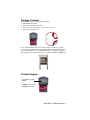
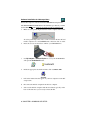
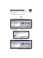
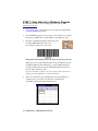
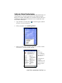
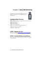
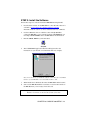
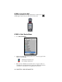
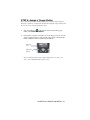
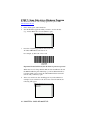
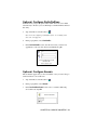
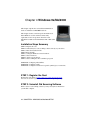
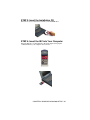
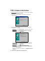
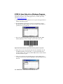
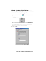
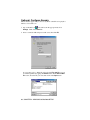
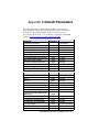
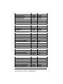
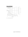
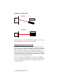
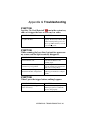
In-Hand Scan Card™ and
In-Hand Scan Card-Xtreme™
CompactFlash Card with
Built-in Bar Code Laser Scanner for:
• Pocket PCs and Pocket PC 2002s
• Handheld PC Pros, HPC 2000s and Pen Tablets
based on Windows CE
• Windows 9x/Me/2000 Notebooks
• Casio BE-300 Cassiopeia Pocket Manager
User’s Guide
How This Manual Is Organized
This User’s Guide contains separate chapters covering the installation and
use of the In-Hand Scan Card (and In-Hand Scan Card-Xtreme) on different
Windows platforms.
Chapter 1, “Introduction,” gives you an overview of the In-Hand Scan
Card package.
Chapter 2, “Windows CE Setup,” tells you how to install the In-Hand
Scan Card on a mobile computer based on Windows CE (v2.11 or greater).
Chapter 3, “Casio BE-300 Setup,” explains how to install the In-Hand
Scan Card on a Casio BE-300 Cassiopeia Pocket Manager.
Chapter 3, “Windows 9x/Me/2000 Setup,” tells you how to install the
In-Hand Scan Card on a notebook computer with Windows 95/98/Me/2000.
Appendix A, “ISC Specifications,” describes the technical specifications
of the In-Hand Scan Card packages.
Appendix B, “Bar Code Label Specifications,” includes technical
specifications for bar code labels regarding background substrate, ink color
and type, voids and specks, definition, contrast, and tolerance.
Appendix C, “Class 1 vs. Class 2 Lasers,” compares and contrasts the two
kinds of lasers.
Appendix D, “Default Parameters,” lists the symbologies and other
parameters that have been set as default for the ISC.
Appendix E, “Decode Zone,” provides a diagram showing the In-Hand
Scan Card’s scanning range.
Appendix F, “PDF417 Bar Codes,” provides basic information about the
PDF417 symbology, how to scan a PDF417 bar code with the ISC-Xtreme,
and how to manage the decoded data.
Appendix G, “Troubleshooting,” helps you correct the most common
problems you may encounter using the In-Hand Scan Card.
Appendix H, “Technical Support,” tells you how to contact Socket’s
technical support department and lists information you should prepare
yourself with before seeking help.
Table of Contents
CHAPTER 1 INTRODUCTION
4
CHAPTER 2 WINDOWS CE SETUP
6
CHAPTER 3 CASIO BE-300 SETUP
18
CHAPTER 4 WINDOWS 9X/ME/2000 SETUP
24
APPENDIX A ISC SPECIFICATIONS
32
APPENDIX B BAR CODE LABEL SPECIFICATIONS
33
APPENDIX C CLASS 1 VS. CLASS 2 LASER SCANNERS
34
APPENDIX D DEFAULT PARAMETERS
37
APPENDIX E DECODE ZONES
40
APPENDIX F PDF417 BAR CODES AND THE ISC-XTREME
42
APPENDIX G TROUBLESHOOTING
45
APPENDIX H TECHNICAL SUPPORT
46
LIMITED WARRANTY
47
COPYRIGHT NOTICE
49
REGULATORY COMPLIANCE
50
Chapter 1 Introduction
Overview
The Socket In-Hand Scan Card (ISC) gives you
the freedom of scanning bar codes anytime
anywhere with a variety of Windows-based
mobile computers. Just pop in the scanner when
you need it, then remove it when you’re done.
Plus, the card’s compact design lets you scan
with only one hand when used with a PDA.
The world’s only bar code laser scanner built into a CompactFlash card, the
ISC is sleekly designed with no cables or batteries. The ISC is available in
two configurations: with a Class 1 laser for normal scanning applications or
with a Class 2 laser for more demanding requirements. Please see Appendix
C for a more detailed explanation of the two types of laser scanners.
The new ISC-Xtreme adds the ability to scan PDF417 2-D bar codes. Please
see Appendix F for more information on PDF417 bar codes.
When combined with a Type I CompactFlash-to-PC Card adapter, the
CompactFlash ISC and ISC-X also work in the PC Card slot of a Pocket
PC, Handheld PC Pro, HPC 2000 or Windows 9x/Me/2000 notebook.
The In-Hand Scan Card packages include SocketScan™ software.
SocketScan’s “keyboard wedge” function sends scanned data to any active
Windows program as if it were manually typed, so you can use the ISC with
virtually any Windows program.
Other features of the In-Hand Scan Card package include:
• Automatic detection of major bar code symbologies, such as Code 39,
Code 93, UPC/EAN, Code 128, Codabar, and MSI Plessey. Additional
symbologies can easily be enabled.
• No clumsy cables or additional batteries.
• Mobility Friendly™ design maximizes your mobile computer’s battery
life.
This User’s Guide shows how to install and use the In-Hand Scan Card and
In-Hand Scan Card-Xtreme. Except where otherwise noted, “In-Hand Scan
Card” also refers to the In-Hand Scan Card-Xtreme.
For software updates or help on advanced configuration, please visit:
www.socketcom.com/support/support_bar.htm
4 | CHAPTER 1: INTRODUCTION
Package Contents
The In-Hand Scan Card (ISC) package includes:
• The In-Hand Scan Card
• The SocketScan Installation CD
• The Socket Quick Start Guide for Bar Code Scanners
• A product registration card
If you purchased the In-Hand Scan Card with PC Card Adapter package,
your package also includes a Type I CompactFlash-to-PC Card adapter that
lets you use the ISC in a PC Card (PCMCIA) slot of a Windows computer.
This adapter can be ordered separately as Socket part number AC4000-978.
Product Diagram
Light Emitting Diode
(LED)
AMBER: Laser activity
GREEN: Good read
CHAPTER 1: INTRODUCTION | 5
Chapter 2 Windows CE Setup
This chapter shows how to install, configure, and use
the In-Hand Scan Card (ISC) on any Windows Powered
Pocket PC (including Pocket PC 2002) or Windows CEbased Handheld PC Pro, HPC 2000 or pen tablet.
This chapter shows Pocket PC 2002 screens. Other
Windows CE devices will have functionally equivalent
screens except where otherwise noted.
Installation Steps Summary
STEP 1: Register the card.
STEP 2: Uninstall any bar code scanning software already on your device.
STEP 3: Install the software.
STEP 4: Insert the ISC into Your Device.
STEP 5: Start SocketScan.
STEP 6: Assign a trigger button.
STEP 7: Start scanning data into a Windows program!
OPTIONAL: Select symbologies.
OPTIONAL: Configure prefix/suffixes.
OPTIONAL: Run Scan Demo application to scan unknown bar codes.
OPTIONAL: Configure sounds.
OPTIONAL: Manually configure specific symbologies or extensions.
STEP 1: Register the Card
Register the card online at www.socketcom.com/product/prodreg.htm
You can also use the registration form included in the product package.
STEP 2: Uninstall Old Scanning Software
Delete any bar code scanning software you may already have installed on
your mobile computer.
6 | CHAPTER 2: WINDOWS CE SETUP
STEP 3: Install the Software
Software Installation for Internet Explorer Users
Follow these steps for software installation BEFORE inserting the ISC.
Internet Explorer must be the default web browser. If Netscape is the
default browser on your host PC, please turn the page for instructions.
1.
Make an active partnership between the mobile computer and a host
PC. Internet Explorer must be the default web browser on the host PC.
An active partnership exists if data can move between the host PC and
mobile computer via a serial/USB/Ethernet connection cable or cradle.
2.
Insert the SocketScan Installation CD into your CD-ROM drive.
3.
Use My Computer or Windows Explorer to access your CD-ROM drive.
In the CD, click on SETUP.HTM.
4.
Follow the SocketScan Setup Center to install the software.
5.
In the File Download screen, select the option that lets you open (or run)
the file from its current location.
IMPORTANT!
YOU MUST OPEN
THE FILE!
DO NOT SAVE!
4.
A Security Warning screen will appear. Click Yes.
5.
Follow the instructions that appear on your screen until setup is done.
6.
Disconnect the mobile computer from the host PC. Soft reset the
mobile computer.
7.
Push the reset button, typically located on the back or side of the unit.
Now you are ready to insert the ISC.
CHAPTER 2: WINDOWS CE SETUP | 7
Software Installation for Netscape Users
Follow these steps for software installation BEFORE inserting the ISC.
The SETUP.HTM file DOES NOT work with Netscape. Instead, you must
use the SETUP.EXE file inside the SocketScan folder for Windows CE.
1.
Make an active partnership between the mobile computer and host PC.
An active partnership exists if data can move between the host PC and
mobile computer via a serial/USB/Ethernet connection cable or cradle.
2.
Insert the SocketScan Installation CD into your CD-ROM drive.
3.
Use My Computer or Windows Explorer to access your CD-ROM drive
and open the SocketScanCE folder.
4.
Inside the appropriate SocketScan folder, click on SETUP.EXE.
5.
Follow the instructions that appear on your host computer screen until
setup is done.
6.
Disconnect the mobile computer from the host computer.
7.
Soft reset the mobile computer. Push the reset button, typically on the
back of the unit. Now you are ready to insert the ISC.
8 | CHAPTER 2: WINDOWS CE SETUP
STEP 4: Insert the ISC into Your Device
Plug directly into
a CompactFlash
I/O slot.
OR
Insert into
an adapter,
then plug
the
combined
unit into a
PC Card
slot.
STEP 5: Start SocketScan
1.
Pocket PCs: Go to Start | Programs | SocketScan.
HPCs: Tap on the SocketScan icon on your desktop.
2.
Whenever SocketScan is running, either of two icons may appear in the
task tray (visible from the Today screen for Pocket PCs).
In-Hand Scan Card detected
No scanning card detected
3.
Make sure the “In-Hand Scan Card detected” icon appears.
If the “no card detected” icon appears instead, you may have an
improperly inserted card. Remove and reinsert the card, pushing it in
all the way.
CHAPTER 2: WINDOWS CE SETUP | 9
STEP 6: Assign a Trigger Button
Follow the appropriate directions for your device and refer to your device’s
user documentation to assign a trigger button for the In-Hand Scan Card
(ISC).
Note: If SocketScan is not running yet, then pressing the assigned
trigger button is a quick way to launch SocketScan. Pressing the
trigger button will fire the laser only when SocketScan is open.
Pocket PC
These instructions are for a Pocket PC or Pocket PC 2002.
1. Go to Start | Settings | Personal | Buttons.
2. From the Button list, select a button to trigger the In-Hand Scan Card.
In the Button assignment field, select SocketScan. When done, tap ok.
10 | CHAPTER 2: WINDOWS CE SETUP
Handheld PC Pro, HPC 2000 or Pen Tablet
These instructions were based on a HP Jornada 720
Handheld PC 2000. The procedure for assigning a trigger key
can vary from device to device. Consult your device’s user
documentation if necessary.
1. Tap Start | Settings | Control Panel | HP hot keys:
2. The HP hot keys Properties screen will appear.
3. Under the Assign to: field, tap on the Browse button to select
SocketScan. Tap OK.
4. After SocketScan appears in the Assign to: field, tap OK.
CHAPTER 2: WINDOWS CE SETUP | 11
STEP 7: Scan Data into a Windows Program
For information about bar code scanning applications, please email
[email protected]
1.
If not already open, start SocketScan. You can press the trigger button
to quickly launch the program.
2.
Start the Windows application you want to receive the data (e.g., Excel,
Notepad, etc.). Make sure a new document or spreadsheet is open.
3.
Press the assigned trigger button and scan the code.
An amber LED indicates the laser is on.
For example, try this Code 39 bar code:
Important! Do not look directly into the beam or point it at a person!
When data is read, a beep should sound, the laser should turn off, and
the LED should turn green, indicating a good read. If the ISC fails to
read data within a few seconds, the amber LED and laser beam will
turn off, and you must try again.
Note: If your mobile computer enters sleep mode when SocketScan is
running, press the ON button to restart SocketScan.
4.
After a successful scan, data should appear in your document. For
example, after you scan the code above into a Pocket Excel
spreadsheet, data should appear in the first cell:
12 | CHAPTER 2: WINDOWS CE SETUP
Optional: Select Symbologies
The applet makes it quick and convenient to modify which symbologies you
want SocketScan to recognize. This feature is only available for the InHand Scan Card (ISC) and In-Hand Scan Card-Xtreme (ISC-X) when used
with Windows CE. By default, SocketScan is set to recognize nine of the
most common symbologies.
1.
Tap on the ISC icon in the task tray
the Today screen for Pocket PCs).
to launch the applet (visible in
2.
In the pop-up menu, select Symbology Selector...
3.
In the screen that appears, check the symbologies you wish to enable.
Uncheck those you wish to disable. Tap ok.
Note:
1. You may
select PDF 417
only if using the
ISC-Xtreme.
2. Enabling all
possible
symbologies will
make the decode
process slightly
longer.
CHAPTER 2: WINDOWS CE SETUP | 13
Optional: Configure Prefix/Suffixes
The SocketScan applet lets you specify prefix and/or suffix characters to be
added automatically to the data you scan. This helps to further eliminate
manual data entry.
1.
Tap on the ISC icon in the task tray
the Today screen for Pocket PCs).
to launch the applet (visible in
Note: You can configure prefix/suffixes if the “no scanning card
detected” icon appears.
2.
In the pop-up menu, select Prefix/Suffix...
3.
In the screen that appears, enter the characters you want to be appended
to each scan (128 character maximum). Tap ok.
14 | CHAPTER 2: WINDOWS CE SETUP
Optional: Run Scan Demo
Scan Demo makes it easy to determine the symbology, number of
characters, and decoded data (in either ASCII or Hex) of any bar code you
scan. This is especially useful if you encounter a bar code that SocketScan
will not decode. This SocketScan feature is only available for Windows CE.
1.
Tap on the ISC icon in the task tray
the Today screen for Pocket PCs).
2.
In the pop-up menu, select Scan Demo. This will close SocketScan and
open Scan Demo as a separate application.
3.
The Scan Demo screen will appear. If desired, use the check boxes at
the bottom of the screen to modify the test.
to launch the applet (visible in
Enable all symbologies: By default, this option is checked. Different
symbologies can sometimes interpret the same bar code differently, so
you may want to uncheck this option.
Display as hex data: Check this box to view scanned data in
hexidecimal format. Otherwise, data will appear as ASCII.
4.
Scan the bar code.
5.
Scan Demo will report properties of the bar code you scan.
CHAPTER 2: WINDOWS CE SETUP | 15
Optional: Configure Sounds
The SocketScan applet lets you choose any WAV sound file to be played to
indicate a successful scan.
1.
Tap on the ISC icon in the task tray
the Today screen for Pocket PCs).
2.
In the pop-up menu, select Sounds...
3.
In the screen that appears, select a sound for indicating successful
scans. Tap ok.
to launch the applet (visible in
Browse box
To you want to play a .WAV file, after selecting Play .wav file, you can
search through files by tapping the browse box. In the Open screen, tap
on the file you want:
Note: For Pocket
PCs and Pocket
PC 2002s, you can
only select a WAV
file from the My
Documents folder.
If needed, copy the
file you need to this
folder.
16 | CHAPTER 2: WINDOWS CE SETUP
Optional: Configure Special Symbologies
In addition to the eighteen symbologies supported by the Symbology
Selector, you can also manually configure the ISC to accept or ignore
specialized bar code symbologies and extensions.
See Appendix D, “Default Parameters,” to see parameter numbers and
default settings of each symbology. Also please refer to the Symbol 923
Programming Guide Chapter 5 for In-Hand Scan, available online in Adobe
Acrobat PDF format at: www.socketcom.com/support/support_bar.htm
CHAPTER 2: WINDOWS CE SETUP | 17
Chapter 3 Casio BE-300 Setup
This chapter shows how to install, configure, and use the
In-Hand Scan Card (ISC) on a Casio BE-300 Cassiopeia
Pocket Manager.
Installation Steps Summary
STEP 1: Register the card.
STEP 2: Uninstall any bar code scanning software already on your device.
STEP 3: Install the software.
STEP 4: Insert the ISC.
STEP 5: Start SocketScan.
STEP 6: Assign a trigger button.
STEP 7: Start scanning data into a Windows program!
OPTIONAL: Configure prefix/suffixes
OPTIONAL: Configure sounds.
STEP 1: Register the Card
Register the card online at www.socketcom.com/product/prodreg.htm
You can also use the registration form included in the product package.
STEP 2: Uninstall Old Scanning Software
Delete any bar code scanning software you may already have installed on
your Casio BE-300.
18 | CHAPTER 3: CASIO BE-300 SETUP
STEP 3: Install the Software
Follow these steps for software installation BEFORE inserting the ISC:
1.
Download the software for the BE-300 onto a host PC. The software is
available at: www.socketcom.com/support/support_bar.htm
DO NOT install the software from the installation CD onto a BE-300!
2.
Use the USB/serial cable or cradle that came with the BE-300 to
connect the BE-300 to a host computer. Perform a PC Connect. If you
need help with PC Connect, refer to the BE-300 user documentation.
3.
Run the SETUP.EXE that you downloaded.
4.
The CASSIOPEIA Application Installer will begin. Follow the
instructions on your host PC screen until installation is complete.
Note: You can choose to install the software either directly to the Main
memory of your BE-300 or to a removable memory card.
5.
When installation is finished, disconnect the BE-300 from the host PC.
6.
Soft reset the BE-300. Push the reset button, located on the left side of
the BE-300. Now you are ready to insert the card.
Important! Soft reset the BE-300 after software installation!
Push the reset button, located on the left side of the unit!
CHAPTER 3: CASIO BE-300 SETUP | 19
STEP 4: Insert the ISC
Plug the ISC into the device’s CompactFlash I/O slot. The CF icon
should appear in the status bar at the bottom of the screen.
STEP 5: Start SocketScan
1.
Go to Main | SocketScan.
2.
Whenever SocketScan is running, either of two icons may appear in the
status bar of the BE-300.
In-Hand Scan Card detected
No scanning card detected
3.
Make sure the “In-Hand Scan Card detected” icon appears. If the “no
card detected” icon appears instead, you may have improperly inserted
card. Remove and reinsert the card, pushing it in all the way.
20 | CHAPTER 3: CASIO BE-300 SETUP
STEP 6: Assign a Trigger Button
Note: If SocketScan is not running yet, then pressing the assigned trigger
button is a quick way to launch SocketScan. Pressing the trigger button will
fire the laser only when SocketScan is open.
1.
Tap on the ISC icon
at the bottom of the screen. In the pop-up
menu, select Enable Scan Buttons.
2.
Press the key or button you wish to use as the trigger. You can use any
of the seven shortcut keys at the bottom of the screen or the Launcher
button (with the rocket icon). The laser should fire.
Shortcut
keys
Launcher
button
Note: You must assign a trigger button again after every time your
device enters Suspend mode or powers off.
CHAPTER 3: CASIO BE-300 SETUP | 21
STEP 7: Scan Data into a Windows Program
For information about bar code scanning applications, please email
[email protected]
1.
If not already open, start SocketScan.
2.
Start the Windows application that you want to receive the data
(e.g., Notes). Make sure a new document is open.
3.
Press the assigned trigger button and scan the code.
An amber LED indicates the laser is on.
For example, try this Code 39 bar code:
Important! Do not look directly into the beam or point it at a person!
When data is read, a beep should sound, the laser should turn off, and
the LED should turn green, indicating a good read. If the ISC fails to
read data within a few seconds, the amber LED and laser beam will
turn off, and you must try again.
4.
After a successful scan, data should appear in your document. For
example, if you scan the bar code above into a Notes document, the
following will appear:
22 | CHAPTER 3: CASIO BE-300 SETUP
Optional: Configure Prefix/Suffixes
SocketScan lets you specify prefix and/or suffix characters to be added
automatically to the data you scan. This helps to further eliminate manual
data entry.
1.
Tap on the ISC icon in the task tray
.
Note: You can configure prefix/suffixes if the “no scanning card
detected” icon appears.
2.
In the pop-up menu, select Prefix/Suffix...
3.
In the Set Prefix/Suffix screen, enter the characters you want to be
appended to each scan (128 character maximum). Tap ok.
Optional: Configure Sounds
The SocketScan applet lets you choose whether or not you want a beep to
sound to indicate a successful scan.
1.
Tap on the ISC icon in the task tray
2.
In the pop-up menu, select Sounds...
3.
In the Set Good-Read Sound screen, select a sound for indicating
successful scans. Tap OK.
.
CHAPTER 3: CASIO BE-300 SETUP | 23
Chapter 4 Windows 9x/Me/2000
This chapter explains how to install the In-Hand Scan
Card on a Windows 9x/Me/2000 notebook.
This chapter features screen images from Windows 98.
Other Windows versions will have functionally
equivalent screens except where otherwise noted.
The ISC does NOT work with Windows XP or NT at this
time.
Installation Steps Summary
STEP 1: Register the card.
STEP 2: Uninstall any bar code scanning software already on your device.
STEP 3: Insert the installation CD.
STEP 4: Insert the ISC.
STEP 5: Configure Windows for new hardware.
STEP 5: Start SocketScan.
STEP 6: Assign a trigger button.
STEP 7: Start scanning data into a Windows program!
OPTIONAL: Configure prefix/suffixes
OPTIONAL: Configure sounds.
OPTIONAL: Configure SocketScan for specific symbologies or extensions.
STEP 1: Register the Card
Register the card online at www.socketcom.com/product/prodreg.htm
You can also use the registration form included in the product package.
STEP 2: Uninstall Old Scanning Software
Delete any bar code scanning software you may already have installed on
your mobile computer.
24 | CHAPTER 4: WINDOWS 9x/Me/2000 SETUP
STEP 3: Insert the Installation CD
Insert the SocketScan Installation CD into your CD-ROM drive.
STEP 4: Insert the ISC into Your Computer
Insert the ISC into a CompactFlash-to-PC Card adapter, then plug the
combined unit into your computer’s PC Card slot.
CHAPTER 4: WINDOWS 9x/Me/2000 SETUP | 25
STEP 5: Configure for New Hardware
1. Make sure the installation CD is still inside your computer.
2. Windows 2000: After you insert the ISC, a screen may appear reporting
Digital Signature Not Found. Click Yes.
3. The first time you insert the ISC, a new hardware or device driver
wizard will appear.
4. Follow the wizard to install the ISC drivers, making the appropriate
selection below as prompted:
a. Windows 95 — Select Other Locations... and specify your CD drive.
b. Windows 98 — Select Search for the best driver for your device.
In the next screen, select CD-ROM drive.
c. Windows 2000 — Select Search for a suitable driver for my device.
In the next screen, select CD-ROM drive.
d. Windows Me — Select Specify the location of the driver.
In the next screen, select Search for the best driver for your device,
and check Removable Media.
Important! For Windows Me, DO NOT select Automatic search for a
new driver!
26 | CHAPTER 4: WINDOWS 9x/Me/2000 SETUP
STEP 6: Start SocketScan
Go to Start | Programs | SocketScan.
Whenever SocketScan is running and the ISC is inserted, the ISC icon
should appear in the your device’s status bar.
The “no card detected” icon
may denote an improperly inserted card.
STEP 7: Assign a Trigger Button
Note: If SocketScan is not running yet, then pressing the assigned trigger
button is a quick way to launch SocketScan. Pressing the trigger button will
fire the laser only when SocketScan is open.
Follow these steps and refer to your Windows documentation to assign a
trigger button:
1. Right-click the ISC icon
on your Windows task tray.
2. In the pop-up menu that appears, click Settings…
3. In the next screen, select a function key for the trigger button. Click OK.
Important!
Be careful not
to pick a key
used by
another
program!
CHAPTER 4: WINDOWS 9x/Me/2000 SETUP | 27
STEP 8: Scan Data into a Windows Program
Follow these steps to use the ISC to scan data into a Windows program. For
information about bar code scanning applications (available separately),
email [email protected]
1. If not already open, start SocketScan. You can press the trigger button to
quickly launch the program.
2. Start the Windows application you want to receive the data, such as
Notepad, Word or Excel. Make sure a new document or spreadsheet is
open that you can scan data into.
3. Press the assigned trigger button and scan the code. An amber LED
indicates the laser is on. For example, try this Code 39 bar code:
Important! Do not look directly into the beam or point it at a person!
4. When data is read, a beep should sound, the laser should turn off, and
the LED should turn green, indicating a good read. If the ISC fails to
read data within a few seconds, the amber LED and laser beam will turn
off, and you must try again.
5. After a successful scan, data should appear in your document. If you
scan the code above into an Excel spreadsheet, data should appear in the
first cell:
28 | CHAPTER 4: WINDOWS 9x/Me/2000 SETUP
Optional: Configure Prefix/Suffixes
The SocketScan applet lets you specify prefix and suffix characters or
functions to be added automatically to the data that you scan. This makes it
easy to use the ISC with existing Windows applications.
1. Right-click on the SocketScan icon
your screen.
in the task bar at the bottom of
2. In the pop-up menu, select Settings…
3.
Start the applet. In SocketScan Settings, click on the Prefix/Suffix tab.
4.
In the Prefix and Suffix fields, enter the characters you want to be
appended to each scan (128 character maximum).
When done, click OK.
CHAPTER 4: WINDOWS 9x/Me/2000 SETUP | 29
Optional: Configure Sounds
The SocketScan applet lets you choose any WAV sound file to be played to
indicate a successful scan.
1. Tap on the ISC icon
in the task bar. In the pop-up menu, select
Settings. Click on the Sound tab.
2. Select a sound for indicating successful scans, then click OK.
To you want to play a .WAV file, after selecting Play .wav file, you can
search through files by tapping the Browse button. In the Select a WAV
file screen, select the file you want, then click on the Open button:
30 | CHAPTER 4: WINDOWS 9x/Me/2000 SETUP
Optional: Configure Symbologies
You can manually configure the ISC to accept or ignore certain bar code
symbologies and extensions. Check Appendix B, “Default Parameters,” to
see if the ISC is already configured for the symbology you need.
Default symbologies include Code 39, Code 128, UPC/EAN, MSI Plessey,
Code 93 and Codabar.
To reconfigure your ISC for different symbologies, please refer to Symbol
923 Programming Guide Chapter 5 for In-Hand Scan, available in Adobe
Acrobat PDF format at: www.socketcom.com/support/support_bar.htm
CHAPTER 4: WINDOWS 9x/Me/2000 SETUP | 31
Appendix A ISC Specifications
Physical Characteristics:
CompactFlash CF Card Size:
1.77 x 1.68 x 0.13 in (45 x 42.8 x 3.3 mm)
Laser Scanner Size:
1.97 x 1.45 x 0.83 in (36.8 x 50 x 21 mm)
Total Weight: approx. 1.8 oz (51.5 g)
ISC Power Consumption with Class 1 or Class 2 Laser (3.3V supply):
Idle: 4 mA (13 mW)
Scanning: 75 mA (248 mW)
(Also operates on 5V supply)
ISC-X Power Consumption (3.3V supply):
Idle: 13 mA (43 mW)
Scanning: 288 mA (950 mW)
(Also operates on 5V supply)
Operating System Support:
Windows CE v2.11 for Handheld PC Pro and pen tablet
Windows CE v3.0 for Pocket PC, Pocket PC 2002, HPC 2000
Windows CE for Casio BE-300
Windows 95, 98, Me, and 2000
Compatibility: Windows or MS-DOS COM port
Bar Code Symbologies Automatically Detected:
Code 39, UPC/EAN, Code 128, Code 93, Codabar, and MSI Plessey.
Other symbologies can be easily enabled
Laser Scanner Performance:
Scan Repetition Rate: 39 (± 3) scans/sec (bidirectional)
Decode Distances:
2.2 to 60.0 in (dependent on symbol density, symbology, W-N Ratio,
label media, and scan angle)
Scan Angle: 53° typical
Interface Standards:
CompactFlash CF, Type I Extended
PC Card (with CompactFlash-to-PC Card adapter)
Certification: FCC: Part 15, Class B, CE: EN55024:1998, C-TICK s.182
Software:
Universal Installer, configuration utility and virtual keyboard wedge for
Windows
32 | APPENDIX A: ISC SPECIFICATIONS
Appendix B Bar Code Label
Specifications
All bar code symbols/labels should satisfy the appropriate AIM Uniform
Symbology Specification.
Background Substrate:
The bar code symbol should be printed on material (media) that is reflective
and has a matte (not glossy) finish. A background diffuse reflectance of at
least 70% to 80% is desirable for optimum contrast. Retro-reflective media
should be used to obtain decode distances greater than 36 inches.
Ink Color and Type:
The inked bars should not exceed 25% reflectance at the wavelength that is
being used for reading, whether printed with black ink or colored ink. The
reflectance value should not vary more than 5% within the same character.
Voids and Specks:
The code should be printed clearly, free of voids, specks, blemishes and
lines that could “fool” the scanner. Specks or blemishes in the white
spaces, or false or missing bar sections could be interpreted by the reading
equipment as part of the code. Generally, the width of such flaws is more
serious than the height. Code symbols/ labels should be rejected if these
defects are present.
Definition:
The bars in the bar code symbol should be well defined. Their edges should
not be rough or fuzzy, so that the bars and spaces have the proper widths
intended for the bar code symbology used.
Contrast:
Background reflectance (that of the substrate on which the codes are
printed) should always provide a good contrast relative to the ink
reflectance (that of the code bars). The difference between the two should
be at least 37.5% at the wavelength used for reading.
Tolerance:
The ratio of the widths of bars and spaces in a bar code symbol must
conform to the appropriate AIM bar code specifications and can cause
problems if not correct throughout the bar code. Problems can occur when
bar edges are smeared or rough, or when they exhibit voids.
APPENDIX B: BAR CODE LABEL SPECIFICATIONS | 33
Appendix C Class 1 vs. Class 2
Laser Scanners
This is a paper on bar code laser scanners that Jack Brandon, Product
Marketing Manager of Scanner Products for Socket Communications,
published in September 2001. You can download a copy of this paper at:
www.socketcom.com/about/techbrief.htm
Introduction
Socket now offers the popular In-Hand Scan Card (ISC) with either a
Class 1 or Class 2 laser. This document describes the differences between
the two devices and the appropriate applications for each.
The primary difference is the power output of the laser. The Class 1 laser
has a nominal power output of 0.5 milliwatts, while the output of the Class 2
laser is 1.2 milliwatts. This difference impacts the scanning performance of
the device in three ways:
1.
Distance — For scanning distances of up to 10 inches, there is very
little difference in the ability of either the Class 1 or the Class 2 laser to
scan a given bar code. Beyond 10 inches, the Class 2 laser will scan a
standard, high quality bar code about 20% - 25% farther than the Class
1 laser.
Scanning a standard bar code of any size at a distance greater than 25
inches becomes difficult with the Class 1 laser, while the Class 2 laser
will easily scan very large bar codes at 60 inches and beyond. There are
a many variables involved in determining the distance at which a bar
code can be scanned, including:
a.
The size of the bar code — The width of the narrowest bar in
thousandths of an inch (or ‘mils’) is referred to as the “X
dimension” or “size” of a bar code. Standard retail UPC or EAN
bar codes are 10 mils (0.010 inches). Larger bar codes, such as
warehouse location bar codes, can be 200 mils or larger. The
larger a bar code, the greater the distance from which it can be
scanned.
Please refer to the Decode Zone charts in Appendix A for more
detailed information on the relationship between the size of a bar
code and the distance at which it can be scanned.
34 | APPENDIX C: CLASS 1 VS. CLASS 2 SCANNERS
b.
The label media — The media is the material a bar code is printed
on. This is usually some type of paper but can also be a plastic or
even metallic material. Because the reading mechanism in a bar
code scanner is based on contrast, the whiter and more reflecting a
media is, the farther away it can be scanned. Retro-reflective
media (like a stop sign) is used for scanning very large bar code
labels at distances of 20 feet and more.
c.
The bar code symbology — There are many different bar code
symbologies (or ‘languages’), such as UPC, EAN, Code 39, Code
128, Code 93 and more. Some symbologies are easier to decode
than others and can, therefore, be scanned at greater distances.
2.
Packaging or covering materials — The Class 2 laser can more
effectively scan through difficult packaging materials such as Mylar
(used for electronic components) or thick plastic or glass such as
automobile windshields.
3.
Ambient light — The Class 2 laser can more effectively scan in high
ambient light conditions such as high intensity lighting or even daylight
(indirect sunlight). Scanning bar codes in direct sunlight is extremely
difficult because sunlight contains enough energy in the red spectrum
used by the laser to ‘blind’ the scanner’s decode system.
The second difference between the Class 1 and Class 2 lasers in the Socket
In-Hand Scan Card is the wavelength frequency of the laser beam. The
Class 1 laser has a 670 nanometer (nm) beam common in most laser bar
code scanners, while the Class 2 features a 650nm beam. There is no
difference in the scanning capability of the two frequencies, but the 650nm
beam is more visible to the human eye, making it appear brighter than the
Class 1 laser.
The user must see the oscillating laser beam in order to aim it effectively at
the bar code to be scanned. The Class 2, 650nm laser is easier to see and
aim than the Class 1 laser, especially when scanning at greater distances,
through difficult materials or in high ambient light.
A third difference between the Class 1 and Class 2 lasers is the current
demand during scanning. At 3.3 Volt power (standard for CompactFlash
card slots) the Class 1 laser draws about 67 milliamps (mA) and the Class 2
laser draws about 75mA. Both lasers draw about 3 - 4mA when idle.
Therefore, for a given level of scanning activity, using the Class 1 laser
should result in a slightly longer battery life.
A final consideration in the selection of either a Class 1 or Class 2 laser is
safety. Staring directly into any laser beam for an extended period of time
will cause damage to the eyes of humans and animals. The normal use of a
bar code scanner is inherently very safe because (a) the laser is typically
APPENDIX C: CLASS 1 VS. CLASS 2 SCANNERS | 35
aimed away from the person using the scanner, and (b) the beam oscillates
39 times per second over a 53 degree arc, making it impossible to stare into
the beam. Additionally, using the lower powered Class 1 laser makes it even
less likely that eye damage will occur. There are certain organizations in
Europe, in fact, that require a Class 1 laser in bar code scanners to meet
more stringent safety standards. The Socket In-Hand Scan Card with Class
1 laser meets these European safety standards. Please refer to Appendix B
for more detailed safety information.
Conclusion
The Class 1 laser is suitable for most applications with expected scanning
distances of less than 20 inches and normal ambient light conditions. The
Class 1 laser may be required by certain European organizations to meet
more stringent safety standards.
When an application is likely to require more demanding scanning
capabilities, the Class 2 laser provides the assurance of maximum scanning
performance.
Note: People who use portable computers to gather and manage data at the
point of activity are typically very quick to learn how to use a laser bar code
scanner and realize the resulting gains in productivity. They are easily
discouraged, however, if time and effort are required to obtain a successful
scan – thus the decline in popularity of the much less expensive bar code
contact wands seen at most retail checkout counters during the 1980’s. The
higher cost of the Class 2 version of the In-Hand Scan Card is easily
justified if the application requires higher scanning performance.
36 | APPENDIX C: CLASS 1 VS. CLASS 2 SCANNERS
Appendix D Default Parameters
Check the table below to identify default parameters for the ISC. To
program different settings, please use the Symbology Selector feature in
SocketScan or the parameter number and refer to the Symbol 923
Programming Guide Chapter 5 for In-Hand Scan in Adobe Acrobat PDF
format at: www.socketcom.com/support/support_bar.htm
Parameter
Parameter #
Set Default Parameter
Beeper Tone
0x91
Laser On Time
0x88
Aim Duration
0xED
Power Mode
0x80
Trigger Mode
0x8A
Time-out Between Same Symbol
0x89
Beep After Good Decode
0x38
Transmit "No Read" Message
0x5E
Parameter Scanning
0xEC
Linear Code Type Security Levels
0x4E
Bi-directional Redundancy
0x43
Default
All Defaults
Medium Frequency
3.0 sec
0.0 sec
Low Power
Level
1.0 sec
Enable
Disable
Enable
1
Disable
UPC/EAN
Parameter #
UPC-A
0x01
UPC-E
0x02
UPC-E1
0x0C
EAN-8
0x04
EAN-13
0x03
Bookland EAN
0x53
Decode UPC/EAN Supplementals
0x10
Default
Enable
Enable
Disable
Enable
Enable
Disable
Ignore
Decode UPC/EAN Supplemental
Redundancy
Transmit UPC-A Check Digit
Transmit UPC-E Check Digit
Transmit UPC-E1 Check Digit
UPC-A Preamble
UPC-E Preamble
UPC-E1 Preamble
7
Enable
Enable
Enable
System Character
System Character
System Character
0x50
0x28
0x29
0x2A
0x22
0x23
0x24
APPENDIX D: DEFAULT PARAMETERS | 37
UPC/EAN
Convert UPC-E to A
Convert UPC-E1 to A
EAN-8 Zero Extend
Convert EAN-8 to EAN-13 Type
UPC/EAN Security Level
UPC/EAN Coupon Code
Parameter #
0x25
0x26
0x27
0xE0
0x4D
0x55
Default
Disable
Disable
Disable
Type is EAN-13
0
Disable
Code 128
USS-128
UCC/EAN-128
ISBT 128
Parameter #
0x08
0x0E
0x54
Default
Enable
Enable
Enable
Code 39
Code 39
Trioptic Code 39
Convert Code 39 to Code 32
Code 32 Prefix
Set Length(s) for Code 39
Parameter #
0x00
0x0D
0x56
0xE7
0x12
0x13
0x30
0x2B
0x11
Default
Enable
Disable
Disable
Disable
2-55
2-55
Disable
Disable
Disable
Code 93
Code 93
Set Length(s) for Code 93
Parameter #
0x09
0x1A
0x1B
Default
Disable
4-55
4-55
Interleaved 2 of 5
Interleaved 2 of 5
Set Length(s) for I 2 of 5
Parameter #
0x06
0x16
0x17
0x31
0x2C
0x52
Default
Enable
14
14
Disable
Disable
Disable
Code 39 Check Digit Verification
Transmit Code 39 Check Digit
Code 39 Full ASCII Conversion
I 2 of 5 Check Digit Verification
Transmit I 2 of 5 Check Digit
Convert I 2 of 5 to EAN 13
38 | APPENDIX D: DEFAULT PARAMETERS
Discrete 2 of 5
Discrete 2 of 5
Set Length(s) for D 2 of 5
Parameter #
0x05
0x14
0x15
Default
Disable
12
12
Codabar
Codabar
Set Lengths for Codabar
Parameter #
0x07
0x18
0x19
0x36
0x37
Default
Disable
5-55
5-55
Disable
Disable
Parameter #
0x0B
0x1E
0x1F
MSI Plessey Check Digits
0x32
Transmit MSI Plessey Check Digit
0x2E
Default
Disable
6-55
6-55
One
Disable
MSI Plessey Check Digit
Algorithm
Mod 10/Mod 10
CLSI Editing
NOTIS Editing
MSI Plessey
MSI Plessey
Set Length(s) for MSI Plessey
0x33
APPENDIX D: DEFAULT PARAMETERS | 39
Appendix E Decode Zones
The decode zones for the Class 1 and Class 2 lasers in the In-Hand Scan
Card are shown below. The minimum element width (“X Dimension” or bar
code “size”) is the width in thousandths of an inch (mils) of the narrowest
element (bar or space) in the symbol. The figures shown are the typical
scanning distances for selected bar code sizes. The maximum usable length
of a bar code symbol (Width of Field) at any given range is also shown
below.
Class 1 Laser Decode Zone
40 | APPENDIX E: DECODE ZONES
Class 2 Laser Decode Zone
Source: Symbol Technologies, Inc.
Appendix E: DECODE ZONES | 41
Appendix F PDF417 Bar Codes
and the ISC-Xtreme
About PDF417
Imagine a database that's totally portable - freed from the computer to go
anywhere and yet be accessed immediately at any time. Or a paper-based
communication medium that makes documents, labels and cards "live" with
machine-readable information, including text, graphics, biometrics or other
data. And imagine capturing this information quickly, easily and
inexpensively. There's a technology that offers all this – it’s PDF417.
PDF stands for "Portable Data File". A single PDF417 symbol can
represent up to 1500 bytes of machine-readable data in a label the size of a
small business card. And, unlike traditional one-dimensional bar codes that
depend on real-time links to a larger database, a PDF417 symbol is the
database.
PDF417 answers the need to capture, store and transfer large amounts of
data inexpensively. It can exchange complete data files (such as text,
numerics or binary) and encode graphics, fingerprints, shipping manifests,
electronic data interchange (EDI) messages, equipment calibration
instructions and much more. It provides a powerful communications
capability - without the need to access an external database. And, for
virtually no incremental cost, you can add a PDF symbol to the documents
and labels you are already printing.
Printing PDF417 Bar Codes
PDF417 printing solutions are compatible with all the same printers used to
print 1-D bar codes, including laser, thermal direct, thermal transfer, ink jet
and others. You can print on a wide variety of materials-paper, cards,
labels, plastics, metals and others. You can even fax PDF417 symbols.
Most bar code printing software packages support the printing of PDF417
bar codes.
Scanning PDF417 Bar Codes with the ISC-Xtreme
In order to decode a PDF417 bar code with the Socket In-Hand Scan CardXtreme, the laser must be maneuvered to cover the entire symbol. When
triggered, the ISC-X laser beam sweeps horizontally back and forth 200
times per second, forming a solid bright red line. The user must slowly and
smoothly sweep the laser beam line vertically across the symbol. This
sweeping motion can be either upward or downward, but the beam line
must be parallel with the bottom (or top) of the symbol – it cannot be
42 | PDF417 AND THE ISC-X
skewed or angled. The ISC-X should be held at a distance such that the
horizontal beam line extends past the sides of the symbol. For best results,
the scanner should also be held at an angle of at least 15 degrees from
perpendicular to the surface of the bar code label, as the reflected light from
the scanner can blind the reading mechanism.
Please see the following examples:
Example 1: Vertical sweep
CORRECT
INCORRECT
INCORRECT
The sweeping motion can be either upward or downward, but the beam line
must be parallel with the bottom (or top) of the symbol – it cannot be
skewed or angled. The ISC-X should be held at a distance such that the
horizontal beam line extends past the sides of the symbol.
APPENDIX F: PDF417 AND THE ISC-X | 43
Example 2: Scanning Angle
CORRECT
Pocket PC
Bar
Code
label
INCORRECT
Pocket PC
Bar
Code
Label
For best results, the scanner should be held at an angle of at least 15 degrees
from perpendicular to the surface of the bar code label.
Managing Data from a PDF417 Bar Code
PDF417 bar codes are almost always associated with a specific software
application and the standard SocketScan keyboard emulation is typically of
little use in a PDF417 application. The PDF417 symbol is created with data
that is formatted to match the format of the application. Application
developers wishing to use PDF417 technology and the Socket In-Hand Scan
Card-Xtreme should use the SocketScan Software Developer’s Kit (SDK)
to bypass keyboard emulation and manage the decoded serial data coming
from the CompactFlash communications port.
For more information about the SDK and to download the User Manual,
visit: www.socketcom.com/product/bar_scan_sdk.htm. To obtain the SDK,
complete and submit the Developer’s Survey found on this webpage and
you will be contacted.
44 | PDF417 AND THE ISC-X
Appendix G Troubleshooting
SYMPTOM:
I get the “No Card Detected” icon in the system tray
and can’t trigger the laser or scan any bar codes.
POSSIBLE REASON
Your mobile computer does not
recognize the ISC.
SOLUTION
Make sure the ISC is inserted
properly. If necessary, remove and
reinsert. If using battery power, be
sure to tap Yes if asked if you want
to use battery power.
SYMPTOM:
While scanning, the laser fires, but no data appears on
my screen, and the light eventually disappears.
POSSIBLE REASON
The laser beam is too close or too
far from the bar code.
The bar code is incorrectly
formatted or poorly printed.
The bar code symbology may be
disabled in the ISC configuration.
SOLUTION
Practice so you get accustomed the
most effective distance and
scanning angle.
Try scanning a bar code that is
correctly formatted or printed well,
such as on a retail package.
Use Scan Demo to determine the
symbology. If needed, reconfigure
the ISC.
SYMPTOM:
When I press the trigger button, nothing happens.
POSSIBLE REASON
You programmed the trigger
button incorrectly.
SOLUTION
Test the button by assigning a
different program to it and make
sure it works properly.
APPENDIX G: TROUBLESHOOTING | 45
Appendix H Technical Support
If you have a technical problem while installing or using the In-Hand Scan
Card, please refer to Appendix G, “Troubleshooting.” You are also
welcome to visit Socket’s online users’ forum at www.socketforum.com
Otherwise feel free to contact Socket’s technical support department,
prepared with the following information:
• The part number (including revision number) and serial number of your
In-Hand Scan Card (please see diagram below)
• The manufacturer, model number, and Windows version of your mobile
computer
• If applicable, the Windows version of your host computer
• How you know your In-Hand Scan Card is not working properly and
what you did to try to correct the problem
You can contact Socket the following ways:
• Visit
www.socketcom.com
• Email
[email protected]
• Phone
510-744-2720
• Fax
510-744-2727
Please refrain from disassembling the CompactFlash Card. Disassembly of
this device will void the product warranty.
46 | APPENDIX H: TECHNICAL SUPPORT
Limited Warranty
Socket Communications Incorporated (Socket) warrants this product against defects
in material and workmanship, under normal use and service, for the following
periods from the date of purchase:
Plug-in card: 2 years
Incompatibility is not a defect covered by Socket’s warranty. During the warranty
period, Socket will, at its option, repair or replace the defective product at no charge
when furnished with proof of retail purchase, provided that you deliver the product
to Socket or to an authorized Socket Service Center.
The returned product must be accompanied by a return material authorization
(RMA) number issued by Socket or by Socket's Authorized Service Center. If you
ship the product, you must use the original container or equivalent and you must pay
the shipping charges to Socket. Socket will pay shipping charges back to any
location in the contiguous United States. This warranty applies only to the original
retail purchaser and is not transferable.
Socket may, at its option, replace or repair the product with new or reconditioned
parts and the returned product becomes Socket's property. Socket warrants the
repaired or replaced products to be free from defects in material or workmanship for
ninety (90) days after the return shipping date, or for the duration of the original
warranty period, whichever is greater.
This warranty does not cover the replacement of products damaged by abuse,
accident, misuse or misapplication, nor as a result of service or modification other
than by Socket.
SOCKET IS NOT RESPONSIBLE FOR INCIDENTAL OR CONSEQUENTIAL
DAMAGES RESULTING FROM BREACH OF ANY EXPRESS OR IMPLIED
WARRANTY, INCLUDING DAMAGE TO PROPERTY AND, TO THE EXTENT
PERMITTED BY LAW, DAMAGES FOR PERSONAL INJURY. THIS
WARRANTY IS IN LIEU OF ALL OTHER WARRANTIES INCLUDING
IMPLIED WARRANTIES OF MERCHANTABILITY AND FITNESS FOR A
PARTICULAR PURPOSE.
Some states do not allow limitation of implied warranties, or the exclusion or
limitation of incidental or consequential damages, so that the above limitations or
exclusions may not apply to you. This warranty gives you specific legal rights and
you may also have other rights which vary from state to state.
This product may contain fully tested, recycled parts, warranted as if new.
For warranty information, phone (510) 744-2700.
47
Limited Software Warranty
LIMITED WARRANTY. SOCKET warrants that the original disk or CD ROM is
free from defects for 90 days from the date of delivery of the SOFTWARE.
CUSTOMER REMEDIES. SOCKET’S entire liability and your exclusive remedy
shall be, at SOCKET’S option, either (a) return of the price paid or (b) replacement
of the SOFTWARE which does not meet SOCKET’S Limited Warranty and which
is returned to SOCKET with a copy of your receipt. Any replacement SOFTWARE
will be warranted for the remainder of the original warranty period or 30 days,
whichever is longer. THESE REMEDIES ARE NOT AVAILABLE OUTSIDE OF
THE UNITED STATES OF AMERICA.
NO OTHER WARRANTIES. SOCKET disclaims all other warranties, either
express or implied, including but not limited to implied warranties of
merchantability and fitness for a particular purpose, with respect to the SOFTWARE
and the accompanying written materials. This limited warranty gives you specific
legal rights. You may have others which vary from state to state.
NO LIABILITY FOR CONSEQUENTIAL DAMAGES. In no event shall SOCKET
or its suppliers be liable for any damages whatsoever (including, without limitation,
damages for loss of business profits, business interruption, loss of business
information, or other pecuniary loss) arising out of the use of or inability to use the
SOFTWARE, even if SOCKET has been advised of the possibility of such damages.
Because some states do not allow the exclusion or limitation of liability for
consequential or incidental damages, the above limitation may not apply to you.
EXPORT LAW ASSURANCES. You may not use or otherwise export or reexport
the SOFTWARE except as authorized by United States law and laws of the
jurisdiction in which the SOFTWARE was obtained. In particular, but without
limitation, none of the SOFTWARE may be used or otherwise exported or
reexported (a) into (or to a national or resident of) a United States embargoed
country or (b) to anyone on the U.S. Treasury Department’s list of Specially
Designated Nationals or the U.S. Department of Commerce’s Table of Denial
Orders. By using the SOFTWARE, you represent and warrant that you are not
located in, under control of, or a national or resident of any such country or on any
such list.
GOVERNMENT END USERS. If the SOFTWARE is supplied to the U. S.
Government, the SOFTWARE is classified as “restricted computer software” as
defined in clause 52.227-19 of the FAR. The U. S. Government ‘s rights to the
SOFTWARE are as provided in clause 52.227-19 of the FAR.
CONTROLLING LAW AND SEVERABILITY. This License shall be governed by
the laws of the United States and the State of California. If for any reason a court of
competent jurisdiction finds any provision, or portion thereof, to be unenforceable,
the remainder of this License shall continue in full force and effect.
48
March 2002
Document # 6410-00166 D
Copyright Notice
Copyright © 2002 Socket Communications, Inc. All rights reserved.
Socket Communications, Socket, the Socket Communications logo, InHand Scan Card, In-Hand Scan Card-Xtreme and Mobility Friendly are
registered trademarks or trademarks of Socket Communications, Inc. All
other brand and product names are trademarks of their respective holders.
Reproduction of the contents of this manual without the permission of
Socket Communications is expressly prohibited. Please be aware that the
products described in this manual may change without notice.
Feel free to contact SOCKET COMMUNICATIONS at:
Socket Communications
37400 Central Court
Newark, CA 94560
Phone: (510) 744-2700
Fax: (510) 744-2727
Technical Support: (510) 744-2720
Important! Before calling for technical support, please prepare yourself
with the information listed in Appendix H, “Technical Support.”
Other than the above, Socket Communications can assume no responsibility
for anything resulting from the application of information contained in this
manual.
Socket Communications requests that you refrain from any applications of
the In-Hand Scan Card that are not described in this manual. Socket
Communications also requests that you refrain from disassembling the
CompactFlash Card. Disassembly of this device will void the product
warranty.
You can track new product releases, software updates and technical
bulletins by visiting Socket’s web page at www.socketcom.com
49
Regulatory Compliance
This equipment has been tested and found to comply with the limits for a
Class B digital device, pursuant to Part 15 of the FCC rules. This equipment
is also CE EN55024:1998 and C-TICK compliant. These limits are
designed to provide reasonable protection against harmful interference
when the equipment is operated in a commercial environment.
This equipment generates, uses, and can radiate radio frequency energy and,
if not installed and used in accordance with the instruction manual, may
cause harmful interference to radio communications. Operation of this
equipment in a residential area may cause harmful interference in which
case the user will be required to correct the interference at his or her own
expense.
If this equipment does cause harmful interference to radio or television
reception, which can be determined by turning the equipment off and on,
the user may try to correct the interference by doing any of the following:
• Reorient or relocate the receiving antenna of the radio or television.
• Increase the distance separating the equipment and the receiver.
• Connect the equipment to an outlet on a different branch circuit than
that of the receiver.
• Consult the dealer or an experienced radio/TV technician for help.
The user may find the following booklet helpful:
How to Identify and Resolve Radio-TV Interference Problems
This booklet is available from the U.S. Government Printing Office,
Washington, D.C. 20402
LASER DEVICES: Symbol products using lasers comply with US
21CFR1040.10, Subchapter J and IEC825/EN 60 825 (or IEC825-1/EN 60
825-1, depending on date of manufacture). The laser classification is
marked on one of the labels on the product.
Class 1 Laser devices are not considered to be hazardous when used for
their intended purpose. The following statement is required to comply with
US and international regulations.
Caution: Use of controls, adjustments or performance of procedures other
than those specified herein may result in hazardous laser light exposure.
Class 2 laser scanners use a low power, visible light diode. As with any
very bright light source, such as the sun, the user should avoid staring
directly into the light beam. Momentary exposure to a Class 2 laser is not
known to be harmful.
50
Printed in U.S.A.