1
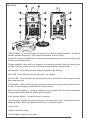
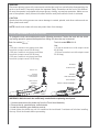
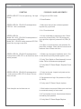
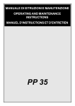
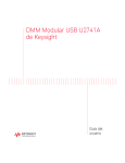
PR-111, PR-112 & PR-113 Inverter Plasma Cutter Series Punktschweißgerät Resistance Spot Welder Kurzanleitung Instruction Manual Inst Version 1.0 All Info Copyright © Pro Spot International Inc. About Pro Spot Pro Spot International, Inc., based in Carlsbad, California, manufactures resistance spot welding equipment specializing in applications for the collision repair industry. The company began in 1986. The company owns and manages an on site machine shop, research & development department, a fabrication facility and production lines for the various welders. Pro Spot International exports its products worldwide, export sales are managed through our headquarter office. The company owns numerous patents for our ingenious application tools, machines, and procedures. Pro Spot training and services Pro Spot Distributors and Sub-Distributors are carefully selected and are well trained in the collision repair industry. We offer technical and service education at our world wide training facilities at regular intervals so your local distributor will always be up to date and able to pass on the latest in spot welding technology to our customers. Customer service is an important part of any investment and our distributors and sub-distributors will be there to support your technical and service needs. We have a great customer service record, we intend to keep it that way. Pro Spot is certified by CASE and a member of the ICAR Industry Training Alliance Contact Information Pro Spot International, Inc. U.S.A. www.prospot.com 5932 Sea Otter Place Carlsbad, CA 92010 2 Phone: +1 760-407-1414 Toll free (US only): 877- PRO SPOT Fax: 760-407-1421 E-Mail: [email protected] CAUTION! BEFORE INSTALLING, OPERATING OR CARRYING OUT MAINTENANCE ON THE PLASMA CUTTER, READ THE CONTENTS OF THIS MANUAL CAREFULLY, PAYING PARTICULAR ATTENTION TO THE SAFETY RULES. In the event of these instructions not being clear, please contact your supplier. CONGRATULATIONS ON YOUR NEW PURCHASE! YOU ARE NOW IN THE POSSESSION OF ONE OF THE SAFEST AND MOST TECHNOLOGICALLY ADVANCED PLASMA CUTTERS ON THE MARKET. FOLLOW OUR SUGGESTIONS AND YOU WILL BE GUARANTEED SAFE AND PROBLEMFREE OPERATION. SAFETY RULES AND GENERAL WARNINGS INTRODUCTION Your plasma cutting unit is ¿tted with sophisticated safeguards which block functioning and therefore the cutting operations until all the safety conditions are present. The plasma cutting technique requires dangerously high voltage for pilot arc starting and during cutting, therefore the following safety rules must be observed with great care. ELECTRICITY 1-Make sure that the unit is earthed and that the supply line has an adequate earth connection. 2-Make sure that the work bench has a satisfactory earth connection. 3-Avoid contact between the metal bars being cut and bare skin or damp clothes. 4-Do not lean on the piece being cut or hold it in your hands. 5-Do not carry out cutting operations in damp environments or on wet surfaces. 6-Do not use the unit if the torch or cables appear damaged. 7-Always turn the unit off before replacing the electrode, the nozzle or the spreader tip of the torch. 8-Always switch the unit off and remove the power cable from the mains socket before carrying out any maintenance inside the unit. CAUTION! Repairs, maintenance and operation of the unit should be carried out by trained personnel who are aware of the risks caused by the high voltage needed to operate the plasma cutting unit. The operator should work in compliance with current standards and abide by all safety regulations. CAUTION! If during the cutting operation a slight electric shock is felt, stop work immediately and do not use the unit until the fault has been discovered and resolved. EYE AND BODY PROTECTION One of the hazards during the cutting process is the emission of electromagnetic waves due to the electric arc. The length of these waves ranges from infrared to ultraviolet. If these rays hit the eyes, they can cause various complaints such as conjunctivitis, burns to the retina, deterioration of sight, etc. Moreover a high concentration of ultraviolet rays can burn the skin. It is, therefore, extremely important that the operator uses adequate safety equipment and clothing, such as: 14 1-Split or leather gloves 2-Split or leather aprons 3-Shin-guards 4-Safety shoes 5-Safety mask (or even better helmet) large enough to cover the whole of the face, equipped with safety lenses able to ¿lter all the radiation and reduce the intensity of the light absorbed by the eye. CAUTION! Never, under any circumstances, look at an electric arc without eye protection. CAUTION! A further hazard for eyes is the risk of splinters or particles which may be detached during the cutting operations or during grinding, brushing or hammering away of the scale. Always wear goggles or protective shields with transparent lenses during these operations to prevent splinters or other foreign bodies from entering the eye. IMPORTANT: safety screens should be installed around the cutting area to protect other people, who may be working in adjacent areas, from the radiation given out by the arc. CUTTING FUMES AND GASES Harmful fumes and metallic powders are produced during the cutting operation. Metals which are painted or coated or which contain mercury, cadmium, zinc, lead and graphite may produce harmful concentrations of toxic fumes during cutting. To protect the operator or other persons from exposure to possible toxic fumes, fume respirators should be worn and work areas should be adequately ventilated. When working in enclosed environments, suction units should be ¿tted below the cutting area. CAUTION! When halogenated solvents or degreasing agents are present, the material to be cut should be cleaned properly to prevent the formation of toxic gases. Some chlorinated solvents may decompose in the presence of the radiation given out by the arc and may generate phosgene gas. FIRE HAZARDS 1-Prevent sparks or hot scale from producing Àames 2-Remove inÀammable or combustible materials from the cutting area. 3-Make sure that ¿re-¿ghting equipment is located near the work area. 4-Situate the unit in an area where the air can be sucked in and exhausted from the grilles on the panel CAUTION! Do not cut fuel or lubricant containers even if these are empty. Do not cut containers or casings which contain inÀammable material. Never cut in environments which are polluted by inÀammable gas or combustible liquid vapours (such as petrol). 15 NOISE Noise is generated during the cutting process. The noise level depends on the cutting parameters used. CAUTION! Noise can damage hearing Wear adequate hearing protection. BURNS The operator should be adequately protected during cutting operations. This should be routine practice. CAUTION! Do not point the torch jet at people or foreign bodies. EMC Before installing the plasma cutting unit, carry out an inspection of the surrounding area, observing the following guidelines: 1-Make sure that there are no other power supply cables, control lines, telephone leads or other equipment near the unit. 2-Make sure that there are no radio receivers or television appliances. 3-Make sure there are no computers or other control systems. 4-Make sure that there is no-one with a pacemaker or hearing aid in the area around the unit. 5-Check the immunity of any other equipment operating in the same environment. In certain cases additional protective measures may be required. Interference can be reduced in the following ways: 1-If there is interference in the power supply line, an E.M.C. ¿lter should be inserted between the mains and the unit. 2-The output cables of the unit should be shortened; these should be kept close together and stretched along the ground. 3-All the panels of the unit should be correctly closed after carrying out maintenance. GENERAL INFORMATION PLASMA ARC AND BASIC PRINCIPLES FOR THE PERFORMANCE OF PLASMA CUTTING ¥ ¥ ¥ ¥ ¥ ¥ Plasma is a gas that is heated to an extremely high temperature and ionised so that it becomes a conductor of electricity. This cutting procedure utilises the plasma to transfer the electric arc to the metal workpiece, which is melted by the heatand then separated. The torch uses compressed air from a single source, for both the plasma and cooling and protective gas. The start of the cycle is determided by an arc, called the pilot arc, which is struck between the mobile electode(negative polarity) ab dthe torch nozzle (positive polarity) due to the short circuit between these two elements. When the torch is brought into direct contact with the workpiece to be cut (connetcted to the positive polarity of the power source) the pilot arc is transfered between the electrode and the workpiece itself thus striking a plasma arc, also called cutting arc. The duration of the pilot arc is set in the fatcory at 3 seconds; if the transfer has not been made within this time, the cycle is automatically stopped except for the cooling air which is kept on. 16 POWER SUPPLY CONNECTION The machine must be connected to a Line-Neutral system with a “PE” protected grounding wire. Check that the relevant socket terminal is actually connected to the distribution system grounding. CONNECTION TO GROUND CABLE Connect the dinse plug to the socket and the work cable clamp to the piece to be cut or to the metallic workbench. Take following precautions: ¥ Verify that there is a good electrical contact particularly if insulated or oxidated coated sheets are cut. ¥ Make ground connections as close as possible to the cutting area. The use of the metallic structures which are not part of the workpiece, such as the return cable of the cutting current, may endanger the safety system and give poor cutting results. ¥ Do not make a ground connection on the piece which has to be removed. TORCH CONNECTION WARNING!: Before starting the cutting operations verify that the parts are properly assembled by inspecting the head of the torch as shown on paragraph “Torch Maintenance” LOCATION AND HANDLING OF THE POWER SOURCE ¥ ¥ ¥ ¥ Choose location verifying that there is a good air Àow and no dust, smoke or gas is present. Make sure that obstacles do not prevent the cooling air Àow out of front and rear openings of the machine. Arrange an open space of at least 5m around the machine. In the case the machine has to be moved, always disconnect the plug from the outlet and gather the cables and pipes so as not to damage them. COMPRESSED AIR A source of clean, dry air or nitrogen must be supplied to your plasma cutting unit. The supply pressure must be between 72.5 and 150 psi (5 and10.3 bar). The Àow rate is approximately 3.5 cu.ft./ min. (100L/min.). Failure to observe these precautions could result in excessive operating temperatures or damage to the torch. An air regulator is included with the unit with optimum pressure setting set to 65 PSI, 4.5 Bar. Note: the regulator should never be set above 6 bar. MANUAL PURGE Oil in the air is a severe problem and must be avoided. The unit is also equipped with an air ¿lter which captures water and oil vapor. Model PR-111: 30A - 40A: The vapor collected can be drained out turning the drain knob located on the air ¿lter. Three Position Drain knob, select the desired position: 1. Open 2. Open when no air pressure, closed when air pressure. The drain knob should not be left in this position during cutting operations. 3. Closed PR-112/113: Model 45A: water contained water contained in the ¿lter in the glass ¿lter can glass be drained can be drained by pushing by pushing upward the drain connector. upward the drain connector. Note: The unit will not operate if the input air pressure is below 55 PSI, 3.8 Bar. 17 FUNCTIONS 30A - 40A MODEL PR-111 1.ON/FF Switch – In the ON position the machine is ready for normal operation. All system control circuits are activated. OFF position deactivates control circuits. 2.Output Current Knob - Adjusts the cutting current supplied by the machine according to the thickness of material/speed. 3.Green LED– Turns ON when input voltage is applied within normal range – blinks slowly when input voltage goes above 260Vac, or below 180Vac. 4.Red LED–Turns ON when torch is triggered. Blinks quickly during 3 second safety pre-Àow prior to pilot arc ignition. Blinks slowly if cutting arcs not initiated after 3 second pilot arc ignition. 5.Yellow LED– Turns ON when the thermal protection is activated. Blinks slowly when the under pressure protection is working (the pressure is under 3,8 Bar). 6. Air regulator - Adjusts the input air pressure - pull upward to unlock - nominal air pressure setting is 4,5 Bar. Note: the regulator should never be set above 6 Bar. 7.Compressed air connection 8. Input cord 9. Work cable with clamp 10. Torch (with a trigger security cap) 18 45A MODEL PR-112/113 1.ON/FF Switch – In the ON position the machine is ready for normal operation. All system control circuits are activated. OFF position deactivates control circuits. 2.Output Current Knob - Adjusts the cutting current supplied by the machine according to the thickness of material/speed. 3.Digital Ammeter - when unit is on views the set cutting current when unit is on, during pilot arc time views the pilot arc current and during cutting views the cutting current. 4.Green LED – Turns ON when input voltage is applied to the machine. 5.Red LED –Turns ON when pilot or cutting arcs are initiated. 6.Yellow LED – Turns ON when the thermal protection is activated or when voltage exceeds with compressed air 7.Yellow LED – Turns on when the under pressure protection is working (the pressure is under 3,8 Bar) or when voltage exceeds without compressed air. 8.Torch Gas Purge Button – Allows to remove any condensation that may have accumulated in the torch and leads while the system was shut down. 9. Air Pressure Gauge – shows the input air pressure 10.Air regulator - Adjusts the input air pressure - pull upward to unlock - nominal air pressure setting is 4,5 Bar. Note: the regulator should never be set above 6 Bar. 11.Input cord 12.Work cable with clamp 13.Torch (with a trigger security cap) 19 CUTTING OPERATION PRELIMINARIES WARNING: unplug the unit from the power supply before assemble or disassemble piled parts, single parts, parts of the torch, torch assemblies or cables. ¥ Check and follow instructions as foreseen in the paragraphs “Safety and Installation” of the present instructions manual. PARTS OF THE TORCH ¥ Check the torch for proper assembly. Install proper torch parts for the desired application (refer to Section called Torch Consumable Parts Selection). NOTE: The power supply will not operate unless the torch shield cup is fully seated against the PIP (Parts in Place) pins in the torch head. INPUT POWER ¥ Check the power source for proper input voltage. ¥ Make sure the power source meets circuit protection and wiring requirements. ¥ Plug unit in and close main disconnect switch to supply primary power to the system. GROUND CABLE ¥ Check for a solid ground cable connection to the workpiece. AUTOMATIC PURGE SYSTEM 30A - 40A model ¥ Place the ON/OFF switch to the ON position. The ON light will Àicker momentarily as the system powers up and then stays on. Activate the torch button to initiate gas purge (pre-Àow) to remove any condensation that may have accumulated in the torch and leads while the system was shut down. When the gas purge is complete, pilot arc will be initiated. 45A model ¥ Place the ON/OFF switch to the ON position. Activate the torch button to initiate gas purge (preÀow) to remove any condensation that may have accumulated in the torch and leads while the system was shut down. When the gas purge is complete, pilot arc will be initiated. To cool torch handle or to further remove condensation in the torch and leads push the torch gas purge button on the front panel of the unit. WARNING Do not initiate pilot arc during adjustment. CHECKING AIR QUALITY ¥ To check air quality, deactivate the torch (post-Àow) and place ¿lter lens in front of the torch. Any oil or moisture in the air will be visible on the lens. DO NOT initiate pilot arc while checking air quality. 20 CUTTING A. Cutting with a Hand Torch ¥ ¥ The torch can be comfortably held in one hand or steadied with two hands. Choose the technique that feels most comfortable and allows good control and movement. Position the index ¿nger or thumb to press the control switch on the torch handle. For edge starts, hold the torch perpendicular to the workpiece with the front of the tip on the edge of the workpiece at the point where the cut is to start. - Fig. A. For piercing, angle the torch slightly to direct sparks away from the torch until the pierce is complete. Fig. B Fig. A ¥ ¥ ¥ ¥ Fig. B For drag cuts keep the torch in contact with the workpiece. For standoff cutting, hold the torch 2-3 mm from the work. With the torch in starting position, press the control switch. After an initial gas purge (pre-air), the pilot arc will come on and remain on for 3 seconds until the cutting arc starts. Once on, the main arc remains on as long as the control switch is held down, unless the torch is withdrawn from the work or torch motion is too slow. Keep moving while cutting. Cut at a steady speed without pausing. Maintain the cutting speed so that the arc lag is about 30° behind the travel direction. Fig. C Fig. C If the cutting arc is interrupted, and the torch trigger is still pressed, the pilot arc comes back on automatically for 3 seconds. To shut off the torch simply release the control switch. When the switch is released a post-Àow will occur. If the torch trigger is pressed during the post-Àow, the pilot arc will restart. B. Piercing with a Hand Torch Note: Recommended maximum piercing capacity is 2mm. If necessary to make a cut on a metal sheet with a tickness more than 2mm without an edge start, make a hole ø 6mm at least using an electric drill to start cutting. Fig. B Fig. D ¥ When piercing with a hand torch, tip the torch slightly so that blowback particles blow away from the torch tip (and operator) rather than directly back into it. Fig. B ¥ Complete the pierce off the cutting line and then continue the cut onto the line. Hold the torch perpendicular to the workpiece after the cut is complete. Fig. D ¥ Clean spatter and scale from the shield cup and the tip as soon as possible. Spraying or dipping the shieldcup in anti-spatter compound will minimize the amount of scale which adheres to it. C. Grates Cutting To cut grates it is suggestable to set cutting current between 20 - 34A. 21 WARNING Disconnect primary power at the source and wait that the torch has cooled before disassembling the torch or torch leads. Frequently review the Important Safety Precautions at the front of this Manual. Be sure the operator is equipped with proper gloves, clothing, eye and ear protection. Make sure no part of the operator’s body comes into contact with the work piece while the torch is activated. CAUTION Sparks from the cutting process can cause damage to coated, painted, and other surfaces such as glass, plastic and metal. NOTE Handle torch leads with care and protect them from damage. TORCH CONSUMABLE PARTS SELECTION To change the torch consumable parts use the following procedure: Position the torch with the shield cup facing upward to prevent these parts from falling out when the cup is removed. Torch for models PR-111 30A / 40A Use: - 0,90 mm ø nozzle to cut pieces more than 5 mm thick (output current 30-40 Amp) - 0,80 mm ø nozzle to cut pieces more than 5 mm thick (output current 20-30 Amp) - 0,65 mm ø nozzle to cut pieces less than 5 mm thick (output current 10-20 Amp) Torch for model PR-112/113 45A Use: 1,00 mm ø nozzle to cut with output current 40-45 Amp - 0,90 mm ø nozzle to cut with output current 30-40 Amp) SPACER SHIELD CUP SHIELD CUP NOZZLE GAS DIFFUSER ELECTRODE NOZZLE GAS DIFFUSER ELECTRODE TORCH HEAD ASSEMBLY TORCH HEAD ASSEMBLY WORK TABLE WARNING: Wait the torch has sufficiently cooled before replacing torch parts. 1. Unscrew and remove the shield cup from the Torch Head Assembly. 2. Remove the tip, gas distributor, and electrode. 3. Install the electrode, gas distributor, and tip. 4. Hand tighten the shield cup until it is seated on the torch head. If resistance is felt when installing the cup, check the threads before proceeding. 22 OPERATING FAULTS During cutting operations performance faults may arise which are not caused by plant malfunctioning but by other operational faults such as: Insuf¿cient penetration : too high cutting speed; torch is too tilted; piece is too thick; cutting current too low; torch parts are worn out; non-genuine Manufacturer’s parts; Interruption of the cutting arc: cutting speed too slow; excessive distance between torch and workpiece; AC line too low - reduce output current; torch parts are worn out; non-genuine Manufacturer’s parts; work cable is disconnected; Excessive scoria settlement: too low cutting speed (bottom dross); too high cutting speed (top dross); excessive distance between torch and workpiece; cutting current too low; torch parts are worn out; non-genuine Manufacturer’s parts; Tilted cutting (not perpendicular): torch position not correct; asymmetric wear of nozzle hole and/or wrong; assemblage of the torch parts; Excessive wear of nozzle and electrodes: air pressure too low; exceeding system capability (material too thick); contaminated air (humidity-oil); excessive pilot arc arc ignitions in the air; Improperly assembled torch; torch tip contacting workpiece; damaged or loose torch head components; non-genuine Manufacturer’s parts. MAINTENANCE Maintenance can only be carried out on the unit if the person in charge of this operation has the necessary technical knowledge and the correct tools. If this is not the case, contact your nearest service centre. CAUTION! Never access inside the machine (panel removal) or touch the torch (disassemblage) without having disconnected power plug. Any inspection performed under voltage inside the machine or inside the torch may cause severe electric shocks caused by direct contact with parts under voltage. 23 UNIT Keep the cutting or gouging area and the area around the machine clean and free of combustible materials. No debris should be allowed to collect , this could obstruct air Àow to the machine. Inspect the unit every 3-4 months (depending on how often the unit is used) and use compressed air to remove any dust deposits. CAUTION! Only use dry compressed air for cleaning. Do not point the jet of air at the electronic circuits. TORCH Periodically, according to its use or to cutting faults verify wear of the parts connected to plasma arc: Shield Cup: Unscrew manually from head of the torch. Clean throughly abd replace if damaged (burns, distortions or cracks). Verify integrity of superior metal sector (actuator torch safety). Tip: Check wear of plasma arc hole and of inner and outer surfaces. If the hole is widened compared to its original width or if it is damaged, replace tip. If surfaces are particularly oxidated clean them with extra ¿ne abrasive paper. Air Distribution Ring: Verify the are no burns or cracks or that airÀow holes are not obstructed. If damaged, replace immediately. Electrode: Replace electrode when crater settling on emitting surface is about 2mm. WARNING! ¥ Before making any operation to the torch let it cool at least all along the “postgas” period. ¥ Except for particular cases it is advisable to replace electrode and tip AT THE SAME TIME. ¥ Respect assembly order of torch parts (reserved compared to disassemblage). ¥ Be carefull that distributing is assembled properly. ¥ Reassemble shield cup screwing tightly and manually. ¥ Never assemble shield cup without having assembled electrode distributing ring and tip beforehand. ¥ Timely and appropriate control procedures on torch parts are essential for safety and functionality of the cutting system. TORCH BODY, HANDLE AND CABLE ¥ These parts usually need no particular maintenance with the exception of a periodic inspection and an accurate cleaning to be made WITHOUT THE USE OF SOLVENTS. In case of damages to the insulation such as breaks, cracks and burns or even a loosening of electric coonductors, the torch CANNOT BE USED FURTHER SINCE SAFETY CONDITIONS HAVE NOT BEEN RESPECTED. IN THIS CASE, REPAIRING (EXTRAORDINARY MAINTENANCE) CANNOT BE MADE ON SITE BUT NEEDS TO BE DELEGATED TO A SERVICE CENTER TO MAKE SPECIAL REST TRIALS AFTER REPAIRING HAS BEEN EXECUTED. In order to keep the torch and the cable ef¿cient it is necessary to follow these precautions: ¥ DO NOT touch torch and cable with warm or hot parts. ¥ DO NOT strain the cable. ¥ DO NOT move the cable on sharp edges or abrasive surfaces. ¥ gather the cable in regular coils if it is too long. ¥ DO NOT step on the cable. COMPRESSED AIR FILTER The unit is equipped with a ¿lter for the compressed air. This ¿lter is ¿tted with a knob for the manual drain of the condensation. Purge periodically to remove the water/oil in the ¿lter by following the instructions of paragraph “Compressed air”. 24 TROBLESHOOTING SYMPTOM POSSIBLE CAUSE AND REMEDY GREEN LED OFF, Fan not operat-ing. No Input 1. Plug unit into 230V outlet. Power. 2. Reset Breaker. GREEN LED ON, YELLOW Overtemperature LED ON. Unit is overheated. 1. Make sure the unit has not been operated beyond duty cycle limits. 2. Air Flow obstructed. GREEN LED ON, Model 30A - 40A - YELLOW Overtemperature / under pressure LED blinks. Model 45A - YELLOW under pressure LED ON. No air Àow in purge or pre-Àow. 1. Air not connected or pressure too low. Check source for at least 5 Bar (72.5 PSI) during purge or pre-Àow, adjust air pressure to 4,5 Bar (65 PSI). 2. Air ¿lter or air line blocked, torch blocked. Replace ¿lter cartridge. Check that air line and torch leads are free of twists and kinks. GREEN LED ON, YELLOW Overtemperature / 1. Shield cup not properly installedon torch. Cheunder pressure LED OFF, no air Àow when torch ck that shield cup isfully seated against torch. switch pressed. 2. Faulty Torch Switch or Parts Assembly in torch holder. Refer to Maintenance paragraph. 3. Faulty Main PC Board Repair / Replace Power Supply. GREEN LED ON, YELLOW Overtemperature / under pressure LED OFF. Air Àows, Pilot arc does not start. 1. Faulty torch parts. Inspect torch parts and replace if necessary. 2. Gas pressure too high. Set pressure to 65 psi (4.5 BAR). 3. Faulty main PC Board. Repair /replace. Torch has pilot arc but does not cut. 1. Work lead not connected. Make sure work lead is connected securely to bare metal. 2. AC input power too low. Use shortest distance to breaker panel possible. 3. Faulty Main PC Board.Repair/Replace. 25 LISTA RICAMBI TORCIA / TORCH PARTS LIST / LISTA DE REPUESTOS DE LA ANTORCHA / LISTE PIÈCES DE RECHANGE DE LA TORCHE PT40-60 01 CORPO TORCIA TORCH HEAD 1 02 ELETTRODO ELECTRODE 1 03 DIFFUSORE AIR DIFFUSER 1 04 CAPPA 1,0 (40-45A) TIP D.1,0 (40-45A) 1 04 CAPPA 0,9 (30-40A) TIP D.0,8 (30-40A) 1 04 CAPPA 0,8 (20-30A) TIP D.0,8 (20-30A) 1 04 CAPPA 0,65 (10-20A) TIP D. 0,65 (10-20A) 1 05 UGELLO SHIELD CUP 1 06 CHIAVE ELECTRODE WRENCH 1 07 IMPUGNATURA+MICRO HANDLE+MICRO 1 08 MICRO MICRO 1 09 FASCIO CAVI CABLE ASSEMBLY 1 MODELLO / MODEL 45A 10 DISTANZIALE SPACER 1 Da usare solo con correnti di taglio superiori a 35A - to be used only with cutting current over 35A 01 CUERPO ANTORCHA TÈTE DE LA TORCHE 1 02 ELECTRODO ELECTRODE 1 03 DIFUSOR AIRE ANNEAU DE DIFUSION 1 04 TOBERA 1,0 (40-45A) BEC D.1,0 (40-45A) 1 04 TOBERA 0,9 (30-40A) BEC D.0,8 (30-40A) 1 04 TOBERA D.0,8 (20-30A) BEC D.0,8 (20-30A) 1 04 TOBERA D. 0,65 (10-20A) BEC D. 0,65 (10-20A) 1 05 BOQUILLA PROTEC. EXT. COUPELLE BLINDÉE 1 06 LLAVE PARA ELECTRODO CLÈ POUR ELECTRODE 1 07 EMPUÑADURA + MICRO POIGNÈE + MICRO 1 08 MICRO MICRO 1 09 HAZ DE CABLES FAISCEAU DE CÂBLES 1 MODELO / MODÈLE 45A 10 DISTANCIADOR ENTRETOISE 1 para utilizar solo con corriente de corte superior a los 35A - à utiliser suelement avec courant de coupe superieur à 35A 50 SCHEMA ELETTRICO / WIRING DIAGRAM / ESQUEMA ELECTRICO / SCHÉMA ÉLECTRIQUE - MOD.30A 51 ESPLOSO / PARTS DRAWING / DESPIECE / VUE ÉCLATÉE - PR-111 MOD.30A LISTA RICAMBI / PARTS LIST / LISTA DE REPUESTOS / LISTE PIÈCES DE RECHANGE - MOD.30A PR-111 01 01 02 02 03 04 05 06 07 08 09 10 11 12 13 14 15 16 17 18 19 20 21 22 23 PRESSACAVO DADO PER PRESSACAVO TARGA ADESIVA ETICHETTA FRONTALE MANOPOLA POTENZ. GUSCIO FRONTALE DIVISORIO ELETTROVALVOLA PRESSOSTATO MANIGLIA COPERCHIO PRESSACAVO CAVO DI ALIMENTAZIONE TORCIA PLASMA PT-40 PRESSACAVO + GHIERA CAVO DI MASSA PINZA DI MASSA SCHEDA PANNELLO FRON. SCHEDA CONTROLLO MODULO FONDO PIEDINO INTERRUTTORE ON/OFF FILTRO MANOMETRO PER FILTRO CABLE CLAMP NUT FOR CABLE CLAMP REGULATION PLATE FRONT LABEL POTENTIOMETER KNOB FRONT FRAME DIVIDING PANEL SOLENOID VALVE PRESSURE SWITCH PLASTIC HANDLE COVER PANEL CABLE CLAMP INPUT CABLE PLASMA TORCH PT-40 CABLE CLAMP + NUT EARTH CABLE EARTH CLAMP FRONT PANEL P.C. BOARD CONTROL P.C. BOARD COMPLETE P.C. BOARD LOWER PANEL LITTLE FEET ON/OFF SWITCH FILTER FILTER GAUGE 1 1 1 1 1 1 1 1 1 1 1 1 1 1 1 1 1 1 1 1 1 1 1 1 1 01 01 02 02 03 04 05 06 07 08 09 10 11 12 13 14 15 16 17 18 19 20 21 22 23 PASA CABLE TUERCA PASA CABLE ETIQUETA REG. FRONTAL ETIQUETA FRONTAL POMO PARA POTENC. MARCO FRONTAL PANEL INTERNO VALVULA SOLENOIDE PRESOSTATO MANILLA DE PLASTICO PANEL DE COBERTURA PASA CABLE CABLE DE ALIMENTACION ANTORCHA PLASMA PT-40 PASA CABLE + TUERCA CABLE DE MASA PINZA DE MASA CIRCUITO PANEL FRONTAL CIRCUITO DE CONTROL CIRCUITO COMPLETO FONDO PIE CHICO INTERRUPTOR ON/OFF FILTRO FILTRO DEL MANOMETRO PASSE-CÂBLE ECROU POUR PASSE-CABLE ETIQUETTE DE RÉG. FRONT. ETIQUETTE FRONTAL POIGNÉE DU POTENTIOMÈTRE CADRE FRONTAL PANNEAU INTÉRIEUR ELECTROVANNE PRESSOSTAT POIGNÉE COUVERCLE PASSE-CÂBLE CÂBLE DE ALIMENTATION TORCHE PLASMA PT-40 PASSE-CÂBLE + ECROU CÂBLE DE MASSE BORNE DE MASSE CIRCUIT PANNEAU FRONTAL CIRCUIT IMPRIMÉ DE CONTROL CIRCUIT IMPRIMÉ COMPLET PANNEAU DU FOND PETIT PIED INTERRUPTEUR MARCHE/ARRÊT FILTRE FILTRE DU MANOMÈTRE 1 1 1 1 1 1 1 1 1 1 1 1 1 1 1 1 1 1 1 1 1 1 1 1 1 52 SCHEMA ELETTRICO / WIRING DIAGRAM / ESQUEMA ELECTRICO / SCHÉMA ÉLECTRIQUE - MOD.40A PR-111 53 ESPLOSO / PARTS DRAWING / DESPIECE / VUE ÉCLATÉE - PR-111 MOD.40A 54 LISTA RICAMBI / PARTS LIST / LISTA DE REPUESTOS / LISTE DES PIÈCES DE RECHANGE - PR-111 MOD.40A 01 01 02 02 03 04 05 06 07 08 09 10 11 12 13 14 15 16 17 18 19 20 21 22 23 24 25 26 PRESSACAVO DADO PER PRESSACAVO TARGA ADESIVA ETICHETTA FRONTALE MANOPOLA POTENZ. GUSCIO FRONTALE SCHEDA PANNELLO FRON. DIVISORIO ELETTROVALVOLA ELETTROVALVOLA PRESSOSTATO COPERCHIO PRESSACAVO CAVO DI ALIMENTAZIONE MANIGLIA TORCIA PLASMA PT-40 PRESSACAVO + GHIERA CAVO DI MASSA PINZA DI MASSA ETICHETTA TRASFORMATORE SCHEDA CONTROLLO MODULO FONDO PIEDINO INTERRUTTORE FILTRO REGOLATORE MANOMETRO PER FILTRO CABLE CLAMP NUT FOR CABLE CLAMP REGULATION PLATE FRONT LABEL POTENTIOMETER KNOB FRONT FRAME FRONT PANEL P.C. BOARD DIVIDING PANEL SOLENOID VALVE SOLENOID VALVE PRESSURE SWITCH COVER PANEL CABLE CLAMP INPUT CABLE PLASTIC HANDLE PLASMA TORCH PT-40 CABLE CLAMP + NUT EARTH CABLE EARTH CLAMP LABEL TRANSFORMER CONTROL P.C. BOARD COMPLETE P.C. BOARD LOWER PANEL LITTLE FEET SWITCH FILTER FILTER GAUGE 1 1 1 1 1 1 1 1 1 1 1 1 1 1 1 1 1 1 1 1 1 1 1 1 1 1 1 1 01 01 02 03 04 05 06 07 08 09 10 11 12 13 14 15 16 17 18 19 20 21 22 23 24 25 26 PASA CABLE TUERCA PASA CABLE ETIQUETA REG. FRONTAL POMO PARA POTENC. MARCO FRONTAL CIRCUITO PANEL FRONTAL PANEL INTERNO VALVULA SOLENOIDE VALVULA SOLENOIDE PRESOSTATO PANEL DE COBERTURA PASA CABLE CABLE DE ALIMENTACION MANILLA DE PLASTICO ANTORCHA PLASMA PT-40 PASA CABLE + TUERCA CABLE DE MASA PINZA DE MASA ETIQUETA TRANSFORMADOR CIRCUITO DE CONTROLO CIRCUITO COMPLETO FONDO PIE CHICO INTERRUPTOR ON/OFF FILTRO FILTRO DEL MANOMETRO PASSE-CÂBLE ECROU POUR PASSE-CABLE ETIQUETTE DE RÉG. FRONT. POIGNÉE DU POTENTIOMÈTRE CADRE FRONTAL CIRCUIT PANNEAU FRONTAL PANNEAU INTÉRIEUR ELECTROVANNE ELECTROVANNE PRESSOSTAT COUVERCLE PASSE-CÂBLE CÂBLE DE ALIMENTATION POIGNÉE TORCHE PLASMA PT-40 PASSE-CÂBLE + ECROU CÂBLE DE MASSE BORNE DE MASSE ETIQUETTE TRANSFORMATEUR CIRCUIT IMPRIMÉ DE CONTROL CIRCUIT IMPRIMÉ COMPLET PANNEAU DU FOND PETIT PIED INTERRUPTEUR MARCHE/ARRÊT FILTRE FILTRE DU MANOMÈTRE 1 1 1 1 1 1 1 1 1 1 1 1 1 1 1 1 1 1 1 1 1 1 1 1 1 1 1 55 LISTA RICAMBI TORCIA / TORCH PARTS LIST / LISTA DE REPUESTOS DE LA ANTORCHA / LISTE PIÈCES DE RECHANGE DE LA TORCHE PR-112/113 PT-80 01 CORPO TORCIA TORCH HEAD 1 02 ELETTRODO ELECTRODE 1 03 DIFFUSORE AIR DIFFUSER 1 04 CAPPA 1,0 (40-50A) TIP D.1,0 (40-50A) 1 04 CAPPA 0,9 (30-40A) TIP D.0,9 (30-40A) 1 05 UGELLO SHIELD CUP 1 06 DISTANZIALE SPACER 1* 07 CHIAVE ELECTRODE WRENCH 1 08 FASCIO CAVI CABLE ASSEMBLY 1 09 IMPUGNATURA+MICRO HANDLE+MICRO 1 * Da usare solo con correnti di taglio superiori a 40A - to be used only with cutting current over 40A 01 CUERPO ANTORCHA TÈTE DE LA TORCHE 1 02 ELECTRODO ELECTRODE 1 03 DIFUSOR AIRE ANNEAU DE DIFUSION 1 04 TOBERA 1,0 (40-50A) BEC D.1,0 (40-50A) 1 04 TOBERA 0,9 (30-40A) BEC D.0,8 (30-40A) 1 05 BOQUILLA PROTEC. EXT. COUPELLE BLINDÉE 1 06 DISTANCIADOR ENTRETOISE 1* 07 LLAVE PARA ELECTRODO CLÈ POUR ELECTRODE 1 08 HAZ DE CABLES FAISCEAU DE CÂBLES 1 09 EMPUÑADURA + MICRO POIGNÈE + MICRO 1 * para utilizar solo con corriente de corte superior a los 40A - à utiliser suelement avec courant de coupe superieur à 40A 56 SCHEMA ELETTRICO / WIRING DIAGRAM / ESQUEMA ELECTRICO / SCHÉMA ÉLECTRIQUE - MOD.45A PR-112/113 57 ESPLOSO / PARTS DRAWING / DESPIECE / VUE ÉCLATÉE - PR-112/113 MOD.45A 58 LISTA RICAMBI / PARTS LIST / LISTA DE REPUESTOS / LISTE DES PIÈCES DE RECHANGE - MOD.45A PR-112/113 01 02 03 04 05 06. 07 08 09 10 11 12 13 14 15 16 17 18 19 20 21 22 23 24 25 26 27 28 29 30 31 32 GUSCIO FRONTALE FRONT FRAME MANOMETRO GAUGE D.40 ETICHETTA FRONTALE FRONT LABEL MANOPOLA POTENZIOM. POTENTIOMETER KNOB INSERTO PER MANOM. GAUGE GROMMET PRESSACAVO CABLE CLAMP INTERRUTTORE 20A SWITCH 20 A COPERCHIO COVER PANEL PRESSOSTATO 3,6BAR PRESSOSTAT 3,6 BAR ELETTROVALVOLA 230V SOLENOIDE VALVE 230V SCHEDA CONTROLLO CONTROL P.C.BOARD DIVISORIO DIVIDING PANEL SCHEDA PANNELO FRONT.FRONT PANEL P.C.BOARD GUSCIO POSTERIORE BACK FRAME FONDO/RETRO BACK/LOWER PANEL MANIGLIA HANDLE MANOPOLA POTENZ. SWITCH KNOB TORCIA PT-80 M4 TORCH PT80 MT4 FERRITOIA PLASTIC AIR-VENT PANNELLO FRONTALE FRONT PANEL PINZA DI MASSA EARTH CLAMP CAVO DI MASSA EARTH CABLE VENTILATORE FAN 230V 50/60HZ SCHEDA MADRE MOTHER P.C.BOARD RESITENZA 4,5OHM RESISTANCE 4,5 OHM IMPEDENZA 23X19CU CHOKE 23X19 CU RELE’ 30A 24VDC RELAY 30A 24VDC TRASFORMATORE TRANSFORMER PIEDINO LITTLE FEET RIDUTTORE M140 REDUCER M140 PRESSACAVO+GHIERA CABLE CLAMP+RING NUT CAVO DI ALIMENTAZIONE INPUT CABLE 1 1 1 1 1 1 1 1 1 1 1 1 1 1 1 1 1 1 1 1 1 1 1 1 1 1 1 1 1 1 1 1 01 02 03 04 05 06. 07 08 09 10 11 12 13 14 15 16 17 18 19 20 21 22 23 24 25 26 27 28 29 30 31 32 MARCO FRONTAL CADRE FRONTAL MANOMETRO D.40 MANOMETRE D.40 ETIQUETA FRONTAL ETIQUETTE FRONTAL POMO PARA POTENC. POIGNÉE DU POTENTIOM. ABRAZADERA PARA MAN. BAGUE POUR MANOMETRE PRENSACABLE PRESSE FIL CONMUTADOR 20 A COMMUTATEUR 20 A PANEL DE COBERTURA COUVERCLE PRESOSTATO 3,6 BAR PRESSOSTAT 3,6 BAR ELECTROVALVULA 230V ELECTROVANNE 230V CIRCUITO DE CONTROL CIRCUIT DE CONTROLE PANEL INTERNO PANNEAU INTÉRIEUR CIRCUITO PANEL FRONTAL CIRCUIT PANNEAU FRONTAL MARCO POSTERIOR CADRE ARRIÈRE FONDO/PANEL POSTERIOR PANNEAU ARRIÈRE/DU FOND MANILLA POIGNÉE POMO PARA CONMUTADOR BOUTON DE COMMUT. ANTORCHA PT-80 MT.4 TORCHE PT-80 MT.4 ASPILLERA GRILLE DE VENTIALTION PANEL FRONTAL PANNEAU FRONTAL PINZA DE MASA BORNE DE MASSE CABLE DE MASA CÂBLE DE MASSE VENTILADOR 230V 50/60HZ VENTILATEUR 230V 50/60HZ CIRCUITO PRINCIPAL CIRCUIT PRINCIPAL RESISTENCIA4,5 OHM RESISTANCE 4,5 OHM IMPEDANCIA 23X19 CU IMPEDANCE 23X19 CU RELÉ 30A 24VDC RELAIS 30A 24VDC TRANSFORMADOR TRANSFORMATEUR PIE CHICO PETIT PIED REGULADOR M140 MANODETENTEUR M140 PASA CABLE + VIROLA PASSE-CÂBLE + BAGUE CABLE DE ALIMENTACION CÂBLE DE ALIMENTATION 1 1 1 1 1 1 1 1 1 1 1 1 1 1 1 1 1 1 1 1 1 1 1 1 1 1 1 1 1 1 1 1 59 NOTES 25 90 NOTES 91 26 NOTES 91 27 Pro Spot international, Inc. 5932 Sea Otter Place Carlsbad, CA 92010 Toll Free (US Only): (877) PRO SPOT Phone: (760) 407-1414 Fax: (760) 407-1421 E-mail: [email protected] Web: www.prospot.com All Info Copyright © Pro Spot International Inc.