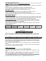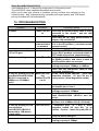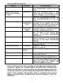
1
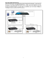
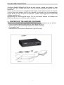
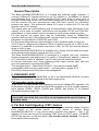
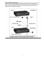
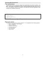
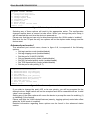
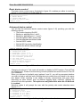
October 2002
LB1350A
LB1351A
Unmanaged ( LB1350A ) and Managed
(LB1351A ) MultiLink Media Converter
User and Installation Guide
CUSTOMER
SUPPORT
INFORMATION
Order toll-free in the U.S. 24 hours, 7 A.M. Monday to midnight Friday: 877-877-BBOX
FREE technical support, 24 hours a day, 7 days a week: Call 724-746-5500
or fax 724-746-0746
Mail order: Black Box Corporation, 1000 Park Drive, Lawrence, PA 15055-1018
Web site: www.blackbox.com • E-mail: [email protected]
1
FCC STATEMENT
FEDERAL COMMUNICATIONS COMMISSION
AND
CANADIAN DEPARTMENT OF COMMUNICATIONS
RADIO FREQUENCY INTERFERENCE STATEMENTS
This equipment generates, uses, and can radiate radio frequency energy and if
not installed and used properly, that is, in strict accordance with the
manufacturer’s instructions, may cause interference to radio communication. It
has been tested and found to comply with the limits for a Class A computing
device in accordance with the specifications in Subpart B of Part 15 of FCC
rules, which are designed to provide reasonable protection against such
interference when the equipment is operated in a commercial environment.
Operation of this equipment in a residential area is likely to cause interference,
in which case the user at his own expense will be required to take whatever
measures may be necessary to correct the interference.
Changes or modifications not expressly approved by the party responsible for
compliance could void the user’s authority to operate the equipment.
This digital apparatus does not exceed the Class A limits for radio noise
emission from digital apparatus set out in the Radio Interference Regulation of
the Canadian Department of Communications.
Le présent appareil numérique n’émet pas de bruits radioélectriques
dépassant les limites applicables aux appareils numériques de la classe A
prescrites dans le Règlement sur le brouillage radioélectrique publié par le
ministère des Communications du Canada.
2
NOM STATEMENT
Normas Oficiales Mexicanas (NOM)
Electrical Safety Statement
INSTRUCCIONES DE SEGURIDAD
1. Todas las instrucciones de seguridad y operación deberán ser leídas antes de que el aparato eléctrico sea operado.
2. Las instrucciones de seguridad y operación deberán ser guardadas para referencia futura.
3. Todas las advertencias en el aparato eléctrico y en sus instrucciones de operación deben ser respetadas.
4. Todas las instrucciones de operación y uso deben ser seguidas.
5. El aparato eléctrico no deberá ser usado cerca del agua—por ejemplo, cerca de la tina de baño, lavabo, sótano mojado o cerca
de una alberca, etc.
6. El aparato eléctrico debe ser usado únicamente con carritos o pedestales que sean recomendados por el fabricante.
7. El aparato eléctrico debe ser montado a la pared o al techo sólo como sea recomendado por el fabricante.
8. Servicio—El usuario no debe intentar dar servicio al equipo eléctrico más allá a lo descrito en las instrucciones de operación.
Todo otro servicio deberá ser referido a personal de servicio calificado.
9. El aparato eléctrico debe ser situado de tal manera que su posición no interfiera su uso. La colocación del aparato eléctrico
sobre una cama, sofá, alfombra o superficie similar puede bloquea la ventilación, no se debe colocar en libreros o gabinetes
que impidan el flujo de aire por los orificios de ventilación.
10. El equipo eléctrico deber ser situado fuera del alcance de fuentes de calor como radiadores, registros de calor, estufas u otros
aparatos (incluyendo amplificadores) que producen calor.
11.El aparato eléctrico deberá ser connectado a una fuente de poder sólo del tipo descrito en el instructivo de operación, o como se
indique en el aparato.
12. Precaución debe ser tomada de tal manera que la tierra fisica y la polarización del equipo no sea eliminada.
13. Los cables de la fuente de poder deben ser guiados de tal manera que no sean pisados ni pellizcados por objetos colocados
sobre o contra ellos, poniendo particular atención a los contactos y receptáculos donde salen del aparato.
14. El equipo eléctrico debe ser limpiado únicamente de acuerdo a las recomendaciones del fabricante.
15. En caso de existir, una antena externa deberá ser localizada lejos de las lineas de energia.
16. El cable de corriente deberá ser desconectado del cuando el equipo no sea usado por un largo periodo de tiempo.
17. Cuidado debe ser tomado de tal manera que objectos liquidos no sean derramados sobre la cubierta u orificios de ventilación.
18. Servicio por personal calificado deberá ser provisto cuando:
A: El cable de poder o el contacto ha sido dañado; u
B: Objectos han caído o líquido ha sido derramado dentro del aparato; o
C: El aparato ha sido expuesto a la lluvia; o
D: El aparato parece no operar normalmente o muestra un cambio en su desempeño; o
E: El aparato ha sido tirado o su cubierta ha sido dañada
3
Black Box®LB1350A/LB1351A
Table of contents
1.
2.
Overview
Planning the network with Black Box®
LB1350A/LB1351A
Content of the shipping container
Product general description
Preferred Port
Far-End-Fault ( FEF )
Parts identification
Installation
Power connection
F/O cabling connection
Twisted Pair cable connection
Configuration switches
Management Black Box® LB1351A
Advanced Features
Troubleshooting
Specifications
page 5
page 7
page 8
page 9
page 10
page 11
page 12
page 12
page 13
page 13
page 14
page 14
page 15
page 16
page 18
Appendix-A: Managing the Black Box® LB1351A
Back Cover page
page 19-37
page 40
3.
4
5
6.
7
8
9
10
11
12
13
14
15
16
page 5
Thank you for purchasing this Black Box®
LB1350A/LB1351A quality converter. We hope
that this guide will help you to obtain the best
results from the device while minimizing
installation time.
If you still need help installing or troubleshooting the Black Box®
LB1350A/LB1351A converter after reading the detailed information in this
guide, please call Black Box Technical Support at 724-746-5500
Note: unless where indicated otherwise, in this guide, Black Box®LB1350A/LB1351A
applies also to Black Box®LB1350A/LB1351A/SC, Black Box®LB1350A/LB1351A/ST,
BlackBox®LB1350A/LB1351A/SM15 and Black Box®LB1350A/LB1351A/SM40
TRADEMARKS
HP and OpenView are registered trademarks of Hewlett-Packard.
UL is a registered trademark of Underwriters Laboratories Incorporated.Any other trademarks mentioned
in this manual are acknowledged to be the property of the trademark owners.
4
Black Box®LB1350A/LB1351A
1 - OVERVIEW
A media-converter may be defined as a device connecting two active network
components point-to-point over a media that is different from the ports of at least one of
these devices.
An ideal media-converter should be a transparent element in the network, and its ports
may be considered as integral parts of the devices interconnected by it.The IEE802.3u
standard defines network span in terms of distances and bit times.
Conventional 100Base-TX/100Base-FX media-converters are based on repeater
technology, and they form a part of the collision domain created by the interconnected
devices. Therefore, the delay they introduce in the network severely affects the allowed
distances. Furthermore, if two class II repeaters (i.e., 2 hubs) are already present in the
same collision domain, then the use of a conventional converter is not allowed as the
repeater count may - in such case - exceed the limits. In all other cases, meticulous
PDV (Path Delay Value) must be performed prior to establishing the possible distances
for both the fiber optic (F/O) and copper segments.
The Black Box®LB1350A/LB1351A family implements a non-repeater, full re-timing
approach. It creates a Buffered Media Domain (BMD) over the F/O link, thereby
eliminating all the above mentioned limitations.
The BMD created by two Black Box®LB1350A/LB1351A devices always operates at
maximum performance - 100Mbps/Full Duplex - while interconnected devices may
operate at different rates and modes. This provides full flexibility when planning a
network.
The Black Box®LB1350A/LB1351A provides 4 (3) TP ports sharing conversion to one
FO port, with the TP ports buffered and VLAN protected between themselves, making
the device an ideal and most economical solution for both FTTH (Fiber-To-The-Home)
and FTTD (Fiber-To-The-Desk) applications.
2- Planning your Network with Black Box®LB1350A/LB1351A
Below you will find a FTTD configuration. The drawing demonstrates the versatility of
the device in terms of interconnecting – trouble-free – other devices.
F/O TO
ENTERPRISE
SWITCH
Black Box
LB1350A/LB1351A
SERVER
HUB (100)
10/100 SWITCH
HUB (10)
In a typical Fiber –to –the - Home ( FTTH ) application
A Black Box®LB1350A/LB1351A will be deployed in a home or building and connected
by fiber to axxess switch.
It may be deployed on a floor of an apartment (office) building and 4(3) apartments
(offices) may be connected to it’s copper ports without the need to verify the type of the
network (device) within the apartment (office).Also a HUB or Switch can be connected
to any TP port according to the required network configuration.
5
Black Box®LB1350A/LB1351A
Note: RJ-45 port No. 4 is a preferred port with enhanced functionality – see section 5.
As each of the Black Box®LB1350A/LB1351A RJ-45 port 4(3) supports: full autonegotiation, auto-polarity and auto-cross, you can simply connect any device to any port
by using a standard straight or crossed cable. In particular, you can connect 10Mbps or
100Mbps devices as well as HDX/FDX devices.
6
Black Box®LB1350A/LB1351A
The Black Box®LB1350A/LB1351A will not only convert signals from copper to fiber
but also from 10 to 100Mbs and HDX to FDX, thus ensuring maximal distance over the
optical link.
All you need to take care of is the Speed and Duplex mode balance across the network:
if one of the local devices is HDX only capable you should force the corresponding
remote device to HDX as well to avoid buffer overflow. Same applies to devices with
10Mbps capability only.
Disregarding the interconnected device F/O link will always operate at 100Mpbs and
FDX (you may force it to HDX as well, if needed )
3 - CONTENTS OF THE SHIPPING CONTAINER
The contents of the Black Box®LB1350A/LB1351A shipping container are as follows:
• One converter Black Box®LB1350A or Black Box® LB1351A
• One AC power cord (excluding shipment to certain countries)
• Four plastic “feet”
• Management serial cable for Black Box® ( LB1351A only)
7
Black Box®LB1350A/LB1351A
4. PRODUCT GENERAL DESCRIPTION
The Black Box®LB1350A/LB1351A may be offered in the following pre-configured
versions :
Multiple 100Base-TX to single 100Base-FX Local Traffic Aggregator with four RJ-45 (switched,
VLAN) ports and duplex SC connectors, Multi-mode - 2km,internal PS
LB1350A-ST Multiple 100Base-TX to single 100Base-FX Local Traffic Aggregator with four RJ-45 (switched,
VLAN) ports and duplex ST connectors, Multi-mode - 2km, internal PS
LB1350A-SM15 Multiple 100Base-TX to single 100Base-FX Local Traffic Aggregator with four RJ-45 (switched,
VLAN) ports and duplex SC connectors, SINGLE-mode - 15km,internal PS
LB1350A-SM40 Multiple 100Base-TX to single 100Base-FX Local Traffic Aggregator with four RJ-45 (switched,
VLAN) ports and duplex SC connectors, SINGLE-mode - 40km,internal PS
LB1351A-SC Multiple 100Base-TX to single 100Base-FX Local Traffic Aggregator with 3 RJ-45 (switched,
VLAN) ports and duplex SC connectors, Multi-mode - 2km, internal PS, SNMP Managed
LB1351A-ST Multiple 100Base-TX to single 100Base-FX Local Traffic Aggregator with 3 RJ-45 (switched, VLAN) ports
LB1350A-SC
and duplex SC connectors, Multi -mode - 2km, internal PS, SNMP Managed
Local Traffic Aggregator with 3 RJ-45 (switched, VLAN) ports
and duplex SC connectors, SINGLE-mode - 15km, internal PS, SNMP Managed
LB1351A-SM40 Multiple 100Base-TX to single 100Base-FX Local Traffic Aggregator with 3 RJ-45 (switched, VLAN) ports
and duplex SC connectors, SINGLE-mode - 40km, internal PS, SNMP Managed
LB1351A-SM15 Multiple 100Base-TX to single 100Base-FX
Feature Summary
•
•
•
•
•
•
•
•
•
•
•
•
10Base-T, 100Base-TX and 100Base-FX modes of operation
Supports FEF feature ( Far-End-Fault ) to test Link integrity.
Comprehensive LED support :Indicators for Link, Activity ( Tx, Rx ) , FDX,
100M, Power status and Link Test
Hardware based 10/100, Full/Half, Flow control ,Auto-Negotiation, Autocross.
Wire speed reception and transmission
Supports 1K Mac addresses
Automatic address learning and address aging ( aging period is 300s)
Frame length range : 64 ÷ 1536 bytes
Vlan tag frames are thus supported and can pass thru the converter
Desktop , shelf ,wall mount installation, or directly in a half 19” rack.
Port based VLAN
VLAN Tagging support and Per port based priority, 802.1p and TOS
port based priority schemes (Black Box® LB1351A) only
Extensive in-band SNMP management (Black Box® LB1351A)
8
Black Box®LB1350A/LB1351A
General Description
The Black Box®LB1350A/LB1351A is a shared and buffered media converter. It
converts 100Base-FX signals received on its F/O interface in 10/100Base-TX signals
and distributes them to 4(3) copper (shielded RJ-45) ports. Each of these ports is
buffered; furthermore, factory set VLAN forms groups each including one copper port
and the common F/O port, providing the users with basic security (no connection
between the users). This architecture allows 4(3) users to share one F/O link with
dramatic (up to 75%) savings.
The copper ports are auto-negotiating and will automatically adapt themselves to the
capacity of the users for highest performance (will negotiate 10/100 and FDX/HDX).
Nevertheless, in some cases it may be necessary to force certain operating modes.
For this purpose, all copper ports may be (individually) forced to 10Mbps/FDX
operation and port #4(3) (the preferred port) may be forced to any desired combination
(altogether 4 combinations) of HDX/FDX and 10/100.
Full front panel diagnostics provide information on the operation mode of every port.
The F/O port is configured by default to FDX but if desired may be set to HDX as well.
However it is essential to remember that when in HDX, the F/O link maximal distance
drops to 412m or less.
The Black Box®LB1350A/LB1351A is available with a variety of multi-mode and singlemode interfaces with distance ranging from 2km to 40km.
The Black Box®LB1350A/LB1351A is packaged in a rugged “half rack” enclosure
allowing elegant and safe deployment in a variety of environments: desktop, 2 units on
a 19” rack-shelf or within a standard “half 19” rack (optional brackets required).
Its internal, high-power auto- range switching power supply ensures easy, safe and
error-free deployment and enhanced MTBF.
The managed version – Black Box® LB1351A – provides full in-band SNMP
manageability (both monitoring and control) - see Appendix A ( pages 19-37 )
Port priority schemes are also a part of the management.
5. PREFERRED PORT
TP port #4 of the Black Box®LB1350A (or #3 of the Black Box® LB1351A) provides
additional functionalities comparing to the other copper ports.
Full operation mode selection
While all the TP ports provide auto-negotiation and forced 10Mbps/FDX operation, this
preferred port may be set via the front panel DIP switches to force all possible operation
mode options: 10/HDX, 10/FDX, 100HDX and 100FDX. See section 12 for detailed
Dip switches setting ( page 14 ).
Recommendation: use the preferred port for connection of the most critical or
heavy traffic user of the four, even if you do not implement the special features
described above
6. Far End Fault Signaling ( FEF ) feature
When the device detects F/O Link Loss (receive side) it automatically sends a Far End
Fault signal to the remote device. If such device is another Black
Box®LB1350A/LB1351A or any device which supports such feature – then it will
indicate F/O Link Loss as well. By activating TEST mode (by TEST switch - #8 MODE
SETUP Dip switches on the front panel ) this function may be disabled .The picture
below depicts this functionality.
9
Black Box®LB1350A/LB1351A
If there is a fault in the outgoing path and the remote device is FEF compliant (see
below) then the F/O LINK LED will go OFF on both the local and remote devices. In this
way we avoid the possibility of having a FX Link ON indication at one end while, in
reality one of the data path is disrupted.
10
Black Box®LB1350A/LB1351A
7 - PARTS IDENTIFICATION
1
2
3
4
5
6
7
8
9
10
11
12
13
14
Black Box®LB1350A
Power ON LED
TEST mode LED
Duplex SC connector
F/O FDX mode LED
F/O Link/Activity
Black Box®LB1351A
Power ON LED
TEST mode LED
Duplex SC connector
F/O FDX mode LED
F/O Link/Activity
Mode Setup (DIP)
switches
N/A
Mode Setup (DIP)
switches
Mini DIN RS-232
connector
Receive LED
Ready LED
N/A
RJ-45 ports 1 to 3
Link/Activity ports 13 LED
Full Duplex ports 1-3
LED
100Mbps ports 1-3
LED
N/A
N/A
RJ-45 ports 1 to 4
N/A
Link/Activity ports 1- 4
LED
Full Duplex ports 1-4
LED
100Mbps ports 1-4
LED
COMMENTS
Linked to DIP switch #8
Lit steady – LINK ON;
blinking - receive
See section 12 for details
( page 16 )
Management activity
Management module OK
Lit steady – LINK ON;
blinking - receive
Lit when FDX detected or
forced
Lit when 100Mbps
detected or forced
NOTE: All Duplex mode LEDs – blinking indicates collisions on respective port (in HDX
mode only)
11
Black Box®LB1350A/LB1351A
8 - INSTALLATION
For Half-Rack Mount installation:
Use the optional bracket kit, affix it to the unit. Then use 4 standard bolts and nuts (not
supplied), and fasten well to the rack.
Make sure to leave a gap of at least 2-3cm above the unit.
For wall mount installation
Three suitable holes on the back of the Black Box® LB1350A/LB1351A permit wall
mount Installation either horizontally (preferred) or vertically.
Two holes are 188mm apart for horizontal wall mount installation, for vertical wall mount
installation the two holes are 107mm apart.
Use two suitable screws having heads diameter less than 8mm
For Desktop use: Affix the supplied plastic “feet” (after peeling off the adhesive
protecting sheet) to the bottom of the devices, with each “foot” approximately 1 cm from
each edge.
Place the device horizontally on a hard, clean surface (desk, shelf, etc.), leaving free
space around it for natural ventilation. Avoid putting the device on other active, heat
generating equipment and avoid putting such devices on the Black
Box®LB1350A/LB1351A
19” Rack installation
Use a standard flat shelf, install it in the rack and place one or two Black
Box®LB1350A/LB1351A side by side on the shelf. Make sure to leave a gap of at least
2-3cm above the unit.
9 - POWER CONNECTION
CAUTION: When connecting a device to an AC) power outlet,
always first connect the cord to the device, and ensure that it
is securely fastened. Only afterward connect the cord to the
wall outlet .Make sure to use grounded ( 3 way ) outlets.
For each country Black Box provides with the product an appropriate power
supply cord which is safety approved in accordance with such country’s
National Electric Code
Black Box®LB1350A/LB1351A
Connect AC line voltage at the rear of the converter, using the included power cord. The
Black Box®LB1350A/LB1351A will accept any line voltage from 100 to 240 VAC, 50-60
Hz.
There is no ON/OFF switch on the device. When the power is connected to the device,
the device is ON. This will be indicated by the POWER LED ON.
Important: following any connection or setup change (sections10,11,12
below) you must reset the device by either using S9 or by disconnecting
power and reconnecting it after few seconds
12
Black Box®LB1350A/LB1351A
10 - FIBER OPTIC CONNECTION
The Black Box®LB1350A/LB1351A is equipped with either a pair of SC-type
connectors ( MM or SM models ) or ST connectors ( MM models only )
Do not remove the protective covers on the fiber connectors until you are ready to
connect the fiber optic cables. Power should be connected before attaching the fiber
optic cables. When dealing with fiber optic cables, it is essential to ensure that the TX at
one end of the link is connected to the RX at the other end of the link. Some duplex
fiber optic cables are color coded to help monitor the direction of data transmission. If
the fibers are not coded, special attention must be paid to ensure a proper connection.
CAUTION
Radiation emitted from a fiber optic connector may
be hazardous to human vision. Therefore, the
following rules must be strictly observed
All single-mode (SM) models are
CLASS I LASER PRODUCTS
And must be handled with special care
. When not in use, keep the fiber optic connector
closed using its protective cover.
Never stare directly into the fiber optic connector
of a powered device or into the end of a fiber
connected to it.
11 - TWISTED PAIR CABLE CONNECTION
As each of the Black Box®LB1350A/LB1351A RJ-45 4(3) ports supports: full autonegotiation, auto-polarity and auto-cross, you can simply connect any device to any port
by using a standard straight or crossed cable. You may need to force an operation
mode other than auto-negotiation; refer to section 12 ( “ Configuration Switches “ page
14 ).
Use a shielded Cable Type 5 or higher grade, up to 100m (330ft) long to ensure proper
operation at 100Mbps.
On Black Box®LB1350A/LB1351A with the Auto-Cross feature, the RJ45 port has the
intelligence to sense the type of cable which has been connected to it and will
automatically configure itself to either MDI or MDI-X mode of operation.
13
Black Box®LB1350A/LB1351A
12 – CONFIGURATION SWITCHES
The Black Box®LB1350A/LB1351A) is equipped with an array of 10 DIP switches
marked “MODE SETUP” that facilitate the proper setting of the device and individual
ports. See section 7 ( “ Parts Identification ” page 11 )
Shaded areas indicate factory default setting.
Use a small tool (pen tip or a tiny flat-head screwdriver) to set the switches.
Switch
No.
Function
Up Position
Down
Position
1
TP port #1
operation mode
TP port #2
operation mode
TP port #3
operation mode
TP port #4
operation mode
10Mbps/FDX
(forced)
10Mbps/FDX
(forced)
10Mbps/FDX
(forced)
Disable A/N
Autonegotiation
Autonegotiation
Autonegotiation
Autonegotiation
10Mbps
100Mbps
Half
Full
Half
Full
8
TP port #4
Speed
TP port #4
Duplex mode
F/O port Duplex
mode
Far End Fault
9
Reset
Enabled
(Normal)
Reset
10
VLAN ports
default setting
Disabled
(Test)
Normal
operation
mode
Disable
2
3
4
5
6
7
Enable
Comments
Not Connected in Black Box®
LB1351A
TP Port #2 in Black Box®
LB1351A
TP Port #3 in Black Box®
LB1351A .The port is in AutoNegotiation mode by default
See section 6
Reset momentarily (move
down then up) following
any setup change
By default each TP port
with the F/O port forms a
separate security VLAN.
In LB1351A, the internal
management port is also
included in each VLAN.
13 – MANAGEMENT (Black Box® LB1351A)
The Black Box® LB1351A is a SNMP managed device. Main features are:
a. Out-of-Band with any terminal emulation program ( RS232 port, front panel )
b. In – Band management.
c. Supported MIBs : MIB II ( RFC1213 and RFC1215 ), RFC2474 and
private MIBs.
d. The Black Box® /LB1351A converters may be managed from any SNMP
management station running popular management platforms ( e.g. HP OpenView,
SNMPc, etc )
Refer to Appendix-A “Managing the Black Box® LB1351A” ( pages 19-37 ) of this
guide for the complete setup management procedures )
14
Black Box®LB1350A/LB1351A
14. ADVANCED Features: Port Priority Schemes
The Black Box® LB1351A (only)can determine priority through three different
means.
The first method is a simple per port priority, the second is via the
802.1p frame tag and the third is by viewing the DSCP ( TOS ) field in the
Ipv4 header. Two priority levels are deployed ( High and Low )
Per Port Priority
General priority can be specified on a per port basis. In this type of priority
all traffic from the specified input port is considered high priority .
This can be useful in IP phone applications mixed with other data types . The IP phone
traffic would be high priority .
802.1p Port Priority
This method works well when used with ports that have mixed data and media flows.
The 802.1p priority tag ( 3 bits ) are used to determine frame priority. The inbound port
examines the priority field in the tag and determines the high or low priority.
VLAN tagging and priority. When frames are sent across the network, there needs
to be a way of indicating to which VLAN the frame belongs. This info is added to
the Ethernet frame in the form of a tag header.
Ethernet Frame Tag Header consists of a Tag protocol identifier ( TPID ) and Tag
control information ( TCI )
Ethernet frame :
SA
DA
6B
6B
4B
TAG
PT
4B
DATA
CRC
2B
Tag Header
TPID
TCI
TPID is the tag protocol identifier which indicated that a tag header is following and
the TCI contains the User priority, canonical format indicator ( CFI ) and the VLAN
ID
TPID
16 b
User priority
3b
CFI
1b
VLAN ID
12b
User priority is a 3 bit field which allows priority information to be encoded in the
frame. 8 levels of priority are allowed, where zero is the lowest and 7 is the highest
priority.(this field is used by 802.1p )
CFI : indicates presence/absence of RIF ( routing info field ) in the 802.3/Ethernet
frames.
The VLAN ID is used uniquely to identify the VLAN to which the frame belongs.
There can be a maximum of 4096 VLANs.
DSCP Port Priority
This is another per frame way to determine outbound priority.
The DSCP ( Differentiated Services Code Point – RFC 2474 ) method uses the
TOS
field in the IP header to determine high or low priority on a per code point basis.
Each fully decoded code point can have either a high or low priority.
The most significant 6 bits of the TOS field are fully decoded into 64 possibilities,(
up to 64 distinct behaviors ) and the resulted singular code is compared against the
corresponding bit in the DSCP register. ( in Black Box® LB1351A unit )
15
Black Box®LB1350A/LB1351A
If the register bit is a 1, the priority is high and if 0, the priority is low.
Thus the DSCP value classifies the packet service level.
When more than one scheme is enabled, priority conflicts are resolved by the
following order : 802.1p based priority overrides port based priority and TOS based
priority overrides 802.1p based priority
15- TROUBLESHOOTING
Problem
Indication
Corrective Action
No power
Power LED not Check that the power supply cable is firmly
lit
connected to the device and the wall
power socket.
Check that the AC input power source is
between 100 and 240VAC.
Network problems
No
On the “mode setup switches”, check that
communication S9 is in the UP position. ( converter normal
on network
operation mode )
Reset the device using S9
Any problem related to port
Set device to TEST mode (S8 Down), reset
4 (3) or F/O port
device (S9).If problem not solved remain in
TEST mode and perform troubleshooting.
TP link not working
Link LED not lit On the “mode setup switch” move S9 to
the DOWN position, and move it back to
the UP position after one second.
Check that the connected device is
working properly at 100Mbps or 10Mbps.
Check that the connection cable is well
connected at both ends.
TP link not working at 100M Both Link LED On the “setup mode switches”, check that
when Black Box®LB1350A
and
respective switches S1 thru S4 are in
LB1351A connected to
100BaseTX LED down position ( Auto-Negotiation mode )
100Mbps or 10/100Mps
not lit
device
Interchange between the suspected port
and another port 1 thru 4
Check that the connected device is
working properly at 100Mbps.
Check the interconnection between the
Black Box®LB1350A LB1351A and the
device.
Use for suspected link the preferred port
and force it to 100Mbps (S4 up, S5 down)
TP link not working at 10M Link LED not lit If suspected port
is 1 thru 3, move
when the Black
respective switch (S1 thru S3)
to up
Box®LB1350A LB1351A
position , if port 4 – move S4 up and S5 up
connected to 10M device
(copper side).
Reset the device using S9
Check that the connected device is
working properly at 10Mbps
16
Black Box®LB1350A/LB1351A
Problem
Black Box®LB1350A or
LB1351A not recognizing
full duplex
Fiber link not working
No Link-Up after failure
Improper network traffic
Indication
Corrective Action
Check the interconnection between the
Black Box®LB1350A LB1351A and the
device.
FDX LED not lit Verify that connected device is FDX
capable and set to FDX properly. If HDX
then the indication is correct and you have
to setup the S7 Dip switch accordingly
Check the interconnection between the
Black Box®LB1350A/LB1351A and the
device.
Link LED
Check that the receive fiber is properly
(100BaseFX) connected to the transmit port of the
not lit
remote fiber device AND the transmit port
to the receive port of the remote device.
Remote device Change to TEST mode (S8 UP) and verify
reports LINK with remote operator to establish whether
DOWN
incoming or outgoing paths failed
Check that the fiber optic power is higher
than -30 dBm on the receive fiber
connector at the Black Box®LB1350A
/LB1351A end.
Check that remote device’s receive port is
properly connected to the transmit fiber
optic port of the Black Box®LB1350A
/LB1351A
Verify FDX mode of the F/O port (S7 Down)
; reset device by S9
F/O LED OFF Disable FEF: Dip switch # 8 in Up position
(section 12 page 14)
Runt and late Reset the device using S9
collision
Check configuration (section 12 ) on the
“mode setup switches”.
Check that both ends of F/O link are set to
same mode (Half Duplex OR Full Duplex).
Check that both sides of UTP connection
are in same mode (10Mbps Half duplex OR
10Mbps full duplex OR 100Mbps Half
duplex OR 100Mbps full duplex).
If the problem persists after carrying out the above procedure, do the
following: replace the installed Black Box®LB1350A LB1351A,with
another similar device and re-perform the requested setup. If that has
solved the problem, send the faulty Black Box®LB1350A/LB1351A for
repair. If the problem still persists, there is probably some sort of
general network failure. Call Black Box Technical Support (Call 724746-5500 ).
17
Black Box®LB1350A/LB1351A
16.Specifications
Standard Compliance
IEEE 802.3u, IEEE802.1p, 100Base-TX, 100Base-FX, 10Base-T, FDX flow control, HDX back pressure
flow control . Supported MIBs: MIB II (RFC1213,RFC1215), RFC2474 ( DSCP ) and private MIBs.
Vlan tagging support, (Black Box® LB1351A )
Conversion Method :BMD (Buffered Media Domain), four (three) ports share one F/O link
100BaseTX ports x 4 (3)
•
•
•
•
•
•
Shielded RJ-45 connector
Half/full duplex support via auto-negotiation or manual (preferred port)
100m over UTP/STP 100ohm cat.5 cable
Auto-polarity correction
MDI/ MDI-X auto crossover support
10BaseT - Dip switches selection
100Base-FX port
• 1310nm multi-mode, SC (ST optional) connectors. Optional Single Mode
• Distance: 2000m (6500ft) when used in pairs (15/40/ km in s/m)
• Output power: -18dBm multi-mode
single-mode: - 16 / -11 dBm respectively
• Input sensitivity:
• multi-mode: -32dbm
• single mode: -30/-33 dBm respectively
• Far End Fault Signaling.
• Full/half duplex dip switch selection
Diagnostics
• F/O port: Link/Activity, FDX
• Each TP port: Link/Activity, FDX,100Mbps
• Power , Test LED ( lit = FEF disabled, off = FEF enabled
Controls
F/O port: HDX/FDX
TP ports 1-3(2): a/n-10M
TP port 4(3): a/n enable/disable, force 10/100/ force HDX/FDX
System: Reset, link test ( enable / disable Far-End- Fault )
Environmental /Physical
Power supply:
Black Box®LB1350A/LB1351A
100 ÷ 240 VAC, 50 ÷ 60 Hz
• Power consumption:
15W max.
• Storage temperature:
-20°÷+ 80°C
• Operating Temperature
0°÷+ 45°C ( 32-113° F )
• Humidity:
10 ÷ 90% non-condensing
• Safety:
UL 1950 ): 1955, EN60950
• Emissions:
FCC part 15 subpart A, class A, VCCI
Class
ICES 003 : 1997, Class A, EMC
Directive 89 / 336/EEC
Dimensions and weight
223x44x150mm ( WxHxD )
600gram
Specifications subject to change without prior notice
18
Black Box®LB1350A/LB1351A
Appendix-A : Managing the Black Box® LB1351A
1.Preface
This appendix provides you with the necessary information for managing the
Black Box® LB1351A Traffic Aggregator (monitor and control).
In order to start managing your Black Box® LB1351A you need to setup the
management module parameters (section 2). In addition you will need to set proper
network connection (section 3) and to install the attached MIB file (section 4).
After the management parameters are set, you can manage the Black Box®
LB1351A in either of two ways: using SNMP (through a standard management
station – section 5) and using a Terminal (section 6).
2.Setting Up Management Parameters
Terminal connection
Have available a PC equipped with any terminal emulation program (any ASCII
terminal).
Use the supplied control cable to connect the converter to the PC: connect the
miniDIN end of the cable to the RS232 port on the converter and the other end to
an available DB9 (male) connector on the PC.
Configure the terminal emulation program as follows:
•
baud rate: 9600
•
parity: none
•
start bits: 1
•
stop bits: 1
•
flow control: none
Start the terminal emulation then reset the device.
Startup screen
After a few seconds you will get the start up screen (figure 2-1).
Note: the parameters appearing in the figures are just examples. Set them to
the values you need.
At this point, you should immediately press any key in order to get to the
management configuration procedure. You will get a notification that will enable you
to modify the current settings by typing ‘m’ (or ‘M’).
At this stage you will be prompted with a series of questions regarding the
management parameters configuration. The configuration procedure screen is
shown here in figure 2-2. Default value for each parameter appears in braces. If you
do not wish to change a certain parameter, simply hit ‘Return’.The different
parameters are explained in detail in figure 2-2. Default value for each parameter
appears in braces.If you do not need to change a certain parameter, simply hit “
Return “.The different parameters are explained in details in figure 2-2.
19
Black Box®LB1350A/LB1351A
Management card configuration
--------------------------------------------------------------------NETWORK PARAMETERS:
------------------IP address on LAN is 192.168.1.99
CONSOLE PARAMETERS:
------------------console channel will use a baud rate of 9600
BOARD PARAMETERS:
----------------Processor
: MPC850, Running at 50Mhz
Board Info
: Management Board
Board memory : FLASH : 4Mbytes
SDRAM : 4Mbytes
Board's Ethernet hardware address : 0:A0:D2:2F:80:82
--------------------------------------------------------------------To change any of this, press any key within 5 seconds
Figure 2-1 – management parameters setup screen
When configuration is complete, the startup screen will appear with the new
parameters. If you still want to change any other parameters, type ‘M’ to modify.
Otherwise type ‘C’ to continue. Configuration parameters will now be saved and the
system will initialize (figure 2-3).
(M)odify any of this or (C)ontinue? [M] m
For each of the following questions, you can press <Return> to select the value shown in braces, or
you can enter a new value.
NETWORK PARAMETERS:
------------------Do you want a LAN interface? [Y]
This board's LAN IP address(0.0.0.0 = RARP)? [192.168.1.99]
Use a subnet mask for the LAN interface? [N] y
Subnet mask for LAN (0 for none)? [0.0.0.0]
Should there be a default gateway for packet routing? [N] y
What is its IP address? [0.0.0.0]
CONSOLE PARAMETERS:
------------------Baud rate for serial channels [9600]
ETHERNET PARAMETERS:
-------------------Do you want to change the board's Ethernet address? [N] y
Byte 0 must be 00
What should byte
What should byte
What should byte
What should byte
What should byte
1
2
3
4
5
be?
be?
be?
be?
be?
[A0]
[D2]
[2F]
[80]
[82]
SNMP PARAMETERS:
---------------Get community [public]
Set community [private]
Trap destination [192.168.1.15]
Trap community [trap]
System name [FibroLAN]
System location [Israel]
System Contact [Shamir]
How long (in seconds) should CPU delay before starting up? [5]
Figure 2-2 – management parameters configuration
20
Black Box®LB1350A/LB1351A
Network parameters
•
IP address: specify here the IP address you wish to assign the management
module. This parameter must be set correctly (according to your network) in
order to remotely control and monitor your device from a management station.
•
Subnet mask: specify the required subnet mask to use within the network.
•
Default gateway: specify the default gateway to be used by the management
module where applicable.
Console parameters
•
Baud rate: set the baud rate of communication between the Black Box®
LB1351A and the terminal. It is recommended to leave this setting at default
(9600baud).
SNMP parameters
•
Get community: specify the get community string for the device.
•
Set community: specify the set community string for the device.
•
Trap destination: specify the IP address of the remote manager that will
receive the traps sent by the Black Box® LB1351A.
•
Trap community: specify the trap community string for the device.
•
System name: specify a name that identifies the device.
•
System location: specify the physical location of the device. Setting this
parameter properly helps to monitor the network and maintain order within it.
•
Contact name: specify the person (most likely system or network administrator)
that is responsible for managing and/or handling the converter.
•
Start up delay: specify how many seconds the management module should
wait between the appearance of the start-up screen and the system
initialization. During this time it is possible to change the management
parameters configuration.
Updating parameter storage. This may take a while...Done
Initialization...
Figure 2-3 – configuration complete; initialization
Your Black Box® LB1351A is now ready to be managed. The Ready LED should now
be lit steady.
Disconnect the control cable and store it properly (unless you wish to manage the
Black Box® LB1351A through a terminal).
21
Black Box®LB1350A/LB1351A
3.Network Connection
One of the conditions that have to be met before you’re able to manage the Black
Box® LB1351A is to have the device connected to a network (IP).
This connection is achieved through the Fiber-Optic port of the device. Naturally, this
port has to be connected to a network, on which the management station resides.
Please note that all management traffic is in-band, along with normal traffic.
At this point your Black Box® LB1351A is ready to be managed by any Network
Manager running on the network. In order to obtain full management functionality over
the Black Box® LB1351A, you should install the MIB file and define the Black Box®
LB1351A object in the management application (see next section).
Important: if you wish to manage the device (and/or other devices in the network) by
connecting the management station directly to one of the device’s RJ-45 ports, you
MUST disable per port VLAN first (switch # 10 to UP position)!
4.Configuring the Management Station
Before you can begin to fully manage the Black Box® LB1351A from a management
station using SNMP, you need to load and compile the MIB file(s), included with the
management module, onto the management station.
In order to accomplish this you need to perform two steps:
Copy the MIB file, supplied with the module, to the default directory that contains all
other MIB files (varies between management software packages).
In your management application, add the new MIB to the already existing list of MIBs
and recompile them.
After MIB installation you should define a new managed object for the Black Box®
LB1351A according to the SNMP parameters you have previously set. The way to
define this object varies from one management application to another.
You have now completed all the necessary preparations required to fully monitoring
and controlling the Black Box® LB1351A from any management station on the
network.
22
Black Box®LB1350A/LB1351A
5.Managing the Black Box® LB1351A
You can monitor and control the Black Box® LB1351A Traffic Aggregator using SNMP
with a management station. This station must have a management application and it
should be connected to the device (via the network).
After the device and management station are connected and running you will be able
to manage your device through the SNMP management application.
Use the management application to view the device’s general information (figure 5-1)
or the MIB tree for detailed status (figure 5-2). In order to monitor the device’s status
you should open the following branch of the tree:
enterprises/fibrolan/fibrolanSNMP/fibrolanAggregator/flAggrLta31m
Through the various parameters given within the Black Box® LB1351A’s MIB, you can
view the complete device status and the ports’ status and you can configure most of
these parameters.
The Black Box® LB1351A is a fully featured traffic aggregator that provides advanced
capabilities such as VLAN tag insertion and stripping and an advanced set of priority
schemes. These features are explained in details later on in the ‘Managing with a
terminal’ section. All settings are also accessible through SNMP and their meaning is
the same (so the complete detailed explanation about each parameter is found only in
the terminal section).
Note: some configuration changes (mainly port connection and disconnection)
require a few seconds to take effect.
23
Black Box®LB1350A/LB1351A
6. Managing with a Terminal
The first option for managing the Black Box® LB1351A Traffic Aggregator is by using a
terminal emulation program. In order to do this you will need a PC (or a terminal) with a
terminal emulation program.
Connect the serial cable supplied with the Black Box® LB1351A between the device
(miniDIN side) and a serial port on the PC with the terminal emulation (on the DB9
side). Start the emulation program and reset the device (recommended).
After system initialization you will get to the device’s main menu.
The main menu
This menu contains a header with the software version, the model of the device
(LB1351A ) and the vendor Black Box.
Following is a two-option menu. See figure 6-1.
Selecting option 1 will invoke the device’s status menu, while option 2 will bring up the
device control menu.
************************************************************
*
*
* Software version: v1.0
*
* Version date:
16/10/02
*
*
*
* Vendor: Black Box
*
* Model: LB1351A
*
*
*
************************************************************
1. Device status
2. Device control
Select (1-2):
figure 6-1 - main menu
The device status menu
This menu contains two options: 1 for basic status and 2 for advanced status. Figure 62 shows the menu. Figures 6-3 and 6-4 show the basic and advanced status
respectively.
Device status:
==============
1. Basic status
2. Advanced status
0. Main menu
Select (0-2):
figure 6-2 - device status menu
24
Black Box®LB1350A/LB1351A
Basic ports' status:
# Type Link Duplex AutoNego Rate Connected
================================================
1 TP
Off
FDX
Disabled 100M
Yes
2 TP
Off
n/a
Enabled
n/a
Yes
3 TP
Off
n/a
Enabled
n/a
Yes
4 FO
Off
FDX
---100M
Yes
================================================
Basic device status:
-------------------VLAN:
enabled
Temperature: 39C
figure 6-3 - basic status
Basic status
This status includes the basic ports’ status and the basic device status.
Basic port’s status gives the following data about each port:
• Port number
• Interface type (TP/FO)
• Link status (On/Off)
• Duplex mode (FDX/HDX)
• Auto-Negotiation mode (enabled/disabled)
• Data rate (10/100M)
• Connection mode (connected/disconnected)
The basic device status includes:
• VLAN mode (enabled/disabled)
• Device’s temperature (in centigrade)
Advanced ports' status:
# Type Tag: Insert Strip VID | Priority: Port 802.1p TOS User
===============================|===============================
1 TP
No
No
0 |
No
No
No
0
2 TP
No
No
0 |
No
No
No
0
3 TP
No
No
0 |
No
No
No
0
4 FO
No
No
0 |
No
No
No
0
Mgmt
No
Yes
222 |
No
No
No
0
===============================|===============================
Advanced device status:
----------------------Test:
Off
Priority ratio:
Always high
Broadcast:
Allow 25% broadcasts
DSCP (63 <- 0):
0x00-00-00-00-00-00-00-00
User priority: code: 0 1 2 3 4 5 6 7
prio: LO LO LO LO HI HI HI HI
figure 6-4 - advanced status
25
Black Box®LB1350A/LB1351A
Advanced status
A port’s advanced status includes, in addition to its number and type:
• Tag insertion mode (Yes/No)
• Tag stripping mode (Yes/No)
• Port’s VID (0-4095)
• Port based priority (Yes/No)
• 802.1p based priority (Yes/No)
• TOS based priority (Yes/No)
• Port’s user priority (0-7)
When tag insertion is enabled on a port it means that any untagged frames coming out
that port will be tagged. The inserted tag will include the ingress port’s VID and user
priority. For example, if port 1’s VID is set to 100 and its priority is set to 4 and the FO
port’s tag insertion is on, then any untagged frame coming on port 1 and going out the
FO port will carry a tag with VID 100 and priority 4.
When tag stripping is enabled, any tagged frame coming on the port, will lose its tag.
Default values are all 0s or No.
The Black Box® LB1351A supports 2 levels of traffic priority: high and low. The
different priority settings enable or disable 3 different types of priority schemes: port
based, 802.1p based and Type Of Service (TOS) based, dealing with DSCP (Diff Serve
Code Points) field values.
When more than one scheme is enabled, priority conflicts are resolved by the following
order: 802.1p based priority overrides port based priority and TOS based priority
overrides 802.1p based priority. Default values are all No.
Please note that the advanced port settings apply to management traffic as well.
Management can be thought of as a virtual, internal port.
The device’s advanced status consists of:
• Test mode (FEF disable/enable)
• Priority ratio (always hi/10:1/5:1/2:1)
• Broadcast protection (allow 25/12/6/3%)
• DSCP codes (64 bits)
• User priority classification (7 priority codes, set as high or low priority)
The test mode is used mainly for maintenance purposes and its meaning is that the
FEF function is disabled (when Test is On). Default value is Test Off.
The priority ration setting controls the priority traffic flow ratio. If for example, set to
always hi, all high priority frames will be forwarded before low priority ones. At 10:1,
after every 10 high priority frames, a single low priority frame will be forwarded and so
on. Default value is always hi.
26
Black Box®LB1350A/LB1351A
The broadcast protection indicates the relative amount of broadcast traffic that will be
forwarded by the Black Box® LB1351A, starting at 25% maximum and down to 3%
minimum. Default value is 25%.
The DSCP codes are represented as a series of 8 bytes, corresponding to 64 bits.
These bits correspond, in turn, to 64 different DSCP codes. If you wish, for instance, to
set code 45 as high priority, then bit 45 in this series needs to be set to ‘1’ (this is done
though the control menus, described later). Default values are all 0s (meaning all codes
are low priority).
The user priority codes are used in conjunction with the 802.1p based priority scheme.
For example, if a tagged frame arrives with a priority code of 6, the Black Box®
LB1351A will look priority code 6 to see if it is set as high or low priority and handle the
frame accordingly. Default values are low priority for codes 0-3 and high priority
for codes 4-7.
The device control menu
The device control menu, shown in figure 6-5, enables the user to change the different
settings and configuration of the Black Box® LB1351A
Device control:
===============
1. TP port 1 control
2. TP port 2 control
3. TP port 3 control
4. FO port 4 control
5. Device reset
6. Basic device control
7. Advanced device control
8. Management control
0. return to main menu
Select (0-8):
figure 6-5 – device control menu
Options 1 through 4 will invoke the corresponding port’s control menu. Option 5 will
result in a device reset (which will return the relevant configuration settings to the
switches position). Options 6 and 7 will bring up the device control menu, respectively
and the eighth option will get you to the management virtual port’s settings.
All control functions are located in the same tables of the device’s MIB sub-tree as their
corresponding status. The only exception is the management control functions, which
reside in the same table as the advanced device status.
27
Black Box®LB1350A/LB1351A
Port control menus
The port control menu, as shown in figure 6-6, provides the user with two options: 1 for
basic control and 2 for advanced control. The figures below show the menus for TP
port 1. The menus are identical for TP ports 2 and 3 and almost the same as in FO port
4, the only difference being the exclusion of the data rate and auto-negotiation mode
changes (not available for this port).
TP port 1 control:
==================
1. Basic control
2. Advanced Control
0. Back to control menu.
Select (0-2):
figure 6-6 – port control menu
Basic port control
The basic port control menu, shown in figure 6-7, is composed of the following options:
• Auto - Negotiation mode change
• Data rate change
• Duplex mode change
• Port disconnection
• Port connection
• Device reset
28
Black Box®LB1350A/LB1351A
TP port 1 basic control:
========================
1. Change Auto-Negotiation
2. Change 10M/100M
3. Change duplex mode
4. Disconnect port
5. Connect port
6. Reset device
0. Back to port control menu
Select (0-6):
figure 6-7 – basic port control menu
Selecting any of these options will result in the appropriate action. The configuration
changes require about a second to take effect. When you change the port’s setup, it
will be restored the next time the device is powered on.
Please note that the port can only be disconnected when the VLAN mode is ‘enabled’.
Note that for the FO port the only two options will be the duplex mode change and the
device reset.
Advanced port control
The advanced port control menu, shown in figure 6-8, is composed of the following
options:
• Set tag insertion mode (enable/disable)
• Set tag stripping mode (enable/disable)
• Set the port’s VLAN ID (0-4095)
• Set port based priority mode (enable/disable)
• Set 802.1p based priority mode (enable/disable)
• Set TOS based priority mode (enable/disable)
• Set the port’s user priority (0-7)
TP port 1 advanced control:
===========================
1. Enable/Disable tag insertion
2. Enable/Disable tag stripping
3. Set VLAN ID
4. Enable/Disable port priority
5. Enable/Disable 802.1p priority
6. Enable/Disable TOS priority
7. Set user priority
0. Back to port control menu
Select (0-7):
figure 6-8 – advanced port control menu
If you wish to change the port’s VID or its user priority, you will be prompted for the
desired values. Illegal values will not be accepted and will be rewarded with an ‘Invalid
value!’ error message.
Setting any of the other options will cause the device to prompt the user for enabling (1)
or disabling (0) the feature.
Please note that the VLAN related features (namely, tagging options) would take effect
when the VLAN mode is ‘enabled’.
Detailed information regarding these options can be found in the advanced status
section.
29
Black Box®LB1350A/LB1351A
Basic device control
The basic device control menu, illustrated in figure 6-9, enables you either to reset the
device (1) or to change its VLAN mode (2).
Basic device control:
=====================
1. Reset device
2. Change VLAN mode
0. Back to control menu
Select (0-2):
figure 6-9 – basic device control menu
Advanced device control
You will find the advanced device control menu (figure 6-10) providing you with the
following options:
• Test mode changing (On/Off)
• Binding or splitting ports 1 and 2
• Binding or splitting ports 1, 2 and 3
• Set the high/low traffic priority ratio
• Set the broadcast protection mode
• Set the DSCP codes
• Set the 802.1p priority classification
• Restore the device default settings
Device advanced control:
========================
1. Change Test mode
2. Bind/Split ports 1 & 2
3. Bind/Split ports 1, 2 & 3
4. Set hi/low priority ratio
5. Set broadcast protection
6. Set DSCP codes
7. Set priority classification
8. Restore device defaults
0. Back to control menu
Select (0-8):
figure 6-10 – advanced device control menu
Changing the device’s Test mode will enable or disable its FEF function (Test off/Test
on, respectively). Please note that during normal operation this should be set to Test off
(FEF enabled).
When you choose to bind/split ports (options 2 and 3), you will be prompted whether
you wish to bind or split the ports. Binding the ports means they will reside in the same
port based VLAN, resulting in the ability to directly communicate with each other
(assuming no other factors, such as different tagging setup, interfere). Splitting the
ports will undo this operation. This option can only take effect when the VLAN mode
is ‘enabled’.
Selecting option 4 will prompt the user with the priority ratio mode selection menu
(figure 6-11 )
Hi/Low priority ratio:
1. Always Hi first
2. Transmit at 10:1 ratio
3. Transmit at 5:1 ratio
4. Transmit at 2:1 ratio
0. Skip without changing
Select (0-4):
figure 6-11 – priority ratio mode select
30
Black Box®LB1350A/LB1351A
Choosing to set the broadcast protection mode will prompt the user for the desired
setting (figure 6-12).
Broadcast protection:
1. Allow 25% broadcast frames
2. Allow 12% broadcast frames
3. Allow 6% broadcast frames
4. Allow 3% broadcast frames
0. Skip without changing
Select (0-4):
figure 6-12 – broadcast protection mode select
If you wish to change the DSCP codes or the 802.1p priority classification you will be
prompted for the DSCP code or priority code and the corresponding value, as shown in
figures 6-13 and 6-14, respectively.
DSCP configuration:
Select DSCP code (0-63) or 64 to skip: 28
Select hi(1) or low(0) priority for DSCP 28: 1
figure 6-13 – DSCP configuration change
802.1p user priority classification:
Select priority code (0-7) or 8 to skip: 3
Select hi(1) or low(0) priority for priority 3: 1
figure 6-14 – 802.1p priority classification change
Choosing the last option (8) of the advanced device control menu will cause the device
to return to its default settings and restart. This may require a few seconds to complete.
The default values are given in the status section. It is recommended to reset the
device after this operation.
Management control menu
The management control menu (figure 6-15) provides the same options as other
advanced port priority menus. These settings apply to in-bound and out-bound
management traffic going through the ‘virtual management port’. Consider them as if
they apply the same way as they do with any other port.
Management control:
===================
1. Enable/Disable tag insertion
2. Enable/Disable tag stripping
3. Set VLAN ID
4. Enable/Disable priority
5. Enable/Disable 802.1p priority
6. Enable/Disable TOS priority
7. Set user priority
0. Back to port control menu
Select (0-7):
figure 6-15 – management control menu
Note that changing some settings (such as the VLAN ID) may cause management traffic
to be stopped, thus disconnecting the management station from the device.
Please note that the VLAN related features (namely, tagging options) would take effect
when the VLAN mode is ‘enabled’.
31
Black Box®LB1350A/LB1351A
7.Managing with SNMP
When you wish to manage the Black Box® LB1351A with SNMP using a management
station, you should have the relevant MIB file (“bbLB1351A.mib”) installed and
compiled on any standard management application.
Once you have the appropriate network connection for managing the device you can
start getting the device parameters’ status and changing its settings.
Note that the meaning of each parameter is the same as its corresponding one in the
menus. You can therefore find the detailed explanations regarding these parameters in
the previous (terminal) section.
Note that viewing a parameter and setting its value is done in the same place in the
table (the method for setting might differ from one management application to another).
System info
Figure 7-1 shows the basic, MIB standard, system info table. It is accessible through
the standard’s MIB system info table.
figure 7-1 – system info
Basic device configuration
Basic device configuration table is located under
flLta31mDevice/flLta31mDeviceBasic in the device’s MIB sub-tree. The table is
shown in figure 7-2.
figure 7-2 – basic device configuration
Please note that the Test mode setting appears in this table, unlike the menus system
in which it appears under advanced device status/control.
32
Black Box®LB1350A/LB1351A
Advanced device configuration
Advanced device configuration table is located under
flLta31mDevice/flLta31mDeviceAdvanced in the device’s MIB sub-tree. The
table is shown in figure 7-3.
figure 7-3 – advanced device configuration
please note that the management configuration (i.e. tagging and priority options) is
found in this table as well.
In addition to the above table, there are two more tables under this MIB branch: the
DSCP settings table (figure 7-4) and the user priority settings table (figure 7-5).
figure 7-4 – DSCP configuration
each entry in the DSCP table corresponds to a DSCP code (0-63) and its value is either
high or low priority.
33
Black Box®LB1350A/LB1351A
figure 7-5 – user priority configuration
each entry in the user priority table corresponds to 802.1p priority classification code (07) and its value is either high or low priority.
Basic port configuration
Basic port configuration table is located under
flLta31mPorts/flLta31mPortBasic in the device’s MIB sub-tree. The table is
shown in figure 7-6.
figure 7-6 – basic port configuration
34
Black Box®LB1350A/LB1351A
Advanced port configuration
Advanced port configuration table is located under
flLta31mPorts/flLta31mPortAdvanced in the device’s MIB sub-tree. The table is
shown in figure 7-7.
figure 7-7 – advanced port configuration
SNMP traps
The management application also allows you to receive traps sent by the device (figure
7-8). Traps are sent by the Black Box® LB1351A after every configuration change. In
addition traps will be sent to alert of the following events:
•
•
•
•
•
•
•
System up (cold start)
Temperature (when exceeds 650C for more than 1 minute)
TP link down
FO link down
TP link up (after at least 10 seconds down)
FO link up (after at least 10 seconds down)
Device reset (management initiated)
* traps for configuration changes will specify the initiator of the change (either local user
or remote manager) where applicable.
35
Black Box®LB1350A/LB1351A
Figure 7-8 – traps (listed in bottom of screen)
36
Black Box®LB1350A/LB1351A
Troubleshooting
Symptom
Probable Cause
Remedy
Ready LED doesn’t
turn on
Device is not
powered up
Check the power cable connection
inside the box.
Configuration menu
isn’t readable or
doesn’t appear at all
No SNMP response
from the manager
Problem with serial
cable or terminal
No traps
Device doesn’t
appear in the MIB
browser
Wrong IP address
settings
Check the serial cable and the
settings of the terminal.
Check the IP address on the
configuration menu. Try to use the
“ping” command. If there is no ping
answer try to check the Ethernet
cable (you can check the Link
LED).
Trap destination IP Check for the manager’s IP
address not
address in the trap destination on
configured properly the configuration menu.
MIB file not installed Make sure you have copied the
properly
MIB file to the proper location in
the manager station; make sure
the MIBs are compiled with the
new file.
37
Black Box®LB1350A/LB1351A
This document and the information contained herein are proprietary to the
manufacturer and are furnished to the recipient for use in operating, maintaining
and repairing manufacturer equipment.
The information within may not be utilized for any purpose except as stated
herein,and may not be disclosed to third parties without the written permission
from the manufacturer.
The manufacturer reserves the right to make changes to any technical
specifications in order to improve reliability, function and design.
EUROPEAN UNION DECLARATION OF CONFORMITY
This equipment complies with the requirements of the European
EMC Directive 89 / 336 / EEC
© Copyright 2002. Black Box Corporation. All rights reserved.
1000 Park Drive
Lawrence, PA 15055-1018
724-746-5500
38
Fax 724-746-0746