1
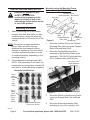
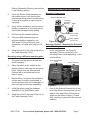
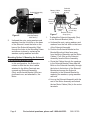
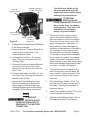
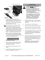
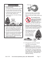
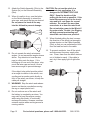
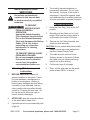
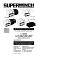
5,500 LB. CAPACITY 12 VOLT
WINCH WITH ROLLER FAIRLEAD
Model 91780
SET UP AND OPERATING INSTRUCTIONS
Visit our website at: http://www.harborfreight.com
Read this material before using this product.
Failure to do so can result in serious injury.
SAVE THIS MANUAL.
Copyright© 2004 by Harbor Freight Tools®. All rights reserved. No portion of this manual or any artwork
contained herein may be reproduced in any shape or form without the express written consent of
Harbor Freight Tools. Diagrams within this manual may not be drawn proportionally. Due to continuing
improvements, actual product may differ slightly from the product described herein. Tools required for
assembly and service may not be included.
For technical questions or replacement parts, please call 1-800-444-3353.
Manual Revised 10c
NOTICE is used to
address practices not
related to personal injury.
SAVE THIS MANUAL
Keep this manual for the safety warnings
and precautions, assembly, operating,
inspection, maintenance and cleaning
procedures. Write the product’s serial number
in the back of the manual near the assembly
diagram (or month and year of purchase if
product has no number). Keep this manual
and the receipt in a safe and dry place for
future reference.
CAUTION, without the
safety alert symbol, is
used to address practices not
related to personal injury.
WARNING Read all safety warnings
and instructions. Failure to follow the
warnings and instructions may result
in electric shock, fire and/or serious
injury.
Save all warnings and instructions
for future reference.
IMPORTANT SAFETY
INFORMATION
In this manual, on the labeling, and
all other information provided with
this product:
This is the safety alert
symbol. It is used to alert
you to potential personal
injury hazards. Obey all
safety messages that follow
this symbol to avoid possible
injury or death.
DANGER indicates a
hazardous situation
which, if not avoided, will result
in death or serious injury.
WARNING indicates a
hazardous situation
which, if not avoided, could
result in death or serious injury.
CAUTION, used with
the safety alert
symbol, indicates a hazardous
situation which, if not avoided,
could result in minor or moderate
injury.
Page 2
The warnings, precautions, and
instructions discussed in this
instruction manual cannot cover all
possible conditions and situations that
may occur. It must be understood
by the operator that common sense
and caution are factors which cannot
be built into this product, but must be
supplied by the operator.
INSTALLATION PRECAUTIONS
1.
Mounting location and hardware must
support winch and load.
2.
Wear ANSI-approved safety goggles
during installation, operation and service.
3.
Use supplied power cords and wire rope
listed in manual only. Do not use thinner/
longer cables or link multiple cables
together.
4.
Always connect the Red wire to the
positive battery terminal and the Black
wire to the negative battery terminal.
5.
Do not use a dirty, corroded or leaking
battery. You may suffer injury from acid
burns.
For technical questions, please call 1-800-444-3353.
SKU 91780
6.
Verify that the installation surface has no
hidden components or structural pieces
that will be damaged before drilling.
OPERATION PRECAUTIONS
1.
Do not exceed load capacity. Be aware
of dynamic loading! Sudden load
movement may briefly create excess
load causing product failure.
2.
Wear ANSI-approved safety goggles and
heavy-duty leather work gloves during
operation.
3.
Do not disengage clutch under load.
Engage clutch before starting.
4.
Keep clear of Fairlead when operating.
Do not try to guide wire rope.
5.
Place heavy rag or carpet
(not included) over wire
rope span 6 feet from
hook to help absorb
the force released if
the wire rope breaks.
6.
Stay out of the direct line that the wire
rope is pulling. In case it slips or breaks,
it will “whiplash” along this line.
7.
Do not winch a boat or other object with
anyone in or on it.
8.
Use a spotter to assist you in assuring
that it is safe to operate the winch.
Make sure the spotter is out of the way
of the vehicle and the wire rope before
activating the winch.
9.
10. Use as intended only. Do not lift items
vertically or use for aircraft purposes.
11. Prevent entanglement. Do not wear
loose clothing or jewelry, as they can
be caught in moving parts. Non-skid
footwear is recommended. Wear
restrictive hair covering to contain long
hair.
12. Inspect before every use; do not use if
damaged or if parts are loose. Examine
the winch for structural cracks, bends,
damage, frayed wire rope, and any
other condition that may affect the safe
operation of the winch. Do not use the
winch even if minor damage appears.
13. Keep children and bystanders away
while operating. Distractions can cause
you to lose control.
14. Stay alert, watch what you are doing
and use common sense when operating.
Do not use a winch while you are tired
or under the influence of drugs, alcohol
or medication. A moment of inattention
while operating winches may result in
serious personal injury.
15. Do not overreach. Keep proper footing
and balance at all times. This enables
better control of the winch in unexpected
situations.
16. People with pacemakers should
consult their physician(s) before use.
Electromagnetic fields in close proximity
to heart pacemaker could cause
pacemaker interference or pacemaker
failure.
17. Do not power the hook all the way into
the fairlead or winch.
Do not use the hand crank, if equipped,
to “assist” the winch.
SKU 91780
For technical questions, please call 1-800-444-3353.
Page 3
18.
Hook onto the object using
a pulling point, tow strap or
chain. Do not wrap the
wire rope around the
object and hook onto the
wire rope itself. This can cause damage
to the object being pulled, and kink or
fray the wire rope.
thinner/longer cables or link multiple
cables together.
3.
Have the winch serviced by a qualified
repair person using only identical
replacement parts. This will ensure that
the safety of the winch is maintained.
4.
Maintain labels and nameplates on the
winch. These carry important safety
information. If unreadable or missing,
contact Harbor Freight Tools for a
replacement.
5.
WARNING: Handling the cord on this
product will expose you to lead, a
chemical known to the State of California
to cause cancer, and birth defects or
other reproductive harm. Wash hands
after handling. (California Health &
Safety Code § 25249.5, et seq.)
19. Secure load after moving.
NO LOCKING MECHANISM.
20. Do not use a Recovery Strap while
winching. They are designed to stretch
and can suddenly whip back towards the
operator during a winching operation.
21. Keep at least 5 full turns of wire rope on
drum.
22. If wire rope begins to get entangled, stop
winch immediately and release wire rope
using switch.
15°
15°
SAVE THESE
INSTRUCTIONS.
45°
45°
23. Do not operate the winch at extreme
angles - do not exceed the angles shown
above.
SERVICE PRECAUTIONS
1.
Wear ANSI-approved safety goggles
during installation, operation and service.
2.
Use supplied power cords/wire rope or
cables listed in manual only. Do not use
Page 4
For technical questions, please call 1-800-444-3353.
SKU 91780
SPECIFICATIONS
Capacity
Motor
Power Supply
Schematics
5,500 lb. Single Line Pull on Layer 1
Permanent Magnet
3.4 HP
12 VDC
650 CCA or larger battery
Automatic Load
Yes
Holding Brake
3-Stage Planetary
Gear Train
294:1 Ratio
- 17.24” L x 6.3” W x 6.30” H without
Overall
Solenoid over motor
Dimensions
- 18.1” L x 6.30” W x 10.63” H with
Solenoid over motor
Drum Size
Ø2-1/2” Dia. x 5-1/2” W
Hook Opening 1/4”
Mounting Plate 6.54” x 4.5”
Mounting
6 Bolts (3w) M10 x 35 and Nuts M10
Hardware
Power Cords
60”, 5 Gauge (AWG)
Remote Cable 12’ cord
1/4” x 80’ Galvanized Steel
Wire Rope
7,000 lb. Nominal Strength
(7 x 19 Aircraft* type)
*“Aircraft” refers to the wire rope type, not the function
of the winch.
Performance of First Layer
Line Pull
(lb.)
0
2,000
3,000
4,000
5,500
Line Speed
(ft./min)
9.74
9.55
8.56
7.58
6.56
UNPACKING
When unpacking, make sure that the
item is intact and undamaged. If any parts
are missing or broken, please call Harbor
Freight Tools at 1-800-444-3353 as soon as
possible.
COMPONENTS
Amp
Draw
40
104
122
147
192
Motor
Cables
Solenoid
(17s & 24s)
(34w)
Line Pull and Wire Rope Capacity by
Layer
Wire Rope
Layer
1
2
3
4
5
Rated Line
Pull (lb.)
5500
4650
4000
3550
3180
Hook
Wire Rope
Capacity (ft.)
15
31.5
50
70
78.7
Note: If a winch is to be used to pull a
vehicle, it should optimally be rated to a
single line pull at least twice the vehicle’s
weight.
Winch
(Cable Assembly (36w))
Cam Ring (11)
Motor
Battery Cables
(13s & 16s)
Switch
Assembly
(35w)
Fairlead Mounting
Plate (45w)
Figure 1
Fairlead
(2w)
Mounting Hardware
Hook
Strap
(46w)
REV 10c
SKU 91780
For technical questions, please call 1-800-444-3353.
Page 5
INSTALLATION AND SETUP
Read the ENTIRE IMPORTANT
SAFETY INFORMATION
section at the beginning of this
manual including all text under
subheadings therein before set up
or use of this product.
Mounting the Winch
1.
Select a mounting site on the vehicle
bumper, truck bed, boat trailer, or other
suitable location, where the winch will
be perpendicular to the center line of the
vehicle.
NOTE: This winch can generate extreme
forces. Select a location that can
withstand the rated capacity without
damage or weakening. You may need to
use steel reinforcement plates, or weld
on additional bracing, depending on the
mounting location.
2.
Mounting using the Mounting Frame
(Sold separately - SKU 90476):
Mounting Frame
(Sold Separately - SKU 90476)
Bolt (47w)
Nut (6w)
Washer
(5w)
Flanged Nut
(44w)
Figure 2
Flanged Bolt
Fairlead Mounting
(43w)
Plate (45w)
Fairlead (2w)
1.
Mount the Fairlead (2w) to the Fairlead
Mounting Plate (45w) using two Flanged
Bolts (43w) and Nuts (44w).
2.
Mount the Fairlead/Mounting Plate
assembly to the Mounting Frame (sold
separately - SKU 90476) using two Bolts
(47w), Washers (5w) and Nuts (6w).
If the suggested mounting frame (SKU
90476 - sold separately) is not used, any
replacement mounting frame must be flat
and rated to at least the winch’s capacity.
Mounting Frame
(Sold Separately
SKU 90476)
Winch
Hardware Identification:
Use to
attach
Fairlead
(2w)
to
Plate
(45w)
Use to
attach
Plate
(45w) to
Frame
(SKU
90476)
Figure 3
Use to attach Winch to
Frame (SKU 90476)
Fairlead (2w)
3.
Mount the Winch to the Mounting Frame
using four Flanged Bolts (3w) and Nuts
(6w).
4.
Mount the Solenoid Assembly (34w)
according to one of the options in the
REV 10c
Page 6
For technical questions, please call 1-800-444-3353.
SKU 91780
Solenoid Assembly Mounting instructions
in the following section.
5.
Place the Electric Winch assembly at
the location where it will be mounted.
Use the remaining holes in the Mounting
Frame as a template to mark holes for
mounting.
6.
Verify that the installation surface has no
hidden components or structural pieces
that will be damaged before drilling.
7.
Drill holes at the marked locations.
8.
If the provided hardware does not
accommodate the installation, use
SAE grade 5 (Class 8.8) bolts (sold
separately), or higher, and torque to 35
ft-lb.
9.
Mounting the Solenoid Assembly
Mounting Components
Solenoid Bracket (14s)
Solenoid
Assembly
Motor
(34w)
Motor Cables
(17s & 24s)
Figure 4
Mounting Option 1: Mounting the Solenoid
to the Mounting Frame
Attach the Hook to the loop at the end of
the Cable Assembly (36w).
In this configuration, the Solenoid
Assembly (34w) is connected to the
Mounting Frame (sold separately), in line
with the Motor.
Mounting using a different mounting plate:
1.
2.
3.
The plate must be rated to at least the
winch’s capacity.
Solenoid Assembly
(34w)
Place the winch on the vehicle at the
desired location, and mark the mounting
holes. Decide how the Solenoid and
Fairlead will be mounted and mount
them in place.
Install the winch using the hardware
specified on the Specification chart.
5.
Attach the Hook to the loop at the end of
the Cable Assembly (36w).
SKU 91780
Motor Terminals
Motor
Cables
(17s & 24s)
Before drilling, verify that the installation
surface has no hidden components or
structural pieces that will be damaged or
that could cause structural weakening.
4.
Battery Cables
(13s & 16s)
Figure 5
1.
Line up the Solenoid Assembly with the
end of the Motor. Unthread one nut and
washer from each Motor Terminal and
attach the two Motor Cables (17s and
24s), securing in place with the nuts and
washers.
For technical questions, please call 1-800-444-3353.
Page 7
Battery Cables
(13s & 16s)
Solenoid Assembly
(34w)
Solenoid
Assembly
(34w)
Motor
Bracket
Mounting
Holes
Figure 6
2.
Mounting Frame
(Sold Separately SKU 90476)
Unthread the nuts, spring washers and
washers from the four bolts on the base
of the Solenoid. Insert the bolts on the
base of the Solenoid Assembly (34w)
through the holes in the Mounting Frame
and secure in place by replacing the
washers, spring washers and nuts.
Mounting Option 2: Mounting the Solenoid
to the Solenoid Bracket (40w)
In this configuration, the Solenoid is
rotated so that the two short cables
attached to the Motor Terminals are
crossed and Solenoid Assembly
(34w) and Solenoid Bracket (40w) are
positioned over, and attached to, the
Motor.
Figure
1.
Solenoid
Motor Cables
Bracket
(17s & 24s)
(40w)
Bracket Tie-down
Strap (41w)
7
To attach the Solenoid Assembly (34w)
to the Solenoid Bracket (40w):
a.Unthread the nuts, spring washers and
washers from the four bolts on the base
of the Solenoid Assembly.
b.Position the Solenoid Bracket so the
Bracket Mounting Holes face away
from the Motor Assembly and the Motor
Cables (17s & 24s) on the Solenoid
Assembly face the Motor Assembly.
c.Route the Cables through the openings
in the Solenoid Bracket, then slide the
Bolts on the Solenoid Assembly through
the holes in the bottom of the Solenoid
Bracket and secure the Solenoid
Assembly to the Solenoid Bracket by
replacing the washers, spring washers
and nuts.
d.Line up the Solenoid Assembly with the
end of the Motor Assembly and attach
the two Motor Cables (24s) to the motor
terminals.
Page 8
For technical questions, please call 1-800-444-3353.
SKU 91780
Turn the Power Switch of the
winch off and disconnect the
power and control cables before
making wiring connections.
Bracket mounted to
Tie Bar (10w) ends
Solenoid
Assembly (34w)
TO PREVENT
SERIOUS INJURY
FROM LEAKING BATTERY ACID:
Do not use a dirty, corroded or
leaking battery. Only use a 12V
automotive (or equivalent)
battery, in good condition.
Motor Cables
(17s & 24s)
Motor
Figure 8
2.
1.
Plan a route for the wiring from the
point of the vehicle where the winch
will be mounted or used to the battery.
This route must be secure, out of the
way of moving parts, road debris, or
any possibility of being damaged by
operation or maintenance of the vehicle.
For example, you may wish to route
the wires under the vehicle, attaching
it to the frame using suitable fasteners.
Do not attach the wires to the exhaust
system, drive shaft, emergency brake
cable, fuel line, or any other components
which may damage wiring through heat
or motion, or create a fire hazard.
2.
If you drill through the bumper or any
part of the body to route the wires, be
sure to install a rubber grommet in the
hole to prevent fraying of the wires at
that point.
3.
Route the Battery Cables (13s & 16s)
from the point the winch will be used to
the battery, following the precautions
discussed above.
4.
Attach the red Battery Cable (13s) to the
positive terminal on the battery.
5.
Attach the black Battery Cable (16s) to
the negative terminal of the battery.
Bracket
Tie-down
Strap (41w)
To attach the Solenoid Assembly/Bracket
to the Motor Assembly:
a.Slide the Bracket Tie-down Strap (41w)
over the hook in the center of the
Solenoid Bracket (40w).
b.Unthread the two Bolts (12-1w) and
Nuts (13w) from the motor end of the
Tie Bars (10w).
c.Rotate the Solenoid Assembly/Bracket
so that the holes on the side of the
Bracket line up with the end of the Tie
Bars (10w).
d.Re-insert and tighten the Bolts (12-1w)
and Nuts (13w), securing the Solenoid
Bracket to the Tie Bar.
e.Secure the Solenoid Bracket to the
Motor by tightening the Bracket Tie
Down Strap (41w) around both the
Solenoid Bracket hook and the Motor
Assembly. Pull the Strap until secure.
Wiring
TO PREVENT
SERIOUS INJURY
FROM EXPLOSION DUE TO
SPARKING AT THE BATTERY
CONNECTION:
SKU 91780
For technical questions, please call 1-800-444-3353.
Page 9
OPERATION
Solenoid Assembly (34w)
Read the ENTIRE IMPORTANT
SAFETY INFORMATION
section at the beginning of this
manual including all text under
subheadings therein before set up
or use of this product.
The instructions that follow are
basic guidelines only and cannot
cover all situations encountered
during use. The operator and
assistants must carefully plan
usage to prevent accidents.
Socket (6s)
Switch
Assembly
(35w)
Socket Cover (2s)
Figure 9
6.
Lift the Socket Cover (2s) on the
Solenoid Assembly (34w) and insert the
Switch Assembly (35w) connector into
the Socket (6s). Disconnect the Switch
Assembly when not in use.
Note: The attachment of the Motor Cables
(17s & 24s) determines the way the
toggle button on the Switch Assembly
(35w) operates. After the unit is mounted
and powered, check the direction of the
Power In and Power Out on the Switch
button. To change the direction on the
Switch, disconnect the Battery Cables
from the battery, switch the Motor Cable
connections on the Motor terminal, then
reconnect the Battery Cables.
Preparing the Wire Rope
BEFORE FIRST USE:
1.
The wire rope must be properly coiled
under tension to be able to support a
load without damage.
2.
Uncoil the wire rope, except for 5 full
wraps.
3.
Recoil the wire rope back into the winch
under at least 500 lb. of tension.
Page 10
1.
Examine the wire rope. Do not use the
winch if the wire rope is frayed, kinked or
damaged.
2.
Fully charge the vehicle’s battery.
3.
Check the winch’s electrical connections.
All connections must be tight and clean.
4.
Put the vehicle’s transmission in Neutral.
5.
If the vehicle where the winch is mounted
is not supposed to move, engage the
emergency brake and block the wheels
using wheel chocks.
6.
To pull out the wire rope, move the Cam
Ring (11w) to the OUT position, slide the
loop of the Hook Strap (46w) over the
hook, then pull on the Hook Strap to pull
out the wire rope.
WARNING! Leave at least five full
turns of wire rope on the drum.
For technical questions, please call 1-800-444-3353.
SKU 91780
Safety Clasp
Double Line Rigging:
a.A double line system should be used
whenever possible.
It reduces the load on the winch, allowing
it to work longer with less heat buildup.
It reduces load on the winch in two ways:
• it utilizes the lower layers of wire rope
that have higher capacity, and
7.
Hook onto the object using a pulling
point, tow strap, tree strap, or chain.
Make sure the hook’s safety clasp is fully
closed.
Do not wrap the wire
rope around the object
and hook onto the wire
rope itself. This can
damage the object being
pulled, and kink or fray the wire rope.
8.
Do not use a Recovery Strap while
winching. They are designed to stretch
and can suddenly whip back towards the
operator during a winching operation.
9.
Place heavy rag or carpet
(not included) over wire
rope span 6 feet from
hook to help absorb
the force released if
the wire rope breaks.
• it halves the load on the winch through
pulley action.
Stationary
Winching
Vehicle
(Chock tires, and
set parking brake)
Carpet
Load
b.Connect the wire rope for a double line
system as shown above. Use a pulley
block (not included) properly rated for
the load to be pulled and designed to be
operated with this winch’s wire rope.
c.Loop the wire rope around the pulley and
connect to another part of the vehicle’s
chassis or to a separate anchor point.
Do not anchor the cable back to the
winch or winch mount.
10. Re-engage the clutch by moving the
Cam Ring to the IN position.
11. WARNING! Do not allow anyone to
stand near the wire rope, or in line with
the wire rope behind the winch while it
is under power. If the wire rope should
slip or break, it can suddenly whip back
towards the winch, causing a hazard for
anyone in the area. Stand well to the
side while winching.
SKU 91780
For technical questions, please call 1-800-444-3353.
Page 11
12. Attach the Switch Assembly (35w) to the
Socket (6s) on the Solenoid Assembly
(34w).
13. When it is safe to do so, use the button
on the Switch Assembly to retract the
wire rope, and winch the item as desired.
Do not power the hook all the way
into the fairlead to prevent damage.
15°
15°
45°
45°
14. Do not operate the winch at extreme
angles - do not exceed the angles shown
above. Pay attention to how the wire
rope is coiling onto the drum. If it is
building up on one end of the drum, stop,
uncoil the wire rope and recoil it from a
less severe angle to prevent damage.
CAUTION Do not use the winch in a
constant duty application, it is
designed for INTERMITTENT USE
ONLY. Keep the duration of the
pulling job as short as possible. If the
motor becomes very hot to the touch,
stop and let it cool down for several
minutes. Do not pull for more than
one minute at or near the rated load.
Do not maintain power to the Winch if
the motor stalls. Double Line Rigging
will help prevent overloading and
should be used whenever practical.
17. When finished pulling the load, reverse
the direction of the winch just enough to
release tension on the Cable Assembly
(36w) so that you can unfasten the Hook
from the load and reel in the cable.
18. To prevent accidents, turn off the winch
and disconnect its power supply after
use. Clean, then store the winch indoors
out of children’s reach. If the cable is
wet, dry it then apply light oil right after
use.
If the object to be pulled must be pulled
at an angle in relation to the winch, use
a pulley and an anchor point directly in
front of the winch, as shown, to keep the
cable pull straight.
15. WARNING! Stop the winch and release
tension on the wire rope before moving
the rag or carpet placed on it.
16. Do not continue use of the winch until
the battery is completely run down. You
may wish to keep the engine running
while using this winch, to continually
recharge the battery. However, exercise
extreme caution when working around a
running vehicle.
Page 12
For technical questions, please call 1-800-444-3353.
SKU 91780
MAINTENANCE AND
SERVICING
4.
Procedures not specifically
explained in this manual must
be performed only by a qualified
technician.
TO PREVENT
SERIOUS INJURY
FROM ACCIDENTAL
OPERATION:
Unplug the Switch Assembly
(35w) connector from the Socket
(6s) on the Solenoid Assembly
(34w) and disconnect the Battery
Cables (13s & 16s) before
performing any inspection,
maintenance, or cleaning
procedures.
TO PREVENT SERIOUS INJURY
FROM WINCH FAILURE:
Do not use damaged equipment.
If abnormal noise or vibration
occurs, have the problem
corrected before further use.
Cleaning, Maintenance, and
Lubrication
1.
BEFORE EACH USE, inspect the
general condition of the winch. Check
for loose hardware, misalignment or
binding of moving parts, cracked or
broken parts, damaged electrical wiring,
corroded or loose terminals, and any
other condition that may affect its safe
operation. Examine the wire rope. Do
not use the winch if the wire rope is
frayed, kinked or damaged.
2.
AFTER USE, wipe the external surfaces
of the winch with a clean cloth.
3.
Lubricate the wire rope occasionally with
a light oil.
SKU 91780
The winch’s internal mechanism is
permanently lubricated. Do not open
the housing. However, if the winch is
submerged, it should be opened, dried,
and relubricated by a qualified technician
as soon as possible to prevent corrosion.
Cable Replacement
1.
Move the Cam Ring (11w) to the OUT
position.
2.
Manually pull the Cable out to it’s full
length. Note how the existing cable is
connected to the inside of the drum.
3.
Remove the old Cable Assembly and
attach the new assembly.
CAUTION: Do not replace with inferior cable.
Always use an approved replacement
part from Harbor Freight Tools.
4.
The cable must be rewound in the
direction shown on the winch. Retract
the Cable onto the cable drum being
careful not to allow kinking.
5.
Coil the wire rope 5 full wraps.
6.
Then, coil the wire rope into the winch
under at least 500 lb. of tension.
For technical questions, please call 1-800-444-3353.
Page 13
Troubleshooting
Problem
Motor does not turn
on.
Possible Causes
1. Switch not connected properly.
2. Loose power cord connections.
3. Battery needs charging.
4. Solenoid malfunctioning.
5. Defective Switch.
6. Defective motor.
7. Water has entered motor.
8. Internal damage or wear.
Motor runs but cable Clutch not engaged.
drum does not turn.
Motor runs slowly
or without normal
power.
Motor runs in one
direction only.
Motor overheats.
1. Insufficient current or voltage.
2. Loose or corroded battery cable
connections.
3. Incorrect power cords.
1. Defective or Stuck solenoid.
2. Defective Switch Assembly.
1. Incorrect power cords.
2. Winch running time too long.
Likely Solutions
1. Connect Switch properly.
2. Tighten all connections.
3. Fully charge battery.
4. Tap solenoid to loosen contacts. Briefly
apply 12 volts directly to coil terminals.
Clicking indicates proper activation.
5. Replace Switch.
6. Check for voltage at armature port with
Switch pressed. If voltage is present, replace
motor.
7. Allow to drain and dry. Run in short bursts
without load until completely dry.
8. Have technician service winch.
Move the Cam Ring to the In position. If
problem persists, a qualified technician needs
to check and repair.
1. Battery weak, recharge. Run winch with
vehicle engine running.
2. Clean, tighten, or replace.
3. Use only supplied power cords.
1. Tap Solenoid to loosen contacts. Repair or
replace solenoid.
2. Replace Switch Assembly.
1. Use only supplied power cords.
2. Allow winch to cool down periodically.
Follow all safety precautions whenever diagnosing or servicing the winch.
Disconnect power supply before service.
PLEASE READ THE FOLLOWING CAREFULLY
THE MANUFACTURER AND/OR DISTRIBUTOR HAS PROVIDED THE PARTS LIST AND ASSEMBLY
DIAGRAM IN THIS MANUAL AS A REFERENCE TOOL ONLY. NEITHER THE MANUFACTURER OR
DISTRIBUTOR MAKES ANY REPRESENTATION OR WARRANTY OF ANY KIND TO THE BUYER THAT HE
OR SHE IS QUALIFIED TO MAKE ANY REPAIRS TO THE PRODUCT, OR THAT HE OR SHE IS QUALIFIED
TO REPLACE ANY PARTS OF THE PRODUCT. IN FACT, THE MANUFACTURER AND/OR DISTRIBUTOR
EXPRESSLY STATES THAT ALL REPAIRS AND PARTS REPLACEMENTS SHOULD BE UNDERTAKEN BY
CERTIFIED AND LICENSED TECHNICIANS, AND NOT BY THE BUYER. THE BUYER ASSUMES ALL RISK
AND LIABILITY ARISING OUT OF HIS OR HER REPAIRS TO THE ORIGINAL PRODUCT OR REPLACEMENT
PARTS THERETO, OR ARISING OUT OF HIS OR HER INSTALLATION OF REPLACEMENT PARTS THERETO.
Page 14
For technical questions, please call 1-800-444-3353.
SKU 91780
WINCH PARTS LIST & ASSEMBLY DIAGRAM
Part
2w
3w
5w
6w
7w
8w
9w
10w
11w
12w
13w
14w
15w
16w
17w
18w
20w
21w
22w
23w
24w
25w
Description
Fairlead
Bolt M10 x 34
Washer M10
Nut M10
End Bearing
Spring
Locking Ring
Tie Bar
Cam Ring
Bolt M8 x 30
Nut M8
Gear Ring
Gear Retainer Ring
Half Ring
Bolt M6 x 20
Gear - Output
Roll Pin Ø4 x 10
Cable Anchor
Bolt M6 x 12
Gear (Intermediate)
Gear (Input)
Thrust Disc
Qty
1
4
2
6
1
6
1
2
1
4
4
1
1
2
6
1
1
1
1
1
1
1
Part
26w
27w
28w
29w
30w
31w
32w
33w
34w
35w
36w
37w
38w
39w
40w
41w
42w
43w
44w
45w
46w
47w
Description
Thrust Washer
Bushing-Drum
Gasket
Cover Gear Housing
Screw M5 x 12
Drum
Break / Shaft Assembly
Motor End Bearing Assembly
Solenoid Assembly
Switch Assembly
Cable Assembly 80’ L x 1/4” D
Gear Carrier Assembly - Output
Gear Carrier Assembly - Intermediate
Gear Carrier Assembly - Input
Solenoid Bracket
Bracket Tie-Down Strap
Spring Washer 5 mm
Bolt M12 x 25
Nut M12
Fairlead Mounting Plate
Hook Strap
Bolt M10 x 34 (none standard)
Qty
3
2
1
1
6
1
1
1
1
1
1
1
1
1
1
1
6
2
2
1
1
2
Note: When ordering parts for Winch, include the suffix “w” after the part number.
5
REV 10c
SKU 91780
For technical questions, please call 1-800-444-3353.
Page 15
SOLENOID PARTS LIST & ASSEMBLY DIAGRAM
Part
1s
2s
3s
4s
5s
6s
7s
8s
9s
10s
11s
12s
Description
Plastic Housing
Socket Cover
Flat Washer
Spring Washer
Screw M5 x 10
Socket
Screw M5 x 12
Copper Spacer
Screw M5 x 12
Solenoid
Ground Cable
Screw M6 x 30
Qty
1
1
6
4
4
1
2
1
2
1
1
4
Part
13s
14s
15s
16s
17s
18s
19s
20s
21s
22s
23s
24s
Description
Battery Cable (red) (+)
Solenoid Bracket
Nut M8
Battery Cable (Black) (-)
Motor Cable (Black) (-)
Nut M5
Spacer
Flat Washer
Spring Washer
Nut M6
Fiberglass Sleeve
Motor Cable (Black) (+)
Qty
1
1
4
1
1
1
3
8
8
8
1
1
REV 10c
Page 16
For technical questions, please call 1-800-444-3353.
SKU 91780
ROLLER FAIRLEAD PARTS LIST & ASSEMBLY DIAGRAM
Part
1f
2f
3f
4f
Description
Cap Nut
Lock Washer
Short Shaft
Nylon Bushing
Qty
8
8
2
8
Part
5f
6f
7f
8f
Description
Short Roller (Ø 3-3/8: x 1-3/8”
Long Shaft
Long Roller (Ø 4-3/4” x 1-3/8”)
Base
Qty
2
2
2
1
Record Product’s Serial Number Here:
Note: If product has no serial number, record month and year of purchase instead.
Note: Some parts are listed and shown for illustration purposes only, and are not available
individually as replacement parts.
SKU 91780
For technical questions, please call 1-800-444-3353.
Page 17
90 Day Warranty
Harbor Freight Tools Co. makes every effort to assure that its products meet high quality
and durability standards, and warrants to the original purchaser that this product is free from
defects in materials and workmanship for the period of 90 days from the date of purchase. This
warranty does not apply to damage due directly or indirectly, to misuse, abuse, negligence or
accidents, repairs or alterations outside our facilities, criminal activity, improper installation,
normal wear and tear, or to lack of maintenance. We shall in no event be liable for death,
injuries to persons or property, or for incidental, contingent, special or consequential damages
arising from the use of our product. Some states do not allow the exclusion or limitation of
incidental or consequential damages, so the above limitation of exclusion may not apply to
you. THIS WARRANTY IS EXPRESSLY IN LIEU OF ALL OTHER WARRANTIES, EXPRESS
OR IMPLIED, INCLUDING THE WARRANTIES OF MERCHANTABILITY AND FITNESS.
To take advantage of this warranty, the product or part must be returned to us with
transportation charges prepaid. Proof of purchase date and an explanation of the complaint
must accompany the merchandise. If our inspection verifies the defect, we will either repair or
replace the product at our election or we may elect to refund the purchase price if we cannot
readily and quickly provide you with a replacement. We will return repaired products at our
expense, but if we determine there is no defect, or that the defect resulted from causes not
within the scope of our warranty, then you must bear the cost of returning the product.
This warranty gives you specific legal rights and you may also have other rights which vary
from state to state.
3491 Mission Oaks Blvd. • PO Box 6009 • Camarillo, CA 93011 • (800) 444-3353
Page 18
For technical questions, please call 1-800-444-3353.
SKU 91780