1
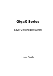
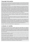
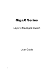
English
GigaX 1124
Quick Installation Guide
Copyright © 2004 ASUSTeK COMPUTER INC. All Rights Reserved.
Introduction
English
The GigaX 1124 rack-mountable switch provides non-blocking, wire-speed
performance to meet your intensive network demands. The switch features
MDI/MDIX Ethernet ports with auto-sensing capability to automatically
detect the cables attached to them and adjust the speed of data
exchange. This plug-and-play function requires no configuration, making
the switch easy to install and maintain.
The switch also manages congestion and prioritizes traffic with flow control
schemes and Quality of Service (QoS) ability, thus enhancing your
network’s efficiency.
Features
• (24) 10/100/1000 Mbps RJ-45 ports
• Plug and play – automatic MDI/MDIX and auto-sensing for speed and
duplex mode on all ports
• Surface or rackmount placement options
• Flow control schemes (802.3x in full-duplex mode) to support zero loss
under temporary network congestion
• Backpressure support for 10/100 Mbps half duplex
• Advanced QoS support
• 4K Media Access Control (MAC) addressing with learning and aging
feature that allows concurrent connections to 4K nodes
• Up to 2 Gbps for all ports in full-duplex mode
• Easy-to-read LEDs for quick indication of link status, activities, speed and
duplex mode on all ports
• Built-in Virtual Cable Tester (VCT) feature
• 10KB jumbo frame support
Package contents
Before installing the switch, check your package for the following items:
•
•
•
•
GigaX 1124 switch
Power cable
Mounting kit (two brackets and six screws)
Quick installation guide
NOTE. Contact your retailer if any item is damaged or missing.
2
ASUS GigaX 1124
Technical specifications
Technical Specifications
Physical dimensions
43.5mm (H) X 444 mm (W) X 200mm (D)
Environmental ranges
Power
English
Table 1
Operating
Storage
Temperature
0º to 40º C
(32º to 104º F)
-40º to 70º C
(-40º to 158º F)
Humidity
0 to 85%
0 to 90%
Altitude
up to 15,000 ft
(4,500 m)
up to 40,000 ft
(12,000 m)
Input
100V ~ 240 V AC/50-60 Hz
Consumption 50 Watts
Certification
ASUS GigaX 1124
FCC Class A, CE, C-TICK, UL, CB
3
Front Panel
English
4
1 2
5 6 7
3
Table 1
Buttons
BUTTON
Function
1
VCT
Start, execute, or exit VCT
2
SEL
Select the port to execute VCT
Table 2
LED
3
SYSTEM
LED indications during normal operation
Color
Status
Description
Green
Red
On
On
The switch is on and in normal operation.
The switch is initializing or VCT is in
progress.
The switch is off.
Off
4
4
1 – 24
5
STATUS
Green
On
Blinking
Off
Ethernet link is established.
Receiving or transmitting data
No Ethernet link
6
SPEED
Green
Amber
On
On
Off
1000 Mbps
100 Mbps
10 Mbps or no Ethernet link
7
DUPLEX
Green
Amber
On
On
Off
The switch is operating in full-duplex mode.
The switch is operating in half-duplex mode.
No Ethernet link
Port numbers
ASUS GigaX 1124
3
LED indications in VCT mode
LED
Color
Status Description
SYSTEM
Green
Red
On
On
Off
English
Table 3
The switch is on.
The switch is initializing or VCT is in
progress.
The switch is off.
4
1 – 24
5
STATUS
Green
(Port Select)
On
The port is selected to execute VCT.
Blinking VCT on the port is in progress.
Off
The port is not selected.
6
SPEED
(Pairs 1, 3)
Green
Amber
On
On
7
DUPLEX
(Pairs 2, 4)
Green
Amber
On
On
Port numbers
The pair is shorted.
The pair is open (the cable is not attached
to any device).
Blinking The port failed to execute VCT.
Off
VCT is in progress (PORT SELECT LED
is blinking)
OR
No error is found (PORT SELECT LED
is green)
The pair is shorted.
The pair is open (the cable is not attached
to any device).
Blinking The port failed to execute VCT.
Off
VCT is in progress (PORT SELECT LED
is blinking).
OR
No error is found (PORT SELECT LED
is green).
NOTE. The number of lighted LEDs on Pairs 1 ~ 4 shows the distance
from the switch to the defective point (1 LED = 10 meters).
ASUS GigaX 1124
5
Rear Panel
English
Power connector
Fans
Connecting network devices
To connect network devices to the switch:
1. Connect one end of an Ethernet cable to an Ethernet port on the front
panel of the switch. Connect the other end to the Ethernet port of the
network device. Repeat this step to connect other network devices.
NOTES
•
Use only Category 5 Ethernet cables to ensure proper connections
between the switch and other network devices.
•
You may use the ports on the switch to uplink to another switch,
hub, bridge, or repeater as an uplink port using either crossover or
straight-through cables.
The MDI/MDIX feature of the switch allows automatic detection of
the type of cables connected to it, and adjustment to the
appropriate MDI or MDIX setting for each cable.
2. Plug one end of the power cable to the power connector on the switch
rear panel, then plug the other end to an electrical outlet.
The Power LED and the LED indicators for active Ethernet ports light up
to indicate that the device is on and in use. Refer to the front panel LED
table on page 4 for the LED descriptions.
6
ASUS GigaX 1124
Virtual Cable Tester (VCT)
English
The VCT feature significantly reduces networking and support costs by
virtually diagnosing and reporting cable faults using the Time Domain
Reflectometry (TDR) technology. With VCT, you can identify open and
shorted cables with up to 10 meters of accuracy.
Using the VCT feature
To do a cable test using VCT:
1. Press the VCT button once.
The switch goes into VCT mode and the system LED turns amber. All
port LEDs are off, except the PORT SELECT (STATUS) LED.
2. Press the SEL button to select the port you wish to test. The PORT
SELECT (STATUS) LED of the selected port lights up.
NOTE. If no other action is taken after the VCT or SEL button is
pressed, the switch automatically goes back to normal operation after
15 seconds.
3. Press the VCT button again to execute VCT on the selected port. The
PORT SELECT (STATUS) LED of the selected port blinks in green to
indicate that VCT is in progress.
The test is complete when the PORT SELECT (STATUS) LED stops
blinking. Refer to page 9 for examples of VCT test results.
4. Press SEL to select another port to test. Follow steps 2 to 5 to run VCT.
5. When done, press the VCT button to return to normal switch operation.
NOTE. The switch automatically goes back to normal operation after
two minutes even if you do not press the VCT button.
ASUS GigaX 1124
7
English
VCT test results
The cable is not connected to any device
LED
PORT
SELECT
Pair 1
Pair 2
Pair 3
Pair 4
COLOR
Green
Amber
Amber
Amber
Amber
DESCRIPTION
The cable is OK.
The four pairs in
this cable are open
(not connected)
up to at least
80 meters.
Port Select
GRN
AMB
AMB
AMB
AMB
AMB
AMB
AMB
AMB
AMB
AMB
AMB
AMB
AMB
AMB
AMB
AMB
AMB
AMB
AMB
AMB
AMB
AMB
AMB
AMB
Pair 1
Pair 2
Port Select
GRN (Green)
AMB
AMB
AMB
AMB
AMB
AMB
AMB
AMB
AMB
AMB
AMB
AMB
Pair 3
AMB
AMB
AMB
AMB
AMB
AMB
AMB
AMB
AMB
AMB
AMB
AMB
Pair 4
10m
20m
30m
40m
50m
60m
70m
80m
90m
100m
110m
120m
AMB (Amber)
G - Green
A - Amber
The cable is connected to a Fast Ethernet (10/100 Mbps) device
LED
COLOR
PORT
SELECT
Pair 1
Pair 2
Pair 3
Green
DESCRIPTION
Port Select
GRN
Pair 1
Pair 4
Off
Off
Green
or Amber
Green
or Amber
Pairs 1 and 2 are
connected to a
device.
Pair 2
Port Select
GRN (Green)
GRN
GRN
GRN
GRN
GRN
GRN
GRN
GRN
GRN
GRN
GRN
GRN
Pair 3
AMB
AMB
AMB
AMB
AMB
AMB
AMB
AMB
AMB
AMB
AMB
AMB
Pair 4
10m
20m
30m
40m
50m
60m
70m
80m
90m
100m
110m
120m
AMB (Amber)
G - Green
A - Amber
NOTE. Fast Ethernet (10/100 Mbps) uses only two pairs (Pairs 1 and
2) of cables to transmit/receive data. Disregard Pairs 3 and 4 LEDs.
The cable is connected to a Gigabit (1000 Mbps) device
LED
COLOR
PORT
SELECT
Pair 1
Pair 2
Pair 3
Pair 4
Green
DESCRIPTION
Port Select
GRN
Pair 1
Off
Off
Off
Off
Four pairs are
connected to a
device.
Pair 2
Port Select
Pair 3
Pair 4
10m
GRN (Green)
20m
30m
40m
50m
G - Green
8
60m
70m
80m
90m
100m
110m
120m
AMB (Amber)
A - Amber
ASUS GigaX 1124
Placement options
English
Placing the switch on a flat surface
Place the switch on a flat surface that can support the weight of the switch
and its accessories. Make sure the surface meets the operating
environment specifications.
NOTE. The length of the UTP Category 5 cable should not exceed 80
meters.
Mounting the switch on a rack
To mount the switch on a rack:
1.
2.
3.
4.
5.
Locate the screw holes on each side of the switch.
Align a mounting bracket with the screw holes on one side of the switch.
Secure the mounting bracket using three screws.
Follow steps 2 and 3 to secure the other bracket.
Place the switch on a 19-inch rack, then secure it with two rack mount
screws.
NOTE. The rack mount screws are not included in your switch
package. Use the screws from the rack.
ASUS GigaX 1124
9
Troubleshooting
English
This troubleshooting guide provides answers to some common problems
that you may encounter while installing and/or using the switch. These
problems require some simple troubleshooting that you can perform by
yourself. Contact ASUS Technical Support if you encounter problems that
are not mentioned in this section.
Problem
10
Action
The POWER LED does not
light up.
Check if the power cable is properly
connected to the switch, and to an
electrical outlet with the correct
voltage output. See the power
specifications on page 3.
The STATUS/SPEED LED
does not light up even after
an Ethernet cable is
connected.
• Check if the Ethernet cable is
properly connected to the switch
and to the network device.
• Make sure that the switch and
your network device are turned
on.
• Check if the Ethernet cable is
sufficient for your network speed.
Make sure you are using at least
Category 5 cables for 100/1000
Mbps. If the network speed is 10
Mbps, you may use Category 3
cables.
ASUS GigaX 1124