1
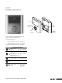
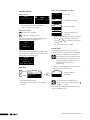
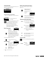
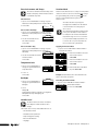
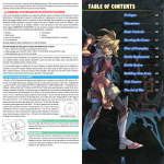
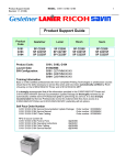
R A D I A N T H E AT I N G A N D
COOLING SYSTEMS
˘NTROL™
C L I M AT E C O
ZONING SYSTEM
INSTALLATION GUIDE
Climate Co˘ntrol™ Zoning System
Installation Guide
Uponor Climate Co˘ntrol
Zoning System Installation Guide
Published by Uponor, Inc.
5925 148th Street West
Apple Valley, MN 55124 USA
Phone: (800) 321-4739
Fax: (952) 891-2008
www.uponor-usa.com
© 2010 Uponor
All Rights Reserved.
First Edition
First Printing May 2008
Printed in the United States of America
2
www.uponor-usa.com • www.uponor.ca
Note: This equipment has been tested and found
to comply with the limits for a Class B digital device,
pursuant to part 15 of the FCC Rules. These limits are
designed to provide reasonable protection against
harmful interference in a residential installation.
This equipment generates, uses and can radiate radio
frequency energy and, if not installed and used in
accordance with the instructions, may cause harmful
interference to radio communications. However, there
is no guarantee that interference will not occur in a
particular installation. If this equipment does cause
harmful interference to radio or television reception,
which can be determined by turning the equipment
off and on, the user is encouraged to try to correct the
interference by one or more of the following measures:
• Reorient or relocate the receiving antenna
• Increase the separation between the equipment
and receiver
• Connect the equipment into an outlet on a
circuit different from that to which the receiver is
connected
• Consult the dealer or an experienced radio/TV
technician for help
Operation is subject to the following two conditions:
(1) this device may not cause interference, and (2)
this device must accept any interference, including
interference that may cause undesired operation of
the device.
Uponor Climate Co˘ntrol™ Zoning System Installation Guide
i
ii
www.uponor-usa.com • www.uponor.ca
Table of Contents
The Uponor Climate Co˘ntrol Zoning
System Installation Guide
Section 1: General Recommendations. . . . . . . . . . . . . . . 1
Safety Measures . . . . . . . . . . . . . . . . . . . . . . . . . . 1
Symbols Used in This Manual . . . . . . . . . . . . . . . . . . . . . 1
Power Supply . . . . . . . . . . . . . . . . . . . . . . . . . . . 1
Limitations for Radio Waves . . . . . . . . . . . . . . . . . . . . . . 1
Technical Constraints . . . . . . . . . . . . . . . . . . . . . . . . 1
Section 2: The Uponor Climate Co˘ntrol Zoning
System Overview. . . . . . . . . . . . . . . . . . . . . . . . . . . . . . . 3
Thermostat Display T-75 . . . . . . . . . . . . . . . . . . . . . . . 3
Base Unit With Antenna and Actuators . . . . . . . . . . . . . . . . . 3
Interface I-75 . . . . . . . . . . . . . . . . . . . . . . . . . . . 3
Uponor Climate Co˘ntrol Zoning System Components . . . . . . . . . . . . 4
Section 3: Base Unit Installation. . . . . . . . . . . . . . . . . . . 5
Base Unit Diagram . . . . . . . . . . . . . . . . . . . . . . . . . 5
Preparation Before Installation . . . . . . . . . . . . . . . . . . . . . 5
Components Installation . . . . . . . . . . . . . . . . . . . . . . . 6
Section 4: Thermostat Installation. . . . . . . . . . . . . . . . . 11
Label the Room Thermostats . . . . . . . . . . . . . . . . . . . . .
Register Room Thermostats . . . . . . . . . . . . . . . . . . . . . Determining the Thermostat Location . . . . . . . . . . . . . . . . . Mounting the Thermostat . . . . . . . . . . . . . . . . . . . . . .
11
12
13
13
Section 5: Thermostat and Base Unit Testing. . . . . . . . 15
Testing the Communication Between Thermostats and Base Unit . . . . . . . 15
Testing the Base Unit Actuator . . . . . . . . . . . . . . . . . . . . 16
Final Inspection . . . . . . . . . . . . . . . . . . . . . . . . . . 16
Section 6: Interface with Base Unit Installation. . . . . . 17
Example of an Installation . . . . . . . . . . . . . . . . . . . . . .
Interface Bracket Installation . . . . . . . . . . . . . . . . . . . . .
Wiring and Programming the Interface . . . . . . . . . . . . . . . . .
Connections . . . . . . . . . . . . . . . . . . . . . . . . . . . Time and Date Setup . . . . . . . . . . . . . . . . . . . . . . . .
Attaching the Interface to Bracket . . . . . . . . . . . . . . . . . . .
Interface Setup . . . . . . . . . . . . . . . . . . . . . . . . . .
Installation Inspection . . . . . . . . . . . . . . . . . . . . . . . Alarms . . . . . . . . . . . . . . . . . . . . . . . . . . . . . Resetting the Interface . . . . . . . . . . . . . . . . . . . . . . .
Uponor Climate Co˘ntrol™ Zoning System Installation Guide
17
18
19
20
22
23
23
24
24
24
iii
Table of Contents (continued)
Section 7: Thermostat Operation. . . . . . . . . . . . . . . . . . 25
Thermostat T-75 Display . . . . . . . . . . . . . . . . . . . . . . Changing the Temperature Format . . . . . . . . . . . . . . . . . . .
Changing the Temperature Setpoint . . . . . . . . . . . . . . . . . . Setting the Minimum and Maximum Temperatures . . . . . . . . . . . . Thermostat Battery Replacement . . . . . . . . . . . . . . . . . . . 25
25
25
26
26
Section 8: Interface Operation. . . . . . . . . . . . . . . . . . . . 27
Interface Screens . . . . . . . . . . . . . . . . . . . . . . . . . Access Level . . . . . . . . . . . . . . . . . . . . . . . . . . . Information Menu . . . . . . . . . . . . . . . . . . . . . . . . .
Room Temperature . . . . . . . . . . . . . . . . . . . . . . . . ECO (Economy) . . . . . . . . . . . . . . . . . . . . . . . . . .
Battery and Communication Status . . . . . . . . . . . . . . . . . . Thermostat and Actuator Status . . . . . . . . . . . . . . . . . . . Actuator Status . . . . . . . . . . . . . . . . . . . . . . . . . .
Settings menu . . . . . . . . . . . . . . . . . . . . . . . . . . Information Menu: System Information . . . . . . . . . . . . . . . . .
ECO Mode . . . . . . . . . . . . . . . . . . . . . . . . . . . .
Steps to Follow . . . . . . . . . . . . . . . . . . . . . . . . . .
Heating . . . . . . . . . . . . . . . . . . . . . . . . . . . . .
Editing the ECO Profiles . . . . . . . . . . . . . . . . . . . . . . .
Apply ECO Profile . . . . . . . . . . . . . . . . . . . . . . . . .
Setting Time and Date . . . . . . . . . . . . . . . . . . . . . . . Exercise Actuators and Pumps . . . . . . . . . . . . . . . . . . . . Temperature Unit . . . . . . . . . . . . . . . . . . . . . . . . . Backlight . . . . . . . . . . . . . . . . . . . . . . . . . . . . Installer Level . . . . . . . . . . . . . . . . . . . . . . . . . . .
Vacation Mode . . . . . . . . . . . . . . . . . . . . . . . . . . 28
28
29
29
29
29
29
29
30
30
30
30
30
31
31
31
32
32
32
32
32
Section 9: Technical Data. . . . . . . . . . . . . . . . . . . . . . . . 33
Base Unit Connection Diagrams . . . . . . . . . . . . . . . . . . . . 34
Section 10: T-54 Installation and Operation. . . . . . . . . 37
Section 11: System Maintenance. . . . . . . . . . . . . . . . . . 41
Section 12: Troubleshooting. . . . . . . . . . . . . . . . . . . . . . 43
Normal System Operating Conditions . . . . . . . . . . . . . . . . . Identifying and Resolving Alarms and Errors . . . . . . . . . . . . . . .
Contacting an Installer . . . . . . . . . . . . . . . . . . . . . . . Contacting Uponor . . . . . . . . . . . . . . . . . . . . . . . . Troubleshooting Solutions . . . . . . . . . . . . . . . . . . . . . .
43
43
44
44
45
Section 13: Installation Report . . . . . . . . . . . . . . . . . . . 51
iiii
www.uponor-usa.com • www.uponor.ca
Section 1
General
Recommendations
Safety Measures
• Read and follow the instructions in this guide.
• Installation must be performed by a qualified person
according to local code.
• It is prohibited to make changes or modifications not
specified in this guide.
• Power must be switched off when wiring.
• Uponor is not responsible for damages and
breakdowns that may result from not following the
instructions in this guide.
Symbols Used in This Manual
Warning: Risk of bodily injuries.
Nonobservance may harm health or cause
damage to product components.
Power Supply
• The Uponor Climate Co˘ntrol™ Zoning System
uses a 110VAC/60Hz power supply.
• In case of emergency, immediately disconnect
the plug from the power.
• Do not use water to clean the Zoning System.
• Switch off power when wiring.
• Do not expose the Zoning System to flammable
vapors or gases.
Limitations for Radio Waves
The Zoning System uses radio waves. The frequency
used is reserved for similar applications, and the
chances of interference from other radio sources is
very low. However, in some rare special cases, it may
not be possible to establish a perfect communication.
The transmission range is sufficient for most
applications, but each building has different
obstacles affecting communication and maximum
transmission distance. If communication trouble exists,
Uponor can support the system with accessories, such
as repeaters, for solving the exceptional issues.
Technical Constraints
Caution: Important note on functionality
Information: Important operating advice
and information
• Keep installation and data cables away from power
cables greater than 50VAC to avoid interference.
• The electrical circuits of the boiler and the pump
must be protected by a maximum 10A circuit breaker.
See another document.
See another page in the manual.
99
Extended function with the interface
�
>
Result of an action
Press button
LED off
LED on
LED blinks
LED flickers
Uponor Climate Co˘ntrol™ Zoning System Installation Guide
1
2
www.uponor-usa.com • www.uponor.ca
Section 2
Thermostat Display T-75
The Uponor Climate
Co˘ntrol Zoning System
Overview
The thermostat displays the temperature
on its screen. The thermostat is affected
by the temperature of surrounding
surfaces as well as the ambient air
temperature. A thermostat calls for heat
by sending a signal to the base unit. The
base unit then activates the channels
linked to that thermostat, powering the actuators
mounted on the manifold.
Base Unit With Antenna
and Actuators
The base unit controls the actuators based
on the requirements from each zone
thermostat. Each base unit is capable of
controlling up to 12 thermostats and
14 actuators. The base unit is typically
located near the manifolds.
The Uponor Climate Co˘ntrol Zoning System is a
wireless zoning control for radiant floor systems.
Comfort, user-friendliness and temperature control
for each room can be combined through the different
components.
The control system consists of:
• Thermostat T-75
• Base Unit C-55 with antenna and actuators
• Interface I-75 (optional)
Interface I-75
The interface allows viewing of important
zone information and setting of vacation/
setback schedules from a remote location.
The interface also can display alarms such
as low battery, no connection, etc.
The Uponor Zoning System is controlled by wireless
thermostats. The thermostats communicate with base
units via radio waves.
Uponor Climate Co˘ntrol™ Zoning System Installation Guide
3
Uponor Climate Co˘ntrol Zoning System
Components
Antenna for
Base Unit C-55
Base Unit C-55
Thermostat
Display T-75
Thermostat
Mounting Kit
for T-75
Thermostat
Display T-75
Adhesive strip
Batteries
Wall bracket
Table stand
Fastening screws
Thermostat display T-75
Connection cable
for interface
Base Unit C-55
Adhesive strip
Connection cable
for antenna (1 ft.)
Base Unit C-55
Interface bracket
Connection cable
for antenna (10 ft.)
Antenna
Installation guide
Interface
Fastening screws
Language data stick
4
www.uponor-usa.com • www.uponor.ca
Section 3
Base Unit Installation
Base Unit Diagram
Terminal block for connection
of antenna and extensions
for additional I-75 interface
Push button and LED from
01 to 12 for channel registration
Interface RJ 9
connector for I-75
Test button with LED
Quick connectors for
the actuators
Socket for the connection
of the data stick
Power LED
A3601012 C-55
IP30
T55
Made in France
01
02
110V
110V
110v/60Hz Compartment – Heat-demand Relay
Preparation Before Installation
Review the wiring diagram located inside the base
unit cover.
Verify Contents
• Cordless electric drill
• 6mm (1¼") drill bit
• Small flathead screwdriver
• Phillips screwdriver
Review Drawings
Review the drawings of the radiant floor heating system.
If the locations of the base units and thermostats are not
specified, determine the best positions.
• Install base unit with antenna close to each manifold.
• A 110VAC standard power receptacle is required for
the connection of the base unit.
• Protect the mounting locations for the Zoning System
from moisture.
• Use one thermostat for every zone with radiant
floor heating.
Uponor Climate Co˘ntrol™ Zoning System Installation Guide
5
Components Installation
Mounting the Base Unit Antenna
Decide if the antenna should be mounted on the back of
the base unit or on the wall.
#09
#10
Caution: If the base unit is installed inside a
metal manifold cabinet, place the end or the
entire antenna outside the cabinet.
Clip the Antenna Into the Back of the Base Unit
1. Use a one-foot antenna cable.
2. Connect the RJ 9 connector into the antenna.
3. Clip the antenna into the base unit.
4. Insert the cable of the antenna into the hole of the
base unit.
� Connect to terminals 9 and 10.
6
www.uponor-usa.com • www.uponor.ca
Fastening the Antenna to the Wall with Screws
1. Connect the RJ 9 connector into the antenna.
2. Using a drill bit, drill the wall.
3. Fix anchor and screw to the wall. Let the screw
protrude from the wall.
4. Fasten the antenna on the screw.
10 feet
Fastening the Antenna to the Wall with Adhesive
1. Connect the RJ 9 connector into the antenna.
2. Use the double-sided adhesive strip to attach the
antenna to a smooth wall, such as glazed ceramic tiles.
10 feet
Uponor Climate Co˘ntrol™ Zoning System Installation Guide
7
Mounting the Base Unit
• Position the base unit just above the manifold.
Ensure the power receptacle is within reach of
the base unit's power supply cord.
• Check that the base units cover can be
removed easily.
• Check that the connectors and switches are
easily accessible.
I nformation: Each thermostat can control any
number of channels. Installation and
maintenance are simplified if actuators
controlled by the same thermostat are wired to
channels in sequence.
Caution: Mount the base unit horizontally.
There is a risk for overheating if the base unit is
mounted vertically or on a flat surface.
1. Hold base unit to wall; mark mounting hole locations
on the wall with a pencil.
2. Drill the wall.
3. Press the anchor into the hole.
4. Attach the base unit to the wall with screws.
8
www.uponor-usa.com • www.uponor.ca
Resetting the Base Unit
Resetting the base unit will cancel all channel
registrations, allowing the user to change all
the registrations.
Installation Example
Zones
Channels
1. Press the Test button for 10 seconds.
2. The Test LED flashes for at least two seconds,
then all LEDs will turn off (except the power LED).
All parameters are erased.
3. New installation and registration after reset
is necessary.
• Thermostat/Zone #01 controls two actuators
connected to channels 1a and 1b.
• Channel 2a and 2b are not used in this diagram.
• Thermostat/Zone #02 controls two actuators
connected to channels 3 and 4.
• Thermostat/Zone #03 controls one actuator
connected to channel 5.
• Thermostat/Zone #04 controls one actuator
connected to channel 6.
• Thermostat/Zone #10 controls three actuators
connected to channels 10, 11 and 12.
Warning: Disconnect the power before
installing or changing the device wiring.
Powering the Base Unit
• Check the actuators and antenna to
ensure that the wiring is complete.
• Check that the power compartment
lid is closed.
• Connect the power
supply plug into the
electrical outlet.
Uponor Climate Co˘ntrol™ Zoning System Installation Guide
9
10
www.uponor-usa.com • www.uponor.ca
Section 4
Thermostat Installation
The Zoning System is controlled by the
Thermostat Display T-75.
Thermostat
Display T-75
Label the Room Thermostats
• Install two alkaline AAA 1.5V batteries in each
thermostat (see page 26).
• Label the thermostats with the channel numbers they
are to control, e.g., 02, 03, etc. For a system with an
interface and several base units, an identification for
the base unit should be added, e.g., 1.02, 1.03, 2.02,
2.03, etc.
T-75
Uponor Climate Co˘ntrol™ Zoning System Installation Guide
11
Register Room Thermostats
An example of registering a thermostat: one thermostat
controls two actuators that connect channels 02 and 03.
1. Push the Test button.
� The Test button LED lights up
.
2. Push channel button 02.
3. Push channel button 03.
� The LEDs of channels 02 and 03 will flash
.
4. Using a small pointed tip, press the thermostat’s
registration button, located on the bottom of the
thermostat, for at least five seconds.
For Thermostat Display T-75:
• The thermostat displays two lines.
• Release the button when the temperature reappears.
5. LED will flash and turn solid, indicating a
successful link.
Repeat the same sequence for all thermostats.
� The Test LED switches off
.
5
LED
LED Status
LED on
LED flash
LED off
Cancelling the Registration of a Channel
1. Press the Test button.
� The Test and channel LEDs with registered
thermostats light up
.
2. To cancel, press the channel button for 10 seconds.
5 seconds
� The LED of the cancelled channel flashes
seconds, then switches off
for two
.
3. Press the Test button to exit registration mode.
� The Test LED switches off
5
12
.
Caution: To register a different thermostat
to a channel, cancel the registration of the
existing thermostat prior to linking to new
thermostats. Then repeat the steps as outlined
in the Register Room Thermostats section
on this page.
www.uponor-usa.com • www.uponor.ca
Determining the Thermostat Location
• On an indoor wall
• 5' from the floor
• Away from any source of moisture
• Away from any source of heat
• Away from direct sunlight
Mounting the Thermostat
There are two ways to mount a thermostat:
• Direct mounting (using screws or adhesive strips)
• Thermostat mounting kit (includes table stand,
wall bracket, adhesive strips, screws and batteries)
5 feet
Mounting Using Screws or Brackets
1. Screws should protrude from the wall.
2. Hang the thermostat on the screws.
3. When using the mounting kit bracket, mount
bracket to the wall, then hang thermostat
on bracket.
Mounting Directly to the Wall
Mounting to the Bracket
Mounting Using Adhesive Strips
1. Use the double-sided adhesive strip to fix the
thermostat on a smooth wall, such as glazed
ceramic tiles.
Uponor Climate Co˘ntrol™ Zoning System Installation Guide
13
Mounting Using Table Stand
1. Attach stand to the back of the thermostat.
14
Removing the Thermostat Display T-75 from
the Bracket
To remove the thermostat from the bracket:
1. Insert flathead screwdriver as shown.
2. Thermostat will then release from bracket.
www.uponor-usa.com • www.uponor.ca
Section 5
Thermostat and Base Unit
Testing
Testing the Communication Between
Thermostats and Base Unit
1. Press the Test button.
� The Test and channel LEDs and registered channels
light up
.
2. Using a sharp point, briefly press the thermostat
registration button.
� • If communication is OK, the LEDs for the channels
registered to the thermostat switch off.
• If there is no communication, the LEDs for the
channels registered to the thermostat stay on.
Note: See Section 11: Troubleshooting for guidance.
3. To exit the Test mode, press the Test button.
To verify functionality, increase setpoint of the
thermostat to generate a call for heat.
The LEDs will switch off for channels linked to
this thermostat. The LEDs will not switch off if
channels are not linked to this thermostat.
Note: If LED remains lit,
there is no communication.
Uponor Climate Co˘ntrol™ Zoning System Installation Guide
15
Testing the Base Unit Actuator
1. Press the button of the selected channel.
� • The LED lights up: the actuator is powered up
(time for actuator opening is roughly 5 minutes).
• The LED does not light up.
Note: See Section 11: Troubleshooting for guidance.
2. Press the Test button twice to end the actuator test
(or wait 10 minutes).
Final Inspection
1. Verify that the antenna is correctly mounted.
Check if the thermostats are powered.
2. Close the cover of the base unit. Close the
thermostat covers where necessary.
3. Complete the installation report (Section 12).
4. Leave installation guide at jobsite for future reference.
16
www.uponor-usa.com • www.uponor.ca
Section 6
Interface with
Base Unit Installation
This section describes the installation of the
Climate Co˘ntrol Zoning System Interface in
control systems with up to three base units.
Interface
Base unit (possible installation
with three base units
connected to one interface)
Example of an Installation
A system may consist of up to three base
units managed by a single interface.
Uponor Climate Co˘ntrol™ Zoning System Installation Guide
17
Interface Bracket Installation
Before beginning the installation:
1. Select the mounting location of the interface.
The interface on a wall or on the cover of the
base unit.
2. Obtain installation report.
3. See wiring diagram in Section 12.
4. Disconnect the power to the base unit.
5. Open the base unit cover.
Interface Bracket Wall Mounting
Mount the bracket at approximately
eye level.
1. Hold bracket to wall; mark
mounting-hole locations on the
wall with a pencil.
2. Drill the wall.
3. Press the anchor into the hole.
4. Attach the interface brackets to the
wall with screws.
5 feet
Interface Bracket Mounting
on the Base Unit
1. Fix screws on the bracket cover.
(Use cover marking as a guide.)
2. Let the screws protrude slightly
from the base unit.
2. Hang the bracket on the screws.
18
www.uponor-usa.com • www.uponor.ca
Wiring and Programming the Interface
Do not remove the yellow data stick from the interface
before powering up and setting the language.
Wiring the Interface
If the interface is located less than 6 feet from the
controller, use the cable (interface to base unit) fitted
with RJ 9 connectors at each end.
1. Connect the RJ 9 connector into the base unit #1.
2. Secure the cable in the clamp.
3. Connect the RJ 9 connector in the back of
the interface.
4. Secure the cable in the cable guide.
If the interface is located more than 6 feet away from the
controller, use the installation cable.
Wiring is polarized. Connect terminal 1 on the
base unit to terminal 1 on the interface, etc.
Base Unit
1. Without turning, press with a small screwdriver on the
button of the terminal to insert or remove a wire.
2. Insert a wire in the quick connector.
3. Remove the screwdriver.
4. Secure the cable in the clamp.
Interface I-75
5. Without turning, press with a small screwdriver on the
button of the terminal to insert or remove a wire.
6. Insert in the quick connector on terminal.
7. Remove the screwdriver.
Release quick connector button.
8. Secure the cable in the cable guide.
Maximum cable length: 60 feet
Uponor Climate Co˘ntrol™ Zoning System Installation Guide
19
Connections
Warning: Disconnect the power before
installing or changing the device wiring.
Additional Base Units
• For an installation with more than one manifold or
more than 12 channels, install additional base units
(up to three).
• A single interface drives all three base units.
• Each base unit must be fitted with an antenna.
Connections Between Base Units
The connections between the base units
STOP
are polarized.
• Base unit #1 is the controller connected to
the interface.
• Connect terminal 5 and 6 of base unit #2 to terminal
5 and 6 of base unit #1.
• Connect terminal 7 and 8 of base unit #3 to terminal
7 and 8 of base unit #1 or base unit #2.
20
www.uponor-usa.com • www.uponor.ca
Circulation Pump Relay
If separate pumps are used for each manifold, each pump
relay can be connected to its own base unit.
See: Section 3: Base Unit Installation.
For a System with Several Base Units
Common Pump
Individual Pumps
Power Supply
Power Supply
Pump Relay
Pump Relay
Pump
Pump
Power Supply
Attention: If a common pump supports
multiple manifolds, a pump relay can be
connected to the closest base unit. See the
circulation pump supplier documentation
before performing the connection.
Uponor Climate Co˘ntrol™ Zoning System Installation Guide
Pump Relay
Pump
21
Connecting Base Unit Power Source and Selecting
Programming Language
Time and Date Setup
This screen will open automatically when the language
has been set.
Set Date/Time
00 : 00
Language
English
Svenska / Sedish
German / Deutsch
01 Jan 2008
Select time and date with the keys.
Set Date/Time
00 : 00
01 Jan 2008
Set Date/Time
12 : 00
01 Jan 2008
1. Check that the wiring is complete.
2. Ensure power compartment is closed.
3. Connect base units #2 and #3 to the power.
4. Check that the language data stick is connected at the
back of the interface.
5. Ensure power compartment is closed. Connect base
unit #1 to the power.
6. Select a language by pressing the
or
keys to
select the language.
7. Press OK to confirm.
• If the language data stick is inserted, the
language screen will automatically appear at
first installation.
• The language setting is saved in case of
power failure.
• The language can be changed after first
installation by re-inserting the language stick.
Set Date/Time
12 : 00
01 Jan 2008
Set Date/Time
12 : 24
01 Jan 2008
Set Date/Time
12 : 24
01 Jan 2008
02
01
00
23
22
14
13
12
11
10
02
01
00
59
58
26
25
24
23
22
2010
2009
2008
2007
2006
Uponor
17 Mar 2008
12 : 24
1. Select hours.
2. Set the hour.
3. Select minutes.
4. Set the minutes and continue until the date is set.
5. Press OK to confirm.
22
www.uponor-usa.com • www.uponor.ca
Access to the Installer Level
1. O
n the Uponor screen, simultaneously press and
for 10 seconds to reach the Advanced Level.
The Advanced display appears.
Attaching the Interface to Bracket
2. > Press OK.
The Uponor screen is shown.
3. Go to the Advanced level via:
Uponor screen > Main Menu >
Settings > System Parameters >
Access Level
1. Remove the language data stick from the interface.
2. Attach the language data stick on the bracket.
3 and 4. Position the interface on the bracket.
4. Simultaneously press
and for 10 seconds.
Installer display appears.
2
Reset
Displays the
previousID.
menu
Controller
STOP
Press button longer or
than five seconds
> Press OK.
Goes to previous
field
The default identification of the base unit is
always #1. If more than one base unit is
connected to the interface, all base units
must be identified.
1. Uponor screen > Main Menu > Settings > System
Parameters > Base Unit ID
Select: Yes. Moves to line above
or
Increases the value
> Press OK.
Moves to line below
or
Decreases the
value
Press (down)
key the
tonext
moveorcursor
and displays the
Press Displays
OK screen
screen of the
to set controller ID.
current menu
>Setting
Press
OK. Parameters for Multiple
Installation
5
OK
Uponor screen > Main Menu > Settings > System
Displays the next
Parameters menu
> Controller IDor Goes to next field Setting Base Unit Identification
Confirms selection
4
Installer
he system will automatically return to
T
Advanced mode after 10 minutes.
Interface Keys
to return to display
the Uponor screen
3
Access Level
5. >
Press OK.
The Uponor screen is shown.
Interface Setup
1
Access Level
Basic
Advanced
Base Units
If more than one base unit is used together, select heat
demand management (i.e., one common pump relay
or onemessage
pump relay>1.Controller<
per base unit). By default, the heat
The
demand and valves are exercised once a week.
flashes:
Press the Test
Change this setting if needed.
Base Unit
Reset Base Unit ID
Installer
Set Base Unit
ID
2. Reset Base Unit ID.
> Press OK.
OK
Base Unit ID
Reset all controller
addresses?
Yes
3. Select: Yes.
> Press OK.
No
Base Unit ID
Reset Base Unit ID
Set Base Unit ID
Base Unit ID
>1. Base Unit <
2. Base Unit
3. Base Unit
4. Press (down) key to move cursor
to set controller ID. > Press OK.
5. The message >1. Base Unit <
flashes: Press the Test button on
base unit #1 (the one connected
to the interface).
button on base unit #1
Note: If only installing one base unit, go to Section 7:
(the
one connected
Thermostat
Operation. to the interface).
To set these parameters, run the Installer Level
as described in the next column.
6
Repeat the operation for the
controllers 2 and 3.
Base Unit ID
>1. Base Unit <
>2. Base Unit <
>3. Base Unit <
6. Repeat the operation for base
units 2 and 3.
> Press OK (end of the identification).
Uponor Climate Co˘ntrol™ Zoning System Installation Guide
23
Setting the Heat Demand Management
1. Uponor screen > Main Menu > Settings > System
Parameters > Heat Demand Management
2. Choose Common or Individual.
> Press OK.
STOP
Common
Individual
Setting the Exercise Setup
Schedule a weekly five-minute activation to maintain the
functionality of the valves and pumps.
1. Uponor screen > Main Menu > Settings > System
Parameters > Valve/Pump Exercise
Cancel Exercise
Exercise Valve and Pump
Exercise Valve Only
Exercise Time
Monday
1 : 00
To diagnose and resolve alarms, see
Section 11: Troubleshooting.
Heat Demand Manage
Please choose heat demand
management type.
A common pump relay must
not be connected to more than one base unit.
Exercise Setup
Alarms
2. Select the preferred parameter.
> Press OK.
3. Set the day and time for
the exercise.
> Press OK.
Installation Inspection
1. Uponor screen > Main Menu > Information > Alarms
> All Alarms
Room List
! [14/06] Base Unit 3
! [14/06] System
Clear Alarm List
Clear Alarm List
Erase all alarms?
Yes
2. > Clear alarm list.
3. > Press OK.
No
Make sure you have resolved all the alarms
before clearing the list.
Resetting the Interface
Should an error occur and the interface is not functioning
normally, restart the system.
Briefly press the reset button. New installation and
registration is not necessary, but the time and date must
be reset.
Completely check the installation.
1. Review Base Unit Installation Section.
• Confirm that the interface and thermostats
are powered.
• Check the interface for alarms.
2. Close the base unit cover.
3. Complete the installation report in Section 12.
4. Give this manual and all information about the system
to the user.
24
www.uponor-usa.com • www.uponor.ca
Section 7
Changing the Temperature Format
Thermostat Operation
1. Simultaneously press the (+) and (-) keys for
10 seconds.
� The SEL (select) menu is displayed.
Thermostat T-75 Display
2. Press (+) or (-) to change the
temperature format (°C or °F).
3. Wait 5 seconds.
LCD display
� The thermostat returns
F
to the default display.
Temperature sensor for
optimum measurement
of room temperature
Changing the Temperature Setpoint
(+) and (-) keys to
set the thermostat
Battery compartment
1. Press the (+) or (-) key.
Thermostat
registration button
� The setpoint icon and the room
F
temperature setting display.
2. Press (+) or (-) to change the setpoint value.
3. Wait 5 seconds.
˚F
� The radio transmission icon displays, confirming that
Default Display
(indication of room temperature)
LCD Display
the setpoint has been recorded and sent. The display
returns to show measured room temperature.
F
To bring the temperature to default
setpoint, briefly press the (+) and (-)
keys simultaneously.
Definition
Display of temperatures and menus
Displayed when setting the room
temperature
Displayed during radio transmission
Temperature format for the display
Low-battery indication
Uponor Climate Co˘ntrol™ Zoning System Installation Guide
25
Setting the Minimum and Maximum
Temperatures
The minimum and maximum temperatures
(41°F/5°C and 95°F/35°C) of the Thermostat
Display T-75 are pre-set. It is, however, possible
to tailor these temperatures to your system if it
is equipped with an Interface I-75.
Thermostat Battery Replacement
The thermostat uses two alkaline
AAA 1.5V batteries.
Note the polarity.
Opening the Battery Cover
Installing the Batteries
Closing the Thermostat
26
www.uponor-usa.com • www.uponor.ca
Section 8
Interface Operation
Screen
Navigation
button
Error
indication
Reset
button
Port for
language
data stick
Screen
1
The
user-friendly
interface features a digital screen,
navigation, settings and validation keys.
2
Navigation button
The interface allows you to:
3
Error indicator
• centralize and optimize the system management.
Resetand
button
4• display
update the system operation settings.
The
displays
the causes of any alarms.
Port foralso
language
datastick
5 interface
Use of the Navigation Buttons
Displays the next
menu
or
Goes to next field
Displays the
previous menu
Press button longer or Goes to previous
field
than 5 seconds to
display the Uponor screen.
Goes to line above
or
Increases the value
Goes to line below
or
Decreases the
value
or
Confirms selection
and displays the
screen of the
current menu
Press Displays the next
OK screen
Uponor Climate Co˘ntrol™ Zoning System Installation Guide
27
Interface Screens
How to Access and Navigate the Menu
Uponor
Uponor Screen
14 Jun 2008
2 : 00
1. > Press OK.
Uponor
14 Jun 2008
Main Menu
Information
Vacation Mode
Settings
2 : 00
Information
• Pressing any button activates backlighting.
• To go to the main menu, press OK.
3. > Rooms > Press OK.
Rooms
Alarms
System
Uponor Screen Icons
Vacation mode is activated.
Room List
1.02 Living
1.07 Gym
An alarm/error message is present.
Uponor
5 : 19
Outdoor 32°F
Access Level
The Interface menu displays indoor temperature; it will
also display outdoor temperature if the system is fitted
with an outdoor temperature sensor.
Uponor
20 Nov 2008
5 : 19
Outdoor 32°F
Indoor Average 70.16°F
2
This parameter allows the user to set or select the
access level. Two levels are available: basic or advanced.
The basic level allows the user to view some
basic information, but not modify the settings.
Recommended for use in a public location or a
rented accommodation, such as a hotel room.
The advanced level allows users to
modify settings.
1. > Uponor screen > Main Menu > Settings > System
Parameters > Access Level selection
Main Menu
1
4. > Select the desired room.
> Press OK.
• Display the desired information using the navigation
keys. Use and to display the previous/next
screen. Use
and
to display the previous/next
thermostat.
• To go back to the room list, press OK.
The outdoor temperature is displayed if the system is
fitted with an outdoor temperature sensor.
10 Nov 2008
2. > Information > Press OK.
Main Menu
Information
Vacation Mode
Settings
1. Upper banner: Menu heading
2. Information zone: The selected line is highlighted.
3. Scroll bar
3
Access Level
Basic
Advanced
2. > Basic or Advanced
> Press OK.
To switch from Basic to Advanced Level:
On the Uponor screen, simultaneously press
and for 10 seconds.
Screen Advanced and OK appears. Press OK to put the
system is in Advanced mode.
28
www.uponor-usa.com • www.uponor.ca
Information Menu
Battery and Communication Status
The Information menu provides information about rooms,
alarms/error messages and settings.
Battery and communication status are indicated
with a √ or X.
• Battery: The batteries are
sufficiently charged.
Information
Rooms
Alarms
System
• Signal: Radio signal from the
thermostat
1.02 Living
is good.
Battery
Signal
More
Information Menu: Room Information
1. Uponor screen > Main Menu > Information > Rooms
Room List
1.02 Living
1.07 Gym
2. >
Select the desired room.
> Press OK.
The number at the beginning of the room name
on the display means: First digit: base unit.
Second and third digits: number of the first
channel controlled by this thermostat
(01, 02, 03, etc.). If several terminals are
controlled by the thermostat, only the lowest
terminal number is displayed.
Room Temperature
Set Point
69.8˚F
Statcall
Yes: The thermostat is calling for heat.
No: The thermostat is reporting that the
room temperature is satisfied.
1.02 Living
StatCall: No Act.: Closed
Min: 53.6˚F Max: 78.80
Act.
Open: The actuators
are powered
and open or opening.
More
Closed: There is no power to the
actuators and they are closed
or closing.
Min
The minimum temperature setpoint of
the room is set at 53.6°F.
Max
The maximum temperature setpoint of
the room is set at 78.8°F.
Actuator Status
This screen is only displayed during installation.
to open the next screen.
ECO (Economy)
1.02 Living
ECO Temp
66.2˚F
1.02 Living
Status
COMF
This screen displays
More
the temperature
setting for the room when it is in ECO
mode. (Current setting is 66.2°F.)
4. >
Thermostat and Actuator Status
Measured
70.16˚F
The measured temperature is 70.16°F.
Status
• Signal: Radio signal from the
thermostat and the antenna is faulty.
1.02 Living
When room
More
information is
accessed, the screen displays room
setpoint and measured temperature.
The temperature setpoint is 69.8°F.
If the temperature set on the thermostat
is outside the allowed temperature range
for the room, the limitation temperature
will be displayed as setpoint.
3. >
• Battery: The batteries are low.
Actuator
OK: Normal
operation
Actuator: Alarm
More
Alarm: A short circuit or similar problem
is reported.
Current status:
COMF: Comfort mode.
ECO: Economy mode
to open the next screen
Uponor Climate Co˘ntrol™ Zoning System Installation Guide
29
Settings Menu
Information Menu: System Information
The settings menu allows the user to set the base unit for
individual rooms.
The number at the beginning of the room
name on the display means:
First digit: base unit number (1, 2, 3); second
and third digits: number of the first channel
controlled by this thermostat (01, 02, 03, ...).
(If several channels are controlled by the same
thermostat, only the lowest terminal number
is displayed.)
Assigning or Changing a Room Name
1. Uponor screen > Main Menu > Settings > Rooms
> Room Names
Base Unit List
Controller 1
Room List
1.02 Living
1.07 Gym
Default Room Names
Living
Master BD
Dining
2. Select the desired controller (only
applies if more than one controller
is installed) > Press OK.
3. Select the desired room or
thermostat. > Press OK.
4. Select the room name from the
predefined list. > Press OK.
Heating Mode
Uponor screen > Main Menu > Information > System >
Operating Mode
Operating Mode
The system is always in heat mode.
2. S elect the desired base unit or All
for all rooms on all base units >
Press OK.
Selecting All sets the same min and max
temperatures for all rooms.
Room List
1.02 Living
1.07 Gym
Min/Max temperatures
Min
248˚F
Max
500˚F
3. S elect the desired thermostat or
room.
> Press OK.
4. S et the temperatures
Use
and
to increase and
decrease the value.
Use and to toggle between
min. and max.
> Press OK.
Example: If the temperature setpoint of the
thermostat is set to 41°F, the temperature will
not fall below 53.6°F because the minimum
and maximum limitations for this room are set
to 53.6°F and 78.8°F respectively.
30
Heat.
Mode
Access Level
Uponor screen > Main Menu > Information > System
Access Level
> Access level
Displays the current access level.
Basic
OK
Software Version
Uponor screen > Main Menu > Information > System
Software Version
> Software Version
X.X.X
Software Version
(X.X.X.)
Hardware Version
Interface :
1.0.16 (1.0.2)
#1 Base Unit : 1.0.17 (1.0.3)
#2 Base Unit : 1.0.17 (1.0.3)
�
ECO Mode
Reset profiles to the default values by
re-editing. In heat mode, ECO mode reduces
room temperatures at the set times. There are
five different time and temperature profiles
available, and all can be modified.
Setting the Min and Max Temperatures
1. Uponor screen > Main Menu > Settings > Rooms >
Min / Max Temperatures
Base Unit List
All
Controller 1
Operating Mode
Steps to Follow
1. Edit the ECO profiles.
2. Apply the ECO profiles.
ECO Profile
This system provides five periods for
temperature reduction settings, which indicate
each setting, but are fully programmable.
Set the timers first. Then define which
thermostat each timer is to control.
Heating
ECO Off
ECO All
www.uponor-usa.com • www.uponor.ca
ECO Night and Day
For example:
ECO mode active:
From 10:30 p.m. to 5 a.m.
From 9:30 a.m. to 2:30 p.m.
ECO Night
For example:
ECO mode active:
From 10:30 p.m. to 5 a.m.
Apply ECO Profiles
1. Uponor screen > Main Menu > Settings > Rooms >
Apply ECO Profiles.
Base Unit List
All
Controller 1
2. Select the desired base unit or
all base unit (only applies if more
than one base unit is installed).
> Press OK.
Room List
All
1.02 Living
1.07 Gym
3. Select the desired room or All.
> Press OK.
System
ECO Custom
For example:
ECO mode active:
From 12:30 a.m. to 5:30 a.m.
From 12:00 a.m. to 5:30 p.m.
• Displaying the profiles:
Comfort or ECO mode off.
Economy or ECO mode on.
• All profiles can be modified.
• All customized settings remain saved in the event of
a power failure.
MonTueWedThuFriSatSun
ECO Off
1.02 Living
ECO Custom
ECO Profiles List
ECO Off
ECO All
ECO Night&Day
00:00
ECO
4. To modify the profile:
• Select the time using the and keys. The cursor
moves by increments of 30 minutes. The set time is
indicated above the time profile.
• Apply the Comfort mode by pressing the
key.
• Apply the ECO mode by pressing the
key.
5. To set a complete period within the same mode:
• Move the cursor to the start time of the period.
• Set the start time: Press briefly the
or
key.
• Move the cursor to the end time of the period.
or
key.
• Press and hold the
The profile applies for the whole period from start time
to end time.
ECO
39.2˚F
6. Modify the correction value of
the temperature setpoint for the
ECO mode.
> Press OK.
Uponor Climate Co˘ntrol™ Zoning System Installation Guide
6. Select the desired ECO Profile.
> Press OK.
7. Repeat for each day.
Different ECO profiles may be applied to the
thermostat for any day of the week.
If one ECO profile is used in most rooms:
Apply the profile to every room. In step 3, select
the setting All. Then set individual rooms.
2. Select the ECO profile to modify.
> Press OK.
3. Modify the heating profile.
> Press OK.
5. Select the ECO Profiles mode:
Press and hold .
To check the setting for a certain day, go to the
days by using and . The current active profile
status profile will display.
1. Uponor screen > Main Menu > Settings
> Edit ECO Profiles
ECO Night&Day - Heat
4. The present profile is displayed
MonTueWedThuFriSatSun
Editing the ECO Profiles
ECO Profiles List
ECO Off
ECO All
ECO Night&Day
S elect the day:
Go to the day by using the and
keys and select the day by briefly
pressing the
key.
Setting Time and Date
1. Uponor screen > Main Menu > Settings > System
Parameters > Clock Settings > Set Date/Time
Toggle between the fields using the
and keys. Change the values using the
and
keys.
Set Date/Time
2 : 02
14 Jan 2008
2. Change the time and date.
> Press OK.
Setting the Time Format
1. Uponor screen > Main Menu > Settings > System
Parameters > Clock Settings > Time Format
Time Format
Please choose the
required time format.
24 hour
AM / PM
2. 24 hour or AM/PM
> Press OK.
Setting the Date Format
Date Format
1. Uponor screen > Main Menu >
DD / MM / YYYY
Settings > System Parameters >
YYYY / MM / DD
DD Mmm YYYY
Clock Settings > Date Format
2. Select the format.
> Press OK.
31
Exercise Actuators and Pumps
Vacation Mode
This exercise maintains the functionality of the
actuators and pumps. A five-minute activation
is scheduled every week.
Cancel Exercise
1. Uponor screen > Main Menu > Settings > System
Parameters > Valve/Pump Exercise > Cancel Exercise
2. > Press OK.
Vacation mode allows the user to easily set a temperature
reduction common to all rooms. The thermostat settings
are ignored during this period. The symbol
on the
Uponor screen indicates that the system is in
Vacation mode.
• The reduce vacation setpoint applies
throughout the installation for all installed
room thermostats. The setting range is
41°F to 95°F.
• The minimum and maximum limitations have
priority over the Vacation mode reduction.
For example if the minimum and maximum
temperature range of a room is set to 68°F
to 77°F, and the holiday temperature is set
to 59°F for all rooms, the temperature for
this room will not drop below 68°F.
Exercise Setup
Cancel Exercise
Exercise Valve and Pump
Exercise Valve Only
Exercise Valve and Pump
1. Uponor screen > Main Menu > Settings > System
Parameters > Valve/Pump Exercise > Exercise Valve
Exercise Time
and Pump
Monday
2. Set the time and date for the
five-minute activation.
> Press OK.
1 : 00
Exercise Actuator Only
1. Uponor screen > Main Menu > Settings > System
Parameters > Valve/Pump Exercise > Exercise
Exercise Time
Valve Only
2. Set the time and date for the fiveminute activation.
> Press OK.
2 : 02
1 : 00
14 Jan 2008
End Date
2 : 02
15 Jun 2008
Temperature Unit
1. Uponor screen > Main Menu >
Settings > System Parameters >
Backlight
Vacation Temperature
Please choose the
required temp unit.
˚C
2. E
nter time and date for the start
of the vacation period
> Press OK.
3. E
nter time and date for the end
of the vacation period
> Press OK.
4. E
nter the Vacation temperature
setpoint > Press OK.
59˚F
˚F
2. >
°C or °F
> Press OK.
Backlight
Set Date/Time
Monday
Temperature Unit
1. Uponor screen > Main Menu >
Settings > System Parameters >
Temperature Unit
Applying the Vacation Mode
1. Uponor screen > Main Menu > Vacation Mode >
Apply Vacation Mode
Example: Vacation Mode can be cancelled before the
date is entered into the system.
Backlight
Always ON
Dimmed (when inactive)
OFF (when inactive)
2. Select:
Always ON
Dimmed (when inactive): reduced screen brightness
OFF (when inactive): backlighting off
> Press OK.
Cancelling the Vacation Mode
1. Uponor screen > Main Menu > Vacation Mode >
Cancel Vacation Mode
Cancel Vacation Mode
Cancel Vacation
Mode?
Yes
2. Select Yes > Press OK.
No
Installer Level
The device has another mode: the Installer
level. Only the installer should set these
settings.
The Installer access level provides additional access to:
• The information menu
• All advanced level parameters
• Pump management settings
• Base unit identification
• Language
32
www.uponor-usa.com • www.uponor.ca
Section 9
Technical Data
General
• IP: IP30 (IP: degree of non-accessibility to the active
parts of the product and degree of non-accessibility
of water)
• Max. ambient relative humidity (RH): 95% max. at
68°F/20°C.
• Class II low-voltage device
Thermostat T-75
• Certification
- FCC Part 15 Subpart C
- Industry Canada Category I device
• Approval and certification:
- KNX: Konnex approval and certification
• Power supply: 2x Alkaline AAA 1.5V
• Voltage: 2.2V to 3.6V
• Operating temperature: 32°F/0°C to 113°F/45°C
• Storage temperature: 14°F/-10°C to 149°F/65°C
• Radio frequency: 902-928 MHz
• Transmitter duty cycle: 1%
Antenna T55
• Power supply: 11VDC ±10% from controller
• Consumption: << 1W
• Radio frequency: 902 to 928 MHz
• Transmitter duty cycle: 1%
• Receiver Class: 2
Base Unit C-55
• Certification
- FCC Part 15 Subpart C
- Industry Canada Category I device
• Certification
- ICES-003
• Power supply: 90-130VAC, 60Hz Class II switching
power supply
• Operating temperature: 32°F/0°C to 131°F/55°C
• Storage temperature: -4°F/-20°C to 158°F/70°C
• Consumption: 70 W in full load max at 24VAC
• Demand contact: 24VAC at 2 Amps max (not fused)
• Valve outputs: 24VDC ±10%, 436 mA max. per
output 1 and 2 24VDC ±10%, 218 mA max. per
output 3 to 12
• Supply connection: terminal strip (push type)
polarity sensitive
*Do not substitute the external power supply. Damage to the controller
and hazardous conditions may occur. Warranty will be voided.
Interface I-75
• CE marking:
- Low-voltage tests: EN 60730-1 and EN
60730-2-1
- EMC tests: EN 60730-1
• Power supply: 11VDC ±10% from controller
• Operating temperature: 32°F/0°C to 131°F/55°C
• Storage temperature: -4°F/-20°C to 158°F/70°C
• Consumption: 1W maximum
Use of Quick Connectors:
1. Without turning, use a thin screwdriver to press
the white button of the terminal to insert or
remove a wire.
2. Insert a wire in the quick connector.
3. Release the white button.
4. Run the cable in the cable guides secure it.
5. Screw clamp to secure the cable
of antenna or/and extension.
Uponor Climate Co˘ntrol™ Zoning System Installation Guide
33
Base Unit Connection Diagram
Terminal block for connection
of antenna and extensions
for additional I-75 interface
Interface RJ 9
connector for I-75
Push button and LED from
01 to 12 for channel registration
Test button with LED
Quick connectors for
the actuators
Socket for the connection
of the data stick
Power LED
A3601012 C-55
IP30
T55
Made in France
01
02
110V
110V
110v/60Hz Compartment – Heat-demand Relay
34
www.uponor-usa.com • www.uponor.ca
Base Unit Connection Diagram
Connection of the interface with the cable fitted with RJ 9 connectors (6-foot cable)
24VDC
-+
Heat Demand
Relay (dry)
Power Supply
110VAC only
~
Base Unit Connection Diagram
Connection of the interface with the quick connectors (49-foot cable)
24VDC
-+
Heat Demand
Relay (dry)
Power Supply
110VAC only
~
Uponor Climate Co˘ntrol™ Zoning System Installation Guide
35
36
www.uponor-usa.com • www.uponor.ca
Section 10
Climate Co˘ntrol™ Zoning
T-54 Installation Guide
Step 1: Package Contents
Confirm the contents of the package, which include:
• T-54 thermostat
• two AAA batteries
• Hardware pack, anchors
and label
Note: If any contents
are missing, contact your
Uponor representative for
assistance.
Step 2: Battery Installation
Open the back of the T-54, insert the batteries and attach
the appropriate sensor (if used).
This quick-start guide provides instructions for installing
T-54 thermostats (A3600054) for use with the Uponor
Climate Co˘ntrol™ Zoning System. Please refer to the
Climate Co˘ntrol Zoning System Installation Guide (which
comes with the base unit for A3601000 and A3601012)
for other information not pertaining specifically to the
T-54 thermostat.
Note: The T-54 thermostat installation guide is only
available in the Zoning System base unit packaging.
The following accessories are available for use with the
T-54 thermostat:
• A3600010 Slab sensor, 10K
• A3600254 Outdoor sensor, 10K
• A3600154 Mounting Kit
Important: Do not use other 10K sensors with the
T-54 thermostat, as other types of sensors will provide
inaccurate temperature information.
Uponor Climate Co˘ntrol™ Zoning System Installation Guide
Step 3: Set the Dip Switches
Refer to the Dip Switch chart on the next page to
properly set the dip switches for the external sensor. To
activate the feature, move the dip switch to the ON
position.
37
Switch
1
Switch
2
Switch
3
Switch
4
As a standard
room thermostat
Off
Off
Off
Off
With a floor sensor,
maximum limitation
On
Off
Off
Off
With a floor sensor,
minimum limitation
On
Off
Off
On
With an
outdoor sensor
Off
On
Off
Off
Technical alarm
Off
Off
On
Off
Function
Table 1: Dip Switch chart
Step 4: Air and sensor Settings
Adjust the settings for both the air and slab sensor
temperatures (if used).
4.Repeat these steps to connect additional thermostats
to the base unit.
5.Press and release the test button to end the
registration process.
Step 6: Installation
Use screws or adhesive
strips (included) to attach
the thermostat to the
wall. Uponor recommends
labeling each thermostat
with a location name
along with the outputs or
actuators it controls.
Battery Replacement
Replace the thermostat batteries when the red LED
inside the thermostat flashes twice during a heating or
cooling demand.
Temperature Information
1.On the Uponor screen, select Main Menu >
Information > Rooms.
2.Select the desired room and press OK.
Icon
86°/30°
95°/35°
77°/25°
104°/40°
68°/20°
113°/45°
Floor
Description
Screen
If thermostat temperature
is outside the allowed
temperature range for the
room, limitation temperature
is displayed as set point.
F°/C°
Step 5: Thermostat Connection
Register the thermostat to the base unit using the
following procedure:
1.On the base unit, press and release the Test button.
2.Then press the "output" button for the actuator(s) or
outputs that it will control. The
output LED will flash.
Measured temperature
is 70.2°F.
Temperature setting
for room when in ECO
(Economy) mode. (Current
setting 66°f).
Options for current status:
COMF: Comfort mode
ECO: Economy mode
This screen displays if there
is a floor sensor in the room.
Floor temperature is 75°F.
Max. and Min. — Minimum
and maximum floor
temperature set point.
3.Using a pointed instrument,
gently press the registration
button on the T-54 until the
output LED on the base unit is
on continuously.
38
www.uponor-usa.com • www.uponor.ca
Battery and communication status
1.On the Uponor screen, select Main Menu >
Information > Rooms.
Minimum and maximum temperatures
1.On the Uponor screen, select Main Menu >
Settings > Rooms > Min./Max. Temperatures.
2.Select the desired room and press OK.
2.Select the desired controller (base unit) or All for all
rooms on all controllers and press OK.
3.Press the right arrow 3 times.
Icon
Description
Screen
Battery: batteries are
sufficiently charged.
Signal: radio signal
from the thermostat and
antenna is good.
4.Set the temperatures. Use the up and down arrows to
increase and decrease each setting. Use the forward
and back arrows to toggle between the Min. and
Max. settings.
Note: The room temperature will not fall below or rise
above the minimum or maximum temperature settings
regardless of the room temperature setpoint.
Battery: batteries are
discharged.
Signal: radio signal from
antenna or thermostat is
poor or faulty.
Room temperature and actuator status
1.On the Uponor screen, select Main Menu >
Information > Rooms.
2.Select the desired room and press OK.
3.Press the right arrow 4 times.
Icon
Description
Stat call
Yes: thermostat is
calling for heating (or
cooling).
No: thermostat is
reporting that room
temperature is OK.
Act.
Screen
Open: actuators are
powered and open, or
on delay and will open
soon.
Closed: no power to
the actuators, which
are closed (or closing).
Min.
Minimum set point of
room is set at 60°F.
Max.
Maximum set point of
room is set at 72°F.
3.Select a thermostat or room (if not using the All
feature in the previous step) and press OK.
Cover alarm
A flashing power indicator on the display indicates
an alarm or error. Specifically to the T-54, this alarm
indicates that the cover of a thermostat is open. In
the example below, this alarm shows that the cover to
the living room is open. To view the room or rooms
communicating the alarm:
1.From the Uponor screen, select Main Menu >
Settings > Rooms > Min./Max. Temperatures.
2.Select the desired alarm and press OK.
Troubleshooting
The thermostat sends an alarm when more than 3 hours
have elapsed since the controller received the last radio
signal from the thermostat.
The table below shows problems that can occur in the
thermostat.
Indication
Cause
Solution
Power LED and
channel LED
flashes
Cover of
thermostat is
open.
Check thermostat
settings
and replace
thermostat cover.
LED flashes
twice
Thermostat
battery power is
running low.
Replace the
batteries.
Table 2: Troubleshooting
Uponor Climate Co˘ntrol™ Zoning System Installation Guide
39
-4
5
14
-20
-15
-10
23
-5
32
37.9
41
50
59
68
77
86 F°
0
3
5
10
15
20
25
30 C°
Table 3: outdoor and slab Sensor resistance value table
Note: This equipment has been tested and found
to comply with the limits for a Class B digital device,
pursuant to part 15 of the FCC rules. These limits
are designed to provide reasonable protection
against harmful interference in a residential
installation.
This equipment generates, uses and can radiate radio
frequency energy and, if not installed and used in
accordance with the instructions, may cause harmful
interference to radio communications.
However, there is no guarantee that interference will
not occur in a particular installation. If this equipment
does cause harmful interference to radio or television
reception, which can be determined by turning the
equipment off and on, the user is encouraged to try
to correct the interference by one or more of the
following measures:
• Connect the equipment into an outlet on a
circuit different from that to which the receiver
is connected.
• Consult the dealer or an experienced radio/TV
technician for help.
Operation is subject to the following two conditions:
(1) this device may not cause interference, and (2)
this device must accept any interference, including
interference that may cause undesired operation of
the device.
For additional information about Climate Co˘ntrol™
Zoning not pertaining specifically to the T-54
thermostat, refer to the Climate Co˘ntrol Zoning System
Installation Guide.
• Reorient or relocate the receiving antenna.
• Increase the separation between the equipment
and receiver.
40
www.uponor-usa.com • www.uponor.ca
Section 11
System Maintenance
Regular system component checks are recommended
to optimize performance. This system requires no
maintenance, but check system status regularly.
Thermostat Batteries
The thermostats are powered by batteries. Replace the
batteries of the thermostat when the symbol
appears.
Base Unit
The Power LED of the Base Unit is always lit. When it
blinks, this means that an alarm has been triggered.
Open the controller cover. The LED of the channel from
which the alarm originated is blinking rapidly. See Section
11: Troubleshooting.
Automatic Exercise Function
The system is fitted with an automatic exercise function.
Pump and actuators run every six days to prevent them
from seizing.
If system is fitted with an interface, the exercise
function may be activated at any time.
Cleaning the Zoning System
Use a dry soft cloth to clean the Zoning System
STOP
and its components.
Interface Maintenance
• Check for alarms.
• Check the Information Menu every six months.
• Use a dry soft cloth to clean the Zoning System and
all its components.
Disposal of the Product
The Zoning System is made up of various recyclable
components. Dispose of them properly.
Uponor Climate Co˘ntrol™ Zoning System Installation Guide
41
42
www.uponor-usa.com • www.uponor.ca
Section 12
Troubleshooting
Normal System Operating Conditions
Base Unit
The following indicates that the base unit is
operating properly:
• The power LED of the base unit is lit.
• All channel LEDs are off if there is no demand for
heat.
• LEDs light up when the corresponding actuators
are activated.
• While waiting for the actuators to activate, the
channel LEDs flash, indicating that they are opening.
Thermostat Display T-75
The thermostat is operating properly when the
display shows the room temperature.
Identifying and Resolving Alarms
and Errors
Alarms
Each LED switches off as the corresponding problem is
solved, and the power LED goes back to its normal state
(i.e., always lit). A blinking LED indicator on the base unit
and interface indicates an alarm or error message.
An alarm icon
appears in the upper right corner
of the interface display to indicate an alarm. The icon
disappears when the message is read, even if the
issue remains.
Uponor
20 Dec 2008
1 : 35
Outdoor 64.94˚F
Note: See Table 10-1, beginning on page 41, for
possible alarms and solutions.
Warning: A qualified professional needs to
install the wiring.
Base Unit Alarm
A blinking power LED indicates an alarm or error
message. To resolve:
1. Remove the base unit cover to see power LED.*
2. If LED is blinking, there is an error.
3. Verify which thermostat is creating the alarm
*If an interface is fitted to the system, alarms
display without the need to take the base
unit apart. The interface displays clearly and
accurately the causes of the various alarms.
Note: See Table 10-1, beginning on page 41, for
possible alarms and solutions.
Each LED switches off as the corresponding issue is
solved, and the power LED goes back to its normal state
(i.e., always lit).
Information Menu: Alarms
Alarm menu:
• Battery alarm
• All alarms
Battery Alarm
1. Uponor screen > Main Menu > Information > Alarms
> Battery Alarm
2. Select the desired alarm.
> Press OK.
Alarm
Alarm
1.02 Living.
Battery alarm!
10 Nov 2008
5 : 20
Change batteries in room
thermostats.
Alarms List
1. Uponor screen > Main Menu > Information > Alarms
> All Alarms
All the alarms are displayed.
The first alarm is resolved, but
resolution is still needed for the
second and third alarms.
Alarms
! [10/11] 1.02 Living
! [10/11] 1.01 Therm.
! [10/11] 1.02 Living
2. Select the desired alarm.
> Press OK.
Resolved
Uponor Climate Co˘ntrol™ Zoning System Installation Guide
Example: There
is a battery alarm
regarding the living
room thermostat.
Battery Alarm List
! [14/06] 1.02 Liv. room
Example:
The cause of the
alarm in the living
room thermostat has
been resolved.
Alarm
1.02 Liv. room
Battery Alarm !
- Resolved 2 : 01
14 Jun 2008
43
Short Circuit
A short circuit is detected on the
channel controlled by thermostat
1.01. (The terminals for the actuators
are protected against short circuits,
therefore there is an error in
the actuator.)
Radio Signal Lost
The radio signal of thermostat 1.02
is lost.
Communication Error
Base unit 3 has a communication
error.
Unknown Error
The system has an unknown error.
14 Jun 2008
4 : 01
Alarm
1.02 Living
Radio signal lost!
10 Nov 2008
19 Dec 2008
Some alarms or errors may require an installer to solve
the issue. See Section 12 to find contact information.
Prepare the following information before contacting the
installer:
• Installation Report
• List of all alarms, including times and dates
•Drawings of the radiant floor heating system (if
available)
4 : 20
Alarm
Base Unit
Communication Error!
1 : 38
Alarm
System
Unknown Error!
19 Dec 2008
44
Contacting an Installer
Alarm
1.01 Therm.
Short-circuit!
Contacting Uponor
An installer may need to contact Uponor for more
detailed information. Refer to the information in the
interface software version window: Uponor screen >
Main Menu > Information > Software Version.
6 : 38
www.uponor-usa.com • www.uponor.ca
Component
Base Unit
Alarms/Issues
• System does not start.
Causes
No voltage
Ensure base unit powered
correctly.
• Antenna mounted inside
metal cabinet
Change the location of the
antenna.
• Power LED off
Base Unit
and Antenna
• Poor radio reception
Solutions
Notes
• Antenna out of position
or wire disconnected
• Interference
• Power LED and channel
LED blink
Thermostat
Display T-75
• Short circuit on a
connected actuator
• Use another channel (if an See Installation Report to
unused one is remaining). contact an installer.
• Short circuit on the
actuator terminal/wiring
error
• For replacement of the
base unit, see Section 3.
Battery icon displayed
• Thermostat batteries
getting low
• Replace the batteries.
Display is off
• Batteries dead or wrong
type.
• Replace the batteries.
When the error is
resolved, the thermostat
screen displays the room
temperature and the battery
icon
disappears.
• Batteries installed
incorrectly.
Radio transmission icon
is displayed, but the
channel status (LED on/
off) changes only if the
thermostat is close to the
antenna.
• Transmitter working,
but with reduced signal
intensity
• New installations in the
house create interference.
• Contact an installer.
• Find a new position
for thermostat and/
or antenna to prevent
interference.
Table 10-1: Troubleshooting Solutions
Uponor Climate Co˘ntrol™ Zoning System Installation Guide
45
Component
Alarms/Issues
Causes
Solutions
Notes
Thermostat setting is too
low (corresponding LEDs
flashing).
Press + or – key to
display and change the
temperature setpoint on the
thermometer.
Thermostat influenced by
a heat source (temperature
displayed drops when
thermostat is moved)
Change the location of the
thermostat.
Use minimum and maximum
limitations to protect system
from consequences of
unreasonable temperature
settings.
Thermostats are mixed up.
Place each thermostat in the
room supplied by the loops.
• Actuator doesn't open.
Replace the actuator.
See Installation Report to
contact an installer.
• The white indicator doesn't
display in the indicator
window.
ECO in room information
menu
Thermostat or
Actuator
• Change ECO profile or
assign another profile to
the room.
• End the ECO period by
pressing a thermostat key.
Room too cold
Temperature displayed
in the room information
menu is lower than the
temperature on the
thermostat.
Change minimum and
maximum limitation.
Thermostats of single rooms • See Installation Report
are mixed up.
and the base unit/
channel numbering under
thermostat battery cover.
• Force thermostat to
transmit and check the
corresponding LEDs are
flashing.
• Place the thermostat in
the room supplied by the
loops controlled by the
thermostat.
Room temperature
OK, but the floor is
cold.
Thermostat
Supply system defect: no
warm water in manifold.
Check boiler and circulation
pump.
Vacation mode still on
End vacation mode
ECO mode
• Change ECO profile or
assign another profile to
the room.
All rooms are cold.
• End the ECO period by
pressing all thermostat
keys.
Table 10-1: Troubleshooting Solutions (cont.)
46
www.uponor-usa.com • www.uponor.ca
Component
Alarms/Issues
Causes
Actuator does not close.
Solutions
• Check that the actuator is
correctly mounted.
Notes
See Installation Report to
contact an installer.
• Replace the actuator.
Thermostat or
Actuator
Room too warm
The interface is off.
Thermostat setting is too
high (corresponding LEDs
flashing).
Place each thermostat in
Press + or – key to
the room supplied by the
display and change the
temperature setpoint on the loops.
thermometer.
Thermostat influenced by
a heat source (temperature
displayed increases when
thermostat is moved)
Change the location of the
thermostat.
Thermostats are mixed up.
Place each thermostat in
the room supplied by the
loops.
Setting is off when inactive.
• Change setting to dimmed
when inactive.
• Display returns when a
key is pressed.
Connection problem
Interface
• Check the wiring and the
interface connection with
the controller.
• Replace the interface.
No response or frozen
interface display
Base Unit
with Interface
• All connected base units
are not found by the
interface.
System is stalled or
locked up.
Reset the interface: all
parameters are saved,
except for time and date.
Wiring problems
Correct the wiring.
• Base unit ID does not
appear in the menu.
Table 10-1: Troubleshooting Solutions (cont.)
Uponor Climate Co˘ntrol™ Zoning System Installation Guide
47
Component
Alarms/Issues
• S ignal 1 , 2 (from a single
thermostat)
Causes
Thermostat or antenna not in
correct position.
• Radio alarm in interface
• Power LED and thermostat
LEDs in the base unit for
connected channels flash
Base Unit
with Interface
• Reduce the distance
between thermostat and
base unit.
• Change the location of
the thermostat within the
room.
• Radio icon
in room
information on interface
No radio transmission icon
displayed on thermostat
screen when +/- keys
pressed
Solutions
Notes
• When the error is
resolved, the
thermostat screen
displays the room
temperature, and
the battery icon
disappears.
• Install antenna in correct
position with wire
converter correctly.
Transmitter broken in
thermostat
• Force the thermostat to
transmit by changing the
temperature setpoint.
Radio icon
replaced with
• Replace the thermostat.
• To delete the assignment
of the old thermostat and
replace with the new one.
Base Unit,
Interface or
Actuator
Radio transmission icon
is displayed, but signals
are received only if the
thermostat close to the
antenna.
Transmitter working, but with
reduced signal intensity
New installations in the
home create interference.
Interference
Find a new position for
thermostat and/or antenna
to prevent interference.
• Short circuit alarm on
interface
Short circuit on a connected
actuator
Check wiring of the
actuators, replace the
actuator.
Short circuit on the actuator
terminal
Replace base unit.
Wire disconnected or
damaged
• Check wiring of interface
and base unit.
• Power LED and concerned
channel LED blink
• Communication error
• Software versions
incompatible
Base Unit or
Interface
• Communication error
• Base unit disappears from
display list.
• Replace base unit wire.
Wrong wiring of several base
units, wrong numbering
of the base units or wire
disconnected or damaged
See Installation
Report to contact
installer.
• Check wiring of interface
and base unit.
• Check base unit
configuration.
• Replace wire.
Table 10-1: Troubleshooting Solutions (cont.)
Alarm is triggered when more than three hours have elapsed since the base unit received the last radio signal from the thermostat.
1
Power LED on the base unit and relevant channel LEDs blink.
2
48
www.uponor-usa.com • www.uponor.ca
Component
Interface
Pump
Alarms/Issues
• Display in interface locks
up
Causes
• General failure
Solutions
Reset the interface.
• Time and date
have to be set.
• All other
parameters are
saved.
• No response when
pressing keys
Unfamiliar noise from the
pump at the same time and
day of the week
Notes
N/A
Change time for pump
exercise.
Table 10-1: Troubleshooting Solutions (cont.)
For additional issues, contact Uponor Technical Services at (888) 321-4739 (U.S.) or (888) 994-7726 (Canada)
Uponor Climate Co˘ntrol™ Zoning System Installation Guide
49
50
www.uponor-usa.com • www.uponor.ca
Section 13
Installation Report
Installer should provide contact information and indicate assignments for base unit(s), channel numbers and rooms.
Contact Information_____________________________________________________________________________
Company Name_________________________________________________________________________________
Address_______________________________________________________________________________________
________________________________________________________________________________________
Phone___________________________ Fax______________________________ e-mail_ ______________________
Base Unit Number
Channels
Rooms
#1
Yes
24V
No
110V
Relay
Yes
Pump
No
Uponor Climate Co˘ntrol™ Zoning System Installation Guide
51
Option:
Base Unit Number
Channels
Rooms
#2
Yes
Pump
No
52
www.uponor-usa.com • www.uponor.ca
Option:
Base Unit Number
Channels
Rooms
#3
Yes
Pump
No
Uponor Climate Co˘ntrol™ Zoning System Installation Guide
53
54
www.uponor-usa.com • www.uponor.ca
Notes:
Uponor Climate Co˘ntrol™ Zoning System Installation Guide
55
Notes:
56
www.uponor-usa.com • www.uponor.ca
Uponor Climate Co˘ntrol™ Zoning System Installation Guide
57
CCZ_InsG_H176_2-10, Copyright © 2010 Uponor. Printed in the United States
Uponor, Inc.
5925 148th Street West
Apple Valley, MN 55124 USA
Tel: (800) 321-4739
Fax: (952) 891-2008
Web: www.uponor-usa.com
Uponor Ltd.
2000 Argentia Rd., Plaza 1, Ste. 200
Mississauga, ON L5N 1W1 CANADA
Tel: (888) 994-7726
Fax: (800) 638-9517
Web: www.uponor.ca