1
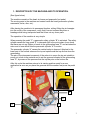
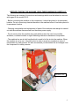
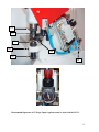
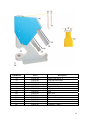
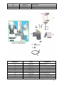
Model PG-21
Pneumatic Grommet Machine
Operating Manual
(800) 624-2408 (530) 626-9386 Fax (530) 626-5144
6686 Merchandise Way Diamond Springs, Ca 95619
www.sineqco.com
1
INTRODUCTION
PNEUMATIC MACHINE MODEL PG-21 FOR PLACING APPLICATIONS BY HAND
The function of this machine is the placement of applications or to punch holes (maximum
interior diameter of tube grommet 14mm) in materials that need these applications.
Specially recommended for placing grommets and washers in: awnings, curtains, advertising
signs, etc.
WARNINGS!
We hope you will take notice of these warnings and we would like to thank you for the purchase
of this machine.
User unawareness of the machine leads on many occasions to elementary doubts about its
operation.
Please read this instruction manual carefully for your guidance, in order to make the most of
your machine.
SINCLAIR EQUIPMENT DECLINES ALL RESPONSABILITY ON THE INCORRECT USE
OF THIS INSTRUCTION MANUAL.
IDENTIFICATION OF THE MACHINE:
The machine has an aluminium plate indicating the following:
Name of manufacturer
Year of manufacture
Model and serial number
Power in kw
Maximum pressure in bars (pneumatics system)
EC Brand
Weight in kg
Keep a record of this information for future support.
Serial Number:__________________
Date of Purchase:_______________
2
1. DESCRIPTION OF THE MACHINE AND ITS OPERATION.
(See figure below)
The machine consists of the head, air hoses and pneumatic foot pedal.
The moving parts in the machine are located inside the head (pneumatic cylinder,
manometer, axles, dies, etc.).
After placing the machine in its permanent location, without fitting the air hosepipe
into the mouth of the compressor, verify that it has not suffered any blow or
breakage while being transported and that it has not any loose parts.
The operation of the machine is very simple:
When pressing the pedal “C” a pneumatic safety cylinder “B” is activated. The safety
cylinder causes the ring guard “E” to descend right to the point where it can check
that there are not any fingers or hands in the grommeting area “D” and activates the
micro end of race which sets the pneumatic cylinder “A” in motion.
The pneumatic cylinder “A” causes the vertical axles to descend. Attached to the
lower part of the vertical axles are the top set spindle and the top die that does the
grommeting.
The aim of the downward movement of the axles is to cause the top-set spindle to
punch out a hole in the material and to set the grommet situated in the grommeting
area “D”, by means of the pressure that the top-die puts on the bottom die.
After this cycle the machine returns to its starting position ready for a new
application as soon as you place the grommet and the washer and press the pedal
“C”.
C
A
B
D
E
3
Technical Data:
HEAD MEASUREMENTS:
DEPTH: 30 cm
WIDTH: 11’5 cm
HEIGHT: 38 cm
WEIGHT (with pneumatic pedal): 14 Kg
Installation:
The operator can work in a seated or a standing position, depending on the
height of the machine.
The minimum space recommended must be sufficient to keep the safety
space in all directions for the operator to work properly. The buyer of the
machine usually places the machine on a table.
The machine model PG-21 needs at least 6 atmospheres of pressure from
the air compressor.
WARNING: FOR BETTER OPERATION THE COMPRESSOR HOSE PIPE
SHOULD NOT BE COMPLETELY STRETCHED.
Machine Handling:
The transportation of this machine requires a series of operations.
Some of these operations may imply dangerous situations so please follow the
following advise:
- Never stand beneath the cargo.
- Always lift the cargo gently.
- Avoid balancing the cargo.
- No brisk movements.
- Do not place yourself in the cargo moving trajectory.
- Use the correct equipment to move cargos.
- Check this equipment periodically.
REMEMBER: THE MACHINE MUST NOT BE OVERTURNED.
4
BEFORE STARTING THE MACHINE, READ THESE WARNINGS CAREFULLY.
The following are a series of instructions and warnings which must be taken into account
with regard to the model PG-21.
- Before connecting the machine to the compressor, it should be placed in its permanent
location. Do not connect any electrical devices to the machine before it has been placed in
its permanent location.
- Cleaning, manipulation and replacement of parts of the machine must always be carried
out with the machine disconnected from the mains power supply.
- Do not remove from the machine any parts which protect the user from possible
accidents, or adhesive labels or signs indicating electrical or hazardous components.
- The machine has an air inlet handle which is used to let the air into the machine. When
the machine is not in use, it should be shut in order to avoid any accidents in case of
manipulation by third persons. We also recommend you disconnect the air hosepipe from
the compressor for safety reasons.
Air Inlet Valve
5
Machine Description
Maximum interior diameter of grommet and washer is 12mm.
The machine perforates and sets the grommet with the washer at the same time.
Each set of dies sets only one grommet and washer model; the grommet models may differ
in: the head size “B”, the length “C”, the interior diameter of tube “A”, the thickness, etc; and
the washer models may differ in: the exterior diameter “B”, the length , the interior diameter
of washer hole “A”, the washer shape, etc.
SINCLAIR EQUIPMENT RECOMMENDS YOU TO USE ALWAYS THE SAME TYPE
OF GROMMET AND WASHER FOR WHICH THE MACHINE WAS DESIGNED. In
order for the machine to set different grommet and washer models, certain parts need to be
changed.
Sinclair Equipment will accept no responsibility arising from the use of this machine in any
way different from that which is described in this instruction manual.
Grommet
Grommet Measurements Washer Measurements
8mm Plastic Grommet
A: 8mm
B: 15mm
C: 8mm
No washer is used for
8mm grommet.
12mm Plastic Grommet
A: 12mm
B: 26mm
C: 8.3mm
A: 15mm
B: 24mm
6
SETTING UP THE MACHINE FOR ITS OPERATION
Before starting the machine for the first time, and each time the location of the machine is
changed, or any changes are made in parts or any adjustments are done to it, we recommend
the following steps:
After placing and making the machine level in its permanent location “STILL WITHOUT
PLUGGING IT IN”, lubricate it with SAE 40 type oil in the grease cups and red marks. Let
the oil have enough time to cover the parts and then clean the excess oil that might remain or
drip.
To verify the machine is not blocked or might have suffered a blow or breakage:
1- Remove the top cover,
2- Verify the machine is not blocked or that it has any loose parts.
3- Put the cover back and fasten the 4 allen screws.
4- Lubricate the parts as indicated.
ADJUSTMENTS
DISCONNECT THE MACHINE TO CHANGE THE DIES, ADJUST THE
PRESSURE, ETC
For an optimal operation, the machine has to be adjusted for each type of material and
grommet, keeping the parts that do the grommeting (dies and spindle) in good condition.
The bottom and top dies #219 and #217, and the top set spindle #218 are the parts that need
to be replaced regularly due to the normal use of the machine. You will realize that they have
to be replaced when the machine does not cut cleanly and / or the grommeting is defective.
We recommend you always have spare dies.
If you have to remove any part meant for the safety of the operator in order to do these
adjustments (for example: acrylic cover, ring guard), remember to put them back where they
belong.
7
For the following procedures, refer to the diagram on page 11
CHANGE OF DIES FOR THE SAME GROMMET AND / OR WASHER SIZE
Changing the bottom die #19:
With the machine disconnected from the compressor (and from the power source if it has any
electrical devices).
- Shut the air inlet part #260,
- Turn the ring guard # 306 by loosening the allew screw #278 that holds it,
- Get the puncher into the side hole of the die #219, and then turn it counterclockwise in
order to unscrew the die,
- Fit in the new bottom die #219 and secure,
- Put back the ring guard #306 and secure it through allen screw #278,
- Adjust the cutting and grommeting pressure, SEE CHAPTER ?. PRESSURE
ADJUSTMENTS, page ?,
- Check the ring guard adjustments, SEE CHAPTER ?. RING GUARD ADJUSTMENTS,
page?.
Changing the top-set spindle #218 and the top die #217:
With the machine disconnected from the compressor (and from the power source if it has any
electrical devices).
- Shut the air inlet part #260,
- Turn the ring guard #306 by loosening the allen screw #278 that holds it,
- Turn the nut #238 slightly counterclockwise,
- In order to remove the top die #217 together with the top-set spindle #218, you will have to
fit the puncher into the side hole of the top die #217, and turn it counterclockwise,
- Fit in the new spindle #218 and the new top die #217,
- in order to screw in the top die #217 together with the top set spindle #218 you will have to
get the puncher into the side hole of the top die #217 and turn it clockwise,
- Turn the nut #238 slightly clockwise in order to fix the parts,
- Screw up the ring guard (through allen screw #278),
- Adjust the cutting and grommeting pressure.
- Check the ring guard adjustments.
The machine model PG-21 can be adjusted for placing grommets with washers in
different types of material and in different thicknesses.
Machine model PG-21 has two vertical axles:
# 121 the driving stem that adjusts the cutting pressure (to punch a hole in the material), and
# 122 the top set spindle that adjusts the pressure of the grommeting.
CAUTION: For adjusting the pressure of the machine, it will be necessary to connect the air
hosepipe to the compressor and open the air inlet handle #260. Please be very careful while
doing these adjustments, always making sure that your hands and fingers are out of the
grommeting area and that nobody can press the foot pedal, which would cause the top set to
come down and catch a hand or finger.
8
For adjusting the cutting pressure (the cutting pressure punches a hole in the material), you
have to turn the bottom die # 219 to the right or to the left, so that when you start the machine
and press the foot pedal, the top set spindle # 218 barely touches the bottom die # 219.
With the machine disconnected from the compressor (and from the power source if it has any
electrical devices).
- Unscrew the threaded pin # 194 that holds the bottom die holder # 230,
- You must remember that the top set spindle # 218 always reaches the same point on its way
down and might hit the top of the bottom die # 219. Get a puncher in the side hole of the die
# 219, turn it to the right or to the left until the bottom die is in the right position.
If you want to know if the cutting pressure is correct, there is a simple way of checking it out:
you get a puncher in the side hole of the bottom die # 219 and by means of the puncher turn
the bottom die # 219 clockwise so it may come down a little bit, then get a piece of paper
(hold the piece of paper carefully, keeping you hands and fingers off the grommeting area) in
between the bottom die # 219 and the top set spindle # 218, then (with the machine
connected to the compressor and the air inlet # 260 in the open position) press the pneumatic
pedal while turning the bottom die # 219 counterclockwise until you manage to punch a hole
in the piece of paper.
- Disconnect the machine from the compressor and shut the air inlet #260,
- Screw up the threaded pin #194 so that it holds the bottom die holder # 230 and the bottom
die # 219.
- Check the ring guard adjustments, SEE PAGE 10.
If you wish to adjust the tightness of setting, you must turn the top die #217 to the right or to
the left. The top die is the die that does the grommeting.
With the machine disconnected from the compressor (and from the power source if it has any
electrical devices).
- Unscrew the nut nº 238 slightly counterclockwise,
- Get the puncher into the side hole of the die # 217, turn it to the right or left by causing the
top die # 217 to move downwards or upwards until it reaches an optimum position. The
higher the top die # 217, the lesser the pressure of the grommeting.
In order to achieve the correct pressure (with the machine connected to the compressor the
air inlet # 260 in the open position, and with your fingers and hands out the grommeting
area), press down the pedal and then adjust the dies so that the distance at its lowest point
between the top die # 217 and the bottom die # 219 should be the thickness of the material
that you wish to use.
- Disconnected the machine from the compressor and shut the air inlet nº 260,
- Screw back in the nut nº 238,
- Verify the ring guard adjustments.
After all the pressures and parts have been adjusted, you must verify that all the screws and
nuts are tight.
9
RING GUARD ADJUSTMENTS
Whenever the machine is adjusted or modified or some parts are changed it is necessary to
adjust the safety device again (pneumatic safety cylinder # 265, end of race # 267, ring guard
# 306, etc) so that it may work properly.
- Connect the machine to the compressor and open the air inlet # 260,
- The safety manometer # 8 must indicate 1 kg by means of the safety control # 7,
- Shut the air inlet # 260 and disconnect the machine from the air compressor.
Loosen the screw for holding ring # 278 with the 3 mm allen wrench,
- Place the ring guard # 306 at about 6 mm from the bottom die # 219.
This adjustment can be done (with the air inlet # 260 in the shut position and the machine
disconnected from the compressor) by putting one side of the 4 mm allen wrench (it is
supplied together with the machine) on top of the bottom die # 219, you lower the ring guard
# 306 until it touches the side of the 4 mm allen wrench.
- Tighten the screw for holding ring # 278 with the 3 mm allen wrench (it is supplied together
with the machine).
Before connecting the machine to the compressor, verify that all the parts are tightened up.
CHANGE OF DIES FOR ANOTHER GROMMET AND/OR WASHER SIZE
The machine model PG-21 can place two different sizes of grommets and washers.
8mm and 12mm.
If you wish to set a new grommet and washer size, you will have to replace some parts of the
machine.
- The new set of dies for the new size,
- Adaptors for the new size. These adaptors are not always the same and vary according to
the grommet and washer sizes.
In order to avoid any problems, Sinclair Equipment recommends that whenever you ask for a
new set of dies for a new grommet and washer size, please show us the following references:
- The reference of the machine,
- The reference of the grommet and washer models that the machine is setting,
- The reference of the new grommet with washer model that you want to place.
With this information, we can show you the parts you must replace.
The ring guard # 306 varies in size according to the grommets and washers size.
The changes of dies and parts, the pressure adjustments, the possible breakdowns, etc, are the
same that are shown in this manual.
REMEMBER THAT AFTER CHANGING DIES, YOU MUST ALWAYS ADJUST
THE CUTTING AND THE GROMMETING PRESSURE AND ALSO THE RING
GUARD.
10
238
217
219
194
306
230
260
Recommended pressure is 87-90 psi. Input regulator must be used with the PG-21.
11
MAINTENANCE
MECHANICAL PART OF THE MACHINE
For an optimal operation of the machine, it is recommended that you keep some parts clean
and always lubricated. The cleaning should ALWAYS be done with the machine
disconnected from the electrical power source and the compressor.
The pedal we press to operate the machine, should always be clean and clear of any debris
that could prevent it’s normal operation.
The exterior of the machine should be cleaned with a rag that will not leave threads, so that
the threads can not be stuck to the machine.
The head of the machine has two exterior grease fittings #62. You must use a manual
pressure oil can to inject oil (the oil type to be used should be “SAE 40”) into the grease cups
two or three times a week. We recommend to do this at the end of the job, and clean up the
possible excess oil the next day.
During the first month of operation it must be done twice per week. After the first month it
only needs to be done once a week.
If the machine is going to go for a long period of time without use, it will be necessary to do
a general cleaning, and greasing in the indicated spots, disconnecting it from the compressor
or from the power source (if it has any electrical devices), and then cover it so that it is
protected from the dust and/or humidity.
PNEUMATIC PART OF THE MACHINE
The pneumatic part of the machine does not need any type of maintenance.
The machine must be connected to a compressor provided with an oil strainer, an air filter,
and a manometre for adjusting the pressure.
12
TROUBLESHOOTING
PROBLEM
THE MACHINE DOES
NOT OPERATE WHEN
PRESSING THE FOOT
PEDAL.
DEFECTIVE GROMMETING.
IT WILL NOT CUT OR LEAVE
MATERIAL RESIDUALS.
THE RING GUARD COMES
DOWN, BUT THE DIE DOES
NOT.
CAUSE
SOLUTION
Make sure the air inlet is connected
to the compressor.
Make sure the air inlet is in the
open position.
Make sure the correct air pressure
is supplied
The bottom die is worn out or
broken.
Incorrect tightness of setting.
Incorrect adjustment of pneumatic
pressure.
Connect It
The bottom die or the top set
spindle are worn or broken.
Replace it with a new one.
Incorrect tightness of setting.
See adjustments section of manual.
The height of the ring guard is not
adjusted properly.
See the ring guard adjustment
section of manual.
Open The Handle
Make sure the compressor is
supplying the correct air pressure.
Replace.
See adjustments section of manual.
The manometer must indicate a
minimum pressure of 6 kg.
13
Schematic #
Part#
62
63
64
125
126
135
161
162
194
204
205
206
207
PGR21062
PGR21063
PGR21064
PGR21125
PGR21126
PGR21135
PGR21161
PGR21162
PGR21194
PGR21204
PGR21205
PGR21206
PGR21207
Description
Grease cups (Set of 2)
Long lubrication tube
Short lubrication tube
Left cylinder guard
Right cylinder guard
Hold guard
Head
Top Cover
Threaded pin for bottom die cover
Pneumatic foot pedal
Silecer
Connector ¼ tube 4
Connector ¼ tube 8
14
Schematic #
Part#
111
112
113
114
115
116
117
118
119
120
PGR21111
PGR21112
PGR21113
PGR21114
PGR21115
PGR21116
PGR21117
PGR21118
PGR21119
PGR21120
Description
Lever pin
Guide wheel pin
Driving stem guide wheel
Pin for die spindle
Connecting rod
Pin for connecting rod
Bolt for yoke
Nut for yoke
Yoke
Lever
15
121
122
281
PGR21121
PGR21122
PGR21281
Driving Stem
Top set spindle
Ring for 12 connecting rod pin
Schematic #
Part#
21
123
128
265
267
275
276
278
304
306
PGR21021
PGR21123
PGR21128
PGR21265
PGR21267
PGR21275
PGR21276
PGR21278
PGR21304
PGR21306
Description
M5 elbow tube
Screw for part #304
Screw for holding part #267
Pneumatic safety cylinder
End of race
Part for holding ring guard
Nut for holding part
Screw attaching ring guard
Part for holding cylinder
Ring guard
16
Schematic #
Part#
2
4
7
8
10
11
12
15
16
17
18
19
20
22
23
24
207
260
271
273
PGR21002
PGR21004
PGR21007
PGR21008
PGR21010
PGR21011
PGR21012
PGR21015
PGR21016
PGR21017
PGR21018
PGR21019
PGR21020
PGR21022
PGR21023
PGR21024
PGR21207
PGR21260
PGR21271
PGR21273
Description
Hinge for cylinder #271
Support for valve
Safety control 0-2 kg
Safety manometer
Silencer 1/8
Reduction
Buttress 1/8
Elbow 1/8
Elbow ¼ (2)
Elbow ¼ tube 8
Elbow ¼ tube 4
Elbow 1/8 tube 8 (4)
Elbow 1/8 tube 4
Side T ¼ tube 8
Male side T ¼
Halfmoon (2)
Connector ¼ tube 8 (3)
Air handle ¼
Part #271 cylinder 63x90
Part #273 valve 1/8
17
Schematic #
Part#
21
217
218
219
229
230
238
241
242
243
244
245
246
247
248
249
251
254
306
PGR21021
PGR21217
PGR21218
PGR21219
PGR21229
PGR21230
PGR21238
PGR21241
PGR21242
PGR21243
PGR21244
PGR21245
PGR21246
PGR21247
PGR21248
PGR21249
PGR21251
PGR21254
PGR21306
Description
J set of dies (Specify size)
Top die grommet & washer *
Top set spindle grommet & washer *
Bottom die grommet & washer *
Spring for top set spindle *
Bottom die holder *
Nut for adjusting the top die #217 *
Support front guide #240
Nuts (2)
Washers (2)
Part for holding front guide #240
Support front guide #240 with hole
Part for holding separator #250
Side axle
Part for holding the side guide #247
Nut for side axle #247
Nut for part #250
Front guide
Part #306 ring guard *
18
Tools And Parts
Tools:
Along with your machine, you will find all the necessary tools for adjustments and
maintenance.
Parts
Although the PG-21 doesn’t come with any parts, Sinclair Equipment recommends having an
extra bottom die, or set of dies for spares.
19
20
NOTES
21