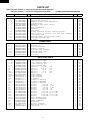
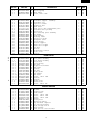
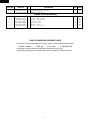
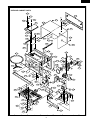
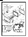
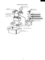
1
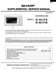
R-1214
SERVICE MANUAL
S83M215R1214E
OVER THE COUNTER
MICROWAVE OVEN
MODELS
R-1214
In the interest of user-safety the oven should be restored to its
original condition and only parts identical to those specified should
be used.
WARNING TO SERVICE PERSONNEL: Microwave ovens contain circuitry capable of producing very high voltage and
current. Contact with the following parts may result in a
severe, possibly fatal, electrical shock. (High Voltage Capacitor, High Voltage Power Transformer, Magnetron, High Voltage Rectifier Assembly, High Voltage Harness etc..)
This is a supplemental Service Manual for Model R-1214. This model is quite similar to base model
R-1200 and R-1201. Use this supplemental manual together with the Base Models Service Manual (Reference No.
is SY130R1200X//) for complete operation, service information, etc..
TABLE OF CONTENTS
Page
PRECAUTIONS TO BE OBSERVED BEFORE AND DURING SERVICING TO
AVOID POSSIBLE EXPOSURE TO EXCESSIVE MICROWAVE ENERGY ................... INSIDE FRONT COVER
BEFORE SERVICING ...................................................................................................... INSIDE FRONT COVER
WARNING TO SERVICE PERSONNEL ................................................................................................................ 1
MICROWAVE MEASUREMENT PROCEDURE ................................................................................................... 2
FOREWORD AND WARNING ............................................................................................................................... 3
PRODUCT SPECIFICATIONS .............................................................................................................................. 4
CONTROL PANEL ................................................................................................................................................. 4
PARTS LIST ..........................................................................................................................................................5
PACKING AND ACCESSORIES .........................................................................................................................10
This document has been published to be used for after
sales service only.
The contents are subject to change without notice.
SHARP CORPORATION
35
R-1214
PRECAUTIONS TO BE OBSERVED BEFORE AND
DURING SERVICING TO AVOID POSSIBLE EXPOSURE TO EXCESSIVE MICROWAVE ENERGY
(a) Do not operate or allow the oven to be operated with the door open.
(b) Make the following safety checks on all ovens to be serviced before activating the magnetron or other
microwave source, and make repairs as necessary: (1) interlock operation, (2) proper door closing, (3) seal
and sealing surfaces (arcing, wear, and other damage), (4) damage to or loosening of hinges and latches,
(5) evidence of dropping or abuse.
(c) Before turning on microwave power for any service test or inspection within the microwave generating
compartments, check the magnetron, wave guide or transmission line, and cavity for proper alignment,
integrity, and connections.
(d) Any defective or misadjusted components in the interlock, monitor, door seal, and microwave generation
and transmission systems shall be repaired, replaced, or adjusted by procedures described in this manual
before the oven is released to the owner.
(e) A microwave leakage check to verify compliance with the Federal Performance Standard should be
performed on each oven prior to release to the owner.
BEFORE SERVICING
Before servicing an operative unit, perform a microwave emission check as per the Microwave
Measurement Procedure outlined in this service manual.
If microwave emissions level is in excess of the specified limit, contact SHARP ELECTRONICS
CORPORATION immediately @1-800-237-4277.
If the unit operates with the door open, service person should 1) tell the user not to operate the oven
and 2) contact SHARP ELECTRONICS CORPORATION and Food and Drug Administration's
Center for Devices and Radiological Health immediately.
Service personnel should inform SHARP ELECTRONICS CORPORATION of any certified unit
found with emissions in excess of 4mW/cm2. The owner of the unit should be instructed not to use
the unit until the oven has been brought into compliance.
36
R-1214
WARNING TO SERVICE PERSONNEL
Microwave ovens contain circuitry capable of producing very high voltage and current, contact with
following parts may result in a severe, possibly
fatal, electrical shock.
(Example)
High Voltage Capacitor, High Voltage Power Transformer, Magnetron, High Voltage Rectifier Assembly, High Voltage Harness etc..
Read the Service Manual carefully and follow all
instructions.
Don't Touch !
Danger High Voltage
When the testing is completed,
1. Disconnect the power supply cord, and then remove
outer case.
2. Open the door and block it open.
3. Discharge high voltage capacitor.
4. Reconnect the leads to the primary of the power
transformer.
5. Reinstall the outer case (cabinet).
6. Reconnect the power supply cord after the outer case is
installed.
7. Run the oven and check all functions.
Before Servicing
1. Disconnect the power supply cord
outer case.
2. Open the door and block it open.
3. Discharge high voltage capacitor.
, and then remove
WARNING:RISK OF ELECTRIC SHOCK.
DISCHARGE THE HIGH-VOLTAGE
CAPACITOR BEFORE SERVICING.
The high-voltage capacitor remains charged about 60
seconds after the oven has been switched off. Wait for 60
seconds and then short-circuit the connection of the highvoltage capacitor (that is the connecting lead of the highvoltage rectifier) against the chassis with the use of an
insulated screwdriver.
After repairing
1. Reconnect all leads removed from components during
testing.
2. Reinstall the outer case (cabinet).
3. Reconnect the power supply cord after the outer case is
installed.
4. Run the oven and check all functions.
Whenever troubleshooting is performed the power supply
must be disconnected. It may, in some cases, be necessary
to connect the power supply after the outer case has been
removed, in this event,
1. Disconnect the power supply cord, and then remove
outer case.
2. Open the door and block it open.
3. Discharge high voltage capacitor.
4. Disconnect the leads to the primary of the power
transformer.
5. Ensure that these leads remain isolated from other
components and oven chassis by using insulation tape.
6. After that procedure, reconnect the power supply cord.
Microwave ovens should not be run empty. To test for the
presence of microwave energy within a cavity, place a cup
of cold water on the oven turntable, close the door and set
the power to HIGH and set the microwave timer for two (2)
minutes. When the two minutes has elapsed (timer at zero)
carefully check that the water is now hot. If the water
remains cold carry out Before Servicing procedure and reexamine the connections to the component being tested.
When all service work is completed and the oven is fully
assembled, the microwave power output should be checked
and microwave leakage test should be carried out.
1
R-1214
MICROWAVE MEASUREMENT PROCEDURE
A. Requirements:
1) Microwave leakage limit (Power density limit): The power density of microwave radiation emitted by a microwave oven
should not exceed 1mW/cm2 at any point 5cm or more from the external surface of the oven, measured prior to acquisition
by a purchaser, and thereafter (through the useful life of the oven), 5 mW/cm2 at any point 5cm or more from the external
surface of the oven.
2) Safety interlock switches: Primary interlock switch shall prevent microwave radiation emission in excess of the
requirement as above mentioned, secondary interlock relay and door sensing switch shall prevent microwave radiation
emission in excess of 5 mW/cm2 at any point 5cm or more from the external surface of the oven.
B. Preparation for testing:
Before beginning the actual measurement of leakage, proceed as follows:
1) Make sure that the actual instrument is operating normally as specified in its instruction booklet.
Important:
Survey instruments that comply with the requirement for instrumentation as prescribed by the performance standard
for microwave ovens, 21 CFR 1030.10(c)(3)(i), must be used for testing.
2) Place the oven tray in the oven cavity.
_15 ml (9.8 oz) of tap water initially at 20+
_ 5 C (68 F) in the center of the oven cavity.
3) Place the load of 275+
The water container shall be a low form of 600 ml (20 oz) beaker with an inside diameter of approx. 8.5 cm (3-1/2 in.)
and made of an electrically nonconductive material such as glass or plastic.
The placing of this standard load in the oven is important not only to protect the oven, but also to insure that any leakage
is measured accurately.
4) Set the cooking control on Full Power Cooking Mode
5) Close the door and select a cook cycle of several minutes. If the water begins to boil before the survey is completed,
replace it with 275 ml of cool water.
C. Leakage test:
Closed-door leakage test (microwave measurement)
1) Grasp the probe of the survey instrument and hold it perpendicular to the gap between the door and the body of the oven.
2) Move the probe slowly, not faster than 1 in./sec. (2.5 cm/sec.) along the gap, watching for the maximum indication on
the meter.
3) Check for leakage at the door screen, sheet metal seams and other accessible positions where the continuity of the metal
has been breached (eg., around the switches, indicator, and vents).
While testing for leakage around the door pull the door away from the front of the oven as far as is permitted by the closed
latch assembly.
4) Measure carefully at the point of highest leakage and make sure that the highest leakage is no greater than 4mW/cm2,
and that the primary interlock switch and the secondary interlock relay do turn the oven OFF before any door movement.
NOTE: After servicing, record data on service invoice and microwave leakage report.
2
R-1214
SERVICE MANUAL
OVER THE COUNTER
MICROWAVE OVEN
R-1214
FOREWORD
This Manual has been prepared to provide Sharp Electronics Corp. Service Personnel with Operation and Service
Information for the SHARP OVER THE COUNTER MICROWAVE OVEN, R-1214.
Model R-1214 is quite similar to base models R-1200 and R-1201 (Reference No. is SY130R1200X//).
It is recommended that service personnel carefully study the entire text of this manual and base model service manual so
that they will be qualified to render satisfactory customer service.
Check the interlock switches and the door seal carefully. Special attention should be given to avoid electrical shock and
microwave radiation hazard.
WARNING
Never operate the oven until the following points are ensured.
(A) The door is tightly closed.
(B) The door brackets and hinges are not defective.
(C) The door packing is not damaged.
(D) The door is not deformed or warped.
(E) There is not any other visible damage with the oven.
Servicing and repair work must be carried out only by trained service personnel.
DANGER
Certain initial parts are intentionally not grounded and present a risk of electrical shock only during servicing.
Service personnel - Do not contact the following parts while the appliance is energized;
High Voltage Capacitor, Power Transformer, Magnetron, High Voltage Rectifier Assembly, High Voltage
Harness;
If provided, Vent Hood, Fan assembly, Cooling Fan Motor.
All the parts marked "*" on parts list are used at voltages more than 250V.
Removal of the outer wrap gives access to voltage above 250V.
All the parts marked "∆" on parts list may cause undue microwave exposure, by themselves, or when they are damaged,
loosened or removed.
SHARP ELECTRONICS CORPORATION
SHARP PLAZA, MAHWAH,
NEW JERSEY 07430-2135
3
R-1214
PRODUCT SPECIFICATION
ITEM
Power Requirements
Power Output
Case Dimensions
Cooking Cavity Dimensions
1.5 Cubic Feet
Hood lamp
Control Complement
Oven Cavity Light
Safety Standard
Weight
DESCRIPTION
120 Volts / 13.0 Amperes
60 Hertz
Single phase, 3 wire grounded
1100 watts (IEC TEST PROCEDURE)
Operating frequency of 2450MHz
Width
23-7/8"
Height 15-9/16"
Depth 14-1/16"
Width
17-1/2"
Height 14-15/16"
Depth
9-7/8"
2 bulbs, 20W x 2, Incandescent light bulbs
Touch Control System
Clock ( 1:00 - 12:59 )
Timer (0 - 99 min. 99 seconds)
Microwave Power for Variable Cooking
Repetition Rate;
HIGH ................................................ Full power throughout the cooking time
P-90 .................................................................... approx. 90% of Full Power
P-80 .................................................................... approx. 80% of Full Power
P-70 .................................................................... approx. 70% of Full Power
P-60 .................................................................... approx. 60% of Full Power
P-50 .................................................................... approx. 50% of Full Power
P-40 .................................................................... approx. 40% of Full Power
P-30 .................................................................... approx. 30% of Full Power
P-20 .................................................................... approx. 20% of Full Power
P-10 .................................................................... approx. 10% of Full Power
P-0 .................................................... No power throughout the cooking time
CUSTOM HELP pad, KEEP WARM PLUS pad
ACCENT LIGHT pad, TASK LIGHT pad, REHEAT pads
SENSOR COOK CENTER pad DEFROST CENTER pad
INSTANT SENSOR pads, Number selection pads
POWER LEVEL pad, TIMER / CLOCK pad
STOP/CLEAR pad, START/MINUTE PLUS pad
20W x 1 Incandescent light bulb
UL Listed
FCC Authorized
DHHS Rules, CFR, Title 21, Chapter 1, Subchapter J
Approx. 50 lbs.
CONTROL PANEL
NOTE: Some one-touch cooking features such as "MINUTE PLUS" are disabled after three minutes when the oven
is not used. These features are automatically enabled when the door is opened and closed or STOP/CLEAR
button is pressed.
4
R-1214
PARTS LIST
Note: The parts marked "∆" may cause undue microwave exposure.
The parts marked "*" are used in voltage more than 250V.
"§ " MARK: PARTS DELIVERY SECTION
PART NO.
§
1- 1
1- 2
1- 3
1- 4
1- 5
1- 6
1- 7
1- 8
1- 9
1-10
1-11
1-12
1-13
1-14
1-15
FH-DZB016MRY0
RC-QZB018MRE0
QFS-TA013WRE0
RMOTDA252WRZZ
QFS-TA014WRE0
RMOTEB031MRE0
RTRN-B068MRE0
RV-MZA318WRZZ
QFSHDB003MRE0
QSW-MA085WRE0
FFS-BA016/KIT
FACCDB011MRE0
QSOCLB006MRE0
RLMPTA086WRZZ
FDTCTA225WRKZ
M
M
M
M
M
M
M
M
M
M
M
M
M
M
M
High voltage rectifier assembly
High voltage capacitor
Temperature fuse 150 C (Magnetron)
Turntable motor
Temperature fuse 150 C (Cavity)
Fan motor
Power transformer
Magnetron
Fuse holder
Primary interlock and door sensing switches
Monitor switch (V-16G-2C25) with fuse (20A) assembly
Power supply cord
Oven lamp socket and hood lamp sockets
Oven lamp and hood lamps
AH sensor
2- 1
2- 2
2- 3
2- 4
2- 5
2-5-1
2-5-2
2- 6
FDECAB044MRK0
GDAI-B066MRP0
GCABUB108MRP0
TMAPCB068MRR0
FANGKB009MRY0
LANGQB016MRP0
PGLSPB004MRE0
PCOVPB099MRT0
M
M
M
M
M
M
M
M
Bottom sash
Base plate R
Outer case cabinet
Schematic diagram
Hood lamp glass assembly
Hood lamp glass angle
Hood lamp glass
Base cover
3- 1
3- 1A
3- 1B
3- 1C
3- 1D
C1
C2
C3
C21
C50-51
D1-4
D20-24
D40
IC2
Q1
Q21
Q22
R1
R3
R4
R5
R50
R51
R52
R53
R54
RY1-2
RY3-4
SP1
T1
VRS1
ZD1
3- 2
DPWBFB104MRU0
QCNCMA017JDZZ
QCNCMA275DRE0
QCNCMA335DRE0
QCNCMA237DRE0
RC-KZA087DRE0
VCEAB31VW108M
VCEAB31VW106M
VCEAB31VW106M
RC-KZA087DRE0
RH-DZA006PRE0
VHD1SS270A/-1
VHD1SS270A/-1
VHIBA4558//-6
VS2SB1238//-3
VSKRC243M//-3
VSKRA101M//-3
VRS-B13AA681J
VRD-B12EF242J
VRD-B12EF332J
VRS-B13AA681J
VRS-B13AA331J
RR-DZA285DRZZ
RR-DZA286DRZZ
VRN-B12EK182F
VRN-B12EK364F
RRLY-A113DRE0
RRLY-B004MRE0
RALM-A014DRE0
RTRNPB017MRE0
RH-VZA032DRE0
VHEHZ161///-1
HPNLCB187MRF0
M
M
J
J
J
J
J
J
J
J
J
J
J
J
J
J
J
J
J
J
J
J
J
J
J
J
M
M
J
M
J
J
M
Power unit
3-pin connector CN-A
2-pin connector CN-B
11-pin connector CN-C
3-pin connector CN-F
Capacitor
0.1 uF
Capacitor
1000 uF
Capacitor
10 uF
Capacitor
10 uF
Capacitor
0.1 uF
Diode (1N4002)
Diode (1SS270A)
Diode (1SS270A)
IC (BA4558)
Transistor (2SB1238)
Transistor (KRC243M)
Transistor (KRA101M)
Resistor
680 ohm
Resistor
2.4k ohm
Resistor
3.3k ohm
Resistor
680 ohm
Resistor
330 ohm
Resistor
3.32k ohm
Resistor
3.57k ohm
Resistor
1.8k ohm
Resistor
360k ohm
Relay (DU24D1-1PR(M))
Relay (FTR-F3AA024E)
Buzzer (PKM22EPT)
Transformer
Varistor (10G471K)
Zener diode (HZ16-1)
Right panel
REF. NO.
DESCRIPTION
Q'TY CODE
ELECTRIC PARTS
*
*
*
*
1
1
1
1
1
1
1
1
1
2
1
1
3
3
1
AT
AG
AE
AL
AF
AR
BC
BK
AD
AE
AF
AQ
AE
AE
AR
1
1
1
1
1
1
1
1
AH
AF
AZ
AB
AN
AG
AH
AR
1
1
1
1
1
1
1
1
1
2
4
5
1
1
1
1
1
1
1
1
1
1
1
1
1
1
2
2
1
1
1
1
1
AZ
AG
AB
AC
AD
AB
AF
AB
AB
AB
AD
AA
AA
AK
AA
AB
AB
AA
AA
AA
AA
AA
AC
AC
AA
AA
AG
AG
AG
AS
AE
AA
AR
CABINET PARTS
RIGHT PANEL PARTS
5
50V
35V
35V
35V
50V
_
+
_
+
_
+
_
+
1W
1/4W
1/4W
1W
1W
0.5%
0.5%
1.0%
1.0%
1/4W
1/4W
1/4W
1/4W
R-1214
REF. NO.
3- 3
3- 4
3- 5
3- 6
PART NO.
JBTN-B161MRF0
MSPRCA045WRE0
PSHEPB078MRR0
XEPSD30P10XS0
§
M
M
M
M
Open button
Button spring
Menu label
Screw; 3mm x 10mm
DESCRIPTION
4- 1
4- 2
4- 3
4- 4
4- 5
4- 6
4- 7
4- 8
4- 9
4-10
4-11
4-12
4-13
4-14
4-15
4-16
4-17
4-18
4-19
4-20
4-21
4-22
4-23
4-24
PDUC-B119MRF0
FROLPB025MRK0
NTNT-A108WREZ
LBNDKB009MRP0
PDUC-B111MRF0
MLEVPB016MRF0
*************
PPACGB014MRF0
PHOK-B018MRF0
FANGTB006MRY0
NFANPB006MRE0
LBSHC0037WRE0
MLEVFB008MRP0
PSKR-B014MRP0
PCOVPB085MRP0
MSPRTA046WRE0
LANGTB055MRP0
LSTPPB039MRF0
LSTPPB040MRF0
PDUC-B113MRP0
PDUC-B117MRF0
PCUSGB043MRP0
PCOVPB101MRP0
PCUSUB065MRP0
M
M
M
M
M
M
M
M
M
M
M
M
M
M
M
M
M
M
M
M
M
M
M
M
Exhaust duct
Turntable support assembly
Turntable tray
Capacitor holder
Magnetron duct
Open lever
Oven cavity (Not replaceable part)
Turntable motor packing
Latch hook
Unit mounting plate assembly
Fan blade
Cord bushing
Mounting lever
Bottom air guide
Waveguide cover
Latch spring
Chassis support
Upper door stopper
Lower door stopper
Fan duct
Orifice
Transformer cushion
Light cover
Cushion
5
5- 1
5- 2
5-2-1
5-2-2
5-2-3
5-2-4
5-2-5
5-2-6
5-2-7
5-2-8
5-2-9
5-2-10
5-2-11
5-2-12
5-2-13
5- 3
5- 4
5- 5
CDORFB343MRK0
FDORFB072MRT0
FCOV-B249MRK0
LSTPPB023MRF0
MSPRTA046WRE0
FUNTKB391MRE0
FW-VZB193MRE0
PCOVPB098MRP0
PCUSGB045MRP0
DUNT-B048MRK0
LHLD-A237WRFZ
LHLD-B020MRF0
PSHEPA786WREZ
XEPSD30P10XS0
PCUSUB067MRP0
PCUSUB069MRP0
GCOVHB045MRF0
PSHEPB016MRE0
XCPSD40P08000
M
M
M
M
M
M
M
M
M
M
M
M
M
M
M
M
M
M
M
Door assembly
Door panel assembly
Door frame assembly
Latch head
Latch spring
Key unit
11-pin wire harness
PWB cover
Cushion
LSI unit
Light guide
LCD holder
LED sheet
Screw : 3mm x 10mm
Cushion
Cushion
Choke cover
Sealer film
Screw : 4mm x 8mm
6- 1
6-1-1
6-1-2
6-1-3
6-1-4
6-1-5
6-1-6
6-1-7
6- 2
6- 3
6- 4
6- 5
6- 6
6- 7
6- 8
CFZK-B460MRK0
LBSHC0040MRE0
LX-BZ0195WRE0
LX-MZB001MRE0
XBRSD50P60000
XOTSD40P12000
XTSSD50P35000
XWHSD50-16300
LANG-B003MRP0
TINSEB358MRK0
TINSKB082MRR0
FW-VZB188MRE0
QW-QZB025MRE0
FW-VZB280MRE0
TCAUAB049MRR0
M
M
M
M
M
M
M
M
M
M
M
M
M
M
M
Installation material assembly
Grommet
Toggle screw
Cord holder
Screw : 5mm x 60mm
Screw : 4mm x 12mm
Screw : 5mm x 35mm
Washer
Scale plate
Operation manual
Top and Wall template
Low voltage harness
High voltage wire A
Main harness
DHHS service caution label
Q'TY CODE
1
AE
AA
1
1
AF
2
AB
OVEN PARTS
1
1
1
1
1
1
1
1
1
1
1
1
2
1
1
2
2
1
1
1
1
1
1
1
AH
AN
AN
AB
AF
AD
-AA
AF
AS
AC
AB
AC
AD
AH
AB
AD
AB
AB
AH
AC
AC
AE
AA
1
1
1
1
1
1
1
1
1
1
1
1
1
2
1
1
1
1
2
BK
AW
BF
AC
AB
AQ
AD
AB
BA
AC
AC
AD
AB
AB
AB
AG
AE
AA
1
1
4
1
2
3
6
2
2
1
1
1
1
1
2
AH
AC
AC
AB
AA
AA
AA
AA
AE
AE
AE
AT
AT
AU
AA
DOOR PARTS
∆
∆
∆
∆
MISCELLANEOUS
*
6
R-1214
REF. NO.
6- 9
6-10
6-11
PART NO.
TCAUAB050MRR0
TCAUAB048MRR0
QW-VZB011MRE0
§
M
M
M
DESCRIPTION
Monitor caution label
Revised DHHS/GRD C/label
Sensor ground wire
Q'TY CODE
1
AA
1
AB
1
AB
SCREWS, NUTS AND WASHERS
7777777-
1
2
3
4
5
6
7
XOTSF40P12000
XOTSD40P12000
XHTSD40P08RV0
LX-CZA038WRE0
LX-CZ0052WRE0
LX-BZA041WRE0
XCBSD30P08000
M
M
M
M
M
M
M
Screw :
Screw :
Screw :
Special
Special
Special
Screw :
4mm x
4mm x
4mm x
screw
screw
screw
3mm x
12mm
12mm
8mm
10
12
3
5
2
4
5
8mm
HOW TO ORDER REPLACEMENT PARTS
To have your order filled promptly and correctly, please furnish the following information.
1. MODEL NUMBER
2. REF. NO.
3. PART NO.
4. DESCRIPTION
Order Parts from the authorized SHARP parts Distributor for your area.
Defective parts requiring return should be returned as indicated in the Service Policy.
7
AA
AA
AA
AA
AA
AA
AA
R-1214
2
1
4
3
6
5
OVEN AND CABINET PARTS
7-7
A
A
4-10
6-11
7-2
1-15
7-4
1-12
2-3
4-1
4-12
7-4
B
B
7-4
7-7
B
7-2
1-5
7-7
4-17
7-4
2-4
A
7-2
6-11
C
4-16
C
4-17
7-1
4-13
6-10
4-3
D
7-8
7-3
D
1-3
7-4
7-3
7-3
4-4
1-6
1-2
4-16 4-20
B
4-7
4-2
2-1
4-11
7-5
4-8
6-8
1-8
4-5
1-10
1-4
F
4-9
1-14
1-10
1-7
1-11
1-13
1-14
F
1-11
1-9
7-2
7-6
1-13
7-7
7-3
4-23
4-22
6-8
5-2-4
G
G
4-24
7-1
2-2
7-1
7-2
2-5-2
2-6
7-2
7-2
7-1
7-1
4-14
2-5-1
H
7-1
7-1
1
E
6-9
4-6
H
1-1
A
4-21
4-15
2-5
7-3
4-13
7-2
E
7-6
2
4
3
8
5
6
R-1214
2
1
4
3
6
5
RIGHT PANEL PARTS
A
A
DOOR PARTS
7-2
3-6
3-1
4-18
5
B
4-19
5-5
3-5
B
5-3
5-4
3-2
C
C
3-4
3-3
5-1
5-2-13
5-2-7
D
5-5
5-2-5
5-2-11
D
5-2-4
5-2-12
5-2-9
5-2-8
5-2-10
5-2-3
5-2
MISCELLANEOUS
5-2-1
E
E
6-6
5-2-2
6-7
5-2-6
F
F
6-1
6-1-1
6-1-4
6-1-5
6-1-2
6-1-6
6-5
G
6-1-3
G
6-1-7
6-2
6-11
H
H
1
2
4
3
9
5
6
R-1214
PACKING AND ACCESSORIES
4-3 TURNTABLE TRAY
TOP PAD
6-2 SCALE PLATE
6-4 TOP & WALL TEMPLATE
DOOR PROTECTOR
6-3
WRAP COVER
OPERATION MANUAL
6-1 INSTALL MATERIAL ASSEMBLY
ACCESSORY PACK
BOTTOM PAD
Non-replaceable items
PACKING CASE
10
R-1214
COPYRIGHT © 2003 BY SHARP CORPORATION
ALL RIGHTS RESERVED.
No part of this publication may be reproduced, stored
in retrieval systems, or transmitted in any form or by
any means, electronic, mechanical, photocopying,
recording, or otherwise, without prior written permission of the publisher.
'03 SHARP CORP. (3S2400E) Printed in U.S.A
34