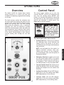
1
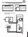
MODEL W1678 26" DOUBLE DRUM SANDER INSTRUCTION MANUAL Phone: 1-360-734-3482 • On-Line Technical Support: [email protected] COPYRIGHT © MAY, 2003 BY WOODSTOCK INTERNATIONAL, INC., REVISED DECEMBER, 2014 (MN) WARNING: NO PORTION OF THIS MANUAL MAY BE REPRODUCED IN ANY SHAPE OR FORM WITHOUT THE WRITTEN APPROVAL OF WOODSTOCK INTERNATIONAL, INC. Printed in Taiwan This manual provides critical safety instructions on the proper setup, operation, maintenance, and service of this machine/tool. Save this document, refer to it often, and use it to instruct other operators. Failure to read, understand and follow the instructions in this manual may result in fire or serious personal injury—including amputation, electrocution, or death. The owner of this machine/tool is solely responsible for its safe use. This responsibility includes but is not limited to proper installation in a safe environment, personnel training and usage authorization, proper inspection and maintenance, manual availability and comprehension, application of safety devices, cutting/sanding/grinding tool integrity, and the usage of personal protective equipment. The manufacturer will not be held liable for injury or property damage from negligence, improper training, machine modifications or misuse. Some dust created by power sanding, sawing, grinding, drilling, and other construction activities contains chemicals known to the State of California to cause cancer, birth defects or other reproductive harm. Some examples of these chemicals are: • Lead from lead-based paints. • Crystalline silica from bricks, cement and other masonry products. • Arsenic and chromium from chemically-treated lumber. Your risk from these exposures varies, depending on how often you do this type of work. To reduce your exposure to these chemicals: Work in a well ventilated area, and work with approved safety equipment, such as those dust masks that are specially designed to filter out microscopic particles. PAGE INTRODUCTION..................................................................................... 2 Woodstock Tech Support............................................................................ 2 Specifications.................................................................................. 3 ELECTRICAL REQUIREMENTS.................................................................... 8 ASSEMBLY......................................................................................... 10 220V Operation........................................................................................ 8 Extension Cords........................................................................................ 8 Grounding............................................................................................... 8 Unpacking.............................................................................................. 10 Box Contents.......................................................................................... 10 Shop Preparation..................................................................................... 11 Initial Cleaning........................................................................................ 11 Beginning............................................................................................... 12 Dust Port and Handles............................................................................... 13 Control Box............................................................................................ 13 Crank and Handle..................................................................................... 13 ADJUSTMENTS.................................................................................... 14 Drums and Pressure Rollers ....................................................................... 14 Dust Scoop Gap....................................................................................... 20 V-Belt Tension......................................................................................... 21 Conveyor Belt......................................................................................... 22 OPERATIONS...................................................................................... 23 Overview............................................................................................... 23 Control Panel.......................................................................................... 23 Basic Sanding.......................................................................................... 24 Troubleshooting....................................................................................... 27 MAINTENANCE.................................................................................... 29 General................................................................................................. 29 Sanding Belts.......................................................................................... 29 Lubrication............................................................................................. 30 Brush Replacement................................................................................... 31 Sandpaper Replacement............................................................................ 21 Bearing Replacement................................................................................ 32 General Cleaning..................................................................................... 34 Wiring Diagram........................................................................................ 35 WARRANTY........................................................................................ 49 USE THE QUICK GUIDE PAGE LABELS TO SEARCH OUT INFORMATION FAST! -1 - MAINTENANCE CLOSURE.......................................................................................... 37 Parts Breakdown and Parts List...............................................................38-45 OPERATIONS ADJUSTMENTS ASSEMBLY Standard Safety Instructions...................................................................... 4-5 Additional Safety Instructions for Drum Sanders............................................... 6 Avoiding Potential Injuries.......................................................................... 7 ELECTRICAL SAFETY.............................................................................................. 4 SAFETY INTRODUCTION TABLE OF CONTENTS INTRODUCTION INTRODUCTION Woodstock Technical Support Woodstock International, Inc. is committed to customer satisfaction. Our intent with this manual is to include the basic information for safety, setup, operation, maintenance, and service of this product. In the event that questions arise about your machine, please contact Woodstock International Technical Support at (360) 734-3482 or send e-mail to: [email protected]. Our knowledgeable staff will help you troubleshoot problems or process warranty claims. If you need the latest edition of this manual, you can download it from http://www.shopfox.biz. If you have comments about this manual, please contact us at: Woodstock International, Inc. Attn: Technical Documentation Manager P.O. Box 2309 Bellingham, WA 98227 Email: [email protected] -2- Drum Sander Motor.............. 5 HP, 220 VAC, 25 Amp., 3450 RPM, 60 Hertz, Single-Phase Drum Drive............................................................................... Dual V-Belt Drum Size.................................................................................. 6" x 273⁄4" Drum Surface Speed.............................................................................. 2300 FPM Drum Rotation........................................................Opposite of Feed Conveyor Conveyor Motor.............................. 1⁄3 HP, 60 VDC, 2 amp., 60 RPM, Varable Speed Conveyor Drive................................................................. Sprocket and Chain Conveyor Surface Speed.................................................................. 0-20 FPM Maximum Lumber Dimensions.................................................... 41⁄2" Thick x 26" Wide Minimum Lumber Dimensions............................................... 1⁄8" Thick x 9" Long Dust Port O.D................................................................................................4" Conveyor Table Size..................................................................261⁄8" x 301⁄4" Stand........................................................ Cabinet Style, Powder Coated Paint Bearings........................Both Serviceable and Permanently-Lubricated Ball Bearings Power Control.................................. Magnetic Switch, with Emergency Shut-Down Footprint.................................................................................. 36" x 233⁄4" Shipping Weight.............................................................................. 435 lbs. -3- INTRODUCTION Specifications SAFETY SAFETY For Your Own Safety, Read Manual Before Operating Machine The purpose of safety symbols is to attract your attention to possible hazardous conditions. This manual uses a series of symbols and signal words intended to convey the level of importance of the safety messages. The progression of symbols is described below. Remember that safety messages by themselves do not eliminate danger and are not a substitute for proper accident prevention measures—this responsibility is ultimately up to the operator! Indicates an imminently hazardous situation which, if not avoided, WILL result in death or serious injury. Indicates a potentially hazardous situation which, if not avoided, COULD result in death or serious injury. Indicates a potentially hazardous situation which, if not avoided, MAY result in minor or moderate injury. NOTICE This symbol is used to alert the user to useful information about proper operation of the equipment or a situation that may cause damage to the machinery. Standard Machinery Safety Instructions OWNER’S MANUAL. Read and understand this owner’s manual BEFORE using machine. ELECTRICAL EQUIPMENT INJURY RISKS. You can be shocked, burned, or killed by touching live electrical components or improperly grounded machinery. To reduce this risk, only allow an electrician or qualified service personnel to do electrical installation or repair work, and always disconnect power before accessing or exposing electrical equipment. TRAINED OPERATORS ONLY. Untrained operators have a higher risk of being hurt or killed. Only allow trained/supervised people to use this machine. When machine is not being used, disconnect power, remove switch keys, or lock-out machine to prevent unauthorized use—especially around children. Make workshop kid proof! DISCONNECT POWER FIRST. Always disconnect machine from power supply BEFORE making adjustments, changing tooling, or servicing machine. This eliminates the risk of injury from unintended startup or contact with live electrical components. DANGEROUS ENVIRONMENTS. Do not use machinery in areas that are wet, cluttered, or have poor lighting. Operating machinery in these areas greatly increases the risk of accidents and injury. EYE PROTECTION. Always wear ANSI-approved safety glasses or a face shield when operating or observing machinery to reduce the risk of eye injury or blindness from flying particles. Everyday eyeglasses are not approved safety glasses. MENTAL ALERTNESS REQUIRED. Full mental alertness is required for safe operation of machinery. Never operate under the influence of drugs or alcohol, when tired, or when distracted. -4- WEARING PROPER APPAREL. Do not wear clothing, apparel, or jewelry that can become entangled in moving parts. Always tie back or cover long hair. Wear non-slip footwear to avoid accidental slips, which could cause loss of workpiece control. FORCING MACHINERY. Do not force machine. It will do the job safer and better at the rate for which it was designed. HAZARDOUS DUST. Dust created while using machinery may cause cancer, birth defects, or long-term respiratory damage. Be aware of dust hazards associated with each workpiece material, and always wear a NIOSH-approved respirator to reduce your risk. STABLE MACHINE. Unexpected movement during operation greatly increases risk of injury or loss of control. Before starting, verify machine is stable and mobile base (if used) is locked. USE RECOMMENDED ACCESSORIES. Consult this owner’s manual or the manufacturer for recommended accessories. Using improper accessories will increase risk of serious injury. HEARING PROTECTION. Always wear hearing protection when operating or observing loud machinery. Extended exposure to this noise without hearing protection can cause permanent hearing loss. UNATTENDED OPERATION. To reduce the risk of accidental injury, turn machine OFF and ensure all moving parts completely stop before walking away. Never leave machine running while unattended. REMOVE ADJUSTING TOOLS. Tools left on machinery can become dangerous projectiles upon startup. Never leave chuck keys, wrenches, or any other tools on machine. Always verify removal before starting! MAINTAIN WITH CARE. Follow all maintenance instructions and lubrication schedules to keep machine in good working condition. A machine that is improperly maintained could malfunction, leading to serious personal injury or death. INTENDED USAGE. Only use machine for its intended purpose—never make modifications without prior approval from Woodstock International. Modifying machine or using it differently than intended will void the warranty and may result in malfunction or mechanical failure that leads to serious personal injury or death! CHECK DAMAGED PARTS. Regularly inspect machine for any condition that may affect safe operation. Immediately repair or replace damaged or mis-adjusted parts before operating machine. AWKWARD POSITIONS. Keep proper footing and balance at all times when operating machine. Do not overreach! Avoid awkward hand positions that make workpiece control difficult or increase the risk of accidental injury. CHILDREN & BYSTANDERS. Keep children and bystanders at a safe distance from the work area. Stop using machine if they become a distraction. MAINTAIN POWER CORDS. When disconnecting cord-connected machines from power, grab and pull the plug—NOT the cord. Pulling the cord may damage the wires inside, resulting in a short. Do not handle cord/plug with wet hands. Avoid cord damage by keeping it away from heated surfaces, high traffic areas, harsh chemicals, and wet/damp locations. GUARDS & COVERS. Guards and covers reduce accidental contact with moving parts or flying debris—make sure they are properly installed, undamaged, and working correctly. EXPERIENCING DIFFICULTIES. If at any time you experience difficulties performing the intended operation, stop using the machine! Contact Technical Support at (360) 734-3482. -5- SAFETY NEVER STAND ON MACHINE. Serious injury may occur if machine is tipped or if the cutting tool is unintentionally contacted. SAFETY Additional Safety Instructions for Drum Sanders MODEL W1678 26" DOUBLE DRUM SANDER INSTRUCTION MANUAL Phone: 1-360-734-3482 • On-Line Technical Support: [email protected] COPYRIGHT © MARCH, 2003 BY WOODSTOCK INTERNATIONAL, INC. WARNING: NO PORTION OF THIS MANUAL MAY BE REPRODUCED IN ANY SHAPE OR FORM WITHOUT THE WRITTEN APPROVAL OF WOODSTOCK INTERNATIONAL, INC. Printed in Taiwan Read and understand this entire instruction manual before using this machine. Serious personal injury may occur if safety and operational information is not understood and followed. Do not risk your safety by not reading! Use this and other machinery with caution and respect, and always consider safety first, as it applies to your individual working conditions. Remember, no list of safety guidelines can be complete, and every shop environment is different. Failure to follow guidelines can result in serious personal injury, damage to equipment or poor work results. • ALWAYS keep bystanders and yourself away from the infeed and outfeed ends when a workpiece is fed into the sander. • ALWAYS secure aprons, clothing, and long hair away from all sander moving parts. • ALWAYS use a respirator along with a dust collection system when sanding. Dust from some woods is toxic, so make sure you research the dangers of the specific species of wood you will sand. • ALWAYS keep your hands away from the sanding drums during operation, and wear eye and hearing protection. • ALWAYS keep fingers away from the conveyor and the underside of the workpiece during sander and conveyor operation. Otherwise, fingers can get pinched between the workpiece and the conveyor belt, and pull your hand into the machine causing serious injury or death! • ALWAYS adjust the conveyor feed rate and sanding drum height, so when you feed the workpiece into the sander using light pressure, you do not overload the sander. Never force the workpiece into the sander. • ALWAYS shut the sander down, let the drums come to a complete stop, and disconnect power or engage applicable safety-lock devices before you service, adjust, troubleshoot, or leave the machine unattended. • ALWAYS keep this machine in correct adjustment and properly serviced. Never attempt to clear a jammed workpiece while the sander is running. • ALWAYS replace the sandpaper when it is worn, and only use undamaged sandpaper. • ALWAYS inspect the workpiece for nails, staples, knots, imbedded stones, and other material that could be dislodged and thrown from the machine during sanding operations. • NEVER sand if there is any doubt about the stability or integrity of the workpiece. • NEVER sand more than one workpiece at a time. • NEVER sand stock smaller than 1⁄8" thick x 9" long. • NEVER sand thin stock by using a “sled” (another board) under the workpiece. • NEVER adjust the conveyor belt tracking when the sanding drums are engaged. -6- Avoiding Potential Injuries SAFETY Figure 1. NEVER hold the stock where the conveyor and stock can pinch your fingers. Figure 2. ALWAYS keep fingers away from conveyor and the underside of the stock. Figure 3. NEVER stand in the path of potential workpiece kickback. Figure 4. ALWAYS keep yourself and bystanders away from the path of potential workpiece kickback. Figure 5. NEVER sand more than one piece of stock at a time. Figure 6. ALWAYS feed the sander with only one piece of stock at a time. -7- SAFETY Figure 7. NEVER sand stock using a “sled” (another board) under the workpiece. Figure 8. ALWAYS sand the workpiece with it sitting flat against the conveyor belt. -8- ELECTRICAL REQUIREMENTS 220V Operation Grounding The SHOP FOX® Model W1678 Drum Sander uses one 220 VAC single-phase motor. This sanding drum motor is rated at 5 HP and draws approximately 25 amps under a normal sanding load.The 1⁄3 HP varyable speed conveyor motor uses 60 VDC and draws approximately 2 amps. Any electrical outlet and circuit that you plug your machine into must be grounded. Serious injury or fire may occur if this warning is ignored! Ground this machine! The electrical cord supplied with the Model W1678 does not come with a 220 volt plug. Use a plug with a ground pin as shown in Figure 9. If your receptacle does not accommodate a NEMA-style L6-30 plug with a ground pin, have the receptacle replaced by a qualified electrician or have an appropriate adapter installed and grounded properly. DO NOT modify an existing low-amperage circuit by only replacing the circuit breaker with a breaker rated for a higher amperage. The breaker and the complete circuit must be replaced by a qualified electrician. NOTICE When using an adapter, always make sure it is grounded. Extension Cords Remember, an adapter with a grounding wire does not guarantee the machine will be grounded. A ground source must always be verified in the electrical circuit within the wall or conduit. We do not recommend using an extension cord with 220V equipment because the cord can generate heat that may cause fire or circuit damage. If you must use an extension cord, use the guidelines listed below and TABLE 2 to determine the correct cord length and gauge. The amp rating of both motors combined is 27 amps at normal operation; however, the amperage will increase or decrease depending on the load you apply on the Double Drum Sander. G •Use a Standard Service (Grade S) cord or better •Use a cord that is 50 feet or less only •Use a cord with a NEMA-style L6-30 plug •Use an undamaged cord only G Y L6-30R Figure 9. NEMA-style L6-30 plug and receptacle. TABLE 2 Length 25ft #12 #10 Y L6-30P Extension Cord Requirements Amp Rating 17-20 21-30 X X and Gauge 50ft 100ft #12 #10 #10 N/A -9- ELECTRICAL Refer to the wiring diagram on Pages 35 and 36, and hard wire the power supply to the sander, or use a NEMA-style L6-30 plug and receptacle as shown in Figure 9. In either case, the supply circuit, circuit breaker, or fuse must be able to carry a load of at least 27 Amps. Remember other machines using this circuit add to the total electrical load applied to the circuit. If this total amperage load exceeds the amperage rating of the circuit breaker or fuse, use a different circuit with a higher amperage rating. ASSEMBLY Unpacking 1 Get moving assistance before starting assembly. The Model W1678 Double Drum Sander is a heavy load at 435 pounds. 2 The Model W1678 26" Double Drum Sander is carefully packed. However, if it is damaged or is missing any parts, please contact Woodstock International Service and Support at 1-360-734-3482 or send e-mail to: [email protected]. Figure 10. W1678 26" Double Drum Sander. ASSEMBLY Box Contents 3 4 Lay out and inventory the shipped parts to familiarize yourself with your Model W1678 26" Double Drum Sander. See Figures 10 and 11. This will help with the machine assembly. Item 1. 2. 3 4. 5. 6. 7. 8. 5 Qty. 7 W1678 26" Double Drum Sander1 Control Box 1 Crank Wheel 1 Dust Port (Concave Base) 1 Crank Handle 1 Dust Port (Flat Base) 1 Hand Knobs 2 Hardware and Tool Bag: 1 • Self Tapping Screw (#8 X 1⁄2")8 • Flat Washer (#10) 8 • Hex Bolt (3/8"-16 X 2") 2 • Flat Washer (3/8") 2 • Hex Wrench (3 mm) 1 • Hex Wrench (5 mm) 1 6 8 Figure 11. Components. NOTICE Depending on manufacture date, some of the box contents may already be installed on your sander. -10- Shop Preparation Initial Cleaning If the sander has any dust or slight stains from shipping, DO NOT use a mineral-spirit solvent or chlorine-based cleaner to clean any painted or plastic surface, or the rubber conveyor belt. If you do, you will permanently ruin the surface. Instead, use a clean moist towel dampened with mild dish soap and water to clean these surfaces. Make sure shop entrances are locked and machines are equipped with safety lock-out devices when not in use. DO NOT allow untrained people in your shop! Otherwise, injury or death can occur. • If the sander has any grease spots which may have fallen on metal parts from a drum bearing during shipping, read and understand the following Warnings and Cautions, and then use mineral spirits to remove the excess grease. Then coat the cleaned metal surface with a light coat of machine oil to prevent corrosion. Machine Mobility: If you need to move your drum sander or other machinery to achieve any of the following requirements, Woodstock International Inc. offers a line of SHOP FOX® Mobile Bases. For your drum sander, use the SHOP FOX® Super HeavyDuty Mobile Base (Model Number D2058) and the SHOP FOX® 36" Extension Bars (Model Number D2246). Double Drum Sander Location: Choose a location where, if a workpiece should be ejected, you or bystanders will not be struck. Take all necessary safety precautions. • Working Clearances: Consider your current and future needs with respect to the size of lumber to be processed at each machine, space for auxiliary stands, work tables, and other machinery. • Lighting: Make sure your lighting eliminates shadows and prevents eye strain. • Outlets: Make sure electrical circuits are dedicated or large enough to handle the amperage requirements of the new machinery. Electrical outlets should be located near each machine so power or extension cords are clear of high-traffic areas. Never smoke while using cleaning solvents. Smoking may cause explosion or risk of fire when exposed to these products! Most solvents used to clean machinery are toxic when inhaled or ingested. When using these products, work in a well ventilated area and keep away from any potential ignition sources (pilot lights). Always dispose of waste rags in a sealed container to make sure they do not cause fire or environmental hazards. -11- ASSEMBLY • Never use flammables such as gas or other petroleum-based solvents to clean your machine. These products have low flash points and present the risk of explosion and severe personal injury! Beginning Dust Ports The main components of the Model W1678 are assembled at the factory. However, some assembly is required. We recommend the following sequence in this section for assembly. When connected to a dust collection system, the dust ports direct suction to remove harmful wood and abrasive dust from the workpiece and your work area. Make sure the dust collection system draws at least 600 CFM at the drum sander; however, Keep your drum sander unplugged during all assembly, maintenance, and adjustment tasks. Ignoring this warning can cause serious personal injury to you or others! DO NOT operate this machine without the correct dust collection system. Failure to use a dust collection system can result in short and longterm respiratory illness. ASSEMBLY Wear safety glasses during assembly. Serious injury may occur if this warning is ignored! there will still be a normal layer of dust on the workpiece when it exits the sander unless a larger capacity dust collector is used. Make sure you connect flexible ducting to the dust ports. This ducting allows you to open the dust hood, change sandpaper, and service your sander without having to disconnect the ducting. Get moving assistance before starting assembly. The Model W1678 Double Drum Sander is a heavy load at 435 pounds. For additional information on the correct dust collection system, additions, or modifications; contact your Woodstock International dealer for your copy of the Dust Collection Basics handbook and available accessories. To install dust ports, do these steps: 1.Position the dust ports on the dust hood so the screw holes line up. See Figure 12. 2.With the dust ports held in position on the dust hood, install the #10 flat washers on the #8-1⁄2" self tapping screws and secure the dust ports to the dust hood. 3.Connect your dust collection suction hose to the dust ports, so when you open the dust hood the suction hoses will not bind, leak, or disconnect the dust-collector ducting ground. Figure 12. Dust ports installed. -12- Control Box The control panel allows you to control the sander electronically. For shipping, the control box comes bolted to the sander with L-brackets. Retain these brackets should you ever need to ship the sander. See Figure 13. Shipping Bolts To install the control box, do these steps: L-Bracket 1.Remove the L-brackets, bolts, and washers securing the control box to the back of the sander. See Figure 14. 2.Position the control box on the sander and secure with (2) 3/8" flat washers and (2) 3/8"-16 X 2" hex bolts. Figure 13. The control box, L-brackets, and bolts for shipping. 3. Tighten the bolts. See Figure 14. Crank and Handle To install the crank and handle, do these steps: Hex Bolts 1. Thread the handle into the crank and use a 1 ⁄2" wrench to tighten the handle to the crank. 2. Slide the handwheel onto the shaft and align the threaded set screw bore on the crank with the flat on the shaft. Figure 14. Installing new hex bolts and washers. 3. Thread the 5⁄16"-18 x 1⁄2" set screw into the crank to secure the handwheel to the shaft. See Figure 15. 4. Use the 4 mm hex wrench and tighten the set screw. Set Screw Handle Figure 15. The crank and handle installed. -13- ASSEMBLY The crank and handle is used to raise and lower the conveyor. For each revolution of the crank, the conveyor moves 0.021". ADJUSTMENTS Drums and Pressure Rollers To get the best sanding results and longest life Adjust the sanding drums and pressure rollers correctly. Complete PART 1, PART 2, PART 3, and PART 4 of this section in sequence. Otherwise, the sanding drums can grab and project the workpiece damaging the sander, and injuring you and bystanders! out of your sandpaper, both the front and rear sanding drums must: (1) be square with the conveyor table, (2) run parallel with each other and parallel to the conveyor feed direction, and (3) must be slightly staggered in height with one another. Pressure-roller spring tension and height must also be set correctly. Figure 16. Gauge blocks for drum alignment. As you become more familiar with your sander you can vary your sander settings to fine-tune the machine for your ultimate sanding goals. ADJUSTMENTS PART 1: Drum-to-Conveyor Keep your drum sander unplugged during these adjustments. Otherwise, serious personal injury may occur! Figure 17. W1678 dust hood open. Squareness For this adjustment, you will align the drums so the drums are square with the feed conveyor belt surface. See Figure 18. To adjust the drum-to-conveyor squareness, do these steps: 1. Make two gauge blocks from a quality piece of straight two-by-four hardwood stud. One block should be 30" long, and the other 25⁄8" long. See Figure 16. Figure 18. Drums to conveyor not square. 2. Unplug the Double Drum Sander! 3.Unlatch and open the dust hood. See Figure 17. -14- 4.Lower the conveyor table and position the 30" gauge block under one end of the front drum and flush with the end of the conveyor. See Figure 19. 5.Turn the micro adjusting knob and raise the rear drum so it will not contact the gauge block. Gauge Block Barely Touching the Underside of Drum. Gauge Block End Flush with End of Conveyor. Figure 19. The 30" gauge block positioning. 6. Rotate the front drum by hand, and raise the conveyor table until you hear the gauge block barely rub the underside of the front drum. 7. Move the gauge block to the other side of the conveyor table under the other end of the front drum. 8. Rotate the drum again and listen and feel the drag to determine which end of the drum is too low or high. Mounting Nut 9.At the low end of the drum, loosen the bearing-block mounting nuts 1⁄4 to 1⁄3 turn. See Figure 20. Set Screws Adjustment Plate NOTICE Figure 20. Front bearing block, nuts, and set screw tightening sequence. 10.Use a 4 mm Allen® wrench to equally turn the set screws at one end of each adjustment plate 1 ⁄8" turn at a time to raise the bearing block height at the low end of the drum. Remember, adjusting one drum-end slightly affects the adjustment at the opposite end. See Figure 20. 11.Repeat Steps 1 through 10 to achieve front drum-to-conveyor squareness. 12.Tighten the nuts in an alternating pattern and recheck the squareness. Figure 21. Rear drum micro adjustment knob and lock lever. 13.Now use the 30" gauge block at the rear drum to find which end is too low. 14.Unlock the micro-adjustment lock knob, and turn the micro-adjust knob to adjust the rear drum height. See Figure 21.Unlike the front drum, there are no set screws to adjust the -15rear drum height. ADJUSTMENTS DO NOT over-tighten the bearing block mounting nuts. The bearing blocks are machined housings that can warp or crack if the nuts are over-tightened. PART 2: Parallelism Drum-to-Conveyor Center-Tracking Conveyor For this adjustment, you will align the front drum so the sanding path runs parallel with the conveyor belt feed path. You will then align the rear drum to the front drum so it is parallel with Right-Tracking Drum NOTICE Left-Tracking Drum If the drum-to-conveyor parallelism is out of adjustment, the sandpaper may become loose and load-up over to one side of the drum(s). Figure 22. Drums to conveyor path not parallel. the front drum. See Figure 22. To adjust the drum-to-conveyor parallelism, do these steps: 1. At either end and at the surface of the front drum, measure the distance between the drum and the front brace. It should be approximately 1⁄2". See Figure 23. 1 ⁄2" ADJUSTMENTS • If the difference between the two measurements is less than 1⁄8", skip Steps 2 through 4, and go to Step 5. • If the distance is greater than 1⁄8", go to Step 2. Figure 23. Front-drum to front-brace measurement. NOTICE DO NOT over-tighten the bearing block mounting nuts. The bearing blocks are machined housings that can warp or crack if the nuts are over-tightened. Mounting Nuts 2.Loosen the bearing-block mounting nuts on one end of the front drum. See Figure 24. 3.Slide the drum and bearing block forward or rearward to eliminate any front-drum to frontbrace measurement difference. Remember, adjusting one drum-end slightly affects the adjustment at the opposite end. Figure 24. Front bearing block and nuts. 4.Tighten the nuts, recheck the measurement, and readjust as necessary. -16- 5.At one end of the rear drum, place the 25⁄8" gauge block on the dust collector bar and between both drums. Your goal is to slide the rear drum against the block so the rear drum sanding path runs true with the front drum, which now runs true with the conveyor feed path. See Figure 25. 6.Loosen the left bearing-block mounting nuts at the end of the rear drum just enough to slide the bearing block. See Figure 26. 7. Slide the rear drum and bearing block forward until it stops against the 25⁄8" gauge block that is sandwiched between the two drums. The gauge block should just be snugly held against the front drum. Figure 25. The 25⁄8" gauge block positioning. Mounting Nuts NOTICE DO NOT over-tighten the bearing block mounting nuts. The bearing blocks are machined housings that can warp or crack if the nuts are over-tightened. 8.Tighten the nuts in an alternating pattern. Figure 26. Rear bearing block and nuts. NOTICE Make sure the drive belts still have the correct tension. If they are out of adjustment, adjust as outlined in the V-Belt Tension procedure on Page 21. -17- ADJUSTMENTS 9.Repeat Steps 5 through 8, on the opposite end of the rear drum. Alternate the adjustment until the 25⁄8" gauge block has the same snug fit between the drums at both ends. The difference between ends must be less than 1 ⁄8". Remember, adjusting one drum-end slightly affects the adjustment at the opposite end. PART 3: Drum-to-Conveyor Height For this adjustment, you will find a reference height for the front drum and then adjust the rear drum so it is 0.007" to 0.010" lower than the front drum. See Figure 27. To adjust the drum-to-conveyor height, do these REAR DRUM FRONT DRUM 0.007" to 0.010" NOTICE Make sure you use the same part of the 30" gauge block at the opposite side of the conveyer belt when adjusting the drum-to-conveyor height. Otherwise, the adjustment may be inconsistent. Figure 27. Drum-to-conveyor height. steps: 1.Lower the conveyor table, and position the 30" gauge block to one side of the conveyor belt and flush with the end of the feed conveyor drive roller. See Figure 28. ADJUSTMENTS 2.Raise the conveyor table so the gauge block barely touches the front drum and mark this height position with tape on the handwheel at the 12:00 o’clock position. See Figure 29. 3. Turn the handwheel counter-clockwise exactly 1 ⁄2 turn to lower the conveyor. 4. Unlock the rear-drum micro-adjusting lock lever and turn the micro-adjusting knob so the rear drum lowers until it just barely touches the gauge block. Figure 28. The 30" gauge block positioning. 5. Repeat Step 14 at both ends of the rear drum. NOTICE Once the rear drum height is set, the height can be fine-tuned later without having to complete all four parts of this section. However, you must make sure that when you adjust the rear drum height you adjust it equally on both sides so it stays square and level with the conveyor table. Using a pencil, mark a squiggly line on the workpiece and sand it to test for even sanding. Look for uniform removal of the line. If the line is not removed uniformly, readjust the sander accordingly. Figure 29. Marked height handwheel. -18- PART 4: Pressure Roller Adjustment Pressure Roller ring ension Adjustment Depending on your sanding needs, adjust the pressure roller height and spring tension. See Figure 30. To adjust pressure-roller height, do these steps: Pressure Roller Height Adjustment 1.Loosen all six height jam nuts. See Figure 31. 2.Position the 30" gauge block to one side of the conveyor belt and under the three pressure rollers. See Figure 32. 0.012" to 0.024" Figure 30. Pressure Roller Adjustment. Tension Jam Nut 3. Turn the handwheel so the gauge block barely touches the rear drum and the handwheel tape is at the 12:00 position. Tension Bolt 4.Now turn the handwheel counter-clockwise exactly 21⁄2 turns. 5.Turn the pressure-roller height bolt until the pressure roller just contacts the gauge block. See Figure 31. Height Jam Nut Height Bolt 6.Hold the height bolt in position and tighten the height jam nut. PRESSURE ROLLER Figure 31. Pressure roller tension and height bolts and jam nuts. To adjust pressure-roller spring tension, do these steps: 1. Loosen all six tension jam nuts, and back out the tension bolt completely. See Figure 31. 2.Turn the tension bolt clockwise until it just makes contact with the spring and has resistance. 3. Turn the bolt one additional turn to adjust the spring to a basic spring tension value. 4. Hold the tension bolt in position and tighten the tension jam nut. 5. Repeat Steps 2 through 4 at all rollers. 6. Close and latch the dust hood, and check the V-belt tension. Figure 32. The 30" gauge block positioning. -19- ADJUSTMENTS 7.Repeat Steps 1 through 6 at all rollers, and remove the gauge block. Dust Scoop Gap For this adjustment, you will adjust the dust scoops so they can efficiently focus dust collection system suction where the most dust is created as the workpiece travels through the drum sander. You will set the dust scoops above the bottom of the drums. See Figure 33. To adjust the dust scoop gap, do these steps: Dust Scoop 1 Keep your drum sander unplugged during all assembly, maintenance, and adjustment tasks. Ignoring this warning can cause serious personal injury to you or others! 32" Figure 33. Dust scoop gap. 1. Unplug the Double Drum Sander. 2.Unlatch and open the dust hood. 3.Insert two gauge blocks (two 30" two-byfours) of equal height under the sanding drum and dust scoop. See Figure 35. DUST SCOOP Dust Scoop Mounting Bolt ADJUSTMENTS 4.Raise the table until the rear drum just touches the gauge blocks. 5.Loosen the dust scoop mounting bolts and slide the scoop up or down until it is 1⁄32" above the gauge blocks. See Figure 34. You may have to bend the lip of the dust scoop to get the appropriate gap. Figure 34. Dust scoop and bolt. 6.Tighten the dust scoop mounting bolts. 7.Repeat Steps 5 and 6 on all dust scoop ends. 8.Close the dust hood and latch itshut. Figure 35. Two gauge blocks in position. -20- V-Belt Tension The sanding drums are driven by two heavy-duty V-belts. After drum adjustments and normal operation, the belts may need adjustment. The belt looseness or deflection must be approximately 1 " . Front Panel Mounting Screw Keep your drum sander unplugged during all assembly, maintenance, and adjustment tasks. Ignoring this warning can cause serious personal injury to you or others! Figure 36. Front panel and mounting screws. Make sure you inspect the V-belts correctly when adjusting the belts. Replace both belts even if only one is worn. Otherwise, one belt could slip and break, damaging the sander and injuring you and bystanders! 1" To inspect / adjust the V-belts, do these steps: 1. Unplug the Double Drum Sander. 3.At the halfway point between the drum pulley and the motor pulley, push on both belts with moderate finger pressure. The looseness or deflection must be approximately 1". See Figure 37. Figure 37. Belt deflection (1"). 4. Grab the belts one at a time, twist them, and use a flashlight to inspect the inside and outside of the belt. If you see deep cracks, fraying, chunks missing, or the belt is brittle and glazed; replace both belts. Motor Mounting Nuts 5.Loosen the motor mounting nuts, and slide the motor on the mounting plate to adjust the belt. See Figure 38. 6.Tighten the motor mounting nuts, recheck and readjust the belts as necessary. Figure 38. Motor mounting nuts. 7.Reinstall the front panel. -21- ADJUSTMENTS 2.Remove eight front panel mounting screws and remove the panel. See Figure 36. Conveyor Belt For this adjustment, you will adjust the feed conveyor belt hanging gap and the tracking, so the conveyor runs in the center of the table and the drive roller does not slip at maximum sanding load. See Figure 39. NOTICE ONLY make adjustments to the infeed roller side so the drive-chain tension is not affected. 1 Make sure loose clothing and long hair is secured and kept away from all moving parts. 2" Figure 39. Conveyor belt hanging gap. To adjust the feed conveyor belt tension and tracking, do these steps: ADJUSTMENTS 1.Remove the screws from the feed conveyor safety covers and open the covers. See Figure 40. Cover Screws 2.Locate the conveyor roller adjustment bolts at the infeed roller. See Figure 41. • If the feed conveyor belt is loose, turn both conveyor roller adjustment bolts counterclockwise the same amount until the belt hangs with a 1⁄2" gap. • If the feed conveyor belt tracks to the right, start the conveyor and slightly turn the right-side conveyor roller adjustment bolt counter-clockwise. Figure 40. Infeed-conveyor safety covers. Adjustment Hex • If the feed conveyor belt tracks to the left, start the conveyor and slightly turn the leftside conveyor roller adjustment bolt counter-clockwise. 3. Close the safety covers and run the feed conveyor for 15 minutes at the fastest setting to make sure the belt tracks in the center of the table. 4.Repeat Steps 2 and 3 until the belt tracks in the center of the table. 5.Turn the feed conveyor OFF and install the safety cover screws. -22- Figure 41. Conveyor roller adjustment bolts. OPERATIONS Overview Control Panel The Model W1678 26" Double Drum Sander accepts stock up to 41⁄2" thick by 26" wide, and is capable of completing rough and finish sanding in one pass. The control panel enables you to turn the conveyor ON/OFF, control the workpiece feed rate, turn the sanding drums ON/OFF, and monitor the sanding load applied by observing the load meter on the control panel. The panel controls are described in detail below. See Figure 42 for control locations. The feed conveyor pushes the workpiece into the infeed side of the sander and under the first pressure roller, which holds the workpiece firmly against the conveyor belt. The front sanding drum sands the workpiece with a coarse-grit sandpaper first. Then the workpiece is pushed under the second pressure roller and under the rear sanding drum, which sands the final surface with a finer-grit sandpaper, and then travels out of the sander. During sanding, a dust collector removes sanding dust through the two dust ports. MODEL W1678 26" DOUBLE DRUM SANDER INSTRUCTION MANUAL Phone: 1-360-734-3482 • On-Line Technical Support: [email protected] COPYRIGHT © MARCH, 2003 BY WOODSTOCK INTERNATIONAL, INC. WARNING: NO PORTION OF THIS MANUAL MAY BE REPRODUCED IN ANY SHAPE OR FORM WITHOUT THE WRITTEN APPROVAL OF WOODSTOCK INTERNATIONAL, INC. Printed in Taiwan DO NOT operate this sander until you have completed all assembly, and adjustments. Observe all safety precautions, and read and understand this entire manual. The control panel offers these controls: • Figure 42. Control Panel. -23- NOTE: the load applied on the sander is a balance between conveyor feed rate, sanding drum pressure on the workpiece, grit of sandpaper used, and the species of wood being sanded. • Emergency Stop Button: Allows you to turn the main power ON or OFF to the double drum sander, and shut down the machine in an emergency. Twist clockwise and pull to turn ON, and push to turn the sander OFF. • Conveyor Speed Control Dial: Allows you to adjust the speed at which the feed conveyor pushes the workpiece into the sander from 0-20 FPM. • Sanding Drum Motor ON and OFF Buttons: Allows you to turn the sanding drums ON or OFF independently of the conveyor. • Conveyor Motor ON and OFF Buttons: Allows you to turn the conveyor belt ON or OFF independently of the sanding drums. ADJUSTMENTS Sanding Load Meter: Allows you to observe the amperage draw, which indicates the sanding load on the sander so you don’t overload the motor (25 amps is the maximum safe load limit). Basic Sanding The normal sanding depth for most workpieces is 1 ⁄64". This depth can be achieved by approximately a 3⁄4 turn of the table height handwheel. For each turn of the handwheel, the conveyor table moves approximately 0.021" See Figure 43. Remember, heavy cuts and/or a feed rate that is too fast can jam or burn the workpiece, instantly burn the sandpaper, slip the drive belts and give poor sanding results. See Figures 44 and 45. To help prevent these conditions, make the correct depth of cut; and for wide workpieces, sand them two or three times without adjusting the table height. Also, turn the stock 180° to ensure an even cut. Figure 43. Table height handwheel. TIP: When you sand dark-colored wood and then you sand light-colored wood, pass a PRO-STIK® 15" x 20" cleaning pad through the drum sander so the light-colored wood will not become stained from the previously sanded dark wood. MODEL W1678 26" DOUBLE DRUM SANDER INSTRUCTION MANUAL Phone: 1-360-734-3482 • On-Line Technical Support: [email protected] COPYRIGHT © MARCH, 2003 BY WOODSTOCK INTERNATIONAL, INC. OPERATION WARNING: NO PORTION OF THIS MANUAL MAY BE REPRODUCED IN ANY SHAPE OR FORM WITHOUT THE WRITTEN APPROVAL OF WOODSTOCK INTERNATIONAL, INC. Printed in Taiwan DO NOT operate this sander until you have completed all assembly and adjustments. Observe all safety precautions, and read and understand this entire manual. Figure 44. Depth scale indicates depth of cut. Always wear a dust mask safety glasses, and hearing protection when operating the sander. Sawdust may cause allergic reactions or respiratory problems. Make sure loose clothing and long hair is secured and kept away from all moving parts. Figure 45. Conveyor speed control dial adjusts conveyor feed rate. -24- NOTICE ALWAYS take a few moments to listen and observe for unusual noise and vibration after starting the Double Drum Sander. To use the double drum sander, do these steps: 1.Twist and pull the emergency stop switch knob, and position your finger over the knob. Be ready to push the knob and shut the sander OFF if there is a problem. See Figure 46. Figure 46. Main power ON/OFF safety switch. 2.Push the sanding drum ON button and listen for any unusual noises. The sander must run smoothly with little or no vibration. • If unusual noise or vibration exists, push the emergency stop switch immediately and unplug the sander. • Troubleshoot the source of the noise or vibration, and correct the problem. • ONLY adjust the sander when it is OFF and unplugged. • ONLY restart the sander when you are sure the problem is corrected. 3. Start your dust collector. Figure 47. DO NOT stand in the path of where the workpiece could be projected. DO NOT stand in the path where the workpiece could be projected. If you ignore this warning you could be severely injured or killed! 5.Push the feed motor ON button to start the feed conveyor. 6.See Figures 48 and 49 and feed the workpiece correctly where the conveyor cannot pinch your fingers. Figure 48. NEVER hold the workpiece where the conveyor and workpiece can pinch your fingers. -25- OPERATIONS 4.Place the workpiece on the conveyor table and turn the table height handwheel clockwise to raise the conveyor table until the stock barely touches the pressure roller. See Figure 48. NOTICE Since various types of stock will react differently with various loads, use a process of trial-and-error to determine the best load settings and feed rate for your sanding needs. A slower feed rate will sand the surface smoother, but risks burning the wood; a faster feed rate will remove material faster, but risks overloading the motor. As a general rule, always start with a small load and work your way up. We recommend that you do not push your machine to its maximum load; instead, make multiple passes or install a coarser grit paper. Figure 49. ALWAYS stand out of the way of where the workpiece could be projected, and keep fingers away from the underside of the workpiece. 7.Let the workpiece travel into the sander and slowly raise the conveyor table while listening for stock-to-drum contact. As soon as you hear contact, stop raising the table and watch the load meter. DO NOT exceed a load of 25 amps or you may damage the motor. See Figures 49 and 50. • If the amperage gets higher than 25 amps, immediately lower the conveyor to reduce the load. You can also lower the conveyor FPM feed rate. 8. DO NOT stand directly in the outfeed path. Retrieve your workpiece by standing to the side of the sander at the outfeed side. Figure 50. Load meter. OPERATION 9. Without raising or lowering the table, make multiple passes and check your workpiece for sanding quality and consistency. With a pencil, you can mark a squiggly line on the workpiece and sand it to test for even sanding. Look for uniform removal of the line. If the line is not removed uniformly, adjust the sander accordingly. -26- Troubleshooting Use this troubleshooting chart to correct potential W1678 Double Drum Sander problems. SYMPTOM The sanding drums will not start. The feed conveyor will not start, or it operates incorrectly. HOW TO REMEDY The main power emergency stop button is pushed in, or it is faulty. Twist and pull the main power emergency stop button, or test and replace the switch. NEVER attempt to repair safety switches, ONLY replace them with new ones. The power supply is insufficient or the circuit breaker or fuse is tripped. 1. Repair power supply. 2. Close circuit breaker / replace the fuse. 3. Reduce sanding load to 25 amps max. A wire or plug is loose or broken. 1. Replace all bad wiring and plugs. 2. Tighten all loose connections. The amperage dial is set too low. Unplug the sander, open the main power panel, and adjust the amperage dial on the main power magnetic switch to 25 amps. The thermal protection circuit breaker is tripped. 1. Unplug sander, open main power panel, and push the reset button. 2. Reduce sanding load to 25 amps max. The main power magnetic switch is faulty. Replace the main power magnetic switch. Either the ON or OFF switch is shorted open. Replace the push-button switch. The drum-drive motor is faulty. Replace or repair the drum-drive motor. The main power emergency stop button is pulled out, or it is faulty. Twist and pull the main power emergency stop button, or test and replace the switch. NEVER attempt to repair safety switches, ONLY replace them with new. The power supply is insufficient or the circuit breaker or fuse is tripped. 1. Repair power supply. 2. Close circuit breaker / replace the fuse. 3. Reduce sanding load to 25 amps max. A wire or plug is loose or broken. 1. Replace all bad wiring and plugs. 2. Tighten all loose connections. The conveyor feed speed switch is faulty. Replace the conveyor feed speed switch. Either the ON or OFF switch is shorted open. Replace the push-button switch. The feed motor magnetic switch is faulty. Replace the feed motor magnetic switch. The feed motor brushes are worn. Replace both feed motor brushes. The conveyor feed speed circuit board is faulty. Replace or repair the conveyor feed speed circuit board. The feed motor is faulty. Replace or repair the feed motor. The mobile base, stand, or platform is loose or unstable. Make sure all fasteners are tight; the sander is operating on a sturdy stand and flat floor. The motor or other components are loose, misaligned, or out of adjustment. Make sure all fasteners and sander parts are tight or correctly adjusted. (Continued Next Page) -27- OPERATIONS The drum sander wobbles or vibrates. POSSIBLE REASON Troubleshooting (Continued) OPERATION SYMPTOM POSSIBLE REASON HOW TO REMEDY The feed conveyor belt stops or chatters. The conveyor belt tension is incorrect. Adjust the conveyor belt tension. The conveyor belt tracking is incorrect. Adjust the conveyor belt tracking. The sanded surface is glazed and shiny. The sandpaper is worn out. Replace the sandpaper. The drums are only applying light pressure against the sanded surface. Increase the sanding pressure on the workpiece surface. Long grooves or high spots on sanded surface. The sandpaper is damaged or uneven-bald wear in certain areas. The sandpaper is unevenly crushed into the hook-and-loop wrapping on the drums. Replace the sandpaper. The wood slips on the feed conveyor belt. The feed conveyor belt is slippery with sawdust or the surface is worn. Clean or replace the feed conveyor belt. Too much material is being removed in one pass. Reduce the sanding load, and adjust the drums and pressure rollers. Remove and rewrap the sandpaper on the drums. The left and The drums are applying too much sanding force right edges on the workpiece and the free edges of the on wood are sandpaper are rolling over the edges. rounded. Reduce the force the drums are applying on the workpiece surface. The wood thickness is uneven from side-toside. The drums are not square to the table. Adjust the drums and pressure rollers. The sandpaper is worn or clogged unevenly from side-to-side. Clean or replace the sandpaper. Snipe is evident on the ends of the wood. Lack of outfeed or infeed support is causing the snipe. Use roller tables and support the infeed and outfeed of the workpiece. The drum height and the pressure roller spring tension are incorrect. Adjust the drums and pressure rollers. The sandpaper clogs too quickly. The sandpaper grit is too fine or is worn out. Replace the sandpaper. Too much wood is being removed at once. Reduce the load on the sanding drums. The wood is wet, oily, or dirty. Sand only dry and clean wood. The dust collection system is insufficient. Service the dust collection system or increase the duct collector system efficiently. The drums are not sanding parallel to direction of conveyor belt feed. Adjust the drums and pressure rollers. Drums are not square with the table. Adjust the drums and pressure rollers. Sandpaper edges have overlapped or tape has slipped. Wrap sandpaper on drums correctly and use a heavy-duty tape. Too much wood is being removed at once. Reduce the load on the sanding drums. The sandpaper tears. -28- MAINTENANCE General Sanding Belts Regular maintenance on your Model W1678 helps ensure optimum performance. Inspect your machine each time you use it for the following conditions. Adjust, repair, or replace parts when worn. As sanding drums are used, the sandpaper can quickly become "loaded" with sawdust. If not removed, this sawdust may harden on the abrasive surface and can glaze instead of sand the wood, thus, rendering the sandpaper useless. 1.Inspect for loose bolts and panels. To avoid this condition, routinely clean the sandpaper with a rubber gum abrasive cleaner such as the D3003 PRO-STIK® 15" x 20" cleaning pad shown in Figure 51. to extend the life of the sandpaper. 2. Make sure the work area is clean, and remove any tools or rags from the machine. 3.Replace worn electrical parts like the emergency stop switch, ON and OFF push buttons, and damaged cords and plugs. Discard all worn REPLACEMENT SANDPAPER sandpaper because GRIT PART # the grit will fall off causing deep gouges D3162 60 in the workpiece. Also D3163 100 the glue used to hold the grit to the paper D3164 150 can rub off onto the workpiece burning the workpiece. Contrary to some beliefs, worn abrasive belts are not the equivalent to the next finer grit abrasive. 4.Replace damaged sandpaper, motor V-belts, or conveyor drive chains and sprockets. 5. Correct any other condition that could hamper the safe operation of this machine. 6. Routinely clean the sandpaper with a PRO-STIK® 15" x 20" cleaning pad shown in Figure 51. TYPE There are many types GRIT RANGE of sandpaper you can Coarse 60 use. Aluminum Oxide is excellent for general Medium 80-100 wood shop use. To the Fine right is a chart that 120-180 groups abrasives into Very Fine 220 different classes, and shows which grits fall into each class. The Model W1678 allows you to use two different grit sandpapers at once. The first drum is fitted with a coarser grit than the second. Usually this translates into combinations of successive group types. A common selection for a workpiece that is planed before it is sanded, is the 100/150 grit combination. Figure 51. PRO-STIK® 15" x 20" cleaning pad. Ultimately, the type of wood you use and your stage of finish will determine the best grit types to install on your sander. -29- MAINTENANCE Overall, the general rule of thumb is to sand a workpiece with sandpaper that uses progressively higher grit numbers, with no one grit increase of more than 50. Lubrication The four drum bearings in the bearing blocks need to be lubricated every 20 hours of operation. However, all other bearings used on this machine are shielded and permanently lubricated. Simply leave them alone until they need to be replaced. DO NOT lubricate them, as this will only attract dust and cause possible premature bearing failure. Light Oil on Sprockets and Chain DO NOT apply grease on any exposed areas on the sander like the feed conveyor chain, sprockets, and the table lead screws. If you do, sanding dust and abrasives will collect on these parts and create a gummy mixture that can hamper proper movement of components and increase wear. Use a light machine oil and a dry graphite lubricant. Grease Drum Bearings at Zerk Fittings Dry Graphite on Lead Screws Figure 52. Drum bearings, table head screws, feed conveyor chain and sprockets. To lubricate the sander, do these steps: 1. Unplug the double drum sander. White Lithium Automotive Grade Grease 2. Clean the sander as outlined in General Cleaning procedures on Page 34. 3 Drops of Light Oil in Oil Port 3. Open the dust hood to gain access to the four drum-bearing-housing grease zerks. See Figure 57. 4. Remove the grease zerk cap from the bearing block housing, wipe all contamination off of the zerk, and squirt two pumps of highquality lithium-base grease into the bearing. DO NOT over-grease the bearing. Figure 53. Handwheel bushing and gears. 5. Coat the exposed areas of the table lead screws with dry powdered graphite. If any part of the sander becomes difficult to operate, it is most likely caused by an accumulation of sawdust. Immediately troubleshoot the area and remove any Woodstock sawdust. Or contact International, Inc. Service and Support at 1-360-734-3482 or send e-mail to: [email protected]. 6. Coat the feed conveyor chain and sprockets with a light machine oil, and use a rag to wipe-off the residual oil. See Figure 52. 7. Put three drops of the machine oil in the handwheel bushing oil port and a couple of dabs of lithium-base grease on the handwheel gears. See Figure 53. MAINTENANCE 8. Wipe off any loose grease and replace the dust cap. 9. Repeat Steps 1 through 6 for the three remaining drum bearings. 10.Close the dust hood and close the latches. -30- Brush Replacement After long periods of heavy sander use, it may be necessary to replace the conveyor motor carbon brushes. Brush Cover To replace the carbon brushes, do these steps: 1. Unplug the double drum sander! 2. Raise the table to the highest position. 3. Use a flat-head screwdriver and remove the brush cover. See Figure 54. 4. Carefully slide out the spring and carbon brush. See Figure 55. Figure 54. Conveyor motor brush cover. 5. Insert the new carbon brush exactly like the old one was installed. 6. Replace the brush cover. 7. Repeat Steps 1 through 6 for the other motor brush on the other side of the motor. Sandpaper Replacement The Model W1678 Double Drum Sander is designed for rolls of 3" wide hook-and-loop sandpaper. To change the sandpaper, do these steps: Figure 55. Carbon brush and spring. 1. Unplug the double drum sander! 2. Open the dust hood to expose the drums. DRUM SANDPAPER CIRCUMFERENCE = HYPOTENUSE TAPER ANGLE 3. Observe the direction that the sandpaper is wrapped around the drum, and unwind the old sandpaper one drum at a time. 4. Use the old sandpaper as a pattern to cut out the new sandpaper, or measure and cut the sandpaper taper yourself. See Figure 56. 5. Tightly wrap the sanding drum with the new sandpaper and keep the gaps to a minimum. -31- 7. Replace the sandpaper on the other drum, and close and latch the dust hood. MAINTENANCE Figure 56. Finding sandpaper taper angle. 6. Apply two complete passes of 3⁄4" reinforced strapping tape at both drum ends, making sure that the second layer is directly on top of the first. Bearing Replacement The Model W1678 26" Double Drum Sander is designed for many years of reliable service. But after long periods of heavy sander use, it may be necessary to replace the drum bearings. Always replace both bearings on the same drum. To replace the drum bearings, do these Mounting Nuts Keep your drum sander unplugged during all assembly, maintenance, and adjustment tasks. Ignoring this warning can cause serious personal injury to you or others! Set Screws Zerk Fitting and Dust Cap Figure 57. Mounting nuts, washers, and set screws. steps: 1. Unplug the double drum sander! 2. Open the dust hood, and remove the mounting nuts, the washers and the set screws. See Figure 57. 3. Lift the drum and slide the bearing block NOTICE DO NOT hammer on the bearing or housing as you WILL damage these precision parts. and bearing from the drum shaft. 4. Clean and inspect the drum shaft for cracks, burrs, wear, and other damage; replace/ repair as required. Figure 58. Bearing positioning for removal. Bearing Block 5. Use a screwdriver to pry and rotate the bearing so it is horizontal to the bearingblock mounting flanges. See Figure 58. 6. Slide the bearing out of the bearing block. See Figure 59. MAINTENANCE Guide Pin Figure 59. Removal and installation bearing positioning. -32- 7. Remove any metal or abrasives trapped in the bearing grease groove and grease port, or contaminants will be pumped into the new bearing when you lubricate it, causing bearing failure. Figure 60. 8. Clean and inspect the bearing-block for cracks, burrs, wear, and other damage; replace/repair as required. Grease Port Bearing Block Grease Groove NOTICE Figure 60. Bearing-block grease grove and grease port. Make sure the bearing grease hole in the bearing lines up with the grease groove in the bearing block and that no obstructions prevent bearing lubrication. Bearing Grease Port Guide Pin Bearing Race Hub The “bearing race” should rotate inside of the “bearing block” smoothly. If the race is loose or wobbles inside of the bearing block, replace the bearing block. See Figure 61. 9. Insert the new bearing into the bearing-block so when the bearing block is installed in the sander, the grease zerk is facing forward and the set screws and hub are on the right-side of the bearing housing. See Figures 57 and 61. Set Screw 10. Slide (DO NOT hammer) the bearing block and bearing onto the drum shaft. 11. Lower the drum and bearing-block onto the mounting studs, and install the flat washers and the nuts. Tighten the nuts in an alternating pattern until snug. Figure 61. Key bearing parts. 12. Install and tighten the set screws. 13. Wipe the zerk fitting clean, and lubricate the bearing with just enough grease to slightly seep from the dust seal and wipe clean (these bearings are not pre-lubricated). DO NOT over-grease. -33- 15. Adjust the Drums and Pressure Rollers as outlined in the Adjustments section, on Page 14. MAINTENANCE 14. Repeat Steps 3 through 13 on all other bearings that need replacement. Always replace both bearings on the same drum. General Cleaning DO NOT use a mineral-spirit solvent or chlorinebased cleaner to clean a painted or plastic surface, or the rubber conveyor belt. If you do, you will permanently ruin the surface. To clean grease from the sander, do these steps: 1. Unplug the double drum sander. 2. Use mineral spirits to remove the excess grease on the metal parts, and follow all manufacturer’s safety warnings. To clean dust from the sander, do these steps: 1. Unplug the double drum sander. 3. Coat the cleaned metal surface with an application of SLIP-IT® . 2. Put on your safety glasses and dust mask. 3. Turn the dust collector ON, and use a hand brush and vacuum or compressed air to carefully blow out built up sawdust. For long term storage you may want to consider products like Boeshield® T-9 . MAINTENANCE 4. With the dust collector OFF, dampen a cloth with warm water and mild dish soap, and wipe dusty surfaces clean. 4. Lubricate as outlined in the Lubrication procedures on Page 30. -34- W1678 26" Double Drum Sander Drive System Wiring Diagram Keep your machine unplugged during all service and wiring procedures. Otherwise serious personal injury may occur! Seek assistance from a qualified electrician if you do not understand the wiring diagram in this manual. Always follow the applicable electrical codes and standards. Otherwise serious personal injury or death may occur! NOTE: The motor power-supply wires in the POWER JUNCTION BOX besides the green wire are interchangeable. Therefore, motor wire colors are not specified on this diagram. WIRING PANEL CONV. MOTOR (60 VDC) POWER JUNCTION BOX FUSE 10 A CONV. MOTOR SPEED CIRCUIT BOARD GREEN DRUM MOTOR (220 VAC) WIRING BLOCK CAPACITOR JUNCTION BOX RUN CAPACITOR START CAPACITOR BLUE BLUE RED RED POWER JUNCTION BOX GREEN -35- MAINTENANCE (GROUND) W1678 26" Double Drum Sander Control System Wiring Diagram FEED MOTOR OFF N/C FEED MOTOR ON FEED MOTOR SPEED DRUM MOTOR OFF N/C CONV. MOTOR SPEED CIRCUIT BOARD WHITE GREEN WIRING BLOCK (GROUND) L3/5 L1/1 BLACK L2/3 WHITE MA-09 CONV. MOTOR SWITCH CONV. MOTOR GREEN MAINTENANCE DRUM MOTOR SWITCH DRUM MOTOR (Frontside View) FUSE 10 A BLACK GREEN WHITE BLACK -36- . WIRING PANEL 220V POWER SUPPLY CONTROL BOX (Backside View) N/O CONTROL PANEL AMMETER EMR STOP DRUM MOTOR ON N/O CLOSURE We recommend you keep this manual for complete information regarding Woodstock International, Inc.’s warranty and return policy. Should a problem arise, we recommend that you keep your proof of purchase with your manual. If you need additional technical information relating to this machine, or if you need general assistance or replacement parts, please contact the Service Department at 1-360-734-3482 or e-mail: [email protected]. The following pages contain parts diagrams/lists and a warranty card for your SHOP FOX® Model W1678. If you need parts or help in assembling your machine, or if you need more operational information, we encourage you to call our Service Department. Our trained service technicians will be glad to help you. If you have comments dealing specifically with this manual, please write to us using the address in the General Information. The specifications, drawings, and photographs illustrated in this manual represent the Model W1678 as supplied when the manual was prepared. However, due to Woodstock International, Inc.’s policy of continuous improvement, changes may be made at any time with no obligation on the part of Woodstock International, Inc. Whenever possible, though, we send manual updates to all owners of a particular tool or machine that have registered their purchase with our warranty card. Should you receive one, add the new information to this manual and keep it for reference. Additional information sources are necessary to realize the full potential of this machine. Trade journals, woodworking magazines, and your local library are good places to start. The Model W1678 is specifically designed for sanding operations. DO NOT MODIFY AND/OR USE THIS MACHINE FOR ANY OTHER PURPOSE. MODIFICATIONS OR IMPROPER USE OF THIS TOOL WILL VOID THE WARRANTY. If you are confused about any aspect of this machine, DO NOT use it until all your questions have been answered. Operating this equipment has the potential for flying debris to cause eye injury. Always wear safety glasses or goggles when operating equipment. Everyday glasses or reading glasses only have impact resistant lenses, they are not safety glasses. Be certain the safety glasses you wear meet the appropriate standards of the American National Standards Institute (ANSI). We have included some important safety measures that are essential to the operation of the machine. While most safety measures are generally universal, we remind you that each workshop is different and safety rules should be considered as they apply to your specific situation. -37- 46 2 41 45 42 1 40 74 37 36 64 61 29 66 51 50 59 49 36 37 32 64 32 61 29 63 17 51 74 64 65 47 61 64 32 51 29 51 62 67 75 57 32 23 55 56 76 32 74 74 29 59 37 56 10 36 61 37 50 54 36 12 11 68 52 77 44 39 43 PARTS 69 -38- 3 REF PART # 1 X1678001 2 XPHTEK7 3 XPK34M 10 XPN02 11 XPSB05 12 XPW06 17 X1678017 23 XPSS08 29 X1678029 32 XPN03 36 XPSB05 37XPS06 39X1678039 40X1678040 41 XPS07 42 XPW06 43 X1678043 44 X1678044 45X1678045 46 XPFH12 47 XPLN02 49 X1678049 DESCRIPTION REF SCALE SELF TAP SCREW #8 X 3⁄8" KEY 5 X 5 X 20MM HEX NUT 5⁄16"-18 CAP SCREW 1⁄4"-20 X 3⁄4" FLAT WASHER 1⁄4" ADJUSTMENT PLATE SET SCREW 5⁄16"-18 X 1⁄2" SPECIAL BOLT HEX NUT 3⁄4"-16 CAP SCREW 1⁄4"-20 X 3⁄4" PHLP HD SCR #10-24 X 3⁄8" 1 ⁄3 HP FEED BELT MOTOR POINTER PHLP HD SCR 1⁄4"-20 X 3⁄8" FLAT WASHER 1⁄4" DRIVE CHAIN SPROCKET 16-TEETH TABLE FLAT HD SCREW 1⁄4"-20 X 1" LOCK NUT 1⁄4"-20 TABLE FRAME PART # 50 X1678050 51 X1678051 52 XPSS11 54 X1678054 55 XPB12 56 XPW07 57 X1678057 59 X1678059 61 X1678061 62 XPW06 63 XPSS05 64X1678064 65 X1678065A 66 X1678065B 67 XPB05 68 X1678068 69 X1678069 74X1678074 75 X1678075 76 XP6201 77 X1678077 LEFT ROLLER-END GUARD ROLLER BRACKET SET SCREW 1⁄4"-20 X 1⁄4" MOTOR BRACKET HEX BOLT 5⁄16"-18 X 1-1⁄4" FLAT WASHER 5⁄16" SPROCKET 16-TEETH RIGHT ROLLER-END GUARD BUSHING SUPPORT FLAT WASHER 1⁄4" SET SCREW 5⁄16"-18 X 1⁄4" PLATE DRIVE ROLLER IDLER ROLLER HEX BOLT 1⁄4"-20 X 3⁄4" SPROCKET 24-TEETH CONVEYOR BELT BUSHING SPROCKET SHAFT BALL BEARING 6201 VS MOTOR CORD 5' 14-GA PARTS -39- DESCRIPTION 143 144 146 142 145 98 146 145 151 154 110 111 81 110 154 106 105 74 94 111 109 148 104 107 106 81 146 143 145 144 146 142 145 88 70 151 88 74 148 93 105 101 71 92 110 111 106 81 154 110 111 107 154 109 106 81 136 137 138 137 133 135 140 141 130 140 112 137 133 139 115 112 113 118 119 116 141 115 PARTS 128 127 129 123 122 118 114 121 120 117 121 120 116 125 126 124 141 125 126 -40- 127 129 122 117 119 128 124 123 139 140 133 130 141 140 137 133 137 136 138 135 REF PART # 70 X1678070 71 X1678071 74 X1678074 81 X1678081 88 X1678088 92 X1678092 93 X1678093 94 X1678094 98 X1678098 101X1678092A 104XPK10 105 XPSS09 106 XPSS02M 107 XPSS08 109 X1678109 110 XPLN01 111 XPW02 112 XPLN02 113 X1678113 114 X1678114 115 X1678115 116 XPSB01 117 XPSB12 118X1678118 119 X1678119 120 X1678120 121 XPSS29 122 X1678122 DESCRIPTION REF PART # 123 X1678123 124 XPR09M 125 XPSS34 126 XPN11 127 X1678127 128 XPHTEK6 129 X1678129 130 X1678130 133 X1678133 135 X1678135 136 X1678136 137 XPSS04 138 X1678138 139 XPW07 140 XPN02 141 XPW07 142X1678142 143 XPB02 144 XPN05 145 XPB51 146 XPW06 148 XPR08M 151 X1678151 154 X1678154 - D3162 - D3163 - D3164 PRESSURE ROLLER SANDING DRUM BUSHING BEARING BLOCK COMPRESSION SPRING FINE SNDPPR 3" X 195" COARSE SNDPPR 3" X 195" DRUM PULLEY V-BELT B-67 HOOK-AND-LOOP DRUM COVER KEY 1⁄4" X 1⁄4" X 1-1⁄4" SET SCREW 3⁄8"-16 X 1⁄2" SET SCREW M6-1.0 X 6 SET SCREW 5⁄16"-18 X 1⁄2" ADJUST PLATE LOCK NUT 3⁄8"-16 FLAT WASHER 3⁄8" LOCK NUT 1⁄4"-20 LEFT FLANGE RIGHT FLANGE SPECIAL BOLT CAP SCREW 1⁄4"-20 X 5⁄8" CAP SCREW 5⁄16"-18 X 1-1⁄4" AXLE BEVEL GEAR BEVEL GEAR SET SCREW 10-24 X 1⁄4" THRUST BEARING SEAT THRUST BEARING 51101 EXT RETAINING RING 20MM SET SCREW #10-24 X 1⁄2" HEX NUT #10-24 DUST COVER SELF TAP SCREW #10 X 3⁄8" GEAR MOUNTING BRACKET DRIVE SHAFT BRACKET LOCK COLLAR DRIVE SHAFT MICRO-ADJUST KNOB SET SCREW 1⁄4"-20 X 5⁄16" LOCK LEVER 5⁄16" X 18 FLAT WASHER 5⁄16" HEX NUT 5⁄16"-18 FLAT WASHER 5⁄16" BRACKET HEX BOLT 1⁄4" -20 X 5⁄8" HEX NUT 1⁄4"-20 HEX BOLT 1⁄4"-20 X 3⁄8" FLAT WASHER 1⁄4" EXT RETAINING RING 19MM SPRING GUIDE GREASE ZERK W/CAP 60-GRIT SNDPPR 3" X 50' 100-GRIT SNDPPR 3" X 50' 150-GRIT SNDPPR 3" X 50' PARTS -41- DESCRIPTION 271 264 280 15 218 216 217 214 289 282 265 4 8 7 294 208 237 236 210 211 18 291 16 202 201 8 9 6 265 269 261 287 236 284 20 230 231 297 205 204 235 205 206 5 286 -42- 271 292 283 274 289 259 271 PARTS 273 272 237 259 203 287 8 7 261 295 298 218 217 279 265 251 250 244 249 248 19 220 14 265 265 6 259 261 216 215 7 6 265 286 221 293 241 239 238 240 6 265 289 219 246 230 281 227 296 228 282 245 284 296 290 228 13 220 244 227 REF PART # 4 X1678004 5 X1678004A 6 X1678006 7 X1678007 8 X1678008 9 X1678009 13 X1678013 14X1678014 15 X1678013A 16 X1678016 18 X1678018 19 XPK23M 20 X1678020 201 XPB18 202 XPN08 203X1678203 204 XPB18 205 XPW02 206 XPN08 208 XPSS07 210 XPB19M 211 XPW02 214 X1678214 215 X1678215 216 XPS17M 217 XPHTEK7 218 XPN04M 219X1678219 220XPS38M 221 XPLN01M 227 XPSB07 228 XPN02 230X1678230 231 XPHTEK7 235 X1678235 236 XPB02 237 XPN05 238 X1678238 DESCRIPTION REF SIDE PANEL SIDE PANEL SPROCKET 10-TEETH SPROCKET W/SHAFT TABLE LEAD SCREW 3⁄4"-16 ELEVATION CHAIN DUST PORT (FLAT BASE) HOOD DUST PORT (CURVED BASE) REAR PANEL MOTOR PULLEY KEY 5 X 5 X 25MM 5-HP MOTOR HEX BOLT 3⁄8"-16 X 1" HEX NUT 3⁄8"-16 BRACKET HEX BOLT 3⁄8"-16 X 1" FLAT WASHER 3⁄8" HEX NUT 3⁄8"-16 SET SCREW 1⁄4"-20 X 1⁄2" HEX BOLT M8-1.25 X 24MM FLAT WASHER 3⁄8" RIGHT HOOD ARM LEFT HOOD ARM PHLP HD SCR M4-0.7 X 6MM SELF TAP SCREW #8 X 3⁄8" HEX NUT M4-0.7 HINGE PHLP HD SCR M4-0.7 X 10MM LOCK NUT M4-0.7 CAP SCREW 5⁄16"-18 X 3⁄4" HEX NUT 5⁄16"-18 LATCH SELF TAP SCREW #8 X 3⁄8" DUST SCOOP HEX BOLT 1⁄4"-20 X 5⁄8" HEX NUT 1⁄4"-20 TABLE LEAD SCREW 3⁄4"-16 PART # 239 X1678239 240 XPK06M 241 XPLN06 244 X1678244 245 XPB51 246 X1678246 248 XPS01 249 X1678249 250 X1678250 251 XPB05 259 XPW07 261 XPN02 264 XPW18 265 XPW01 269 X1678269 271 XPHTEK7 272 X1678272 273 X1678273 274 XPSW10 279 X1678279 280X1678280 281 X1678281 282 X1678282 283 X1678283 284 X1678284 286 X1678286 287 X1678287 289 X1678289 290 X1678290 291 X1678291 292 X1678292 293 X1678293 294 X1678294 295 X1678020-2 296X1678296 297X1678297 298 X1678020-1 GEAR 25-TEETH KEY 5 X 5 X 10MM LOCK NUT 1⁄2"-13 BEARING SEAT HEX BOLT 1⁄4"-20 X 5⁄8" BEARING TA-810 PHLP HD SCR #10-24 X 1⁄2" SPRING WASHER 3⁄16" BEARING 698 HEX BOLT 1⁄4"-20 X 3⁄4" FLAT WASHER 5⁄16" HEX NUT 5⁄16"-18 FLAT WASHER 3⁄16" FLAT WASHER 1⁄2" FRONT PANEL SELF TAP SCREW #8 X 3⁄8" LOGO (SHOP FOX) LOGO SCREW #4-3⁄8" STRAIN RELIEF 3⁄4" LABEL (MACHINE DATA) LABEL (KEEP HANDS) LABEL (DUST MASK) LABEL (DO NOT STAND) ADHESIVE FOAM SRIP LABEL (DOWN/UP) LEFT/RIGHT COLOR-STRIPE FRONT/REAR COLOR STRIPE LABEL (UNPLUG SANDER) LABEL (SAFETY GLASSES) 220V MTR CORD 5' 12-GA GROMMET 30MM FRONT BRACE REAR BRACE RUN CAPACITOR HANDLE FRAME START CAPACITOR PARTS -43- DESCRIPTION 302 309 311 343 310 306 347 303 300 301 304 314 308 305 313 312 307 320 316 319 317 324 325 346 226 315 5 4 6 3 223 7 2 8 1 9 10 318 344 322 0 328 323 321 336 335 340 348V2 334 222 260 334 335 342 335 349 332 334 PARTS 337 -44- 224 REF PART # 222 X1678222 223 X1678223 224 X1678224 226 X1678226 260 X1678260 300X1678300 301X1678301 302X1678302 303 XPSS11 304 XPSS08 305 X1678305 306 X1678306 307 XPSB05 308X1678308 309 X1678309 310 XPB18 311 XPW02 312 X1678312 313XPS06 314XPS06 315 X1678315 316 XPS01 317 XPLWO3 DESCRIPTION REF MAGNETIC SWITCH ON SWITCH OFF SWITCH LOAD AMP METER VS MOTOR CIRCUIT BOARD CRANK HANDLE COLLAR SET SCREW 1⁄4"-20 X 1⁄4" SET SCREW 5⁄16"-18 X 1⁄2" WORM GEAR 10 TEETH SHAFT MOUNT CAP SCREW 1⁄4"-20 X 3⁄4" BUSHING ADJUSTMENT PLATE HEX BOLT 3⁄8"-16 X 1" FLAT WASHER 3⁄8" DUST COVER PHLP HD SCR #10-24 X 3⁄8" PHLP HD SCR #10-24 X 3⁄8" CONTROL BOX PHLP HD SCR #10-24 X 1⁄2" LOCK WASHER 3⁄16" PART # DESCRIPTION 318 XPN07 HEX NUT #10-24 319 XPB58 HEX BOLT 3⁄8"-16 X 2" 320 XPW07 FLAT WASHER 3⁄8" 321 XPSW10 STRAIN RELIEF 3⁄4" 322 X1678322 WIRING PANEL 323 XPS17M PHLP HD SCR M4-0.7 X 6MM 324 X1678324 CONTROL PANEL 325XPS06 PHLP HD SCR #10-24 X 3⁄8" 328 X1678328 EMERGENCY STOP SWITCH 332 X1678332 WIRING BLOCK 334 XPS22 PHLP HD SCR #10-24 X 5⁄8" 335 XPN07 HEX NUT #10-24 336 X1678336 CABLE MARKER 337 X1678337 MAIN PWR CBL 14' 12-GA 340 X1678348 LABEL (ELECTRICITY) 342 X1678350FUSE 3⁄4" 10A, 250V 343 X1678351 DUST PLUG 344 X1678352 STRAIN RELIEF 5⁄8" 346 X1678346RHEOSTAT 347 X1678347 LABEL (READ MANUAL) 348V2X1678348V2CONTACTOR SDE MA-09 220V 349 X1678349 NYLON CABLE TIES PARTS -45- NOTES Fold along dotted lIne place stamp Here Woodstock international inc. p.o. box 2309 bellingham, Wa 98227-2309 Fold along dotted lIne tape along edges--please do not staple WARRANTY WARRANTY Woodstock International, Inc. warrants all Shop Fox machinery to be free of defects from workmanship and materials for a period of two years from the date of original purchase by the original owner. This warranty does not apply to defects due directly or indirectly to misuse, abuse, negligence or accidents, lack of maintenance, or reimbursement of third party expenses incurred. Woodstock International, Inc. will repair, replace, or arrange for a dealer refund, at its expense and option, the Shop Fox machine or machine part proven to be defective for its designed and intended use, provided that the original owner returns the product prepaid to an authorized warranty or repair facility as designated by our Bellingham, Washington office with proof of their purchase of the product within two years, and provides Woodstock International, Inc. reasonable opportunity to verify the alleged defect through inspection. If it is determined there is no defect, or that the defect resulted from causes not within the scope of Woodstock International Inc.'s warranty, then the original owner must bear the cost of storing and returning the product. This is Woodstock International, Inc.’s sole written warranty and any and all warranties that may be implied by law, including any merchantability or fitness, for any particular purpose, are hereby limited to the duration of this written warranty. We do not warrant that Shop Fox machinery complies with the provisions of any law, acts or electrical codes. We do not reimburse for third party repairs. In no event shall Woodstock International, Inc.’s liability under this limited warranty exceed the purchase price paid for the product, and any legal actions brought against Woodstock International, Inc. shall be tried in the State of Washington, County of Whatcom. We shall in no event be liable for death, injuries to persons or property or for incidental, contingent, special or consequential damages arising from the use of our products. Every effort has been made to ensure that all Shop Fox machinery meets high quality and durability standards. We are commited to continuously improving the quality of our products, and reserve the right to change specifications at any time. High Quality Machines and Tools Woodstock International, Inc. carries thousands of products designed to meet the needs of today's woodworkers and metalworkers. Ask your dealer about these fine products: