1
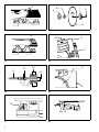
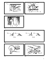
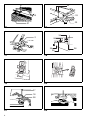
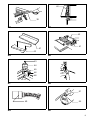
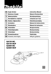
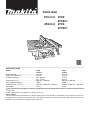
Table Saw
210 m m 2702
2702x1
255m m 2703
2703x1
SPECIFICATIONS
Model
2702
2702x1
Blade diameter .......................................... 210 mm
Hole (arbor) diameter ................................ 25 mm
Cutting capacities ...................................... 90°: 68 mm
45°: 47 mm
Table size (W x L) ..................................... 686 mm x 560 mm
No load speed (RPM) ............................... 4,600
Dimensions (L x W x H) ............................ 560 mm x 686 mm x 458 mm
Net weight ................................................. 18 kg
2703
2703x1
255 mm
25 mm
91 mm
63 mm
686 mm x 560 mm
4,600
560 mm x 686 mm x 458 mm
18 kg
Due to the continuing program of research and development, the specifications herein are subject to change without
prior notice.
Note: Specifications may differ from country to country.
Power supply
The tool should be connected only to a power supply of the same voltage as indicated on the nameplate, and can only
be operated on single-phase AC supply. They are double-insulated in accordance with European Standard and can,
therefore, also be used from sockets without earth wire.
3
5
7
4
2
1
1
8
6
2
9
10
11
12
2
1
3
4
13
6
11
15
14
17
11
12
16
5
6
18
19
7
2
8
23
9
20 21
3
22
9
24
25
10
26
27
11
90
90
45
12-A
45
12-B
12
25
30
28
13
29
14
3
32
A
B
33
29
31
15
16
34
2
30
35
17
18
19
20
37
18
38
21
4
22
36
40
39
23
24
42
41
41
42
25
26
43
44
45
46
48
47
27
28
51
49
29
50
30
5
Symbols
The followings show the symbols used for the tool. Be sure that you understand their meaning before use.
❏ Read instruction manual.
❏ DOUBLE INSULATION
6
ENGLISH
Explanation of general view
1
2
3
4
5
6
7
8
9
10
11
12
13
Offset wrench 13-22
Wrench 19
Loosen
Inner flange
Ring
Saw blade
Outer flange
Hex nut
Tighten
Blade guard
Spreader
Pressure plate
These two clearances should
be equal.
14 Blade guard mounting portion
(stay)
15 Hex bolts (A)
16 Hex bolts (B)
17
18
19
20
21
22
23
24
25
26
27
28
29
30
31
32
33
34
5 mm or less
Miter gauge
Rip fence
Lower
Raise
Handle
Lock lever
Handwheel
Arrow pointer
90° adjusting screw
45° adjusting screw
Guide rail
Grip
Fence holder
Scale
Hex bolts
Adjusting nut
Screw
SAFETY INSTRUCTIONS
Warning! When using electric tools, basic safety precautions should always be followed to reduce the
risk of fire, electric shock and personal injury, including the following. Read all these instructions before
attempting to operate this product and save these
instructions.
For safe operation:
1. Keep work area clean
Cluttered areas and benches invite injuries.
2. Consider work area environment
Don’t expose power tools to rain. Don’t use power
tools in damp or wet locations. Keep work area well
lit. Don’t use power tools in presence of flammable
liquids or gases.
3. Guard against electric shock
Prevent body contact with grounded surfaces (e.g.
pipes, radiators, ranges, refrigerators).
4. Keep children away
Do not let visitors contact tool or extension cord. All
visitors should be kept away from work area.
5. Store idle tools
When not in use, tools should be stored in dry, high,
or locked-up place, out of the reach of children.
6. Don’t force tool
It will do the job better and safer at the rate for which
it was intended.
7. Use right tool
Don’t force small tools or attachments to do the job
of a heavy duty tool. Don’t use tools for purposes not
intended; for example, don’t use circular saw for cutting tree limbs or logs.
8. Dress properly
Do not wear loose clothing or jewelry. They can be
caught in moving parts. Rubber gloves and non-skid
footwear are recommended when working outdoors.
Wear protective hair covering to contain long hair.
9. Use safety glasses and hearing protection
Also use face or dust mask if cutting operation is
dusty.
10. Connect dust extraction equipment
If devices are provided for the connection of dust
extraction and collection facilities, ensure these are
connected and properly used.
35
36
37
38
39
40
41
42
43
44
45
46
47
48
49
50
51
Scale plate
Arrow pointer
Groove
Knob
Push stick
Wood or plastic facing
Auxiliary fence
Push block
Rubber cap
Leg
Under stay
Bolt
Nut
Stay
Limit mark
Brush holder cap
Holder cap opener
11. Don’t abuse cord
Never carry tool by cord or yank it to disconnect it
from receptacle. Keep cord from heat, oil and sharp
edges.
12. Secure work
Use clamps or a vise to hold work. It’s safer than
using your hand and it frees both hands to operate
tool.
13. Don’t overreach
Keep proper footing and balance at all times.
14. Maintain tools with care
Keep tools sharp and clean for better and safer performance. Follow instructions for lubricating and
changing accessories. Inspect tool cords periodically and, if damaged, have repaired by authorized
service facility. Inspect extension cords periodically
and replace if damaged. Keep handles dry, clean
and free from oil and grease.
15. Disconnect tools
When not in use, before servicing, and when changing accessories such as blades, bits and cutters.
16. Remove adjusting keys and wrenches
Form the habit of checking to see that keys and
adjusting wrenches are removed from tool before
turning it on.
17. Avoid unintentional starting
Don’t carry plugged-in tool with finger on switch. Be
sure switch is off when plugging in.
18. Outdoor use extension cords
When tool is used outdoors, use only extension
cords intended for use outdoors and so marked.
19. Stay alert
Watch what you are doing. Use common sense. Do
not operate tool when you are tired.
7
20. Check damaged parts
Before further use of the tool, a guard or other part
that is damaged should be carefully checked to
determine that it will operate properly and perform
its intended function. Check for alignment of moving
parts, binding of moving parts, breakage of parts,
mounting, and any other conditions that may affect
its operation. A guard or other part that is damaged
should be properly repaired or replaced by an
authorized service center unless otherwise indicated
elsewhere in this instruction manual. Have defective
switches replaced by and authorized service center.
Do not use tool if switch does not turn it on and off.
21. Warning
The use of any other accessory or attachment other
than recommended in this operating instruction or
the catalog may present a risk of personal injury.
22. Have your tool repaired by an expert
This electric appliance is in accordance with the relevant safety rules. Repairing of electric appliances
may be carried out only by experts otherwise it may
cause considerable danger for the user.
8.
9.
10.
11.
12.
13.
14.
ADDITIONAL SAFETY RULES
1.
2.
3.
4.
5.
6.
7.
8
Wear eye protection.
Don’t use the tool in presence of flammable liquids or gases.
Never use the tool with an abrasive cut-off wheel
installed.
Check the blade carefully for cracks or damage
before operation. Replace cracked or damaged
blade immediately.
Clean the spindle, flanges (especially the installing surface) and hex nut before installing the
blade. Poor installation may cause vibration/
wobbling or slippage of the blade.
Use saw-blade guard and spreader for every
operation for which it can be used, including all
through sawing operations. Through sawing
operations are those in which the blade cuts
completely through the workpiece as in ripping
or cross cutting. Never use the tool with a faulty
blade guard or secure the blade guard with a
rope, string, etc. Any irregular operation of the
blade guard should be corrected immediately.
Do not cut metals such as nails and screws.
Inspect for and remove all nails, screws and
other foreign matter from the workpiece before
operation.
15.
16.
17.
18.
19.
Remove wrenches, cut-off pieces, etc. from the
table before the switch is turned on.
Never wear gloves during operation.
Keep hands out of the line of saw blade. Do not
stand or permit anyone else to stand in line with
the path of the saw blade.
Make sure the blade is not contacting the
spreader or workpiece before the switch is
turned on.
Before cutting an actual workpiece, let the tool
run for a while. Watch for vibration or wobbling
that could indicate poor installation or a poorly
balanced blade.
Use a push stick when required. Push sticks
should be used for ripping narrow workpieces to
keep your hands and fingers well away from the
blade.
Pay particular attention to instructions for reducing risk of KICKBACK. KICKBACK is the ejection
of the workpiece from the tool back towards the
operator. Avoid KICKBACKS by keeping the
blade sharp, by keeping the rip fence parallel to
the blade, by keeping the spreader, antikickback
fingers and blade guard in place and operating
properly, by not releasing the workpiece until
you have pushed it all the way past the blade,
and by not ripping a workpiece that is twisted or
warped or does not have a straight edge to guide
along the fence.
Do not perform any operation freehand. Freehand means using your hands to support or
guide the workpiece.
Never reach around or over saw blade.
Avoid abrupt, fast feeding. Feed as slowly as
possible when cutting hard workpieces. Do not
bend or twist workpiece while feeding. If you
stall or jam the blade in the workpiece, turn the
tool off immediately. Unplug the tool. Then clear
the jam.
Never remove cut-off pieces near the blade or
touch the blade guard while the blade is running.
Don’t abuse cord. Never yank cord to disconnect
from receptacle. Keep cord away from heat, oil,
water and sharp edges.
SAVE THESE INSTRUCTIONS.
OPERATING INSTRUCTIONS
The tool is shipped from the factory with the saw blade and blade guard not in the installed condition. Assemble as follows.
CAUTION:
Always unplug the tool before assembly.
Installing saw blade
CAUTION:
• Use the following saw blade. Do not use saw blades which do not comply with the characteristics specified in these
instructions.
For Model
Max. dia.
Min. dia.
Blade thickness
Kerf
2702
2702x1
210 mm
203 mm
1,4 mm or less
1,6 mm or more
2703
2703x1
260 mm
220 mm
1,8 mm or less
2 mm or more
• Check the arbor hole diameter of the blade before installing the blade. Always use the correct ring for the arbor hole
of the blade you intend to use.
Remove the table insert on the table. Hold the outer flange with the offset wrench 13-22 and loosen the hex nut with
the wrench 19. Then remove the outer flange. (Fig. 1)
Assemble the inner flange, ring, saw blade, outer flange and hex nut onto the arbor, making sure that the teeth of the
blade are pointing down at the front of the table. Always install the hex nut with its recessed side facing the outer
flange. (Fig. 2)
To secure the blade in place, hold the outer flange with the offset wrench 13-22, then tighten the hex nut with the
wrench 19. BE SURE TO TIGHTEN THE HEX NUT SECURELY. (Fig. 3)
Installing blade guard
CAUTION:
Before installing the blade guard, adjust the depth of cut
to its maximum elevation.
Insert the spreader between the blade guard mounting
portion (stay) and the pressure plate. (Fig. 4)
Tighten the hex bolts (A) with the offset wrench 13-22.
The spreader installing location is factory-adjusted so
that the blade and spreader will be in a straight line. However, if they are not in a straight line, loosen the hex bolts
(B) and adjust the blade guard mounting portion (stay) so
that the spreader is aligned directly behind the blade.
Then tighten the hex bolts (B) to secure the stay. (Fig. 5)
CAUTION:
• Always grasp the striped portion of the offset wrench
when tightening the hex bolts. If you tighten the hex
bolts while grasping the offset wrench further than the
striped portion, the hex bolts may be damaged and/or
an injury to your hand may result.
• If the blade and spreader are not aligned properly, a
dangerous pinching condition may result during operation. Make sure they are properly aligned.
There must be a clearance of 5 mm or less between the
spreader and the blade teeth. Adjust the spreader
accordingly and tighten the hex bolts (A) securely.
(Fig. 6)
Attach the table insert on the table, then check to see
that the blade guard works smooth.
Positioning table saw
Locate the table saw in a well lit and level area where you
can maintain good footing and balance. It should be
installed in an area that leaves enough room to easily
handle the size of your workpieces.
The table saw should be secured with four screws or
bolts to the work bench or table saw stand using the
holes provided in the bottom of the table saw. When
securing the table saw on the work bench, make sure
that there is an opening in the top of the work bench the
same size as the opening in the bottom of the table saw
so the sawdust can drop through. If during operation
there is any tendency for the table saw to tip over, slide or
move, the work bench or table saw stand should be
secured to the floor.
NOTE:
Table saw stand Model 2702x1/2703x1 are standardequipped with a table saw stand. Leave more than
300 mm clearance between the table and a wall to allow
chip ejection.
Storing accessory (Fig. 7 & 8)
The miter gauge and wrenches can be stored on the left
side of the base and the rip fence can be stored at the
rear of the base.
Adjusting depth of cut (Fig. 9)
The depth of cut may be adjusted by turning the handle.
Turn the handle clockwise to raise the blade or counterclockwise to lower it.
Adjusting bevel angle (Fig. 10)
Loosen the lock lever and turn the handwheel until the
desired angle (0° – 45°) is obtained. The bevel angle is
indicated by the arrow pointer. After obtaining the desired
angle, tighten the lock lever to secure the adjustment.
9
Adjusting positive stops
The tool is equipped with positive stops at 90° and 45° to
the table surface. To check and adjust the positive stops,
proceed as follows:
Move the handwheel as far as possible by turning it.
Place a triangular rule on the table and check to see if
the blade is at 90° or 45° to the table surface. (Fig. 11)
If the blade is at an angle shown in Fig. 12-A, turn the
adjusting screws clockwise; if it is at an angle shown in
Fig. 12-B, turn the adjusting screws counterclockwise to
adjust the positive stops. (Fig. 12)
After adjusting the positive stops, set the blade at 90° to
the table surface. Then adjust the arrow pointer so that its
right edge is aligned to the 0° graduation. (Fig. 13)
Installing and adjusting rip fence
Raise the grip of the rip fence. Install the rip fence on the
table so that the fence holder engages with the guide rail.
The rip fence can be secured by lowering the grip.
(Fig. 14)
To check to be sure that the rip fence is parallel with the
blade, secure the rip fence 2 – 3 mm from the blade.
Raise the blade up to maximum elevation. Mark one of
the blade teeth with a crayon. Measure the distance (A)
and (B) between the rip fence and blade. Take both measurements using the tooth marked with the crayon.
These two measurements should be identical. (Fig. 15)
If the rip fence is not parallel with the blade, proceed as
follows:
1. Turn the adjusting nut counterclockwise a couple of
turns. (Fig. 16)
2. Loosen the two hex bolts on the rip fence with the
wrench provided. (Fig. 17)
3. Adjust the rip fence until it becomes parallel with the
blade.
4. Lower the grip to secure the rip fence.
5. Tighten the two hex bolts on the rip fence.
6.
CAUTION:
• Always grasp the striped portion of the wrench
when tightening the hex bolts. If you tighten the
hex bolts while grasping the wrench further than
the striped portion, the hex bolts may be damaged
and/or an injury to your hand may result.
• Be sure to adjust the rip fence parallel with the
blade, or a dangerous kickback condition may
occur.
With the grip of the rip fence lowered, turn the
adjusting nut clockwise to secure the rear end of the
rip fence. Do not turn the adjusting nut clockwise
excessively. You may have some difficulty adjusting
the rip fence parallel with the saw blade when repositioning the rip fence.
Bring the rip fence up flush against the side of the blade.
Make sure that the arrow pointer on the fence holder
points to the 0° graduation. If the arrow pointer does not
point to the 0° graduation, loosen the screw on the scale
plate and adjust the scale plate. (Fig. 18)
Switch action (Fig. 19 & 20)
To start the tool, depress the “ON” button. To stop the
tool, depress the “OFF” button. When depressing the button, it is convenient to view it through the window area in
the table.
10
Operation
CAUTION:
• Always use “work helpers” such as push sticks and
push blocks when there is a danger that your hands or
fingers will come close to the blade.
• Always hold the workpiece firmly. Do not bend or twist it
while feeding. If the workpiece is bent or twisted, dangerous kickbacks may occur.
• Never withdraw the workpiece while the blade is running. If you must withdraw the workpiece before completing a cut, first switch the tool off while holding the
workpiece firmly. Wait until the blade has come to a
complete stop before withdrawing the workpiece. Failure to do so may cause dangerous kickbacks.
• Never remove cut-off material while the blade is running.
• Never place your hands or fingers in the path of the
saw blade. Be especially careful with bevel cuts.
• Always secure the rip fence firmly, or dangerous kickbacks may occur.
• Always use “work helpers” such as push sticks and
push blocks when cutting small or narrow workpieces,
or when the blade is hidden from view while cutting.
Place the workpiece on the table. Switch the tool on without the blade making any contact. Hold the workpiece
firmly with both hands and wait until the blade attains full
speed. Then gently feed the workpiece into the blade.
When cutting hard workpieces, feed them as slowly as
possible. To get clean cuts, feed the workpiece straight
and at a uniform speed.
CAUTION:
• Avoid abrupt, fast feeding. Failure to do so may cause
overload of the motor, resulting in malfunction of the
tool.
• Always make sure that the blade guard operates properly to cover the blade before operation.
• When cutting thin workpieces, adjust the cut of depth a
bit higher than the thickness of the workpiece to obtain
a cleaner cut.
Crosscutting
CAUTION:
• When making a crosscut, remove the rip fence from the
table.
• When cutting long or large workpieces, always provide
adequate support to the sides of the table. The support
should be at the same height as the table.
Miter gauge (Fig. 21)
Use the miter gauge when cutting relatively wide workpieces at an angle.
Slide the miter gauge into the thick grooves in the table.
Loosen the knob on the gauge and align to desired angle
(0° to 60°). Bring stock flush up against fence and feed
gently forward into the blade.
CAUTION:
Avoid creep of workpiece and gauge by firm workholding
arrangement, especially when cutting at an angle.
(Fig. 22)
Ripping
MAINTENANCE
CAUTION:
• When ripping, remove the miter gauge from the table.
• When cutting long or large workpieces, always provide
adequate support behind the table. The support should
be at the same height as the table.
CAUTION:
Always be sure that the tool is switched off and
unplugged before carrying out any work on the tool.
Switch the tool on and gently feed the workpiece into the
blade along with the rip fence. Always use a push stick
when there is a danger that your hands or fingers will
come close to the blade. (Fig. 23)
A facing should be used for operations when the blade
comes close to the rip fence. Make a facing from wood
board or plastic board. Fasten it to the rip fence with bolts
and nuts or glue. (Fig. 24)
When the push stick strikes the blade guard because the
space between the blade and the rip fence is too narrow,
use an auxiliary fence and push block shown in Fig. 25.
Clamp the auxiliary fence to the rip fence in two locations. Gently feed the workpiece along the auxiliary
fence. When your hand comes close to the blade, rest
the push block on the auxiliary fence and feed through
until cut is completed. (Fig. 26)
Table saw stand
NOTE:
The following is description only for the tools equipped
with a table saw stand. For table saw stands as optional
accessories, refer to the instruction manuals for table
saw stands provided with them.
Place the stays on a level location and assemble the legs
inside. Secure with the bolts and nuts, then attach the
rubber caps to the ends of the legs. (Fig. 27)
Now set the table saw on top of the assembled stand and
secure with four hex bolts, washers and hex nuts.
(Fig. 28)
CAUTION:
This is a special stand built precisely for this Makita table
saw. Do not use it for other type tools.
NOTE:
Model 2702x1/2703x1 are standard-equipped with a
table saw stand.
Inspection
• Periodically check tightness of screws carefully.
• Make sure that the blade guard operates smooth and
properly before operation.
Storage
Always unplug the tool after operation. Store it in dry, and
locked-up place — out of reach of children. When not
using it for a long period, take measures to prevent dust
and rust.
Cleaning
Clean out sawdust and chips from time to time. Carefully
clean the blade guard and moving parts inside the table
saw.
Lubrication
To keep the table saw in tip-top running condition, and to
assure maximum service life, oil or grease the moving
parts and rotating parts from time to time.
Lubrication places:
• Threaded shaft to elevate the blade
• Hinge to rotate the frame
• Elevation guide shafts on motor
• Gear to elevate the blade
• Gear to bevel the blade
• Shaft to rotate the blade guard
• Around slot in steel plate to secure bevel adjustment
• Cam shaft of rip fence
Replacement of carbon brushes (Fig. 29 & 30)
Replace carbon brushes when they are worn down to the
limit mark. Both identical carbon brushes should be
replaced at the same time.
To maintain product safety and reliability, repairs, maintenance or adjustment should be carried out by a Makita
Authorized Service Center.
ACCESSORIES
CAUTION:
These accessories or attachments are recommended for
use with your Makita tool specified in this manual. The
use of any other accessories or attachments might
present a risk of injury to persons. Only use accessory or
attachment for its stated purpose.
If you need any assistance for more details regarding
these accessories, ask your local Makita service center.
•
•
•
•
•
•
•
•
•
Steel & Carbide-tipped saw blades
Sub table set (Left/Right)
Rip fence
Miter gauge
Offset wrench 13-22
Wrench 19
Holder cap opener
Joint ( for connecting to dust collector )
Stand set
11
Makita Corporation
Anjo, Aichi, Japan
884129B8