1
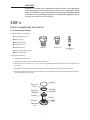
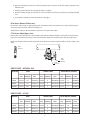
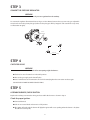
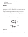
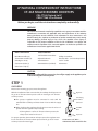
LP/NATURAL CONVERSION KIT INSTRUCTIONS
CT-365 SEALED BURNER COOKTOPS
CKL-CT365 Natural to LP
CKN-CT365 LP to Natural
Before you begin, read these instructions completely and carefully.
WARNING
This conversion kit must be installed by a qualified service agency in accordance with the
manufacturer’s instructions. All applicable codes and requirements of the authority
having jurisdiction must be followed. If the information in these instructions is not
followed exactly, fire, explosion or production of carbon monoxide may result, causing
property damage, personal injury or loss of life. The qualified service agency is
responsible for the proper installation of this kit. The installation is not proper and
complete until the operation of the converted appliance is checked as specified in the
manufacturer’s instructions supplied with the kit.
PARTS INCLUDED
TOOLS NEEDED
Main Burner Orifice (5)
1/8" Flat-blade Screwdriver
Phillips Screwdriver
Simmer Burner Orifice (5)
Adjustable Wrench
Ratchet with 1-1/16" Hex Deep Socket
Valve Bypass Jet (5)
7mm Nut Driver
25/32" Socket
Conversion Sticker (1)
4mm Nut Driver (included)
Manometer
Valve Stem C-Clip (5)
CAUTION:
Before proceeding with the conversion, shut-off gas supply to the appliance prior
to disconnecting the electrical power.
STEP 1
GAS SUPPLY
Measure the incoming gas pressure to the regulator.
With the installation of this conversion kit, the cooktop should operate on
LP gas at 10" of water column pressure and on natural gas at 4" of water
column pressure.
The pressure regulator must be connected in series with the
manifold of the cooktop and must remain in series with the supply
line.
When checking the regulator, the inlet pressure must be at least 1"
greater than the regulator output setting.
– If the regulator is set for 10" of water column pressure, the
inlet pressure must be at least 11".
For proper operation, the maximum inlet pressure to the regulator must
be no more than 14" of water column pressure for LP gas and 9" water
column pressure for natural gas.
1
Regulator
Solid Piping
or Flexible
Connector
Shut-Off
Valve
Pipe Stub
Connection: 1/2" N.P.T. minimum 5/8" dia. metal flex line.
IMPORTANT:
Disconnect the cooktop and the individual shut-off valve from the gas supply piping
system during any pressure testing of that system at test pressures greater than 1/2 psig.
Isolate the cooktop from the gas supply piping system by closing the individual manual
shut-off valve to the cooktop during any pressure testing of the gas supply piping system
at test pressures equal to or less than 1/2 psig.
STEP 2
REPLACE ALL BURNER AND VALVE ORIFICES
A. To Remove the Cooktop
Cooktop removal is required for:
Gas piping inspection
Wiring service
Valve replacement
Jet holder service
Manifold service
Main Jet
Simmer Jet
Indicator light replacement
Valve Bypass
Jet
Bezel replacement
To remove the cooktop:
1. Remove the valve knobs.
2. Remove the burner caps and main burner head (brass).
3. Remove the brass nut using a 1-1/16" socket or adjustable wrench and lift the burner ring from the
assembly.
4. Remove the large brass orifice tube from the center of each burner base using a 25/32" socket.
5. Lift each burner base and disconnect the push-on wire terminal from the spark electrode. Place the burner
base assemblies in a safe place.
Burner Cap
Burner Head
(Brass)
Burner Ring
Locking Nut
Burner Ring
(Aluminum)
Locator Pin
Electrode
Main Orifice
Burner Base
7mm
Simmer Orifice
4mm
2
6. Raise the cooktop front about 6" and disconnect the 6 pin connector under the cooktop adjacent to the
left front valve.
7. Push the spark electrode wire through the holes in cooktop.
8. Pick the cooktop straight up and place in a safe area where it will not be scratched or accidently knocked
over.
9. To install the cooktop, reverse the procedure 1 through 8.
B. To Access Burner Orifices/Jets:
Unscrew the orifice using an appropriately sized conventional socket or nut driver. Use a piece of sticky tape in
socket to prevent the loose orifice from falling out.
Verify that the orifices in the kit match the chart sizes and replace the orifices.
C. To Access Valve Bypass Jets:
Remove the c-clips that retain the valve switches and slide the switches off of the valve shafts. Locate the valve
bypass jet in the valve body. Using a small 1/8" flat-blade screwdriver, carefully remove the valve bypass jets.
Replace each orifice with the marked orifice from the kit. Ensure that the replaced orifice is firmly seated in the
valve.
Valve
Orifice
VALVE
BYPASS JET
VALVE
BYPASS JET
VALVE
SWITCH
(REMOVE)
ORIFICE SIZES – NATURAL GAS
LOCATION
MAIN
SIMMER (LOW)
SIZE
MARKING
RATE
SIZE
MARKING
REAR
1.51mm
151
11K Btu/hr 0.57mm
P
FRONT
1.51mm
151
11K Btu/hr 0.57mm
CENTER
2.0mm
200
17.5K Btu/hr 0.57mm
VALVE ORIFICE (SIMMER)
RATE
SIZE
MARKING
RATE
3000 Btu/hr 0.71mm
71
1200 Btu/hr
P
3000 Btu/hr 0.71mm
71
1200 Btu/hr
P
3000 Btu/hr 0.71mm
71
1200 Btu/hr
ORIFICE SIZES – LP GAS
LOCATION
MAIN
SIMMER (LOW)
SIZE
MARKING
RATE
SIZE
MARKING
REAR
0.89mm
89
10K Btu/hr 0.37mm
G
FRONT
0.89mm
89
10K Btu/hr 0.37mm
CENTER
1.10mm
110
15K Btu/hr 0.37mm
3
VALVE ORIFICE (SIMMER)
RATE
SIZE
MARKING
RATE
3000 Btu/hr 0.45mm
45
1200 Btu/hr
G
3000 Btu/hr 0.45mm
45
1200 Btu/hr
G
3000 Btu/hr 0.45mm
45
1200 Btu/hr
STEP 3
CONVERT THE PRESSURE REGULATOR
WARNING
Do not remove the pressure regulator from the cooktop.
To convert the regulator from Natural Gas to LP gas or LP to Natural, remove the cap screw using an adjustable
wrench and reverse the plastic plunger (make sure the plunger is firmly “swapped” and seated in the cap screw,
see illustration to right).
Reverse
Plastic Plunger
LP
NAT
LP
NAT
Cap Screw
STEP 4
CHECK FOR LEAKS
WARNING
Check for leaks before attempting to light the burners.
Check to be sure all controls are in the OFF position.
Turn on the gas supply at the shut-off valve.
Use a leak detector at all connections. If a leak is detected, tighten the connection and test again.
DO NOT USE A FLAME TO CHECK FOR GAS LEAKS.
STEP 5
ASSEMBLE BURNERS, CHECK IGNITION
Replace the cooktop, reconnect the wiring and reassemble the burners as shown in Step 2.
Check for proper ignition:
Connect Electrical.
Push in one control knob and turn 90° to “HI” position.
The igniter will spark and the burner will light; the igniter will cease sparking when the burner is lit. (Note
that all burners will spark.)
4
The first test may require some time while air is flushed out of the gas line.
Turn knob to “OFF”.
Repeat the procedure for each burner.
STEP 6
CHECK FLAME QUALITY
Check for proper burner flame characteristics (see illustrations).
Burner flames should be blue and stable. Some yellow tipping may be normal on LP Gas. The flame should not
have excessive noise or lifting of the flame from the burner.
Due to differences in gas characteristics and burner usage (i.e. gas pressure, cleanliness, etc.), burners may
perform differently.
Burner Operation
Two flames are used on all five burners. These dual flame burners have an upper ring of main burner ports
which produce the main flame for high heat cooking from the “HI” knob setting to the “LO” knob setting.
The bottom simmer flame is used for simmer heat cooking operations such as melting chocolate, holding food at
serving temperature and simmering. Both flames are lit when the knob is between “HI” and “LO”. Only the simmer
flame is lit when the knob is in the “SIM” position.
Burner Adjustment
There is no air shutter adjustment, etc. on this burner.
The only adjustment available is to clean the burners and clean or replace orifices.
Burner Cap
High to Low
Flame
Simmer Flame
Simmer Ring
Simmer Flame
Main Burner Ports
STEP 7
COMPLETE AND ADHERE CONVERSION STICKER TO THE COOKTOP BOTTOM SURFACE
Complete the required information on the Conversion Sticker and adhere to the bottom of the unit next to Rating
Plate Sticker. The Conversion sticker MUST reflect the change in fuel.
5
CONVERSION STICKER SAMPLES
A. From Natural Gas to LP
B. From LP to Natural Gas
THIS CONVERSION RATING LABEL RELATES TO THE FOLLOWING
DCS MODELS:
CT-365
THIS CONVERSION RATING LABEL RELATES TO THE FOLLOWING
DCS MODELS:
CT-365
SUPPLY PRESSURE - MINIMUM 11" W.C.
MAXIMUM 14" W.C.
SUPPLY PRESSURE - MINIMUM 6" W.C.
MAXIMUM 9" W.C.
MANIFOLD PRESSURE - 10" W.C.
MANIFOLD PRESSURE - 4" W.C.
INPUT RATINGS - CENTER - 15,000 BTU/HR
FRONT - 10,000 BTU/HR
REAR - 10,000 BTU/HR
INPUT RATINGS - CENTER - 17,500 BTU/HR
FRONT - 11,000 BTU/HR
REAR - 11,000 BTU/HR
CONVERSION KIT PART. CKL-CT365
CONVERSION KIT PART. CKN-CT365
THIS APPLIANCE HAS BEEN CONVERTED ON
FROM NATURAL GAS TO LP GAS WITH CONVERSION KIT
PART NO. CKL-CT365
THIS APPLIANCE HAS BEEN CONVERTED ON
FROM LP GAS TO NATURAL GAS WITH CONVERSION KIT
PART NO. CKN-CT365
Name and address of qualified installer or service organization
Name and address of qualified installer or service organization
WHO ACCEPTS RESPONSIBILTITY FOR THE CORRECTNESS OF THE
CONVERSION
WHO ACCEPTS RESPONSIBILTITY FOR THE CORRECTNESS OF THE
CONVERSION
6
NOTES
7
5800 Skylab Road, Huntington Beach, CA 92647
Tel: (714) 372-7000 Fax: (714) 372-7001
Customer Service: (888) 281-5698
www.dcsappliances.com
As product improvement is an ongoing process at DCS, we
reserve the right to change specifications or design
without notice.
P/N 17617 Rev. B
03/03