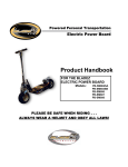
1
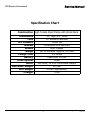
Service Manual
PB-SM804SA,SM804SB
PB-SM806,SM807,SM808
TPB-450EX
Date 03-31-03
Revison 002
Electric PowerBoard
ISM, Inc. • 1028 4th Street SW • Auburn, WA 98001 • Phone: (253) 333-1200 • Fax: (253) 333-1212
www.tanaka-usa.com
[email protected]
Service Manual
XTR Electric Powerboard
Table of Contents
Specifications
2
Troubleshooting
3
Safety & Shop Practices
4
Routine Maintenance
4
Tools
5
Brake System
6
Wheel Removal
7-8
Steering Head Components
9-12
Chain Maintenance
13
Deck Removal
14
Electric Drive Components
15-16
Circuit Breaker
16
Cables / Controls
17-18
Batteries
19
Electric Drive Motor
20
Warranty Statement
21
www.tanaka-usa.com
1
[email protected]
Revison 002
Service Manual
XTR Electric Powerboard
Specification Chart
Construction High Tensile Steel Frame with Wood Deck
Dimensions
Tires
Tire Pressure
Wheels
Brakes
Range
Charge Time
Battery
Drive System
Motor
Max Rider Weight
Unit Weight
Charger
www.tanaka-usa.com
40” High, 9.5” Wide
10” Kenda Pneumatic
50-60 psi
Composite Core Split Rim
Disc, Caliper
60-75 Minutes, Approx. 12 Miles
4-5 Hours
Lead Acid, 24 Volt
Chain
450 Watt, 24 Volt Continuous Output
270 lbs.
55 lbs. (approximately)
2 AH
2
[email protected]
Revison 002
Service Manual
XTR Electric Powerboard
Trouble Shooting
The following guide will help provide a logical sequence to quickly identify problematic areas of the
PowerBoard to facilitate repair. Always bear in mind that the majority of electrical symptoms are
actually the result of a problem with the chassis of the unit.
Before beginning the troubleshooting of the electrical system, inspect the following:
1. Tires - Make sure they are properly inflated. Check manufacture’s recommended tire pressure
listed on the side of the tire.
2. Wheels – Make sure that the wheel bearings are freely turning, and that neither the front or
rear wheel is making contact with the chassis as to prevent it from easily rotating.
3. Final Drive – check to ensure that the chain is properly adjusted and not excessively worn.
Sprockets should also be inspected, (see page 10).
Any factor that creates friction or drag to the chassis will result in lack-luster performance that can
appear to be electrical. Other issues that can present themselves as electrical problems are operator
usage. If the unit is used in very hilly areas, in excessive temperatures, or with an individual who is
very heavy – then the battery capacity will be depleted much faster than in normal operating
conditions.
PowerBoard will not go:
•
•
•
•
•
•
•
Charge for twelve hours and re-try.
Still no good - Unit may have popped the circuit breaker. Allow unit to cool completely,
re-set the breaker by raising and lowering the kick-stand, (or with newer models turning
power switch off/on/off/on.)
Still no good - test batteries and charger.
Still no good - test throttle wire.
Still no good - test brake lever.
Still no good - test electric motor.
Still no good - replace circuit board.
PowerBoard will not go fast:
•
•
•
•
•
Charge for twelve hours and re-try.
Still no good - test batteries and charger.
Still no good - test throttle wire, (NOTE: Only models with variable speed).
Still no good - test electric motor.
Still no good - replace circuit board.
PowerBoard will not go far:
•
•
•
Charge for twelve hours and re-try.
Still no good - test batteries and charger.
Still no good - replace circuit board.
www.tanaka-usa.com
3
[email protected]
Revison 002
Service Manual
XTR Electric Powerboard
Safety & Shop Practices
The most successful and profitable service shops consistently seem to maintain the best habits of safety,
cleanliness, and orderly procedure. The following information is intended as a guide towards developing
habits that are necessary to accomplish satisfactory service work.
o
Maintain a clean and orderly work area that is well lighted and adequately ventilated.
o
Tools, instruments, and parts needed for work should be clean and readily available before any job is
started. (Special tools available for servicing TANAKA equipment are listed in this manual.)
o
Scooter should be cleaned before repair work starts. Cleaning will often help reveal a source of
trouble.
o
Before attempting to repair or operate any equipment, read and understand all information provided by
the instruction manual for the equipment.
o
Never attempt to service a unit that is running, or still heated from running, unless it is specifically
required by the manufacturer’s instructions.
o
Wipe-up all spilled liquids immediately. Use non-flammable solvents for cleaning. Clean all parts
before reconditioning or reassembling.
o
Thoroughly inspect all parts for wear or damage. Replace all parts that show damage or excessive
wear.
o
Always recondition and/or repair equipment strictly according to the Manufacturer’s specifications.
o
Be sure all shields and safety devices are correctly installed before performing any final operating tests.
o
After completion of any service or repair, the equipment should be thoroughly cleaned.
Routine Maintenance Guide
Daily
www.tanaka-usa.com
All Fasteners
Tighten
O
Chain / Sprockets
Inspect/Adjust
O
Brake (front)
Inspect/Adjust
Steering Head
Inspect/Adjust
Batteries
Charge
4
Weekly
Monthly
O
O
O
[email protected]
Revison 002
Service Manual
XTR Electric Powerboard
Tools
The following is a minimum list of tools required to service the XTR-S Electric
PowerBoard. Other tools may be preferable; however, complete service can be
performed with the tools indicated below:
Test Wire (Part No. 30985)
This is a switch that is also a replacement
part on some models of XTR-S
PowerBoards. It plugs into the circuit
board and serves as a special tool in
diagnosing problematic functions.
Screwdrivers – Slot/Phillips
Jumper Wire Set
(Part No. 31655)
This is a wire that can be used to
test batteries on units with batery
leads permanately attached to
the controller board.
(see page 18)
Mallet
Wrenches – 8,10,13,17mm
www.tanaka-usa.com
Electrical Multi-Tester
(Digital Type)
Head Wrench (Part No. 31254)
Long Handle Allen Wrenches – 3,4,5,6mm
5
[email protected]
Revison 002
Service Manual
XTR Electric Powerboard
Brake Adjustment
Figure 1
Figure 2
Two adjustments can be made to the brake system. First, use the adjustment located on the caliper, near the
wheel (Fig. 1). Begin by loosening the lock-nut with an 8mm wrench, and then turn the adjuster out (counterclockwise) (Fig. 2). Once adjusted, tighten the lock nut to hold that position.
Make sure the brake caliper is not loose. Conversely, over-tightening will not allow the wheel to turn. Full
braking action should occur with approximately one-third to two-thirds throw of the brake lever.
Figure 3
Figure 4
The design of the brake lever (mounted on the handlebar), provides another type of adjustment to the brake
cable. Simply loosen the lock nut, and turn the adjuster out (counter clock-wise), until the desired adjustment is
reached, then re-tighten the lock nut (Fig. 3).
When neither of these adjustments allows an acceptable amount of braking action, it’s an indication that the
brake pads may be worn beyond their service limits and or the cable has stretched. In either case, spares
should be installed.
Brake pads are simply slid into place (Fig. 4), but it requires that tension be taken off of the cable to allow the
new pads to be fitted. Note that the pads are not identical, and it is necessary to match the pad with the
appropriate brake actuator arm.
www.tanaka-usa.com
6
[email protected]
Revison 002
Service Manual
XTR Electric Powerboard
Wheel Removal - Front Wheel
Figure 5
Figure 6
The front wheel is held in place with a solid axle, and can be removed with two 17mm wrenches and/or
sockets. Remove the locking nut from one side of the wheel, and gently tap the axle through the wheel. This
will free the wheel assembly from the frame. (Fig. 5)
To disassemble the wheel for servicing the tire and/or tube, you must first remove the brake disc. Removal
requires a 4mm hex wrench. Note that each of the four bolts use spacers between the disc and the wheel.
With the disc removed, it is possible to access the four bolts and nuts that secure the two halves of the wheel
assembly together. (Fig. 6) The hardware securing the two wheel halves will require a 13mm wrench or
socket and a 6mm hex wrench.
CAUTION: Be sure to deflate the tire prior to attempting to disassemble the two wheel
halves. Tire and components can cause serious injury if you attempt to separate while inflated.
With the wheel disassembled, it is advisable to check the integrity of the two ball bearings that ride within the
hub of the wheel. If they feel worn or do not turn freely, replace them.
Upon re-assembly, ensure that the three axle spacers are properly positioned.
www.tanaka-usa.com
7
[email protected]
Revison 002
Service Manual
XTR Electric Powerboard
Wheel Removal – Rear Wheel
NOTE: Extreme caution should be used when servicing the drive chain or rear wheel. Service or maintenance
involving the chain should ONLY be performed when power to the electric motor has been disconnected from
the battery.
Figure 7
Figure 8
Begin by removing the axle lock-nut with a 17mm wrench or socket. Gently tap the axle through the wheel.
This will allow the rear wheel assembly to be slid forward far enough to remove the chain from the rear
sprocket. With the chain removed the entire rear wheel can be separated from the PowerBoard.
To disassemble the wheel, begin by removing the rear drive sprocket, which is attached with four hex-hole
screws on newer models, and is threaded to the hub on earlier versions. Next, remove the four large allen
head bolts. The hardware securing the two wheel halves will require a 6mm hex wrench.
CAUTION: Be sure to deflate the tire prior to attempting to disassemble the two wheel
halves. Tire and components can cause serious injury if you attempt to separate while inflated.
With the wheel disassembled (Fig. 8), it is advisable to check the integrity of the two ball bearings that ride
within the hub of the wheel. If they feel worn or do not turn freely, replace them.
Upon re-assembly, ensure that the three axle spacers are properly positioned.
www.tanaka-usa.com
8
[email protected]
Revison 002
Service Manual
XTR Electric Powerboard
Steering Head Components / Rigid Fork Model
Figure 9
Figure 10
Disassembly:
First, remove the two bolts, four spacers and lock nuts that secure the forks to the steering head. This requires either a
5mm or 6mm hex wrench, and a 13mm wrench or socket. Remove the lock nuts on the bolts, and gently tap them
through the steering head assembly (Fig. 9). Use caution not to damage the threads as you remove the bolts. With the
entire front wheel and forks removed (Fig. 10), the steering head can now be disassembled.
www.tanaka-usa.com
9
[email protected]
Revison 002
Service Manual
XTR Electric Powerboard
Steering Head Components / Rigid Fork Model cont.
Figure 11
Figure 12
Slide the upper cap up the handlebar stem, and out of the way. Remove the lower cap. Removal of these caps reveals
the large, 40mm nuts that secure the steering head assembly from the top and bottom. It is not necessary to remove the
large top nut. The steering head is held in place by two bottom 40mm nuts. One is intended to provide adjustment, and
is closest to the steering head, and the one directly beneath it is a jamb nut to ensure they do not come loose in
operation.
With these bottom nuts removed, remove the lower bearing and spacer. This will enable the entire down-tube, with the
upper bearing, to be slid out the top of the steering head. It will be necessary to fold the front steering handle to the
down position (Fig. 11) to allow enough slack in the control cables for the steering stem to be lifted from the steering
head.
Take the opportunity to thoroughly clean all parts with cleaning solvent, and inspect bearings. If they feel worn or do not
turn freely, replace them. Re-grease the bearings and carefully re-assemble.
www.tanaka-usa.com
10
[email protected]
Revison 002
Service Manual
XTR Electric Powerboard
Steering Head Components / Suspension Fork Model
Note: The suspension forks used on the XTR-S models are designed to accommodate a wide range of riders
and terrain and are NOT adjustable.
WARNING: Never attempt to disassemble the lower fork tubes. They contain a factory installed spring
under considerable tension. Disassembling the forks will release the spring and cause serious injury or
death.
Figure 13
Figure 14
Front end disassembly:
Begin by separating the top steering stem from the fork assembly by removing the three hex bolts that secure
the clamp bracket around the stem, (fig. 13), followed by removal of the locking nut, (fig. 14).
www.tanaka-usa.com
11
[email protected]
Revison 002
Service Manual
XTR Electric Powerboard
Steering Head Components / Suspension Fork Model
Figure 15
Figure 16
Next, remove the three pinch bolts that attach the upper and triple clamp supports to the fork tubes and the
steering head, (fig. 15), followed by removal of the bearing adjustment nut, (fig.16).
With these components removed, the fork unit can be removed from the steering head through the bottom.
Note: If it is not necessary to service the brake or wheel components, they can remain attached to the lower
triple clamp support and fork tubes, while servicing the steering head components.
Take the opportunity to thoroughly clean all parts with cleaning solvent, and inspect bearings. If they feel
worn or do not turn freely, replace them. Re-grease the bearings and carefully re-assemble.
www.tanaka-usa.com
12
[email protected]
Revison 002
Service Manual
XTR Electric Powerboard
Chain Maintenance
Figure 16
Figure 17
The XTR uses a number 25 drive chain to supply power to the rear wheel. (Fig. 16)
Extreme caution should be used when servicing the drive chain. Service or maintenance to the chain should
ONLY be performed when power to the electric motor has been disconnected from the battery.
The chain should be lubricated at regular intervals. Applying a commercially available chain lube, such as WHITE
LIGHTNING, after every re-charge of the batteries is ideal. Follow the directions provided by the chain lube
manufacturer. (Fig. 17)
Figure 18
To adjust the chain tension, begin by checking the slack in the
upper drive chain run midway between the sprockets (see
figure 18). Drive chain slack should be adjusted to allow ½” of
vertical movement by hand. If the chain is slack in only certain
areas, then some links are kinked and binding. This can
frequently be eliminated with lubrication.
Wear on sprockets is illustrated in Fig.19. If sprocket teeth
show signs of hooking, or wearing on the teeth, they should
be replaced.
A worn sprocket will quickly damage a new chain and viceversa. Chains and sprockets should be replaced as a set.
Figure 19
www.tanaka-usa.com
13
[email protected]
Revison 002
Service Manual
XTR Electric Powerboard
Deck Removal
Figure 20
The XTR deck is secured to the frame with 10 bolts, (standard wood version – aluminium billet decks have less
fasteners), requiring a 4mm hex wrench and a 10mm open-end wrench. Some of these bolts are secured on
the bottom side with locking nuts, and some of the bolts are simply threaded into the frame itself. For those
bolts secured with nuts on the underside, remove the nuts prior to attempting to remove the bolts from the
top.
Additionally, some of the mounting bolts may be covered by grip tape, and access to them will require the
removal of the grip tape.
Inspect the board for any damage and replace as necessary. When re-installing a deck, always ensure that all
fasteners are used, and that an adequate amount of grip tape is re-applied to ensure sound footing when in
operation.
www.tanaka-usa.com
14
[email protected]
Revison 002
Service Manual
XTR Electric Powerboard
Electric Drive Components
The following section will help to identify the components, and conduct tests to identify problems within the
electrical system.
General System Description
The XTR electric PowerBoards use two 12 Volt batteries in tandem to supply current to a 450 Watt continuous
electric motor, (300 Watts on the earliest version).
Figure 21
Figure 22
Figure 22A
Power is managed by a CPU controller board mounted to the front of the battery compartment, (Fig. 21).
High tension leads connect the system to a circuit breaker to protect the controller board from overload. The
XTR PowerBoards have used several different versions of circuit boards to accommodate slight differences in
the features and placement of components. Before ordering circuit boards as spare parts, be sure to identify
the number on the actual circuit board as it will be necessary to ensure ordering the correct part, (Fig. 22).
Newer models utilize a controller board mounted inside a sealed case. This helps prevent contamination from
dirt and moisture. (Fig. 22A)
www.tanaka-usa.com
15
[email protected]
Revison 002
Service Manual
XTR Electric Powerboard
General System Description (cont.)
Functions controlled by the circuit board include the charger, the throttle lever, the brake lever, and on some
models, the kickstand, indicator light and on/off switch.
Circuit Breaker
Figure 23
Figure 24
Figure 25
The circuit breaker is attached to the batteries only. It is intended to shut off power to the system in the event
the motor is overloaded. This can be the result of several different factors. For example, the weight capacity of
the unit has been exceeded, the unit is run in excessively hot temperature or the operator attempts to climb a
hill beyond the units ability. If any of these cause the circuit breaker to trip, two things will need to happen for
the unit to function again. The unit must have sufficient time to cool, and the breaker will need to be reset.
The breaker is reset on earlier models with the kick-stand. When the stand is down, it trips a switch on the
circuit board, (see fig. 23). Moving the stand up/down/up will reset the breaker. On newer models, turning the
on/off switch on/off/on will reset the breaker, (see fig.’s 24 and 25).
www.tanaka-usa.com
16
[email protected]
Revison 002
Service Manual
XTR Electric Powerboard
Cables / Controls
On the XTR PowerBoard, the front disc brake and throttle are cable actuated. Cables should be periodically
inspected to ensure that they move smoothly, and offer full range of motion in order to maximize braking
ability and full range of throttle. Cables that have been kinked, corroded, frayed or worn significantly should be
replaced.
Brake
Figure 26
Figure 27
The brake lever mounted to the handlebar actuates the
front disc brake. Refer to page 6 for service and
adjustments to the mechanical front brake system. The
brake lever interfaces with the wiring harness of the unit
in one respect; the lever contains a wire routed to the
circuit board that shuts down power to the electric motor
for safety. In other words, the throttle and brake cannot
be operated simultaneously. A malfunction of the brake
safety switch will allow the unit to continue to drive the
rear wheel with the brake lever activated. This can pose a
hazardous condition and should be repaired before any
further use of the PowerBoard. A defect in the system
could indicate a problem with the lever and it’s wire, or a
problem within the circuit board. Testing is done by
bypassing the switch to verify if the problem is within the
circuit board, or within the lever and it’s wire.
To test the safety shut off switch you’ll first need to
remove the deck from the frame. Next, identify the wire
going from the brake lever to the controller board, (see
fig. 26). The wire mates to the circuit board via a small
plug-in connector. Remove the plug from the board, and
attach the test switch (part #30985), to the plug
receptacle intended for the brake wire, (Fig. 27). Be sure
the switch is in the off position before attaching to the
board. With the rear wheel elevated to allow it to turn
safely, depress the throttle lever to activate the rear
wheel. While power is driving the rear wheel, turn the
switch to the off position, (Fig. 28). Power should stop
flowing to the motor.
If the power is interrupted when conducting the test
above, then the problem is NOT with the circuit board
and it will be necessary to replace the brake lever / wire
assembly.
Figure 28
www.tanaka-usa.com
If the switch fails to shut off the power when tested as
described above, then the circuit board has failed and will
need to be replaced.
17
[email protected]
Revison 002
Service Manual
XTR Electric Powerboard
Cables / Controls Cont
The throttle, or speed, is actuated by the right hand
lever on the handlebars, and allows power to flow
from the batteries to the electric motor. Some models
have a throttle that is variable speed control as
depicted in fig. 29, while some simply are on/off as
shown in fig. 30.
Figure 29
Figure 30
To test the throttle lever function, first remove the
deck from the frame. Next, identify the wire from the
lever to the circuit board. Remove the plug from the
board, and attach the test switch (part #30985), to
the plug receptacle intended for the throttle wire.
Make sure the switch is in the OFF position before
attaching to the circuit board.
Note: On newer models, using the sealed case type
of controller board, it is not possible to test the
throttle in this manner. The only way to troubleshoot
the throttle function on these models is with a new
throttle lever/wire assembly.
Figure 31
With the rear wheel elevated and safely clear of
anything, turn the switch to the on position. If power
is transmitted to the rear wheel, then the problem is
NOT with the circuit board function, and the throttle
lever / wire assembly will need to be replaced.
Figure 32
www.tanaka-usa.com
18
[email protected]
Revison 002
Service Manual
XTR Electric Powerboard
Batteries
The batteries in the XTR-S models are maintenance free type and can be permanently damaged if the outer
case is opened for any reason. Warning: Batteries contain sulphuric acid (electrolyte) which is highly
corrosive and poisonous. Getting electrolyte in your eyes or on your skin can cause serious burns. Wear
protective clothing and eye protection when working near batteries.
KEEP CHILDREN AWAY FROM BATTERIES.
Begin by charging the batteries overnight to ensure that
they have had ample opportunity to accept a full charge.
Next, remove the deck from the frame to provide access
to the batteries. Using a voltage meter, measure the
voltage in each battery individually. NOTE – testing the
batteries at the charging receptacle can be misleading.
Always test battery integrity by applying a volt meter to
each battery with the deck removed.
This test should reveal at least 12.5 volts each. If either battery contains less than this amount after
adequate charging time, it will be necessary to replace the batteries. A battery with a reading of 10 volts or
less indicates a completely dead battery that will not accept a charge.
NOTE – batteries must be replaced as a set. Replacing one battery will lead to the failure of both the
remaining original battery as well as the new single replacement.
Battery Charger
The battery charger is intended to supply a current to the
batteries in excess of 24 volts. If the PowerBoard has been
attached to the charger for sufficient time, yet the unit
does not perform as if fully charged, it requires testing.
With the deck removed, plug the charger into a wall
receptacle and into the PowerBoard charging receptacle,
(as if charging normally). Then, using a voltage meter,
attach the probes to the respective positive and negative
battery terminals ON THE SIDE OF THE BATTERIES NOT
CONNECTED TO THE CIRCUIT BREAKER. Under these
conditions, the volt meter should have a reading in excess
of 25.5 volts, (as high as 29.5 volts is normal). If the
voltage registers in this range, the charger is working
correctly to supply current to the batteries. Less than 24
volts would indicate a defective charger.
www.tanaka-usa.com
19
[email protected]
Revison 002
Service Manual
XTR Electric Powerboard
Electric Drive Motor
Figure 33
Figure 34
The electric motor that provides power to the rear wheel
is a 450 Watt (300 Watt on earliest models), continuous
cycle motor, connected to the batteries via two lead
wires. Typically, the motor either works, or does not.
After you are confident that the batteries are accepting
and retaining a full charge, it is easy to test the motor.
With the deck off of the PowerBoard, remove the battery
leads from the controller, and from the batteries. To
ensure the drive motor works, connect the motor leads
directly to the battery terminals. This effectively bypasses
the circuit board, and sends power direct from batteries
to the motor.
NOTE: Attaching lead wires to battery will create a spark.
NOTE: Newer models do not have lead wires form the
motor that are detachable from the circuit board. Instead
they use a coupler plug to connect to the circuit board,
(see fig. 35). This make testing the drive motor a little
more difficult. On these models, it is necessary to “jump”
from the plug attached to the motor side of the lead
wires to the batteries, but is effectively the same
procedure as described above.
A special tool is available that has the proprietary plug to
attach to the harness and battery terminals on these
models and can be ordered as part# 31655.
Figure 35
If the motor does not turn when tested this way, it is defective and must be replaced as an assembly. Removal of the
motor is made simple by the two sub-frame pieces on either side of the frame. Removal of the bolts on chain side
only will allow the removal of the motor.
www.tanaka-usa.com
20
[email protected]
Revison 002
Service Manual
XTR Electric Powerboard
Tanaka Limited Warranty for Bladez Personal Transportation Products in
North, Central & South America.
Engines
Tanaka Kogyo Co., Ltd (“Tanaka”) hereby warrants products manufactured by it or sold by it to be free from defects in material or
workmanship for a period of 180 days after delivery to the first consumer end user in a non commercial application. All components on
PureFire engines related to the emission control system will carry a 2 YEAR warranty. In the case that the product is used for
“commercial” or “rental” purposes, the warranty period shall be VOID. In the event that the engines are used on products for
“competition” purposes, the warranty shall be VOID. All Tanaka supplied accessories, attachments, and replacement parts will carry a
90 DAYS part replacement warranty.
Frame/Chassis Components
Non gas engine components are warranted for a period of 90 days from the date of purchase. If this product is found to be defective,
Tanaka will repair the product at no charge. To obtain warranty service, you must take the product to an authorized Tanaka dealer.
This warranty is limited to repair or replacement, by Tanaka or at the premises of Tanaka Authorized Service Dealers, of such parts as
appear to Tanaka, upon inspection, to be defective in material and/or workmanship. The above warranties are extended to the first end
user, and no warranty is made, nor authorized to be made assignable, on resale by the first end user. Tanaka makes no warranty with
respect to trade accessories not manufactured by Tanaka or sold by it. Such trade accessories are subject to the warranty policy of
their respective manufacturers. For the name and address of your nearest Authorized Tanaka Service Dealer, call or write Tanaka c/o
International Sales & Marketing Inc. at 1028 4th Street S.W., Suite B, Auburn, WA 98001 (253) 333-1200 or visit their website:
www.tanaka-usa.com. To obtain performance of any obligation under this warranty for failure during the applicable warranty period,
deliver the Tanaka product, shipping prepaid, to Tanaka c/o International Sales & Marketing Inc., or to the nearest Tanaka
Authorized Service Dealer. Tanaka reserves the right to inspect the claimed defective part(s) to determine if the malfunction is the
result of a defect covered by this warranty. This warranty will cover only defects arising under normal usage, and shall not apply, nor
will Tanaka assume any responsibility, if the failure was cause by the following:
1.
2.
3.
4.
5.
6.
7.
8.
Operation of product with incorrect fuel to oil ratio.
Misuse or abuse.
Negligence.
Accident or physical damage.
Repairs made by unauthorized parties and/or with
unauthorized parts.
Improper set up or altered products.
Improper adjustments i.e. carburetor, etc.
Operation of engine speeds above Tanaka
recommendations.
9. Failures due to contaminated fuel.
10. Failure to operate the unit in the manner specified by the
“owner’s manual”.
11. Use of non-approved accessories or attachments.
12. Cosmetice damage
13. Damage due to acts of God
14. Commercial use
15. Improper charging of batteries
16. Attempted repairs made by non-authorized dealers.
Wear items such as fuel filters, fuel lines, diaphragms, diaphragm gaskets, air cleaners, clutch shoes, starter ropes,
tires, belts, brake pads, cables, etc. are considered normal maintenance items and will not be covered under
warranty.
THIS LIMITED WARRANTY IS IN LIEU OF ALL OTHER EXPRESS WARRANTIES, OBLIGATIONS, OR LIABILITIES. ANY IMPLIED
WARRANTIES, OBLIGATIONS, OR LIABILITIES INCLUDING, BUT NOT LIMITED TO, ANY IMPLIED WARRANTY OF MERCHANTABILITY
SHALL BE LIMITED IN DURATION TO THE APPLICABLE WARRANTY PERIOD (AS STATED PREVIOUSLY). ANY ACTION FOR BREACH OF
ANY WARRANTY HEREUNDER INCLUDING, BUT NOT LIMITED TO, ANY IMPLIED WARRANTY OF MERCHANTABILITY MUST BE
BROUGHT WITHIN A PERIOD OF SIX MONTHS FROM THE END OF THE APPLICABLE WARRANTY PERIOD.
Some states do not allow limitations on how long an implied warranty lasts, so the previously stated limitations may not apply to you.
No agent, representative, dealer, or employee of Tanaka or International Sales & Marketing Inc. has the authority to increase or alter
the obligations of this warranty.
IF THE PRODUCT IS USED IN A COMMERCIAL OR COMPETITIVE ENDEAVOR, TANAKA WILL NOT BE LIABLE FOR GENERAL DAMAGES
INCLUDING BODILY INJURIES, EXCEPT AS SET FORTH ABOVE, OR FOR INCIDENTAL OR CONSEQUENTIAL DAMAGES INCLUDING, BUT NOT
LIMITED TO, LOSS OF USE, LOSS OF PROFITS, LOSS OF PRODUCTION, EXPENSE OF SUBSTITUTE EQUIPMENT OR OTHER COMMERCIAL
LOSS OR DAMAGE. THE SAME LIMITATIONS SHALL APPLY TO A PRODUCT USED FOR CONSUMER PURPOSES WITH RESPECT TO ALL
NON-PERSONAL INJURY, GENERAL INCIDENTAL AND CONSEQUENTIAL DAMAGES.
Some states do not allow the exclusion or limitation of incidental of consequential damages, so the above limitation or exclusion may
not apply to you. This warranty gives you specific legal rights, and you may also have other rights which vary from state to state.
www.tanaka-usa.com
21
[email protected]
Revison 002