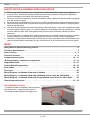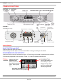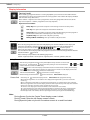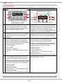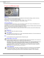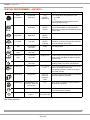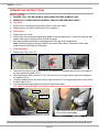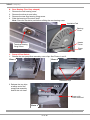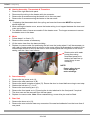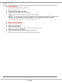
1
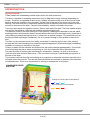
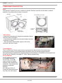
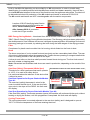
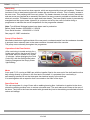
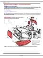
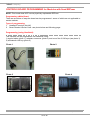
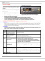
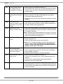
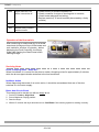
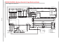
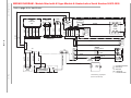
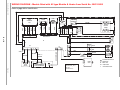
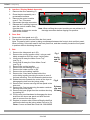
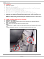
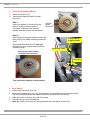
5407663 Issue 1
Nov. 2011
C00288739 - SM003340
Aqualtis
"B Energy"
CONDENSER
ELECTRONIC
TUMBLE DRYER
Pre 2011 Models:
8 Kg:
AQCF852BI
AQCF852BU
9 Kg:
AQCF952BI
AQCF952BS
AQCF952BU
2011 Models
Service
Information
9 Kg:
AQC9BF5SZ1
AQC9BF5TZ1
Indesit Company UK Ltd
© 2011 Reg. Office: Peterborough PE2 9JB Registered in London: 106725
Indesit Company
SAFETY NOTES & GENERAL SERVICING ADVICE
1. This manual is NOT intended as a comprehensive repair/maintenance guide to the appliance.
2. It should ONLY be used by suitably qualified persons having technical competence applicable
product knowledge and suitable tools and test equipment.
3. Servicing of electrical appliances must be undertaken with the appliance disconnected (unplugged)
from the electrical supply.
4. Servicing must be preceded by Earth Continuity, Earth Resistance & Insulation Resistance checks.
5. Personal safety precautions must be taken to protect against accidents caused by sharp edges on
metal and plastic parts.
6. After Servicing the appliance must be rechecked for Electrical Safety. In the case of appliances which
are connected to a water supply (i.e.: Washing Machines, Dishwashers & Food Centres etc.) checks
must be made for leaks from seals gaskets and pipe work and rectification carried out where
necessary.
7. It can be dangerous to attempt ‘DIY’ repairs / maintenance on complex equipment and the Company
recommends that any problem with the appliance is referred to its own Service Organisation.
8. Whilst the Company has endeavoured to ensure the accuracy of the data within this publication they
cannot hold themselves responsible for any inconvenience or loss occasioned by any error within.
INDEX
Safety Notes & General Servicing Advice . . . . . . . . . . . . . . . . . . . . . . . . . . . . . . . . . . . . . . . . .2
Technical Specifications . . . . . . . . . . . . . . . . . . . . . . . . . . . . . . . . . . . . . . . . . . . . . . . . . . . . . . .3
Dryer Function . . . . . . . . . . . . . . . . . . . . . . . . . . . . . . . . . . . . . . . . . . . . . . . . . . . . . . . . . . . . 4 - 5
Console Functions . . . . . . . . . . . . . . . . . . . . . . . . . . . . . . . . . . . . . . . . . . . . . . . . . . . . . . . . . 6 - 9
Component Description. . . . . . . . . . . . . . . . . . . . . . . . . . . . . . . . . . . . . . . . . . . . . . . . . . . 10 - 12
‘B’ Energy Rating - Additional Components . . . . . . . . . . . . . . . . . . . . . . . . . . . . . . . . . . 13 - 14
Programme Guide . . . . . . . . . . . . . . . . . . . . . . . . . . . . . . . . . . . . . . . . . . . . . . . . . . . . . . . 15 - 21
Control Board Programming . . . . . . . . . . . . . . . . . . . . . . . . . . . . . . . . . . . . . . . . . . . . . . . 22 - 25
Fault Codes . . . . . . . . . . . . . . . . . . . . . . . . . . . . . . . . . . . . . . . . . . . . . . . . . . . . . . . . . . . . . 26 - 28
Test Cycle . . . . . . . . . . . . . . . . . . . . . . . . . . . . . . . . . . . . . . . . . . . . . . . . . . . . . . . . . . . . . . . . . .29
Wiring Diagram - for Models fitted with A1 Module . . . . . . . . . . . . . . . . . . . . . . . . . . . . . . . .30
Wiring Diagram - for Models fitted with A2 Module before Serial No. 00612.0000 . . . . . . . .31
Wiring Diagram - for Models fitted with A2 type Module from Serial No. 00612.0000 . . . . .32
Dismantling Instructions . . . . . . . . . . . . . . . . . . . . . . . . . . . . . . . . . . . . . . . . . . . . . . . . . . 33 - 39
Serial Number Location
The serial number is located on the front panel
behind the door - open the door to see it.
The serial number should be 9 digits long.
Service Manual UK
English
2 of 42
Indesit Company
TECHNICAL SPECIFICATIONS
First Production
AQCF852... October 2008
AQCF952... October 2010
AQC9BF... October 2011
Features
Electronically controlled tumble dryer comprising of an interface module
fitted into the door and a control module mounted on the plinth,
connected by a serial link.
Country of Origin
Great Britain
Dimensions
Height: 850 mm
Width: 595 mm
Depth: 584 mm
Weight: 41 Kg (Packed)
Energy Class
B
Noise Level
68 dBA approximately
Drum Volume
112 litres
Drying Load
Dry weight maximum 8 Kg - AQCF852
Dry weight maximum 9 Kg - AQCF952 & AQC9BF5...
Programmes
16
Drying Sensing Levels
Up to 5 depending on programme selected.
Door Operation
Lever operated door catch
Heater
Before Serial No. 008160000 = 2050W @ 230V
After Serial No. 008160000 = 2300W @ 230V
Electronic Platform
EVO2 / Dryer
Heater Controls
Variable using electronic control and thermistors
Safety Thermostats
Cycling Thermostat:
One Shot Thermostat:
Rear Thermistor)
25°C = 400 KΩ to 540 KΩ
100°C = 15 KΩ to 17 KΩ
Front Thermistor
25°C = 400 KΩ to 540 KΩ
100°C = 15 KΩ to 17 KΩ
Motor
Before Serial No. 008160000 = Type 350
After Serial No. 008160000 = Type 362
Capacitor
8.5 uF
106°C
143°C (White Spot)
Production Changes
September 2009
November 2009
Nov / Dec.2009
May 2010
72mm Cooling Fan and new shape Inlet Ring introduced.
Stand-by feature introduced. This is incorporated in the User Interface module
A2 type Heater and Module introduced (not interchangeable with earlier type)
Motor covers removed, a new "BBC" module and a 2300W heater introduced.
Autumn 2011
Aesthetic changes to Base etc. Colour change from Grey to White.
Service Manual UK
English
3 of 42
Indesit Company
DRYER FUNCTION
Drying Overview
These models are freestanding tumble dryers with a full width metal door.
The drum is capable of accepting a maximum 8 Kg or 9Kg load of damp clothing (depending on
model). The drum is supported at the front by 2 wheels mounted on the front air duct and a single
bearing at the rear located in the rear panel. A shaft fixed to the rear of the drum runs in the rear
bearing. The drum is driven by a belt which passes around its periphery and onto the shaft of a motor
secured to the base of the dryer. The belt is tensioned by a pulley mounted to the motor.
The motor also drives two impellers (rotors), fixed to each end of its shaft. The front impeller draws
cold air into the machine, while the rear impeller recirculates drying air.
The addition of heat to the recirculating air is provided by a heating unit attached to the rear panel,
enabling the air to hold moisture when in contact with the wet load, thus causing it to dry. As the warm
recirculating air passes through the drum, it collects lint as well as moisture. To prevent the lint from
blocking the heat exchanger (condenser), the air is passed through a filter located in the front air
duct.
The filter unit is positioned so as to be easily removable for cleaning by the user. After passing
through the filter, the circulating air is ducted through passageways in a heat exchanger (condenser)
located in a housing on the base of the dryer.
Cold air is drawn into the machine and flows across the heat exchanger passageways. This cold air
is not mixed with the warm, damp recirculating air. See the condenser airflow picture below.
This has the effect of reducing the circulating air temperature, causing it to give up its moisture.
(Cold air holds less moisture than hot air.) The now warm cooling air is exhausted through slots in
the rear of the dryer.
The moisture removed from the recirculating air is pumped to a removable container mounted in the
left hand side of the console. The user can easily withdraw the container to dispose of the collected
condensed water. There is no requirement for venting to atmosphere on this dryer.
CONDENSER DRYER
AIR FLOW
Cooling Air Circuit (open to atmosphere)
Recirculating Air Circuit (sealed)
Service Manual UK
English
4 of 42
Indesit Company
Controls Overview
The user controls consist of an Digit display, programme selection buttons, option buttons;
Start/Pause button and an On/Off button.
The control system consists of a control module, 2 thermistors and a conductivity sensor.
The conductivity sensor is mounted in the front air duct. A single wire connects the sensor to the
control module. The thermistors and conductivity sensor sends values back to the control module.
The control module then determines the programme duration and dryness of the load to set values
for a particular programme held within the control module software.
The control module is located behind the right hand side panel and there is a service port behind the
plinth cover that allows attachment of a computer, Smart Card Reader or Handheld Device to
programme the Control Module.
The control module can be programmed with the relevant settings file if the module is replaced, the
eeprom file becomes corrupted or if an updated file becomes available.
Each of the sensing programmes has a maximum time of 240 minutes.
Once the Automatic cycle has started, the machine’s sensors, (front and rear thermistors and the
conductivity sensor) continually monitor the dampness of the drying clothes. Once a final dry time
has been determined, the display will update.
If the display counts down to 10 minutes and the clothes are not at the required dryness level, the
display will hold at 10 minutes, depending on the programme in progress and the material being
dried, the dryer will either wait until the correct dryness level is reached and move to the cool down
period, or wait until the machines sensors are able to recalculate the dryness time and the display
will update accordingly.
If, after the maximum programme time of 240 minutes, the clothes are still not dry, the programme
advances to cool tumble and completes the programme. No fault is indicated if this occurs.
The module also controls the heater. This has an upper and lower element. The lower (static)
element is permanently energised (except in cool tumble) and the upper element (dynamic) is cycled
on and off by the control module during a programme to maintain the correct temperature within the
drum for the programme selected.
If the user turns off the power or disconnects the mains cable or there is a power cut, the dryer will
remember its last settings and resume the programme when the start button is pressed.
The start of a programme can be delayed up to a maximum of 18 hours programmed in 1 hour steps.
Pre-crease care (see page 8) can only be selected if a timed delay has been selected; this option
tumbles the clothes for 3 seconds every 30 minutes for the duration of the time delay.
If selected, the Post crease care option (see page 8) tumbles the clothes after the programme has
finished for 3 seconds every 4 minutes up to a maximum duration of 10 hours.
In the event of a controls or thermistor failure, a one-shot cut-out thermostat is fitted as safety device.
Stand-by Mode - from November 2009, a new interface module with 'Stand-by' mode was
introduced.
30 minutes after a programme has finished, if the machine is still 'On' and no buttons have been
touched, the machine will go into Stand-By mode. The LEDs and display will switch off. To reactivate
and to remove the machine from Stand-By mode, briefly press the 'On/Off' button and the console
lights will illuminate. Another programme can then be started or the machine can be switched off by
pressing the 'On/Off' button.
Service Manual UK
English
5 of 42
Indesit Company
CONSOLE FUNCTIONS
AQCF852... & AQCF952...
AQC9BF...
On/Off Button & Light
Option Buttons and Lights
ECO
Light
Start/Pause
Button & Light
Programme
Progress Light
Display Panel
Sensor Dry
Programme Knob
Delay
Timer
Timed Dry
Clean Heat
Pump Filter
Empty
Water /
Clean Filter
Light
Child Lock
Button & Light
Option Buttons
ON OFF BUTTON and LIGHT
Push to switch the dryer On and Off.
If the button glows the dryer is turned on and either running or waiting to be started.
PROGRAMME KNOB AND INDICATOR
Used to select the required programme option. 16 timed auto and special programmes are available.
Consult the programme chart on pages 15 and 16, to see Programme descriptions.
Display
Countdown Timer
Gives Estimated time to
end of delay or cycle
Indicates Current
Dryness Level
Sensor cycles only
(See Sensing Levels)
Active. Auto Cycles
only
Displays during delay
start, auto, special and
manual programmes.
Indicates Time Set
Active. Manual Time Cycles Only
Service Manual UK
English
6 of 42
Indesit Company
Display Information
Sensing Levels
After selecting a programme that has a Sensing Dry Option, press and release the button until the
required dryness sensing level is displayed. If the sensing option is not available the display will flash
and the buzzer beeps three times.
Note: ‘Cottons - High Heat’ and ‘Jeans’ programmes are the only programmes which have all five
dryness level options - all other programmes have only 4 options.
Dryness levels available
Damp Dry: Dries your items ready to be ironed using a machine or rotary ironer.
Iron Dry: Dries you items ready to be ironed with a hand iron.
Hanger Dry: Dries you clothes ready to be hanged for final drying; Use this program if
you do not need the items to be fully dry as it uses less Energy.
Cupboard Dry: Dries your items ready to be put away.
Ready to Wear / Extra Dry : Dries your clothes ready to be worn.
Timed Dry
After selecting a Programme that has a Timed Dry Option, press the Timed Button and the display will
reduce the selected time each time you press and release this button (see Start and Programmes).
,
, , , , , , then
and then repeats.
Each press decreases the set time
If the Timer Dry option is not available the display will flash and the buzzer beeps three times.
The selected time remains displayed after the programme starts and cannot be changed after the after the
Start/Pause Button
is Pressed.
Note: Timed Dry is only available on the following programmes:
Cottons - High Heat, Cottons - Low Heat, Shirts - High Heat, Shirts - Low Heat, Synthetics, Delicates.
Delay Timer
After selecting a Programme that has a Delay Timer Option a delay start time can be selected.
advances the delay setting in 1 hour Increments from
to
then
Each press of the Delay button
and then after five seconds cancels the delay.
For delays of 10 hours or more the display counts down the time in hours for first ten hours, then the display
shows
and then counts down in minutes. For delays less then 9 hours or less the display shows hours
and minutes and then count down in minutes for all of the delay.
is pressed the time cannot be changed.
After the Start/Pause Button
symbol is off and the Time to End is displayed
When the delay period finished the
Time to End
If the delay icon
is off the time displayed is the Time to End of the programme running.
When timed programmes are selected the time displayed throughout the cycle is the actual time
remaining.
When an Automatic programme is selected the time displayed is an estimate of the time remaining.
When the programme is selected the display shows the time required to dry a full load, after around 10
minutes the controller calculates a better estimate of the cycle time
The time to end is displayed in hours and minutes and counts down each minute.
The colons between the hours and minutes display flashes to show that the time is counting down.
The Display also shows if there is a problem with your dryer, if this occurs the display will show F
followed by a fault code number, the four option lights and the pause light will also flash Orange.
Note:
During Sensor Cycles the Centre Timed display screen is blank;
During Timed Cycles the left Sensor screen is blank;
During Special cycles only the left Countdown screen is on and illuminated.
Service Manual UK
English
7 of 42
Indesit Company
OPTION BUTTONS
AQCF852... / AQCF952...
AQC9BF5...
Option Buttons & Lights
1.
3.
2.
4. 1.
3.
2.
4.
1 Mini Load
Should be selected if between 1 & 2 Kg of
clothes are to be dried. The Time to END
display is adjusted to give a more accurate
Cycle Time to end estimation time.
Extra Care
Not available on all cycles and dryness levels.
This option modifies drum movement during the
later stages of the cycle, creating a softer
movement of the clothes. (The drum pauses are
longer and the drum rotation is shorter.)
2 Alarm
Sound
If selected, the buzzer will sound at the end of If selected, the buzzer will sound at the end of the
the cycle. Beeps 3 times when the cycle
cycle. Beeps 3 times when the cycle finishes.
finishes.
3 Pre-Crease Care
Crease Care
Option can be selected if the Delay Start
Can be selected, if the clothes will not be
Option has been selected; the clothes are
removed as soon as the cycle is finished.
tumbled occasionally during the Delay period This option occasionally tumbles the clothes to
to help prevent creases developing.
prevent creases developing, while the clothes are
- 3 secs Clockwise
in the drum when the cycle is finished.
- 30 min Pause
- 3 secs clockwise
- 3 secs Anti -Clockwise
- 237 secs Pause
- 30 Pause--- continuously until programme
- 3 secs anticlockwise
starts.
- 237secs pause ……continuously until the
clothes are removed.
This option will run for a maximum of 10 hours.
High Heat
4 Post Crease Care
Not available on all cycles.
Can be selected, if the clothes will not be
removed as soon as the cycle is finished.
This option occasionally tumbles the clothes to
prevent creases developing, while the clothes
are in the drum when the cycle is finished.
- 3 secs clockwise
- 237 secs Pause
- 3 secs anti clockwise
- 237 secs pause ……continuously until the
clothes are removed.
This option will run for a maximum of 10 hours.
Service Manual UK
English
8 of 42
Indesit Company
Progress and Warning Lamps
ECO Led
The Eco LED will illuminate when the user adjusts the knob/option settings, which involve an
energy reduction, from the default settings.
Auto Cycles - If the sensing level is reduced. (Hanger, iron or damp dry)
Timed Cycles - If the time is adjusted to 120 minutes or lower.
Child Lock (Button)
To enable the Child Lock function, press and hold the "Child Lock" button until the Button Led
illuminates. All the controls on the dryer are now disabled.
If the selector is turned or an Option is pressed the Child Lock button will flash and the machine will
bleep, to remind the customer that the Child Lock is active.
To remove the controls child lock, press and hold the child lock button and until the button lamp
goes out.
Drying Led
Is illuminated when the machine is drying.
Cool Tumble
Is illuminated, when the dryer is on a cycle, and the heater element is off, this would be the
cool down period at the end of the cycle.
End
Is illuminated when the programme has finished its cycle.
Empty Water/ Clean Filter
Is illuminated (permanently "on"), at the end of every cycle as a reminder to the customer to
empty the water container and to clean the filter after every use.
If the Empty Water / Clean Filter Led illuminates during a cycle, (H2) would also be shown in
the display. The machine has sensed the water container is full, after approximately
1 minute the heater is turned off and continues for 10 minutes with cool air only, before
displaying the fault (H2) and LED. To continue the cycle, empty the container, push the
Start/Pause button and the machine will continue.
Clean Condenser
Is illuminated every 25 cycles to remind the customer the condenser should be regularly
removed and cleaned. The Clean Condenser Warning is only a reminder and is not
connected to any sensing device-It does not indicate the condition of the condenser.
Service Manual UK
English
9 of 42
Indesit Company
COMPONENT DESCRIPTION
Door
The Aqualtis Tumble Dryer door, holds the customer interface controls and the water container
handle is only visible when the door is opened.
Door Handle - Pull to Open
Condenser
location
Door Switch
A single unit comprising two single microswitches, fitted to
the front panel of the dryer.
- One microswitch signals to the module whether the door
is opened or closed.
- One microswitch disconnects supply to the motor
whenever the door is open.
Control Module
This is an Electronic Device that monitors and controls all devices within the tumble dryer.
A production module is pre programmed at the factory with the relevant programmed file.
Service Modules are supplied non programmed and it is necessary for the Module to be programmed
by the Service Engineer. See page 22 - 25 for Module programming.
A2 type Module
During week commencing
23/11/2009 (Serial No.
91123.0001), a new A2
power module and heater
assembly was introduced in
production. This change was
gradually introduced
between
23/11/09 and 02/01/10.
During this period production
may vary from the original
A2 Module in positon
Service Manual UK
English
10 of 42
Indesit Company
build to the A2 build depending on the availability of A2 components. In order to enable easy
identification for models produced with the A2 power module and heater assembly, there will be a
circular BLUE label attached to the rear of the machine near the appliance rating plate. The label will
be discontinued when full production of the A2 module and heater is achieved on 02/01/10.
The A2 module and heater are NOT interchangeable with the earlier components.
Location of BLUE identifying label fitted to
machines produced with A2 module and
heater, before January 2010.
After January 2010 all production
is with the A2 type module
BBC Energy Saving Module - Introduced from Serial Number 008160000 (August 16th 2010)
"BBC" (Best B Class) Energy Saving Module introduced. The B energy rating has been achieved by
the development of new firmware and a more intelligent dryness algorithm and settings file that enable energy savings to be made, by reducing the heat during the latter stages of the drying process.
Filter
Comprises of a plastic mesh moulded into its housing, which slides into the front air duct.
Drum
The drum comprises of a zinc coated front and rear body and two removable plastic lifters. The rear
of the drum is perforated to allow the passage of air. Fixed to the rear pressing is a support shaft which
runs in a bearing located in the rear panel of the dryer.
A drive pin and collar on the drum shaft prevents forward thrust during use. The front lock seam of
the drum rotates on bearing pads.
Note: Galvanised and Stainless steel drums are used in production, depending on the model of the
dryer.
One-Shot (Safety) Thermostat (White Spot)
Thermostat Location as seen inside heater cover
This device is a disc type thermostat set to operate
at 143°C. It is used as a safety device.
It is positioned above the element. If this device fails
it cannot be reset.
One Shot Operation for Dryers fitted with Module
Type A1:
The one-shot (safety) thermostat is wired in the
control module Neutral circuit. If the one-shot fails
open-circuit, the dryer will be DEAD. No fault code
will display.
Rear (NTC)
Thermistor
Cycling
Thermostat
One-shot
Thermostat
One Shot Operation for Dryers fitted with Module Type A2:
If the One-Shot (safety) Thermostat operates (opens) the machine will continue with the cycle, without
heating or drying the clothes, until the programme is completed. No fault code will display.
Cycling Thermostat
The cycling thermostat is mounted adjacent to the one-shot (safety) and is designed to open at
106°C. It limits the temperature of the heat entering the drum.
Service Manual UK
English
11 of 42
Indesit Company
Heater Unit
Consists of four coils wound on mica supports, which are supported by mica end insulators. These end
insulators fit into a steel pressing that also locates the rear thermal controls. This is fixed by screws to
the rear cover. This pressing also forms air guides. The heater elements, thermal controls, thermistors
and rear cover are supplied as an assembly and has a five-way connector provided to interface with the
electronic module. The heater has an upper and lower heater. The lower (static) heater is permanently
energised and the upper heater (dynamic) is cycled on and off by the control module during a
programme to maintain the correct temperature for the programme selected.
Note: Two different Wattage heaters have been used in production.
Before Serial Number: 008160000 = 2.05 KW
From Serial Number: 008160000 = 2.3 KW
See page 13 - BBC introduction.
Pump & Float Switch
Mounted on the bottom right hand side of the rear panel, condensate water from the condenser chamber
is pumped via an external hose to the water container situated behind the console.
The pump runs continually throughout the programme.
Operation of the Float Switch:
After continuing to tumble and dry for a
further one minute, the dryer will turn off
the heater and cool tumble for a further
10 minutes - before displaying the Fault
Code H20, with the Start/Pause button
flashing Orange and the Empty Water
light flashing.
Motor
A two pole P.S.C running at 2800 rpm with the impeller fitted to the rear end of the shaft and the drive
belt running directly in grooves in the front end of the shaft. It is protected from overload by a
self-resetting internal cut-out that interrupts the electrical supply to the windings.
It is used together with a capacitor that is mounted on the base of the dryer.
Drum Rear Seal
This unit comprises of a ring of foam with a webbing bearing face. Lubrication is applied to the drum
where the webbing surface runs, to reduce noise and wear. The seal reduces air losses at the rear of
the drum. The joints in the foam are sealed with glue and the joints in the webbing are stitched to further
reduce air leakage.
Service Manual UK
English
12 of 42
Indesit Company
‘B’ Energy Rating - Additional Components Information
BBC (Best B Class) Introduction
From Serial Number 008160000 (16th June 2010), a new module, heater, motor and condenser have
been introduced, and the base and motor covers, have been removed (see below).
The new energy saving module in combination with a more powerful heater maintain the "B" rated
Energy Efficiency.
Energy Saving Module Function
BBC (Best B Class) Energy Saving Module introduced. The B energy rating has been achieved by the
development of new firmware and a more intelligent dryness algorithm and settings file which enable
energy savings to be made.
BASE Assembly
Aqualtis ‘B’ Energy Condenser Dryers have additional
components to improve airflow efficiency.
A) Base Cover *
B) Motor Top Cover *
C) Motor Cover Inner *
D) Motor Cover Outer *
E) Base Duct Lower
B
D
C
E
A
These covers are used
to retain the heat within
the Drying System to
increase the
Condenser efficiency.
* Note: These covers A, B, C & D are fitted in production up to Serial Number 008160000.
Service Manual UK
English
13 of 42
Indesit Company
HEATER COVER ASSEMBLY
A hole in the bottom of the Heater Cover diverts condensate onto the wick (sponge).
Any condensate will be absorbed into the wick and evaporated away by the heat of the cover.
Wick (sponge)
Back Panel
Inside view of
rear cover:
Drain
Hole
Absorbent
Wick
Service Manual UK
English
14 of 42
Indesit Company
PROGRAMME GUIDE - AQCF852... / AQCF952...
Programmes Table
! If the On/Off light is not lit; Press the On/Off Button
Post Dry Programmes
Programme What it does
and then select programme.
How to set it
Notes / Options available
Easy Iron
Brief programme
(approximately 10 minutes) 1.
that softens fibres of clothing 2.
3.
that is ready for ironing.
Position the PROGRAMME knob on
Select Alarm Option if required
Press the Start Button.
AIRING
20-minute programme that
airs: your clothes with cool
air. Use also to cool warm
clothes.
Position the PROGRAMME knob on
Select Alarm Option if required
Press the Start Button
Cottons
Programme What it does
Dries: your Cotton
Cottons - High clothes on High heat
Heat
Cottons - Low Dries: your Cotton
Heat
clothes on Low heat
Shirts
Programme What it does
Shirts - High
Heat
Shirts - Low
Heat
Dries: your Cotton
Shirts on High heat
Dries: your Synthetic
Shirts on Low heat
Programme What it does
Jeans
Dries: your Cotton
clothes on High heat
1.
2.
3.
.
! This is not a drying programme
(see previous page)
Options available
Alarm
.
Alarm
How to set it
Notes / Options available
1.
Position the PROGRAMME knob on.
Alarm
2.
Choose Timed
Pre care
Mini Load
3.
4.
see next page - Or
If Timed Drying
To change from default dryness setting
button
press and release Dryness Levels
until required level is displayed.
Select any Options if required.
Press the Start Button.
1.
Position the PROGRAMME knob on.
See Timed
2.
Select a drying time, see Timed
or Automatic.
option
, Delay Timer
,
, Post care
Dryness options, Automatic
Damp Dry,
Iron Dry,
Hanger Dry,
Cupboard Dry,
Extra Dry
next page
next page
How to set it
Notes / Options available
1.
Position the PROGRAMME knob on.
Alarm
2.
Choose Timed
Mini Load
3.
4.
see next page - Or
If Timed Drying
To change from default dryness setting
button
press and release Dryness Levels
until required level is displayed.
Select any Options if required.
Press the Start Button.
1.
Position the PROGRAMME knob on.
Alarm
2.
Choose Timed
or Automatic.
or Automatic.
option
option
Pre care
, Delay Timer
,
, Post care
Dryness options, Automatic
Iron Dry,
Hanger Dry,
Cupboard Dry.
Pre care
, Delay Timer
,
, Post care
see next page - Or
If Timed Drying
To change from default dryness setting
press and release Dryness Levels
button
until required level is displayed.
3. Select any Options if required.
4. Press the Start Button.
Mini Load
How to set it
Notes / Options available
1.
2.
3.
Position the PROGRAMME knob on.
Select any Options if required.
Press the Start Button.
Service Manual UK
Dryness options, Automatic
Iron Dry,
Hanger Dry,
Cupboard Dry.
Alarm
Pre care
, Delay Timer
, Post care
An Automatic Programme
English
15 of 42
,
Indesit Company
PROGRAMME GUIDE - AQCF852... / AQCF952... continued
Programmes Table
Programme What it does
Synthetics
Dries: your synthetics
clothes on High heat
How to set it
Notes / Options available
1.
Position the PROGRAMME knob on.
2.
Choose Timed
or Automatic.
If Timed Drying
see below - Or
To change from default dryness setting
press and release Dryness Levels
until required level is displayed..
3. Select any Options if required.
4. Press the Start Button.
Bed & Bath
Duvet
Cotton
Duvet
Synthetic
Wool
Silk
Baby Cycle
Lingerie
Delicates
Dries your Towels and
bedding on High Heat 1.
2.
3.
Dries your Duvet on
High Heat
1.
2.
3.
Dries your Duvet
bedding on Low Heat 1.
2.
3.
Dries: your Woollen
1.
clothes,
2.
(see previous page)
3.
Dries your Silk items
on Low Heat
1.
2.
3.
Dries your Baby
clothes on Low Heat 1.
2.
3.
Dries your Lingerie on
Low Heat
1.
2.
3.
Dries: your clothes on
1.
Low heat setting,
ready to be worn.
2.
(e.g. Acrylics)
3.
4.
Alarm
option
button
Automatic
Damp Dry,
Alarm
Pre care
x
Alarm
Iron Dry,
Cupboard Dry.
, Delay Timer
,
, Post care
An Automatic Programme
, Delay Timer
,
, Post care
Pre care
An Automatic Programme
Alarm
Position the PROGRAMME knob on
Select any Options if required.
Press the Start Button.
Position the PROGRAMME knob on
Select any Options if required.
Press the Start Button.
, Post care
Pre care
Hanger Dry,
Position the PROGRAMME knob on
Select any Options if required.
Press the Start Button.
Position the PROGRAMME knob on
Select any Options if required.
Press the Start Button.
,
Mini Load
Dryness options,
Position the PROGRAMME knob on
Select any Options if required.
Press the Start Button.
Position the PROGRAMME knob on
Select Alarm Option if required.
Press the Start Button.
, Delay Timer
, Delay Timer
,
, Post care
Pre care
An Automatic Programme
.
Alarm
x An Automatic Programme
Alarm
, Delay Timer
,
, Post care
Pre care
An Automatic Programme
Alarm
, Delay Timer
,
, Post care
Pre care
An Automatic Programme
Alarm
, Delay Timer
Position the PROGRAMME knob on
Select any Options if required.
Press the Start Button.
, Post care
Pre care
An Automatic Programme
Position the PROGRAMME knob on
Alarm
,
, Delay Timer
,
, Post care
Programme required (see Timed below) Pre care
If Timed
Otherwise default is Automatic
x The default is Automatic
Select any Options if required
Press the Start Button
Timed
First select a programme (see programmes table)
Programme What it does
How to set it
Always use timed drying for 1. Press and release the Timed Button until the display
Timed Drying loads less than 1kg or if you
shows the required selection. Each press decreases
(180, 160, 120, prefer a different dryness
,
,
, , , ,
then
and
time
90, 60, 30 or 20 result.
then repeats.
minutes)
The heat setting depends on x Delicates have maximum time of
the Programme (material
x After
is displayed, Automatic
option is
option) selected;
available if you change your mind.
2. Select any Options if required
3. Press the Start Button.
Service Manual UK
Notes / Options available
Options available
Alarm
, Delay Timer
,
Pre care
, Post care
Consult suggested drying times (see
Laundry)
The last 10 minutes of these
programmes is the cool tumble
phase.
English
16 of 42
Indesit Company
SPECIAL PROGRAMMES - AQCF852... / AQCF952...
Symbol
Programme
Wool
Programme
Approx.Time/Heat
60 minutes
High Heat
Max. Weight
1 kg
(approx
3 sweaters
Notes
For Tumble dryer safe garments, with
symbol.
It is recommended garments re turned inside
out before drying.
Jeans
85 minutes
High Heat
3 kg
(approx.
4 pairs)
For garments made of Denim Cotton, turn
front pockets inside out. Garments with
embroidery or elasticated waistbands should
not be dried.
Shirts
High Heat
80 minutes
High Heat
3 kg
(approx.
10 shirts)
For Shirts made from cotton
Shirts
Low Heat
65 minutes
Low Heat
3 kg
(approx.
14 shirts)
For Shirts made from synthetic materials, or
a mixture of natural and synthetic materials
such as Polyester and cotton
Silk
110 minutes
Low Heat
0.5kg
Duvet Cotton
120 minutes
Low Heat
Single Duvet
Duvet
Synthetic
115 minutes
Low Heat
Single Duvet
Baby Cycle
120 minutes
Low Heat
2 kg
For baby’s small items of clothing and
bedding made from Cotton and Chenille.
Lingerie
90 minutes
Low Heat
1 kg
For very delicate lingerie including silk.
Buttons and hooks should be fastened
before drying.
Note: Low Heat. Heater Cycles to maintain
delicate temperature during cycle.
For Delicate Silk.
Loads using this programme will usually be
ready to use, the edges or seams may be
slightly damp.
Notes
• Times shown above are for the driest setting available for the programme concerned.
• All 5 Sensing Levels are not available on all Programmes.
• The Cool down period varies between 15 and 4 minutes depending on the cycle selected.
• Times are estimated for an average load. The actual duration will vary, depending on the
size and type of the load being dried.
• The display may show 10 minutes for an extended period if the clothes are not dry when the
cool down period is reached.
• The display may update its time to end during the cycle., if its sensors calculate either more
or less time is required to dry the clothes to the required dryness level.
• Loads using these programmes will usually be ready to use or wear, in some situations the
edges or seams may be slightly damp.
Service Manual UK
English
17 of 42
Indesit Company
PROGRAMME GUIDE - AQC9BF5...
Programmes Table
! If the On/Off light is not lit; Press the On/Off Button
Programme
Easy Iron
Refresh
Cottons
and then select programme.
What it does
How to set it
Brief programme (approximately 10 minutes) that softens
fibres of clothing that is ready
for ironing.
1. Position the PROGRAMME knob on
2. Select Alarm Option if required.
3. Press the Start Button .
.
! This is not a drying programme (see previous page).
Options available
Sound .
20 min cool programme to air
your clothes
1. Position the PROGRAMME knob on
2. Select Alarm Option if required.
3. Press the Start Button .
.
Sound
Dries: your Cotton clothes.
1. Position the PROGRAMME knob on
2. Choose Sensor Dry
or Timed Dry
(see next page).
3. Select any Options if required.
4. Press the Start Button .
.
. High Heat .
Sound . Delay Start . Crease care
Extra Care
.
Sensor Dry option, automatic drying:
Damp dry
, Iron dry
, Hanger dry
Cupboard dry
, Ready to Wear
.
1. Position the PROGRAMME knob on
2. Choose Sensor Dry
or Timed Dry
(see next page).
3. Select any Options if required.
4. Press the Start Button .
.
Sound
N.B: Max. load 6 kg (with
Low Heat option)
Dries your shirt.
Shirts
Notes / Options available
Dries denim clothes on a high
heat.
1. Position the PROGRAMME knob on .
2. Choose Sensor Dry
(see next page).
3. Select any Options if required.
4. Press the Start Button .
Dries: your synthetics clothes.
1. Position the PROGRAMME knob on
2. Choose Sensor Dry
or Timed Dry
(see next page).
3. Select any Options if required.
4. Press the Start Button .
Jeans
Synthetics
.
. High Heat
.
Sensor Dry option, automatic drying:
Damp dry , Iron dry , Hanger dry
Cupboard dry
.
. Delay Start
. Crease care
Sound . Delay Start . Crease care .
Sensor Dry option, automatic drying:
, Iron dry
, Hanger dry
Damp dry
Cupboard dry
, Ready to Wear
.
(We suggest to use only Ready to Wear).
Sound
.
. Delay Start
. Crease care
.
Sensor Dry option, automatic drying:
, Iron dry
, Hanger dry
,
Damp dry
.
Cupboard dry
Dries your Towels and
bedding.
1. Position the PROGRAMME knob on
.
2. Choose Sensor Dry
(see next page).
3. Select any Options if required.
4. Press the Start Button .
Sound . Delay Start . Crease care
. Extra Care
Sensor Dry option, automatic drying:
Damp dry
, Iron dry
, Hanger dry
, Cupboard
. (We suggest to use only Cupboard dry).
dry
Dries your Duvet.
.
1. Position the PROGRAMME knob on
2. Choose Sensor Dry
(see next page).
3. Select any Options if required.
4. Press the Start Button .
. High Heat .
Sound . Delay Start . Crease care
Sensor Dry option, automatic drying:
Damp dry
, Iron dry
, Hanger dry
,
. (We suggest to use only Cupboard dry).
Cupboard dry
Dries: your Woollen clothes.
1. Position the PROGRAMME knob on
2. Select any Options if required.
3. Press the Start Button .
.
Sound
.
Dries your silk items.
1. Position the PROGRAMME knob on .
(see next page).
2. Choose Sensor Dry
3. Select any Options if required.
4. Press the Start Button .
Sound
.
Sensor Dry option, automatic drying:
, Iron dry
, Hanger dry
,
Damp dry
(We suggest to use only Cupboard dry).
Cupboard dry
Dries your baby clothes.
1. Position the PROGRAMME knob on .
(see next page).
2. Choose Sensor Dry
3. Select any Options if required.
4. Press the Start Button .
Sound . Delay Start . Crease care .
Sensor Dry option, automatic drying:
Damp dry
, Iron dry
, Hanger dry
,
Cupboard dry . (We suggest to use only Cupboard dry).
Anti Allergy treatment for your
cotton clothes.
1. Position the PROGRAMME knob on
2. Select any Options if required.
3. Press the Start Button .
.
Sound
. Delay Start
. Crease care
.
Dries your cotton or synthetic
clothes in less time.
1. Position the PROGRAMME knob on
2. Select any Options if required.
3. Press the Start Button .
.
Sound
. Delay Start
. Crease care
.
Bed & Bath
Duvet
Wool
Silk
Baby
Delicate
Anti Allergy
Quick Dry
Service Manual UK
English
18 of 42
.
Indesit Company
PROGRAMME GUIDE - AQC9BF5... - continued
Programme
What it does
How to set it
Dries your sports clothes.
1. Position the PROGRAMME knob on
2. Select any Options if required.
3. Press the Start Button .
Dries your cuddly toy.
1. Position the PROGRAMME knob on
2. Select any Options if required.
3. Press the Start Button .
Heats your XS[IPFEXLVSFI
1. Position the PROGRAMME knob on
2. Select any Options if required.
3. Press the Start Button .
Activewear
Cuddly Toys
Heat & Enjoy
Notes / Options available
.
.
.
Sound
. Delay Start
. Crease care
Sound
. Delay Start
.
.
-
Sensor Drying and Timed Drying
First select a programme (see programmes table).
Programme What it does
Sensor
Drying
Timed
Drying
(220, 180,
150, 120,
90, 60 or 40
minutes)
How to set it
Notes / Options available
Always use Sensor Dry if possible for drying your clothes. It
will guarantee you best drying
results.
The heat setting depends
on the programme (material
option) selected.
1. Press and release the sensor Dry button until
the display shows the desired selection. Each
press advances , , , ,
and then
repeats.
! Some sensing programmes do not have all five
dryness level options.
2. Select any Options if required.
3. Press the Start Button .
Options available
Sound . Delay Start . Crease care .
High Heat . Extra Care
.
Consult suggested drying times (see Laundry).
The last 3 minutes of these programmes is the cool
tumble phase
.
Always use timed drying
option if you want to decide
the drying time.
The heat setting depends
on the Programme (material
option) selected.
1. Press and release the Timed Button until the
display shows the required selection. Each
decreases time 220’, 180’, 150’, 120’, 90’,
60’, 40’ and then repeats.
w&EF](IPMGEXIWLEZIEQE\MQYQXMQISJ150’.
2. Select any Options if required.
3. Press the Start Button .
Options available
Sound . Delay Start .Crease care . High Heat
Consult suggested drying times (see Laundry).
The last 3 minutes of these programmes is the cool
tumble phase
.
! For the best performance do not open the door before the cycle has finished.
Service Manual UK
English
19 of 42
.
Indesit Company
SPECIAL PROGRAMMES - AQC9BF5...
Symbol
Programme
Approx.Time/Heat
Wool
Programme
60 minutes
High Heat
Max. Weight
1 kg
(approx.
3 sweaters)
Notes
For Tumble dryer safe garments, with
symbol.
It is recommended garments be turned
inside out before drying.
Jeans
85 minutes
High Heat
3 kg
(approx.
4 pairs)
For garments made of Denim Cotton, turn
front pockets inside out. Garments with
embroidery or elasticated waistbands should
not be dried.
Shirts
High Heat
80 minutes
High Heat
3 kg
(approx.
10 shirts)
For Shirts made from cotton
Shirts
Low Heat
65 minutes
Low Heat
3 kg
(approx.
14 shirts)
For Shirts made from synthetic materials, or
a mixture of natural and synthetic materials
such as Polyester and cotton
Silk
110 minutes
Low Heat
0.5kg
Duvet High
Heat
120 minutes
Low Heat
Single Duvet
Duvet Low
Heat
115 minutes
Low Heat
Single Duvet
Baby Delicate
120 minutes
Low Heat
2 kg
Cuddly Toys
200 minutes
2 or 3 cuddly
toys
Dries at low temperatures with reduced drum
action. Clockwise rotation only.
For Allergy protection, freeze for 24 hours
then wash and dry.
Active Wear
120 minutes
2 kg (e.g.
Gore-Tex,
polyester,
nylon)
Drying the garment after washing reactivates
the water repellent treatment.
Heat & Enjoy
Until stopped by the
customer. Time out
240 minutes
3 kg
Dries at 37°C. Useful for drying clothes in
winter before dressing.
Quick Dry
30 minutes
1 kg
Energy saving for small loads.
Front Thermistor monitored.
Anti Allergy
See Anti Allergy
page 17
Wet Load 9 kg
Dry Load 4 kg
For Delicate Silk.
Loads using this programme will usually be
ready to use, the edges or seams may be
slightly damp.
For baby’s small items of clothing and
bedding made from Cotton and Chenille.
See Anti Allergy page 21
See Notes overleaf.....
Service Manual UK
English
20 of 42
Indesit Company
Notes
• Times shown are for the driest setting available for the programme concerned.
• All 5 Sensing Levels are not available on all Programmes.
• The Cool down period varies between 15 and 4 minutes depending on the cycle selected.
• Times are estimated for an average load. The actual duration will vary, depending on the
size and type of the load being dried.
• The display may show 10 minutes for an extended period if the clothes are not dry when the
cool down period is reached.
• The display may update its time to end during the cycle., if its sensors calculate either more
or less time is required to dry the clothes to the required dryness level.
• Loads using these programmes will usually be ready to use or wear, in some situations the
edges or seams may be slightly damp.
Anti-Allergy Programme
The Anti Allergy cycle has a unique programme profile:
Normal operation
Drum forward and reverse
About 20 minutes
Cycle Duration
80 minutes - reverse only Normal operation
with short pauses.
Drum forward and reverse
80 minutes
Depends on load
The Anti-Allergy phase tumbles and heats for 80 minutes in an anti-clockwise direction, with a short
pause every 5 minutes. This is to keep the temperature constant (approximately 70°C).
Note:
The Anti-Allergy phase of the drying cycle is not intended to dry clothes. The drying phase continues
once the Anti-allergy phase has completed.
Service Manual UK
English
21 of 42
Indesit Company
CONTROL BOARD PROGRAMMING for Modules with fixed EEProm
NOTE: This board does NOT have a physically replaceable EEProm.
Programming a Main Board
There are a number of ways the board can be programmed - some of which are not applicable to
certain markets.
Types of programming:
1. Handheld Terminal (Not UK)
2. Emit / Memwriter (UK Indesit Service Engineers)
3. Smart Reader & Smart Card (certain areas of UK market) see photo below and following page.
Smart Card Reader
Smart Card
this card hold the program file
and can only be used ONCE.
PROGRAMMING (Using EMIT)
This machine can be programmed via the Emit, using a USB lead (Part number C00222800),
Hardware key (Part number C00115587) and the Memwriter software.
Black Hardware Key
USB - Serial Cable - examples
A Hardware Key Pin is available
(order Part No. C00114723, qty. 1)
Service Manual UK
English
22 of 42
Indesit Company
PROGRAMMING (Using Smartcard Reader / Card)
If the Main Module has been replaced during a repair the board will require programming using the
following method.
1. Do NOT connect the dryer to electrical supply at
this point.
Smart Card Reader
and Smart Card in use
2. Insert the pre-programmed card into the Card
reader. Care must be taken at this point to ensure
the card is inserted correctly with the Chip on the
card facing the PCB of the Reader.
3.
Insert the Reader & Card into module connection
port located at the front of the dryer - see photo.
4.
Connect the dryer to the Electrical supply;
The LED's on the Smart Card Reader will light in the
following sequence:
a)
b)
c)
Red OFF: Good Communication between Smart
Card Reader & Card.
Red OFF; Green Blinking: Download taking place.
At end of download from Smart Card to Module,
Green ON ---> Download OK.
or
d) At end of download from Smart Card to Module,
Red ON ---> Download NOT OK.
5.
Programming Complete, disconnect the machine
from Electrical supply.
6.
Remove the Smart Card Reader.
Service Manual UK
Module
Connection
Port
SmartCard
Reader
SmartCard
English
23 of 42
Indesit Company
Service Manual UK
Programming using Smart Card Reader - Flowchart:
24 of 42
English
Indesit Company
CONTROLS BOARD PROGRAMMING for Modules with fixed EEProm
NOTE: This board does NOT have a physically replaceable EEProm.
Programming a Main Board
There are a number of ways the board can be programmed - some of which are not applicable to
certain markets.
Types of programming:
1. Handheld Terminal (Not UK)
2. Smart Reader & Smart Card - see photo below and following page.
Programming (using Handheld):
This machine can be programmed via Handheld, using:
1) a serial cable (photo 1), adapters connector (photo 2) and one of the 2 HW keys (see photo 3)
2) a Bluetooth HW key (photo 4)
Photo 1
Photo 2
Photo 3
Photo 4
Service Manual UK
English
25 of 42
Indesit Company
FAULT CODES
Example of a Fault Code
In the event of a fault being detected by the
electronics, a code will appear in the LCD
display.
These codes are listed in the following table.
Please Note:
•
Components with a low resistance to
Earth may cause erroneous faults or
loss of the display.
•
Always check relevant wiring and
connector blocks security before considering replacing the modules.
•
On ALL automatic programmes; there is no heat during the first 3 minutes.
The first 10 minutes of all automatic cycles is used to calculate the drying time.
All 4 options button lights and the Start/Pause
light will flash when a Fault Code is displayed.
ONE-SHOT STAT OPERATION - Applicable to Fault Codes.
- A1 Module
The one-shot thermostat is wired into the Neutral supply of the module. If the One-Shot
Thermostat operates and opens the machine will be 'dead' and the display will be blank.
A fault code will NOT be displayed.
- A2 Module
If the one-shot thermostat operates and opens, the machine will continue with the cycle
with no heat. A fault code will NOT be displayed.
FAULT
Cause
Control Action
F01
The motor is running
when it should be off.
• Check if module connector J3 has shorted due to moisture.
• Replace module.
F02
Open circuit between
module and motor
Common.
• Check security of module connector J3;
• Test motor Common (TOC);
• Check wiring between J3 and motor.
F03
Front thermistor open or
short circuit.
• Check security of module connector J12;
• Test from connector pins (approximately 500 Kohms);
• If open or short circuit, test thermistor and wiring between
thermistor and J12 to locate fault.
F04
Pump working when
should be off.
• Check security of module connector J5;
• Check connector for signs of shorting due to moisture;
• Replace module (F04 would normally be caused by a faulty
module).
F05
Pump is not working
when it should be on.
• Check security of module connector J5;
• Check connector for signs of shorting due to moisture;
• Replace module (F05 would normally be caused by a faulty
module).
F06
Not used.
----
Service Manual UK
English
26 of 42
Indesit Company
F07
Lower element failure
(or Heater Plug not
connected to module.)
• Check security of module connector J4;
• Test between pins 4 and 3 on J4 (approximately 48 Ohms);
• If open circuit, test lower element and wiring between J4
and the heater.
F08
Lower element is energised when it should be
off.
• Check security of module connector J4;
• Check connector for signs of shorting due to moisture;
• Test heater elements and wiring;
• Replace module (F08 would normally be caused by a faulty
module).
F09
Error Set Up File.
Eeprom is either not programmed or is not functioning.
• If the module is a production board, replace the module;
• If the module has an Eeprom socket, check the eeprom is
correctly inserted and programmed.
F10
Open circuit in the
heater Common wiring.
• Check the wiring between the cycling stat and the module;
• Check wiring between module connector J4 and the heater;
• Test heater elements.
Note:- Frequent cycling stat operation can cause F10, check
filter and condenser for blockages. The module checks and
waits 3 times before displaying F10.
F11
Open circuit pump
circuit.
• Test continuity of pump;
• Check connector J5;
• Check wiring between pump and module J5.
Note:- F11 is usually caused by a fault in the pump circuit
not the module. Auto cycle being used fault displays
within 1 minute Time and Wool cycles being used fault
displays at the end of the cycle.
F12
No communication
between display module
and control module.
• Check connector J9 on module;
• Check wiring between module connector J9 and display;
• Check display connector;
• Replace module, display or wiring as required.
F13
Rear thermistor open or
short circuit.
• Check security of module connector J4;
• Test from J4 connector pins 1 and 2 (approximately 500
Kohms);
• If open circuit, test thermistor and wiring between
thermistor and J4 to locate fault.
F14
Upper element failure
• Check security of module connector J4;
• Test between pins 4 and 5 on J4 (approximately 48 ohms);
• If open circuit, test upper element and the wiring between
J4 and the heater.
Service Manual UK
English
27 of 42
Indesit Company
F15
Upper element is on
when it should be off.
F16
Not used.
F17
Master Relay contacts
welded closed.
• Check security of module connector J4;
• Check connector for signs of shorting due to moisture;
• Check heater elements and wiring;
• Replace module (F15 would normally be caused by a faulty
module).
• Replace module.
Operation of the float switch:
After continuing to tumble and dry for a further
one minute, the dryer will turn off the heater and
cool tumble for a further 10 minutes - before
displaying the Fault Code H20, the Empty
Water light flashing the Start/Pause button
flashing Orange.
Servicing Notes
Drum Thumping Noise - AQCF852...
When first started, it is normal for the drum to make a thumping noise for approximately 2 minutes,
while the drum support wheels centralise to the load conditions.
No Motor Action
When diagnosing the cause of no motor action, it should be remembered that one of the door
switches is in the motor supply.
Basic Auto Circuit Check
This check must be carried out with an empty drum.
1. Set AUTO Cotton - High Heat
2. Set on Maximum Drying position.
3. Start the Dryer.
4. Within 15 minutes the dryer should move to Cool Down if the sensing system is working correctly.
Service Manual UK
English
28 of 42
Indesit Company
Auto Test
Required
> Hardware Key with a Test Switch (see photo.)
> Test Lead approximately 1.5 metres long with a 270 KW resistor in
series with a conductive magnet at one end, and a ring connector at the
other.
>
Hardware Key
with Test switch
Amp meter.
With the machine disconnected from the Electricity supply.
1. Attach the magnet end of the test lead on to the conductivity sensor.
2. Attach the other end of the test lead to an earth point. One of the rear
panel fixing screws is recommended.
3. Connect the Hardware key to the module. (access behind the plinth)
3a Select Cotton High Heat programme on selector.
4. START TEST
4a Plug the machine into the electricity supply, but do not switch on.
4b Switch the Test button on the Hardware key, To Test Position
The Display Shows Start Led green, Extra Dry bar, and 2:50
Drum Rotates anti clockwise. No Heat (approx. 1 amp)
4c Press the Post Crease care Button
The Display shows Start Led, Extra Dry bar, 2:50 and Post Care Led.
The Drum Stops
The Drum restarts rotating clockwise. Half heat. (approx. 5 or 6 amps)
4d Press the Alarm Button
The Display shows Start Led, Extra Dry bar, 2:50 Post Care and Alarm Led’s.
Drum continues to revolve clockwise. Full Heat. (approx 10 to 11amps)
5. Conductivity Sensor Test
Press the Post Crease Care button again
The Heater Switches Off
The Drum Stops.
The Display shows Extra Dry bar, 2:50 and Alarm Led.
> If the Conductivity Sensor is working correctly.
The Drum Starts to rotate anti clockwise.
The Display shows Start Led green, Extra Dry Bar, 2:50. in the display.
> If the Conductivity Sensor is Faulty.
The Display briefly flashes END and Start Led flashes green, plus Drying, Cool Tumble and Empty
Water/Clean filter Led’s come on.
The drum does not rotate.
Note: If a fault is detected the fault code will display in the display on the console and in the Test Plug
screen.
Service Manual UK
English
29 of 42
Indesit Company
Refer to page 10 for identification
ORANGE
3
2
BLACK
BROWN
BROWN
4
RED
WHITE
ORANGE
5
MAIN MODULE
1
J4
GREY
BLUE
GREY
2
1
1
J11
4.8
2
BLUE
GREEN/YELLOW
J3
BROWN
WHITE
WHITE
DOOR
SWITCH (1)
3
M
MAINS CONNECTION
WITH SUPPRESSION
English
L
N
E
1
BLACK
2
RED
3
CAPAC
-ITOR BLACK
PB
PB RED
DOOR SWITCH (2)
WHITE
M
WHITE
BLACK
SENSING
STRIP
J10
4
FRONT NTC
J9
HEATER & COVER ASSEMBLY
CYCLING
THERMOSTAT
UPPER
HEATER
LOWER
RED
RED
RED
BLUE
ONE SHOT
CUT OUT
1
2
BLUE
BLUE
BLUE
BLUE
30 of 42
BLUE
PUMP
NTC
FLOAT
SWITCH
USER
INTERFACE
PCB
WHITE
wd-160024345.ai
RED
Service Manual UK
WIRING DIAGRAM - Machines fitted with A1 type Module and Heater
DRUM
ASSY
MOTOR WITH
PROTECTOR
= LOCKING RECEPTACLE
= INSULATOR
M = MALE TAB
PB = PIGGY BACK
F = FLAG RECEPTACLE
Indesit Company
Refer to page 10 for identification
RED
5
4
MAIN MODULE
31 of 42
J9
3
2
BLUE
UPPER
HEATER
LOWER
1
J4
GREY
J1
GREY
4
3
2
1
1
J11
4.8
BLACK
2
GREEN/YELLOW
BLUE
BROWN
WHITE
WHITE
J3
DOOR
SWITCH
MAINS CONNECTION
WITH SUPPRESSION
L
N
CAPAC
-ITOR BLACK
PB
1
2
PB RED
RED
3
WHITE
WHITE
BLACK
DOOR
SWITCH (2)
SENSING
STRIP
J10
BLUE
ORANGE
BROWN
ORANGE
WHITE
GREY
BROWN
RED
NTC
RED
Yellow
BLUE
BLUE
BLUE
BLUE
BLUE
1
2
HEATER & COVER ASSEMBLY
CYCLING
THERMOSTAT
ONE SHOT
CUT OUT
BLACK
PUMP
FRONT NTC
FLOAT
SWITCH
USER
INTERFACE
PCB
Yellow
Service Manual UK
WIRING DIAGRAM - Models fitted with A2 type Module & Heater before Serial Number 00612.0000
M
DRUM
ASSY
E
English
5407479wd_earlyA2.pdf
(from 16002511500)
MOTOR WITH
PROTECTOR
= LOCKING RECEPTACLE
= INSULATOR
M = MALE TAB
PB = PIGGY BACK
F = FLAG RECEPTACLE
Indesit Company
Refer to page 10 for identification
BLACK
32 of 42
RED
5
4
MAIN MODULE
J9
3
2
BLUE
UPPER
HEATER
LOWER
1
J4
GREY
A2
J1
GREY
4
3
2
1
1
J11
4.8
BLACK
2
GREEN/YELLOW
J3
WHITE
BROWN
BLUE OR
BROWN
WHITE
DOOR
SWITCH
MAINS CONNECTION
WITH SUPPRESSION
English
L
N
E
CAPAC
-ITOR BLACK
PB
1
2
PB RED
RED
3
WHITE
WHITE
BLACK
5407479wd_A2.ai
A2 type
16002511500
DOOR
SWITCH (2)
SENSING
STRIP
J10
BLUE
ORANGE
BROWN
ORANGE
WHITE
GREY
BROWN
RED
NTC
RED
Yellow
BLUE
BLUE
BLUE
BLUE
1
2
HEATER & COVER ASSEMBLY
CYCLING
THERMOSTAT
ONE SHOT
CUT OUT
BLUE
PUMP
FRONT NTC
FLOAT
SWITCH
USER
INTERFACE
PCB
Yellow
Service Manual UK
WIRING DIAGRAM - Models fitted with A2 type Module & Heater from Serial No. 00612.0000
M
DRUM
ASSY
MOTOR WITH
PROTECTOR
= LOCKING RECEPTACLE
= INSULATOR
M = MALE TAB
PB = PIGGY BACK
F = FLAG RECEPTACLE
Indesit Company
DISMANTLING INSTRUCTIONS
SAFETY NOTES
1.
ENSURE THAT THE MACHINE IS UNPLUGGED BEFORE DISMANTLING.
2.
BEWARE OF SHARP EDGES ON METAL PANELS AND PRESSED PARTS.
A. Top Cover
1.
2.
Remove the 2 screws securing the top cover to the back panel.
Slide the top cover back and lift clear of the retainers.
B. Side Panels
1.
2.
3.
Remove the top cover.
Remove the 4 screws securing the side panel to the rear panel and 1 screw securing the side
panel to the water container at the front of the dryer.
Pull the side panel backward to disengage from the lugs on the base panel.
Note: Different length screws are used to secure the side panels. Take note of the screw
positions when removing the side panel.
C. Door Assembly
1.
Remove the Top Cover (A).
Fig.1
2.
3.
4.
5.
Fig.3
Fig.2
Disconnect the lead to the Control Card. The connector is situated along the top front edge of
the right hand side panel (Fig.1).
While holding the Door, remove 4 Torx T20 screws (2 per hinge) securing the door hinges to
the cabinet (Fig.2).
Carefully feed the loom from the Control Card through the Top Hinge access hole, while lifting
the door clear (Fig.3).
It is important the hinge gasket is correctly located and fitted.
The cable tie must be tight and located exactly as shown below. Do NOT cut off the tail.
Gasket
Cable Tie
Connector
Service Manual UK
The cable tie MUST be located in
front of this raised edge
English
33 of 42
Indesit Company
D. Interface / Display Module Assembly
1.
2.
3.
4.
5.
Remove the door assembly (C).
Place the door assembly on a
protected flat surface.
Remove the control module
cover 5 Torx T8 screws.
Disconnect the edge connector.
Release the 5 retaining lugs and
ease the control module away
from the door.
Note: When refitting the control module you are advised to fit
(The knobs, buttons etc. remain
the edge connector before clipping into position.
fitted to the module.
E. Door Seal
1.
2.
Remove the front panel as in (G).
The seal can now be removed from the front panel.
Note: The seal is held in place by being compressed between the front air duct and front panel.
When re-fitting, fit the door seal to the front panel first, and then carefully locate the front panel
in position without disturbing the seal.
F. Belt
1.
2.
3.
4.
5.
6.
7.
8.
9.
10.
11.
12.
13.
14.
15.
Remove the side panels as in (B).
Remove the cooling impeller cover* using a small
blade screwdriver to lift the cover* locking tabs.
Unclip and lift away the Motor Cover Top
(see Fig 1).
Unclip and lift away the Outer Motor Cover*
(see Fig 2).
Remove the cooling impeller.
Remove the rear bearing as in (K).
Remove the heater unit as in (M).
Remove the recirculating impeller.
Remove the 3 hex head screws behind the
recirculating impeller securing the motor to rear of
the base moulding. This will release the belt tension.
Rotate the motor towards the centre of the dryer to
disengage the belt from the jockey pulley.
Remove the 2 screws securing the rear panel to the
side strut.
Remove the 2 screws securing the water container
housing to the rear panel.
Remove the hose spigot from the container housing
by rotating 90°.
Pull the rear panel backward to disengage the drum
shaft from the drum rear panel and slide the belt
back to remove from the drum.
Replace in reverse order. When refitting the belt first
position the belt over the jockey wheel, refit as in (O).
*Note: Covers not fitted after Serial No. 008160000.
Service Manual UK
Fig 1
Unclip
and lift
clear
Fig 2
Release
clip and
lift away
English
34 of 42
Indesit Company
G. Front Panel
1.
2.
3.
4.
5.
6.
7.
Remove the top cover.
Remove the Door Assembly (C).
Slide out the water container and lay to one side, then remove the 3 screws from the water
container front surround. Remove the surround.
Remove the 5 screws around the door opening.
Remove the 3 screws along the bottom edge of the front panel.
Note that the bottom edge of the front panel is positioned behind the base.
Remove the 2 screws securing the front panel to the side strut at the top of the dryer.
Remove the door switch fixing screw and remove the door switch, noting the positions of the
connections.
Note: When refitting, fit the door switch before finally locating the front panel in position and be
careful not to trap any wiring between the front panel and air duct.
H) Front Air Duct, Dryer Sensor and Front Thermistor
1.
2.
3.
Remove the front panel (G).
Ease the air duct forward, to remove the wiring from the guide clips, disconnect the dryer
sensor and front thermistor.
Lift the front air duct and ease past the front support wheels.
Notes:
1. When refitting, be careful to ease the air duct past the wheels and locate correctly into the air
duct.
2. When replacing the thermistor, route wiring and replace cable ties has shown.
Service Manual UK
English
35 of 42
Indesit Company
I)
1.
2.
Front Drum Support Wheels
Remove the Drum (O).
Unscrew the Bearing Support Wheel
fixing bolt.
Note 1:
When first started, it is normal for the
drum to make a noise for approx.
2 minutes, while the drum support
wheels centralise to the load conditions.
Support
wheel
fixing bolt
Note 2:
When fitting the support wheels, ensure the
shiny side of the wheel faces the protective
cover.
Once fitted there should be a 1mm gap
between the drum support wheel and the
protective cover.
Shiny side of
support wheel
Protective Cover
Inspect the support wheel
to identify the shiny side
1mm Gap
This instruction applies to both wheels
J.
Door Switch
1.
2.
Remove the top cover as in (A).
Remove front panel as in (G). It is not necessary to completely remove the front panel.
The front panel should just be leaned forward to access to the door switch.
Slide the switch to remove from the front panel.
Transfer wiring, noting connections.
Note: Be careful not to trap any wiring between the front panel and air duct.
3.
4.
Service Manual UK
English
36 of 42
Indesit Company
K.
1.
2.
3.
4.
Rear Bearing (Tear Drop shaped)
Remove the rear bearing cover.
Remove the drive pin and collar.
Remove the tear drop bearing fixing screw.
Slide the bearing off the drum shaft.
Note: Place the insulation pad before refitting the rear bearing cover.
Insulation Pad
Bearing
Cover
Heater
Cover
Teardrop Bearing
fixing Screw
Foam
Pad
L. Pump & Float Switch
1. Release the two pump/float assembly cover clips. See Photos 1 and 2.
Photo 1
Photo 2
Released Clips
2. Release the two clips
at either end of the
pump/float assembly
and lift the unit clear.
Shown with
Cover removed
Photo 3
Service Manual UK
English
37 of 42
Indesit Company
M. Heating Assembly, Thermostats & Thermistor
1. Remove the right hand side panel.
2. Disconnect the wiring to the heater multi-pin connector.
3. Remove the 8 screws securing the heater unit to the rear panel.
4. Remove the 2 screws securing the heater to the rear cover.
Notes:
1. If replacing the thermostats both the cycling and one-shot thermostat MUST be replaced
should either fail.
2. When refitting the heater cover, ensure the heater wiring is not trapped between the inner and
outer rear panels.
3. Two different sizes of screw are used to fit the heater cover. The longer screws are to secure
the heater cover to the base.
N. Motor
1.
2.
3.
4.
Follow steps 1 to 8 as in (F).
Remove motor covers as necessary.
Lift the motor clear from the base moulding.
Replace in reverse order first positioning the belt over the jockey wheel. It will be necessary to
use a pair of water pump pliers as a lever on the motor casing (as illustrated) to enable it to be
rotated under tension to line up the holes in rear moulding with the fixing holes on the motor
casing, refit the 4 hex. head screws.
Rotate motor with water
pump pliers using
downward pressure to
tension belt and line up
motor fixings in rear
moulding
NOTE:
Ensure pliers do not
cause damage to
motor windings.
O. Drum Assembly
1.
2.
3.
4.
5.
6.
7.
8.
Remove the top cover as in (A).
Remove the side panels as in (B).
Remove the water container support (R). Ensure the door is closed before moving to next step.
Slacken the belt as in (F) 1 to 8.
Remove the rear bearing as in (K).
Remove the front panel as in (G) leaving the air duct attached to the front panel if required.
The drum can now be removed from the rear panel.
Replace in reverse order. Note: When reassembling, a new drive pin must be fitted.
P. Rear Seal
1.
2.
Remove the drum as in (O).
Remove the rear seal and clean any remnants of the seal and adhesive from the inner face of
rear panel.
Service Manual UK
English
38 of 42
Indesit Company
Q.
1.
2.
3.
4.
5.
Control Module
Remove the plinth by pulling forward.
Remove the top cover.
Remove the right hand side panel.
Disconnect the wiring noting connections.
Remove the screws securing the module to the kickstrip.
NOTE: - The control module can be programmed with the relevant settings file if the module is
replaced, if the settings file becomes corrupted or if an updated file becomes available.
The programming procedure can be found on pages 22 - 25.
R.
1.
2.
3.
4.
5.
6.
7.
Water Container Support
Remove top cover as in (A)
Remove L/H side panel.
Remove water container.
Undo the 3 container support adaptor securing screws and remove.
Release inlet and overflow hoses.
Undo 2 screws securing container support to back panel.
Ease container support and rear panel backwards and remove.
Service Manual UK
English
39 of 42
Indesit Company
Service Manual UK
English
40 of 42
Indesit Company
Service Manual UK
English
41 of 42
Indesit Company
Service Manual UK
English
42 of 42