1
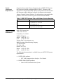
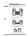
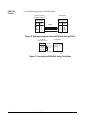
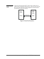
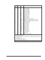
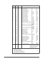
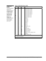
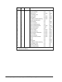
Metasys Connectivity Technical Manual 629.5 Metasys Integrator Section Application Note Issue Date 0703 APPLICATION NOTE Metasys Integrator MGE UPS Systems Application lntroduction 3 Application Details 3 Component Requirements 5 Vendor Contact Information 6 Design Considerations 7 Cable Connections 9 Cable Pinouts 9 Connecting the Cable 11 Metasys Integrator Setup 13 Point Mapping Tables 15 Unitary, Parallel, and Static Switch Devices 15 Comet UPS Points 19 Metasys Network Setup 22 Mapping to a CS Object 22 Custom Integration 24 © 2003 Johnson Controls, Inc. Code No. LIT-6295377 1 www.johnsoncontrols.com 2 Metasys Integrator—Metasys Integrator MGE UPS Systems Application lntroduction This document explains the Metasys Integrator MGE UPS Systems application. Use this document with the Metasys Integrator technical bulletins in the Metasys Connectivity Technical Manual (FAN 629.5), which provide information on installing and commissioning the Metasys Integrator unit. For information pertaining to MGE UPS Systems equipment, see applicable MGE UPS Systems documentation (obtainable from your MGE UPS service representative). Application Details The Metasys Integrator unit allows MGE UPS Systems equipment to become an integral part of the Metasys and Metasys Companion Networks. Once an EPS-6000 or an EPS-3000/COMET is connected to Metasys or Companion Networks via the Metasys Integrator unit, their data is available to the full complement of Metasys Building Automation System (BAS) features, including Change-of-State (COS) monitoring, alarm notification, scheduling, trend, and totalization. Up to 28 EPS-6000 or 255 EPS-3000/COMET devices can be connected to each vendor port of the Metasys Integrator unit, for a total of 56 EPS-6000 or 510 EPS-3000/COMET Uninterruptible Power Supplies (UPSs) on a two-port Metasys Integrator unit. Scan time may be unacceptable if the maximum number of devices is defined. Figure 1 shows MGE UPS Systems and Metasys integration. Figure 2 shows MGE UPS Systems and Metasys Companion integration. The Metasys Integrator unit supports the following MGE UPS Systems devices: • EPS-6000 Unitary UPS • EPS-6000 Parallel UPS • EPS-6000 Static Switch Cabinet • EPS-3000/COMET UPS Metasys Integrator—Metasys Integrator MGE UPS Systems Application 3 N1 LAN EPS-6000 or EPS-3000/ COMET Device Standard NCU RS-232 or RS-485 Metasys Integrator or EPS-6000 Device 50 ft maximum to Converter RS-232 to RS-485 Converter UNT EPS-6000 or EPS-3000/ COMET Device Multiple Devices per Port N2 Bus MGE1 Note: If you use a UPM enclosure, you must install the Metasys Integrator 300 Series in a two high enclosure (EN-EWC25-0) rather than a one high enclosure (EN-EWC13-0) as shown in the figures in this application note. Figure 1: MGE UPS Systems and Metasys Integration Panel Unit Workstation EPS-6000 or EPS-3000/ COMET Device RS-232 or or RS-485 Metasys Integrator 50 ft maximum to Converter RS-232 to RS-485 Converter N2 Bus EPS-6000 Device EPS-6000 or EPS-3000/ COMET Device Multiple Devices per Port MGEcomp Note: If you use a UPM enclosure, you must install the Metasys Integrator 300 Series in a two high enclosure (EN-EWC25-0) rather than a one high enclosure (EN-EWC13-0) as shown in the figures in this application note. Figure 2: MGE UPS Systems and Metasys Companion Integration 4 Metasys Integrator—Metasys Integrator MGE UPS Systems Application Component Requirements To integrate MGE UPS Systems, you need the following: • properly installed MGE UPS Systems with appropriate Communication Interface Option (RS-232 or RS-485) • B&B RS-232 to RS-485 converter (485 TBLED) with power supply (if necessary) • cables and connectors for connecting the converter to MGE UPS Systems • Metasys Integrator unit • N2 Bus (for connecting the Metasys Integrator unit to the Metasys or Companion Network) • portable PC for downloading vendor communication tables (.VCT files) and network setup information, and for running diagnostics • cable for connecting portable PC to the Metasys Integrator unit • the correct vendor communication table (.VCT file) to download into the Metasys Integrator unit (supplied on CD-ROM) • already installed communication trunk (RS-485) for the MGE UPS Systems equipment This document describes the RS-232 cable and the vendor communication tables. MGE UPS Systems documentation describes their equipment. The remaining components are described in the Metasys Integrator technical bulletins. Metasys Release Requirements Metasys Companion Release Requirements To integrate MGE UPS Systems equipment into the Metasys Network, you need: • Metasys OWS software Release 9.0 or higher • Metasys Integrator software/firmware Release 9.0 or higher To integrate MGE UPS Systems equipment into the Metasys Companion Network, you need: • Metasys Companion Release 7.0 or higher • Metasys Integrator software/firmware Release 9.0 or higher Metasys Integrator—Metasys Integrator MGE UPS Systems Application 5 Vendor Component Requirements Integration between the Metasys Integrator unit and MGE UPS Systems has been tested with the equipment listed in Table 1. Changes to this equipment or integration of MGE UPS Systems products not discussed in this document require additional software development and testing by Johnson Controls Systems Products. For information on integrating other products, refer to the Custom Integration section in this document. Table 1: MGE UPS Systems Part and Software Version Numbers Vendor Contact Information MGE Product Firmware Version EPS-6000 PAJO Board, Rev. C1 and C3 Acq EPROM, Rev. G0 and H0 Com EPROM, Rev. J0 EPS-3000/COMET PAJO Board, Rev. C0 Acq Firmware, Rev. B3 and B5 MGE UPS Systems, Inc. 1660 Scenic Avenue Costa Mesa, CA 92626 Technical Support: Phone: (800) 438-7373 FAX: (714) 434-7645 Internet: http://www.mgeups.com B&B Electronics Manufacturing Company 707 Dayton Road P.O. Box 1040 Ottawa, IL 61350 Phone: (815) 433-5100 FAX: (815) 433-5104 The following documentation is available from your MGE UPS Systems representative: • All EPS-6000 products: - • All EPS-3000/COMET products: - 6 GTC Link Communications Interface User Manual Comet J-BUS Communications System Metasys Integrator—Metasys Integrator MGE UPS Systems Application Design Considerations When integrating MGE UPS Systems equipment, consider the following: • All MGE UPS Systems equipment must be set up and running properly before attempting to integrate with Metasys or Companion Networks. (The MGE UPS Systems representative is responsible for configuration of MGE UPS Systems equipment.) • Make sure each UPS baud rate is set to 9600. (The MGE UPS Systems representative is responsible for setting the baud rate.) • Each UPS must have a valid address and the address for each UPS is a unique communication address. Do not use Address 0. • RS-232 cable distance between the Metasys Integrator unit and the RS-232 to RS-485 converter can be a maximum of 50 feet. • Cable distance between the converter and the last UPS can be a maximum of 4000 feet. • The appropriate communication option package must be present in UPS equipment. Verify the installation of this option with your local MGE UPS Systems representative. Metasys Integrator—Metasys Integrator MGE UPS Systems Application 7 8 Metasys Integrator—Metasys Integrator MGE UPS Systems Application Cable Connections Cable Pinouts When connecting to an RS-485 converter, use the following cable pinouts for the Metasys Integrator unit to the converter: Vendor Port A or B on Metasys Integrator RS-232 Port on Converter RS-485 TBLED DB-9 Female DB-25 Male Signal Pin DCD RD TD DTR GND DSR RTS CTS 1 2 3 4 5 6 7 8 RS-232 Pin Signal 8 3 2 20 7 6 4 5 DCD RD TD DTR GND DSR RTS CTS (50 ft maximum) Set converter jumpers to Echo Off and Control RTS. MGE2 Figure 3: Metasys Integrator to Converter EPS3000/COMET Pinouts Use the following pinouts for the EPS-3000/COMET: Vendor Port A or B on Metasys Integrator PAJO-XM2 DB-9 Female DB-9 Male Signal Pin FG RD TD GND 1 2 3 5 RS-232 Pin Signal 1 3 2 5 FG TD RD GND (50 ft maximum) MGE6 Figure 4: Metasys Integrator to EPS-3000/COMET Using RS-232 RS-232 to RS-485 Converter Signal TD (A) TD (B) RD (A) RD (B) JOJO-XM2 DB-9 Male Signal RS-485 4 and 5 8 and 9 L+ L- Note: Contact MGE UPS for EOL requirements. MGE9 Figure 5: Converter to EPS-3000/COMET Using Two Wires Metasys Integrator—Metasys Integrator MGE UPS Systems Application 9 EPS-6000 Pinouts Use the following pinouts for the EPS-6000: Vendor Port A or B on Metasys Integrator RAUZ-XM097 DB-9 Female DB-25 Female Signal Pin FG RD TD GND 1 2 3 5 RS-232 Pin Signal 1 2 3 7 FG RD TD GND (50 ft maximum) MGE3 Figure 6: Metasys Integrator Unit to EPS-6000 Using RS-232 RS-232 to RS-485 Converter Signal TD (A) TD (B) RD (A) RD (B) RS-485 RAUZ-XR11 Terminal Signal 4 or 8 2 or 6 L+ L- Note: Contact MGE UPS for EOL requirements. MGE5 Figure 7: Converter to EPS-6000 Using Two Wires 10 Metasys Integrator—Metasys Integrator MGE UPS Systems Application Connecting the Cable Connect the female end of the RS-232 cable to either Vendor Port A or Vendor Port B on the Metasys Integrator unit. Connect the other end to the RS-232 port on the MGE UPS Systems equipment or connect the other end to the RS-232 to RS-485 converter. EPS-3000 or EPS-6000 or Converter Metasys Integrator Vendor Port A or B RS-232 Cable RS-232 Connector MGE7 Figure 8: Port-to-Port Connection Metasys Integrator—Metasys Integrator MGE UPS Systems Application 11 12 Metasys Integrator—Metasys Integrator MGE UPS Systems Application Metasys Integrator Setup To set up the Metasys Integrator unit, use a portable PC connected to Metasys Integrator Terminal Port. Metasys Integrator setup involves: • downloading the correct vendor communication table (.VCT file) • setting up the ports • setting up the network addressing It is necessary to download a .VCT file only once, even if more than one device is referencing the file. The following table provides information specific to the MGE UPS Systems applications. For detailed procedures, see the Metasys Integrator technical bulletins. Table 2: Metasys Integrator Setup for MGE UPS Systems Vendor Communication Table (.VCT File) Unitary, Parallel, and Static Switch MGEUPS.VCT Comet MGECOMET.VCT Port Setup Baud Rate 9600 Word Length 8 Stop Bits 1 Parity None Interface RS-232 or RS-485 (If using RS-485, refer to the Cable Connections section of this document.) Network Setup Vendor Address EPS-3000/COMET 20, 28, 30 . . . F0, F8 (hex value only) 1-FF (hex) Timeout Value 1000 ms Poll Delay 55 ms EPS-6000 Performance Guide Approximate Scan Time (For a single N2 address) 2 seconds Metasys Integrator—Metasys Integrator MGE UPS Systems Application 13 14 Metasys Integrator—Metasys Integrator MGE UPS Systems Application Point Mapping Tables Unitary, Parallel, and Static Switch Devices To get the hardware reference for mapping points to a CS object (via the software model), combine the NPT (Network Point Type) and NPA (Network Point Address). For example, the hardware reference for the Current Phase 3 Mains 1 point is AI3. Table 3 shows the points available for mapping in the Unitary, Parallel, and Static Switch devices. Table 3: Unitary, Parallel, and Static Switch Devices NPT1 NPA Unit Description AI AI AI AI AI AI AI AI AI AI AI AI AI AI AI AI AI AI AI AI AI AI AI AI AI AI AI AI AI AI AI AI AI AI 1 2 3 4 5 6 7 8 9 10 11 12 13 14 15 16 17 18 19 20 21 22 23 24 25 26 27 28 29 30 31 32 33 34 A A A A A A A A A A A A A Current Phase 1 Mains 15 Current Phase 2 Mains 15 Current Phase 3 Mains 15 Current Phase 1 Invert5 Current Phase 2 Invert5 Current Phase 3 Invert5 Current Phase 1 Mains 24 Current Phase 2 Mains 24 Current Phase 3 Mains 24 Current Phase 1 Load Current Phase 2 Load Current Phase 3 Load Current Battery (if battery is installed)5 % Load % Peak Load Phase 1 % Peak Load Phase 2 % Peak Load Phase 3 U12 Volt Mains 14 U23 Volt Mains 14 U31 Volt Mains 14 U1N Inverter Volt5 U2N Inverter Volt5 U3N Inverter Volt5 U12 Inverter Volt5 U23 Inverter Volt5 U31 Inverter Volt5 U1N Volt Main 24 U2N Volt Main 24 U3N Volt Mains 24 U12 Volt Mains 24 U23 Volt Mains 24 U31 Volt Mains 24 U1N Load Voltage U2N Load Voltage 1 2 4 5 2 V V V V V V V V V V V V V V V V V Network Point Type Network Point Address Not available for Parallel UPS. Not available for Static Switch UPS. Metasys Integrator—Metasys Integrator MGE UPS Systems Application 15 Continued on next page . . . 16 Metasys Integrator—Metasys Integrator MGE UPS Systems Application NPT1 (Cont.) 2 NPA Unit Description AI AI AI AI AI AI AI AI AI AI AI AI AI AI AI AI AI AI AI AI AI AI AI AI AI AI AI 35 36 37 38 39 40 41 42 43 44 45 46 47 48 49 50 51 52 53 54 55 56 57 58 59 60 61 V V V V V Hz Hz Hz Hz V A Min DegC DegF A kW kW kW kW kVA kVA kVA kW kVA U3N Load Voltage U12 Load Voltage U23 Load Voltage U31 Load Voltage U Battery Voltage5 Frequency Mains 15 Frequency Inverter5 Frequency Mains 24 Frequency Load U Battery Voltage5 I Battery Current5 Battery Backup Time (if installed)5 Battery Room Temperature Deg C3 (if installed)5 Battery Room Temperature Deg F3 (if installed)5 Current Rated Load Power Rated Load P1 (Load Active) P2 (Load Active) P3 (Load Active) S1 (Load Active) S2 (Load Active) S3 (Load Active) P (Load Active) S1 (Load Apparent) % Inverter Load Power Factor Battery Room Temperature 1 2 3 4 5 DegF Network Point Type Network Point Address Duplicate points are shown in different units. This allows the Metasys Network to use either set of units. Not available for Parallel UPS. Not available for Static Switch UPS. Continued on next page . . . Metasys Integrator—Metasys Integrator MGE UPS Systems Application 17 NPT1 (Cont.) 2 BI BI BI BI BI BI BI BI BI BI BI BI BI BI BI 1 2 3 4 5 6 7 8 9 10 11 12 13 14 15 BI BI BI BI BI BI BI BI BI BI BI BI BI BI BI NPA 1 2 4 5 6 18 Description 31 Batt Circuit Brkr5 0-open Batt Discharging5 0-no Minimum Battery Volt5 0-no 5 Low Batt Shutdown 0-no Batt High Temperature5 0-normal Mains 1 Voltage5 0-normal Batt Room Ventilate5 0-normal 5 Battery Charging 0-no Rect Charger Status5 0-off Major Rect-Chrg Fit5 0-normal 5 Mains 1 Input Sw 0-open Emergency Off Sw6 0-inactive Rect-Chgr Input Volt5 0-normal 5 Rect-Chgr Input Freq 0-normal Grad Rect-Chgr Shut (if battery installed)5 0-inactive EngGenSet Curr Lim (if battery installed)5 0-inactive Batt Current Limit (if battery installed)5 0-inactive Battery Equalization (if battery installed)5 0-inactive 5 Operation on Engine 0-inactive System Normal 0-no Unsafe Operation 0-safe System Downgraded 0-no Inverter Connected 0-no Contactor K2S (only static switch > 800K)6 0-open Mains 2 Input Switch4 0-open Maintenance Bypass Sw4 0-open Q5N Inverter Output Sw 0-open Static Switch Status4 0-open Battery Installed5 0-no Battery Temperature Sensor Installed5 0-no Inverter K3N Contactor 0-open 1 Inverter Type @200 16 17 18 19 20 21 22 23 24 25 26 27 28 29 30 BI ADI Unit Network Point Type Network Point Address Not available for Parallel UPS. Not available for Static Switch UPS. Only available for Static Switch UPS. Metasys Integrator—Metasys Integrator MGE UPS Systems Application 1-closed 1-yes 1-yes 1-yes 1-alarm 1-alarm 1-alarm 1-yes 1-on 1-alarm 1-closed 1-active 1-alarm 1-alarm 1-active 1-active 1-active 1-active 1-active 1-yes 1-unsafe 1-yes 1-yes 1-closed 1-closed 1-closed 1-closed 1-closed 1-yes 1-yes 1-closed 0-Unitary 1-Parallel without Static Switch 2-Parallel with Static Switch 3-Static Switch Cubicle Comet UPS Points To get the hardware reference for mapping points to a CS object (via the software model), combine the NPT (Network Point Type) and NPA (Network Point Address). For example, the hardware reference for the Current Phase 3 Mains 2 point is AI6. Table 4: EPS-3000/Comet UPS NPT1 NPA Unit Description AI AI AI AI AI AI AI AI AI AI AI AI AI AI AI AI AI AI AI AI AI AI AI AI AI AI 1 2 3 4 5 6 7 8 9 10 11 12 13 14 15 16 17 18 19 20 21 22 23 24 25 26 A A A A A A A A A V V V V V V V V kVA Current Phase 1 Inverter Current Phase 2 Inverter Current Phase 3 Inverter Current Phase 1 Mains 2 Current Phase 2 Mains 2 Current Phase 3 Mains 2 Current Phase 1 Load Current Phase 2 Load Current Phase 3 Load U Mains 1 V1 Inverter V2 Inverter V3 Inverter U Mains 2 V1 Load V2 Load V3 Load S Apparent Power % Load % Rated Load Frequency Inverter Frequency Mains 2 Frequency Load Number of Times on Battery Power U Battery Battery Backup Time 1 2 2 Hz Hz Hz # V Min Network Point Type Network Point Address Continued on next page . . . Metasys Integrator—Metasys Integrator MGE UPS Systems Application 19 NPT1 (Cont.) 2 BI BI BI BI BI BI BI BI BI BI BI BI BI BI BI BI BI BI BI BI BI BI BI BI BI BI BI 1 2 3 4 5 6 7 8 9 10 11 12 13 14 15 16 17 18 19 20 21 22 23 24 25 26 27 1 2 20 NPA Unit Description Mains 1 Voltage Chopper Operation Battery Circuit End of Battery Time Charger Status Check Battery Low Battery Shutdown Warning Charger Operating Status Peak Overload Inverter Overload Inverter Operating Status Inverter Thermal Overload K3N Contactor Status Inverter Connected Mains 2 Voltage Mains 2 Frequency Mains 2/Inverter Phase Shift Phase Rotation Mains 2 Overload Mains 2 Thermal Overload Normal Danger Downgraded Low Battery Shutdown Warning End of Battery Time Operating on Battery Battery Valid Indicator Network Point Type Network Point Address Metasys Integrator—Metasys Integrator MGE UPS Systems Application 0-normal 0-off 0-normal 0-no 0-normal 0-normal 0-normal 0-off 0-no 0-no 0-off 0-normal 0-open 0-no 0-normal 0-normal 0-normal 0-normal 0-normal 0-normal 0-no 0-no 0-no 0-no 0-no 0-no 0-no 1-alarm 1-on 1-alarm 1-yes 1-alarm 1-alarm 1-alarm 1-on 1-alarm 1-alarm 1-on 1-alarm 1-closed 1-yes 1-alarm 1-alarm 1-alarm 1-alarm 1-alarm 1-alarm 1-yes 1-alarm 1-alarm 1-alarm 1-yes 1-yes 1-yes Metasys Integrator—Metasys Integrator MGE UPS Systems Application 21 Metasys Network Setup Metasys Network setup is described in the Metasys Integrator technical bulletins. This section contains details specific to MGE UPS Systems applications. Mapping to a CS Object Table 5: Software Model and CS Object Definition Application Software Model Display Attribute (on Tables and Models CD-ROM) (recommended) NT Command Attribute Unitary MGEUPS_U.DDL AI1 (recommended) AI1 Parallel MGEUPS_P.DDL AI1 AI1 Static Switch MGEUPS_S.DDL AI1 AI1 Comet MGECOMET.DDL AI1 AI1 * 22 For the NT Command attribute, use the same attribute as the Display attribute. However, since the points are not commandable, you will not be able to command the attribute. (This must be defined because the NT Command attribute cannot be null.) Metasys Integrator—Metasys Integrator MGE UPS Systems Application Metasys Integrator—Metasys Integrator MGE UPS Systems Application 23 Custom Integration For information on integrating products that are not discussed in this document, first refer to the Metasys Compatible Global Catalog, an online list of released Connectivity products. If this list does not provide the information you require, consider using the System Integration Project Data Sheet to request a custom contract from the System Integration Team. Both the Metasys Compatible Global Catalog and the System Integration Project Data Sheet can be accessed from The Advisor by performing the following steps: 1. Click on the Systems Products button located on the left side of The Advisor home page. 2. Click on the Product Literature link. 3. Click on the Manuals-FANS link. 4. Click on the 629.0 Metasys Connectivity Sales Resource Manual link. 5. Find the System Integration Project Data Sheet link in the Table of Contents. Click on this link to view an online copy of the System Integration Project Data Sheet, or click on the Metasys Compatible Global Catalog link below it to view a list of released Connectivity products. The System Integration Project Data Sheet (LIT-6290052) can also be found in the Metasys Connectivity Sales Resource Manual (FAN 629). If you need further assistance, contact the Johnson Controls Field Support Center. 24 Metasys Integrator—Metasys Integrator MGE UPS Systems Application Notes Controls Group 507 E. Michigan Street P.O. Box 423 Milwaukee, WI 53201 www.johnsoncontrols.com FAN 629.5 Metasys Connectivity Technical Manual Metasys Integrator Release 9.0 Printed in U.S.A. Metasys Integrator—Metasys Integrator MGE UPS Systems Application 25