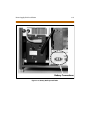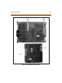
1
Feature Package 3
TRIAD 1/2/3
Installation
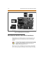
a new dimension in business communications
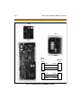
STARPLUSTM Triad 1/2/3TM
Installation Manual
Part Number: 8050-12
Issue 3.2 - March 2001
Issue
Release Date
2
8-99
Changes
Feature Package 2 {FP2} enhancements have been added.
Manual content contains extensive revisions.
2.1
12-99
Manual content has been revised.
3
5-00
Manual content has been reformatted.
3.1
8-00
Manual content has been revised to clarify Feature Package 3.
3.2
3-01
Manual content has been revised for correctness and clarity.
LIFE SUPPORT APPLIC ATIONS POLICY
VODAVI Communications Systems products are not authorized for and should not
be used within Life Support applications. Life Support systems are equipment
intended to support or sustain life and whose failure to perform when properly used
in accordance with instructions provided can be reasonably expected to result in
significant personal injury or death.
VODAVI Communications Systems warranty is limited to replacement of defective
components and does not cover injury to persons or property or other
consequential damages.
Copyright © 2001 VODAVI Technology, Inc.
All Rights Reserved
This material is copyrighted by VODAVI Technology, Inc., and may be duplicated by
Authorized Dealers only. Any unauthorized reproductions, use or disclosure of this
material, or any part thereof, is strictly prohibited and is a violation of the Copyright
Laws of the United States (17 U.S.C. Section 101 et. seq.).
VODAVI reserves the right to make changes in specifications at any time and without
notice. The information furnished by VODAVI in this material is believed to be accurate
and reliable, but is not warranted to be true in all cases.
STARPLUS and TRIAD™ are Registered trademarks of VODAVI Technology, Inc.
mlj/2001
Contents
1
Introduction
Regulatory Information (U.S.A.) ...................................................................... 1-3
Telephone Company Notification .......................................................... 1-3
Incidence of Harm ........................................................................................ 1-4
Changes in Service ....................................................................................... 1-4
Maintenance Limitations ........................................................................... 1-4
Hearing Aid Compatibility ........................................................................ 1-4
UL/CSA Safety Compliance ....................................................................... 1-4
Notice of Compliance ................................................................................. 1-5
Toll Fraud Disclaimer .......................................................................................... 1-5
2
Triad 1/2 System Installation
Introduction ........................................................................................................... 2-3
Site Preparation .................................................................................................... 2-4
General Site Considerations ..................................................................... 2-4
Back-Board Installation .............................................................................. 2-5
Verify On-Site Equipment .......................................................................... 2-5
KSU & Power Supply (PSU) Installation ........................................................ 2-8
Mounting the Triad 1 Basic KSU .............................................................. 2-8
KSU and Power Supply (PS) Installation ...................................................... 2-11
Mounting the Triad 2 Basic KSU .............................................................. 2-11
Mounting the Expansion KSU (EKSU) .................................................... 2-14
Ring Generator Installation (RGU) ................................................................. 2-16
Power Supply Unit Installation ....................................................................... 2-18
KSU Grounding ..................................................................................................... 2-20
Power Line Surge Protection ........................................................................... 2-21
Lightning Protection ................................................................................... 2-21
KSU AC Power Plug ...................................................................................... 2-21
PCB Installation ..................................................................................................... 2-22
PCB Handling & General Installation ..................................................... 2-22
Main Processor Board (MPB) Installation .................................................... 2-24
Phase Lock Loop Unit (PLLU) ................................................................... 2-26
Modem Unit (MODU) .................................................................................. 2-27
Miscellaneous Interface Unit (MISU) Installation ..................................... 2-29
ii
March 2001
Installing the Serial Interface Unit (SIU) ................................................ 2-31
CO/PBX Connections .......................................................................................... 2-33
Loop Start CO Interface Board (LCOB) .................................................. 2-33
DID Interface Board (DIDB) ....................................................................... 2-36
T-1 Interface Board (T1IB) .......................................................................... 2-39
Primary Rate Interface Board (PRIB) ....................................................... 2-48
Basic Rate Interface Board (BRIB) ............................................................ 2-49
ISDN and T1 Clocking ................................................................................. 2-52
Station Connections ........................................................................................... 2-57
Electronic Telephone Interface Board (ETIB) ...................................... 2-57
Single Line Interface Board (SLIB) ........................................................... 2-60
Digital Telephone Interface Board (DTIB) ............................................ 2-64
System Wiring ....................................................................................................... 2-67
Battery Back-Up Wiring Installation ....................................................... 2-67
MPB and SIU RS232C Port Wiring ........................................................... 2-68
MISU Wiring .................................................................................................... 2-69
Station Wiring ................................................................................................ 2-69
Wall Mounting the Electronic Telephone ................................................... 2-73
Wall Mounting the Digital Telephone .......................................................... 2-74
Headset Installation ............................................................................................ 2-75
Caller ID Interface Unit Installation ............................................................... 2-75
Selecting the Cable ...................................................................................... 2-75
Programming the KSU ................................................................................ 2-77
3
Triad 3 System Installation
Introduction ........................................................................................................... 3-3
Site Preparation .................................................................................................... 3-3
General Site Considerations ..................................................................... 3-3
Back-Board Installation .............................................................................. 3-4
Verify On-Site Equipment .......................................................................... 3-5
KSU & Power Supply (PSU) Installation ........................................................ 3-7
Mounting the Basic KSU ............................................................................. 3-7
Mounting the Expansion Cabinet (EKSU1) .......................................... 3-8
Mounting the Expansion Cabinet (EKSU2) .......................................... 3-9
Ring Generator Installation (RGU) ................................................................. 3-11
KSU Grounding ..................................................................................................... 3-12
March 2001
Power Supply Unit Installation ....................................................................... 3-14
AC/DC (PS-10A or PS-15A) ........................................................................ 3-14
DC/DC (with BCU & 48VU) ......................................................................... 3-16
Battery Back-up Wiring Installation ....................................................... 3-24
Power Line Surge Protection ................................................................... 3-26
Lightning Protection ................................................................................... 3-26
KSU AC Power Plug ...................................................................................... 3-26
PCB Installation ..................................................................................................... 3-27
PCB Handling & General Installation ..................................................... 3-27
Main Processor Board (MPB) Installation .................................................... 3-28
Serial Interface Unit (SIU2) ........................................................................ 3-31
Phase Lock Loop Unit (PLLU) ................................................................... 3-32
Memory Expansion Unit (MEMU) ........................................................... 3-33
Program Module Unit (PMU) .................................................................... 3-33
Miscellaneous Interface Unit (MISU) Installation ..................................... 3-34
Power Failure Transfer Unit (PFTU) ........................................................ 3-37
CO/PBX Connections .......................................................................................... 3-40
Loop Start CO Trunk Board (LCOB)) ....................................................... 3-40
Ground Start CO Trunk Board (GCOB) .................................................. 3-43
DID Trunk Board (DIDB) ............................................................................. 3-46
T-1 Interface Board (T1IB) .......................................................................... 3-49
Primary Rate Interface Board (PRIB) ....................................................... 3-58
Basic Rate Interface Board (BRIB) ............................................................ 3-64
Basic Rate Interface Expansion Board (BRIB-E) .................................. 3-67
ISDN and T1 Clocking ................................................................................. 3-68
Station Connections ........................................................................................... 3-72
Electronic Telephone Interface Board (ETIB) ...................................... 3-72
Single Line Interface Board (SLIB) ........................................................... 3-75
Digital Telephone Interface Board (DTIB) ............................................ 3-80
Station Wiring ....................................................................................................... 3-84
Wall Mounting the Electronic Telephone ................................................... 3-88
Wall Mounting the Digital Telephone .......................................................... 3-89
Headset Installation ............................................................................................ 3-90
Caller ID Interface Unit Installation ............................................................... 3-90
Selecting the Cable ...................................................................................... 3-90
Programming the KSU ................................................................................ 3-92
iii
iv
4
March 2001
System Check-Out
Preliminary Procedures ..................................................................................... 4-3
Power Up Sequence ........................................................................................... 4-3
5
Maintenance and Troubleshooting
System Programming and Verification ........................................................ 5-3
Telephone and Terminal Troubleshooting ................................................ 5-4
Keyset Self Test ..................................................................................................... 5-4
Keyset LCD/LED Test ................................................................................... 5-5
Keyset Button Test ....................................................................................... 5-5
DSS LED/Button Test ................................................................................... 5-6
Key Telephones/Terminals ........................................................................ 5-7
Single Line Telephones .............................................................................. 5-8
DSS/DLS Console .......................................................................................... 5-8
CO Line Card Functions ..................................................................................... 5-9
System Functions ................................................................................................ 5-11
Miscellaneous Functions ................................................................................... 5-14
Station Card Functions ...................................................................................... 5-15
Remote Maintenance ......................................................................................... 5-16
Overview .......................................................................................................... 5-16
Overview of Maintenance Commands ................................................. 5-16
Maintenance Password .............................................................................. 5-16
Exit Maintenance .......................................................................................... 5-17
System Configuration ................................................................................. 5-18
Station Configuration ................................................................................. 5-18
CO Line Configuration ................................................................................ 5-20
Event Trace Buffer ........................................................................................ 5-21
DTMF Receiver Trace ................................................................................... 5-22
Remote System Monitor ................................................................................... 5-22
Overview .......................................................................................................... 5-22
Monitor Password ........................................................................................ 5-23
Help Menu (?) ................................................................................................. 5-23
Dump Memory Data .................................................................................... 5-24
Event Trace Mode ......................................................................................... 5-24
Modify Memory Command ...................................................................... 5-26
Baud Rate Command .................................................................................. 5-27
March 2001
Exit the Monitor Mode ................................................................................ 5-27
v
vi
March 2001
vii
March 2001
Figures
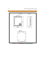
Triad 1 Default Card Layout ........................................................................................ 2-6
Triad 2 Key Service Unit (BKSU/EKSU) ..................................................................... 2-7
Triad 1 Unit Basic KSU Back w/Mounting Plate Extended ............................... 2-9
Triad 1 KSU Mounting Holes and Installation Layout ........................................ 2-10
Triad 2 Basic KSU Back w/Mounting Plate Extended ......................................... 2-12
Triad 2 KSU Mounting Holes and Installation Layout ........................................ 2-13
Expansion KSU Back w/Mounting Plate Extended ............................................. 2-14
Connection of BKSU and EKSU .................................................................................. 2-15
Ring Generator Installation ......................................................................................... 2-17
Installation of Power Supply Unit (PSU) ................................................................. 2-19
PCB Installation ............................................................................................................... 2-23
MPB w/PLLU and MODU Installation ...................................................................... 2-28
Talk Battery ....................................................................................................................... 2-29
MISU w/SIU Installation ................................................................................................ 2-32
LCOB w/DTRU Installation ........................................................................................... 2-35
DIDB w/DTRU Installation ............................................................................................ 2-38
T-1 Clock Connect Cable Installation (Multiple Cards) ...................................... 2-44
T-1 Clock Connect Cable Installation (Single Card) ............................................ 2-45
T1IB w/DTMF4_A Module Installation .................................................................... 2-47
PRIB (Primary Rate Interface Board) ......................................................................... 2-49
BRIB (Basis Rate Interface Board) .............................................................................. 2-50
Electronic Telephone Interface Board (ETIB) ........................................................ 2-59
SLIB w/MSGU and DTRU Module Installation ....................................................... 2-63
Digital Telephone Interface Board (DTIB) Installation ....................................... 2-66
Battery Back-Up Wiring ................................................................................................ 2-67
RS232 9-Pin Connector Wiring .................................................................................. 2-68
Digital Station Jack Wiring .......................................................................................... 2-69
Electronic Station Wiring ............................................................................................. 2-70
Single Line Telephone Wiring .................................................................................... 2-71
PFTU Wiring ...................................................................................................................... 2-72
Caller ID Cable Connections ....................................................................................... 2-76
CTI System Configuration ............................................................................................ 2-77
Electronic Key Telephone Wall Mounting ............................................................. 2-78
Digital Key Telephone Wall Mounting .................................................................... 2-79
March 2001
viii
SMDR Printout ................................................................................................................. 2-80
Basic Cabinet (BKSU) w/Expansion KSU (EKSU1/EKSU2) .................................. 3-6
BKSU Mounting Holes ................................................................................................... 3-8
Expansion Cabinet (EKSU2) Installation ................................................................. 3-10
Ring Generator Installation ......................................................................................... 3-11
KSU Grounding ................................................................................................................ 3-13
AC/DC Power Installation ............................................................................................ 3-15
Optional Battery Charging Unit (BCU) .................................................................... 3-17
DCCU and Optional BCU Installation ...................................................................... 3-18
Typical System Configurations .................................................................................. 3-20
Typical System Configurations .................................................................................. 3-21
Typical System Configurations .................................................................................. 3-22
Typical System Configurations .................................................................................. 3-23
Battery Back-Up Installation ....................................................................................... 3-25
MPB Daughter Boards Installation ........................................................................... 3-34
Talk Battery ....................................................................................................................... 3-35
MISU & PFTU Installation ............................................................................................. 3-39
LCOB w/DTMF-B Installation ...................................................................................... 3-42
GCOB w/DTMF-B Installation ..................................................................................... 3-45
DIDB w/DTMF-B Installation ....................................................................................... 3-48
T-1 Clock Connect Cable Installation (Multiple Cards) ...................................... 3-54
T-1 Clock Connect Cable Installation (Single Card) ............................................ 3-55
T1IB w/DTMF-A Module Installation ........................................................................ 3-57
PRIB (Primary Rate Interface Board) ......................................................................... 3-60
PRIB w/DTMF-A Module Installation ....................................................................... 3-63
BRIB (Basis Rate Interface Board) .............................................................................. 3-65
Electronic Telephone Interface Board (ETIB) ........................................................ 3-74
SLIB w/DTMF-A and MSG12 Installation ................................................................ 3-79
DTIB w/DTIB-E Installation .......................................................................................... 3-83
Digital Station Jack Wiring .......................................................................................... 3-84
Electronic Station Jack Wiring .................................................................................... 3-85
Single Line Telephone Wiring .................................................................................... 3-86
PFTU Wiring ...................................................................................................................... 3-87
Caller ID Cable Connections ....................................................................................... 3-91
Caller ID Cable Connections - Triad 3 SIU .............................................................. 3-91
CTI System Configuration ............................................................................................ 3-92
ix
March 2001
Electronic Key Telephone Wall Mounting ............................................................. 3-93
Digital Key Telephone Wall Mounting .................................................................... 3-94
SMDR Printout ................................................................................................................. 3-95
Maintenance Help Menu ............................................................................................. 5-17
Remote System Configuration .................................................................................. 5-18
Station Configuration ................................................................................................... 5-19
CO Line Configuration .................................................................................................. 5-20
Help Menu ......................................................................................................................... 5-23
Trace Mode Status .......................................................................................................... 5-24
Enable Event Trace ......................................................................................................... 5-26
Event Trace ....................................................................................................................... 5-27
x
March 2001
March 2001
xi
Tables
MPB Switch Positions .................................................................................................... 2-24
MISU Wiring ...................................................................................................................... 2-30
LCOB Wiring ..................................................................................................................... 2-34
DIDB Wiring ...................................................................................................................... 2-37
T-1 Board LEDS ................................................................................................................ 2-39
T-1 Ordering Information ............................................................................................ 2-40
T-1 Switch Positions ....................................................................................................... 2-40
Call Routing Criteria ....................................................................................................... 2-42
Call Routing Display Format ....................................................................................... 2-42
T-1 Ordering Specifications ........................................................................................ 2-43
ETIB Wiring ........................................................................................................................ 2-58
SLIB Wiring ........................................................................................................................ 2-60
DTIB Wiring ....................................................................................................................... 2-65
System Back-Up Duration ........................................................................................... 2-68
Power Consumption per Card ................................................................................... 3-19
System Back-Up Duration ........................................................................................... 3-24
MPB Dip Switch Functions .......................................................................................... 3-30
I/O Port RS232 Connections ....................................................................................... 3-30
MISU Wiring ...................................................................................................................... 3-36
Power Failure Transfer Unit (PFTU) Wiring ............................................................ 3-38
LCOB Wiring ..................................................................................................................... 3-41
GCOB Wiring ..................................................................................................................... 3-44
DIDB Wiring ...................................................................................................................... 3-47
T-1 Board LEDs ................................................................................................................. 3-49
T-1 Ordering Information ............................................................................................ 3-50
T-1 Switch Positions ....................................................................................................... 3-50
Call Routing Criteria ....................................................................................................... 3-52
Call Routing Display Format ....................................................................................... 3-52
PRIB Board LEDs .............................................................................................................. 3-58
PRI Ordering Information ............................................................................................ 3-59
Call Routing Criteria ....................................................................................................... 3-61
Call Routing Display Format ....................................................................................... 3-62
ETIB Wiring ........................................................................................................................ 3-73
SLIB Wiring ........................................................................................................................ 3-77
xii
March 2001
DTIB Wiring ....................................................................................................................... 3-82
Power Supply Tests ........................................................................................................ 4-4
Triad 3 DCCU Test Points ............................................................................................. 4-4
Flash Rates ........................................................................................................................ 5-5
Key Telephones/Terminals .......................................................................................... 5-7
Single Line Telephones ................................................................................................ 5-8
DSS/DLS Console ............................................................................................................ 5-8
CO Line Loop Start Interface Board (LCOB) ........................................................... 5-9
CO Line Ground Start Interface Board (GCOB) (Triad 3 only) .......................... 5-9
Direct Inward Dial Interface Board (DIDB) ............................................................. 5-10
PRIB Switches ................................................................................................................... 5-10
Master Processor Board (MPB) ................................................................................... 5-11
Memory Expansion Module Unit (MEMU) (Triad 3 only) .................................. 5-11
Modem Unit (MODU) .................................................................................................... 5-12
Program Module Unit (PMU) ...................................................................................... 5-12
Power Supply Unit (PSU) .............................................................................................. 5-12
Miscellaneous Interface Board (MISU) .................................................................... 5-13
DTMF Receiver Unit (DTRU, DTMF-A, DTMF-B) .................................................... 5-13
Ring Generator Unit (RGU) .......................................................................................... 5-14
Power Failure Transfer Unit (PFTU) .......................................................................... 5-14
Digital Key Terminal Interface Board (DTIB) .......................................................... 5-15
Single Line Interface Board (SLIB) w/MSGU .......................................................... 5-15
Event Trace Buffer Commands .................................................................................. 5-21
1
Introduction
This manual provides the information necessary to install and
maintain the STARPLUS Triad 1/2/3 Systems. The described features
are based on the current software release. If any of these features do
not work on your system, call your sales representative regarding
upgrading your system.
Regulatory Information (U.S.A.)
1-3
Regulatory Information (U.S.A.)
The Federal Communications Commission (FCC) has established rules
which allow the direct connection of the Triad 1/2/3 Systems to the
telephone network. Certain actions must be undertaken or understood
before the connection of customer provided equipment is completed.
Telephone Company Notification
Before connecting the Triad 1/2/3 Systems to the telephone network, the
local serving telephone company must be given advance notice of
intention to use customer provided equipment and provided with the
following information:
Telephone Numbers
The telephone numbers to be connected to the system.
Triad 1/2 Systems Information
The Ringer Equivalence Number also located on the KSU: 1.3B
The USOC jack required for direct interconnection with the telephone
network: RJ11C
Triad 3 System Information
The Ringer Equivalence Number also located on the KSU: 1.3B
The USOC jack required for direct interconnection with the telephone
network: RJ21X
FCC Registration Numbers
For systems configured as a key system: (button appearances)
DLPKOR-24039-KF-E
For systems configured as a Hybrid system: (dial access codes)
DLPKOR-24026-MF-E
1-4
Regulatory Information (U.S.A.)
Incidence of Harm
If the telephone company determines that the customer provided
equipment is faulty and possibly causing harm or interruption to the
telephone network, it should be disconnected until repairs can be made.
If this is not done, the telephone company may temporarily disconnect
service.
Changes in Service
The local telephone company may make changes in its communications
facilities or procedures. If these changes should affect the use of the Triad
1/2/3 Systems or compatibility with the network, the telephone company
must give written notice to the user to allow uninterrupted service.
Maintenance Limitations
Maintenance on the Triad 1/2/3 Systems is to be performed only by the
manufacturer or its authorized agent. The user may not make any
changes and/or repairs except as specifically noted in this manual. If
unauthorized alterations or repairs are made, any remaining warranty
and the software license for the system will be voided.
Hearing Aid Compatibility
All Triad 1/2/3 Digital Telephones are Hearing Aid Compatible, as defined
in Section 68.316 of Part 68 FCC Rules and Regulations.
UL/CSA Safety Compliance
The Triad 1/2/3 Systems have met all safety requirements and were found
be in compliance with the Underwriters Laboratories (UL) 1459. The Triad
1/2/3 Systems are authorized to bear the NRTL/C marking.
Toll Fraud Disclaimer
1-5
Notice of Compliance
The Triad 1/2/3 Systems comply with rules regarding radiation and radio
frequency emissions by Class A computing devices. In accordance with
FCC Standard 15 (Subpart J), the following information must be supplied
to the end user:
“This equipment generates and uses RF energy and if not installed and
used in accordance with the Instruction Manual, may cause interference
to Radio Communications. It has been tested and found to comply with
the limits fora Class A computing device, pursuanttoSubpart J of Part15
of the FCC Rules, which are designed to provide reasonable protection
against such interference, when operated in acommercial environment.
Operation of this equipment in a residential area is likely to cause
interference, in which case the user, at his own expense, will be required
to take whatever measures may be required to correct the interference.”
Toll Fraud Disclaimer
“While this device is designed to be reasonably secure against intrusions
from fraudulent callers, it is by no means invulnerable to fraud. Therefore,
no express or implied warranty is made against such fraud including
interconnection to the long distance network.”
“While this device is designed to be reasonably secure against invasion of
privacy, it is by no means invulnerable to such invasions. Therefore, no
express or implied warranty is made against unlawful or unauthorized
utilization which results in the invasion of one’s right of privacy.”
1-6
Toll Fraud Disclaimer
2
Triad 1/2 System
Installation
This chapter contains the basic system installation and wiring
instructions for the Triad 1/2 Systems, as well as how to install the
optional cards and units.
Introduction
2-3
Introduction
As with any sophisticated communications device, installation of the
Triad 1/2 Systems, requires the care and forethought of a competent
technician. To assure easy servicing and reliable operation, several factors
must be considered when planning the system installation. The
installation consists of these major steps:
Site Preparation
KSU and Power Supply (PS) Installation
PCB Installation
System Wiring
Keyset and Terminal Installation
Basic Installation Check-Out
System Programming and Verification
Installing the STARPLUS Triad 1/2 System is quick and efficient if these
installation instructions are followed.
2-4
Site Preparation
Site Preparation
General Site Considerations
The first step is to locate an acceptable site for the common equipment
(KSUs, boards, etc.). When locating a mounting site for the KSUs, the
following points must be considered.
The KSUs are designed for wall mounting and should not be
mounted directly to a masonry or plasterboard wall. It is
recommended that a 1/2 inch plywood back board be firmly
mounted to the wall, and the KSU and MDF, if other than the MDF, be
mounted to the back board.
The location must have access to a dedicated 110 Volt AC (±10%), 60
Hz, single-phase circuit with a circuit breaker or fuse rated at 15 amps.
A 3-wire (parallel blade grounded outlet should be within
approximately 6 feet of the lower left rear of the BKSU mounting.
The location must have access to a good earth ground, such as a
metallic cold water pipe with no non-metallic joints. The ground
source should be located as close as possible to the system.
The system should be located in an area which is well ventilated with
a recommended temperature range of 68°-78° F and a relative
humidity range of 5-60% (non condensing).
The system should be located within 25 feet of the telephone
company’s termination point. Also, the location should be within the
prescribed station loop lengths for all keysets and terminals. If
existing cabling is to be used, the location of existing cabling and
conduits should be considered.
Protection from flooding, flammable materials, excessive dust and
vibration.
The site should be away from radio transmitting equipment, arcwelding devices, copying machines and other electrical equipment
that are capable of generating electrical interferences. Operation of
this equipment in a residential area is likely to cause interference in
which case the user, at their own expense, are required to take
whatever measures may be required to correct the interference.
Site Preparation
2-5
Back-Board Installation
A wooden back-board is recommended for all installations and must be
installed when the location has masonry or plasterboard walls. A 1/2 inch
plywood material is sufficient for most installations. The back-board
should be mounted at a convenient height, about 3 feet above the floor
and bolted in a number of places to distribute the weight of the system.
Space should be available on the bottom side of the back-board for the
MDF cabling and for optional equipment such as a music source and
PFTU, etc. It is recommended the location of each major item be roughly
sketched on the back-board as an installation layout.
Verify On-Site Equipment
Once the equipment installation site has been identified and a dedicated
AC outlet, earth ground, and lighting and ventilation are available, verify
that all equipment required is on-site and has not been damaged during
shipment. Unpack the KSUs to assure there is no shipping damage. Note
that a mounting template is packed with each KSU and this template is
required later in the installation. Check that the type and quantity of
boards receive is correct and optional equipment and a Power Line Surge
Protector are on-site. Note that the individual boards should NOT be
unpacked at this time.
If any equipment is damaged or missing, notify the appropriate
personnel to correct the situation.
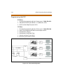
2-6
Site Preparation
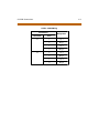
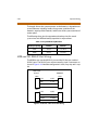
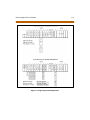
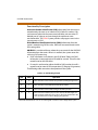
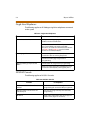
DEFAULT CARD LAYOUT
0
D
T
I
B
1
D
T
I
B
SLOTS
2
6
D
T
I
B
L
C
O
B
7
N
O
N
E
MPB
M
P
B
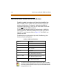
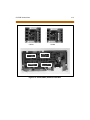
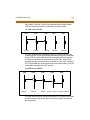
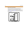
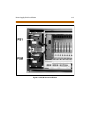
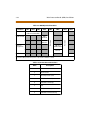
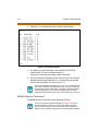
Figure 2-1: Triad 1 Default Card Layout
Site Preparation
2-7
DEFAULT CARD LAYOUT
0
1
2
3
4
5
D
T
I
B
D
T
I
B
D
T
I
B
D
T
I
B
L
C
O
B
L
C
O
B
SLOTS
6 7 MPB
L
C
O
B
N
O
N
E
M
P
B
8
9
N
O
N
E
N
O
N
E
10 11
N
O
N
E
N
O
N
E
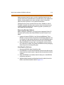
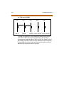
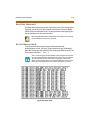
Figure 2-2: Triad 2 Key Service Unit (BKSU/EKSU)
In certain configurations, it is possible to not have all card slots utilized due to power
supplycapacities.Use the Configurator Programto calculate the correctconfiguration.
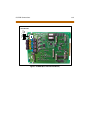
2-8
KSU & Power Supply (PSU) Installation
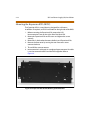
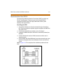
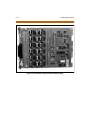
KSU & Power Supply (PSU) Installation
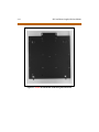
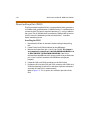
The Triad 1 System consists of a Basic KSU (BKSU) cabinet. The basic
exterior of the Triad 1 System is shown in Figure 2-2.
Mounting the Triad 1 Basic KSU
The Basic KSU is a metal frame cabinet designed for wall mounting.
Employing the KSU mounting template provided with the BKSU, mark
the location of the two screws to mount the BKSU. Again, the KSU must
NOT be mounted on a masonry or dry-wall surface, in this case a wooden
back-board is required. Refer to the next diagram for the distance
between mounting holes.
The BSKU is mounted with four #10 or larger, 1 ½ inch or longer screws.
1. Drill pilot holes in the two locations marked, insert the screws and
tighten leaving about ½ inch exposed.
2. Mount the Basic KSU on the screws and tighten the screws securely.
3. Remove the front cover by turning the two cover screws counter
clockwise.
4. Tilt and lift the cover to remove.
5. Insert the screws to the mounting holes of the BKSU and tighten the
screws as shown.
KSU & Power Supply (PSU) Installation
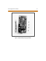
Figure 2-3: Triad 1 Unit Basic KSU Back w/Mounting Plate Extended
2-9
2-10
KSU & Power Supply (PSU) Installation
Figure 2-4: Triad 1 KSU Mounting Holes and Installation Layout
KSU and Power Supply (PS) Installation
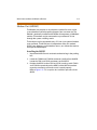
2-11
KSU and Power Supply (PS) Installation
The Triad 2 System consists of a Basic KSU (BKSU) and Expansion KSU
(EKSU). The basic exterior of the Triad 2 System is shown in Figure 2-2.
Mounting the Triad 2 Basic KSU
The Basic KSU is a metal frame cabinet designed for wall mounting.
Employing the KSU mounting template provided with the BKSU, mark
the location of the two screws to mount the BKSU. Again, the KSU must
NOT be mounted on a masonry or dry-wall surface, in this case a wooden
back-board is required. Refer to Figure 2-2 for the distance between
mounting holes.
The BSKU is mounted with four #10 or larger, 1 ½ inch or longer screws.
1. Drill pilot holes in the two locations marked, insert the screws and
tighten leaving about ½ inch exposed.
2. Mount the Basic KSU on the screws and tighten the screws securely.
3. Remove the front cover by turning the two cover screws counter
clockwise.
4. Tilt and lift the cover to remove.
5. Insert the screws to the mounting holes of the BKSU and tighten the
screws securely.
2-12
KSU and Power Supply (PS) Installation
Figure 2-5: Triad 2 Basic KSU Back w/Mounting Plate Extended
KSU and Power Supply (PS) Installation
Figure 2-6: Triad 2 KSU Mounting Holes and Installation Layout
2-13
2-14
KSU and Power Supply (PS) Installation
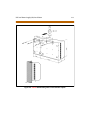
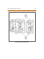
Mounting the Expansion KSU (EKSU)
The Expansion KSU is a metal housing designed for wall mount
installation. If required, an EKSU is mounted on the right side of the BKSU.
1. Before mounting the Expansion KSU, remove the KSU
Interconnection Cover on the right side of the Basic KSU.
2. Mount the Expansion KSU on the screws and tighten the screws
securely.
3. Mount the 2 side brackets between the Basic and Expansion KSUs.
4. Remove the front cover by turning the two front cover screws
counter clockwise.
5. Tilt and lift the cover to remove.
6. Interconnection is achieved via a amphenol type connector. No cable
is used to connect the BKSU and the EKSU together. Refer to
Figure 2-8.
Figure 2-7: Expansion KSU Back w/Mounting Plate Extended
KSU and Power Supply (PS) Installation
Figure 2-8: Connection of BKSU and EKSU
2-15
2-16
Ring Generator Installation (RGU)
Ring Generator Installation (RGU)
The Ring Generator Unit is needed in the BKSU where a SLIB is to be
installed, to provide ring voltage and Message Wait source power.
According to the installation site, two types of RGUs are available:
External and Internal.
The external RGU is mounted outside the KSU to the wall with the
two screws provided and is connected to the system backplane via
the CN12 (PCB lettering) connector.
The internal RGU is mounted inside the BKSU to the bottom side
panel with the two screws provided and is connected to the system
backplane via the CN12 (PCB lettering) connector.
Ring Generator Installation (RGU)
2-17
CN12 CONNECTOR
EXTERNAL RGU
INTERNAL
RGU
Internal RGU supports up to two (2) SLIB
Boards.
Beyond two boards requires the External
RGU in place of the Internal RGU.
Figure 2-9: Ring Generator Installation
2-18
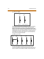
Power Supply Unit Installation
Power Supply Unit Installation
The Power Supply Unit provides power for the system boards and
telephones, converting AC voltage input to appropriate DC voltages.
Before Installation:
Assure that the AC plug connected to the BKSU is NOT plugged into
the AC outlet.
Place the PSU in the left most slot in the BKSU, aligning the card
guides with the PSU PCB and PSU frame flanges.
The PSU can operate from either 115 or 220 volts AC based on the setting
of the VTG Selector Switch on the lower front of the PSU.
If local AC is 110 volts, move the switch to the upper position to
display 115V.
If local AC is 220 volts, move the switch to the lower position to
display 220V.
Although, the Triad 2 System PSUs are equipped with power-line
transient protection, an external Power Line Surge Protector should be
installed at the AC outlet to give additional protection, especially during
violent thunderstorm activity. Refer to Lightning Protection.
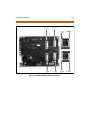
Power Supply Unit Installation
2-19
Triad 1
CARD
GUIDES
Triad 2
CARD
GUIDES
Figure 2-10: Installation of Power Supply Unit (PSU)
2-20
KSU Grounding
KSU Grounding
To ensure proper system operation and for safety purposes, a good earth
ground is required. A metallic COLD water pipe usually provides a reliable
ground. Carefully check that the pipe does not contain insulated joints
that could isolate the ground. In the absence of the COLD water pipe, a
ground rod or other source may be used.
A #14 insulated AWG or larger copper wire should be used between the
ground source and the KSU. The wire should be kept as short as possible,
it is recommended that the wire be no longer than 25 feet.
Grounding Instructions
1. Remove about 1½ inches of insulation from both ends. Attach one
end of the wire to the Ground Lug on the lower left side of the Basic
KSU by inserting the wire under the lug screw and tighten the screw
securely.
2. Attach the other end of the wire as appropriate to the ground source.
3. Take a DC resistance reading and an AC Volt reading between the
chassis ground point (cold water pipe) and AC ground (third wire AC
ground). The limit is 5V AC and 5 Ohms DC resistance. If a higher
reading is obtained, choose a different chassis ground point and
repeat this step until a suitable ground point is found.
Grounding to an electrical conduit is NOT considered a good
ground!
Power Line Surge Protection
2-21
Power Line Surge Protection
The AC outlet should be equipped with an additional power line
transient surge protection device. Systems using such devices are more
resistant to damage from power line surges than unprotected systems.
Power line surges often occur during switching operations and especially
during violent thunderstorm activity.
Installation of a surge protector meeting the specifications described in
the follow paragraph prevents or minimizes the damage resulting from
power line surges.
The isolation transformer/surge protector shall be a 15 amp self
contained unit that plugs into a standard grounded 117 VAC wall outlet.
The wall outlet must be designed to accept a 3-prong plug (2 parallel
blades and ground pin). The protector should be fast operating and
capable of protecting transients greater than 200 volts.
It is recommended that the AC outlet be equipped with an isolation
transformer/surge protection device that utilized MOV protection.
Lightning Protection
The system provides secondary protection per UL 1459 Specifications.
Primary protection circuitry is the installers responsibility and should be
installed per the National Electric Code (NEC).
KSU AC Power Plug
Before plugging the KSU power cord into the AC source, verify that the
Power switch on the AC/DC front panel is off.
Plug the KSU power cord into the AC outlet and turn the AC/DC Power
switch on. The red/green LED on the PSUs should illuminate.
2-22
PCB Installation
PCB Installation
PCB Handling & General Installation
All Boards SHOULD NOT be Installed or Removed with Power Applied.
Power must be turned off prior to insertion or removal of the PCBs.
The system PCBs contain digital circuitry which, while extremely reliable,
can be damaged by exposure to excessive static electricity. When
handling PCBs, a grounded wrist strap should be used to protect the
boards from static discharges. Also, use common sense when handling
PCBs. For example, do not place a PCB in locations where heavy objects
might fall on the PCB and damage components.
Only DTIB type stations can be used for Database programming.
Inserting a PCB
1. Hold the PCB by the injector tabs and, with the components facing
right, align the top and bottom edge of the PCB in the card guides.
2. Slide the card into the system and use the injectors to seat the PCB
firmly into the backplane connector.
Removing a PCB
Reverse the Inserting a PCB procedure. Installation method of PCB is
shown in Figure 2-11.
There is a ground tab located on the top and bottom of each PCB toward
the front end of the card. There is also a ground tab located to the right of
each card guide in each cabinet. Make sure when the PCBs are inserted
into the card guide and secured in their respective card slots, that the
ground tab on each card mates with the ground tab on each card guide.
This ensure a good ground potential to reduce RFI and EMI interference
possibilities.
PCB Installation
2-23
Figure 2-11: PCB Installation
2-24
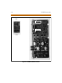
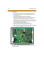
Main Processor Board (MPB) Installation
Main Processor Board (MPB) Installation
The MPB is installed in the right most PCB card slot (slot MPB) of the
BKSU. The MPB contains a lithium dry-cell to maintain memory and
real-time clock functions. The battery is soldered to the MPB and
connected to the circuitry by an On-Off DIP switch. Make sure the DIP
switch is ON before the MPB installation.
The MPB may be equipped with three daughter boards: A MEMU for
memory expansion, a MODU for modem access to the system, and a
PLLU for T-1 synchronization. Refer to Figure 2-12. The MEMU is not
utilized at this time.
The MPB also has an eight position dip switch. The following is the
function of each switch position:
Table 2-1: MPB Switch Positions
Switch 1
Not Used
Switch 2
Not Used
Switch 3
Not Used
Switch 4 Handshaking
ON: XOFF/XON
OFF: CTS/RTS
Switch 5
Not Used
Switch 6 Tests
ON: Execute H/W tests at start up
OFF: Skip H/W tests at start-up
Switch 7 Status
ON: Display start up status at start-up.
OFF: No start-up display status
Switch 8 DB Flush
ON: Flush the database
OFF: Retain the database
Use extra care when removing RS232 cables from the Triad 1/2/3 MPB or
SIU boards. Hold the MPB/MISU card in the card slot before removing the
RS232 cable.Failure toperformthis action mayresult intheMPB/MISU card
being pulled from its’ slot.
Main Processor Board (MPB) Installation
2-25
Before programming the system, switch 8 should be placed in the ON
position and power cycled off and on to initialize the system database to
default. Once the database has been initialized, switch 8 should be
placed in the OFF position so as to protect the database.
Software for the system is contained on two chips, labeled U1 and U3.
The MPB is shipped with these chips in place so you should not have to
install the software. However, if a software upgrade is purchased, you
must replace the existing chips.
Removing Existing Software
Before starting this procedure, you must have an Integrated Circuit (IC)
Extractor tool to remove the current EPROMs from the Printed Circuit
Board.
1. Locate and remove EPROMs U1 and U3 on the MPB board. These
EPROMs must be removed and replaced with EPROMs labeled U1 and
U3. Using the IC tool, gently pull upwards until the EPROM lifts free of
the socket. Be careful not to bend or break the pins of the EPROMs.
2. Place the EPROMs on a non-static, non-conductive surface until the
new software is installed. Then place the EPROMs into the packaging
tube and put this into the packing box.
Installing New Software
1. Remove the EPROMs from the packing tube.
2. Install EPROMs U1 and U3 onto the Master Processor Unit. Be sure the
notched end (end with cutout) is aligned with the notched end of the
socket(s).
3. When the EPROMS are installed, check for bent pins on the EPROMs
and correct any found.
4. With the lithium batteries and daughter boards installed, insert the
MPB in slot MPB of the BKSU. Refer to Figure 2-12.
2-26
Main Processor Board (MPB) Installation
Phase Lock Loop Unit (PLLU)
The Phase Locked Loop Unit (PLLU) is an option board which generates a
32.768MHz clock synchronized to 1.544MHz from the T-1 interface board
or internal clock. This board is required whenever a T-1 card is installed in
the system. The 32.768MHz clock is provided to CGMD on MPB. It consists
of a PLL circuit, PLL Monitoring circuit and clock (from T-1 interface
board) monitoring circuit.
Installing the PLLU
1. Unpack the PLLU from its antistatic conductive bag in the packing
box.
2. Locate CONN5 and CONN6 (outlined) on the MPB board.
3. Remove the jumper from pins 12 and 13 on CONN5. This jumper is
very important, so don’t lose it. LOSS OF JUMPER ON CONN5 12 &
13 WILL PREVENT SYSTEM FROM OPERATION. If the PLLU is
removed from the MPB board, this jumper needs to be put back onto
pins 12 and 13 of this connector or the MPB does not operate
properly.
4. Locate the CON1 and CON2 connectors on the PLLU board.
5. Position the PLLU so that CON2 and CON1 match up with CONN5 and
CONN6 respectively. Push the PLLU onto their respective connectors
and make sure the PLLU is seated correctly.
Refer to Figure 2-12. This completes the installation procedure for the
PLLU.
Main Processor Board (MPB) Installation
2-27
Modem Unit (MODU)
The Modem Unit provides an asynchronous modem for access to the
system database and fault reporting features from a remote site. The
Module is optionally installed on the MPB and incorporates a 2400 Baud
modem. The modem may be connected to a pre-selected CO Line
through the system switching matrix.
The local port may be connected to any CO Line via an external modem
or to a terminal. The MODU port is independent of the SIU standard
RS232C port, allowing system database access, etc. without the need to
interrupt the SMDR output.
Installing the MODU
1. Unpack the MODU from its antistatic conductive bag in the packing
box.
2. Locate the CONN9 and CONN10 connectors (outlined) on the MPB.
Locate the CON1 and CON2 connectors on the MODU.
3. Position the MODU so that CON2 and CON1 match up with CONN9
and CONN10 respectively on the MPB. Push the MODU onto their
respective connectors and make sure it is seated properly.
Refer to Figure 2-12. This completes the installation procedure for the
MODU.
2-28
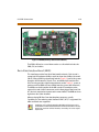
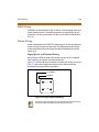
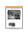
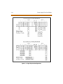
Main Processor Board (MPB) Installation
CON1
P
CON1
CON2
CONN6
CONN5
MODU
CONN10
CONN9
CON2
MPB
RS232C
TERMINAL
9 PIN
9 PIN
2 (TX)
2 (RX)
3 (RX)
3 (TX)
5 (GND)
5 (GND)
2 (TX)
3 (RX)
3 (RX)
2 (TX)
5 (GND)
5 (GND)
9 PIN
25 PIN
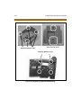
Figure 2-12: MPB w/PLLU and MODU Installation
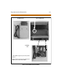
Miscellaneous Interface Unit (MISU) Installation
2-29
Miscellaneous Interface Unit (MISU) Installation
The Miscellaneous Unit (MISU) contains two External Music Sources
(MOH/BGM), an External paging port, and four dry contacts. Optionally,
the MISU is equipped with two serial interface ports by installing the
Serial Interface Unit (SIU) daughter board. The SIU should be installed if
more than two serial communication devices are to be connected to the
system. If required, install the SIU as shown in Figure 2-14.
When using CO Lines as additional music inputs, keep in mind that the
music source may require a talk battery in series with either TIP or Ring.
This talk battery boosts the signal level sufficiently so that the CO Line
interface can read the signal.
Music Source
KSU
Talk
Battery
Figure 2-13: Talk Battery
The MISU should be inserted into slot #7.
Use extra care when removing RS232 cables from the MPB or SIU boards.
Hold the MPB/MISU card in the card slotbefore removing the RS232 cable.
Failure to perform this action may result in the MPB/MISU card being
pulled from its’ slot.
The MISU consists of:
The External page ports are provided from the amphenol connector
on the front edge of the MISU. These ports are connected to
transformers, providing a 600 ohm impedance.
Music inputs are provided from the amphenol connector on the front
edge of the card.
Four independent relay contacts are provided through the amphenol
connector on the front edge of the MISU. These contacts are
controlled by software from entries in the system database. Control
signals are sent by the MPB. The output drives the relay coils,
controlling the state of the 1 amp, 24V relay contacts.
2-30
Miscellaneous Interface Unit (MISU) Installation
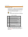
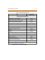
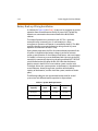
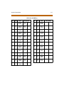
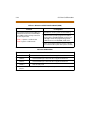
Table 2-2: MISU Wiring
Pair
PIN #
Color
Description
Pair
PIN #
Color
Description
1
26
1
WH/BL
BL/WH
RELAY1T
RELAY1R
14
39
14
BK/BN
BN/BK
EXP2T
EXP2R
2
27
2
WH/OR
OR/WH
RELAY2T
RELAY2R
15
40
15
BK/SL
SL/BK
3
28
3
WH/GN
GN/WH
RELAY3T
RELAY3R
16
41
16
YL/BL
BL/YL
4
29
4
WH/BN
BN/WH
RELAY4T
RELAY4R
17
42
17
YL/OR
OR/YL
5
30
5
WH/SL
SL/WH
18
43
18
YL/GN
GN/YL
6
31
6
RD/BL
BL/RD
19
44
19
YL/BN
BN/YL
7
32
7
RD/OR
OR/RD
20
45
20
YL/SL
SL/YL
8
33
8
RD/GN
GN/RD
21
46
21
VI/BL
BL/VI
9
34
9
RD/BN
BN/RD
22
47
22
VI/OR
OR/VI
10
35
10
RD/SL
SL/RD
23
48
23
VI/GN
GN/VI
11
36
11
BK/BL
BL/BK
BGM/MOH1T
BGM/MOH1R
24
49
24
VI/BN
BN/VI
12
37
12
BK/OR
OR/BK
BGM/MOH2T
BGM/MOH2R
25
50
25
VI/SL
SL/VI
13
38
13
BK/GN
GN/BK
EXP1T
EXP1R
Miscellaneous Interface Unit (MISU) Installation
2-31
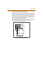
Installing the Serial Interface Unit (SIU)
1. Unpack the SIU from its antistatic conductive bag in the packing box.
There should also be a plastic bag with two plastic standoffs and two
metal screws.
2. Push the two standoffs into the holes on the SIU board. (Refer to
Figure 2-14.)
3. Locate the CONN1 connector and the two screw holes (outlined) on
the MISU.
4. Push the SIU board onto the CONN1 connector and be sure it is
seated correctly.
5. From the back side of the MISU board, insert the two metal screws
into the holes and tighten them into the bottom of each standoff to
secure.
This completes the installation procedure for the SIU.
2-32
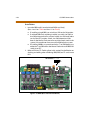
Miscellaneous Interface Unit (MISU) Installation
CONN3
CONN1
SIU
CONN
CONN2
SIU
RS232C
TERMINAL
9 PIN
9 PIN
2 (T X)
2 (RX)
3 (RX)
5 (GND)
3 ( TX)
5 (GND)
2 (T X)
3 (RX)
3 (RX)
5 (GND)
2 ( TX)
5 (GND)
9 PIN
25 PIN
Figure 2-14: MISU w/SIU Installation
CO/PBX Connections
2-33
CO/PBX Connections
There are two types of analog CO/PBX Line interface boards available.
These boards include the Loop Start CO Line Interface Board (LCOB),
Direct In-Dial Interface Board (DIDB).
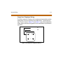
Loop Start CO Interface Board (LCOB)
The Loop Start CO Interface Board supports up to six (6) Loop Start
Central Office Lines and can be optionally equipped with a DTMF Receive
Unit (DTRU) daughter board to detect DTMF for Single Line devices.
Installing the DTRU Module
1. Unpack the DTRU Module from its antistatic conductive bag in the
packing box.
2. Locate the CON1 and CON2 connectors on the DTRU module.
3. Locate the CN1 and CN2 connectors on the LCOB (outlined).
4. Position the DTRU module so that the CON2 and CON1 connectors
match up with the CN1 and CN2 connectors on the LCOB
respectively.
5. Push the DTRU module onto these connectors making sure it is
seated properly.
Refer to Figure 2-15. This completes the installation procedure for the
DTRU Module.
2-34
CO/PBX Connections
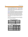
Table 2-3: LCOB Wiring
LCOB Connector
Connector
Pin #
LCOB
Designation
J2
3
Tip 1
2
Ring 1
4
Tip 2
1
Ring 2
3
Tip 3
2
Ring 3
4
Tip 4
1
Ring 4
3
Tip 5
2
Ring 5
4
Tip 6
1
Ring 6
J3
J4
CO/PBX Connections
2-35
CON2
DTRU
CON1
Figure 2-15: LCOB w/DTRU Installation
2-36
CO/PBX Connections
DID Interface Board (DIDB)
The Direct In-Dial Interface board (DIDB) provides four (4) analog DID CO
interface ports. The DIDB can be optionally equipped with a DTMF
Receiver Unit (DTRU) daughter board to detect DTMF tones.
Installing the DTRU Module
1. Unpack the DTRU Module from its antistatic conductive bag in the
packing box.
2. Locate the CON1 and CON2 connectors on the DTRU module.
3. Locate the CN1 and CN2 connectors on the LCOB (outlined).
4. Position the DTRU module so that the CON2 and CON1 connectors
match up with the CN1 and CN2 connectors on the LCOB
respectively.
5. Push the DTRU module onto these connectors making sure it is
seated properly.
Refer to Figure 2-16. This completes the installation procedure for the
DTRU Module.
CO/PBX Connections
2-37
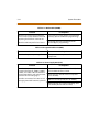
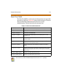
Table 2-4: DIDB Wiring
Connections
Designation
Connector
Pin #
J3
3
Tip 1
2
Ring 1
1
Tip 2
4
Ring 2
3
Tip 3
2
Ring 3
1
Tip 4
4
Ring 4
J4
2-38
CO/PBX Connections
CON2
CN1
DTRU
CN2
CON1
Figure 2-16: DIDB w/DTRU Installation
CO/PBX Connections
2-39
T-1 Interface Board (T1IB)
The T1IB provides the T-1 (1.544Mbps, 24-Voice Channel) digital interface
circuit, control circuitry, and synchronous clock control circuits. DTMF
tone detection units can be installed optionally on the T1IB. The T1IB has
8 LEDs on the front edge of the PCB which indicates errors of T-1 line,
in-use status, and synchronous clock enable status.
The PLLU must be installed on the MPB for the T-1 card to operate
properly.
Software 2.1G or newer is needed when using any T-1 card that contains
1.0G Firmware. Withoutthe newer software, the T-1 card will not work.
Table 2-5: T-1 Board LEDS
LED #
Function
1
IN USE. At least one of the 24 circuits is in use.
2
RED. T1IB is in REd alarm due to any alarm.
3
H/W TEST. Normal call processing is not available.
4
BLUE. T1IB has detected RX_BLUE alarm.
5
YELLOW: T1IB has detected RX_YELLOW alarm.
6
OOF. T1IB is Out of Frame synchronization.
7
RCL. T1IB receives Carrier Loss (unplugged from the
cable)
8
CLOCK. Clock Enable/Disable
The T1IB contains 2 switches (SW1 and SW3) and 3 connectors (CON1,
CON2 and CON3). The clock selection switch is used for control
synchronous clock. The Line Build-Out switch is controlled by distance
between the Triad 1/2 Systems and a CSU and SW1 #4 is used for
loopback control.
2-40
CO/PBX Connections
The system can be equipped with two (2) T-1 Interface Boards and the
T1IB can be installed in Slots 0 thru 2 in the Triad 1 Basic KSU, while the
T1IB can be installed in Slots 0 thru 5 in the Triad 2 Basic KSU. The Phase
Locked Loop Unit (PLLU) must be installed on the MPB when the T1IB is
installed. The DTMF4-A board which contains 4 DTMF receivers can be
optionally installed on the T1IB.
The clock control cable should be connected by daisy-chain method like
Figure 2-18 when more than one T1IB boards are installed. When the
clock control cable of the T1IB is connected by daisy-chain method, the
clock selection switch of the first T1IB must be placed in the Enable
position and the other board should be placed in the Disable position.
The Line Build-Out switch must be selected by distance between the
Triad 1/2 Systems and a CSU and the switch selection as indicated in the
following chart. If the CSU is located near the KSU, all LBO switches
should be ON.
The SW1 switch #4 of the Line Build-Out switch is used for LoopBack
control. Its switch is used only for hardware test and must be placed in
the ON position for normal operation.
Table 2-6: T-1 Ordering Information
T-1 Ordering Information
Ringer Equivalent Number:
6.0P
Facility Line Interface:
04DU9-B
Jack Type:
RJ48C
Table 2-7: T-1 Switch Positions
Distance
Switch #
1
2
3
4
0 to 133 feet
on
on
on
on
133 to 266 feet
off
on
on
on
266 to 399 feet
on
off
on
on
399 to 533 feet
off
off
on
on
533 to 655 feet
on
on
off
on
CO/PBX Connections
2-41
This board supports standard D4 framing format with robbed bit
signaling. Extended Super Frame (ESF) format is also supported.
The board requires an external CSU unit.
The T-1 board can accept two (2) DTMF4-A units in a daughter board
type arrangement. Each unit has 4 DTMF Receivers installed on it.
This board can be installed on the SLIB, and T1IB boards.
The board has a 15-pin D Sub connector for connection to a CSU unit.
The card ejector tabs are color coded white.
Functionality Description
Automatic Number Identification (ANI) information from the
carrier is treated exactly the same as an inbound ICLID (Caller ID)
number. Calls can be routed, placed in the Unanswered Call Table,
sent out to the CTI Module port on a keyset, and run through the
Number To Name Translation Table. The Triad 2 system provides call
progress tones in the same manner as ICLID.
Dialed Number Identification Service (DNIS) information from the
carrier is treated using DID line rules. DNIS calls are routed based on
the DID Routing Table.
ANI/DNIS is a combined format, where the system waits for the ANI/
DNIS information from the carrier. When it is received, the system
routes the call using ICLID processing. If this information is not found
in the ICLID Route Tables, the DNIS information is compared to the
DID table for a match. The call is then routed based on the DID tables.
If a match is not found on either the ANI or DNIS number, the call is
routed based on normal CO line operation (CO Ringing Assignments).
2-42
CO/PBX Connections
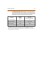
The following table summarizes the operation of the system.
Table 2-8: Call Routing Criteria
ANI
DNIS
Operation
N
N
Calls routed based on normal CO operation (CO Ring Assignments.
N
Y
Calls routed based on DID tables with DID operation.
Y
N
Calls routed based on ICLID routing and ICLID operation.
Y*
Y
Calls routed on ICLID first, if no route is found, the DNIS digits are
compared to the DID table. If no route is found in the DID table the
call is routed based on CO line Ringing Assignments.
*I f both ANI and DNIS calls are routed -- the following tabl e summarizes what i s displayed at the phone.
The T-1 card accepts ANI/DNIS information in a DTMF format only. Some carriers do not
provide ANI or ANI/DNIS in a DTMF format.Consult your local carrier for available
options.
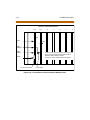
Table 2-9: Call Routing Display Format
Route
Found
Type of
Display
ICLID
ICLID
ANI number placed in the 14-character number field,
the DNIS number followed by the name programmed
in ICLID translation table placed in the 24-character
name field.
DID
ICLID
ANI number placed in 14-character number field. DNIS
number followed by programmed name from the DID
tables in 24-character name field.
NONE
ICLID
ANI number placed in 14-character number field and
the DNIS number is placed in the 24-character name
field.
Format
CO/PBX Connections
2-43
T-1 Ordering Information: When ordering a T-1 circuit from a carrier,
request either D4 framing and Alternate Mark Inversion (AMI) Line coding
using the superframe (SF) or the Extended Superframe (ESF-B8ZS) format.
The following are additional ordering information specifications:
Table 2-10: T-1 Ordering Specifications
If ordering…
ANI/DNIS/
DID/TIE
Loop Start/
Ground Start Signaling*
Circuit Information
2 wire
2 wire
TIE
Loop or Ground
Address Signaling
DTMF
DTMF
Start Dial Indicator
Wink Start
Dial Tone
Supervisory Signaling
* ANI/DNIS not avai lable on Loop/Ground start si gnaling. If Loop Start signaling protocol is ordered, the
Ce ntral O ffice doe s not provide Disconne ct Supervision. However i f TIE signaling protocol is ordered,
disconnect supervision is provided. The swi tching equipment processes DNIS numbers re ceived from the
T-1 ci rcuit dependi ng on the trunk simul ation.
2-44
CO/PBX Connections
MULTIPLE CARD ARRANGEMENT
1
T1-2
T1-3
4
5
6
7
8
UP
SW-3
DN
CTRL
CLKOUT
CTRL
CLK IN
In the case of a Master system, the clock
cable does not get connected and SW3 on
all T-1 Boards is in the down position. Two
(2) T-1 Cards maximum in the system.
CON3
T-1 Lines from Telco
Clock Cable
Figure 2-17: T-1 Clock Connect Cable Installation (Multiple Cards)
CO/PBX Connections
2-45
SINGLE CARD ARRANGEMENT
1
T1-2
T1-3
4
5
6
7
UP
SW-3
CON3
T-1 Lines from Telco
Figure 2-18: T-1 Clock Connect Cable Installation (Single Card)
8
2-46
CO/PBX Connections
Installing the DTMF-A Modules
1. Unpack the DTMF-A Modules from their antistatic conductive bags in
the packing boxes.
2. Locate the CONN5 and CONN6 connectors on the DTMF-A modules.
3. Locate the CON4, CON5, CON8 and CON9 connectors on the T1IB
(outlined).
4. Position one of the DTMF-A modules so that the CONN5 and CONN6
connectors match up with the CON8 and CON9 connectors on the
T1IB respectively.
5. Push the DTMF-A module onto these connectors making sure it is
seated properly.
6. Position the second DTMF-A module so that the CONN5 and CONN6
connectors match up with the CON4 and CON5 connectors on the
T1IB respectively.
7. Push the DTMF-A module onto these connectors making sure it is
seated properly.
Refer to Figure 2-19. This completes the installation procedure for the
DTMF-A Modules.
CO/PBX Connections
2-47
-A
MF
DT
DTM
CONN6
CON9
CON8
F- A
CONN6
CON5
CON4
Figure 2-19: T1IB w/DTMF4_A Module Installation
2-48
CO/PBX Connections
Primary Rate Interface Board (PRIB)
This interface provides one Primary Rate Interface circuit. Each circuit
contains 23 bearer and one data channel (23B+D). When a PRIB card is
programmed into the Triad 1/2 system, the system interprets all
B channels as trunks. Thus, one PRIB which contains 23B+D circuits
provides 23 line appearances to the Triad 1/2 system. A maximum of two
PRIB boards may be installed into the system. The PRIB card uses 24 time
slots when installed.
The PRIB must be used in conjunction with a Channel Service Unit (CSU).
Connection is made via a DB15 from the PRIB to the CSU.
The PRIB accepts two DTMF-A boards.
When ordering PRI lines from the telephone company, specify ESF
framing and B8ZS line coding. PRI only supports National ISDN 2 (NI-2).
No other standards are supported.
Vodavi has successfully integrated its PRI ISDN with the Lucent 5 ESS,
Siemens, Stromburg Carlson, and the DMS100 Central Offices. Vodavi
ISDN should work with all Central Office switches, but this has not been
verified. Therefore, some delays in service may be experienced.
Installation
1. Insert the PRIB card(s) into the desired BKSU card slot(s). Up to two
PRIB cards can be installed in a system (Slots 1 and 2 on Triad 1 and
slots 1-5 on Triad 2).
2. If installing a single PRIB, set SW2 to the ON position.
If multiple PRIBs are being installed, set SW2 to the ON position on
the first card and SW2 on all other cards to the OFF position.
The PRIB comes with a clock cable. This cable is used when multiple
PRIB and/or digital trunk cards are to be installed in the system. The
clock cable is supplied with each PRIB.
3. Connect the DB15 cable from the PRIB to the channel service unit
(CSU).
4. Connect the network cable from the channel service unit to the
network.
5. Refer to ISDN and T1 Clocking (later in this section) for clarification on
clocking and cabling when combining BRIB, PRIB, and T1 cards in one
KSU.
CO/PBX Connections
2-49
Figure 2-20: PRIB (Primary Rate Interface Board)
The PRIB is offered as a stand-alone card or as a kit which includes the
PRIB, CSU, and cables.
Basic Rate Interface Board (BRIB)
This interface provides four Basic Rate Interface circuits. Each circuit is
comprised of two bearer (64Kbps each) and one data (16Kbps) channels
(2B+D). When a BRIB is programmed into the Triad 1/2 system, the system
interprets all B channels as trunks. Thus, one BRIB which contains four
2B+D circuits provides eight line appearances to the Triad 1/2 system. A
maximum of five BRIBs can be installed into the system (40 B channels).
The BRIB uses the U interface of the BRI standard. Connection to the
network is made via RJ45 connectors on the front edge of the board. No
NT1 device is required to connect to the central office. The BRIB card uses
eight time slots when installed.
When ordering BRI lines from the telephone company, specify
Capability P as the ordering code. National ISDN 1 (NI-1) is supported. No
other standards are supported.
Vodavi has successfully integrated its BRI ISDN with the Lucent 5 ESS
CentralOffice.Vodavi ISDN should work withall CentralOffice switches,
but this has not been verified. Therefore, some delays in service may be
experienced.
2-50
CO/PBX Connections
Installation
1. Insert the BRIB card(s) into the desired BKSU card slot(s).
(Slots 1 and 2 on Triad 1 and slots 1-5 on Triad 2)
If installing a single BRIB, set switch 4 on SW2 to the ON position.
If multiple BRIB cards are being installed, set switch 4 on SW2 to
the ON position on the first card and switch 4 on SW2 on all other
cards to the OFF position. Switch 4 on SW2 determines if the
board is the Master Clock source for any digital trunk cards in the
system. Only one Master Source must be enabled in the system.
If installing a BRIB in a system that also has T1 or PRIB boards, use
either the T1 or PRIB card as the Master Clock and set all BRIB SW2
switch 4s to OFF.
2. Refer to ISDN and T1 Clocking (later in this section) for clarification on
clocking and cabling when combining BRIB, PRIB, and T1 cards in one
KSU.
SW2 SWITCHES: 1 2 3 4
ON
OFF
Figure 2-21: BRIB (Basis Rate Interface Board)
CO/PBX Connections
2-51
Electronic Key Telephone Service
Electronic key telephone service (EKTS) is a feature that can be provided
on BRI ISDN to simulate standard analog DID lines. This allows several
different numbers to be shared by a single BRI circuit.
Due to the decline in telephony tariffs, there is an increasing demand for
BRI ISDN features. A BRI circuit allows two simultaneous calls to be
handled, due to its technical specification. BRI circuits have two
B-Channels at 64 kilobytes per second and one D-Channel at 16 kilobytes
per second. The Bearer (B) Channels are designed for PCM (voice) and the
Data (D) Channel is designed to carry information specific to each
incoming and/or outgoing call.
The EKTS feature allows a single ISDN Service Profile Identifier (SPID) or
B-Channel to support multiple directory numbers. A SPID is a number
that telephone company switching equipment uses to track
configuration information for each terminal adapter connected to an
ISDN telephone line. The telephone company should provide SPIDs at
the same time that the ISDN directory numbers are assigned. A directory
number is another term for a telephone number.
If an application requires EKTS, be aware that BRI ISDN handles a busy
number differently than a DID circuit. When the called number is busy,
BRI will issue a busy signal, but a DID circuit will ring another line in the
circuit. The busy signal is provided by the telephone company, therefore
the call is not presented to the Vodavi telephone switch and it is not
forwarded to voice mail. For example, a caller dials 480-443-6000 and is
connected to the extension. While the first caller is still connected, a
second caller dials the same number. The second caller will receive a busy
signal that is provided by the telephone company.
In a normal BRI application, two numbers are assigned to each BRI circuit,
which consists of 2 channels. There can be a maximum of 4 circuits
equipped to handle 8 channels per BRIB. This is a direct number-tochannel relationship without hunting capability. Most circuit providers
offer an optional “hunting” feature capability on BRI circuits. This optional
feature allows numbers to hunt for idle channels on the BRIB up to a
maximum of 8 channels per BRIB, assuming four BRI circuits were
installed. In EKTS applications, you can have a maximum of 64 DID
numbers hunt to one BRIB. Hunting cannot be accomplished between
BRIBs, nor will the hunting feature allow calls to be routed to a busy DID
number.
2-52
CO/PBX Connections
Conditions
BRI EKTS support is available in Vodavi telephone systems with software
version 3.0G and higher.
Like DID, EKTS can be programmed to route calls using up to 7 digits. By
default, only the last three digits are analyzed for routing.
EKTS does not require a line appearance on a specific telephone because
the BRI terminates directly into the KSU.
Vodavi supports Basic EKTS. The EKTS caching option is not supported by
Vodavi. Caching is normally used when an ISDN telephone instrument is
used on the customer premise.
ISDN and T1 Clocking
When combining BRIB, PRIB, and T1 cards in one KSU, specific settings
and cabling are important for proper clocking. The Phase Lock Loop Unit
(PLLU) synchronizes the clocking from the Central Office to the clocking
of the KSU. Popping, crackling, dropped calls, and one-way transmission
are usually attributed to the clocking not being synchronized correctly.
Examples - Settings and Cabling
The following examples clarify the clocking and cabling for these cards:
When the switch is in the “up” position, it should be considered “ON”.
When the switch is in the “down” position, it should be considered “OFF”.
The cable connection follows the same logic - “up” is clock outside (ON)
and “down” is clock inside (OFF). ON means thatclockingis comingfrom
outside the KSU and OFF means that clocking is coming from inside the
KSU.
CO/PBX Connections
2-53
(1) T1IB and (1)PRIB
T1IB
PRIB
SW3 On
SW2 Off
If both cards in a phone switch are connected to a telephone company
clock (not point-to-point T1), put the T1 clock switch in the enable
position (UP) to allow it to receive clocking from the telephone company
directly, and do not install the clock cable. Set the PRIB clock switch in the
disable position (OFF), which allows the PRIB to synchronize its timing off
of the backplane (from the T1 clocking). If the T1 is a point-to-point T1,
set the PRIB in the enable position (ON), the T1 in the disable position
(OFF), and do not install the clock cable.
(1) PRIB and (1) BRIB
PRIB
Sw2 On
BRIB
Switch 4, SW2 On
Install with the cable and set both PRIB and BRIB switches to the enable
position (ON).
2-54
CO/PBX Connections
(1) T1IB and (1) BRIB
T1IB
BRIB
SW3 On
Switch 4, SW2 Off
If both cards in a phone switch are connected to a telephone company
clock (not point-to-point T1), put the T1 clock switch in the enable
position (ON) to allow it to receive clocking from the telephone company
directly. Do not install the clock cable. Set the BRIB clock switch in the
disable position (OFF), which allows the BRIB to synchronize its timing off
of the backplane (from the T1 clocking). If the T1 is a point-to-point T1,
set the BRIB to the enable position (ON), the T1 in the disable position
(OFF), and do not install the clock table.
(2) PRIBs and (3) T1IBs
PRIB1
PRIB2
T1IB1
T1IB2
T1IB3
SW2 On
SW2 On
SW3 Off
SW3 Off
SW3 Off
The clock cable should be connected to the OUT position on the
connector on the PRIB1. The clock cable should be connected to the IN
position on PRIB2. SW2 of the PRIB1 and PRIB2 should be placed in the
CO/PBX Connections
2-55
ON position. The three T1IBs are not connected with the clock control
cable and SW3 on these boards should be in the OFF position.
(3) T1IBs and (2) PRIBs
T1IB1
T1IB2
T1IB3
PRIB1
PRIB2
SW3 On
SW3 Off
SW3 Off
SW2 Off
SW2 Off
The clock cable should be connected to the OUT position on the cable
connector on the T1IB and connected to the IN position on the connector
on the T1IB2. The clock cable should be connected to the OUT position
on T1IB2 and connected to the IN position on the T1IB3. SW3 of T1IB1
should be placed in the ON position, with SW3 on T1IB2 and T1IB3 being
OFF. The two PRIBs are not connected with clock control cables, and SW2
on the PRIBs should be in the OFF position.
(3) PRIBs and (2) BRIBs
PRIB1
SW2 On
PRIB2
SW2 On
PRIB3
BRIB1
BRIB2
SW2 On Switch 4, SW2 On Switch 4, SW2 On
The clock cable should be connected from the OUT position of the PRIB1
to the IN connectors of all the cards and all clock switches should be in
the ON position.
2-56
CO/PBX Connections
(3) T1IBs and (2) BRIBs
T1IB1
SW3 On
T1IB2
T1IB3
BRIB1
BRIB2
SW3 Off
SW3 Off Switch 4, SW2 Off Switch 4, SW2 Off
The clock OUT cable from T1IB1 should be connected to the clock IN
cable of the T1IB2 and the clock OUT cable from T1IB2 should be
connected to the clock IN cable of T1IB3. SW3 of T1IB1 should be in the
ON position, and SW3 of T1IB2 and T1IB3 should be in the OFF position.
The two BRIBs are not connected with clock control cables and SW2 of
the BRIB cards are placed in the OFF position.
Station Connections
2-57
Station Connections
The system can be equipped with any combination of the four station
boards; DTIB12, DTIB24, ETIB and SLIB6. The station interface boards can
be installed in any card slot in the BKSU and EKSU, except for MPB slot of
the BKSU. As a default, the software allocates slots 1 through 5 of the
BKSU and 9 through 10 of the EKSU for station interface boards. It is
recommended that slots beginning from SLOT #1 be used for station
interface boards. Also, since the first port of the DTIB is the database
access port (the only port which enables Admin programming), it is
strongly recommended that a DTIB be installed in the SLOT #1 and a
Digital Keyset w/LCD be connected to the first port.
Electronic Telephone Interface Board (ETIB)
The ETIB board provides the interface to twelve (12) electronic
telephones or DSS/DTS terminals. The card has one LED indicator for
off-hook/in use status. The ETIB card extractors are color coded green.
There is one 50-pin female amphenol connectors labeled Conn2 located
on the front of the card. This allows the system to be cabled to the main
distribution frame (MDF). 25-pair telephone cabling must be prepared
with mating connectors to extend the interface circuits to the MDF. The
cables should be routed through the cable clamps at the bottom of the
KSU to the MDF. These cables are then terminated on industry standard
66M1-50 type punchdown connector blocks. It is recommended that
66M1-50 split blocks with bridging clips be used to simplify
troubleshooting and to quickly isolate faults.
Only DTIB type stations can be used for Database programming.
2-58
Station Connections
Table 2-11: ETIB Wiring
Pair
PIN #
Color
Description
1
26
1
WH/BL
BL/WH
VT-1
VR-1
2
27
2
WH/OR
OR/WH
DT-1
DR-1
3
28
3
WH/GN
GN/WH
VT-2
VR-2
4
29
4
WH/BN
BN/WH
DT-2
DR-2
5
30
5
WH/SL
SL/WH
VT-3
VR-3
6
31
6
RD/BL
BL/RD
DT-3
DR-3
7
32
7
RD/OR
OR/RD
VT-4
VR-4
8
33
8
RD/GN
GN/RD
DT-4
DR-4
9
34
9
RD/BN
BN/RD
VT-5
VR-5
10
35
10
RD/SL
SL/RD
DT-5
DR-5
11
36
11
BK/BL
BL/BK
VT-6
VR-6
12
37
12
BK/OR
OR/BK
DT-6
DR-6
CKT1
CKT2
CKT3
CKT4
CKT5
CKT6
Pair
PIN #
Color
Description
13
38
13
BK/GN
GN/BK
VT-7
VR-7
14
39
14
BK/BN
BN/BK
DT-7
DR-7
15
40
15
BK/SL
SL/BK
VT-8
VR-8
16
41
16
YL/BL
BL/YL
DT-8
DR-8
17
42
17
YL/OR
OR/YL
VT-9
VR-9
18
43
18
YL/GN
GN/YL
DT-9
DR-9
19
44
19
YL/BN
BN/YL
VT-10
VR-10
20
45
20
YL/SL
SL/YL
DT-10
DR-10
21
46
21
VI/BL
BL/VI
VT-11
VR-11
22
47
22
VI/OR
OR/VI
DT-11
DR-11
23
48
23
VI/GN
GN/VI
VT-12
VR-12
24
49
24
VI/BN
BN/VI
DT-12
DR-12
25
50
25
VI/SL
SL/VI
CKT7
CKT8
CKT9
CKT10
CKT11
CKT12
Station Connections
Figure 2-22: Electronic Telephone Interface Board (ETIB)
2-59
2-60
Station Connections
Single Line Interface Board (SLIB)
This board provides the interface to six (6) 2500 type telephones. The
SLIB signals interface with mechanical 90V ringers and lights 90V
message waiting lamps on 2500 sets as desired.
Only one SLT station is allowed per digital extension number. It is not
possible to bridge digital station ports so that an extension number may
appear in more than one location.
The station connections are via three (3) Modular (RJ14 type) connectors
located on the front edge of the card. The board can support a DTRU
board and a MSG12 board in a daughter board type arrangement.
The DTRU unit has two (2) DTMF receivers on it and can be installed on
the SLIB board. The DTRU mounts on the SLIB board as a daughter board
type arrangement.
Table 2-12: SLIB Wiring
SLIB Connector
Connector
Pin #
3M Connection
6M Connection
M3
3
Tip 6
Tip 6
2
Ring 6
Ring 6
4
Tip 5
Tip 5
1
Ring 5
Ring 5
3
Tip 4
Tip 4
2
Ring 4
Ring 4
4
Tip 3
Tip 3
1
Ring 3
Ring 3
3
Tip 2
Tip 2
2
Ring 2
Ring 2
4
Tip 1
Tip 1
1
Ring 1
Ring 1
M2
M1
Station Connections
2-61
Installing the DTRU Module
1. Unpack the DTRU Module from its antistatic conductive bag in the
packing box.
2. Locate the CON1 and CON2 connectors on the DTRU module.
3. Locate the CONN1 and CONN2 connectors on the SLIB (outlined).
4. Position the DTRU module so that the CON2 and CON1 connectors
match up with the CONN1 and CONN2 connectors on the SLIB
respectively.
5. Push the DTRU module onto these connectors making sure it is
seated properly.
Refer to Figure 2-23. This completes the installation procedure for the
DTRU Module.
Installing the MSGU Board
The Message Wait Lamp Relay Control (MSGU) provides Message Wait
Lamp Relay Control for message lamp single line telephones. The MSGU
board mounts on the SLIB board as a daughter board type arrangement.
1. Unpack the MSGU Module from its antistatic conductive bag in the
packing box.
2. Locate the CONN1 and CONN2 connectors on the MSGU module.
3. Locate the CONN3, and CONN4 connectors on the SLIB (outlined).
4. Position the MSGU module so that the CONN1 and CONN2
connectors match up with the CONN3 and CONN4 connectors on the
SLIB respectively.
5. Push the MSGU module onto these connectors making sure it is
seated properly.
Refer to Figure 2-23. This completes the installation procedure for the
MSGU Module.
2-62
Station Connections
Adjusting Modem Settings
When using modems connected to SLT ports on the Triad 1/2/3, the gain
settings on the SLT port when using T1 as access to the CO should be set
to 0 dB (maximizes modem speed).
CO to SLT Call via a T1 TIE Trunk:
1. Access the specific trunk type above.
2. Hookflash and dial 638 8 on the keypad.
3. Hang up.
CO to SLT Call via a T1 Trunk:
1. Access the specific trunk type above.
2. Hookflash and dial 638 6 on the keypad.
3. Hang up.
SLT to SLT Call:
1. Place an intercom call from 1 SLT to another.
2. Hookflash and dial 638 5 on the keypad.
3. Hang up.
No adjustment is needed if access to the CO is accomplished by standard
loop/ground start trunk circuits. These trunk types are set to 0 dB by
default.
In all cases the maximum modem speed is not as much as if the modem
were connected directly to the CO line. The system degrades the
connection to the next lower baud rate that the modem supports.
Example: If the modem can achieve 28800 on a direct CO line, the
maximum speed on an SLT port would be 26400.
Testing proves that a baud rate of 33600 can be achieved with SLT-T1
lines. Typical connection speeds with SLT-T1 are 22700-33600. Typical
connection speeds with SLT-Loop/Ground Start are 17400-23800.
All results were obtained using a 56K U.S. Robotics Sportster modem.
Station Connections
2-63
CONN1
CON2
DTRU
CONN2
CONN3
CONN4
CON1
MSGU
CONN1
Figure 2-23: SLIB w/MSGU and DTRU Module Installation
2-64
Station Connections
Digital Telephone Interface Board (DTIB)
The DTIB board provides the interface to twelve (12) digital telephones. It
is offered in two (2) versions, a 12-circuit and a 24-circuit. The card has
one LED to indicate off-hook/in use status. The DTIB card extractors are
color coded green.
Only one stationisallowedperdigitalextension number.Itis notpossible
to bridge digital station ports so that an extension number may appear
in more than one location.
Cables
There is one 50-pin female amphenol connectors labeled Conn2 located
on the front of the card. This allows the system to be cabled to the main
distribution frame (MDF).
25-pair telephone cabling must be prepared with mating connectors
to extend the interface circuits to the MDF.
Cables should be routed through the cable clamps at the bottom of
the KSU to the MDF. These cables are then terminated on industry
standard 66M1-50 type punchdown connector blocks.
It is recommended that 66M1-50 split blocks with bridging clips be
used to simplify troubleshooting and to quickly isolate faults.
Station Connections
2-65
Table 2-13: DTIB Wiring
Color
Description
Pair
PIN #
Color
Description
26
1
WH/BL
BL/WH
DATA-R 1
DATA-T 1
13
38
13
BK/GN
GN/BK
DATA-R 13
DATA-T 13
2
27
2
WH/OR
OR/WH
DATA-R 2
DATA-T 2
14
39
14
BK/BN
BN/BK
DATA-R 14
DATA-T 14
3
28
3
WH/GN
GN/WH
DATA-R 3
DATA-T 3
15
40
15
BK/SL
SL/BK
DATA-R 15
DATA-T 15
4
29
4
WH/BN
BN/WH
DATA-R 4
DATA-T 4
16
41
16
YL/BL
BL/YL
DATA-R 16
DATA-T 16
5
30
5
WH/SL
SL/WH
DATA-R 5
DATA-T 5
17
42
17
YL/OR
OR/YL
DATA-R 17
DATA-T 17
6
31
6
RD/BL
BL/RD
DATA-R 6
DATA-T 6
18
43
18
YL/GN
GN/YL
DATA-R 18
DATA-T 18
7
32
7
RD/OR
OR/RD
DATA-R 7
DATA-T 7
19
44
19
YL/BN
BN/YL
DATA-R 19
DATA-T 19
8
33
8
RD/GN
GN/RD
DATA-R 8
DATA-T 8
20
45
20
YL/SL
SL/YL
DATA-R 20
DATA-T 20
9
34
9
RD/BN
BN/RD
DATA-R 9
DATA-T 9
21
46
21
VI/BL
BL/VI
DATA-R 21
DATA-T 21
10
35
10
RD/SL
SL/RD
DATA-R 10
DATA-T 10
22
47
22
VI/OR
OR/VI
DATA-R 22
DATA-T 22
11
36
11
BK/BL
BL/BK
DATA-R 11
DATA-T 11
23
48
23
VI/GN
GN/VI
DATA-R 23
DATA-T 23
12
37
12
BK/OR
OR/BK
DATA-R 12
DATA-T 12
24
49
24
VI/BN
BN/VI
DATA-R 24
DATA-T 24
25
50
25
VI/SL
SL/VI
DTIB12 Station Ports
1
DTIB24 Station Ports
Pair PIN #
2-66
Station Connections
Figure 2-24: Digital Telephone Interface Board (DTIB) Installation
System Wiring
2-67
System Wiring
Battery Back-Up Wiring Installation
The system can be equipped to provide operation from external batteries
if local AC power fails. The Back-Up batteries are connected to the strip
connector on the front of the PSU as shown:
PSU
- +
+
-
+MARKER
-MARKER
BATT
+
-
4 PIN
CONN
Figure 2-25: Battery Back-Up Wiring
The external batteries must provide 24 Volts DC. This is generally
accomplished by connecting two 12 volt batteries in a series
arrangement. Operation on batteries is controlled by the PSU. This PSU
provides charging current to the batteries during normal AC power
operation at a maximum of about 1 amp.
During battery operation, the PSUs discontinue battery operation if the
AC power is reapplied or the battery voltage is too low to maintain
proper system operation. If a low-battery cut-off occurs and a new
battery is installed, it is necessary to reset the Battery Back-Up circuit in
the PSU manually by momentarily depressing the white colored BATT.
RESTART switch located on the faceplate of the PSU.
2-68
System Wiring
The length of time the system operates on the batteries is dependent on
several elements including: battery charge state, condition of the
batteries, capacity of the batteries, and the size of the system (number of
station ports).
The following chart gives the approximate back-up time for several
system sizes and different battery capacities in ampere-hours.
Table 2-14: System Back-Up Duration
Battery Capacity
36 Ports
60 Ports
20AH
4 Hour
1.75 Hour
40AH
8 Hour
3.5 Hour
MPB and SIU RS232C Port Wiring
The MPB has one standard RS232C port and the SIU has two standard
RS232C ports. The RS232C ports are connected by 9-pin D connectors as
shown in Figure2-26. Note the configuration is 8 bits, no parity and 1 stop
bit.
MPB & SIU
RS232C
TERMINAL
9 PIN
9 PIN
2 ( TX)
2 (RX)
3 (RX)
3 ( TX)
5 (GND)
5 (GND)
2 ( TX)
3 (RX)
3 (RX)
2 ( TX)
5 (GND)
5 (GND)
9 PIN
25 PIN
Figure 2-26: RS232 9-Pin Connector Wiring
System Wiring
2-69
MISU Wiring
The MISB has connections for 2 music sources, 2 External page zones and
4 relay contact controls. The MISB connections are made by the 25 pair
connector. The wiring connections for the 25-pair cable are identified in
Table 2-2.
Station Wiring
Station interface boards (DTIB, ETIB, SLIB) includes a 25 pair connector for
station wiring to the ports on the board. The following provides details
on the interconnection of each type of station interface board and the
station jack.
Digital Keyset and Terminal Wiring
Wiring from the DTIB to station jack requires one pair of wire. Digitized
voice, signaling, and power are sent over this pair.
Figure 2-27 gives details on connections of station jacks to the system and
Table 2-13 gives the configuration of the 25-pair station connector
arrangement and punchdown type block.
DT (GREEN)
DR (RED)
G
R
Y
BK
Figure 2-27: Digital Station Jack Wiring
Only the first pair (Red, Green on jack) should be connected back to the
KSU. No other pairs should be connected back to the KSU.
2-70
System Wiring
Electronic Keyset and Terminal Wiring
Wiring from the ETIB to station jack requires two pairs of wire. The first
pair provides the audio or voice path, the second is for signaling or data
path. The DATA pair is polarity sensitive, reversal does not harm the
keyset or system, but the port does not function properly when reversed.
Power is delivered by applying DC voltage to the center tap of the
coupling transformers of each of the 2 pairs.
Figure 2-22 gives details on connections of station jacks to the system and
Table 2-11gives the configuration of the 25-pair station connector
arrangement and punchdown type block.
VT (GREEN)
VR (RED)
DT (BLACK)
DR ( YELLOW)
G
R
Y
BK
Figure 2-28: Electronic Station Wiring
System Wiring
2-71
Single Line Telephone Wiring
The SLIB is wired to SLT devices with a single pair of wire which provides
battery feed, voice and signaling to and from the SLT. Typical wiring to
the SLT jack is shown in Figure 2-29 and Table 2-12gives the configuration
of the station connector arrangement when connected to a punchdown
type block.
VT
VR
G
Y
R
B
Figure 2-29: Single Line Telephone Wiring
2-72
System Wiring
Power Failure Transfer Wiring
The PFTU is wired from the 25-pair connector to the MDF, cross
connected to the CO Line inputs from the telephone company, to the CO
Line inputs of the system, and to Power Failure SLTs. The basic
connections are shown in Figure 2-30 and the connector configuration is
given in Table 2-12. Note that the SLT may also be connected to a SLIB as
shown in the figure.
MDF (PFTU)
CO L1
CO L2
1
26
COR1-IN
COT1-IN
2
27
COR1-OUT
COT1-OUT
SLT
3
28
TEL1-R
TEL1-T
SLIB24
Subscriber
4
29
SLIB1-R
SLIB1-T
LCOB
Figure 2-30: PFTU Wiring
Wall Mounting the Electronic Telephone
2-73
Wall Mounting the Electronic Telephone
All connections to the Electronic Key Telephone are fully modular. To wall
mount the Electronic Key Telephone, it is necessary to have one Wall
Mount Kit and one standard-type jack assembly designed for normal wall
hanging applications.
1. Unplug the line cord from the phone. This line cord is not be required
and should be retained as a maintenance replacement item.
2. Lift the plastic number retainer upward and expose the screw
underneath. Remove the screw and the handset tab. Replace it with
the handset tab from the Wall Mount Kit.
3. Be careful to position the tab so that the protrusion faces the
hookswitch. This allows the handset to remain secure when the
telephone is on the wall. Replace the screw and snap the number
retainer into place.
4. Substitute the short modular cord from the Wall Mount Assembly
into the modular connector vacated by the line cord.
5. Align the wall mount baseplate with holes on the bottom of the
telephone. Snap in place.
6. Now match the two key hole slots on the baseplate with the lugs on
the 630-A type jack. Align the modular connector and slide telephone
into place. Refer toFigure 2-33.
2-74
Wall Mounting the Digital Telephone
Wall Mounting the Digital Telephone
To wall mount the Digital Key Telephone, it is necessary to use the Wall
Mount bracket and one standard-type jack assembly designed for normal
wall hanging applications. Refer to Figure 2-33 and Figure 2-34.
1. Remove the handset from the cradle and locate the plastic retainer in
the bottom of the hook-switch well area. Push the plastic retainer
slowly upward until it is free. Locate the tab on the plastic retainer
and make sure the tab is toward you, then place it back into its holder.
Slide the plastic retainer all the way down into its channel. Part of the
retainer remains above its holder to hold the handset secure for the
wall mount configuration.
2. Turn the telephone over and unplug the line cord. If the line cord is
not plugged into the wall jack assembly, re-route the line cord thru
the access channel on the top of the telephone. If the line cord is
plugged into the wall jack assembly, run the line cord through the
hole provided and plug into the connector on the back of the
telephone.
3. Line up the hooks on the top and bottom of the wall mount bracket
so they can engage with the slots cut into the bottom of the
telephone base. Insert the bottom hooks first. Slide the mounting
bracket slowly downwards until the top tabs slide into the top slots
and snap in place.
4. Match the two key hole slots on the base plate with the lugs on the
630-A type jack. Align the modular connector and slide the telephone
into place.
5. Place the handset onto the retainer. The telephone is now ready for
use. Refer to Figure 2-34 for location of mounting information.
Headset Installation
2-75
Headset Installation
The Triad 1/2/3 Electronic/Digital Key Telephones have been designed to
operate with industry standard electret mic compatible modular headset
adapters and operator headsets.
To modify an Electronic/Digital Key Telephone to support an external
headset:
1. Plug the headset adapter cord into the vacant handset jack on the
Key Telephone base.
2. Plug the telephone handset cord into the headset adapter box where
indicated by the headset manufacturer's instructions.
The Headset Operation must be enabled (refer to Station Programming).
The station then has the capability to enable/disable headset mode by
dialing a code. When Headset mode is active at the station, the ON/OFF
button controls the on-hook or off-hook status. Also, features such as
On-Hook Dialing and Handsfree Speakerphone operation become
inoperable.
Caller ID Interface Unit Installation
The Caller Identification Interface Unit receives the data from the
telephone company and sends the data, in ASCII RS-232C format to a
printer, telephone, computer or DTE (Data Terminal Equipment) device.
Selecting the Cable
1. Select the correct RS-232 cable (P/N 9081-00) for the
Triad 1/2 MPB and SIU.
2. Connect one end of the cable on the desired KSU I/O port (1, 3, or 4).
3. Connect the other end to the OUT port on the Caller ID unit.
2-76
Caller ID Interface Unit Installation
Triad 1/2 MPB
and SIU
KSU 9-Pin
Female
1
KSU
1440/1480-00
9-Pin Male
1
Connec tion
2
3
4
2
3
4
5
6
5
6
7
8
9
7
8
9
Caller ID Box
Figure 2-31: Caller ID Cable Connections
ON
OFF
1480-00 Switch Settings
ON
OFF
1440-00 Switch Settings
IC L ID
ICLID Cable Pin-Out Diagram
C A B L E P I RJ45/DB9/RS232
N O U T D IA G R A M F O R 1 4 2 8 /4 8 9 6 /D V X I/D V X
3
1 4 8 0 C A L L E R ID C A B L E
P 1
5
1
6
2
7
3
8
4
9
X
X Y E L L O W
X
X
X
X
X
X
IC L ID E N D
R E D
X
X
X
D B 2 5 to R J 4 5 A d a p te r
D ig i- K e y H 2 8 8 3 - 1 4 - N D
S tr a ig h t th r u C a b le
( D ig i- K e y R e v e r s e )
D B 9 to R J 4 5 A d a p te r
T o R S -2 3 2 B c D B 2 5
P 2
J 1
J 3
J 4
J 2
8
7
6
5
4
3
2
1
8
7
6
5
4
3
2
1
8
7
6
5
4
3
2
1
8
7
6
5
4
3
2
1
R J 4 5
R J 4 5
R J 4 5
R J 4 5
T O C P U
X
X
Y E L L O W
X
X
X
X
R E D
NOTES:
1. Cutall other wires in the adapters so that none of them short to each other or
N O T E :
the
connectors.
2.1 . Using
end back far
C u t a l l o two
t h e r w i r e of
s b a the
c k i n t cut-off
h e a d a p t e r s wires,strip
s o t h a t n o n e o f t h e m the
s h o r t insulation
t o e a c h o t h e r o r t h of
e c o the
n n e c t o cut
rs .
2 . U s in g tw o o f th e c u t- o ff w ir e s , s tr ip th e in s u la tio n o f th e c u t e n d b a c k fa r e n o u g h ( 1 /2 in c h ) to s o ld e r to g e th e r.
enough
(1/2 inch) to soldertogether.
3 . In s e r t th e c o n n e c to r p in s in to L o c a tio n s 7 a n d 8 o f th e D B 9 c o n n e c to r ( P 1 ) .
I n s u l a t e the
t h e s o lconnector
d e r j o i n t w i t h t a p e pins
o r h e a t s into
h r i n k t u Locations
b in g .
3.4 . Insert
7 and 8 of the DB9 connector (P1).
4. Insulate the solder joint with tape or heat shrink tubing.
X
X
X
X
X
X
X
X
X
X
X
X
X
X
X
X
X
X
X
X
X
X
X
1
1
2
1
3
1
4
1
5
1
6
1
7
2
8
2
9
2
1
2
1
2
1
2
1
4
5
6
7
8
9
0
1
2
0
3
1
4
2
5
3
C O N N E C T O R D B 2 5
K S U E N D
Caller ID Interface Unit Installation
2-77
Programming the KSU
I/O Ports
1. Verify the programming for the I/O ports, press ✳✳ 3226, Flash 15.
2. Select the desired I/O port, Button 1, 3, 4 (MPB, SIU1, SIU2).
3. Dial [5] on the dial pad and press HOLD.
CO Lines
1.
2.
3.
4.
5.
6.
Verify the programming for the CO Lines, press ✳✳3226, Flash 40.
Enter CO line Range for the Caller ID Unit and press HOLD.
Press Button 21 (Page C).
Press Button 2, Ring Delay Timer.
Enter 04 (minimum). Press HOLD.
Reset the system and the CTI box.
CTI
Module
STARPLUS
KSU
CO LINES
CTI
Module
LAN
LAN
RS232
ICLID
Interface
Unit
ICLID
Interface
Unit
CTI
Module
RS232
LAN
SERVER
LAN
Figure 2-32: CTI System Configuration
LAN
2-78
Caller ID Interface Unit Installation
Figure 2-33: Electronic Key Telephone Wall Mounting
Caller ID Interface Unit Installation
Figure 2-34: Digital Key Telephone Wall Mounting
2-79
2-80
Caller ID Interface Unit Installation
The SMDR feature provides detailed records of all outgoing and/or incoming, long distance only or all
calls. The SMDR Qualification Timer determines the leng th of time that is needed to determine a valid
SMDR call for reporting purposes. By default, this timer is set to 30 seconds and is variable from 00 to 60
seconds in 1 sec. increments. This feature is enabled or disabled in system programming. By default,
SMDR is not enabled and is set to record long distance calls only. A printout format of 80 characters
maximum or 30 character maximum may be selected in system programming. The stand ard format is 80
characters on a single line. A 30 character format generates 3 lines per message. If the SMDR feature is
enabled, the system starts collecting information about the call as soon as it starts and terminates when
the call ends. If the call was longer then 30 seconds, the following information is printed:
30 charac ter format selected:
1
2
3
123456789012345678901234567890
AAAA BBB HH:MM:SS HH:MM MM/DD/YY(CR)(LF)
HCCCCCCCCCCCCCCCCCCCCCCCCCCC<R>GGGGGGGGGGGG
STA CO TOTAL START DATE
1116 008 00:02:00 14:13 08/28/00(CR)(LF)
0123456789012345678901234(CR)(LF)
123456789012(CR)(LF)
80 charac ter format selected:
1
2
3
4
5
6
7
8
12345678901234567890123456789012345678901234567890123456789012345678901234567890
AAAA BBB HH:MM:SS HH:MM MM/DD/YY HCCCCCCCCCCCCCCCCCCCCCCCC GGGGGGGGGGGG (CR)(LF)
STA CO TOTAL START DATE DIALED
ACCOUNT CODE<_><_>COST
1116 008 00:02:00 14:13 08/ 28/00 O123456789012345678901234 123456789012(CR)(LF)
80 charac ter format with Call Cost Display feature enabled :
1
2
3
4
5
6
7
8
12345678901234567890123456789012345678901234567890123456789012345678901234567890
AAAA BBB HH:MM:SS HH:MM MM/DD/YY HCCCCCCCCCCCCCCCCCCCCCCCC GGGGGGGGGGGG (CR)(LF)
STA CO TOTAL START DATE DIALED
ACCOUNT CODE<~><~>COST
1116 008 00:02:00 14:13 08/ 28/00 O123456789012345678901234 123456789012<_>000.00(CR)(LF)
80 charac ter format for DISA Calls:
1
2
3
4
5
6
7
8
12345678901234567890123456789012345678901234567890123456789012345678901234567890
AAAA BBB HH:MM:SS HH:MM MM/DD/YY HCCCCCCCCCCCCCCCCCCCCCCC GGGGGGGGGGGG (CR)(LF)
STA CO TOTAL START DATE DIALED
ACCOUNT CODE<~><~>COST
1116 001 00:02:00 14:13 08/ 28/00 I
123456789012<_>000.00(CR)(LF)
001 004 00:04:54 14:15 08/28/00 I0123456789012345678901234
- continued on next page -
Figure 2-35: SMDR Printout
Caller ID Interface Unit Installation
2-81
ICLID 30 character format selected:
1
2
3
123456789012345678901234567890
STA CO TOTAL START DATE
1000 001 00:00:19 09:32 08/28/00(CR)(LF)
O 480-443-6000(CR)(LF)
123456789012 **(CR)(LF)
ICLID 80 character format selected:
1
2
3
4
5
6
7
8
12345678901234567890123456789012345678901234567890123456789012345678901234567890
STA CO TOTAL START DATE DIALED
ACCOUNT CODE<_><_>COST
1000 001 00:00:36 04:37 08/28/00 I1-480-443-6000
**(CR)(LF)
**VODAVI
(CR)(LF)
01 00:00:00 04:38 08/28/00 U1-480-443-6000
**
**VODAVI
(CR)(LF)
- AAAA = Station originator or Trunk on DISA and Off-Net (CO Line) calls.
- BBB = Outside line number
- HH:MM:SS = Duration of call in Hours, Minutes and Seconds
- HH:MM = Time of day (start time) in Hours and Minutes
- MM/DD/YY = Date of Call
- H = Indicates call type:
“I” = Incoming*
“O” = Outgoing
“T” = Transferred*
“U” = Unanswered calls for ICLID SMDR call records
- CC....CC = Number dialed
- GG....GG = Last Account code entered (optional)
- (CR) = Carriage return
- (LF) = Line Feed
Figure 2-32: SMDR Printout
2-82
Caller ID Interface Unit Installation
3
Triad 3 System
Installation
This chapter contains the basic system installation and wiring
instructions for the Triad 3 System, as well as how to install the
optional cards and units.
Introduction
3-3
Introduction
As with any sophisticated communications device, installation of the
STARPLUS Triad 3 System, requires the care and forethought of a
competent technician. To assure easy servicing and reliable operation,
several factors must be considered when planning the system
installation. The installation proceeds in these major steps:
Site Preparation
KSU and Power Supply (PS) Installation
PCB Installation
System Wiring
Keyset & Terminal Installation
Basic Installation Check-Out
System Programming and Verification
Installing the STARPLUS Triad 3 System is quick and efficient if these
installation instructions are followed.
Site Preparation
General Site Considerations
The first step is to locate an acceptable site for the common equipment
(KSUs, boards, etc.). When locating a mounting site for the KSUs, the
following points must be considered.
The KSUs are designed for wall mounting and should not be
mounted directly to a masonry or plasterboard wall. It is
recommended that a 1/2 inch plywood back board be firmly
mounted to the wall, and the KSU and MDF be mounted to the back
board. Each BKSU/EKSU1 must have its own 110 Volt AC circuit and
circuit breaker.
3-4
Site Preparation
The location must have access to a dedicated 110 Volt AC (±10%), 60
Hz, single-phase circuit with a circuit breaker or fuse rated at 15 amps.
A 3-wire (parallel blade grounded outlet should be within
approximately 6 feet of the lower left rear of the BKSU mounting.
The location must have access to a good earth ground, such as a
metallic cold water pipe with no non-metallic joints. The ground
source should be located as close as possible to the system.
The system should be located in an area which is well ventilated with
a recommended temperature range of 68°-78° F and a relative
humidity range of 5-60% (non condensing).
The system should be located within 25 feet of the telephone
company’s termination point. Also, the location should be within the
prescribed station loop lengths for all keysets and terminals. If
existing cabling is to be used, the location of existing cabling and
conduits should be considered.
Protection from flooding, flammable materials, excessive dust and
vibration.
Proximity of radio transmitting equipment, arc-welding devices,
copying machines and other electrical equipment that are capable of
generating electrical interferences. Operation of this equipment in a
residential area is likely to cause interference in which case the user,
at their own expense, is required to take whatever measures may be
required to correct the interference.
Back-Board Installation
A wooden back-board is recommended for all installations and must be
installed when the location has masonry or plasterboard walls. A 1/2 inch
plywood material is sufficient for most installations. The back-board
should be mounted at a convenient height, about 3 feet above the floor
and bolted in a number of places to distribute the weight of the system.
Space should be available on the right side of the back-board for the MDF
cabling and for optional equipment such as a music source. It is
recommended the location of each major item be roughly sketched on
the back-board as an installation layout.
Site Preparation
3-5
Verify On-Site Equipment
Once the equipment installation site has been identified and a dedicated
AC outlet, earth ground, and lighting and ventilation are available, verify
that all equipment required is on-site and has not been damaged during
shipment. Unpack the KSUs and the PSUs and assure there is no shipping
damage.
A mounting template is packed with each KSU, and this template is
required later in the installation. Check that the type and quantity of
boards receive is correct and optional equipment and a Power Line Surge
Protector are on-site.
The individual boards SHOULD NOT be unpacked at this time. If any
equipment is damaged or missing, notify the appropriate personnel to
correct the situation.
3-6
Site Preparation
Figure 3-1: Basic Cabinet (BKSU) w/Expansion KSU (EKSU1/EKSU2)
In certain configurations, it is possible to not have all card slots utilized due to power
capacities. Use the Configurator Program to calculate the correct configuration.
KSU & Power Supply (PSU) Installation
3-7
KSU & Power Supply (PSU) Installation
The system consists of a maximum of two cabinets that can be stacked
together. The first cabinet, or Basic KSU (BKSU), houses the common
equipment boards and peripheral equipment boards. The Expansion
cabinet (EKSU2) mounts to the right of the BKSU.
The card slots in Expansion cabinet houses only peripheral boards. Any
arrangement of CO Lines, Stations, etc. is permitted. The system size is
limited to the ports available and can be configured in accordance with
customer requirements. The cabinets are wall mountable.
Mounting the Basic KSU
Using the KSU mounting template provided with the BKSU, mark the
location of the four screws to mount the BKSU. Again, the KSU must NOT
be mounted on a masonry or dry-wall surface, in this case a wooden
back-board is required. Refer to Figure 3-2 for the distance between
mounting holes.
The BSKU is mounted with four #10 or larger, 1 ½ inch or longer screws.
1.
2.
3.
4.
Drill pilot holes in the four locations marked.
Insert the screws and tighten leaving about ½ inch exposed.
Mount the Basic KSU on the screws and tighten the screws securely.
Remove the front cover by turning the two front cover screws ½ turn
counter clockwise.
5. Tilt and lift the cover to remove.
(All packing material should be removed from the inside of the KSU.)
All cabling for boards exit the BKSU from an opening on the right side
of the KSU. Care should be taken to ensureenough length is providedto
alsopass thru the EKSU as ALL cables mustexit the opening in the EKSU
when installed.
3-8
KSU & Power Supply (PSU) Installation
Figure 3-2: BKSU Mounting Holes
Mounting the Expansion Cabinet (EKSU1)
If required, an Expansion KSU1 (left top cabinet) is mounted directly on
the top of the Basic KSU.
Before mounting the Expansion KSU on the screws:
1. Remove the KSU Interconnect Cable Cover Plate on the top at the rear
right of the Basic KSU.
2. Remove the two screws holding each plate and lift the plate from the
BKSU. Refer to Figure 3-2.
The EKSU1 is mounted in a manner similar to the BKSU.
1. Place the EKSU1 on the BKSU and mark the location of the four
mounting screws.
2. Drill pilot holes in the four locations marked, insert and tighten the
screws leaving about ½ inch exposed.
3. Mount the Expansion KSU1 on the screws and tighten the screws
securely.
4. Mount the 4 side brackets between the Basic and Expansion KSUs.
KSU & Power Supply (PSU) Installation
3-9
5. Remove the front cover by turning the two front cover screws ½ turn
counter clockwise.
6. Tilt and lift the cover to remove.
The KSUs require intercommunications which are provided by the KSU
Data Cable shipped with each EKSU.
1. Connect the cable to the back plane of both KSUs by a 25-pair
connector.
2. Install the cable through the Basic KSU where the Cable Cover Plate
was removed into the Expansion KSU.
3. Insert the 25-pair connector at each end of the cable in the connector
on the back plane of each KSU.
Mounting the Expansion Cabinet (EKSU2)
The Expansion KSU2 is mounted directly on the right of the BKSU.
1. Before mounting the Expansion KSU2 on the screws, remove the KSU
Interconnect Cable Cover Plate on the right side at the rear right of
the BKSU.
2. Remove the two screws holding each plate and lift the plate from the
BKSU. (Refer to Figure 3-2.)
3. Mark the location of the four mounting screws.
4. Drill pilot holes in the four locations marked, insert and tighten the
screws leaving about ½ inch exposed.
5. Mount the Expansion KSU on the screws and tighten the screws
securely.
The KSUs require intercommunications which are provided by the
KSU Data and Power Cables shipped with each EKSU2. The KSU cable
is connected to the back plane of both KSUs by a 25-pair connector
and 20 wires power cable.
3-10
KSU & Power Supply (PSU) Installation
Figure 3-3: Expansion Cabinet (EKSU2) Installation
Ring Generator Installation (RGU)
3-11
Ring Generator Installation (RGU)
This unit is needed in the BKSU, whenever SLT devices are installed on
the system. This unit supplies the ring voltage and message wait voltage
for the operation of SLTs on the system.
The system provides the capability to have an optional ring generator
(RGU) for signaling 2500 type telephones and providing message waiting
on 2500 type telephones.
Figure 3-4: Ring Generator Installation
3-12
KSU Grounding
KSU Grounding
To ensure proper system operation and for safety purposes, a good earth
ground is required.
A metallic COLD water pipe usually provides a reliable ground path.
Carefully check that the pipe does not contain insulated joints that could
isolate the ground path. In the absence of the COLD water pipe, a ground
rod or other source may be used.
A #14 Insulated AWG or larger copper wire should be used between the
ground source and the KSU. The wire should be kept as short as possible,
it is recommended that the wire be no longer than about 25 feet.
Grounding Instructions
1. Remove about 1½ inches of insulation from both ends.
2. Attach one end of the wire to the Ground Lug in the middle of the
Basic KSU by inserting the wire under the lug screw and tighten the
screw securely. Refer to Figure3-5. Attach the other end of the wire as
appropriate to the ground source.
3. Take a DC resistance reading and an AC Volt reading between the
chassis ground point (cold water pipe) and AC ground (third wire AC
ground). The limit is 5V AC and 5 Ohms DC resistance. If a higher
reading is obtained, choose a different chassis ground point and
repeat this step until a suitable ground point is found.
Grounding to an electrical conduit is NOT considered a good
ground!
KSU Grounding
3-13
BKSU Front View
Ground Lug
GND
(#14 InsulatedWire)
Figure 3-5: KSU Grounding
3-14
Power Supply Unit Installation
Power Supply Unit Installation
AC/DC (PS-10A or PS-15A)
There are two power supply units, one with a 10A (output) rating, the
other with a 15A (output) rating. The power supply connects to the
DC/DC Converter Unit (DCCU) located in the BKSU cabinet.
The BKSU/EKSU1 cabinets are powered with a separate power supplies.
These power supplies should be able to support its associated cabinet in
a heavily loaded configuration of station instruments.
The BKSU/EKSU1 cabinets can each house two (2) power supplies. The
power supplies convert AC to 24V DC.
The PSU can operate from either 115 or 230 volts AC based on the setting
of the VTG Selector Switch on the lower front of the PSU. If local AC is 110
volts, move the switch to the right to display 115V. If local AC is 230 volts,
move the switch to the left to display 230V.
Although, the Triad 3 System PSUs are equipped with power-line
transient protection, an external Power Line Surge Protector should be
installed at the AC outlet to give additional protection, especially during
violent thunderstorm activity.
Refer to Power Line Surge Protection.
Power Supply Unit Installation
Figure 3-6: AC/DC Power Installation
3-15
3-16
Power Supply Unit Installation
DC/DC (with BCU & 48VU)
The BKSU/EKSU1 cabinets have a separate DC/DC Power supply. This
power supply should be able to support its associated cabinets in a
heavily loaded configuration of station instruments. The power supply
connects from the AC/DC located in the BKSU.
-48V Supply Unit (48VU) - The DC/DC have an optional -48V supply unit
(48VU) to the system to support certain trunks and SLT station. The
system can supply -48V DC up to 1.5A amp per KSU. If 1.5A amp is
exceeded in a KSU, an external -48v source must be used. Connections
are made on the front panel of each KSU.
Installing Optional Battery Charging Unit (BCU)
The DC/DC Converter (DCCU) has an optional Battery Unit to provide
charging of external batteries and the circuitry to support switchover to
battery operation with no loss of system operation. Connections are
made on the front panel of each KSU. The batteries are charged at a
rating of 1 amp./per cabinet.
1. Remove the four screws on the DCCU and remove the cover. Unpack
the Battery Charging Unit. There should also be a cable and four
screws in the package. Locate the four screw locations on the DCCU
where the BCU card is installed. Refer to Figure 3-7.
2. Place the BCU board so that the Molex connector is below the
connector labeled TO BCU on the DCCU motherboard. Screw the BCU
into place. Refer toFigure 3-8.
3. Attach one end of the BCU cable to the connector on the BCU board
and the other end to the connector labeled TO BCU.
4. Replace the cover and screws back onto the DCCU. Insert DCCU into
the BKSU.
Power Supply Unit Installation
Figure 3-7: Optional Battery Charging Unit (BCU)
3-17
3-18
Power Supply Unit Installation
Figure 3-8: DCCU and Optional BCU Installation
Power Supply Unit Installation
3-19
Table 3-1: Power Consumption per Card
Card
Power Required
10A Power Supply provides 240 watts
15A Power Supply provides 360 watts
Digital Telephone Interface Bd (DTIB)
38 watts*
Digital Telephone Interface Exp. Board (DTIBE
38 watts*
Electronic Telephone Interface Brd (ETIB)
42 watts*
Single Line Interface Board (SLIB)
14 watts*
Loop Start CO Trunk Board (LCOB)
7 watts
Ground Start CO Trunk Board (GCOB)
10 watts
Direct Inward Dialing Board (DIDB)
36 watts
DTMF-4A
1.5 watts
DTMF-4B
0.5 watts
T-1 Interface Board (T1IB)
4.5 watts
Primary Rate Interface Board (PRIB)
4.5 watts
Message Unit (MSGU)
6 watts
Battery Charging Unit (BCU)
36 watts
Miscellaneous Interface Unit (MISU)
3 watts
Main Processor Board (MPB)
4.5 watts
* Any Station card plugged into slots 6, 7, and 8 on the BKSU, or Slot 5 on the EKSU draws
power from PS2. All DTIBEs draw power from PS2.
Refer to Figure 3-1 for a list of all card types.
3-20
Power Supply Unit Installation
Figure 3-9: Typical System Configurations
Power Supply Unit Installation
Figure 3-10: Typical System Configurations
3-21
3-22
Power Supply Unit Installation
Figure 3-11: Typical System Configurations
Power Supply Unit Installation
Figure 3-12: Typical System Configurations
3-23
3-24
Power Supply Unit Installation
Battery Back-up Wiring Installation
As indicated in Figure 3-2, the Triad 3 System can be equipped to provide
operation from external batteries if local AC power fails. The Back-Up
batteries are connected to the terminal block of the BKSU/EKSU1
cabinets.
The external batteries must provide 24 volts DC. This is generally
accomplished by connecting two 12 volt batteries in a series
arrangement. Operation on batteries is controlled by the BCU. This BBU
provides charging current to the batteries during normal AC power
operation at a maximum of about 1 amp.
During battery operation, the PSUs discontinue battery operation if the
AC power is reapplied or the battery voltage is too low to maintain
proper system operation. If a low-battery cutoff occurs and a new battery
is installed, it is necessary to reset the Battery Back-Up circuit in the PSU
manually by momentarily depressing the orange colored BATT RESTART
switch located on the face plate of each PSU. Note that the Battery
Back-Up circuit in both PSUs of a two cabinet system must be reset.
The length of time the system operates on the batteries is dependent on
several elements: battery charge state, condition of the batteries,
capacity of the batteries, and the size of the system (number of station
ports).
The following table gives the approximate backup time for several
system sizes and different battery capacities in ampere-hours.
Table 3-2: System Back-Up Duration
Battery
Capacity
36
Ports
82
Ports
132
Ports
20 amp/hr
4 Hour
1.5 Hour
1/2 Hour
40 amp/hr
8 Hour
3 Hour
1 Hour
Power Supply Unit Installation
Figure 3-13: Battery Back-Up Installation
3-25
3-26
Power Supply Unit Installation
Power Line Surge Protection
The AC outlet should be equipped with an additional power line
transient surge protection device. Systems using such devices are more
resistant to damage from power line surges than unprotected systems.
Power line surges often occur during switching operations and especially
during violent thunderstorm activity.
Installation of a surge protector meeting the specifications described in
the follow paragraph prevents or minimizes the damage resulting from
power line surges.
The isolation transformer/surge protector shall be a 15 amp self
contained unit that plugs into a standard grounded 117 VAC wall outlet.
The wall outlet must be designed to accept a 3-prong plug (2 parallel
blades and ground pin). The protector should be fast operating and
capable of protecting transients greater than 200 volts.
It is recommended that the AC outlet be equipped with an isolation
transformer/surge protection device that utilized MOV protection.
Lightning Protection
The system provides secondary protection per UL 1459 Specifications.
Primary protection circuitry is the installers responsibility and should be
installed per the National Electric Code (NEC).
KSU AC Power Plug
Before plugging the KSU power cord into the AC source:
1. Verify that the Power switch on the AC/DC front panel is off. (Refer to
Figure 3-6.) Make sure the Power switches on the DC/DC are in the off
position.
2. Plug the KSU power cord into the AC outlet and turn the AC/DC
Power switch on. The red/green LED on the PSUs should illuminate.
3. DO NOT turn the DC/DC Power switch on at this time.
PCB Installation
3-27
PCB Installation
PCB Handling & General Installation
The system PCBs contain digital circuitry which, while extremely reliable,
can be damaged by exposure to excessive static electricity. When
handling PCBs, a grounded wrist strap should be used to protect the
boards from static discharges. Also, use common sense when handling
PCBs.
For example, do not place a PCB in locations where heavy objects might
fall on the PCB and damage components. With the exception of the
MPB/PMU, all boards may be installed or removed with power applied.
However, power must be turned off prior to insertion or removal of the
MPB/PMU. All other boards have a NORMAL/SERVICE switch which
should be put in the SERVICE position before insertion or removal with
the system powered. In the NORMAL position, the boards function
normally.
In the SERVICE position, the board is placed in an out-of-service mode.
Ports active when the switch is placed in the SERVICE position remains
active until released normally. When the port returns to idle, it is marked
as out-of-service and, when all ports and circuits on the board are idle,
the status LED(s) extinguishes indicating the board is idle and can be
removed from the system without affecting system operation.
Inserting a PCB
1. Hold the PCB by the injector tabs and, with the components facing
right, align the top and bottom edge of the PCB in the card guides.
2. Slide the card into the system and use the injectors to seat the PCB
firmly into the back plane connector.
3-28
Main Processor Board (MPB) Installation
Removing a PCB
1. Reverse the procedure above. There is a ground tab located on the
top and bottom of each PCB toward the front end of the card. There is
also a ground tab located to the right of each card guide in each
cabinet.
2. Make sure when the PCB's are inserted into the card guide and
secured in their respective card slots, that the ground tab on each
card mates with the ground tab on each card guide. This ensure a
good ground potential to reduce RFI and EMI interference
possibilities.
Main Processor Board (MPB) Installation
The MPB supervises all resources in the system and controls the
Inter-System Communications (ISC) highways. Each highway is
comprised of separate 4.096Mbps transmit and receive paths. Through
these highways, digitized audio (PCM), and 512Kbps HDLC channels are
provided to and from all other circuits and ports of the system. The MPB
also controls the exchange of PCM and signaling, system
synchronization, PCM system tones, PCM gain and conferencing, call
processing, etc.
The MPB is comprised of a Processor, Reset and Watch-Dog circuit, Reset
Detect Circuit, 2 port UART, LED indicators and Switch Controls, Real Time
Clock, Battery Back Up circuit, Modem Circuit, PCM and Signaling Control
ASICs, and PCM ROM and system RAM. Additionally, a system Program
Module Unit (PMU), Memory Expansion Unit (MEMU) and Phased Lock
Loop Unit (PLLU) are installed via connectors on the MPB.
The Basic system database, scratch-pad memory, etc. is stored in
512Kbytes of RAM. With the optional MEMU, the system’s RAM can be
expanded by 512Kbytes, for a total of 1 Megabyte of RAM, when
expanded feature capacity is desired. Portions of the RAM are protected
from power loss by the Battery Back-Up circuit.
The RAM Battery Back-up circuitry is comprised of a long life lithium
battery, a voltage detector to sense the +5V DC source, and a switch to
control the connection of the back-up lithium battery.
Main Processor Board (MPB) Installation
3-29
A 2-port Universal Asynchronous Receiver Transmitter (UART), provides
two asynchronous RS-232C output ports. One port is connected to a DB9
connector providing access for input of information to the system
database and output of data such as SMDR.
The second port drives the 2400 Baud On-Board Modem Circuit for
Remote access to the system’s database and maintenance files. Access to
the Modem can also be provided to any CO line or Single Line port
connected to the system. This connection is based on attributes in the
system database.
An eight position dip switch is employed to control specific operating
characteristics of the MPB.
A bank of eight LEDs indicate the operation status of the MPB. On power
up or reset, the software initiates a self-test routine. During this routine,
the LEDs 1-8 illuminate in sequence as each bank of 64K bytes or RAM is
tested and passes. Each LED remains lit until RAM testing is complete,
then the LEDs respond to MPB resource testing.
There is a single dip switch located above the PMU and below the lithium
battery. This switch controls the battery backup function of the MPB. This
switch should be set to the ON position.
Before installing the MPB, install the daughter boards as required. Refer
to Figure 3-14.
Use extra care when removing RS232 cables fromthe Triad 1/2/3 MPB or
SIUboards.Hold the MPB/MISU card in the cardslot before removingthe
RS-232 cable.Failure toperformthis action may result in the MPB/MISU
card being pulled from its’ slot.
Before programming the system, switch 8 should be placed in the ON
position and power cycled off and on to initialize the system database to
default. Once the database has been initialized, switch 8 should be
placed in the OFF position to protect the database.
3-30
Main Processor Board (MPB) Installation
Table 3-3: MPB Dip Switch Functions
Function
SW 1
SW 2
SW 3
SW 4
SW 5
SW 6
SW 7
SW 8
Not Used
(Software Controlled)
OFF
RTS/CTS
Memory
Diagnostics
ON=Test
ROM & RAM
Not Used
ON=
XonXoff
Not Used
Flow Control
OFF=
No Test
Default Data
*
* If switch in ON position when power is off, default data is loaded.
* If switch in OFF position when power is off, customer database is saved.
Table 3-4: I/O Port RS232 Connections
PIN #
Description
2
Transmit Data
3
Receive Data
7
RTS (Request To Send
8
CTS (Clear To Send)
6
DSR (Data Set Ready)
5
Grd
1
CD (Carrier Detect)
4
DTR (Data Terminal Ready)
Main Processor Board (MPB) Installation
3-31
Serial Interface Unit (SIU2)
A Universal Asynchronous Receiver Transmitter (UART), provides two
RS-232C interface ports. These two ports are connected to RJ48
connectors providing access for input information to the system
database and output of data.
Installing the SIU2
1. Unpack the SIU2 from its antistatic conductive bag in the packing
box. There should also be a plastic bag with two plastic standoffs and
two metal screws.
2. Push the two standoffs into the holes on the SIU2 board.
3. Locate the CONN6 connector and the two screw holes (outlined) on
the MPB.
4. Push the SIU2 board onto the CONN6 connector and be sure it is
seated correctly.
5. From the back side of the MPB board, insert the two metal screws into
the holes and tighten them into the bottom of each stand-off and
secure.
Refer to Figure 3-14. This completes the installation procedure for the
SIU2.
3-32
Main Processor Board (MPB) Installation
Phase Lock Loop Unit (PLLU)
This board MUST BE installed whenever a T-1 or PRIB card is installed in
the system. The Phase Locked Loop Unit (PLLU) is an option board which
generates a 32.768MHz clock synchronized to 1.544MHz from the
T-1/PRIB interface board or internal clock. The 32.768MHz clock is
provided to CGMD on MPB. It consists of a PLL circuit, PLL Monitoring
circuit and clock (from T-1/PRIB interface board) monitoring circuit.
Installing the PLLU
1. Unpack the PLLU from its antistatic conductive bag in the packing
box.
2. Locate CONN10 and CONN11 (outlined) on the MPB board.
3. Remove the jumper from pins 12 and 13 on CONN10. THIS JUMPER
IS VERY IMPORTANT, SO DON’T LOSE IT.
If the PLLU is removed from the MPB board, this jumper needs to be
put back onto pins 12 and 13 of this connector or the MPB does not
operate properly.
4. Position the PLLU so that CON1 and CON2 match up with CONN11
and CONN10 respectively.
5. Push the PLLU onto their respective connectors and make sure the
PLLU is seated correctly.
Refer to Figure 3-14. This completes the installation procedure for the
SIU2.
Main Processor Board (MPB) Installation
3-33
Memory Expansion Unit (MEMU)
This unit is added to the MPB board to provide an additional 512K of RAM
to the system. The MPB board is required when the system capacity
exceeds 48 CO Lines and 96 Stations.
Installing the MEMU
1. Unpack the MEMU from its antistatic conductive bag in the packing
box.
2. On the MEMU, locate the battery switch SW1 and put the switch in
the ON position.
3. Locate the CONN7 and CONN8 connectors (outlined) on the MPB.
Locate the CONN1 and CONN2 connectors on the MEMU.
4. Position the MEMU so that CONN1 and CONN2 match up with CONN7
and CONN8 respectively on the MPB.
5. Push the MEMU onto their respective connectors and make sure it is
seated properly.
Refer to Figure 3-14. This completes the installation procedure for the
SIU2.
Program Module Unit (PMU)
The PMU is installed on the MPB and contains the software used by the
system to control features and their function.
Installing the PMU
1. Unpack PMU from its antistatic conductive bag in the packing box.
2. Turn the PMU over so the labels are down prior to inserting the
module into the plastic guide rails on the MPB.
3. Slide the PMU until the card edge of the PMU fully engages the card
edge connector of the MPB. Note that the PMU should never be
removed from or installed in a live system.
3-34
Miscellaneous Interface Unit (MISU) Installation
Figure 3-14: MPB Daughter Boards Installation
Miscellaneous Interface Unit (MISU) Installation
The Miscellaneous Unit (MISU) provides two external page ports, two
DTMF Receiver circuits, two External Music sources, and 6 dry relay
contacts.
Use extra care when removing RS-232 cables from the Triad 1/2/3 MPB
or SIU boards. Hold the MPB/MISUcard in the cardslotbefore removing
the RS232 cable.Failure to perform this action may result in the
MPB/MISU card being pulled from its’ slot.
When using CO Lines as additional music inputs, keep in mind that the
music source may require a talk battery in series with either TIP or Ring.
Miscellaneous Interface Unit (MISU) Installation
3-35
This talk battery boosts the signal level sufficiently so that the CO Line
interface can read the signal.
Music Source
KSU
Talk
Battery
Figure 3-15: Talk Battery
The MISU consists of the following:
Two external page ports are provided from the amphenol connector
on the front edge of the MISU. These ports are connected to
transformers, providing a 600 ohm impedance.
Music inputs are provided from the amphenol connector on the front
edge of the card.
6 independent relay contacts are provided through the amphenol
connector on the front edge of the MISU. These contacts are
controlled by software from entries in the system database. Control
signals are sent by the MPB. The output drives the relay coils,
controlling the state of the 1 amp, 24V relay contacts.
The signals to activate the externally provided power failure transfer
are provided on the MISU.
The MISU has 2 DTMF Receivers for system use. (SLT, DISA)
3-36
Miscellaneous Interface Unit (MISU) Installation
Table 3-5: MISU Wiring
Pair
PIN #
Color
Description
Pair
PIN #
Color
Description
1
26
1
WH/BL
BL/WH
RELAY1T
RELAY1R
14
39
14
BK/BN
BN/BK
EXP2T
EXP2R
2
27
2
WH/OR
OR/WH
RELAY2T
RELAY2R
15
40
15
BK/SL
SL/BK
3
28
3
WH/GN
GN/WH
RELAY3T
RELAY3R
16
41
16
YL/BL
BL/YL
4
29
4
WH/BN
BN/WH
RELAY4T
RELAY4R
17
42
17
YL/OR
OR/YL
5
30
5
WH/SL
SL/WH
RELAY5T
RELAY5R
18
43
18
YL/GN
GN/YL
6
31
6
RD/BL
BL/RD
RELAY6T
RELAY6R
19
44
19
YL/BN
BN/YL
7
32
7
RD/OR
OR/RD
20
45
20
YL/SL
SL/YL
8
33
8
RD/GN
GN/RD
21
46
21
VI/BL
BL/VI
9
34
9
RD/BN
BN/RD
22
47
22
VI/OR
OR/VI
10
35
10
RD/SL
SL/RD
23
48
23
VI/GN
GN/VI
11
36
11
BK/BL
BL/BK
BGM/MOH1T
BGM/MOH1R
24
49
24
VI/BN
BN/VI
12
37
12
BK/OR
OR/BK
BGM/MOH2T
BGM/MOH2R
25
50
25
VI/SL
SL/VI
13
38
13
BK/GN
GN/BK
EXP1T
EXP1R
Miscellaneous Interface Unit (MISU) Installation
3-37
Power Failure Transfer Unit (PFTU)
The PFTU optional unit is installed on the MISU board It provides the
transfer of up to 6 CO lines to 6 stations. It has a switch to provide manual
switchover. The controls are connected to the unit from the MISU.
The PFTU is wired from the 25-pair connector on the KSU CO line
connector to the MDF, then cross connected to the CO Line inputs from
the telephone company, to the CO Line inputs of the system, and to
Power Failure SLTs. Note that the SLT may also be connected to a SLIB in
the system as shown in Table 3-6.
Installing the PFTU
1. Unpack the PFTU from its antistatic conductive bag in the packing
box. There should also be a plastic bag with two mounting screws
along with a multicolored cable.
2. Plug one end of the multicolored cable onto the connector on the
PFTU.
3. Position the PFTU so that the amphenol connector is to the left.
4. Use the two mounting screws and mount the PFTU to the MISU.
5. Locate the connector CONN1 on the MISU and plug the other end of
the multicolored cable to this connector.
Refer to Figure 3-16 . This completes the installation procedure for the
PFTU.
3-38
Miscellaneous Interface Unit (MISU) Installation
Table 3-6: Power Failure Transfer Unit (PFTU) Wiring
Pair
PIN #
Color
Description
Pair
PIN #
Color
Description
1
26
1
WH/BL
BL/WH
CO RING 1 - IN
CO TIP 1 - IN
14
39
14
BK/BN
BN/BK
CO RING 4 - OUT
CO TIP 4 - OUT
2
27
2
WH/OR
OR/WH
CO RING 1 - OUT
CO TIP 1 - OUT
15
40
15
BK/SL
SL/BK
SLT RING 4
SLT TIP 4
3
28
3
WH/GN
GN/WH
SLT RING 1
SLT TIP 1
16
41
16
YL/BL
BL/YL
SLIB RING 4
SLIB TIP 4
4
29
4
WH/BN
BN/WH
SLIB RING 1
SLIB TIP 1
17
42
17
YL/OR
OR/YL
CO RING 5 - IN
CO TIP 5 - IN
5
30
5
WH/SL
SL/WH
CO RING 2 - IN
CO TIP 2 - IN
18
43
18
YL/GN
GN/YL
CO RING 5 - OUT
CO TIP 5 - OUT
6
31
6
RD/BL
BL/RD
CO RING 2 - OUT
CO TIP 2 - OUT
19
44
19
YL/BN
BN/YL
SLT RING 5
SLT TIP 5
7
32
7
RD/OR
OR/RD
SLT RING 2
SLT TIP 2
20
45
20
YL/SL
SL/YL
SLIB RING 5
SLIB TIP 5
8
33
8
RD/GN
GN/RD
SLIB RING 2
SLIB TIP 2
21
46
21
VI/BL
BL/VI
CO RING 6 - IN
CO TIP 6 - IN
9
34
9
RD/BN
BN/RD
CO RING 3 - IN
CO TIP 3 - IN
22
47
22
VI/OR
OR/VI
CO RING 6 - OUT
CO TIP 6 - OUT
10
35
10
RD/SL
SL/RD
CO RING 3 - OUT
CO TIP 3 - OUT
23
48
23
VI/GN
GN/VI
SLT RING 6
SLT TIP 6
11
36
11
BK/BL
BL/BK
SLT RING 3
SLT TIP 3
24
49
24
VI/BN
BN/VI
SLIB RING 6
SLIB TIP 6
12
37
12
BK/OR
OR/BK
SLIB RING 3
SLIB TIP 3
25
50
25
VI/SL
SL/VI
13
38
13
BK/GN
GN/BK
CO RING 4 - IN
CO TIP 4 - IN
Miscellaneous Interface Unit (MISU) Installation
Figure 3-16: MISU & PFTU Installation
3-39
3-40
CO/PBX Connections
CO/PBX Connections
These boards provide the interface from system PCM ports to stations or
the switching network. They are described as follows:
Loop Start CO Trunk Board (LCOB))
The LCOB board provides the interface to eight Loop Start CO, FX, or
WATS trunks.
Each trunk circuit contains a hybrid, 2-wire interface circuit and
control circuitry.
The operation for Pulse Dialing or DTMF signaling can be done on a
per circuit basis.
Each circuit has an LED indicator that gives trunk status.
Each trunk circuit can be disabled as well as the card.
A Normal/Service switch located near the top of the card allows the
card to be inserted or removed from the system while under power.
The CO lines are connected via a 50-pin male amphenol connector
located on the front edge of the card.
The card can accept a DTMF-B unit in a daughter board type
arrangement.
The card ejector tabs are color coded white.
Installing the DTMF-B Module
1. Unpack the DTMF-B Module from its anti-static conductive bag in the
packing box.
2. Locate the K1 and K2 connectors on the DTMF-B module.
3. Locate the K2 and K3 connectors on the LCOB (outlined).
4. Position the DTMF-B module so that the K2 and K1 connectors match
up with the K3 and K2 connectors on the LCOB respectively.
5. Push the DTMF-B module onto these connectors making sure it is
seated properly.
CO/PBX Connections
3-41
Refer to Figure 3-19. This completes the installation procedure for the
DTMF-B.
Table 3-7: LCOB Wiring
Pair
PIN #
Color
Description
Pair PIN #
Color
1
26
1
WH/BL
BL/WH
RING
TIP
CO 1
14
39
14
BK/BN
BN/BK
2
27
2
WH/OR
OR/WH
RING
TIP
CO 2
15
40
15
BK/SL
SL/BK
3
28
3
WH/GN
GN/WH
RING
TIP
CO 3
16
41
16
YL/BL
BL/YL
4
29
4
WH/BN
BN/WH
RING
TIP
CO 4
17
42
17
YL/OR
OR/YL
5
30
5
WH/SL
SL/WH
RING
TIP
CO 5
18
43
18
YL/GN
GN/YL
6
31
6
RD/BL
BL/RD
RING
TIP
CO 6
19
44
19
YL/BN
BN/YL
7
32
7
RD/OR
OR/RD
RING
TIP
CO 7
20
45
20
YL/SL
SL/YL
8
33
8
RD/GN
GN/RD
RING
TIP
CO 8
21
46
21
VI/BL
BL/VI
9
34
9
RD/BN
BN/RD
22
47
22
VI/OR
OR/VI
10
35
10
RD/SL
SL/RD
23
48
23
VI/GN
GN/VI
11
36
11
BK/BL
BL/BK
24
49
24
VI/BN
BN/VI
12
37
12
BK/OR
OR/BK
25
50
25
VI/SL
SL/VI
13
38
13
BK/GN
GN/BK
Description
3-42
CO/PBX Connections
Figure 3-17: LCOB w/DTMF-B Installation
CO/PBX Connections
3-43
Ground Start CO Trunk Board (GCOB)
The GCOB board provides the interface to eight Ground Start CO, FX, or
WATS trunks.
Each trunk circuit contains a hybrid, 2-wire interface circuit and
control circuitry.
The operation for Pulse Dialing or DTMF signaling can be done on a
per circuit basis.
Each circuit has an LED indicator that gives trunk status.
Each trunk circuit can be disabled as well as the card.
A Normal/Service switch located toward the top of the card allows
the card to be inserted or removed from the system while under
power.
The CO lines are connected via a 50-pin male amphenol connector
located on the front edge of the card.
The card can accept a DTMF-B unit in a daughter board type
arrangement.
The card ejector tabs are color coded white.
Installing the DTMF-B Module
1. Unpack the DTMF-B Module from its anti-static conductive bag in the
packing box.
2. Locate the K1 and K2 connectors on the DTMF-B module.
3. Locate the K2 and K3 connectors on the GCOB (outlined).
4. Position the DTMF-B module so that the K2 and K1 connectors match
up with the K3 and K2 connectors on the GCOB respectively.
5. Push the DTMF-B module onto these connectors making sure it is
seated properly.
Refer to Figure 3-18 . This completes the installation procedure for the
DTMF-B.
3-44
CO/PBX Connections
Table 3-8: GCOB Wiring
Pair PIN #
Color
Description
Pair PIN #
Color
1
26
1
WH/BL
BL/WH
RING
TIP
CO 1
14
39
14
BK/BN
BN/BK
2
27
2
WH/OR
OR/WH
RING
TIP
CO 2
15
40
15
BK/SL
SL/BK
3
28
3
WH/GN
GN/WH
RING
TIP
CO 3
16
41
16
YL/BL
BL/YL
4
29
4
WH/BN
BN/WH
RING
TIP
CO 4
17
42
17
YL/OR
OR/YL
5
30
5
WH/SL
SL/WH
RING
TIP
CO 5
18
43
18
YL/GN
GN/YL
6
31
6
RD/BL
BL/RD
RING
TIP
CO 6
19
44
19
YL/BN
BN/YL
7
32
7
RD/OR
OR/RD
RING
TIP
CO 7
20
45
20
YL/SL
SL/YL
8
33
8
RD/GN
GN/RD
RING
TIP
CO 8
21
46
21
VI/BL
BL/VI
9
34
9
RD/BN
BN/RD
22
47
22
VI/OR
OR/VI
10
35
10
RD/SL
SL/RD
23
48
23
VI/GN
GN/VI
11
36
11
BK/BL
BL/BK
24
49
24
VI/BN
BN/VI
12
37
12
BK/OR
OR/BK
25
50
25
VI/SL
SL/VI
13
38
13
BK/GN
GN/BK
Description
CO/PBX Connections
3-45
Figure 3-18: GCOB w/DTMF-B Installation
3-46
CO/PBX Connections
DID Trunk Board (DIDB)
The DIDB board provides the interface to eight (8) Direct Inward Dialing
(DID) trunks.
Each of the trunk circuits contain a hybrid, 2- wire interface circuit and
control circuitry.
The operation for dial-repeating address or DTMF signaling can be
immediate, wink, or delay-start supervision.
Each circuit has an LED indicator that gives trunk status. Each circuit
can be disabled as well as the card.
The CO Lines are connected via a 50-pin male amphenol connector
located on the card front edge.
A Normal/Service switch located toward the top of the card allows
the card to be inserted or removed from the system while under
power.
The card can accept a DTMF4-B unit as a daughter board type
arrangement. This unit has 4 DTMF Receivers installed on it. This
board can be installed on the LCOB, GCOB, and DIDB boards. This
board mounts as a daughter board type arrangement.
Installing the DTMF-B Module
1. Unpack the DTMF-B Module from its anti-static conductive bag in the
packing box.
2. Locate the K1 and K2 connectors on the DTMF-B module.
3. Locate the K2 and K3 connectors on the DIDB (outlined).
4. Position the DTMF-B module so that the K2 and K1 connectors match
up with the K3 and K2 connectors on the DIDB respectively.
5. Push the DTMF-B module onto these connectors making sure it is
seated properly.
Refer to Figure 3-19. This completes the installation procedure for the
DTMF-B.
CO/PBX Connections
3-47
Table 3-9: DIDB Wiring
Pair PIN #
Color
Description
Pair PIN #
Color
1
26
1
WH/BL
BL/WH
RING
TIP
CO 1
14
39
14
BK/BN
BN/BK
2
27
2
WH/OR
OR/WH
RING
TIP
CO 2
15
40
15
BK/SL
SL/BK
3
28
3
WH/GN
GN/WH
RING
TIP
CO 3
16
41
16
YL/BL
BL/YL
4
29
4
WH/BN
BN/WH
RING
TIP
CO 4
17
42
17
YL/OR
OR/YL
5
30
5
WH/SL
SL/WH
RING
TIP
CO 5
18
43
18
YL/GN
GN/YL
6
31
6
RD/BL
BL/RD
RING
TIP
CO 6
19
44
19
YL/BN
BN/YL
7
32
7
RD/OR
OR/RD
RING
TIP
CO 7
20
45
20
YL/SL
SL/YL
8
33
8
RD/GN
GN/RD
RING
TIP
CO 8
21
46
21
VI/BL
BL/VI
9
34
9
RD/BN
BN/RD
22
47
22
VI/OR
OR/VI
10
35
10
RD/SL
SL/RD
23
48
23
VI/GN
GN/VI
11
36
11
BK/BL
BL/BK
24
49
24
VI/BN
BN/VI
12
37
12
BK/OR
OR/BK
25
50
25
VI/SL
SL/VI
13
38
13
BK/GN
GN/BK
Description
3-48
CO/PBX Connections
Figure 3-19: DIDB w/DTMF-B Installation
CO/PBX Connections
3-49
T-1 Interface Board (T1IB)
The T1IB board allows the network connection to a T-1 (1.544Mbps, 24
Voice Channel) digital interface.
The T1IB contains T-1 interface circuit, control circuitry, and synchronous
clock control circuits. DTMF tone detection units can be installed
optionally on the T1IB. The T1IB has 8 LEDs on the front edge of the PCB
which indicates errors of T-1 line, in-use status, and synchronous clock
enable status.
The PLLU must be installed on the MPB for the T-1 card to operate
properly.
Software 2.1G or neweris needed when using any T-1 cardthat contains
1.0G Firmware. Without the newer software, the T-1 card will not work.
Table 3-10: T-1 Board LEDs
LED
Function
1
IN USE
At least one of the 24 circuits is in use.
2
RED
T1IB is in RED alarm due to any alarm.
3
H/W TEST
Normal call processing is not available.
4
BLUE
T1IB has detected RX_BLUE alarm.
5
YELLOW
T1IB has detected RX_YELLOW alarm.
6
OOF
T1IB is Out of Frame synchronization
7
RCL
T1IB receives Carrier Loss (un-plugged from the cable)
8
CLOCK
Clock Enable/Disable T-1 Ordering Information
The T1IB contains 3 switches and 2 connectors. The Normal/Service
switch is used during maintenance to place the card in an Out-Of-Service
(OOS) mode. The clock selection switch is used for control synchronous
clock. The Line Build-Out switch is controlled by distance between the
Triad 3 System and a CSU and the Switch #4 is used for loopback control.
3-50
CO/PBX Connections
The system can be equipped with four (4) T-1 Interface Boards and the
T1IB can be installed in card slots 0-8 in the Basic KSU. The Phase Locked
Loop Unit (PLLU) must be installed on the MPB when the T1IB is installed.
The DTMF4-A board which contains 4 DTMF receivers can be optionally
installed on the T1IB.
The clock control cable should be connected by daisy-chain method like
Figure 3-20: T-1 Clock Connect Cable Installation when more than one
T1IB boards are installed. When the clock control cable of the T1IB is
connected by daisy-chain method, the clock selection switch of the first
T1IB must be placed in the Enable position and the other board should
be placed in the Disable position. The Line Build-Out switch must be
selected by distance between the Triad 3 System and a CSU and the
switch selection as indicated below. If the CSU is located near the KSU, all
LBO switches should be ON.
The SW1 switch #4 of the Line Build-Out switch is used for LoopBack
control. Its switch is used only for hardware test and must be placed in
the ON position for normal operation.
Table 3-11: T-1 Ordering Information
T-1 Ordering Information
Ringer Equivalent Number
6.0P
Facility Line Interface
04DU9-B
Jack Type
RJ48C
Table 3-12: T-1 Switch Positions
Distance
Switch #
1
2
3
4
0 to 133 feet
on
on
on
on
133 to 266 feet
off
on
on
on
266 to 399 feet
on
off
on
on
399 to 533 feet
off
off
on
on
533 to 655 feet
on
on
off
on
CO/PBX Connections
3-51
If the T1IB is to be installed in a live system, the Normal/Service switch
should be placed in the Service position. After installing the board, the
Normal/Service switch must be placed in the Normal position.
This board supports standard D4 framing format with robbed bit
signaling. The Extended Super Frame (ESF-B8ZS) format is also
supported.
The board can support TIE, Loop and Ground start signaling
emulation per channel.
The board requires an external CSU unit.
The T-1 board can accept two (2) DTMF-A units in a daughter board
type arrangement. This unit has 4 DTMF Receivers installed on it. This
board can be installed on the SLIB, and T1IB boards.
The board has a 15-pin D Sub connector for connection to a CSU unit.
The card ejector tabs are color coded white.
Functionality Description
Automatic Number Identification (ANI) information from the carrier is
treated exactly the same as an inbound ICLID (Caller ID) number. Calls
can be routed, placed in the unanswered call table, sent out to the CTI
Module port on a keyset, and run through the number to name
translation table. The Triad 3 System provides call progress tones in the
same manner as ICLID.
Dialed Number Identification Service (DNIS) information from the
carrier is treated using DID line rules. DNIS calls are routed based on the
DID routing table.
ANI/DNIS is a combined format, where the system waits for the ANI/DNIS
information from the carrier. When it is received, the system routes the
call using ICLID processing.
If this information is not found in the ICLID Route Tables, the DNIS
information is compared to the DID table for a match. The call is then
routed based on the DID tables.
If a match is not found on either the ANI or DNIS number, the call is
routed based on normal CO line operation (CO Ringing Assignments).
3-52
CO/PBX Connections
The following table summarizes the operation of the system.
Table 3-13: Call Routing Criteria
ANI
DNIS
Operation
N
N
Calls routed based on normal CO operation (CO Ring
Assignments).
N
Y
Calls routed based on DID tables with DID operation.
Y
N
Calls routed based on ICLID routing and ICLID operation
Y*
Y
Calls routed on ICLID first, if no route is found, the DNIS digits are
compared to the DID table.
If no route is found in the DID table the call is routed based on CO
line Ringing Assignments.
* If both ANI and DNIS calls are routed -- the following table summarizes what is displayed at the phone.
The T-1 card accepts ANI/DNIS informationin aDTMF formatonly. Somecarriers do not
provide ANI or ANI/DNIS in a DTMF format. Consult your local carrier for available
options.
Table 3-14: Call Routing Display Format
Route
Found
Type of
Display
ICLID
ICLID
ANI number placed in the 14-character number field, the DNIS
number followed by the name programmed in ICLID translation
table placed in the 24-character name field.
DID
ICLID
ANI number placed in 14-character number field. DNIS number
followed by programmed name from the DID tables in
24-character name field.
NONE
ICLID
ANI number placed in 14-character number field and the DNIS
number is placed in the 24-character name field.
Format
CO/PBX Connections
3-53
T-1 Ordering Information: When ordering a T-1 circuit from a carrier,
request either D4 framing and Alternate Mark Inversion (AMI) Line coding
using the superframe (SF) or the Extended Superframe (ESF-B8ZS) format.
The following are additional ordering information specifications:
If ordering…
ANI/DNIS
DID/TIE
Loop Start/
Ground Start Signaling*
Circuit Information
2 wire
2 wire
TIE
Loop or Ground
Address Signaling
DTMF
DTMF
Start Dial Indicator
Wink Start
Dial Tone
Supervisory Signaling
* ANI/DNISnot available on Loop/Ground start signaling. If Loop Start signaling protocol is ordered, The
Central Office does not provide Disconnect Supervision. However if TIE signaling protocol is ordered,
disconnect supervision is provided. The switching equipment processes DNIS numbers received from the T-1
circuit depending on the trunksimulation.
3-54
CO/PBX Connections
MULTIPLE CARD ARRANGEMENT
1
T1-2
T1-3
4
5
6
7
8
UP
SW-3
DN
CTRL
CLKOUT
CTRL
CLK IN
In the case of a Master system, the clock cable
does not get connected and SW3 on all T-1
Boards is in the down position.
Two (2) T-1 Cards maximum in the system.
CON3
T-1 Lines from Telco
Clock Cable
Figure 3-20: T-1 Clock Connect Cable Installation (Multiple Cards)
CO/PBX Connections
3-55
SINGLE CARD ARRANGEMENT
1
T1-2
T1-3
4
5
6
7
UP
SW-3
CON3
T-1 Lines from Telco
Figure 3-21: T-1 Clock Connect Cable Installation (Single Card)
8
3-56
CO/PBX Connections
Installing the DTMF-A Modules
1. Unpack the DTMF-A Modules from their antistatic conductive bags in
the packing boxes.
2. Locate the CONN5 and CONN6 connectors on the DTMF-A modules.
3. Locate the CON4, CON5, CON8 and CON9connectors on the T1IB
(outlined).
4. Position one of the DTMF-A modules so that the CONN5 and CONN6
connectors match up with the CON8 and CON9 connectors on the
T1IB respectively.
5. Push the DTMF-A module onto these connectors making sure it is
seated properly.
6. Position the second DTMF-A module so that the CONN5 and CONN6
connectors match up with the CON4 and CON5 connectors on the
T1IB respectively.
7. Push the DTMF-A module onto these connectors making sure it is
seated properly.
Refer to Figure 3-22. This completes the installation procedure for the
DTMF-A Modules.
CO/PBX Connections
Figure 3-22: T1IB w/DTMF-A Module Installation
3-57
3-58
CO/PBX Connections
Primary Rate Interface Board (PRIB)
The PRIB board allows the network connection to a Primary Rate ISDN
interface. It provides one Primary Rate Interface circuit. Each circuit is
comprised of 23 bearer channels and one data channel (23B+D). The
system interprets all B channels as trunks/line appearances. A maximum
of six PRIBs can be installed into the system. The PRIB uses 24 time slots.
The PRIB contains an ISDN interface circuit, control circuitry, and
synchronous clock control circuits. DTMF tone detection units can be
installed optionally on the PRIB. The PRIB accepts two DTMF-A boards.
The PRIB has 8 LEDs on the front edge of the PCB which indicates errors
of ISDN line, in-use status, and synchronous clock enable status.
The PLLU must be installed on the MPB for the PRIB card to operate
properly.
Vodavi has successfully integrated its PRI ISDN with the Lucent 5 ESS,
Siemens, Stromburg Carlson, and the DMS100 Central Offices. Vodavi
ISDN should work with all Central Office switches, but this has not been
verified. Therefore, some delays in service may be experienced.
Table 3-15: PRIB Board LEDs
LED
Function
1 (Green)
OFF
ON
Line Idle
Line busy (use)
2 (Red)
OFF
ON
Normal
RX Carrier Loss
3 (Red)
OFF
ON
Normal
Out of Frame
4 (Red)
OFF
ON
Normal
Yellow Alarm
5 (Red)
OFF
ON
Normal
AIS or Blue Alarm
6 (Red)
OFF
ON
Normal
Loop
7 (Red)
OFF
ON
Normal
Multi-Frame Establish Alarm
8 (Red)
OFF
ON
Clock Disable
Clock Enable
Line Status
PRI Line Error Status
Clock Status
CO/PBX Connections
3-59
The PRIB contains 2 switches and 3 connectors. The Normal/Service
switch is used during maintenance to place the card in an Out-Of-Service
(OOS) mode. The clock selection switch is used for control synchronous
clock.
The system can be equipped with six (6) PRI Interface Boards and the PRIB
can be installed in any card slot in the Basic KSU. The Phase Locked Loop
Unit (PLLU) must be installed on the MPB when the PRIB is installed. The
DTMF4-A board which contains 4 DTMF receivers can be optionally
installed on the PRIB.
Table 3-16: PRI Ordering Information
PRI Ordering Information
Ringer Equivalent Number
Facility Line Interface
6.0P
04DU9-B
Jack Type
RJ45
When ordering a PRI circuit from a carrier, request the NI-2 standard.
If the PRIB is to be installed in a live system, the Normal/Service switch
should be placed in the Service position. After installing the board, the
Normal/Service switch must be placed in the Normal position for proper
operation.
This board supports Extended Super Frame (ESF) format and B8ZS
line coding.
The board can support TIE, Loop and Ground start signaling
emulation per channel.
The board requires an external CSU unit.
The PRIB board can accept two (2) DTMF-A units in a daughter board
type arrangement. This unit has 4 DTMF Receivers installed on it. This
board can be installed on the SLIB, and T1IB boards.
The board has a 15-pin D Sub connector for connection to a CSU unit.
The card ejector tabs are color coded white.
3-60
CO/PBX Connections
Installation
1. Insert the PRIB card(s) into the desired BKSU card slot(s). Up to six
PRIB cards can be installed in a system. Each PRIB provides 23 CO
Lines to the system.
2. If installing a single PRIB, set SW2 to the ON position.
If multiple PRIBs are being installed, set SW2 to the ON position on
the first card and SW2 on all other cards to the OFF position.
The PRIB comes with a clock cable. This cable is used when multiple
PRIB and/or digital trunk cards are to be installed in the system. The
clock cable is supplied with each PRIB.
3. Connect the DB15 cable from the PRIB to the CSU.
4. Connect the network cable from the CSU to the network.
5. Refer to ISDN and T1 Clocking for clarification on clocking and cabling
when combining BRIB, PRIB, and T1 cards in one KSU.
Figure 3-23: PRIB (Primary Rate Interface Board)
The PRIB is offered as a stand-alone card or as a kit which includes the
PRIB, CSU, and cables.
CO/PBX Connections
3-61
Functionality Description
Automatic Number Identification (ANI) information from the carrier is
treated exactly the same as an inbound ICLID (Caller ID) number. Calls
can be routed, placed in the unanswered call table, sent out to the CTI
Module port on a keyset, and run through the number to name
translation table. The Triad 3 System provides call progress tones in the
same manner as ICLID.
Dialed Number Identification Service (DNIS) information from the
carrier is treated using DID line rules. DNIS calls are routed based on the
DID routing table.
ANI/DNIS is a combined format, where the system waits for the ANI/DNIS
information from the carrier. When it is received, the system routes the
call using ICLID processing.
If this information is not found in the ICLID Route Tables, the DNIS
information is compared to the DID table for a match. The call is then
routed based on the DID tables.
If a match is not found on either the ANI or DNIS number, the call is
routed based on normal CO line operation (CO Ringing Assignments).
The following table summarizes the operation of the system.
Table 3-17: Call Routing Criteria
ANI
DNIS
Operation
N
N
Calls routed based on normal CO operation (CO Ring Assignments.
N
Y
Calls routed based on DID tables with DID operation.
Y
N
Calls routed based on ICLID routing and ICLID operation.
Y*
Y
Calls routed on ICLID first, if no route is found, the DNIS digits are
compared to the DID table. If no route is found in the DID table the
call is routed based on CO line Ringing Assignments.
*I f both ANI and DNIS calls are routed -- the following tabl e summarizes what i s displayed at the phone.
3-62
CO/PBX Connections
Table 3-18: Call Routing Display Format
Route
Found
Type of
Display
ICLID
ICLID
ANI number placed in the 14-character number field,
the DNIS number followed by the name programmed
in ICLID translation table placed in the 24-character
name field.
DID
ICLID
ANI number placed in 14-character number field. DNIS
number followed by programmed name from the DID
tables in 24-character name field.
NONE
ICLID
ANI number placed in 14-character number field and
the DNIS number is placed in the 24-character name
field.
Format
Installing the DTMF-A Modules
1. Unpack the DTMF-A Modules from their antistatic conductive bags in
the packing boxes.
2. Locate the CONN5 and CONN6 connectors on the DTMF-A modules.
3. Locate the CON4, CON5, CON8 and CON9connectors on the PRIB
(outlined).
4. Position one of the DTMF-A modules so that the CONN5 and CONN6
connectors match up with the CON8 and CON9 connectors on the
PRIB respectively.
5. Push the DTMF-A module onto these connectors making sure it is
seated properly.
6. Position the second DTMF-A module so that the CONN5 and CONN6
connectors match up with the CON4 and CON5 connectors on the
PRIB respectively.
7. Push the DTMF-A module onto these connectors making sure it is
seated properly.
Refer to Figure 3-24. This completes the installation procedure for the
DTMF-A Modules.
CO/PBX Connections
Figure 3-24: PRIB w/DTMF-A Module Installation
3-63
3-64
CO/PBX Connections
Basic Rate Interface Board (BRIB)
This interface provides four Basic Rate Interface circuits. Each circuit is
comprised of two bearer (64Kbps each) and one data (16Kbps) channels
(2B+D). When a BRIB is programmed into the Triad 3 system, the system
interprets all B channels as trunks. Thus, one BRIB which contains four
2B+D circuits provides eight line appearances to the Triad 3 system. A
maximum of eight BRIBs can be installed into the system (64 B channels).
The BRIB uses the U interface of the BRI standard. Connection to the
network is made via RJ45 connectors on the front edge of the board. No
NT1 device is required to connect to the central office. The BRIB card uses
eight time slots when installed.
When ordering BRI lines from the telephone company, specify
Capability P as the ordering code. National ISDN 1 (NI-1) is supported. No
other standards are supported.
Vodavi has successfully integrated its BRI ISDN with the Lucent 5 ESS
CentralOffice.Vodavi ISDN should work withall CentralOffice switches,
but this has not been verified. Therefore, some delays in service may be
experienced.
Installation
1. Insert the BRIB and/or BRIB-E card(s) into the desired BKSU card
slot(s).
If installing a single BRIB, set switch 4 on SW2 to the ON position.
If multiple BRIB cards are being installed, set switch 4 on SW2 to
the ON position on the first card and switch 4 on SW2 on all other
cards to the OFF position. Switch 4 on SW2 determines if the
board is the Master Clock source for any digital trunk cards in the
system. Only one Master Source must be enabled in the system.
If installing a BRIB in a system that also has T1 or PRIB boards, use
either the T1 or PRIB card as the Master Clock and set all BRIB SW2
switch 4s to OFF.
2. Refer to ISDN and T1 Clocking (later in this section) for clarification on
clocking and cabling when combining BRIB, PRIB, and T1 cards in one
KSU.
CO/PBX Connections
3-65
OFF
ON
SW2 SWITCHES:
1
2
3
4
Figure 3-25: BRIB (Basis Rate Interface Board)
3-66
CO/PBX Connections
Electronic Key Telephone Service
Electronic key telephone service (EKTS) is a feature that can be provided
on BRI ISDN to simulate standard analog DID lines. This allows several
different numbers to be shared by a single BRI circuit.
Due to the decline in telephony tariffs, there is an increasing demand for
BRI ISDN features. A BRI circuit allows two simultaneous calls to be
handled, due to its technical specification. BRI circuits have two
B-Channels at 64 kilobytes per second and one D-Channel at 16 kilobytes
per second. The Bearer (B) Channels are designed for PCM (voice) and the
Data (D) Channel is designed to carry information specific to each
incoming and/or outgoing call.
The EKTS feature allows a single ISDN Service Profile Identifier (SPID) or
B-Channel to support multiple directory numbers. A SPID is a number
that telephone company switching equipment uses to track
configuration information for each terminal adapter connected to an
ISDN telephone line. The telephone company should provide SPIDs at
the same time that the ISDN directory numbers are assigned. A directory
number is another term for a telephone number.
If an application requires EKTS, be aware that BRI ISDN handles a busy
number differently than a DID circuit. When the called number is busy,
BRI will issue a busy signal, but a DID circuit will ring another line in the
circuit. The busy signal is provided by the telephone company, therefore
the call is not presented to the Vodavi telephone switch and it is not
forwarded to voice mail. For example, a caller dials 480-443-6000 and is
connected to the extension. While the first caller is still connected, a
second caller dials the same number. The second caller will receive a busy
signal that is provided by the telephone company.
In a normal BRI application, two numbers are assigned to each BRI circuit,
which consists of 2 channels. There can be a maximum of 4 circuits
equipped to handle 8 channels per BRIB. This is a direct number-tochannel relationship without hunting capability. Most circuit providers
offer an optional “hunting” feature capability on BRI circuits. This optional
feature allows numbers to hunt for idle channels on the BRIB up to a
maximum of 8 channels per BRIB, assuming four BRI circuits were
installed. In EKTS applications, you can have a maximum of 64 DID
numbers hunt to one BRIB. Hunting cannot be accomplished between
BRIBs, nor will the hunting feature allow calls to be routed to a busy DID
number.
CO/PBX Connections
3-67
Conditions
BRI EKTS support is available in Vodavi telephone systems with software
version 3.0G and higher.
Like DID, EKTS can be programmed to route calls using up to 7 digits. By
default, only the last three digits are analyzed for routing.
EKTS does not require a line appearance on a specific telephone because
the BRI terminates directly into the KSU.
Vodavi supports Basic EKTS. The EKTS caching option is not supported by
Vodavi. Caching is normally used when an ISDN telephone instrument is
used on the customer premise.
Basic Rate Interface Expansion Board (BRIB-E)
This card installs as a daughter-board on the BRIB and provides an
additional four Basic Rate Interface circuits. One BRIB and BRIB-E
assembly provides 16 line appearances to the Triad 3system. A maximum
of four BRIB/BRIB-E assemblies can be installed into the system.
The BRIB-E uses the U interface of the BRI standard. Connection to the
network is made via RJ45 connectors on the front edge of the board. The
BRIB-E card uses eight time slots when installed.
3-68
CO/PBX Connections
ISDN and T1 Clocking
When combining BRIB, PRIB, and T1 cards in one KSU, specific settings
and cabling are important for proper clocking. The Phase Lock Loop Unit
(PLLU) synchronizes the clocking from the Central Office to the clocking
of the KSU. Popping, crackling, dropped calls, and one-way transmission
are usually attributed to the clocking not being synchronized correctly.
Examples - Settings and Cabling
The following examples clarify the clocking and cabling for these cards:
When the switch is in the “up” position, it shouldbe considered “ON”. When
the switch is in the “down” position, it should be considered “OFF”.
The cable connection follows the same logic -“up” is clock outside (ON) and
“down” is clock inside(OFF).ON means thatclocking is coming fromoutside
the KSU and OFF means that clocking is coming frominside the KSU.
(1) T1IB and (1)PRIB
T1IB
PRIB
SW3 On
SW2 Off
If both cards in a phone switch are connected to a telephone company
clock (not point-to-point T1), put the T1 clock switch in the enable
position (UP) to allow it to receive clocking from the telephone company
directly, and do not install the clock cable. Set the PRIB clock switch in the
disable position (OFF), which allows the PRIB to synchronize its timing off
of the backplane (from the T1 clocking). If the T1 is a point-to-point T1,
set the PRIB in the enable position (ON), the T1 in the disable position
(OFF), and do not install the clock cable.
CO/PBX Connections
3-69
(1) PRIB and (1) BRIB
PRIB
Sw2 On
BRIB
Switch 4, SW2 On
Install with the cable and set both PRIB and BRIB switches to the enable
position (ON).
(1) T1IB and (1) BRIB
T1IB
SW3 On
BRIB
Switch 4, SW2 Off
If both cards in a phone switch are connected to a telephone company
clock (not point-to-point T1), put the T1 clock switch in the enable
position (ON) to allow it to receive clocking from the telephone company
directly. Do not install the clock cable.
Set the BRIB clock switch in the disable position (OFF), which allows the
BRIB to synchronize its timing off of the backplane (from the T1 clocking).
If the T1 is a point-to-point T1, set the BRIB to the enable position (ON),
the T1 in the disable position (OFF), and do not install the clock table.
3-70
CO/PBX Connections
(2) PRIBs and (3) T1IBs
PRIB1
PRIB2
T1IB1
T1IB2
T1IB3
SW2 On
SW2 On
SW3 Off
SW3 Off
SW3 Off
The clock cable should be connected to the OUT position on the
connector on the PRIB1. The clock cable should be connected to the IN
position on PRIB2. SW2 of the PRIB1 and PRIB2 should be placed in the
ON position. The three T1IBs are not connected with the clock control
cable and SW3 on these boards should be in the OFF position.
(3) T1IBs and (2) PRIBs
T1IB1
T1IB2
T1IB3
PRIB1
PRIB2
SW3 On
SW3 Off
SW3 Off
SW2 Off
SW2 Off
The clock cable should be connected to the OUT position on the cable
connector on the T1IB and connected to the IN position on the connector
on the T1IB2. The clock cable should be connected to the OUT position
on T1IB2 and connected to the IN position on the T1IB3. SW3 of T1IB1
should be placed in the ON position, with SW3 on T1IB2 and T1IB3 being
OFF. The two PRIBs are not connected with clock control cables, and SW2
on the PRIBs should be in the OFF position.
CO/PBX Connections
3-71
(3) PRIBS and (2) BRIBs
PRIB1
SW2 On
PRIB2
SW2 On
PRIB3
BRIB1
BRIB2
SW2 On Switch 4, SW2 On Switch 4, SW2 On
The clock cable should be connected from the OUT position of the PRIB1
to the IN connectors of all the cards and all clock switches should be in
the ON position.
(3) T1IBs and (2) BRIBs
T1IB1
SW3 On
T1IB2
T1IB3
BRIB1
BRIB2
SW3 Off
SW3 Off Switch 4, SW2 Off Switch 4, SW2 Off
The clock OUT cable from T1IB1 should be connected to the clock IN
cable of the T1IB2 and the clock OUT cable from T1IB2 should be
connected to the clock IN cable of T1IB3. SW3 of T1IB1 should be in the
ON position, and SW3 of T1IB2 and T1IB3 should be in the OFF position.
The two BRIBs are not connected with clock control cables and SW2 of
the BRIB cards are placed in the OFF position.
3-72
Station Connections
Station Connections
The peripheral boards provide the interface from system PCM ports to
station.
Electronic Telephone Interface Board (ETIB)
This board provides the interface to twelve (12) electronic telephones or
DSS/DTS terminals. The card has one LED indicator for off-hook/in use
status. The ETIB can be installed or removed under system power. The
card extractors are color coded green.
There is one 50-pin female amphenol connectors labeled Conn2 located
on the front of the card. This allows the system to be cabled to the main
distribution frame (MDF). 25-pair telephone cabling must be prepared
with mating connectors to extend the inter-face circuits to the MDF. The
cables should be routed through the cable clamps at the bottom of the
KSU to the MDF. These cables are then terminated on industry standard
66M1-50 type punchdown connector blocks. It is recommended that
66M1-50 split blocks with bridging clips be used to simplify
troubleshooting and to quickly isolate faults.
Basic Key Telephones are not supported atthis time.
Only DTIB type stations can be used for Database programming.
Station Connections
3-73
Table 3-19: ETIB Wiring
Pair PIN #
Color
Description
1
26
1
WH/BL
BL/WH
RING
TIP
2
27
2
WH/OR
OR/WH
DATA-R
DATA-T
3
28
3
WH/GN
GN/WH
RING
TIP
4
29
4
WH/BN
BN/WH
DATA-R
DATA-T
5
30
5
WH/SL
SL/WH
RING
TIP
6
31
6
RD/BL
BL/RD
DATA-R
DATA-T
7
32
7
RD/OR
OR/RD
RING
TIP
8
33
8
RD/GN
GN/RD
DATA-R
DATA-T
9
34
9
RD/BN
BN/RD
RING
TIP
10
35
10
RD/SL
SL/RD
DATA-R
DATA-T
11
36
11
BK/BL
BL/BK
RING
TIP
12
37
12
BK/OR
OR/BK
DATA-R
DATA-T
13
38
13
BK/GN
GN/BK
RING
TIP
14
39
14
BK/BN
BN/BK
DATA-R
DATA-T
CKT1
CKT2
CKT3
CKT4
CKT5
CKT6
CKT7
Pair PIN #
Color
Description
15
40
15
BK/SL
SL/BK
RING
TIP
16
41
16
YL/BL
BL/YL
DATA-R
DATA-T
17
42
17
YL/OR
OR/YL
RING
TIP
18
43
18
YL/GN
GN/YL
DATA-R
DATA-T
19
44
19
YL/BN
BN/YL
RING
TIP
20
45
20
YL/SL
SL/YL
DATA-R
DATA-T
21
46
21
VI/BL
BL/VI
RING
TIP
22
47
22
VI/OR
OR/VI
DATA-R
DATA-T
23
48
23
VI/GN
GN/VI
RING
TIP
24
49
24
VI/BN
BN/VI
DATA-R
DATA-T
25
50
25
VI/SL
SL/VI
CKT8
CKT9
CKT10
CKT11
CKT12
3-74
Station Connections
Figure 3-26: Electronic Telephone Interface Board (ETIB)
Station Connections
3-75
Single Line Interface Board (SLIB)
This board provides the interface to twelve (12) 2500-type telephones.
The SLIB signals interface with mechanical 90V ringers and lights 90V
message waiting lamps on 2500 sets as desired. The SLIB board has one
LED indicator for status. A Normal/Service switch located toward the top
of the card allows the card to be inserted or removed from the system
while under power and also can be used to disable all station circuits on
the card.
The station connections are via one (1) 50-pin female (amphenol type)
connector located on the front edge of the card.
The board can support a MSG12 board and a DTMF4-A board in a
daughter board type arrangement.
The Message Wait Lamp Relay Control (MSG12) provides Message Wait
Lamp Relay Control for message lamp single line telephones. The MSG12
board mounts on the SLIB board as a daughter board type arrangement.
Installing the MSG12 Board
1. Unpack the MSG12 Module from its anti-static conductive bag in the
packing box.
2. Locate the CONN5 and CONN6 connectors on the MSG12 module.
3. Locate the CONN3, and CONN4 connectors on the SLIB (outlined).
4. Position the MSG12 module so that the CONN3 and CONN4
connectors match up with the CONN3 and CONN4 connectors on the
SLIB respectively.
5. Push the MSG12 module onto these connectors making sure it is
seated properly.
Refer to Figure 3-27. This completes the installation procedure for the
MSG12 Module.
3-76
Station Connections
Adjusting Modem Settings
When using modems connected to single line telephone ports on the
Triad 1/2/3, the gain settings on the SLT port when using T1 as access to
the CO should be set to 0 dB (maximizes the modem speed).
CO to SLT Call via a T1 TIE Trunk:
1. Access the specific trunk type above.
2. Hookflash and dial 638 8 on the keypad.
3. Hang up.
CO to SLT Call via a T1 Trunk:
1. Access the specific trunk type above.
2. Hookflash and dial 638 6 on the keypad.
3. Hang up.
SLT to SLT Call:
1. Place an intercom call from 1 SLT to another.
2. Hookflash and dial 638 5 on the keypad.
3. Hang up.
No adjustment is needed if access to the CO is accomplished by
standard loop/ground start trunk circuits. These trunk types are set to
0 dB by default.
In all cases the maximum modem speed is not as much as if the
modem were connected directly to the CO line. The system degrades
the connection to the next lower baud rate that the modem
supports.
Example: If the modem can achieve 28800 on a direct CO line, the
maximum speed on an SLT port would be 26400.
Testing proves that a baud rate of 33600 can be achieved with SLT-T1
lines. Typical connection speeds with SLT-T1 are 22700-33600. Typical
connection speeds with SLT-Loop/Ground Start are 17400-23800.
All results were obtained using a 56K U.S. Robotics Sportster
modem.
Station Connections
3-77
Table 3-20: SLIB Wiring
Pair PIN #
Color
Description
Pair
PIN #
Color
1
26
1
WH/BL
BL/WH
RING
TIP
CKT1
14
39
14
BK/BN
BN/BK
2
27
2
WH/OR
OR/WH
RING
TIP
CKT2
15
40
15
BK/SL
SL/BK
3
28
3
WH/GN
GN/WH
RING
TIP
CKT3
16
41
16
YL/BL
BL/YL
4
29
4
WH/BN
BN/WH
RING
TIP
CKT4
17
42
17
YL/OR
OR/YL
5
30
5
WH/SL
SL/WH
RING
TIP
CKT5
18
43
18
YL/GN
GN/YL
6
31
6
RD/BL
BL/RD
RING
TIP
CKT6
19
44
19
YL/BN
BN/YL
7
32
7
RD/OR
OR/RD
RING
TIP
CKT7
20
45
20
YL/SL
SL/YL
8
33
8
RD/GN
GN/RD
RING
TIP
CKT8
21
46
21
VI/BL
BL/VI
9
34
9
RD/BN
BN/RD
RING
TIP
CKT9
22
47
22
VI/OR
OR/VI
10
35
10
RD/SL
SL/RD
RING
TIP
CKT10
23
48
23
VI/GN
GN/VI
11
36
11
BK/BL
BL/BK
RING
TIP
CKT11
24
49
24
VI/BN
BN/VI
12
37
12
BK/OR
OR/BK
RING
TIP
CKT12
25
50
25
VI/SL
SL/VI
13
38
13
BK/GN
GN/BK
Description
3-78
Station Connections
Installing the DTMF-A Unit
The DTMF-A unit has 4 DTMF receivers installed on it. This board can be
installed on the SLIB and T1IB boards. The DTMF-A mounts on the SLIB
board as a daughter board type arrangement.
1. Unpack the DTMF-A Module from its anti-static conductive bag in the
packing box.
2. Locate the CONN5 and CONN6 connectors on the DTMF-A module.
3. Locate the CONN5, and CONN6 connectors on the SLIB (outlined).
4. Position the DTMF-A module so that the CONN5 and CONN6
connectors match up with the CONN5 and CONN6 connectors on the
SLIB respectively.
5. Push the DTMF-A module onto these connectors making sure it is
seated properly.
Refer to Figure 3-27. This completes the installation procedure for the
DTMF-A Module.
Station Connections
Figure 3-27: SLIB w/DTMF-A and MSG12 Installation
3-79
3-80
Station Connections
Digital Telephone Interface Board (DTIB)
This board provides the interface to twelve (12) digital telephones. The
card has two LEDs (one for the DTIB board, the other for the DTIBE (DT24)
board) to indicate off-hook/in use status. The DTIB can be installed or
removed under system power. The card extractors are color coded green.
There is one 50-pin female amphenol connectors labeled CONN3 located
on the front of the card. This allows the system to be cabled to the main
distribution frame (MDF). 25-pair telephone cabling must be prepared
with mating connectors to extend the inter-face circuits to the MDF. The
cables should be routed through the cable clamps at the bottom of the
KSU to the MDF. These cables are then terminated on industry standard
66M1-50 type punchdown connector blocks. It is recommended that
66M1-50 split blocks with bridging clips be used to simplify
troubleshooting and to quickly isolate faults.
The Digital Telephone Interface Board Expansion (DTIBE) (DT24) utilizes
the other LED on the DTIB board to indicate off-hook/in use status. This
PCB is installed onto a DTIB board in a daughter board type arrangement
to provide an additional twelve (12) digital phones.
A compatibility issue exists between certain DTIB and DTIB-E boards,
which could result in noise on stations connected to particular Issue 2
DTIB-E boards.
The boards affected can be identified by the Issue level, which is
silkscreened on the boards. VTI has released Issue 1 DTIB and Issue 1
DTIB-E boards, as well as Issue 2 DTIB and Issue 2 DTIB-E boards.
The compatibility issue may surface when an Issue 2 DTIB-E is installed on
an Issue 1 DTIB. Configure DTIB/DTIB-E cards according to the table to
avoid this compatibility issue.
Issue 1 DTIB-E
Issue 2 DTIB-E
Issue 1 DTIB
Compatible
Not Compatible
Issue 2 DTIB
Compatible
Compatible
Station Connections
3-81
Installing the DTIB-E Expansion Module
1. Unpack the DTIB-E Expansion Module from its antistatic conductive
bag in the packing box.
2. Locate the CONN1 and CONN2 connectors on the DTIB-E module.
3. Locate the CONN1 and CONN2 connectors on the DTIB (outlined).
4. Position the DTIB-E module so that the CONN1 and CONN2
connectors match up with the CONN1 and CONN2 connectors on the
DTIB respectively.
5. Push the DTIB-E module onto these connectors making sure it is
seated properly.
Refer to Figure 3-28. This completes the installation procedure for the
DTIB-E Module.
No DTIB-E cards can be installed in the upper cabinets. These are
cabinets #1 and #3.
3-82
Station Connections
Table 3-21: DTIB Wiring
Color
Description
Pair PIN #
Color
Description
26
1
WH/BL
BL/WH
DATA-R 1
DATA-T 1
13
38
13
BK/GN
GN/BK
DATA-R 13
DATA-T 13
2
27
2
WH/OR
OR/WH
DATA-R 2
DATA-T 2
14
39
14
BK/BN
BN/BK
DATA-R 14
DATA-T 14
3
28
3
WH/GN
GN/WH
DATA-R 3
DATA-T 3
15
40
15
BK/SL
SL/BK
DATA-R 15
DATA-T 15
4
29
4
WH/BN
BN/WH
DATA-R 4
DATA-T 4
16
41
16
YL/BL
BL/YL
DATA-R 16
DATA-T 16
5
30
5
WH/SL
SL/WH
DATA-R 5
DATA-T 5
17
42
17
YL/OR
OR/YL
DATA-R 17
DATA-T 17
6
31
6
RD/BL
BL/RD
DATA-R 6
DATA-T 6
18
43
18
YL/GN
GN/YL
DATA-R 18
DATA-T 18
7
32
7
RD/OR
OR/RD
DATA-R 7
DATA-T 7
19
44
19
YL/BN
BN/YL
DATA-R 19
DATA-T 19
8
33
8
RD/GN
GN/RD
DATA-R 8
DATA-T 8
20
45
20
YL/SL
SL/YL
DATA-R 20
DATA-T 20
9
34
9
RD/BN
BN/RD
DATA-R 9
DATA-T 9
21
46
21
VI/BL
BL/VI
DATA-R 21
DATA-T 21
10
35
10
RD/SL
SL/RD
DATA-R 10
DATA-T 10
22
47
22
VI/OR
OR/VI
DATA-R 22
DATA-T 22
11
36
11
BK/BL
BL/BK
DATA-R 11
DATA-T 11
23
48
23
VI/GN
GN/VI
DATA-R 23
DATA-T 23
12
37
12
BK/OR
OR/BK
DATA-R 12
DATA-T 12
24
49
24
VI/BN
BN/VI
DATA-R 24
DATA-T 24
25
50
25
VI/SL
SL/VI
DTIB12 Station Ports
1
DTIB24 Station Ports
Pair PIN #
Station Connections
3-83
Figure 3-28: DTIB w/DTIB-E Installation
3-84
Station Wiring
Station Wiring
Station interface boards (DTIB, ETIB, SLIB) includes a 25 pair connector for
station wiring to the ports on the board. The following provides details
on the interconnection of each type of station interface board and the
station jack.
Digital Keyset & Terminal Wiring
Wiring from the DTIB to station jack requires one pair of wire. Digitized
voice, signaling, and power are sent over this pair. Figure 3-29 gives
details on connections of station jacks to the system and Table 3-21 gives
the configuration of the 25-pair station connector arrangement and
punchdown type block.
Figure 3-29: Digital Station Jack Wiring
Station Wiring
3-85
Electronic Keyset and Terminal Wiring
Wiring from the ETIB to station jack requires two pairs of wire. The first
pair provides the audio or voice path, the second is for signaling or data
path. The DATA pair is polarity sensitive, reversal does not harm the
keyset or system, but the port does not function properly when reversed.
Power is delivered by applying DC voltage to the center tap of the
coupling transformers of each of the 2 pairs. Figure 3-26 gives details on
connections of station jacks to the system and Table 3-19gives the
configuration of the 25-pair station connector arrangement and
punchdown type block.
Figure 3-30: Electronic Station Jack Wiring
Only the first pair (Red, Green on jack) should be connected back tothe
KSU. No other pairs should be connected back to the KSU.
3-86
Station Wiring
Single Line Telephone Wiring
The SLIB is wired to SLT devices with a single pair of wire which provides
battery feed, voice and signaling to and from the SLT. Typical wiring to
the SLT jack is shown in Figure 3-31 and Table 3-20gives the configuration
of the 25-pair station connector arrangement when connected to a
punchdown type block.
Figure 3-31: Single Line Telephone Wiring
Station Wiring
3-87
Power Failure Transfer Wiring
The PFTU is wired from the 25-pair connector to the MDF, cross
connected to the CO Line inputs from the telephone company, to the CO
Line inputs of the system, and to Power Failure SLTs. The basic
connections are shown in Figure 3-32 and the 25- pair connector
configuration is given in Table 3-6. Note that the SLT may also be
connected to a system SLIB as shown.
Figure 3-32: PFTU Wiring
3-88
Wall Mounting the Electronic Telephone
Wall Mounting the Electronic Telephone
All connections to the Electronic Key Telephone are fully modular. To wall
mount the Electronic Key Telephone, it is necessary to have one Wall
Mount Kit and one standard-type jack assembly designed for normal wall
hanging applications.
1. Unplug the line cord from the phone. This line cord is not be required
and should be retained as a maintenance replacement item.
2. Lift the plastic number retainer upward and expose the screw
underneath. Remove the screw and the handset tab. Replace it with
the handset tab from the Wall Mount Kit.
3. Be careful to position the tab so that the protrusion faces the
hookswitch. This allows the handset to remain secure when the
telephone is on the wall. Replace the screw and snap the number
retainer into place.
4. Substitute the short modular cord from the Wall Mount Assembly
into the modular connector vacated by the line cord.
5. Align the wall mount baseplate with holes on the bottom of the
telephone. Snap in place.
6. Now match the two key hole slots on the baseplate with the lugs on
the 630-A type jack. Align the modular connector and slide telephone
into place. (Refer toFigure 3-36.)
Wall Mounting the Digital Telephone
3-89
Wall Mounting the Digital Telephone
To wall mount the Digital Key Telephone, it is necessary to use the Wall
Mount bracket and one standard-type jack assembly designed for normal
wall hanging applications. Refer to Figure 3-36 and Figure 3-37.
1. Remove the handset from the cradle and locate the plastic retainer in
the bottom of the hook-switch well area. Push the plastic retainer
slowly upward until it is free. Locate the tab on the plastic retainer
and make sure the tab is toward you, then place it back into its holder.
Slide the plastic retainer all the way down into its channel. Part of the
retainer remains above its holder to hold the handset secure for the
wall mount configuration.
2. Turn the telephone over and unplug the line cord. If the line cord is
not plugged into the wall jack assembly, re-route the line cord thru
the access channel on the top of the telephone. If the line cord is
plugged into the wall jack assembly, run the line cord through the
hole provided and plug into the connector on the back of the
telephone.
3. Line up the hooks on the top and bottom of the wall mount bracket
so they can engage with the slots cut into the bottom of the
telephone base. Insert the bottom hooks first. Slide the mounting
bracket slowly downwards until the top tabs slide into the top slots
and snap in place.
4. Match the two key hole slots on the base plate with the lugs on the
630-A type jack. Align the modular connector and slide the telephone
into place.
5. Place the handset onto the retainer. The telephone is now ready for
use. Refer to Figure 3-37 for location of mounting information.
3-90
Headset Installation
Headset Installation
The Electronic/Digital Key Telephones have been designed to operate
with industry standard electronic mic compatible modular headset
adapters and operator headsets.
To modify an Electronic/Digital Key Telephone to support an external
headset:
1. Plug the headset adapter cord into the vacant handset jack on the
Key Telephone base.
2. Plug the telephone handset cord into the headset adapter box where
indicated by the headset manufacturer's instructions.
The Headset Operation must be enabled (refer to Station Programming).
The station then has the capability to enable or disable headset mode by
dialing a code. When Headset mode is active at the station, the ON/OFF
button then controls the on-hook or off-hook status. Also, features such
as On-Hook Dialing and Handsfree Speakerphone operation become
inoperable.
Caller ID Interface Unit Installation
The Caller Identification Interface Unit receives the data from the
telephone company and sends the data, in ASCII RS-232C format to a
printer, telephone, computer or DTE (Data Terminal Equipment) device.
Selecting the Cable
1. Select the RS-232 cable (P/N 9081-10) for the Triad 3 MPB or SIU.
2. Connect one end of the cable on the desired KSU I/O port (1, 3, or 4).
3. Connect the other end to the OUT port on the Caller ID unit.
Caller ID Interface Unit Installation
3-91
Triad 3 MPB
KSU 9-Pin
Female
KSU
1440/1480-00
9-Pin Male
Connec tion
1
1
2
2
3
3
4
4
5
5
6
6
7
7
8
8
9
9
Caller ID Box
Figure 3-33: Caller ID Cable Connections
Triad 3SIU
KSU SIU
RJ48
KSU
1440/1480-00
9-Pin Male
Connec tion
1
1
2
2
3
3
4
4
5
5
6
6
7
7
8
8
9
9
Caller ID Box
Figure 3-34: Caller ID Cable Connections - Triad 3 SIU
ON
OFF
1480-00 Switch Settings
1440-00 Switch Settings
ON
OFF
3-92
Caller ID Interface Unit Installation
Programming the KSU
I/O Ports
1. To verify the programming for the I/O ports, press **3226, Flash 15.
2. Select the desired I/O port, Button 1, 3, 4 (MPB, SIU1, SIU2).
3. Dial [5] on the dialpad and press HOLD.
CO Lines
1.
2.
3.
4.
5.
6.
To verify the programming for the CO Lines, press **3226, Flash 40.
Enter CO line Range for the Caller ID Unit and press HOLD.
Press Button 21 (Page C).
Press Button 2, Ring Delay Timer.
Enter 04 (minimum). Press HOLD.
Reset the system and the CTI box.
CTI
Module
STARPLUS
KSU
CO LINES
LAN
CTI
Module
LAN
CTI
Module
LAN
RS232
ICLID
Interface
Unit
ICLID
Interface
Unit
RS232
LAN
SERVER
LAN
Figure 3-35: CTI System Configuration
Caller ID Interface Unit Installation
Figure 3-36: Electronic Key Telephone Wall Mounting
3-93
3-94
Caller ID Interface Unit Installation
Figure 3-37: Digital Key Telephone Wall Mounting
Caller ID Interface Unit Installation
3-95
The SMDR feature provides detailed records of all outgoing and/or incoming, long distance only or all
calls. The SMDR Qualification Timer determines the leng th of time that is needed to determine a valid
SMDR call for reporting purposes. By default, this timer is set to 30 seconds and is variable from 00 to 60
seconds in 1 sec. increments. This feature is enabled or disabled in system programming. By default,
SMDR is not enabled and is set to record long distance calls only. A printout format of 80 characters
maximum or 30 character maximum may be selected in system programming. The stand ard format is 80
characters on a single line. A 30 character format generates 3 lines per message. If the SMDR feature is
enabled, the system starts collecting information about the call as soon as it starts and terminates when
the call ends. If the call was longer then 30 seconds, the following information is printed:
30 charac ter format selected:
1
2
3
123456789012345678901234567890
AAAA BBB HH:MM:SS HH:MM MM/DD/YY(CR)(LF)
HCCCCCCCCCCCCCCCCCCCCCCCCCCC<R>GGGGGGGGGGGG
STA CO TOTAL START DATE
1116 008 00:02:00 14:13 08/28/00(CR)(LF)
0123456789012345678901234(CR)(LF)
123456789012(CR)(LF)
80 charac ter format selected:
1
2
3
4
5
6
7
8
12345678901234567890123456789012345678901234567890123456789012345678901234567890
AAAA BBB HH:MM:SS HH:MM MM/DD/YY HCCCCCCCCCCCCCCCCCCCCCCCC GGGGGGGGGGGG (CR)(LF)
STA CO TOTAL START DATE DIALED
ACCOUNT CODE<_><_>COST
1116 008 00:02:00 14:13 08/ 28/00 O123456789012345678901234 123456789012(CR)(LF)
80 charac ter format with Call Cost Display feature enabled :
1
2
3
4
5
6
7
8
12345678901234567890123456789012345678901234567890123456789012345678901234567890
AAAA BBB HH:MM:SS HH:MM MM/DD/YY HCCCCCCCCCCCCCCCCCCCCCCCC GGGGGGGGGGGG (CR)(LF)
STA CO TOTAL START DATE DIALED
ACCOUNT CODE<~><~>COST
1116 008 00:02:00 14:13 08/ 28/00 O123456789012345678901234 123456789012<_>000.00(CR)(LF)
80 charac ter format for DISA Calls:
1
2
3
4
5
6
7
8
12345678901234567890123456789012345678901234567890123456789012345678901234567890
AAAA BBB HH:MM:SS HH:MM MM/DD/YY HCCCCCCCCCCCCCCCCCCCCCCC GGGGGGGGGGGG (CR)(LF)
STA CO TOTAL START DATE DIALED
ACCOUNT CODE<~><~>COST
1116 001 00:02:00 14:13 08/ 28/00 I
123456789012<_>000.00(CR)(LF)
001 004 00:04:54 14:15 08/28/00 I0123456789012345678901234
- continued on next page -
Figure 3-38: SMDR Printout
3-96
Caller ID Interface Unit Installation
ICLID 30 character format selected:
1
2
3
123456789012345678901234567890
STA CO TOTAL START DATE
1000 001 00:00:19 09:32 08/28/00(CR)(LF)
O 480-443-6000(CR)(LF)
123456789012 **(CR)(LF)
ICLID 80 character format selected:
1
2
3
4
5
6
7
8
12345678901234567890123456789012345678901234567890123456789012345678901234567890
STA CO TOTAL START DATE DIALED
ACCOUNT CODE<_><_>COST
1000 001 00:00:36 04:37 08/28/00 I1-480-443-6000
**(CR)(LF)
**VODAVI
(CR)(LF)
01 00:00:00 04:38 08/28/00 U1-480-443-6000
**
**VODAVI
(CR)(LF)
- AAAA = Station originator or Trunk on DISA and Off-Net (CO Line) calls.
- BBB = Outside line number
- HH:MM:SS = Duration of call in Hours, Minutes and Seconds
- HH:MM = Time of day (start time) in Hours and Minutes
- MM/DD/YY = Date of Call
- H = Indicates call type:
“I” = Incoming*
“O” = Outgoing
“T” = Transferred*
“U” = Unanswered calls for ICLID SMDR call records
- CC....CC = Number dialed
- GG....GG = Last Account code entered (optional)
- (CR) = Carriage return
- (LF) = Line Feed
Figure 3-36: SMDR Printout
4
System Check-Out
Prior to actual power up and initialization, the Triad 1/2/3 Digital Key
Telephone Systems should be checked over to avoid start up delays
or improper loading. A step-by-step checklist is provided for this
purpose.
Preliminary Procedures
4-3
Preliminary Procedures
1. Make sure that the Basic Key Service Unit (BKSU) is properly
grounded.
2. Verify that all PCBs are firmly plugged into the correct card slot
positions or expander modules are firmly seated onto their
connectors.
3. Inspect the MDF for shorted wiring and improper polarity that would
affect the Digital Terminal or DSS console.
4. Make certain that the lithium battery switch on the Master Processor
Board (MPB) is set to the ON position to enable Battery Backup
option.
5. Make sure that the plug-ended MDF cables connected to the KSU are
secure and are plugged into the correct position.
Power Up Sequence
The power up sequence involves the proper application of AC power to
the System, and MPB LEDs. A successful power up is assured if the
installation checklist has been followed.
1. Plug the AC power cord of the Key Service Unit into the dedicated
117 Vac outlet.
2. Turn the power switch of the KSU to ON.
3. The MPB has eight red LEDs located on the front of the card. If the
power up is successful, LEDs 1, 2, 5 and 8 will be flickering.
4. Press the reset button on the MPB. The above LED indications will
repeat. Initialization may be required prior to programming.
5. The system is ready for programming. If any problems have occurred,
Refer to Maintenance and Troubleshooting chapter.
4-4
Power Up Sequence
Table 4-1: Power Supply Tests
Voltage Designation
Voltage Reading
Test Point Location
117 Vac
+117 Vac,
±10%
Commercial Power Source
Note: The power supply is preset at the time of manufacturing, but should be
checked at system initialization with a digital voltmeter having an accuracy of ±1%
Table 4-2: Triad 3 DCCU Test Points
Voltage Designation
Voltage Reading
Test Point Location
+5V dc
±5%
Front Panel
-5V dc
±5%
5
Maintenance and
Troubleshooting
This chapter is provided as a guideline in isolating and resolving
functional problems that may be encountered as a result of improper
use or component failure of the Triad 1/2/3 Systems. Other failures,
such as no dial tone from the central office, must also be considered
as an overall troubleshooting procedure.
System Programming and Verification
5-3
System Programming and Verification
System operation should be verified as per the programmed customer
database once all customer database programming has been completed.
A hard copy of the customer database can be printed from the system
and should be kept on-site and up to date for future reference.
Systemmustbe initialized before customer database is
programmed.
The Triad 1/2/3 Systems are highly featured digital switches and as such,
feature activation can sometimes be mistaken for improper operation.
First, verify all programmable features are enabled for the phone or
function in question. Then compare the suspected improper operation
with the feature operation description to determine which feature is
causing conflict. Be aware that some features can override others and
take precedence in operational priority. Then make the necessary
programming changes in customer database programming to acquire
the desired operation.
If feature operation is not the cause of the suspected problem, then
general troubleshooting procedures should be employed. A basic
guideline for determining the cause of a reported problem are as follows:
1. Verify that system programming is correct and that the suspected
feature, circuit or function has been enabled in programming.
2. Check the unit on another circuit, if possible, and verify that it is
functioning.
3. Check the installation cabling/wiring and connectors for cuts, shorts
or loose connections.
4. Check the system interface circuit by substituting a known good
circuit. Verify the Service/Normal switch on the printed circuit board
is in the NORMAL position.
By verifying correct operation for each segment of the installation
and system, the source of the problem is isolated and can be
identified and resolved.
5-4
Telephone and Terminal Troubleshooting
Telephone and Terminal Troubleshooting
This section discusses general functions on a variety of key telephones
and terminals available for use on the system. It is assumed that basic
troubleshooting skills in the identification and resolution of basic
problems are already possessed (e.g. static/noise heard on conversation,
one phone only; Replace worn handset cord).
Keyset Self Test
The Triad 1/2/3 Systems contain a test mode feature that supports the
off-line testing of digital keysets and DSS units. The term off-line means
that the unit under test is disconnected from the switch during the test
operation. Keysets not under test continue to operate in the normal
manner. Tests are provided to verify the keyset and DSS LED, LCD, and
keyboard button operations.
1. Enter the test mode by taking a keyset’s handset off hook.
2. Press the SPEED button and dial [7#] on the dial pad. This disconnects
the keyset from the system and brings up the Test Mode Menu on the
keyset’s LCD.
3. Exit the test mode by putting the handset back on hook. This
reconnects the keyset to the system.
Test Mode Menu -- The menu allows the operator to select a test mode
by pressing the mode number at the dial pad. The operator can always
return to the main test menu by pressing [##].
S ELEC T 1: LCD LED 2: K EY B TN 3 : DS SB TN
Keyset Self Test
5-5
Keyset LCD/LED Test
This test outputs a series of continuously repeated LCD string messages
to LCD lines 1 and 2. The set of strings consists of the letters A through X
and a through x. The next set of strings are:
“P ICK U P TR U CK S PE ED Z ON E ! ”
“* * * STAN D IN G B AC K * ** ”
The strings are alternately displayed on lines 1 and 2 of the LCD display.
Keyset Button Test
1. Press a keyset button to turn on the LED and display an LCD message
identifying the button number.
PR ES S KE YS ET B U T TON S
DIG IT 1
<- - -- -- - -
Each time the selected button is pressed it sequences through the
table of flash rates available.
Table 5-1: Flash Rates
Button
ipm
01
02
03
04
05
06
07
08
09
10
11
12
13
14
On
30
60
60
240
240
480
480
15
120
120
30
480
480
Type
Steady
Flash
Flash
Double Wink
Flash
Flutter
Flash
Flutter
Flash
Flash
Flutter
Double Flash
Double Wink
Double Flash
5-6
Keyset Self Test
2. Press the dial pad keys to display an LCD message that indicates
which digit was pressed.
Depressing the H-T-P switch from one position to another displays
one the following words: H_POS, T_POS, or P_POS.
3. Test LEDs independently of the Keys by pressing the flex LED button.
DSS LED/Button Test
When the DSS test is selected and a DSS test is invoked, ALL DSS units
associated with the keyset are placed in the test mode.
P RE SS D SS B U T TON S
<-- - -- - -- - -
If no DSS unit is associated with the keyset, the keyset display indicates
NO DSS. The DSS LED test causes all the LEDs to light steady. All LEDs
remain lit steady until a DSS flex button is depressed. Pressing a DSS
button turns on the DSS button LED and displays an LCD message on the
associated keyset identifying the DSS button number (01 to 48). In
addition, it turns off the previously selected flex LED.
P RE SS D SS B U T TON S
B TN 01
<- -- - -- - -- -
Conditions
Test mode interrupts the normal operation of a keyset or DSS.
Keyset Self Test
5-7
Key Telephones/Terminals
The following actions apply to multi-line key telephones:
Table 5-2: Key Telephones/Terminals
Function
Fault Options
No Power to Keyset
Verify that keyset is connected to correct type of
station card (digital or electronic.
No Handsfree Answer-back on
intercom
On digital keysets, the mode of intercom answer is
programmable.
On electronic keysets, make sure the intercom
mode switch is in the HF position.
CO Line/Station Button won’t access
CO Line/Station
Check Flexible button programming for that
button.
Speakerphone doesn’t work
Check station programming for speakerphone
allowed.
Verify phone is a speakerphone model.
Can not call another intercom station
Check programming for intercom access.
No Camp-On signals or Override to
phone
Check station programming for Override enable
Station response to wrong intercom
number
(adjacent circuit number only, e.g. 110 & 111) Data
pair of wires are reversed on electronic keysets
(ETIB), or DSS.
Check programming for assigned intercom
number
5-8
Keyset Self Test
Single Line Telephones
The following applies to all 2500-type single line telephones connected
to the system
Table 5-3: Single Line Telephones
Function
Fault Options
Phone Doesn’t Dial Out
Verify correct SLT type programmed (Pulse or
DTMF) in Station Identification.
Verify MISU board is installed and operational in
the system (DTMF only). Make sure DTMF
Receivers are installed on the MISU (26 maximum
on Triad 3. On the Triad 1/2 must have DTRU
boards on each SLIB, LCOB, etc.
No Ringing to Phone
Ensure a Ring Generator Unit (RGU) has been
installed in cabinet servicing that phone.
Check CO Line Ringing Assignments in
programming.
Message Waiting Lamp Does Not
Work
Check Station ID assignment in programming.
Make sure a Ring Generator Unit (RGU) has been
installed in cabinet (KSU) servicing that phone.
DSS/DLS Console
The following applies to DSS/DLS Consoles:
Table 5-4: DSS/DLS Console
Function
Fault Options
Buttons on DSS/DLS do not function as
labeled
Check Station Identification assignment in
programming for correct DSS Map assignment.
Pressing buttons on DSS does not
activate keyset
DSS must be assigned to keyset in Station ID
programming
No Power
Verify unit is connected to the correct type of
station board (digital or electronic).
CO Line Card Functions
5-9
CO Line Card Functions
The system can be equipped with various types of line interface cards.
Verify each card type and its location in the KSU (Line Number).
Table 5-5: CO Line Loop Start Interface Board (LCOB)
Function
Fault Options
To provide the Loop Start Line interface
from the Public Telephone Network,
recognize ringing, and provide Loop
Start flash.
6 or 8 Loop Start CO lines on the system are not
working.
Triad 1/2 Systems = 6 Loop Start circuits
Triad 3 System = 8 Loop Start circuits
CO Line(s) are not ringing. (Check CO Line Ring
Assignment in programming.
Noise or Crosstalk on the line. (CO Line checks
fine at demarcation point with system isolated)
CO Flash not working.
Table 5-6: CO Line Ground Start Inter face Board (GCOB) (Triad 3 only)
Function
To provide the Ground Start Line
interface from the Public Telephone
Network, recognize ringing, and provide
Ground Start flash.
Triad 3 System = 8 Ground Start circuits
Fault Options
8 Ground Start CO lines on the system are not
working.
CO Line(s) are not ringing. (Check CO Line Ring
Assignment in programming.
Noise or Crosstalk on the line. (CO Line checks
fine at demarcation point with system isolated)
CO Flash not working.
5-10
CO Line Card Functions
Table 5-7: Direct Inward Dial Interface Board (DIDB)
Function
Fault Options
To provide the Direct Inward Dial Line
interface from the local Central Office
(or a PBX) and line polarity control for
answer supervision.
Triad 1/2 Systems = 4 DID circuits
Triad 3 System = 8 DID circuits
4/8 DID lines on the system are not working.
DID Line won’t provide programmed station
ringing. (Also check MISU DTMF receivers and
DID digits conversion programming. Check
DTMF Receiver on LCOB, DIDB, GCOB, SLIB.
Noise or Crosstalk on the line. (CO Line checks
fine at demarcation point with system isolated)
Table 5-8: PRIB Switches
SW5 of Triad 3 PRIB
Switch 1
Provides ISDN layer 1 trace info to be supplied out RS-232
Switch 2
Provides ISDN layer 2 trace info to be supplied out RS-232
Switch 3
Provides ISDN layer 3 trace info to be supplied out RS-232
Switch 4
Not currently used
NOTE: SW5 switches should normally be set to OFF. They are used by the manufacture r for debug
purposes.
System Functions
5-11
System Functions
The following functions are related to system resources and the common
equipment boards controlling them.
Table 5-9: Master Processor Board (MPB)
Function
Provides system central processing
function, real time clock, digital (PCM)
voice processing and gain control,
feature control, customer database,
system tone generation and conference
functions.
Fault Options
Complete system failure.
Any correctly activated feature not working
properly.
SMDR and display phone time-of-day incorrect.
Loss of system intercom dial tone and call
processing tones.
Loss of customer database programming.
(Verify status of initialization switch and
database backup battery connection)
SMDR RS232C Port inoperative.
Modem Port (or 2nd RS-232C port) inoperative.
(Verify Modem Unit, MODU, is installed and
programming is correct.
Can not program customer database. (Verify
status of database access switch)
Table 5-10: Memory Expansion Module Unit (MEMU) (Triad 3 only)
Function
Provides additional customer database
memory for expanded system features
such as expanded Speed Dial number
access.
Required when capacity exceeds 48 CO
Lines and 96 Stations.
Fault Options
Unable to access or use features utilizing
expanded memory.
5-12
System Functions
Table 5-11: Modem Unit (MODU)
Function
Fault Options
Provides an asynchronous modem for
access to the system database and fault
reporting features from a remote site.
Can not access system database programming
remotely. (Also check Modem programming)
Provides an RS232 port for local access.
Second RS-232C port inoperative (Check
Modem Bypass programming).
Table 5-12: Program Module Unit (PMU)
Function
Fault Options
Provides the system operating software.
The system does not operate without this
component.
Table 5-13: Power Supply Unit (PSU)
Function
Fault Options
Provides Direct Current power to the
system in the form of -48VDC, +30VDC,
+5VDC, and -5VDC. LEDs on the Power
Supply Unit (PSU) in each cabinet show
presence of each voltage type.
System does not operate (Loss of +5VDC). Also
check +5VDC tolerance on PSU.
Provides connections for batteries and
charging current for batteries (optional).
DID Lines do not operate (Loss of -48VDC).
Analog phones and CO Line do not operate
(Loss of -5VDC).
Battery Back-up for system not working. (Also
press Battery Restart switch on PSU)
System Functions
5-13
Table 5-14: Miscellaneous Interface Board (MISU)
Function
Provides external paging, external
contact control, internal (synthesized)
music on hold, music on hold and
background music inputs, and DTMF
receiver functions (Triad 3 Only).
Fault Options
One or both external paging ports do not work.
Some or none of the 4/6 external control
contacts do not operate.
Music on hold is not heard (Also check music
source and music volume control on MISU).
Background music is not heard (Also check
music source and background music volume
control on MISU).
DTMF single line telephones can not dial.
DISA calls can’t dial system resources after call
connection.
DID Lines won’t ring intended station(s). Also
check DID programming.
SIU for functioning properly on Triad 1/2
Systems
Table 5-15: DTMF Receiver Unit (DTRU, DTMF-A, DTMF-B)
Function
Provides DTMF Receiver functions.
Fault Options
DTMF Single Line telephones can not dial out.
DISA calls can’t dial system resources after call
connection.
DID Lines won’t ring intended station(s). Also
check DID programming.
5-14
Miscellaneous Functions
Miscellaneous Functions
The following functions are related to other system functions:
Table 5-16: Ring Generator Unit (RGU)
Function
Fault Options
Provides ringing voltages of 24VDC and
48VDC, and message waiting lamp
voltage signaling for single line
telephones.
Single line Telephones do not ring when called
on intercom.
Each cabinet (Basic & Expansion)
supporting SLTs must have an RGU
installed.
Message Waiting signal to single line
telephones with a message waiting lamp does
not light the lamp. ( Verify correct SLT type
programmed, SLT with Msg Lamp, in Station ID
programming.
Table 5-17: Power Failure Transfer Unit (PFTU)
Function
Provides automatic cut-over of up to 6
central office lines to up to 6 single line
telephones when system power or the
central processor fails.
Fault Options
Central office lines connected through the
PFTU never available to the system in normal
operation. Check the NORMAL/TEST switch on
the PFTU. Make sure it is in the Normal position.
Station Card Functions
5-15
Station Card Functions
The system can be equipped with various types of station interface cards.
Verify each card type and its location in the KSU (Line Number).
Table 5-18: Digital Key Terminal Interface Board (DTIB)
Function
Provides the interface for twelve (12)
Digital Terminals, DSS/DLS Consoles.
Fault Options
Unable to receive intercom dial tone.
Port transmission characteristics.
Key telephone set inoperative.
Key telephone unable to invoke features.
No LED indications.
Table 5-19: Single Line Interface Board (SLIB) w/MSGU
Function
Provides the interface for Single Line
Telephones.
Triad 1/2 System = 6 SLTs
Triad 3 System = 12 SLTs
Also provides for SLTs with/without
M/W lights.
Fault Options
SLT can’t receive dial tone.
Poor transmission characteristics.
No Message Wait lights, MSGU inoperative.
5-16
Remote Maintenance
Remote Maintenance
Overview
The Remote Maintenance feature allows authorized personnel to survey
system and slot configuration information. This can be done through a
modem or data terminal connected via the RS-232C port on the MPB, SIU
or SIU2 Module. The commands are entered from a keyboard and are
limited to those listed.
Overview of Maintenance Commands
There are four basic commands available in the Remote Maintenance
feature. All commands begin with a single character, followed by a space,
another character and an optional digit or digits. All commands are
terminated with the <r> key.
Maintenance Password
The Remote Maintenance feature, like Remote Programming, is entered
via a six-character alphanumeric string. The password prompt is given by
depressing the < r> key at the device connected to the SIU or SIU2
Module port. After the prompt is printed out, the password should be
entered followed by the < r> key. Proper entry of the password results in
the maintenance prompt. The Remote Maintenance password
is: {CONFIG}
Remote Maintenance
5-17
Exit Maintenance
The Exit command terminates the current Remote Maintenance feature
session. The Exit command format is: maint>x
Figure 5-1: Maintenance Help Menu
5-18
Remote Maintenance
System Configuration
Figure 5-2: is a configuration of the Triad 1/2/3 Systems displays what is
printed when:
The installer types d<space>s at the maint> prompt.
Figure 5-2: Remote System Configuration
Where:
Column 1 lists the card slot.
Column 2 lists card type of that card slot.
Column 3 lists the firmware version of the card.
Column 4 lists card type and if that card is installed.
Column 5 lists card options.
Column 6 lists card status:
OOS status can indicate the entire card is out of service or a specific
station is not installed or installed but not operational.
INS status can indicate a specific station is installed and operating
correctly.
Station Configuration
Figure 5-3 illustrates a representation of what is printed out for slot one
when a SLIB is installed in that slot and:
The installer types d<space>s1 at the maint> prompt.
Remote Maintenance
5-19
Figure 5-3: Station Configuration
Column
Indicates:
1
Station Number
2
Station Type (keyset, DSS, SLT )
Keyset - ID 0 = Key station
DXX 1 = DSS Map 1
DXX 2 = DSS Map 2
DXX 3 = DSS Map 3
DXX 4 = DSS Map 4
DXX 5 = DSS Map 5
SLT - ID 6 = SLT
SLT w/Lamp - ID 7= SLT w/Message Waiting
3
Status:
OOS status can indicate the entire card is out of service; a specific station is
not installed; or installed but not operational.
INS status can indicate a specific station is installed and operating correctly.
4
Whether or not the station has an LCD Display
5
State of the device
5-20
Remote Maintenance
CO Line Configuration
Figure 5-4 illustrates a representation of what is printed out for slot two
when a LCOB is installed in that slot and:
The installer types d<space>s2 at the maint> prompt.
Figure 5-4: CO Line Configuration
Column
Indicates:
1
CO Line Number
2
Status:
OOSstatus can indicate the entire card is out of service.
INS status can indicate a board station is in-service and operating correctly.
Incoming = Incoming CO line calls are allowed
Outgoing = Outgoing CO line calls are allowed
Bothway = Both incoming and outgoing CO line calls are allowed
For example, Outgoing Enabled indicates the CO line is active in the system.
Outgoing Disabled indicates that the Attendant has disabled the CO line for
outgoing access.
3
Whether CO Line is Pulse or DTMF (programmable option)
4
Whether CO Line is a CO Line or a PBX Line (programmable option)
5
CO line State
Remote Maintenance
5-21
Event Trace Buffer
The Event Trace Buffer is used to store and dump event traces (up to 30)
that occur just prior to a Triad 1/2/3 System soft or hard restart. These can
then be reviewed by authorized personnel to aid in system
troubleshooting. The basic format for the commands are:
Table 5-20: Event Trace Buffer Commands
Command
Function
t<space> <return>
Displays the current status of the Event trace buffer.
t<space> 0<return>
Turns the Trace buffer OFF.
t<space> 1<return>
Turns the Trace buffer ON to record events prior to a soft
system reset.
t<space> 2<return>
Turns the Trace buffer ON to record events prior to a hard
system restart.
t<space> 3<return>
Turns the Trace buffer ON to record events prior to either a
soft reset or a hard system restart.
d<space> e<return>
Dumps Trace Events stored from last system reset (soft or
hard).
d<space> b <return>
Permits maintenance personnel to determine the busy status
of all the busy keysets and CO Lines in the system, including
the T1 lines.
r<space> sXXX<return>
Permits a specific station to be reset.
r<space> cXXX <return>
Permits a specific CO Line to be reset.
Press the Esc key to abort the Data Dump and return to the maint> prompt.
5-22
Remote System Monitor
DTMF Receiver Trace
The CONFIG utility to allow technicians to take specific DTMF receivers
in/out of service. This is useful for troubleshooting DTMF receiver
problems to isolate a specific DTMF receiver that may be faulty.
Connect a terminal to the I/O port 1 on the MPB. At the ENTER
PASSWORD prompt type CONFIG and press ENTER.
The basic format for the commands is:
d<space>r<return> - To display the status of all DTMF receivers in the
system. The display shows the receiver number, cabinet location, card
slot location, receiver status, and state of the receiver.
Making a Receiver Busy:
d<space>rXX<return> - Where XX is the specific receiver number to
make busy.
Making a Receiver Available:
d<space>rXX<return> - Where XX is the specific receiver number to
make available.
Remote System Monitor
Overview
The Remote Monitor feature provides remote access to the installed
system for diagnostic purposes. These capabilities benefit Service
personnel enabling them to support the end user remotely. Different
levels of access, via password, allows authorized personnel to trace,
monitor and upload critical information directly from the Triad 1/2/3
Systems. This provides a more accurate means of acquiring system
information that leads to a quick resolution of problems that may occur.
This is all done without interfering with ongoing call processing or
normal system operation, and in many cases may be performed without
a site visit. The built-in 2400 baud modem is used for remote access.
Capabilities allowed and reserved for this high-level troubleshooting are:
Monitor Mode
Enable & Disable Event Trace
Dump Trace Buffer (up-load)
Remote System Monitor
5-23
Monitor Password
The Remote Monitor feature, like Remote Maintenance, is entered via a
six-character alphanumeric string. The password prompt is given by
pressing the <r> key at the device connected to the SIU or SIU2 Module.
After the prompt is printed out, the password should be entered
followed by the <r> key. Proper entry of the password results in the
mon> prompt. The Remote Maintenance password is: {ETRACE}
The remote monitor feature is intended for use only under the guidance
and instruction byauthorizedpersonnelfromVODAVI Technical Support.
Care and caution must be observed when using this feature as
permanent damage to the software structure can occur.
Help Menu (?)
A convenient on screen Help Menu is provided by typing [?], then
pressing the <r> key. The following displays:
Figure 5-5: Help Menu
5-24
Remote System Monitor
Dump Memory Data
Three options allow the memory structure to be dumped for viewing.
The three options are entered as follows:
c [c] – Dump CO Line memory structure
s [s] – Dump Station memory structure
d [a][a]– Dump a memory address structure
The data obtained from these commands is in hexadecimal format and is
used primarily for manufacturer- level support.
Press the Esc key to abort the Data Dump and returns to the mon>
prompt.
Event Trace Mode
The t command enables and disables the Triad 1/2/3 Systems’ Trace
mode. While the trace mode is enabled events for the trace desired is
displayed on the monitor, printer or PC connected to the Triad 1/2/3
Systems in an event record. To view the current status of the trace mode
type [t]<return> at the mon> prompt, the following displays:
Figure 5-6: Trace Mode Status
Remote System Monitor
5-25
1. To enable an Event Trace, type t<space> (space bar).
2. Then type of trace desired [d], where d is determined as follows:
B = Board event trace (traces events associated with PCBs)
M = Miscellaneous State event trace
P = Pulse Coded Modulation (PCM) traces events associated with
voice communications
C = CO Line (LCOB) States (traces events associated with CO Line
activity)
S = Station (STA) States (traces events associated with Station activity)
E = Error Messages (traces error messages)
Q = Queue (QUE) Events (traces queuing events, e.g.: DTMF receiver,
UCD, LCR, etc.)
D = Device Command (traces commands to peripheral devices).
3. Then enter the specific board, CO line or Station number of the trace
desired or type all, if all board’s, CO line’s or Station’s events are
desired.
1–31 = Board KSU card slot position (CPU = 1)
001-144 = CO Line port
100-351 = Station location
All = All Boards, CO lines or Stations
5-26
Remote System Monitor
4. Then press < r> to enable the trace. A similar screen displays:
Figure 5-7: Enable Event Trace
5. To disable or turn off a particular trace mode, DO NOT ENTER a
specific board, CO Line, or Station Number (i.e.,
t<space>s<return> to disable station event trace).
6. To have event traces displayed on the screen, you must first exit the
MONitor mode by typing X at the mon> prompt. After you exit the
event(s), the trace begins as shown in Figure 5-8.
Unless instructedby personnelat VOD AVI Technica l Support ,do notleave the
trace mode enabled forextended periods of time. The system dumps the
requested event(s) trace which may use up paper or fill memory buffers
on the collecting device. It is recommended that the trace events be
disabled (turned off) for all event(s) traces before leaving the system site.
Modify Memory Command
The Modify Memory Command is for Engineering Use only.
Use of this command can alter or damage the Triad 1/2/3 System’s
operating database, which can result in system malfunction. If this
occurs it is necessary to power the system down and re-initialize the
database, thencompletely reprogramthecustomerprogramming data.
Remote System Monitor
5-27
Baud Rate Command
The Baud Rate command provides a convenient means for changing the
baud rate, for the RS-232C port located on the Master Processor Board
(MPB), while in the Monitor mode. To change the baud rate type [B] plus
the desired baud rate, then the enter key.
Afterchanging the BaudRate viaBaud Rate command, you must change
your Baud Rate on your Receiver/Terminal.
Exit the Monitor Mode
The Exit command terminates the current Remote Monitor
enable/disable session. If Event(s) Trace have been or are still enabled,
the event records are displayed only after exiting the MONitor mode. The
Exit command format is: mon> x
Unlessinstructed bypersonnel atVODAVITechnicalSupport,donot leave
the trace mode enabled for extendedperiods of time. The system dumps
the requested event(s) trace which may use up paper or fill memory
buffers on the collecting device. It is recommended that the event traces
be disabled (turned off) for all event(s) before leaving the system site.
Figure 5-8: Event Trace
5-28
Remote System Monitor
Index
B
Back-Board Installation
Triad 1/2 2-5
Triad 3 3-4
Basic KSU Installation
Triad 1 2-8
Triad 2 2-11
Triad 3 3-7
Basic Rate Interface Board (BRIB) 2-49,
3-64
Basic Rate Interface Expansion Board
(BRIB-E) 3-67
C
51, 3-66
Electronic Telephone Interface Board
(ETIB)
Triad 1/2 2-57
Triad 3 3-72
Expansion Cabinet (EKSU1), mounting
3-8
Expansion Cabinet (EKSU2), mounting
3-9
Expansion KSU (EKSU), mounting 2-14
G
Ground Start CO Trunk Board (GCOB)
3-43
Cable Selection 3-90
Caller ID Interface Unit Installation
Triad 1/2 2-75
Triad 3 3-90
CO Line Card Functions (testing) 5-9
CO/PBX Connections 2-33
H
D
I
DID Interface Board (DIDB)
Triad 1/2 2-36
Triad 3 3-46
Digital Telephone Interface Board
(DTIB)
Triad 1/2 2-64
Triad 3 3-80
DSS LED/Button Test 5-6
Dump Memory Data 5-24
ISDN and T1 Clocking 2-52, 3-68
E
EKTS 2-51, 3-66
Electronic Key Telephone Service 2-
Headset Installation
Triad 1/2 2-75
Triad 3 3-90
Help Menu (?) 5-23
K
Keyset Button Test 5-5
Keyset LCD/LED Test 5-5
Keyset Self Test 5-4
KSU AC Power Plug 2-21
KSU and Power Supply (PS) Installation 2-11
KSU Grounding
Triad 1/2 2-20
Triad 3 3-12
KSU, programming
ii
March 2001
Triad 1/2 2-77
Triad 3 3-92
L
Lightning Protection
Triad 1/2 2-21
Triad 3 3-26
Loop Start CO Interface Board (LCOB)
Triad 1/2 2-33
Triad 3 3-40
M
Main Processor Board (MPB) Installation
Triad 1/2 2-24
Triad 3 3-28
Maintenance Password 5-16
MEMU Installation (Triad 3) 3-33
Miscellaneous Functions (testing) 514
MISU Installation (Triad 3) 3-34
Modem Unit (MODU) 2-27
P
PCB Installation
Triad 1/2 2-22
Triad 3 3-27
PFTU Installation (Triad 3) 3-37
Phase Lock Loop Unit (PLLU)
Triad 1/2 2-26
Triad 3 3-32
PMU Installation (Triad 3) 3-33
Power Line Surge Protection
Triad 1/2 2-21
Triad 3 3-26
Power Supply Unit Installation
Triad 1/2 2-18
Triad 3 3-14
Power Up Sequence 4-3
Preliminary Procedures 4-3
Primary Rate Interface Board (PRIB) 248, 3-58
R
Remote Maintenance 5-16
Ring Generator Installation (RGU)
Triad 1/2 2-16
Triad 3 3-11
S
Single Line Interface Board (SLIB)
Triad 1/2 2-60
Triad 3 3-75
Site Preparation
Triad 1/2 2-4
Triad 3 3-3
SIU Installation (Triad 1/2) 2-31
SIU2 Installation (Triad 3) 3-31
Station Card Functions (testing) 5-15
System Check-Out 4-1
System Commands
DTMF Receiver Trace 5-22
Event Trace Buffer 5-21
Event Trace Mode 5-24
Exit Maintenance 5-17
Exit Monitor Mode 5-27
Modify Memory 5-26
System Functions (testing) 5-11
System Programming and Verification
5-3
March 2001
T
T-1 Interface Board (T1IB)
Triad 1/2 2-39
Triad 3 3-49
Telephone and Terminal (Troubleshooting) 5-4
W
Wall Mounting
Digital Telephone (Triad 1/2) 2-74
Digital Telephone (Triad 3) 3-89
Electronic Telephone (Triad 1/2) 273
Electronic Telephone (Triad 3) 3-88
Wiring
Battery Back-Up (Triad 1/2) 2-67
Battery Back-Up (Triad 3) 3-24
MISU 2-69
MPB and SIU RS232C Port 2-68
Station (Triad 1/2) 2-69
Station (Triad 3) 3-84
iii
iv
March 2001
we’re talking
technology
www.vodavi.com
©2000 Vodavi Technology, Inc.
VODAVI is a registered trademark of Vodavi Technology, Inc.
8050-12