1
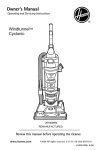
USER MANUAL
Gas String Trimmer
STOP
ARRÊT
ALTO
Model : MCT3362VB
For problems or questions, DO NOT return
this product to the store. Contact your
Customer Service Agent .
En cas de problèmes ou pour des questions,
NE PAS retourner ce produit au point de vente. S'adresser
au préposé du Service à la clientèle en composant.
SAFETY
OPERATION
MAINTENANCE
Para problemas o preguntas, NO devolver este producto a la tienda
Contacte a su Agente de Servicio al Cliente.
McCulloch U.S.A.
12802 Leffingwell Rd.
Santa Fe Springs,
CA 90670
USA
For Consumer Assistance Please Call
L'Aide Du Consommateur Necessitez S'il Vous Plait
Para La Ayuda Del Consumidor Llame Por Favor
U.S.A. & CANADA
1-800-521-8559
WARNING • PLEASE READ
Made in China / Fabriquè à Chine / Hecho en China
For your own safety please read this manual before attempting to operate your new unit. Failure to follow instructions can result in serious personal injury. Spend a few moments to familiarize yourself with
your trimmer before each use.
PN 9096-3362xx
Printed in China
INTRODUCTION
PLEASE READ
TABLE OF CONTENTS
Dear Customer,
1
GENERAL INFORMATION . . . . . . . . . . . . . . . . . . . . . . . . . .3
1-1. General Identification
1-2. Safety Features
1-3. Specifications
2 SAFETY PRECAUTIONS . . . . . . . . . . . . . . . . . . . . . . . . . . . .5
2-1. What To Do
2-2. What Not To Do
2-3. International Symbols
3 ASSEMBLY INSTRUCTIONS . . . . . . . . . . . . . . . . . . . . . . . . .7
3-1. “P” Handle Assembly
3-2. Debris Shield
3-3. Stringhead Installation
4 FUEL AND LUBRICATION . . . . . . . . . . . . . . . . . . . . . . . . . .8
4-1. Fuel
4-2. Mixing Fuel
4-3. Fuel Mixing Table
4-4. Recommended Fuels
4-5. Fuel and Lubrication Symbols
5 OPERATING INSTRUCTIONS . . . . . . . . . . . . . . . . . . . . . . . .9
5-1. Shoulder Harness
5-2. Starting a Cold Engine
5-3. Warm Engine Start
5-4. To Stop Engine
5-5. Idling/Carburetor Adjustment
6 TRIMMING INSTRUCTIONS . . . . . . . . . . . . . . . . . . . . . . . .11
6-1. Additional Safety Precautions
6-2. Stringhead Line Release
6-3. Trimming Procedures
7 MAINTENANCE INSTRUCTIONS . . . . . . . . . . . . . . . . . . . .13
7-1. Replacing Cutting Line
7-2. Air Filter
7-3. Fuel Cap / Fuel Filter
7-4. Carburetor Adjustment
7-5. Spark Plug
7-6. Spark Arrester Screen
7-7. Debris Shield Knife Sharpening
7-8. Storing a Unit
7-9. Removing a Unit From Storage
8 TROUBLESHOOTING THE ENGINE . . . . . . . . . . . . . . . . . .17
9 TROUBLESHOOTING THE STRINGHEAD . . . . . . . . . . . . .18
10 TWO YEAR LIMITED WARRANTY . . . . . . . . . . . . . . . . . . .19
Thank you for purchasing a McCulloch product. With proper operation and maintenance, it will provide you with years
of service.
In order to make the best use of your investment, be CERTAIN to familiarize yourself with the contents of the
ENTIRE user manual before attempting to operate and
maintain your unit.
Be sure to carefully follow the step-by-step instructions in
this manual to start, operate and maintain your new product.
In the manual there will be the following call-outs: NOTE:,
WARNING / CAUTION and WARRANTY.
A NOTE: is used to convey additional information, to highlight a particular explanation, or to expand a description.
A WARNING or CAUTION identifies a procedure which, if
not undertaken or if improperly done, can result in serious
personal injury and/or damage to the unit.
(WARRANTY SYMBOL) serves notice that unless
The
instructions or procedures are followed, any damage
caused will void the warranty and repairs will be at owner’s
expense.
Pay particular attention to the safety precautions. They are
written for your protection and contain important information you must know to safely operate your trimmer.
FOR WARRANTY OR SERVICE CONTACT THE NEAREST
McCULLOCH AUTHORIZED SERVICE CENTER - LOCATE
YOUR NEAREST SERVICE CENTER BY CALLING THE
TOLL FREE NUMBER IN THIS MANUAL.
2
1 - GENERAL INFORMATION
8
16
7
5
6
4
12
11
13
9
15
14
3
1
10
2
1-1. GENERAL IDENTIFICATION
1.
2.
3.
4.
5.
6.
7.
8.
9.
10.
11.
12.
13.
14.
15.
16.
1-2. SAFETY FEATURES
Numbers preceding the descriptions correspond to numbers above to help you locate the safety feature.
3 DEBRIS SHIELD must be installed to prevent debris
from being thrown at the USER and prevent the
string from extending longer than necessary.
13 MUFFLER SHIELD helps prevent hands, body and/or
combustible materials from making contact with a hot
muffler.
15 SPARK ARRESTER SCREEN retains carbon and
other flammable particles over 0.023" (.6 mm) in size
from exhaust flow.
NOTE: Compliance with local, state and federal laws
and/or regulations governing the use of a spark arrester
screen is the user’s responsibility. See Safety
Precautions (Section 3) and Maintenance Instructions
(Section 8) for additional information.
BUMP FEED HEAD *
CUTTING LINE *
DEBRIS SHIELD *
DRIVE SHAFT ASSEMBLY
P-HANDLE
THROTTLE TRIGGER
IGNITION ON/OFF SWITCH
SAFETY TRIGGER
CHOKE LEVER
FUEL TANK
AIR FILTER COVER
STARTER HANDLE
MUFFLER SHIELD
PRIMER BULB
SPARK ARRESTER SCREEN *
HARNESS
3
1 - GENERAL INFORMATION
1-3. SPECIFICATIONS
Engine Type . . . . . . . . . . . . . . . . . . . . . . . . . . . . . . . . . . . . . . . . .Air-cooled, 2-Cycle, Chrome Cylinder
Displacement . . . . . . . . . . . . . . . . . . . . . . . . . . . . . . . . . . . . . . . .26cc / 1.8ci
Dry Weight . . . . . . . . . . . . . . . . . . . . . . . . . . . . . . . . . . . . . . . . . .13.64 lbs. / 6.2 kg
Fuel Capacity . . . . . . . . . . . . . . . . . . . . . . . . . . . . . . . . . . . . . . .550 ml
Drive Shaft Length . . . . . . . . . . . . . . . . . . . . . . . . . . . . . . . . . . . .52” (132cm)
Cutting Swath . . . . . . . . . . . . . . . . . . . . . . . . . . . . . . . . . . . . . . .17" (43cm)
Handle . . . . . . . . . . . . . . . . . . . . . . . . . . . . . . . . . . . . . . . . . . . .“P” Handle
Carburetor . . . . . . . . . . . . . . . . . . . . . . . . . . . . . . . . . . . . . . . . . .Primer / Diaphragm Type
Ignition . . . . . . . . . . . . . . . . . . . . . . . . . . . . . . . . . . . . . . . . . . . . .Electronic
Drive . . . . . . . . . . . . . . . . . . . . . . . . . . . . . . . . . . . . . . . . . . . . . .Clutch
Maximum Engine Performance . . . . . . . . . . . . . . . . . . . . . . . . . .0.78 kW
Maximum RPMS at Wide Open Throttle . . . . . . . . . . . . . . . 8500 min
Idle Speed With no Stringhead Movement. . . . . . . . . . . . . . . . . .3000 min
4
2 - SAFETY PRECAUTIONS
2-1. WHAT TO DO
2-2. WHAT NOT TO DO
READ YOUR USER MANUAL AND ALL SUPPLEMENTS
(IF ANY ENCLOSED) THOROUGHLY BEFORE OPERATING YOUR UNIT.
1. CLOTHING - Always wear heavy, long pants, boots,
gloves and long sleeve shirt. Do not wear loose clothing, jewelry, short pants, sandals, or go barefoot.
Secure hair so it is at shoulder level. Always wear a
hard hat, a safety face shield, or safety glasses for eye
protection and a good grade of ear plugs or other
sound barriers for hearing protection.
2
FUELING - Mix and pour fuel outdoors where there
are no sparks and flames. Slowly remove the fuel cap
only after stopping the engine. Do not smoke while
fueling or mixing fuel. Wipe spilled fuel from the unit.
Move at least 30 ft (9m) away from the fueling source
(gas can) and site before starting unit.
3. COMPLY WITH ALL FIRE PREVENTION REGULATIONS. COMPLIANCE WITH ALL LOCAL, STATE,
OR FEDERAL LAWS IN THE UNITED STATES IS
THE USER’S RESPONSIBILITY. Your unit comes with
a spark arrester screen. Replacement spark arrester
screen kits are available at your nearest McCulloch
Authorized Service Center listed under “SAWS” in
your Telephone Directory Yellow Pages.
4. TURN UNIT OFF before setting it down.
5. ALWAYS HOLD UNIT FIRMLY WITH BOTH HANDS,
the thumb and fingers encircling the handles.
6. KEEP ALL SCREWS AND FASTENERS TIGHT.
Never operate this equipment if it is improperly adjusted or not completely and securely assembled.
7. KEEP HANDLES DRY, clean and free of fuel mixture.
8. KEEP STRINGHEAD AS CLOSE TO GROUND AS
PRACTICAL. Avoid hitting small objects with stringhead. When cutting on a slope, stand below stringhead.
9. CHECK AREA YOU WILL BE TRIMMING FOR
DEBRIS that may be struck or thrown during operation.
10. KEEP ALL PARTS OF YOUR BODY AND CLOTHING
AWAY FROM STRINGHEAD when starting or running
engine. Before starting engine, make sure stringhead
will not come in contact with any obstacle.
11. STOP ENGINE before examining cutting line.
12. STORE EQUIPMENT AWAY FROM POSSIBLE IGNITION SOURCES, such as gas-powered water
heaters, clothes dryers, or oil-fired furnaces, portable
heaters, etc.
13. ALWAYS KEEP the debris shield, stringhead, and
engine free of debris build-up.
14. OPERATION OF EQUIPMENT should always be
restricted to mature and properly instructed individuals.
1.
2.
3.
4.
5.
6.
7.
8.
9.
10.
11.
12.
13.
5
DO NOT USE ANY OTHER FUEL than that recommended in your manual. Always follow
instructions in the Fuel and Lubrication section of this
manual. Never use gasoline unless it is properly
mixed with 2-cycle engine lubricant. Permanent damage to engine will result, voiding manufacturer’s warranty.
DO NOT SMOKE while refueling or operating equipment.
DO NOT OPERATE UNIT WITHOUT A MUFFLER
and properly installed muffler shield.
DO NOT TOUCH or let your hands or body come in
contact with a hot muffler or spark plug wire.
DO NOT OPERATE UNIT IN AWKWARD POSITIONS, off balance, outstretched arms, or one-handed. Always use two hands when operating unit with
thumbs and fingers encircling the handles.
DO NOT RAISE STRINGHEAD above ground level
while unit is operating. Injury to operator could result.
DO NOT USE UNIT FOR ANY PURPOSES OTHER
than trimming lawn or garden areas.
DO NOT OPERATE UNIT FOR PROLONGED PERIODS. Rest periodically.
DO NOT OPERATE UNIT WHEN TIRED, ILL OR
UNDER THE INFLUENCE OF ALCOHOL OR
DRUGS OR MEDICATION.
DO NOT OPERATE UNIT UNLESS DEBRIS SHIELD
AND/OR GUARD IS INSTALLED AND IN GOOD
CONDITION.
DO NOT ADD, REMOVE OR ALTER ANY COMPONENTS OF THIS PRODUCT. Doing so could
cause personal injury and/or damage the unit voiding
the manufacturer’s warranty.
DO NOT operate your unit near or around flammable
liquids or gases whether in or out of doors. An explosion and/or fire may result. Never start or run the unit
inside a closed room or building, breathing exhaust
fumes can kill.
DO NOT USE ANY OTHER CUTTING ATTACHMENT. Use only Genuine McCulloch replacement parts and accessories, which are designed
specifically to enhance the performance and maximize
the safe operation of our products. Failure to do so may
cause poor performance and possible injury. Use only
the stringhead supplied with this product. Do not use any
other cutting attachment. Use of such attachments
will void your factory warranty and could result in
serious bodily injury.
2 - SAFETY PRECAUTIONS
3 - ASSEMBLY INSTRUCTIONS
2-3. INTERNATIONAL SYMBOLS
3-1. “P” HANDLE ASSEMBLY
1.
Use of these personal safety items is highly recommended to
reduce the risk of accidental injury.
2.
3-3. STRINGHEAD INSTALLATION
To install handle onto unit, you will need the following
1.
components from your user kit: “P” handle (A & B),
screws (C) and nuts (D). (Figure 3-1).
2.
Install the handle (B) on the shaft 6.0" to 7.87" (160200mm) fromthrottle and tighten the 2 screws (C) and nuts (D).
A
Install gear collar (A) ensuring that COLLAR SPACER
(B) is in place (Fig. 3-3A).
Insert holding pin (C) and thread stringhead onto
shaft. Tighten stringhead by HAND ONLY (Fig. 3-3B
and 3-3C).
A
C
B
B
3-3A
D
3-1A
Read the User Manual.
Minimum operating distance
3-2. DEBRIS SHIELD
1.
Pump the primer bulb 10 times.
2.
Remove gear collar (A) from the threaded gear housing shaft. Ensure collar spacer (B) is in place (Fig. 32A).
Install debris shield with 3 screws (C) provided (Fig. 32B).
C
3-3B
A
B
C
3-2A
3-3C
C
3-2B
6
7
4 - FUEL AND LUBRICATION
5 - OPERATING INSTRUCTIONS
4-1. FUEL
4-4. RECOMMENDED FUELS
5-1. SHOULDER HARNESS
5-2. STARTING A COLD ENGINE
Use regular grade unleaded gasoline mixed with Genuine
McCulloch 40:1 2-cycle engine oil for best results. Use mixing ratios in Section 5-3.
Some conventional gasolines are being blended with oxygenates such as alcohol or an ether compound to meet
clean air standards. Your McCulloch engine is designed to
operate satisfactorily on any gasoline intended for automotive use including oxygenated gasolines.
WARNING
NOTE: To minimize load on engine during starting and
warm-up, trim excess cutting line to 5” (13cm) (Fig. 5-2A).
1. Move ignition switch to the “RUN (I)” position (Fig. 52B).
2. Your unit is designed with a 3 position choke: CHOKE
“ ”, START “
”, and RUN “ ”. Move choke lever
to CHOKE “ ” position (Fig. 5-2C).
3. Prime the carburetor. Pump the primer bulb (A) 10
times (Fig. 5-2D).
4. Grip handle firmly – depress safety trigger (B) & throttle trigger (C) to the FULL THROTTLE position (Fig. 52E).
5. Pull starter rope until resistance is felt (about 4”) (Fig.
5-2F). A smooth rapid pull is required for a strong
spark. Pull starter rope briskly 4 times.
6. Move choke lever to START “
” position (Fig. 52G).
7. Pull starter rope again 4 times while trigger is in the
full throttle position.
8. Once engine starts, leave in the START “
” position
for 10 seconds.
9. Move the choke to RUN “ ” position (Fig. 5-2H).
10. If engine fails to start, repeat steps 1 through 9.
NOTE: If engine fails to start after repeated attempts, refer
to trouble shooting section.
NOTE: Always pull starter rope straight out. Pulling starter
at an angle will cause rope to rub against the eyelet. This
friction will cause the rope to fray and wear more quickly.
Always hold starter handle when rope retracts. Never allow
rope to snap back from extended position. This could cause
rope to snag or fray and also damage the starter assembly.
Never use straight gasoline in your unit. This will
cause permanent engine damage and void the manufacturer’s warranty for that product. Never use a fuel mixture that has been stored for over 90 days.
4-5. FUEL AND LUBRICATION SYMBOLS
If 2-cycle lubricant other than Genuine McCulloch
Lubricant is to be used, it must be a premium grade
oil for 2-cycle air cooled engines mixed at a 40:1 ratio. Do
not use any 2-cycle oil product with a recommended mixing ratio of 100:1. If insufficient lubrication is the cause of
engine damage, it voids the manufacturer’s engine warranty.
Gasoline and Oil
Mix 40:1
ALWAYS WEAR SHOULDER HARNESS when operating
unit with a blade. Attach harness to trimmer after starting
unit and engine is running at IDLE. Turn ENGINE OFF
before disconnecting shoulder harness.
1. Put the harness on so the shoulder strap is over your
LEFT shoulder.
2. Attach the harness clip (A) to the ring (B) mounted
on the shaft (Figures 5-1A and 5-1B).
3. Adjust length of shoulder strap so stringhead is parallel to the ground as it hangs from the strap. A few practice swings without starting engine should be made to
determine correct balance.
NOTE: Detach the shoulder harness from the unit before
starting engine.
4-2. MIXING FUEL
Add oil to an approved fuel container followed by the gasoline to allow incoming gasoline to mix with oil. Shake container to ensure thorough mix.
Lack of lubrication voids engine warranty. Gasoline
and oil must be mixed at 40:1.
A
4-3. FUEL MIXING TABLE
GASOLINE
McCulloch 40:1 Ratio
Lubricant
1 U.S. Gal.
3.2 oz.
95ml (cc)
5 Liters
4.3 oz.
125ml (cc)
1 lmp. Gal.
4.3 oz.
125ml (cc)
Mixing
Procedure
5-1A
B
40 Parts Gasoline to
1 Part Lubricant
1ml=1cc
5" (13cm)
5-2A
5-1B
5-2B
8
9
5 - OPERATING INSTRUCTIONS
5-3. WARM ENGINE START
5-5. IDLING/CARBURETOR ADJUSTMENT
1.
2.
3.
1. Occasionally, due to atmospheric conditions such as
altitude it might be necessary to make slight adjustment
to idle speed.
2. Insert phillips or flat screwdriver into access hole A (figure 5-5). Turn 1/8 turn clockwise to increase idle speed
and 1/8 turn counterclockwise to decrease idle speed.
4.
5.
5-2C
5 - OPERATING INSTRUCTIONS
Move ignition switch to the “RUN (I)” position.
Place choke in START “ ” position (Fig. 5-3).
Grasp throttle handle firmly, squeeze throttle trigger to
FULL position.
Pull starter rope briskly until engine starts, but no
more than 6 times. Keep throttle at FULL position until
engine runs smoothly.
If engine does not start, place choke in RUN “ ” position and pull starter rope 5 more times. If engine still
does not start it is probably flooded. Wait 5 minutes
and repeat procedure with choke in RUN “ ” position
and throttle full open.
A
5-5
6 - TRIMMING INSTRUCTIONS
A
5-2D
6-1. ADDITIONAL SAFETY PRECAUTIONS
6-2. STRINGHEAD LINE RELEASE
Before operating your unit, review ALL SAFETY PRECAUTIONS in this manual.
WARNING / CAUTION
•
B
5-3
•
5-4. TO STOP ENGINE
Release throttle trigger. Let engine return to idle. Move
switch to “STOP” position. (Fig. 5-4)
C
5-2E
DO NOT use steel wire or plastic-coated steel wire of any
kind with your stringhead. Serious operator injury can
result.
To release fresh line, run engine at full throttle and “bump”
stringhead against lawn. Line will automatically release.
The knife in debris shield will trim excess line (Figure 6-2A).
WARNING / CAUTION
5-2F
•
•
•
•
5-4
5-2G
•
IF UNFAMILIAR WITH TRIMMING techniques, practice the procedures with ENGINE in “OFF” position.
ALWAYS CLEAR WORK area of debris such as cans,
bottles, rocks, etc. Striking objects can cause serious
injury to operator or bystanders and also damage
equipment. If an object is accidentally hit, immediately
TURN ENGINE OFF and examine equipment. Never
operate unit with damaged or defective equipment.
ALWAYS TRIM OR CUT AT HIGH ENGINE SPEEDS.
Do not run engine slowly at start or during trimming
operations.
DO NOT use equipment for purposes other than trimming or mowing weeds.
NEVER raise stringhead above knee height during
operation.
DO NOT operate unit with other people or animals in
the immediate vicinity. Allow a minimum of 50 feet (15
meters) between operator and other people and animals when trimming or mowing. Allow a distance of
100 feet (30 meters) between operator and other people and animals when SCALPING with stringhead cutting.
IF OPERATING UNIT ON A SLOPE, stand below the
cutting attachment. DO NOT OPERATE on a slope or
hilly incline if there is the slightest chance of slipping
or losing your footing.
CAUTION
Be sure engine is off and string head has stopped before
attempting to remove weeds wrapped around the shaft.
Periodically weeds will wrap around the shaft. They will
need to be removed or they will prevent the shaft from
being properly cooled and could result in damage. Use a
sharp object like a screw driver to remove them. (Fig. 6-2B)
BUMP
6-2A
6-2B
5-2H
10
11
6 - TRIMMING INSTRUCTIONS
7 - MAINTENANCE INSTRUCTIONS
WARNING
6-3. TRIMMING PROCEDURES
When properly equipped with a debris shield and stringhead, your unit will trim unsightly weeds and tall grass in
those hard-to-reach areas - along fences, walls, foundations and around trees. It can also be used for scalping to
remove vegetation down to the ground for easier preparation of a garden or to clean out a particular area.
NOTE: Even with care, trimming around foundations, brick
or stone walls, curves, etc., will result in above normal
string wear.
Use extreme caution when SCALPING. Keep a distance of
100 feet (30 meters) between operator, other people and
animals during these operations.
EACH USE
ITEM
SCALPING
Scalping refers to removal of all vegetation down to the
ground. To do this, tilt the stringhead to about a 30 degree
angle to the left. By adjusting the handle you will have better control during this operation. Do not attempt this procedure if there is any chance flying debris could injure operator, other people or cause damage to property (Figure 63B).
TRIMMING / MOWING
Swing trimmer with a sickle-like motion from side to side.
Do not tilt the stringhead during the procedure. Test area to
be trimmed for proper cutting height. Keep stringhead at
same level for even depth of cut (Figure 6-3A).
HOURS OF
OPERATION
MAINTENANCE CHECKLIST
ACTION
10
SCREWS / NUTS / BOLTS
INSPECT / TIGHTEN
AIR FILTER
CLEAN OR REPLACE
FUEL FILTER
REPLACE
SPARK PLUG
CLEAN / ADJUST / REPLACE
SPARK ARRESTER SCREEN
CLEAN OR REPLACE
✔
INSPECT
✔
20
✔
✔
✔
✔
FUEL HOSES
*REPLACE AS REQUIRED
INSPECT
6-3B
✔
STRINGHEAD
*REPLACE AS REQUIRED
WARNING
*Recommended maintenance by an McCulloch authorized service center technician using Genuine Factory McCulloch Replacement parts
DO NOT SWEEP WITH TRIMMER
6-3A
Sweeping refers to tilting stringhead to sweep away debris
from walkways, etc. Your trimmer is a powerful tool and
small stones or other such debris may be hurled 50 feet (15
meters) or more, causing injury or damage to nearby property such as automobiles, homes and windows.
CLOSER TRIMMING
Position trimmer straight ahead with a slight tilt so bottom
of stringhead is above ground level and string contact
occurs at proper cutting point. Always cut away from operator. Do not pull trimmer in toward operator.
FENCE / FOUNDATION TRIMMING
Approach trimming around chain link fences, picket fences,
rock walls and foundations slowly to cut close without whipping string against the barrier. If the string comes in contact
with rock, brick walls, or foundations, it will break or fray. If
string snags fencing, it will snap off.
TRIMMING AROUND TREES
Trim around tree trunks with a slow approach so string
does not contact bark. Walk around the tree trimming from
left to right. Approach grass or weeds with the tip of the
string and tilt stringhead slightly forward.
12
13
7 - MAINTENANCE INSTRUCTIONS
7 - MAINTENANCE INSTRUCTIONS
7-1. REPLACING CUTTING LINE
7-2. AIR FILTER
7-3. FUEL CAP / FUEL FILTER
1.
CAUTION
CAUTION
NEVER operate trimmer without the air filter. The air filter
must be kept clean. If it becomes damaged, install a new filter.
To Clean Air Filter:
1. Remove knob (A) holding air filter cover in place,
remove cover (B) and lift filter (C) from air box (Figure
7-2A).
2. Wash filter in soap and water. DO NOT USE GASOLINE!
3. Air dry filter.
4. Reinstall filter.
NOTE: Replace filter if frayed, torn, damaged or unable to
be cleaned.
Remove fuel from unit and store in approved container
before starting this procedure. Open fuel cap slowly to
release any pressure which may have formed in fuel tank.
NOTE: Keep vent (A) on fuel cap clean of debris (Figure 73A).
Fuel Filter:
1. Completely remove fuel cap from fuel tank (B) to be
able to remove fuel filter (C) from tank. (Figure 7-3B)
2. Pull filter (D) off with a twisting motion. (Figure 7-3C)
3. Replace fuel filter (D). (Figure 7-3C)
NOTE: Never operate the trimmer without the fuel filter. Internal engine damage could result!
Turn the knob (A) CLOCKWISE and remove it (Figure
7-1A).
2. Remove the spool (C), and spring (D) from spindle (E)
3. Remove any remaining cutting line.
4. Double a 32' (9.8m) length of .095 or .105" (.24 or
.27cm) cutting line. Place the looped center in one of
the slots of the spool divider (Figure 7-1B).
5. Wind as shown in illustration (Figure 7-1C), keeping
tension, with each half separated by the spool divider.
Wind to within 6" (15cm) of the ends.
6. Lock each end of line into a slot (G) on opposite sides
of the spool (Figure 7-1D).
7. Install the spring (D) over the spindle (E). Insert each
end of the line through an eyelet (H) in the housing (F)
(Figure 7-1E).
8. Lower the spool into the housing (E) while feeding the
line through the eyelets (H). Ensure the spring seats
itself into the spool (Figure 7-1E).
9. Once the spool is in place, apply pressure on the spool
compressing the spring. Pull each end of the line (B)
sharply to unlock the line from the slots (Figure 7-1F).
10. Continue to apply pressure to the spool until the knob
can be threaded COUNTERCLOCKWISE onto the
spindle. Tighten the knob securely by hand only
(Figure 7-1H).
11. Trim the excess line to approximately 5" (13cm). This
will minimize load on engine during starting and
warm-up (Figure 7-1H).
G
7-1D
A
H
B
E
F
D
H
7-3A
A
7-1E
B
B
A
C
A.KNOB
B.CUTTING LINE
C.SPOOL
D.SPRING
E. SPINDLE
F. HOUSING
G.DIVIDER SLOTS
H.EYELETS
B
G
B
H
7-3B
B
D
C
C
E
7-1F
F
7-1G
7-2A
7-1A
D
5" (13mm)
7-1B
7-3C
7-1H
7-1C
14
15
7 - MAINTENANCE INSTRUCTIONS
8 - TROUBLESHOOTING THE ENGINE
7-4. CARBURETOR ADJUSTMENT
7-7. DEBRIS SHIELD KNIFE SHARPENING
The carburetor was pre-set at the factory for optimum performance. The only adjustment should be to idle speed see
section 5-5, Idling/Carburetor adjustment.
1. Remove cutter knife (A) from debris shield (B) (Figure
7-7A).
2. Place knife in a bench vise. Sharpen knife using a flat
file, being careful to maintain the angle of cutting edge.
File in one direction only.
7-5. SPARK PLUG
1. To remove spark plug B (figure 7-6A) for cleaning or
replacement: make sure engine is off, spark plug is cool
then grasp spark plug boot firmly and remove from
spark plug. Remove spark plug with correct spark plug
tool. Inspect, clean or replace as needed.
2. Spark plug gap = .025" (.635mm) (Figure 7-5A).
3. Torque to 105 to 130 inch pounds (12 to 15 N•m).
Connect spark plug boot.
4. If necessary, replace with Champion RZ7C or equivalent.
PROBLEM
PROBABLE CAUSE
Incorrect starting procedures.
CORRECTIVE ACTION
Follow instructions in the User Manual.
Incorrect carburetor mixture adjustment Have carburetor adjusted by a McCulloch
setting.
Authorized Service Center.
A
Unit won’t start or starts but will not run.
B
Fouled spark plug
Clean / gap or replace plug.
Fuel filter plugged.
Replace fuel filter.
Incorrect lever position on choke.
Move to RUN position.
Dirty spark arrester screen.
Replace spark arrester screen.
Dirty air filter.
Remove, clean and reinstall filter.
.025" (.635mm)
7-7A
7-8. STORING A UNIT
Failure to follow these steps may cause varnish to
form in the carburetor and difficult starting or permanent damage following storage.
1. Perform all the general maintenance recommended in
the Maintenance Section of your User Manual.
2. Clean exterior of engine, drive shaft assembly, debris
shield and stringhead.
3. Drain fuel from the fuel tank.
4. After fuel is drained, start engine.
5. Run engine at idle until unit stops. This will purge the
carburetor of fuel.
6. Allow engine to cool (approx. 5 minutes).
7. Using a spark plug wrench, remove the spark plug.
8. Pour 1 teaspoon of clean 2-cycle oil into the
combustion chamber. Pull starter rope slowly several
times to coat internal components. Replace spark plug.
9. Store unit in a cool, dry place away from any source of
ignition such as an oil burner, water heater, etc.
7-5A
7-6. SPARK ARRESTER SCREEN
1. To replace spark arrester screen (A) (Figure 7-6A), use
a needle nose pliers, pinch an edge of the spark
arrester screen. Pull the whole spark arrester screen
out.
2. Use the needle nose pliers to push in a new spark
arrester screen. Then open the pliers a little to press the
inner surface of the spark arrester screen to fasten it.
B
Unit starts, but engine has low power.
Incorrect carburetor mixture adjustment Have carburetor adjusted by a McCulloch
setting.
Authorized Service Center.
Engine hesitates.
Incorrect carburetor mixture adjustment Have carburetor adjusted by a McCulloch
setting.
Authorized Service Center.
No power under load.
7-9. REMOVING A UNIT FROM STORAGE
A
1. Remove spark plug.
2. Pull starter rope briskly to clear excess oil from combustion chamber.
3. Clean and gap spark plug or install a new spark plug
with proper gap.
4. Prepare unit for operation.
5. Fill fuel tank with proper fuel / oil mixture. See Fuel and
Lubrication Section.
7-6A
Runs erratically.
Incorrectly gapped spark plug.
Incorrect carburetor mixture adjustment Have carburetor adjusted by a McCulloch
setting.
Authorized Service Center.
Smokes excessively.
Incorrect fuel mixture
16
Clean / gap or replace plug.
17
Use properly mixed fuel (40:1 mixture).
9 - TROUBLESHOOTING THE STRINGHEAD
PROBLEM
PROBABLE CAUSE
Line is tangled inside stringhead.
Line won’t feed
10 - TWO YEAR LIMITED WARRANTY
SOLUTION
Remove spool from unit; disassemble.
Untangle line and wind correctly in
direction indicated on spool (see
Section 7-1).
Upon removing spool, line appears to
be melted together.
Trim off damaged line and rewind line
(see Section 7-1).
Line wound in wrong direction inside
stringhead.
Remove spool. Check to be certain line
is wound in direction indicated on line
element (see Section 7-1).
Insufficient line inside stringhead.
Remove spool and install new line (see
Section 7-1).
Internal damage to stringhead caused
by bumping too hard on ground while
advancing line.
Disassemble stringhead and examine
parts for damage. Replace parts or
entire head (see Section 7-1).
Improper trimming procedures, or poor
quality line.
See Trimming Procedures (see section
6-3) or replace line (see section 7-1)
Unable to remove stringhead knob.
Stringhead knob overtightened.
Use anti-seize compound and reinstall
knob HAND TIGHT ONLY.
Stringhead and shaft are hot to the
touch.
Weeds wrapped around shaft
Remove weeds (see Section 6-2).
Line snaps off or frays.
18
1. DURATION
The duration of the warranty for this McCulloch product is as follows: TWO (2) YEARS from date of original purchase only
when used for personal, family, household, farm or ranch, purposes, provided the unit is not used for rental purposes;
NINETY (90) DAYS from date of original purchase when used for commercial, professional, institutional or rental purposes. This warranty gives you specific legal rights. You may also have other rights which vary from state to state. MCCULLOCH CORPORATION HEREBY DISCLAIMS ALL IMPLIED WARRANTIES AFTER THE APPLICABLE EXPIRATION
DATES OF THIS EXPRESS LIMITED WARRANTY. (Some states do not allow limitations on how long an implied warranty lasts, so the above limitations may not apply to you.)
2. WHO GIVES THIS WARRANTY
McCulloch U.S.A
1-800-521-8559
12802 Leffingwell Rd. Santa Fe Springs, CA 90670 USA
3. WHO RECEIVES THIS WARRANTY
A. The buyer (other than for purposes of resale) of the McCulloch Product.
B. Any person to whom such product is lawfully transferred within the duration of the implied or written warranty applicable to the product.
C. Any other person who is entitled by the terms of the warranty or under applicable state law to enforce against the
Warrantor the obligation of the warranty.
(The above mentioned parties are hereinafter referred to as “User.”)
4. WHAT IS COVERED UNDER THIS WARRANTY
Any failure that occurs within the applicable duration of the warranty period that is the result of defects in materials or workmanship. All work must be preformed by a McCulloch Authorizedd Service Center.
5. WHAT IS NOT COVERED UNDER THIS WARRANTY
A. Any incidental or consequential damages that may result from the failure or malfunction of the McCulloch product.
(Some states do not allow the exclusion or limitation of incidental or consequential damages, so these limitations may
not apply to you.)
B. Any failure that results from an accident, User abuse, neglect or failure to operate the product in accordance with the
instructions provided in the User Manual(s) supplied with the product, or that results from improper servicing by an
unauthorized repair facility.
C. Normal adjustments or wear items which are explained in the User Manual(s) provided with the product.
D. Any component(s) or accessories not sold or manufactured by the Warrantor.
E. Predelivery setup or assembly of units.
F. This warranty does not apply to accessories, normal maintenance, wear items or adjustment(s) of the product set forth
in the User Manual(s).
6. RESPONSIBILITIES OF THE WARRANTOR UNDER THIS WARRANTY
A. Repair or replace components which have failed within the duration of the applicable warranty period at no cost to the
User.
B. Ensure that the McCulloch Authorized Service Center is reimbursed for parts and labor costs incurred due to performance
of a warranty repair in accordance with established warranty policies and procedures.
7. RESPONSIBILITIES OF THE USER UNDER THIS WARRANTY
A. The User must deliver or ship the McCulloch product covered under this warranty to the dealer from whom it was originally purchased or to the nearest McCulloch Authorized Service Center. Proof of purchase is required.
B. Freight costs, if any, will be borne by the user.
C. Use reasonable care in maintenance, operations and storage of the product as explained in the User Manual(s).
8. WHEN WARRANTOR WILL PERFORM OBLIGATION UNDER THIS WARRANTY
A. Repair of warrantable products will be scheduled according to the normal work flow at the servicing location, depending on the availability of replacement parts.
B. Repair time which exceeds ten (10) days from the time the product was delivered to the service center will extend
the warranty coverage by the number of days the product remains inoperable.
C. If User does not receive satisfactory results from local service center, User must contact McCulloch Corporation, by
calling our toll-free telephone number.
19