1
DataFW4 / DATAREG
Data logger
User Manual
Doc.-No: E122209209002
Baer Industrie-Elektronik GmbH
Rathsbergstr. 23
D-90411 Nürnberg
Phone: +49 (0)911 970590
Fax: +49 (0)911 9705950
Internet: www.baer-gmbh.com
COPYRIGHT
Copyright © 2009
BÄR Industrie-Elektronik GmbH
All rights, including those originating from translation, (re)-printing and copying of this document
or parts thereof are reserved. No part of this manual may be copied or distributed by electronic,
mechanic, photographic or indeed any other means without prior written consent of
BÄR Industrie-Elektronik GmbH. All names of products or companies contained in this
document may be trademarks or trade names of their respective owners.
Note
Based on its policies,
BÄR Industrie-Elektronik GmbH develops and improves their
products on an ongoing basis. In consequence,
BÄR Industrie-Elektronik GmbH
preserve the right to modify and improve the software product described in this document.
Specifications and other information contained in this document can change without prior notice.
This document does not cover all functions in all possible detail or variations that may be
encountered during installation, maintenance and usage of the software.
Under no circumstances whatsoever will
BÄR Industrie-Elektronik GmbH accept
any liability for mistakes in this document or for any sub sequential damage arising from
installation or usage of the software.
BÄR Industrie-Elektronik GmbH preserves the right to modify or withdraw this
document at any time without prior announcement.
BÄR Industrie-Elektronik GmbH does not accept any responsibility or liability for the
installation, usage, maintenance or support of third party products.
Printed in Germany
Table of Contents
1
General Information.............................................................................................. 9
1.1 Performance features..................................................................................................10
1.2 System overview .........................................................................................................11
1.2.1
The central processing unit (CPU1):...................................................................11
1.2.2
The recording and communication unit (CPU2): .................................................12
1.2.3
Pulse and control input cards (IEA08) ................................................................12
1.2.4
Pulse and control output cards (IEA08) ..............................................................12
1.2.5
Power supply unit ...............................................................................................12
1.2.6
Communication unit............................................................................................13
1.2.7
Radio clock (DCF77 / GPS)................................................................................13
1.2.8
Analogue signal current input cards (IF8120) .....................................................13
1.2.9
CENTRONICS interface for external printer .......................................................13
1.2.10 RS232 interface for load check...........................................................................13
1.3 Block diagram DataFW4 .............................................................................................14
1.4 Software......................................................................................................................15
1.5 System........................................................................................................................16
1.5.1
Parameterization ................................................................................................16
1.5.2
Inbuilt Self-Test ..................................................................................................16
1.6 Metered value processing ...........................................................................................17
1.6.1
Pulse inputs........................................................................................................17
1.6.2
Energy and demand registers.............................................................................17
1.6.3
Summation .........................................................................................................17
1.6.4
Import/export calculations (summation balance).................................................18
1.6.5
Hysteresis ..........................................................................................................18
1.6.6
Pulse outputs .....................................................................................................18
1.6.7
Maximum demand calculation ............................................................................18
1.6.8
Maximum demand reset .....................................................................................19
1.6.9
Historical MD values...........................................................................................19
1.6.10 Power factor cos(ϕ) ............................................................................................19
1.6.11 Heat meter (option) ............................................................................................19
1.6.12 Schematic of the metered value processing sequence .......................................20
1.7 Time management ......................................................................................................21
1.7.1
Real time clock ...................................................................................................21
1.7.2
Automatic summer/winter time changeover ........................................................21
1.7.3
Radio clock.........................................................................................................21
1.7.4
Automatic summer/winter time and radio clock...................................................22
1.7.5
Measuring period (Tm) .......................................................................................22
1.7.6
Sliding measuring period ....................................................................................22
1.7.7
Starting the measurement ..................................................................................22
1.7.8
End of measurement ..........................................................................................22
1.7.9
Recording break (interruption) ............................................................................22
1.8 Tariff rate dependent processing.................................................................................23
1.8.1
Tariff control .......................................................................................................23
1.8.2
Tariff rate calendar .............................................................................................23
1.8.3
Tariff rate inputs .................................................................................................25
1.8.4
Tariff identifiers...................................................................................................25
1.9 Measured value memory.............................................................................................26
Table of Contents
1.9.1
Cyclic buffer ....................................................................................................... 26
Only the first 32 inputs can be stored in the buffers! ........................................................ 26
1.9.2
Storage of the sums........................................................................................... 26
1.10 Pulse and signal outputs .......................................................................................... 27
1.10.1 Tariff rate output................................................................................................. 27
2
Module Description ............................................................................................ 28
2.1 Keyboard with LCD display......................................................................................... 29
2.1.1
RS232 (V.24) service interface .......................................................................... 29
2.1.2
LED display on CPU .......................................................................................... 30
2.1.3
LCD Display....................................................................................................... 30
2.1.4
LCD test............................................................................................................. 31
2.1.5
Roll display ........................................................................................................ 31
2.2 MemoryCard module MSC01...................................................................................... 32
2.2.1
Inserting the memory card ................................................................................. 33
2.2.2
Removing the memory card ............................................................................... 33
2.2.3
LED on the front................................................................................................. 33
2.2.4
Notes on handling the memory card................................................................... 33
2.2.5
Battery supply .................................................................................................... 34
2.2.6
Formatting the memory card .............................................................................. 34
2.2.7
Number of integration period entries .................................................................. 35
2.2.8
Writing to the memory card ................................................................................ 36
2.3 Memory module DS01 ................................................................................................ 37
2.4 VU25 Unit ................................................................................................................... 38
Number of integration period entries................................................................................ 38
2.5 VU26 Unit ................................................................................................................... 40
Number of integration period entries................................................................................ 41
2.6 Input and output boards .............................................................................................. 42
2.6.1
Input board IEA08 .............................................................................................. 44
2.6.2
Analogue input board IF8120 ............................................................................. 44
2.6.3
Control inputs..................................................................................................... 45
2.6.4
Logical inputs..................................................................................................... 45
2.6.5
Outputs .............................................................................................................. 45
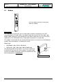
2.7 Modem ....................................................................................................................... 46
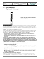
2.8 DCF77 radio clock ...................................................................................................... 48
2.9 GPS satellite receiver clock ........................................................................................ 50
2.10 MODA02 interface board.......................................................................................... 52
2.11 M-Bus adapter board MBUS-DFW01 ....................................................................... 53
3
Installation and Commissioning ....................................................................... 54
3.1 Scope on delivery ....................................................................................................... 54
3.2 Default setting on restart............................................................................................. 54
3.3 Installation of the device ............................................................................................. 55
3.3.1
Connection......................................................................................................... 55
3.3.2
Installation procedure......................................................................................... 55
3.3.3
Transport and subsequent commissioning ......................................................... 56
3.4 Battery replacement.................................................................................................... 56
3.4.1
Main unit CPU1.................................................................................................. 57
3.4.2
VU26 unit ........................................................................................................... 57
Table of Contents
3.4.3
MemoryCard ......................................................................................................57
3.5 Program protection switch...........................................................................................58
3.5.1
Open the main unit .............................................................................................58
3.5.2
Set the program protection switch ......................................................................58
4
Operation............................................................................................................. 59
4.1 Standard display .........................................................................................................59
4.2 Menu structure ............................................................................................................63
4.3 Fault display................................................................................................................64
4.3.1
Calling up the fault display..................................................................................65
4.3.2
LED display on CPU...........................................................................................65
4.4 Main Menu ..................................................................................................................66
4.4.1
Information (Info: Inputs) ....................................................................................67
4.4.1.1
Counter value ...............................................................................................67
4.4.1.2
Summation registers (SUM) .........................................................................68
4.4.1.3
Pulse ratio ....................................................................................................68
4.4.1.4
Maximum demand (inputs/channels INP) .....................................................68
4.4.1.5
Maximum demand (summation register SUM) ..............................................68
4.4.1.6
Reset list (inputs/channels INP)....................................................................69
4.4.1.7
Reset list (summation register SUM) ............................................................69
4.4.1.8
Storage medium ...........................................................................................69
4.4.1.9
Cos (PHI)......................................................................................................70
4.4.1.10
Number of resets ........................................................................................70
4.4.1.11
Version designation ....................................................................................70
4.4.2
Parameterization via the keypad ........................................................................71
4.4.2.1
Restart (Factory settings) .............................................................................72
4.4.2.2
Printer mode.................................................................................................73
4.4.2.3
Baud rate......................................................................................................74
4.4.2.4
Date..............................................................................................................74
4.4.2.5
Time .............................................................................................................74
4.4.2.6
Radio clock (for Germany only) or GPS........................................................75
4.4.2.7
Summer time ................................................................................................75
4.4.2.8
SYNC input...................................................................................................75
4.4.2.9
Unit identifier (ID)..........................................................................................75
4.4.2.10
Station address...........................................................................................75
4.4.2.11
Number of inputs ........................................................................................75
4.4.2.12
Number of summation registers..................................................................76
4.4.2.13
Number of tariffs .........................................................................................76
4.4.2.14
Input quantization .......................................................................................76
4.4.2.15
Counter value .............................................................................................77
4.4.2.16
Summation registers...................................................................................77
4.4.2.17
Maximum resets .........................................................................................79
4.4.2.18
Periodic buffers for inputs ...........................................................................79
Table of Contents
4.4.2.19
Periodic buffers for summation register ...................................................... 79
4.4.2.20
Integration period Tm ................................................................................. 80
4.4.2.21
Starting time............................................................................................... 80
4.4.3
Recording break................................................................................................. 81
4.4.4
Maintenance ...................................................................................................... 83
4.4.5
Printing .............................................................................................................. 83
4.4.6
Delete errors ...................................................................................................... 84
4.4.7
Periodic buffer shows......................................................................................... 84
4.4.8
Register address shows..................................................................................... 85
4.5 Language selection..................................................................................................... 86
5
Setting the pulse ratios ...................................................................................... 87
5.1 Pulse ratios of the metered value inputs ..................................................................... 87
5.1.1
Digital inputs (pulses)......................................................................................... 87
5.1.2
Signal current inputs .......................................................................................... 89
5.1.3
Customer-specific inputs (if heat meter) ............................................................. 90
5.2 Pulse ratios of the summation registers ...................................................................... 91
5.2.1
Digital inputs (pulses)......................................................................................... 91
5.2.2
Digital outputs (pulses)....................................................................................... 92
5.2.3
Hysteresis .......................................................................................................... 92
6
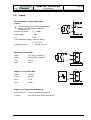
Technical Data .................................................................................................... 93
6.1
6.2
6.3
6.4
6.5
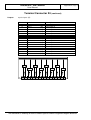
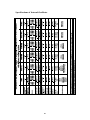
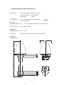
Housing dimensions ................................................................................................... 93
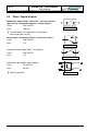
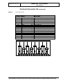
Nominal voltage .......................................................................................................... 94
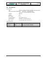
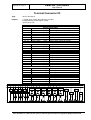
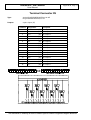
Inputs.......................................................................................................................... 95
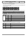
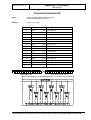
Pulse / Signal outputs ................................................................................................. 96
Accessories ................................................................................................................ 97
Table of Contents
Appendix A ..........................................................................Communication Protocols
SCTM protocol ................................................................................................................... A 2
LSV1 procedure ............................................................................................................... A 33
IEC-60870-5-102 protocol ................................................................................................ A 36
Load prognosis (load check) ............................................................................................ A 38
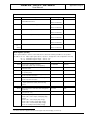
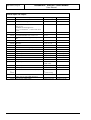
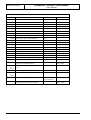
Appendix B .................................................................................... Register Addresses
Service interface description .............................................................................................. B 2
Register addresses ............................................................................................................ B 2
Appendix C ........................................................ Parameter List und Constant Sheets
Parameter list ..................................................................................................................... C 3
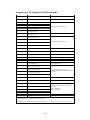
Constant sheet for devices with 8 inputs and 4 outputs max .............................................. C 7
Constant sheet for devices with 16 inputs and 8 outputs max ............................................ C 7
Constant sheet for devices with 32 inputs and 8 outputs max ............................................ C 8
Constant sheet for devices with 48 inputs and 8 outputs max ............................................ C 9
PTB: Type-approval certificate
Appendix D ...................................................................................Terminal Connection
Terminal View .................................................................................................................... D 2
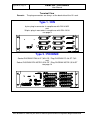
Type 1 / DIN ....................................................................................................................... D 3
Type 2 / PHOENIX ........................................................................................................... D 14
Appendix E (option) ......................................................................................GPS170SV
Technical Information / Operating Instructions.................................................................... E 3
Table of Contents
DataFW4 / DATAREG
User Manual
Page 9
Bär Industrie-Elektronik GmbH ⋅ Rathsbergstr. 23 ⋅ D-90411 Nürnberg ⋅ Phone 0911/970590 ⋅ Fax +49 911 9705950
1
General Information
The DataFW4 / DATAREG family was designed as a powerful device for the registration and
processing of electrical impulses from energy meters, flow meters, heat flow processors and
similar devices. It is meant for installation in bulk energy supply points, power station injection
points, at special contract customers and industrial premises. Load profiles, calculated values
and spontaneous events are processed and stored on the site. This data can be interrogated
by hierarchically higher processing devices via a number of interfaces.
Page 10
DataFW4 / DATAREG
User Manual
Bär Industrie-Elektronik GmbH ⋅ Rathsbergstr. 23 ⋅ D-90411 Nürnberg ⋅ Phone 0911/970590 ⋅ Fax +49 911 9705950
1.1
Performance features
• Setting parameter values via the service interface of your PC
• Keyboard operation (menu driven)
• Processing of analogue and digital measured values
• Pulse inputs, 48 maximum
• Logical inputs, 4 maximum
• Eight summation registers (in one energy direction), or 8 summation balance registers
• Measuring period output:
− Switched by radio-controlled clock, fixed measuring period (15 minutes) - other periods
available on request
− Switched by DataFW4, freely selectable measuring periods (1 min. to 1 hour)
• Pulse outputs, 8 maximum
• Data capture of energy and maximum tariffs
• Maximum inhibit and reset
• Store data of the last 12 resets
• Marking of measured values
• Built-in real time clock, active when radio-controlled clock fails or when DataFW4 has no
radio-controlled clock.
• Built-in radio-controlled clock DCF77 with tariff calendar, fixed program (option)
• Tariff calendar (freely programmable)
• Automatic switch to summer and winter time, or standard time
• Parameterization switching times as desired over 5 years
• Freely selectable measuring periods in DataFW4 (1 min. to 1 hour), standard 15 min.
• Recording power failures
• Battery backed data saving in case of power failure (exchangeable, data storage 10 years)
• Protection against unauthorized manipulation through separate passwords for setting
parameters, maximum-reset, change of data carrier and system restart
• Saving measured values (depending on equipment specification) in a ring memory (7 to 35
days), external printer or direct transmission from your PC via modem or RS232 interface.
• The language used for operating can be selected (English, German, French, Dutch/Flemish,
Polish)
• Load check (30 sec. or 1 min.)
• Heat meter reading (option)
DataFW4 / DATAREG
User Manual
Page 11
Bär Industrie-Elektronik GmbH ⋅ Rathsbergstr. 23 ⋅ D-90411 Nürnberg ⋅ Phone 0911/970590 ⋅ Fax +49 911 9705950
1.2
System overview
The DataFW4 is a modular built telecounting instrument intended for use in the electricity, gas
and water supply industries. It processes, evaluates, displays and records the pulses received
from energy meters. The received pulses are used to calculate e.g. the demand values that are
saved in the measured value memories (periodic buffers) at the end of every measuring
period. At the same time the corresponding energy values are cumulated in separate registers.
The local equipment usually works together with a remote metering central station that
periodically reads the stored demand values via remote interrogation and evaluates them.
The DataFW4, in its minimal configuration, consists of the following components:
1.2.1 The central processing unit (CPU1):
• Processor: TMP 68301
• RAM: 256kByte
• ROM: 512kByte
• Data backup: Lithium battery
• receives pulses and converts them into the corresponding demand or energy unit (for
example kW, kWh, kvar)
• sends the results of this conversion to the memory and communication unit
• calculates and stores the demand maxima (value and time)
• summates the received pulses
• sends the summation results to the pulse outputs
• does special calculations, for example power factor cos(phi) for individual inputs and sums
• manages time, for example automatic switch over from winter time to summer time, tariff
calendar etc
• interrogates the control inputs and sets the control outputs
• communicates with the user via the keyboard, the LCD-display or the service interface
• controls the external printer (option)
Page 12
DataFW4 / DATAREG
User Manual
Bär Industrie-Elektronik GmbH ⋅ Rathsbergstr. 23 ⋅ D-90411 Nürnberg ⋅ Phone 0911/970590 ⋅ Fax +49 911 9705950
1.2.2 The recording and communication unit (CPU2):
Three variants are available. All of them can store the demand values into two periodic buffers
and transmit the contents of the periodic buffers, by means of a serial interface or a MODEM,
to a remote metering central station using a high security “Serial Code Telemetering (SCTM)”
protocol.
The events (for example register overflow, the change of important system parameters, etc)
and the time when they appear are saved in a buffer for events (spontaneous buffer).
Details of each variant:
• Memory card recording module (MSC01)
In addition to the internal periodic buffers this rack-mounted module has a plug-in slot for a
memory card to the PCMCIA/JEIDA Standard. The contents of the periodic and
spontaneous buffers as well as some of the device parameters are stored a second time on
the memory card. The memory card can be read by any PC via a commercially available
reader unit.
• Recording unit (DS01)
This unit has no external recording medium but it has two internal RS232 serial interfaces
that permits a local communication with a program that evaluates the data saved in the
internal buffers.
• Recording unit with a RS232 serial interface (VU25/VU26)
This unit has no external recording medium but it has a VRS232 serial interface that permits
a local communication with a program that evaluates the data saved in the internal buffers.
You can get some more information about these four variants of recording and communication
units in the corresponding chapters in the main part of these operating instructions.
1.2.3 Pulse and control input cards (IEA08)
These cards convert the pulse forms, respectively the voltage levels, that are used in remote
metering, (e.g. momentary: IEW, S0: IES, bipolar current pulses: IED) into the TTL levels that
are used by the CPU:
• max. 48 pulse inputs (IEW, IES, IED)
• max. 7 control inputs (IES)
• max. 4 logical inputs (IES)
1.2.4 Pulse and control output cards (IEA08)
These cards convert from TTL-levels into the voltage levels that are used in remote metering:
• max. 8 outputs (IAW)
1.2.5 Power supply unit
Power supply units with different auxiliary voltages are available for different versions of the
equipment and user-specific requirements. If desired, a no-break power supply can be
supplied.
• 110/230-240VAC
• 60VDC or 110VD or another (option)
DataFW4 / DATAREG
User Manual
Page 13
Bär Industrie-Elektronik GmbH ⋅ Rathsbergstr. 23 ⋅ D-90411 Nürnberg ⋅ Phone 0911/970590 ⋅ Fax +49 911 9705950
The following devices are also available on request:
1.2.6 Communication unit
The interface module for data interrogation is the connection between the internal modem
interface of the main memory and communication module and the remote metering centre.
DataFW4 provides 3 solutions for this:
• Data teletransmission by fully automated slot-in modem.
• Direct data output via the RS232 interface of the MODA02 interface card
• M-Bus adapter card.
• Fabre glass
The following protocols are available for communication:
• SCTM protocol
• LSV1 procedure
• IEC 870-5-102
1.2.7 Radio clock (DCF77 / GPS)
The radio clock receives time signals from the DCF77 transmitter in Frankfurt and then sets the
internal time.
Optional is a GPS receiver possible.
1.2.8 Analogue signal current input cards (IF8120)
These cards convert the analogue signal (0..20mA or 4..20mA) into the TTL levels that are
used by the CPU.
1.2.9 CENTRONICS interface for external printer
Instead of a built-in printer it is possible to use a CENTRONICS interface in order to connect
an external printer (compatible with EPSON FX-80; ASCII format).
1.2.10 RS232 interface for load check
As an option DataFW4 can be equipped with additional RS232 interface for 30sec/1min load
check:
• The 30sec load check is a scan of the instantaneous values of the summation registers
(maximum demand) according to DIN 19244, Part 52.
• The 1min load check is a scan of the instantaneous values of the summation registers
(energy) according to IEC 60870-5-102.
The station address, baud rate and number of values to be transmitted is set in the
parameterization software DMFPARA. See the separate description of DMFPARA for further
details.
Page 14
DataFW4 / DATAREG
User Manual
Bär Industrie-Elektronik GmbH ⋅ Rathsbergstr. 23 ⋅ D-90411 Nürnberg ⋅ Phone 0911/970590 ⋅ Fax +49 911 9705950
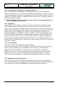
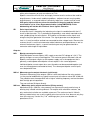
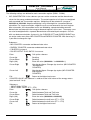
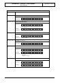
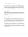
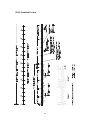
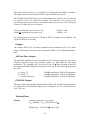
1.3
Block diagram DataFW4
The block diagram of the modules listed in Section 1.2:
Figure 1, Block diagram DataFW4
DataFW4 / DATAREG
User Manual
Page 15
Bär Industrie-Elektronik GmbH ⋅ Rathsbergstr. 23 ⋅ D-90411 Nürnberg ⋅ Phone 0911/970590 ⋅ Fax +49 911 9705950
1.4
Software
• Manages a max. of 48 meter inputs (depends on order)
• Manages a max. of 4 logical inputs
• Manages a max. of 7 control inputs (synchronization, marking of measured values,
maximum inhibit, 2 tariff signal inputs, external reset signal)
• Manages a max. of 8 outputs (e.g. measuring period output, summation registers 1-8) with
standard pulses or static signals
• Interrogation of all flagged error conditions
• Reads all registers of a meter
• Setting device parameters via a password (max. 8 digits)
• Interruption of measurements and call-up of changeover times via a password
• Entry of all meter parameters
• Entry of a freely selectable starting time
• Saving all data in case of power failure
• Calculation and check of all important data after power failure
• Data errors are marked and saved
• Power failure message
• Synchronization of real time clock, also by radio-controlled clock
• Communication with external printer
• Communication with Memory Card reader module MSC01 or recording unit
DS01/VU25/VU26
• Communication with external printer (option)
• Communication with V.24 interface for load check (option)
• Communication with heat meter (option)
Page 16
DataFW4 / DATAREG
User Manual
Bär Industrie-Elektronik GmbH ⋅ Rathsbergstr. 23 ⋅ D-90411 Nürnberg ⋅ Phone 0911/970590 ⋅ Fax +49 911 9705950
1.5
System
1.5.1 Parameterization
The DataFW4 must only be parameterized while measurement is not being performed. Some
settings are disabled while measurement is running, others can be performed but cause
problems for the evaluation of data obtained during this integration period.
Complex functions such as tariff rate calendar, summer/winter time switchover, printer texts
and power factor can only be parameterized using the DMFPARA parameterization software.
The PARAMETERIZATION menu is password-protected. However, if no password has been
installed, you can skip the prompt for the password by pressing the ENTER key again. If a
password is installed and is entered incorrectly you return to the menu item
PARAMETERIZATION automatically and can call up the function again.
To parameterize the DataFW4 connect a PC, in which the DMFPARA parameterization
software has been installed, via the RS232 service interface on the front panel of the CPU.
DataFW4 can only be comprehensively parameterized using this software. Please refer to the
operating instructions of the parameterization software supplied. Complete parameterization
via the keypad is not possible. The manufacturer accepts no responsibility for correct
parameterization.
The following functions and values can be parameterized in the DataFW4:
•
•
•
•
•
•
•
•
•
•
•
Input/output signal matching
Control inputs
Internal tariff program
Calendar and switching time data
Assignment of the cyclic buffers (integration period memory)
Integration period duration
Number of sums
Summation or summation balance calculation
Special evaluation (e.g. cos(ϕ))
Interface for data scan
Printer outputs
1.5.2 Inbuilt Self-Test
• RAM Test: the DataFW4 memory is continuously checked (over 100 times within 24 hours).
If a defective storage position is located, an error message will be displayed and the error
signal relay activated. The error message is available via remote interrogation.
• EPROM Test: the contents of DataFW4's EPROM (CPU1 and CPU2) are continuously
checked (more that 10,000 times within 24 hours). If an imbalance is detected between the
computed check sum and the saved check sum, an error message will appear in the display
and the error signal relay activated. The error message is available via remote interrogation.
DataFW4 / DATAREG
User Manual
Page 17
Bär Industrie-Elektronik GmbH ⋅ Rathsbergstr. 23 ⋅ D-90411 Nürnberg ⋅ Phone 0911/970590 ⋅ Fax +49 911 9705950
1.6
Metered value processing
1.6.1 Pulse inputs
The pulse and control inputs must have a minimum duration, which is programmable
(„debouncing“) in order to be recognized. If their duration is less than this minimum value they
will not be recorded. For the pulse inputs you may choose the duration of the pulse separately
from the duration of the interval, between 10ms and 2000ms in steps of 10ms. For the control
pulses the minimum duration of the pulses and of the intervals is fixed at 30ms minimum. The
pulse inputs can also detect pulses that are too long. Such pulses will not be counted. Pulse
monitoring may be programmed within the range from 10ms to 2000ms. It is switched off after
a system restart, i.e. the pulse lengths can be of any duration.
For activation of the inputs see the mark “#” in menu “Info Inputs / Counter Value”.
!
Only the first 32 inputs will be saved in to the periodic buffers.
1.6.2 Energy and demand registers
The incoming pulses are separately counted for energy and for maximum demand. They are
multiplied by the pulse scaling value (between 0 and 99999999/99999999) (only positive
values) and cumulated in the energy registers and demand registers separately for each tariff
(see block diagram).
In the present equipment software status the number of decades of the energy registers is set
at 8 and that of the demand registers at 4. When an energy register has reached the value
99999999 it will continue with 00000000. At the same time an error flag is set in the equipment
status register.
The maximum demand registers react differently. They remain at 9999 until the end of the
measuring period, when the demand registers are always set to 0000. When an overflow of the
demand registers occurs an error flag is also set. These error flags can be reset only by hand
or by means of the service interface.
The demand registers commence counting only after measurement has started.
1.6.3 Summation
The metering pulses fed into the inputs are scaled and can be added in up to 8 different
summators. The input scaling may be chosen between -99999999 and 99999999. Negative
scaling only makes sense for import/export calculations. It simply summating the negative
results are not recorded in the result registers. After the summation, the intermediate results
are divided by a programmed common denominator and saved in the energy or max. demand
summation registers. The energy sums also can be scaled with a separate denominator and
fed to the pulse outputs.
Page 18
DataFW4 / DATAREG
User Manual
Bär Industrie-Elektronik GmbH ⋅ Rathsbergstr. 23 ⋅ D-90411 Nürnberg ⋅ Phone 0911/970590 ⋅ Fax +49 911 9705950
1.6.4 Import/export calculations (summation balance)
When the energy flows into two directions (import/export), it is necessary to record both
directions separately. This is the reason for the import/export calculation. The inputs metered
in the positive direction (import) are scaled positively, whilst the remainder (export) are scaled
negatively. The positive values are separated from the negative values, separately registered
or fed to separate pulse outputs.
!
While summation balance calculation is active only the first 4 summation balances
can be stored in the cyclic buffers.
1.6.5 Hysteresis
The hysteresis (free-wheeling) is used only in energy summators and is active only during
import/export calculations. It processes only the metered values that are fed to the pulse
outputs. It has the function of a temporary buffer. Every pulse with a „positive“ sign causes the
contents of the free-wheeling circuit to increase and every pulse with a „negative“ sign causes
it to decrease. Pulses will appear at the output of the free-wheeling circuit only when its
programmed capacity is exceeded or the value is negative. A built-in energy direction switch
switches the impulses to the positive or negative output. The purpose of the free-wheeling
circuit is to prevent a rapid succession of pulses at the „positive“ or „negative“ outputs when
the energy flows of import and export are roughly in balance. A sensible guide value for the
capacity of the free wheeling circuit is twice the sum of the absolute values of all scalings of the
summator in question.
1.6.6 Pulse outputs
DataFW4 can output summated pulses directly and locally.
As in the case of the pulse inputs, the duration of the pulses and of the intervals of the pulse
outputs may be set between 10ms and 1000ms in steps of 10 ms. A pulse output can
temporarily store up to 1000 pulses. When this value is exceeded, an error flag in the
equipment status is set. This flag can be reset only manually by the user or via the service
interface. It is possible, by means of the software to assign a pulse output to a specific
summator. When this assignment is changed, the intermediate pulse memory is cleared.
1.6.7 Maximum demand calculation
When the measuring has been started, the DataFW4 will compare the maximum demand
value at the end of every measuring period with the largest value measured to date. If the new
value is larger, then it will be stored together with date and time when it occurred.
DataFW4 / DATAREG
User Manual
Page 19
Bär Industrie-Elektronik GmbH ⋅ Rathsbergstr. 23 ⋅ D-90411 Nürnberg ⋅ Phone 0911/970590 ⋅ Fax +49 911 9705950
1.6.8 Maximum demand reset
At the maximum demand reset all measured maximum values will be copied into the historical
list memory and the MD unit set to zero to enable a new maximum calculation. The reset can
be initiated in three ways:
• Via the control input RSTX.
• Time-controlled monthly, daily or once an hour. The exact time can be programmed.
• Manually on keyboard (secured by password)
All three modes can be separately enabled or disabled.
1.6.9 Historical MD values
The DataFW4 stores at every max. reset the following values in the historical list memory:
• Energy values since last reset
• Maximum demand values with date and time
• Lowest average cos(phi) value since last reset
These values are stored in the CPU and can be read out on the display only. If required they
can be printed. The DataFW4 stores the previous 12 maximum values.
1.6.10 Power factor cos(ϕ
ϕ)
The DataFW4 can compute the power factor cos(phi) of any input or summation registers. Any
register can be defined as being active or reactive. Up to four cos(phi) calculations are
possible. The instrument computes the average power factor over one Tm as well as the
average over an arbitrary time in the range from 1 to 60 minutes. This value will be
recalculated every minute. Results are readable on the display and can be printed out. They
are not, however, stored in the periodic buffer.
1.6.11 Heat meter (option)
Following heat meter will be supported:
•
•
•
•
Calec MB or ST (Aquametro)
Multical 610 (Kamstrup)
SensyCal (ABB)
2WR5 (Landis + Gyr or Siemens)
DataFW4 / DATAREG
Page 20
User Manual
Bär Industrie-Elektronik GmbH ⋅ Rathsbergstr. 23 ⋅ D-90411 Nürnberg ⋅ Phone 0911/970590 ⋅ Fax +49 911 9705950
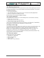
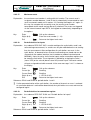
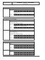
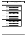
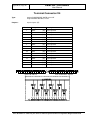
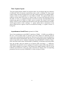
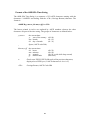
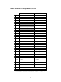
1.6.12 Schematic of the metered value processing sequence
CALEC
AUTARKON
Telegram
Pulse Input
IE1..48
H, C, D, F, P (Mean values for demand)
Energy inputs
1..48
Xw1
Yw1
Register
101-xx
102-xx
103-xx
104-xx
100-xx
Buffered value
.
.
.
Demand inputs
1..48
Xp1
Yp1
.
.
.
Register
130-xx
120-xx
Current
Last IP
Mean values for demand
400-xx Tariff rate 1
401-xx Tariff rate 2
402-xx Tariff rate 3
403-xx Tariff rate 4
Values, Time code
REG{130-xx}= IExx × REG{302-xx} ⁄ REG{303-xx}
REG{100-sx}= (ΣIExx × REG{210273-sx[00-07]}) ⁄ REG{301-sx}
1
Ywa+
Xws1
1
Xwsn
1
REG{100-xx}= IExx × REG{300-xx} ⁄ REG{301-xx}
Maximum demands
Energy sums
1 to 8
.
.
.
Tariff rate 1
Tariff rate 2
Tariff rate 3
Tariff rate 4
Bei Ergebnissen werden die entsprechenden Register
{REG} angegeben (s. Anhang B).
Für die Registeradressen sind folgende
Subadressen möglich:
xx = 00..47
Eingänge 1..48
sb = 64..71
Summe Bezug 1..8
sl = 72..79
Summe Lieferung 1..8
+
1
Yws+
H ws
Hysteresis
—
100-sb
Buffered value
1
Ywa–
1
Yws–
100-sl
Buffered value
101-sb
102-sb
103-sb
104-sb
Tariff rate 1
Tariff rate 2
Import
Tariff rate 3
Tariff rate 4
101-sl
102-sl
103-sl
104-sl
Tariff rate 1
Tariff rate 2
Export
Tariff rate 3
Tariff rate 4
IA +
Outputs
IA -
REG{130-sx}= (ΣIExx × REG{210273-sx[16-32]}) ⁄ REG{303-sx}
Maximum demands
Demand sums
1 to 8
1
Yps+
Xps1
1
.
.
.
130-sb
Current
120-sb
Last IP
+
400-sb
401-sb
402-sb
403-sb
Tariff rate 1
Tariff rate 2
Import
Tariff rate 3
Tariff rate 4
Values, Time code
H ps
Xpsn
1
Maximum demands
—
1
Yps–
130-sl
Current
120-sl
Last IP
400-sl
401-sl
402-sl
403-sl
Tariff rate 1
Tariff rate 2 Export
Tariff rate 3
Tariff rate 4
Values, Time code
Figure 2, Schematic of the metered value processing sequence
DataFW4 / DATAREG
User Manual
Page 21
Bär Industrie-Elektronik GmbH ⋅ Rathsbergstr. 23 ⋅ D-90411 Nürnberg ⋅ Phone 0911/970590 ⋅ Fax +49 911 9705950
1.7
Time management
The demand values must be acquired and calculated within a defined time frame. This is
defined by the start and end time and the time period of the individual measurements
(integration or measuring period duration).
1.7.1 Real time clock
The inbuilt real time clock has a battery reserve supply and therefore continues to operate
during mains supply outages. During the activated Summertime changeover it should be noted
that the clock cannot be set synchronized in the time frame of the „double“ hour because of the
ambiguous interpretation of the time set. In such cares the equipment ignores the command. If
the equipment contains a radio clock then any attempts to set or synchronize the clock by any
other means will be ignored.
1.7.2 Automatic summer/winter time changeover
If desired the equipment can take care of switching over to summertime. The switching times
can be programmed in advance for the following five years. If there is no entry in the table for
the current year then the seasonal times applying in Germany are used (summertime from the
last Sunday in March to the last Sunday in September). When using the table care must be
taken to program both times as Winter times (e.g. if the changeover Summer to Winter shall
take place at 03:00 hours Summertime then 02:00 hours must be set).
After restart the summertime changeover is active. Summertime switching is not necessary in
equipment fitted with a radio clock because the clock always supplies the correct time.
1.7.3 Radio clock
If the unit is equipped with a radio clock (GPS) and the radio clock is active, a small "F" is
shown on the display next to time. The radio clock time is transferred once a minute. So as not
to disrupt timing, the real time clock must not be set manually while the radio clock is active.
Faults in the radio clock are shown on the display (see section 4.1, fault displays and LCD
display, standard display).
Page 22
DataFW4 / DATAREG
User Manual
Bär Industrie-Elektronik GmbH ⋅ Rathsbergstr. 23 ⋅ D-90411 Nürnberg ⋅ Phone 0911/970590 ⋅ Fax +49 911 9705950
1.7.4 Automatic summer/winter time and radio clock
If the unit has a radio clock and it is active, the clock can not be synchronized (SYN input) but it
can be set. Automatic summer time switchover must always be active (even if the radio clock is
active). Otherwise switchover is not performed.
1.7.5 Measuring period (Tm)
The measuring period is the time over which the overage demand value is established. It can
be set in steps of 1, 2, 3, 4, 5, 6, 10, 12, 15, 20, 30 and 60 minutes. Measurement can
commence only in the time raster of the measuring period. At the end of a measuring period
the actual status of the demand register is printed and transmitted to the
storage/communication unit and the demand register is reset to zero.
1.7.6 Sliding measuring period
When using the sliding measuring period the demand values are integrated over a multiple
quantity of the actual measuring period, although they are stored and printed at the end of
every measuring period. For example, if the block Tm is 5 min. and the sliding period Tm is 15
min., then every 5 min. the demand values of the previous 15min. will be stored.
1.7.7 Starting the measurement
For any maximum demand calculation it is necessary to start a measurement. No maximum
demand register or cos(phi) calculation will function without having done this. Energy values
and summations will be metered continuously however. Some parameters (e.g. number of
inputs/sums, measuring period Tm) can not be changed while a measurement is running. At
the start of the measurement the status of the energy registers are transmitted to the
recording/communication unit and printed out. To start a measurement the user must define
the start time. The green LED on the front panel next to the display will flash. When the start
time is reached the LED will light continuously. The equipment must of course have been
switched on before the start time occurs.
1.7.8 End of measurement
The end of a measurement can, like the start, only be manually initiated. The actual status of
the energy registers will be saved and printed. The measurement will cease at the instant
determined by the user.
1.7.9 Recording break (interruption)
Metering can be interrupted briefly to allow exchange of data carriers (e.g. diskette, memory
card or printer paper). So as not to lose a measuring period the end of a measuring period
should have elapsed before the recording break is activated. Obviously the exchange should
then be completed before the end of the measuring period in progress at the time. The energy
values of the last measuring period are printed out and transmitted to the
memory/communication unit when recording break occurs and ends. Wait for the end of the
write operation to external media or the end of printer output and observe the operating
instruction for modules!
The recording interruption is displayed by the flashing green LED of the CPU.
DataFW4 / DATAREG
User Manual
Page 23
Bär Industrie-Elektronik GmbH ⋅ Rathsbergstr. 23 ⋅ D-90411 Nürnberg ⋅ Phone 0911/970590 ⋅ Fax +49 911 9705950
1.8
Tariff rate dependent processing
DataFW4 processes up to 4 tariff rate calendars each with up to 4 energy and maximum
demand tariff rates. The number of tariff rates is parameterized via the parameterization
software DMFPARA or the keypad. If the number of maximum tariff rates is set to "0", no more
maximum demands are calculated. While measurement is in progress the number of tariff
rates can not be changed.
1.8.1 Tariff control
Depending on the version of the equipment there are 3 types of tariff rate control:
• The control inputs TR1, TR2 and MRK determine the tariff rate.
• The internal, parameterizable tariff rate calendar determines the tariff rate.
• The control inputs and the internal tariff rate calendar are logically combined by the tariff
rate combination (OR operation).
The currently valid tariff rate is constantly interrogated. Changes to the energy tariff therefore
apply immediately depending on which tariff control is active, the valid maximum demand tariff
is determined 5 seconds before the end the current integration period (external tariff rate
control) or at the end of the current integration period (internal tariff rate control) and remains
constant throughout an integration period. The current tariff rate is always shown on the
display.
If tariff rate control is deactivated, DataFW4 always uses energy and maximum demand tariff
rate 1.
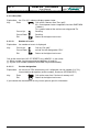
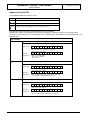
1.8.2 Tariff rate calendar
DataFW4 features four independent, hierarchically structured tariff rate calendars with up to 4
energy and maximum tariff rates each and a common public holiday table for 50 public
holidays. Each register (input register or summation register) can be assigned to any tariff rate
calendar which then determines its tariff rate structure.
A tariff rate calendar is structured with 3 hierarchical levels:
• seasonal programs (up to 6)
• weekly programs (up to 8 tariff types)
• daily tariff programs (up to 15 daily programs with 16 switching times each)
The tariff rate calendar must only be parameterized via the parameterization software
DMFPARA. Please consult the manual for the parameterization software for the procedure to
follow.
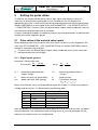
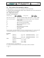
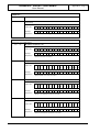
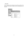
Seasonal programs: For setting the seasons (and other time periods with special tariffs or
other special requirements) select the "Season" field in the "Tariff calendar" menu item.
Season
Begin
1
MM-DD 00:00
2
MM-DD 00:00
3
MM-DD 00:00
4
MM-DD 00:00
5
MM-DD 00:00
6
MM-DD 00:00
MM-DD 00:00 :=
Month - Day Time
Example:
04-01 00:00 1. April, 00:00 (=: 31. March, 24:00)
DataFW4 / DATAREG
Page 24
User Manual
Bär Industrie-Elektronik GmbH ⋅ Rathsbergstr. 23 ⋅ D-90411 Nürnberg ⋅ Phone 0911/970590 ⋅ Fax +49 911 9705950
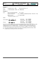
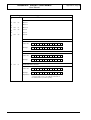
Weekly programs:
Season
1
2
3
4
5
6
Day of the week
Mo Tu-Th Fr
1
2
1
2
Sa
1
2
1
2
Su
1
2
FT 1
1
2
FT 2
1
2
FT 3
1
2
Daily tariff:
Example: Tariff rate for 4 energy and 2 demand tariffs:
Time
Tariff
from
to
Energy
Demand
00:00
06:00
ET1
DT1
06:00
10:00
ET2
DT2
10:00
12:00
ET3
DT2
12:00
13:00
ET4
DT2
13:00
16:00
ET3
DT2
16:00
22:00
ET2
DT2
22:00
00:00
ET1
DT1
Energy tariff:
4
3
2
1
00
02
04
06
08
10
12
14
16
18
20
22
00
02
04
06
08
10
12
14
16
18
20
22
00
Demand tariff:
4
3
2
1
00
DataFW4 / DATAREG
Page 25
User Manual
Bär Industrie-Elektronik GmbH ⋅ Rathsbergstr. 23 ⋅ D-90411 Nürnberg ⋅ Phone 0911/970590 ⋅ Fax +49 911 9705950
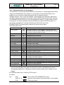
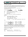
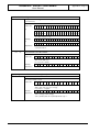
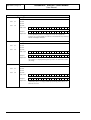
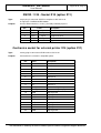
1.8.3 Tariff rate inputs
Tariff inputs TR1, TR2 and MRK determine the actual energy and demand tariffs insofar as this
is desired and provided in the customer specific hardware. Which inputs are used for setting
the tariffs and in which conditions these inputs correspond to which tariffs are all freely
programmable.
Default:
Mask energy
Mask demand
TR2
[X]
[X]
TR1
[X]
[X]
MRK
[ ]
[ ]
TR2
TR1
MRK
Energy Demand
0
0
0
ET1
DT1
0
1
0
ET2
DT2
1
0
0
ET3
DT3
1
1
0
ET4
DT4
Example: 4 energy and 2 demand tariffs (with TR1, TR2 and MRK):
Mask energy
Mask demand
TR2
[X]
[X]
TR1
[X]
[X]
MRK
[X]
[X]
TR2
0
0
0
0
1
1
1
1
TR1
0
0
1
1
0
0
1
1
MRK
0
1
0
1
0
1
0
1
Energy
ET1
ET1
ET2
ET2
ET3
ET3
ET4
ET4
Demand
DT1
DT2
DT1
DT2
DT1
DT2
DT1
DT2
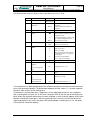
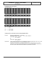
1.8.4 Tariff identifiers
If the tariff control via the tariff inputs is active, the tariff identifier consists of the status of inputs
TR1, TR2 and MRK. If the internal tariff calendar is active then the actual demand tariff will be
employed in place of the status of TR1 and TR2. Input MRK (measured value marker) is
always incorporated in the tariff identifier byte. This is printed out at the end of the measuring
period and stored on a diskette or on paper; remote interrogation is not possible.
1:
If the tariff rate inputs are active, the tariff identifier (base marking byte) is formed from
the state of the inputs TR1, TR2 and MRK. The base marking byte X is calculated as
follows in accordance with the assignment of the tariff rate control inputs:
X = (MRK) × 1+ (TR1) × 2 + (TR2) × 4
0:= input OFF; 1:= input ON
2:
If the internal tariff rate calendar is active, instead of the state of TR1 and TR2 the
current demand tariff rate (MT) of the tariff rate calendar is used. The input MRK
(measured value marking) is always placed in the base marking byte:
X = (MT - 1) × 2 + (MRK) × 1
3:
If the tariff combination is active, the external and the internal tariff rate calendar (see
points 1 and 2) are combined.
Page 26
DataFW4 / DATAREG
User Manual
Bär Industrie-Elektronik GmbH ⋅ Rathsbergstr. 23 ⋅ D-90411 Nürnberg ⋅ Phone 0911/970590 ⋅ Fax +49 911 9705950
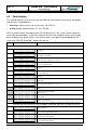
1.9
Measured value memory
1.9.1 Cyclic buffer
The measured value memory of the DataFW4 is subdivided into two buffer areas. These areas
are organized as cyclic buffers CB-01 (PP01) and CB-02 (PP02) and store the calculated
energy and demand values cyclically. Up to 16 values (input metered values and/or sums) can
be stored in each buffer. The assignment of the buffer is parameterized, i.e. during
parameterization the inputs or sums, summation balances that are to be stored in each buffer
are defined.
!
Only the first 32 inputs can be stored in the buffers!
!
If the number of input metered values or the sums are changed or the summation balance
calculation is reparameterized, the assignment of the cyclic buffer is affected.
The following applies:
•
Parameterization of the number of input metered values:
All input metered values are taken from the buffer assignment.
Parameterization of the number of summation registers or the summation balance
calculation:
All summation registers are taken from the buffer assignments.
• It is advisable to parameterize the number of input metered values and summation registers
before the buffer assignment.
•
1.9.2 Storage of the sums
The cyclic buffer of the DataFW4 can be assigned as follows:
!
Sum values
up to 8
Results of summation
balance calculation
up to 16 (8 for import, 8 for export)
The following is stored
the first 4 summation balances or all sums
Sequence in the buffer
(import: "+", export: "-")
sum1+, sum1-, sum2+, sum2-, sum3+, sum3-, sum4+, sum4-
While summation balance calculation is active it is not possible to store the results
of summation registers 5 to 8 in one of the two cyclic buffers.
DataFW4 / DATAREG
User Manual
Page 27
Bär Industrie-Elektronik GmbH ⋅ Rathsbergstr. 23 ⋅ D-90411 Nürnberg ⋅ Phone 0911/970590 ⋅ Fax +49 911 9705950
1.10 Pulse and signal outputs
DataFW4 can output summated pulses, tariff states and integration period synchronization
directly and locally. The signal outputs can be freely parameterized and are available in the
following technologies:
• Momentary pulse output, electronic (standard, IAW)
• Momentary pulse output, mechanical (option, IAWme.)
• Bipolar current pulse output (option, IAD).
DataFW4 has up to 8 parameterizable outputs. By parameterization any output can be routed
to any terminal and assigned any signal. Several outputs can be assigned to the same signal.
If this parameterized assignment is changed for one pulse output, the pulse buffer is cleared.
A pulse output can buffer up to 1000 pulses. As soon as this value is exceeded, the equipment
sets a fault bit in the device status. This fault bit has to be reset manually by the user on the
keypad.
The following signals can be output signals:
• Summated output signals 1 to 8 for import or export
• Integration period output MPA. The integration period output can also be wired from the
radio clock as an option.
• Tariff rate outputs TRF1 and TRF2
• Maximum reset RST
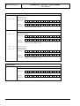
1.10.1 Tariff rate output
The tariff rate outputs TRF1 and TRF2 can be parameterized such that a defined output state
appears for each combination of energy and maximum demand tariff rates. After a RESTART
the following assignment applies:
Energy tariff
ET1 (AT1)
ET2 (AT2)
ET3 (AT3)
ET4 (AT4)
Output TRF2
0
0
1
1
Output TRF1
0
1
0
1
Example for "negated (inverted) TRF" (see DMFPARA):
Energy tariff
ET1 (AT1)
ET2 (AT2)
ET3 (AT3)
ET4 (AT4)
Output TRF2
1
1
0
0
Output TRF1
1
0
1
0
Page 28
DataFW4 / DATAREG
User Manual
Bär Industrie-Elektronik GmbH ⋅ Rathsbergstr. 23 ⋅ D-90411 Nürnberg ⋅ Phone 0911/970590 ⋅ Fax +49 911 9705950
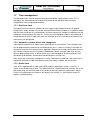
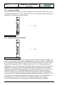
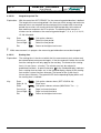
2
Module Description
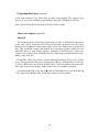
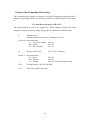
Figure 3, DataFW4 with 40 pulse inputs, MemoryCard unit, modem, radio clock and power supply unit
Depending on the device specifications, a DataFW4 device can consist of the following
components:
• CPU with keyboard, LCD display and RS232 (V.24) interface
• Main memory: MSC01 with MemoryCard (PC-Card) or DS01 unit or VU25/VU26 unit
• Modem, RS 232 interface or M-Bus interface
• Pulse inputs
• Pulse outputs
• Control inputs
• Control outputs
• Radio clock
• Power supply unit
• Centronics interface for external printer
• RS232 interface for load check
DataFW4 / DATAREG
User Manual
Page 29
Bär Industrie-Elektronik GmbH ⋅ Rathsbergstr. 23 ⋅ D-90411 Nürnberg ⋅ Phone 0911/970590 ⋅ Fax +49 911 9705950
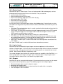
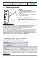
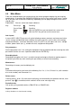
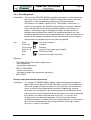
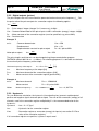
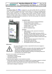
2.1
Keyboard with LCD display
1: LED A1 (red, blinking):
an error has occurred (warning)
1
2
3
12
2: LED A2 (red, blinking):
an error has occurred (critical error)
3: LED M (green, blinking):
measuring will soon begin
LED M (green, lit):
measuring is active
11
4
10
9
8
5
6
7
4: RS232 (V.24) service interface
5: ENTER:
Accepts an entry (exception: error inquiry)
6: Numbers:
For entering numeric values when setting
parameters.
Figure 4, Keyboard
7:
EXIT:
Leaves a menu item
Note:
If you press the EXIT key several times you will be returned to the permanent
display.
8:
Cursor : Pages through individual (next) menu items
Activate the main menu
9:
Cursor : Positions the cursor in numeric entry fields (to the right), or it is used for selecting
table values
10: Cursor : Positions the cursor in numeric entry fields (to the left), or it is used for selecting
table values
11: Cursor : Pages through individual (prior) menu items
12: Display:
2x16 characters
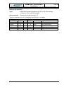
2.1.1 RS232 (V.24) service interface
Type:
25 pole SUB-D plug in compliance with ISO 2110, Connector pin
assignment V.24 / RS232/DIN 66020
Socket function:
Parameterization and read-out of the reset data through a PC.
The pin assignment of the V.24 socket on the CPU front panel is as follows:
Connection
Designation
Additional information
2
3
4
TxD
RxD
RTS
Input
Output
Input
5
6
7
20
CTS
DSR
GND
DTR
Output
Output
Input
Receive data
Transmit data
Connected to 5
Connected to 4
Operational
Signal ground
DEE Operational
DataFW4 / DATAREG
Page 30
User Manual
Bär Industrie-Elektronik GmbH ⋅ Rathsbergstr. 23 ⋅ D-90411 Nürnberg ⋅ Phone 0911/970590 ⋅ Fax +49 911 9705950
The service interface is used to program the DataFW4 unit with a fixed baud rate (9600 baud).
It is implemented as a 25 pin SUB-D connector (female) according to ISO2110, the pin
allocation is according to V.24/RS232C/DIN 66020.
Programming of the DataFW4 is done using the programming software DMFPARA. Please
read the user manual of the programming software DMFPARA for instructions on
programming.
For the connection between a DataFW4 and a PC, a programming cable or modem cable
(#6998) is required. Plug the programming cable into a free COM port of the PC/Laptop and
into the service interface of the DataFW4.
DataFW4 (25 pins)
Input/Output Pin No.
2
Input
—
3
Output
—
7
—
PC (25 pins) PC (9 pins)
Pin No.
Pin No.
Input/Output Standard usage
2
3
Output
TxD (transmit data)
3
2
Input
RxD (receive data)
7
5
GND (signal ground)
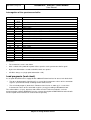
2.1.2 LED display on CPU
The three light emitting diodes on the left, next to the LCD display give information on the
following items:
• A1 (red, blinking)
an error has occurred (warning)
• A2 (red, blinking)
an error has occurred (critical error)
• M (green, blinking)
measuring will soon begin
• M (green, lit)
measuring is active
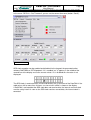
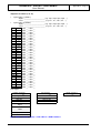
2.1.3 LCD Display
The LCD display gives the user system information and advice on how to proceed. The menucontrolled presentation shows you which program item you are in. For this purpose, the last
characters in the second display line are used as an information field to give the user help in
an abbreviated form.
The abbreviations have the following meaning:
Su, Mo, Tu, We, Th, Fr, Sa
Tm
I=
ET= ET (AT)
DT= DT, MAX (MT)
PP-n, P-n
PER. PUF. INP
PER. PUF. SUM
INFO
PARA, PROG
DELETE
MED
MD INP
MD SUM
Day of the week
measuring period (standard display)
Number of channels/inputs (standard display)
Energy tariff (standard display)
Maximum demand tariff (standard display)
Alarm (fault present)
Cyclic buffer (periodic buffer) n
Cyclic buffer (periodic buffer) input
Cyclic buffer (periodic buffer) summation
Information
Parameterization
Delete (clear) alarms
Medium
Maximum demands (input)
Maximum demands (summation)
DataFW4 / DATAREG
User Manual
Page 31
Bär Industrie-Elektronik GmbH ⋅ Rathsbergstr. 23 ⋅ D-90411 Nürnberg ⋅ Phone 0911/970590 ⋅ Fax +49 911 9705950
INP, I:
W: 1.000 Tm: 1.000
SUM+/-n, SU n, S+/-n
RST, R
T
BAUD, Bd
Inputs
Cos (ϕ) for integration time W (1..60 min) und Tm
Summation +/- n
Maximum demand reset
Tariff
Baud rate
2.1.4 LCD test
Call by pressing the ENTER-key in menu item: " MAINTENANCE → Display Test" .
2.1.5 Roll display
The ROLL display is called up under menu guidance. Before the button for the scrolling display
is used the scroll display menu must be programmed with addresses (refer to the operating
instructions on parameter setting). The contents of the address table must be in sequential
form. If the address table is not occupied but the scroll button has been primed then the display
will indicate: „Scroll display not occupied“.
The control input ANZ must have been activated during parameterization. If this is not the case
nothing will happen. There are two ways of calling up the individual menu items of the ROLL
main menu:
• Scrolling with the keys: Every time you press the "0" key or the ROLL (ANZ) input is
actuated the next menu item is shown on the display. If there are no further menu items, the
standard display is shown again. If the EXIT key is pressed in the ROLL menu, the menu is
exited and the standard display is shown again.
• Automatic scrolling in the main menu with set time interval: For automatic scrolling of
the ROLL display, the time must first have been set (in seconds) that each menu item is to
be visible in the LCD display using the parameterization program DMFPARA. After the set
time has elapsed the next menu item is called up. If the "0" key is pressed or the ANZ input
actuated during main menu display the time loop for the menu item is interrupted and the
next menu item is displayed. If you press the EXIT key the menu is exited and the standard
display shown again.
The scroll button can only be primed via the parameter setting program. If it has not been
primed then the display will indicate: „Scroll display not activated“.
If you happen to be in the menu structure then you can depress the scroll menu button to
abandon the display menu; the standard display briefly appears and then if the scrolling display
is activated (and occupied) the first menu item appears in the LCD display.
The menu structure of the ROLL display can include up to 50 menu items (see Appendix B).
The number and sequence of the menu items is defined during parameterization (see the
operating manual of the parameterization software DMFPARA).
Each menu item can be assigned a freely parameterizable text of up to 8 characters. If no text
is parameterized the display shows the register address bottom right providing the value output
leaves sufficient space for it.
If a text has been parameterized it is always displayed. This might cause characters of the
register value to be overwritten. Leading spaces in the text are ignored.
DataFW4 / DATAREG
Page 32
User Manual
Bär Industrie-Elektronik GmbH ⋅ Rathsbergstr. 23 ⋅ D-90411 Nürnberg ⋅ Phone 0911/970590 ⋅ Fax +49 911 9705950
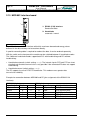
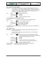
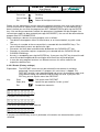
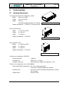
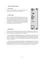
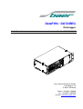
2.2
MemoryCard module MSC01
1
1: LED
Status indication of the
Memory Card
2
2: Slot for the Memory Card
3
3: Ejection button:
Only press if the green LED
is not lit
Figure 5, MemoryCard module MSC01
This plug-in module has a processor with 512 KB of RAM and 256 KB of ROM. In addition to
the two internal cyclic buffers it also features a slot for a memory card for PCMCIA/JEIDA
standard. A green LED on the front panel of the module indicates status and fault displays
module.
The MemCard unit MSC01 allows measured data (cyclic buffer: maximum demand values),
special occurrences (spontaneous buffer: such as e.g. power failure, change of parameter,
etc.) to be saved for a longer period of time in periodic buffers. In addition, the internally saved
data can be filed a second time on a SRAM memory card (PC card) to the PCMCIA/JEIDA
standard. The memory card can be read by any PC with standard commercially available
reading devices.
The reading software can be ordered separately!
DataFW4 / DATAREG
User Manual
Page 33
Bär Industrie-Elektronik GmbH ⋅ Rathsbergstr. 23 ⋅ D-90411 Nürnberg ⋅ Phone 0911/970590 ⋅ Fax +49 911 9705950
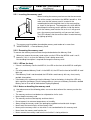
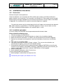
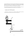
2.2.1 Inserting the memory card
When inserting the memory card ensure that the connector
side of the memory card enters the MSC01 board first. Also
make sure that the memory card is inserted in the
recording device with the guide slots in the same position
as shown in the figure 6. The two guide rails of the MSC01
board keep the memory card in position inside the device.
Push the memory card into the slot as far as it will go and
press the memory card carefully until you can feel it latch.
The LED indicates that the card has been inserted correctly
by lighting up briefly.
Figure 6, Inserting the memory card
!
The memory card should be formatted be memory card reader or in menu item
"MAINTENANCE → Format Memory Card".
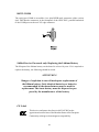
2.2.2 Removing the memory card
To remove the memory card, activate the eject button below the Memory Card.
!
When you remove the memory card, make sure the LED for the MSC01 card is not lit
because, if this is so, then the Memory Card is being accessed!
No recording interruption is required to change the memory card!
2.2.3 LED on the front
• If there is no Memory Card in the MSC 01, the LED on the front of the MSC 01 card lights
up.
• If a write-protected Memory Card is in the MSC 01, the LED on the front of the MSC 01 card
lights up.
• If the Memory Card is not formatted, the LED blinks continuously with very short, nearly
periodic interruptions.
• If the battery has not been put into the Memory Card or the battery is dead, the LED only
lights up when the Memory Card is being written on (same as a Memory Card with a loaded
battery, but an Error will be indicated on Display/Keyboard)
2.2.4 Notes on handling the memory card
!
•
•
•
•
•
•
•
•
•
Non-observance of the following points can cause destruction of the memory card or the
system!
The memory card must not be bent or subjected to similar strain.
Never drop the memory card.
The memory card must be kept dry and free of dust.
Do not expose it to extreme temperatures or humidity.
Always keep the memory card in the packaging supplied and avoid static charges.
Never touch the terminal pins of the memory card.
Never put the memory card in a slot which is not standardized for this memory card.
Never force the memory card into the slot.
Never remove the memory card from the unit while it is being written to.
Page 34
DataFW4 / DATAREG
User Manual
Bär Industrie-Elektronik GmbH ⋅ Rathsbergstr. 23 ⋅ D-90411 Nürnberg ⋅ Phone 0911/970590 ⋅ Fax +49 911 9705950
2.2.5 Battery supply
Since the SRAM inside the Memory Card is a volatile memory, it needs a battery power supply
so that data is not lost when the system's power supply is turned off. A special IC supervises
the supply voltage. It switches the card's internal SRAM supply line from the external supply
voltage to the built-in lithium battery as soon as the external voltage supply is switched off.
Through a special IC function, no data will be lost when the replaceable battery is removed. A
built-in capacitor is kept continuously charged during normal operation. As soon as the battery
is removed, the IC switches the capacitor voltage to the RAM supply lines which allows the
stored data to be maintained for a period of 5 minutes while the lithium battery is being
replaced.
Depending on the memory capacity of the card, the life of the battery ranges between six
months and five years if the card works in the data hold mode.
Life of a battery in the Panasonic Memory Card:
Memory Card capacity
Ambient temperature
25°C
40°C
64 kByte
5 years
3 years
128 kByte
5 years
2 years
256 kByte
4 years
1 year
512 kByte
2 years
6 months
1 MByte
1 year
3 months
To guarantee that saved data is secure, a minimum battery voltage of 2.65 V must be
maintained. At a battery voltage of <2.37 V, data will be secure but the battery should be
replaced as soon as possible.
2.2.6 Formatting the memory card
A memory card is formatted when the first 10 bytes are:
A5 5A
00
FF A5 5A
00
FF A5 5A
hexadecimal
A memory card is deemed to be erased when it is reformatted when:
44
41
54
41 2D 46
57
D7
hexadecimal
You can format and erase the memory card in the MSC01 board. The FORMAT function is
password-protected and can be called up via the keypad or the parameterization software
DMFPARA or in menu item "MAINTENANCE → Format Memory Card". The password must be
set during parameterization.
The memory card can also be formatted via one of the following memory card readers:
• MCM30,
• JA-232-A
• MSR10
Introduce the memory card into the reader, start the PC program MSC2DRA and activate the
FORMAT field.
If the memory card is formatted in the MSC01 board then the date, the time and the register
readings of the last integration period to have been completed are stored instead of the data
corresponding to the start identifier.
DataFW4 / DATAREG
Page 35
User Manual
Bär Industrie-Elektronik GmbH ⋅ Rathsbergstr. 23 ⋅ D-90411 Nürnberg ⋅ Phone 0911/970590 ⋅ Fax +49 911 9705950
2.2.7 Number of integration period entries
The basic values for the size of the internal measured value memory of the MSC01 are:
Number of bytes per integration period (NIP) are:
NIP = (no. values in CB01) ×
no. of decades in CB01
no. of decades in CB02
+ (no. values in CB02) ×
2
2
Number of integration period in internal measured value memory (NIPM) of the MSC01
are:
NIPM =
486000
NIP + 7
• The number of integration period entries that can be stored on the memory card depends on
the capacity of the memory card and the number of metering and summation registers. The
following basic values apply:
Number of integration period on the memory card (NIPMC):
NIPMC =
Size of the memory card (bytes) - 7362
NIP + 9
Examples:
Integration period Tm=15 min. and 4 decades per value:
MemoryCard
512 kByte
512 kByte
512 kByte
1 MByte
1 MByte
1 MByte
Values per integration
period
8
16
32
8
16
32
Number of integration
period
20600
12600
7000
41200
25200
14000
Days
Values per integration
period
8
16
32
Number of integration
period
21100
12400
6800
Days
214
131
72
428
262
144
Internal memory:
Internal memory
512 kByte RAM
512 kByte RAM
512 kByte RAM
218
129
70
Page 36
DataFW4 / DATAREG
User Manual
Bär Industrie-Elektronik GmbH ⋅ Rathsbergstr. 23 ⋅ D-90411 Nürnberg ⋅ Phone 0911/970590 ⋅ Fax +49 911 9705950
2.2.8 Writing to the memory card
If the memory card is deemed to be erased or all its parity checks are indicated as correct, the
device parameters, the content of the spontaneous buffer and the content of the cyclic buffers
are transferred. Multiple copying is possible.
The device parameters are used to identify records uniquely so that they can be correctly
assigned when they are read out again. The following device parameters are transferred to the
memory card from the main memory:
•
SCTM sub position number (5 digits)
•
Integration period duration
•
Assignment of the cyclic buffers CB-01 and CB-02
•
Software version of the MSC01 board
•
Radio clock reception active
•
Password check
•
Transmission rate of the serial interface
•
Number of minutes from 01.01.1980, 00:00 o'clock until the last time recorded as winter
time.
•
Number of minutes from 01.01.1980, 00:00 o'clock until the last time recorded as summer
time
•
Equipment status
•
Size of the cyclic buffer of the memory card in bytes
•
Size of the cyclic buffer of the memory card in integration periods
•
The last clock time received by the CPU (including date)
•
The clock time and date of the last integration period
•
Maximum demand values of the last integration period to have been completed for all
metered value inputs and summation registers
•
Energy values after the last integration period completed for all metered value inputs and
summation registers
•
Capacity of the memory card in integration period entries.
Spontaneous buffer:
The spontaneous buffer of the memory card is parameterized such that 100 entries can be
stored exactly like the main memory. However, assignment must always be free, i.e. 99 entries
can be stored.
If a new memory card is inserted, up to the last 89 entries are transferred to prevent the first
entry being overwritten again on storage because of the circulating buffer structure.
DataFW4 / DATAREG
Page 37
User Manual
Bär Industrie-Elektronik GmbH ⋅ Rathsbergstr. 23 ⋅ D-90411 Nürnberg ⋅ Phone 0911/970590 ⋅ Fax +49 911 9705950
2.3
Memory module DS01
Figure 7, Memory module DS01
This plug-in module has a processor with 512 KB of RAM and 256 KB of ROM with two internal
cyclic buffers (see MemoryCard module MSC01).
• The basic values for the size of the internal measured value memory of the DS01 are:
Number of bytes per integration period (NIP) are:
NIP = (no. values in CB01) ×
no. of decades in CB01
no. of decades in CB02
+ (no. values in CB02) ×
2
2
Number of integration period in internal measured value memory (NIPM) of the DS01
are:
NIPM =
486000
NIP + 7
Examples:
Integration period Tm=15 min. and 4 decades per value:
Internal memory
512 kByte RAM
512 kByte RAM
512 kByte RAM
Values per integration
period
8
16
32
Number of integration
period
21100
12400
6800
Days
218
129
70
DataFW4 / DATAREG
Page 38
User Manual
Bär Industrie-Elektronik GmbH ⋅ Rathsbergstr. 23 ⋅ D-90411 Nürnberg ⋅ Phone 0911/970590 ⋅ Fax +49 911 9705950
2.4
VU25 Unit
This board features a processor with 256 KB RAM and 128 KB ROM. VU25 does not have an
external memory medium. Instead the data memory can be read out locally via an RS232
(V.24) interface on the front panel
VU25 and VU26 are functionally identical. The only difference is the V.24 type of connector at
the front.
1: RS232 (V.24) interface
1
2: LED
Lit if RS232 interface active
2
3: Switchover between internal and
external RS232 (V.24) interface
- internal modem interface (off/aus)
- RS232 (V.24) interface (on/ein)
3
Figure 8, VU25 unit
Switchover between data readout via the interface module for data interrogation or the local
RS232 interface is performed manually with the switch on the front panel. The green LED on
the panel lights up if the RS 232 interface is active.
!
Please check the switch position after you have used the RS232 interface. Remote data
interrogation via the modem is not possible if the switch is in the "front" position!
Number of integration period entries
Examples:
Integration period Tm=15 min. and 4 decades per value:
Internal memory
256 kByte RAM
256 kByte RAM
256 kByte RAM
Values per integration
period
8
16
32
Number of integration
period
9100
5300
2900
Days
94
55
30
DataFW4 / DATAREG
User Manual
Page 39
Bär Industrie-Elektronik GmbH ⋅ Rathsbergstr. 23 ⋅ D-90411 Nürnberg ⋅ Phone 0911/970590 ⋅ Fax +49 911 9705950
RS232 (V.24) interface:
Type:
9 pole SUB-D plug in compliance with ISO 2110, Connector pin
assignment V.24 / RS232/DIN 66020
Socket function:
Read-out of the data through a PC.
The pin assignment of the V.24 socket on the VU25 unit is as follows:
VU25 (9 pins)
Input/Output
Input
Output
Output
Input
Pin No.
2
3
5
7
8
–––
–––
–––
–––
–––
PC (9 pins)
Pin No. Input/Output
3
Output
2
Input
5
8
Input
7
Output
Additional information
TxD (transmit data)
RxD (receive data)
GND (signal ground)
CTS (clear to send)
RTS (request to send)
DataFW4 / DATAREG
Page 40
User Manual
Bär Industrie-Elektronik GmbH ⋅ Rathsbergstr. 23 ⋅ D-90411 Nürnberg ⋅ Phone 0911/970590 ⋅ Fax +49 911 9705950
2.5
VU26 Unit
1
1: LED:
2
Lit if RS232 interface active
2: Switchover between internal and
external RS232 (V.24) interface
- internal modem interface (rear)
- RS232 (V.24) interface (front)
3
3: RS232 (V.24) interface
Figure 9, VU26 Unit
This board features a processor with 256 KB RAM and 128 KB ROM. VU26 does not have an
external memory medium. Instead the data memory can be read out locally via an RS232
(V.24) interface on the front panel
VU25 and VU26 are functionally identical. The only difference is the V.24 type of connector at
the front.
Interface Sub D female, 25 pins (Modem cable 1:1):
VU26 (25 pins)
Input/Output Pin No.
2
Input
3
Output
4
Input
5
Output
7
or
VU26 (25 pins)
Input/Output Pin No.
2
Input
3
Output
4
Input
5
Output
7
–––
–––
–––
–––
–––
PC (25 pins)
Pin No. Input/Output
2
Output
3
Input
4
Output
5
Input
7
Additional information
TxD
RxD
RTS
CTS
GND
–––
–––
–––
–––
–––
PC (9 pins)
Pin No. Input/Output
3
Output
2
Input
7
Output
8
Input
5
Additional information
TxD
RxD
RTS
CTS
GND
DataFW4 / DATAREG
User Manual
Page 41
Bär Industrie-Elektronik GmbH ⋅ Rathsbergstr. 23 ⋅ D-90411 Nürnberg ⋅ Phone 0911/970590 ⋅ Fax +49 911 9705950
Number of integration period entries
Examples:
Integration period Tm=15 min. and 4 decades per value:
Internal memory
256 kByte RAM
256 kByte RAM
256 kByte RAM
Values per integration
period
8
16
32
Number of integration
period
9100
5300
2900
Days
94
55
30
DataFW4 / DATAREG
Page 42
User Manual
Bär Industrie-Elektronik GmbH ⋅ Rathsbergstr. 23 ⋅ D-90411 Nürnberg ⋅ Phone 0911/970590 ⋅ Fax +49 911 9705950
2.6
Input and output boards
DataFW4 can be fitted with up to 6 input boards (type IEA08).
Each input board contains 8 identical inputs. The boards are available in a choice of different
technologies that can be combined.
• Pulse input S0 (IES)
• Pulse input momentary (IEW)
• Pulse input bi-polar (IED)
• Signal current inputs (analogue)
Inputs:
IES
Pulse input S0
S0 inputs are active inputs. They not only supply the pulse generator with a signal
voltage but also with an auxiliary voltage.
Only connect passive pulse generators!
S0 generators can contain their own electronics without needing to have their own
power supply unit. The limit currents and voltages are defined in the S0 specification
to DIN 43864. S0 inputs must be able to supply 10 mA at 800 Ω (to power the pulse
generator) and detect a current flow of 2.2 mA as "Off". They must not supply more
than 27 V. The maximum cable length is 0.5 m.
S0 inputs are therefore also suitable for simple volt-free contacts and passive optocoupler and transistor generators. They are also frequently used for control cables
(tariff rates, reset etc.).
IEW
Pulse input momentary
Momentary pulse inputs are supplied from the generator. The metering pulses are
transmitted directly as voltage pulses. In practice a wide variety of voltages and types
of current are used.
Momentary pulse inputs can be operated with DC or AC voltages of 24 V up to 265 V
without modification. The maximum pulse frequency is 10 Hz, the current consumption
is under 10 mA.
Continuous current (pulse duration ∞) is permissible. IEW modules are therefore
suitable for control cables.
IED
Pulse input bipolar current
Bipolar current inputs are passive inputs, i.e. they are fed from the pulse generator
and are therefore volt-free. Bipolar current pulses are DC voltage pulses with
alternating polarity. Traversing the 0 V line counts a pulse. It is also possible to use a
constant DC voltage whose polarity changes for each metering pulse instead of DC
voltage pulses.
The voltage is usually 24 V but can vary from 19 V to 60 V. The input current of the
electronic bipolar current inputs is less than 2 mA at 24 V.
Because a metering pulse represents a polarity change in the input voltage, IED
modules generate a complete pulse of approx. 40 ms duration (20 ms pulse, 20 ms
interval) internally for each polarity change. This must be taken into account in the
maximum pulse frequency (< 25 Hz). On request, IED modules can also be supplied
with a pulse duration of 140 ms (90 ms pulse, 50 ms interval) that can then be used
DataFW4 / DATAREG
User Manual
Page 43
Bär Industrie-Elektronik GmbH ⋅ Rathsbergstr. 23 ⋅ D-90411 Nürnberg ⋅ Phone 0911/970590 ⋅ Fax +49 911 9705950
with a pulse frequency of up to a maximum of 7 Hz.
Bipolar current transmission lines are largely immune to noise and must be used for
long distances. Under certain ambient conditions (adjacent current carrying cable,
long distances), a screened cable of sufficiently large cross section must be used.
With pulse inputs of 40 ms pulses the duration of the pulse and the interval
must both be set to 10 ms by parameterization (using DMFPARA). Pulse
debouncing will not be able to detect these signals otherwise
IEI
Pulse input inductive
A resonant circuit is formed by the inductive pulse input in combination with the LC
circuit inside the meter. This is periodically damped by a vane wheel mounted on the
rotor spindle giving rise to the pulses. IEI modules are therefore active inputs and
energise the pulse generator in the meter. The signal generator must be potentialfree, i.e. it must be neither earthed nor connected to other voltage levels. Because the
resonant circuit is sensitive to connector cable inductance and capacitance as well as
external interference signals, a secure functioning can only be guaranteed for a
connector cable length of up to 30cm.
Outputs:
IAD
Bipolar current pulse output
DataFW4 bipolar current outputs (IAD) supply a constant DC voltage of ± 24 V. The
polarity changes on every metering pulse. The maximum permissible load is 30 mA.
Bipolar current outputs require an extra power supply unit in the equipment that is
generally used to power other bipolar current outputs in the same equipment.
Individual bipolar current output wires must therefore not be connected together (not
even via the equipment connected to them). The subsequent bipolar current inputs
must be potential-free.
IAW el. Momentary pulse output electronic (solid state)
Electronic momentary pulse outputs (IAW el: solid state) behave like relay contacts,
i.e. they can be loaded with any type of current up to a maximum value 265 V/100 mA.
They combine wear-free operation with a higher switching frequency and are therefore
ideal for high pulse frequencies.
They can activate S0 inputs directly.
IAW me. Momentary pulse output mechanical (Relay contact)
Mechanical relays (IAW me: relay contact) are at present the only practical way of
offering truly isolated switching contacts. For outputs with switchover contacts, too,
only mechanical variation are available at present. The maximum load is 100 mA.
Mercury-wetted relays are usually used for pulse transmission lines because only they
have the necessary service life (> 109 switching cycles) to ensure decades of
operation at 5 Hz.
DataFW4 / DATAREG
Page 44
User Manual
Bär Industrie-Elektronik GmbH ⋅ Rathsbergstr. 23 ⋅ D-90411 Nürnberg ⋅ Phone 0911/970590 ⋅ Fax +49 911 9705950
2.6.1 Input board IEA08
The pulse inputs convert the pulse shapes and signal levels of the input signals that are usual
in remote metering to the TTL level used by the CPUs. On the front panel of the input board, 8
yellow LED’s show the activity of the 8 inputs.
1
1:
LED
1:
LED
Figure 10, Input board IEA08
2.6.2 Analogue input board IF8120
1
Figure 11, Analogue input board IF8120
The signal current input board measures power in order to establish energy consumption. The
power is measured over short intervals, multiplied by the time and the result is summated. This
sum is equivalent to the energy consumed. If the sum exceeds a fixed limit value "W", a 90 ms
output pulse is triggered and "W" is subtracted from the sum. "W" is designated the pulse
weighting and is set such that at maximum demand a pulse frequency of 5 Hz is reached. The
demand is measured via an external transducer that converts the measured demand to an
injected current (selectable ranges: 0 to 20 mA, 4 to 20 mA or 0 to 50 mA). The resolution of
the measurement is 11 or 12 bits depending on the accuracy of the converter used (e.g.
AD 574). To calculate the energy from the demand, the demand has to be integrated over a
certain period. The integration is approximated by multiplication by finitely small intervals. The
time intervals must be minimised to keep the calculation error small. The IF8120 performs a
measurement every 100 µs. this results in an interval time of 800 µs for 8 channels.
An IF8120 input board can be used instead of an IEA08 input board (pin compatible).
DataFW4 / DATAREG
User Manual
Page 45
Bär Industrie-Elektronik GmbH ⋅ Rathsbergstr. 23 ⋅ D-90411 Nürnberg ⋅ Phone 0911/970590 ⋅ Fax +49 911 9705950
2.6.3 Control inputs
DataFW4 has up to 7 control inputs. These are implemented in S0 technology only and are
parameterized and activated via the service interface. They are used for:
• synchronization (SYN input),
• maximum demand reset (RSTX input),
• external call-up button (ANZ input) of the ROLL display,
• tariff control inputs (TR1, TR2),
• measured value marking (MRK),
• maximum demand inhibit (ABL).
Like the pulse inputs, the control inputs feature signal debouncing. All control inputs must be
activated via the keypad or the parameterization software DMFPARA, otherwise they have no
function.
•
•
•
•
•
SYN input: The synchronization input is used to synchronize the internal real-time clock via
external transmitters/clocks.
RSTX input: The maximum demand reset can be triggered manually via the RSTX control
input. The device triggers the reset approx. 200 ms after the change in the level at the
RSTX input if the reset disable is not active.
ANZ input: The ANZ input allows display scrolling via an external button.
TR1/TR2 inputs: The tariff rate control inputs permit control from an external source (e.g.
by a ripple control receiver). The internal and the external tariff rate control can be active
simultaneously. Their functions are coupled via an OR operation.
MRK input: The MRK input is used for measured value marking and for calculation of the
tariff ID byte.
ABL input: The ABL input is used to inhibit maximum demand measurement.
2.6.4 Logical inputs
DataFW4 can be connected with signal outputs of external equipment via the maximum
number of 4 logical inputs. In this way the user can log messages that are relevant for metered
value processing. In the spontaneous buffer, all incoming signals are stored with the channel
number, date and time. S0 inputs are generally used.
The number of logical inputs affects the maximum expansion capability of the DataFW4, i.e. a
device configuration consisting of 48 signal inputs, 7 control inputs, 8 signal outputs and 8
summation registers means there is no room for any logical inputs.
2.6.5 Outputs
DataFW4 has up to 8 parameterizable outputs. By parameterization any output can be routed
to any terminal and assigned any signal. The following signals can be output signals:
•
•
•
•
Summated output signals 1 to 8 for import or export
Integration period output MPA
The integration period output can also be wired from the radio clock as an option.
Tariff rate outputs TRA1 and TRA2
Page 46
DataFW4 / DATAREG
User Manual
Bär Industrie-Elektronik GmbH ⋅ Rathsbergstr. 23 ⋅ D-90411 Nürnberg ⋅ Phone 0911/970590 ⋅ Fax +49 911 9705950
2.7
Modem
See the modem manual for information
about the modem.
Figure 12, Modem
The integrated fully automatic slot-in analog modem functions according to the CCITT
recommendation V.21 and V.22bis in full duplex mode with transmission rates 300, 1200,
2400 or 9600 (LGM 28.8D1 only) baud and in half duplex mode with a transmission rate of
1200 baud (V.23: LGM 9600H1 only). Dedicated-line operation is also possible.
The modem is connected with the remote metering centre via a leased line or the telephone
network. Data interrogation is initiated by the centre.
Modem type:
•
LGM 9600H1 (300, 1200 or 2400 baud)
• LGM 28.8D1 (300, 1200, 2400, 4800 or 9600 baud)
The operating mode of the modem is set via DIL switches on
the top of the housing of the slot-in modem. To set the mode
unscrew the modem and remove it from the DataFW4 housing
while the equipment is switched off.
S1/S2
S3
Figure 13, Modem DIL switches
DataFW4 / DATAREG
Page 47
User Manual
Bär Industrie-Elektronik GmbH ⋅ Rathsbergstr. 23 ⋅ D-90411 Nürnberg ⋅ Phone 0911/970590 ⋅ Fax +49 911 9705950
Examples of DIL switch settings S1 to S3:
LGM9600H1: 1200 Baud, 7, E, 1 (half duplex, V.23)
S1
1
LGM9600H1 or LGM28.8D1: 2400 baud, 7, E, 1 (full duplex, V.22bis)
S2
2
3
4
5
6
7
8
9
10
ON
OFF
1
S3
2
3
4
ON
OFF
1
S1
2
3
4
5
6
1
S2
2
3
4
5
6
7
8
9
10
ON
OFF
1
3
4
ON
OFF
3
4
5
6
7
8
9 10
1
1
3
4
ON
OFF
S1
2
S3
2
1
2
3
4
5
6
2
3
4
5
6
2
3
4
5
6
OFF
ON
LGM9600H1 or LGM28.8D1: 300 baud, 7, E, 1 (full duplex, V.21)
S3
2
S2
2
ON
OFF
OFF
ON
LGM9600H1 or LGM28.8D1: 1200 baud, 7, E, 1 (full duplex, V.22bis)
S1
1
3
4
5
6
1
S2
2
3
4
5
6
7
8
9 10
ON
OFF
OFF
ON
LGM9600H1 or LGM28.8D1: 2400 baud, 8, E, 1 (full duplex, V.22bis)
1
S3
2
3
4
ON
OFF
1
OFF
ON
LGM28.8D1: 9600 baud, 7, E, 1 (full duplex, V.32)
for IEC 60870-Protokoll
S1
1
ON
OFF
S2
2
3
4
5
6
7
8
9
10
1
S3
2
ON
OFF
3
4
1
OFF
ON
S1
2
3
4
5
6
1
ON
OFF
S2
2
3
4
5
6
7
8
9 10
1
ON
OFF
S3
2
3
4
1
OFF
ON
Figure 14, Examples of DIL switches
Please refer to the modem manual supplied for further settings of the DIL switches S1 to S3
and for special modem functions.
Page 48
DataFW4 / DATAREG
User Manual
Bär Industrie-Elektronik GmbH ⋅ Rathsbergstr. 23 ⋅ D-90411 Nürnberg ⋅ Phone 0911/970590 ⋅ Fax +49 911 9705950
2.8
DCF77 radio clock
(Applies only in Germany)
See the radio clock manual for information
about the radio clock
Figure 15, Radio clock DCF77
The radio clock receives time signals from the DCF77 transmitter in Frankfurt (77,5kHz) and
then sets the internal time. The module is installed and the user-specific program entered in
the factory. The integration period output (MPA) can be switched directly by the radio clock as
an option. The wiring must be prepared in the factory.
During normal radio clock operation, summer time switchover is performed using the summer
time table. The unit first converts the time from the radio clock to winter time and then adds
one hour if it is summer time according to the table. This has 2 advantages:
• Greater reliability: Switchover in the unit is performed even if the radio clock does not
receive a time telegram at the time of switchover
• Greater flexibility: Switchover times are implemented that differ from those of the DCF77
transmitter.
On request it is possible to accept the summer time information from the radio clock. The
summer time table is then ignored. The summer time switchover is performed on the next full
hour after the summer time announcement from the DCF77 transmitter if no time telegrams are
received beforehand. As soon as the first telegram with summer time ID is detected switchover
is performed even if the equipment is switched off at this time.
However, the following exceptions apply where the table is still used:
• Hardware failure of the radio clock.
• The radio clock is deactivated.
Immediately after "RESTART" the radio clock is deactivated. If the time is then set with the
parameterization software DMFPARA, the equipment first uses the table as the basis for its
summer time calculation.
• Parameterization of the time.
If the time is parameterized whilst the radio clock has not yet been synchronized (marking
"#" in the display), it is still not known at this time whether summer or winter time applies.
The table is therefore read.
See the radio clock manual for further information.
Radio clock reception can be enabled and disabled via the keypad, the parameterization
software DMFPARA or SCTM protocol. If it is enabled, an "F" appears in the middle of the
DataFW4 / DATAREG
User Manual
Page 49
Bär Industrie-Elektronik GmbH ⋅ Rathsbergstr. 23 ⋅ D-90411 Nürnberg ⋅ Phone 0911/970590 ⋅ Fax +49 911 9705950
second line of the display next to the current minute. If it is disabled this character is not
displayed.
The radio clock is read out once a minute and controls the system time of the DataFW4. If the
radio pulses fail for more than 24 hours, an alarm to this effect is shown on the display.
If DataFW4 is activated but the radio clock does not receive data, the internal real-time clock
must be set by hand. As soon as the radio clock receives correct data, the internal clock is
corrected.
Page 50
DataFW4 / DATAREG
User Manual
Bär Industrie-Elektronik GmbH ⋅ Rathsbergstr. 23 ⋅ D-90411 Nürnberg ⋅ Phone 0911/970590 ⋅ Fax +49 911 9705950
2.9
GPS satellite receiver clock
FAIL-LED:
on (red): receiver not synchronized
off: receiver synchronized, correct time received
(minimum one satellite can be received)
LOCK-LED:
on (green): correct GPS position (minimum four
satellites can be received)
COM 0: serial port (19200, 8N1), RS232connection to GPSMON32
BSL: pushbutton for firmware upgrade (don’t us it!)
See the GPS satellite receiver clock manual for
information about the GPS clock
Figure 16, GPS satellite receiver clock
The Global Positioning System (GPS) is a satellite-based radio-positioning, navigation and
time-transfer system. The GPS clock is using the "Standard Positioning Service" SPS.
Navigation messages coming in from the satellites are decoded by the GPS clock
microprocessor in order to track the GPS system time.
The GPS satellites are not geostationary: each of them circles around the earth approx. every
12 hours. The satellite signals can be received only if no building or any other object is in the
line-of-sight from the antenna to the satellite, therefore the antenna/converter unit must be
installed in a location with an unobstructed view of the sky. Very good reception is possible
when the antenna has a free view of 8° angular elevation above horizon.
The parameters for the GPS clock can be set up by GPSMON32 software (see
www.meinberg.de) via the serial port COM 0 (RS232 at the front of the GPS clock; use a cross
over cable). The port COM 1 is connected to the DataFW4 CPU1 (internal interface).
The correct parameter (see menu “Outputs – Serial Parameter) are:
•
COM 0: 19200, 8N1, Meinberg Standard, per second
•
COM 1: 9600, 7E2, Meinberg Standard, per second
Figure 17, GPS settings
DataFW4 / DATAREG
User Manual
Page 51
Bär Industrie-Elektronik GmbH ⋅ Rathsbergstr. 23 ⋅ D-90411 Nürnberg ⋅ Phone 0911/970590 ⋅ Fax +49 911 9705950
In the menu “GPS Init – Set Timezone” you can set the correct time zone (button “Send”):
Figure 18, GPS Timezone
GPS clock reception can be enabled and disabled via the keypad, the parameterization
software DMFPARA or SCTM protocol. If it is enabled, an "F" appears in the middle of the
second line of the display next to the current minute. If it is disabled this character is not
displayed.
The GPS clock is read out once a minute and controls the system time of the DataFW4. If the
radio pulses fail for more than 24 hours, an alarm to this effect is shown on the display.
If DataFW4 is activated but the GPS clock does not receive data, the internal real-time clock
must be set by hand. As soon as the GPS clock receives correct data, the internal clock is
corrected.
DataFW4 / DATAREG
Page 52
User Manual
Bär Industrie-Elektronik GmbH ⋅ Rathsbergstr. 23 ⋅ D-90411 Nürnberg ⋅ Phone 0911/970590 ⋅ Fax +49 911 9705950
2.10 MODA02 interface board
1
1: RS232 (V.24) interface
Read out of data
2: Handshake
automatic / normal
2
Figure 19, Moda02 interface board
The MODA02 has a RS232 interface with which maximum demand and energy values
buffered in the data memory can be read out directly.
A special connecting cable is required to read out the data. It can be ordered separately.
With the switch on the front panel the module can be switched between 2 handshake modes.
The 2 different handshake modes support both PCs with handshaking and PCs without
handshaking:
• Handshake automatic (switch setting: auto). The internal signals RTS and CTS are shortcircuited such that data transmission is only possible if the connected PC does not support
handshaking.
• Handshake normal (switch setting: norm)
The PC supports the usual RTS/CTS handshake. This mode ensures greater data
transmission reliability.
Example for connection between MODA02 and PC (pin assignment of the RS232/V.24
interface):
MODA02 (9 pins)
Input/Output
Pin No.
2
Input
3
Output
5
7
Output
8
Input
–––
–––
–––
–––
–––
PC (9 pins)
Pin No. Input/Output
3
Output
2
Input
5
8
Input
7
Output
Additional information
TxD (Transmit data)
RxD (Receive data)
GND (Signal-Ground)
CTS (Clear to send)
RTS (Request to send)
DataFW4 / DATAREG
User Manual
Page 53
Bär Industrie-Elektronik GmbH ⋅ Rathsbergstr. 23 ⋅ D-90411 Nürnberg ⋅ Phone 0911/970590 ⋅ Fax +49 911 9705950
2.11 M-Bus adapter board MBUS-DFW01
1
1: LED
Figure 20, M-Bus adapter board MBUS-DFW01
The M-Bus adapter board allows the DataFW4 to be connected to the M-Bus system. The MBus master permits connection of up to 250 devices consisting of any combination of DataFW4
and M-Bus devices. The data transmission protocol of the DataFW4 equipment can be the
SCTM format or the LSV1 procedure. The green LED on the front panel indicates that data is
being transmitted via the M-Bus when it lights up.
The M-Bus system is a powerful bus system for transmitting data. Central remote interrogation
of different equipment is possible with connection to this bus system. For further information
see the separate description of the M-Bus system.
Example of M-Bus configuration:
M-Bus
Datareg
Repeater
Datareg
e.g.
e.g.
Summation
box
Adapter
box
e.g.
6EA box
Figure 21, M-Bus system
Page 54
DataFW4 / DATAREG
User Manual
Bär Industrie-Elektronik GmbH ⋅ Rathsbergstr. 23 ⋅ D-90411 Nürnberg ⋅ Phone 0911/970590 ⋅ Fax +49 911 9705950
3
Installation and Commissioning
3.1
Scope on delivery
MemoryCard unit MSC01:
Does not have memory card inserted
Lithium batteries:
Inserted
Power supply:
Customer-specific
!
DataFW4 is not parameterized.
3.2
Default setting on restart
The table below shows the most important device parameters on a restart:
Device parameters
Defaults
Date
Thursday, 1st January 2004
Time
00:00:00
Equipment identifier (ID)
0000000000000000
Channel number
as ordered (none active)
Number of summation registers
as ordered
Summation balance
off
Operating mode
4 energy tariffs, 4 maximum demand tariffs
Pulse ratios
1:1 for all registers (energy and demand)
Register readings
not active; activation via DMFPARA or keypad
Summation registers
not active
Number of resets
0
Integration period duration
15 minutes
Starting time
none
Printer
active (if supplied)
Baud rate for SCTM
2400 baud
Cyclic buffers
not assigned
Pulse duration for inputs
at least 30 ms pulse length
at least 30 ms pulse interval
Output pulses
90 ms pulse length
110 ms pulse interval
Control inputs
not active
Summer time switchover
off
Tariff rate calendar
inactive
Radio clock
off
Password
12345
Language
English
DataFW4 / DATAREG
User Manual
Page 55
Bär Industrie-Elektronik GmbH ⋅ Rathsbergstr. 23 ⋅ D-90411 Nürnberg ⋅ Phone 0911/970590 ⋅ Fax +49 911 9705950
3.3
Installation of the device
3.3.1 Connection
Remove transport securing devices!
Check that batteries are inserted in the CPU and the main memory unit VU26 and that the
battery jumpers are set correctly. For instructions see Section 3.4. Data media are not inserted.
Before commissioning the equipment all the electrical connections must be made as described
in Appendix D or according to any special connection diagram(s) supplied.
!
For technical reasons only the meter data of the first 32 inputs can be stored in the demand
profile memories (cyclic buffers) in DataFW4 equipment. For this reason make sure that
meters required for billing purposes are routed to inputs 1 to 32.
3.3.2 Installation procedure
On initial startup, the DataFW4 must be parameterized with the basic data.
Please follow the following steps:
1.
2.
3.
4.
Remove transport securing devices.
Install the DataFW4 at the metering location as shown in the installation drawing.
Make the electrical connections as shown in the enclosed terminal connection diagram.
Remove any transport securing devices and insert the battery if necessary (see Section
3.4).
5. Now switch on the power supply.
6. Call up the menu item RESTART (Factory settings). This ensures that all buffers are
cleared and all registers reset to "0" or the default settings.
7. Parameterize the DataFW4 with the parameterization program DMFPARA via the Service
interface or the keypad as described in Section 4; (individually activate all the channels you
require using the parameterization software DMFPARA or via the keypad!).
8. Set the starting time.
9. Set the program protection switch (if necessary).
10. Exit the parameterization program.
11. Metering begins automatically at the preset time.
!
Activate the pulse inputs (see Section 4.4.2.15)!
Page 56
DataFW4 / DATAREG
User Manual
Bär Industrie-Elektronik GmbH ⋅ Rathsbergstr. 23 ⋅ D-90411 Nürnberg ⋅ Phone 0911/970590 ⋅ Fax +49 911 9705950
3.3.3 Transport and subsequent commissioning
It is possible to install a previously parameterized unit at a new measuring location without
having to reparameterize it.
The following procedure applies:
•
•
•
•
•
•
•
•
•
•
The previous data must be cleared:
Perform a RESTART with the aid of the parameterization program DMFPARA or via the
keypad. After this reparameterization is required.
The previous data must be retained:
Disconnect the terminals.
Transport the DataFW4 only in the specially designed packaging.
Install the DataFW4 at the new measuring location as shown in the installation diagram.
Make the connections as shown in the terminal connection diagram.
Remove the transport securing devices again.
Switch on the power supply.
The standard display appears on the display. In the lower line of the display the "FAULT
PRESENT: " character appears for power failure and the red LED A1 will blink at the
same time. Reset all alarms with the menu item "DELETE ERRORS" before starting
measurement.
If a starting time has not yet been set, set a new starting time.
Metering automatically begins at the preset time.
3.4
Battery replacement
The batteries of the DataFW4 must be inserted before startup! After startup the battery must
only be changed while the unit is switched on to prevent loss of data. Avoid touching live parts
inside the unit. The battery must not be held with metal tweezers or similar tools!
Order number for lithium battery:
Unit
Main unit CPU1,
VU26 unit
MemoryCard
Order no.
#5356 (BÄR-Type 2450)
see memory card
A lithium battery (#5356) has a life of approx. 10 years.
Description
Lithium battery LM2450 (plus pole
outside), CR2450 or CR2450N
Lithium battery for memory card
DataFW4 / DATAREG
User Manual
Page 57
Bär Industrie-Elektronik GmbH ⋅ Rathsbergstr. 23 ⋅ D-90411 Nürnberg ⋅ Phone 0911/970590 ⋅ Fax +49 911 9705950
3.4.1 Main unit CPU1
Unscrew the four screws of the keypad and remove the keypad from the DataFW4 (see Figure
22 and 23). Touch the metal frame of the unit briefly with your hand to equalize the potential.
After this remove the battery from the battery holder carefully and insert the new battery! Pay
attention to the position of the poles (the plus pole ⊕ must point away from the board)!
3.4.2 VU26 unit
Remove the two screws on the front panel of the VU26 (see Figure 23) and remove the front
panel of the VU26 carefully. Touch the metal frame of the unit briefly with your hand to
equalize the potential. You also have to unscrew the keypad to the right of the VU26. After this
remove the battery from the battery holder carefully. The new battery must now be placed in
the battery holder. Make sure the polarity of the battery is correct (the plus pole ⊕ must point
away from the board)!
1 2
3
1: Board
2: Battery holder
3: Live parts!
4: Connector
5: Red LED
6: Yellow LED
7: Program protection switch
45 6
7
Figure 22, Live parts! Caution when replacing the battery!
1
2
1
2
1: Battery holder
2: Battery
Figure 23, Battery holder with battery
3.4.3 MemoryCard
Because the SRAM in the memory card is a volatile memory, it requires a power supply so that
no data is lost when the system power supply is switched off.
For more information see the label on the MemoryCard.
DataFW4 / DATAREG
Page 58
User Manual
Bär Industrie-Elektronik GmbH ⋅ Rathsbergstr. 23 ⋅ D-90411 Nürnberg ⋅ Phone 0911/970590 ⋅ Fax +49 911 9705950
3.5
Program protection switch
Before transferring any parameters to the DataFW4 unit, the program protection switch must
be set to “Enable” (switch down). The program protection switch is located on the underside of
the display board of the DataFW4.
1
Battery holder
2
Red LED
3
Yellow LED
4
Program protection switch
5
EPROM
Figure 24, Program protection switch
!
Always touch first the grounded (earthed) metal frame of the unit with one hand to force
equalization of voltage potentials. Avoid any contact with other possibly charged parts of
the data logger unit when changing the setting of the program protection switch!
3.5.1 Open the main unit
To achieve access to this switch, the front panel of the main unit (CPU1) must be unscrewed
and take off. The program protection switch is located in the lower hand corner of the CPU1
and can be operated by hand.
3.5.2 Set the program protection switch
The meaning of the position is:
•
Switch down (enable): Setting of parameters is permitted, red LED is off.
•
Switch up (disable):
Setting of parameters is disabled, red LED is on
To refuse access to parameter settings to unauthorized persons, the front panel should be
sealed.
DataFW4 / DATAREG
User Manual
Page 59
Bär Industrie-Elektronik GmbH ⋅ Rathsbergstr. 23 ⋅ D-90411 Nürnberg ⋅ Phone 0911/970590 ⋅ Fax +49 911 9705950
4
Operation
Depending on the equipment ordered (varying software options or hardware components), the
following description may be too comprehensive.
4.1
Standard display
The LC display allows the user to call up status and system information such as buffer and
register contents. After turning on the equipment, the following text appears in the display (the
so-called permanent display)
Th 01.01.2004
00:00 Tm=15 K=08
Th 01.01.2004
00:00 ET=1 DT=1
or
Tm: Duration of measuring period in minutes
ET: Energy tariff
K:
DT: Maximum demand tariff
Number of channels set (inputs)
The first line displays the date as weekday, day, month and year.
In the second line, the left 5 places represent the time of day. In the 6th place, the character
„F“ - for radio-controlled clock (GPS) - may appear. The sign for „error present“ is in the 7th
place.
These are followed by the measuring period durations (Tm=) in minutes and the number of
Inputs set (I=) which alternate with the energy tariff (ET) and maximum (demand) tariff (DT)
presently in use. Between ET and DT, the character „M“ designates that maximum
measurement is in progress (but only when the measurement was previously started).
1
2
4
3
T h , 0 1 . 0 1 . 2 0 0 4 →1 3
0 0 : 0 0 F T m 1 5 M I = 0 8
5
1
6
7
2
8
9
10
4
3
T u. 01 . 06 .2 00 4
1 2 - 0 0 F E T = 1 M D T = 1
5
6
7
8
9
10
1
2
3
4
5
6
7
8
9
Day of the week
Winter time (,)
Date
Integration period status
current time/system time (:)
Radio clock rec eption
Fault present
Period length in minutes
Maximum demand measurement
active
10 Number of channels
1
2
3
4
5
6
7
8
9
Day of the week
Summer time (.)
Date
Integration period status
Start of measurement (-)
Radio clock rec eption
Fault present
Energy tariff
Maximum demand measurement
active
10 Maximum demand tariff
Page 60
DataFW4 / DATAREG
User Manual
Bär Industrie-Elektronik GmbH ⋅ Rathsbergstr. 23 ⋅ D-90411 Nürnberg ⋅ Phone 0911/970590 ⋅ Fax +49 911 9705950
The characters in the 6th place:
No radio clock (GPS), radio clock (GPS) not active
F
Radio clock (GPS) active
Radio clock (GPS) idling
!
Difference between radio clock (GPS) time and equipment time > 1 day, time is not
accepted
#
No internal synchronization
?
Error in radio clock telegram
DataFW4 / DATAREG
User Manual
Page 61
Bär Industrie-Elektronik GmbH ⋅ Rathsbergstr. 23 ⋅ D-90411 Nürnberg ⋅ Phone 0911/970590 ⋅ Fax +49 911 9705950
The following table shows the displays that are possible in the areas 1 to 10:
Area
Information
Display
1
Day of the week
Mo, Tu, We,
Th, Fr, Sa, Su
2
Summer time/
winter time
3
Date display
4
Integration period
status
.
,
without
6
Time or starting time
Radio clock
(GPS)
Summer time,
winter time
Summer/ winter time switchover
not active
DD.MM.YYYY Day. Month. Year
Starting time for measurement is set
→13
!12
5
Explanation
Minutes until the end of the current
integration period
Recording interruption, minutes until
the end of the integration period
without
Measurement not active
00:00
Current time/ system time
00-00
Start of measurement set
no display
F
no radio clock, radio clock not active
Radio clock active
Radio clock idling
!
Difference between radio clock time
and equipment time > 1 day, time is
not accepted
#
No internal synchronization
?
Error in radio clock telegram
7
Alarm
System error
8
Integration period
duration
Tm
Time in minutes (01 to 60)
or
ET
Energy tariff rates 1 to 4
current energy tariff
rate
9
ABL display
M
10
Number of channels
I
Maximum demand measurement
active
Number of active inputs
(channels: 01 to 48)
or
current maximum/
demand tariff rate
DT
Maximum demand tariff 1 to 4
If a starting time has been programmed, the selected starting time will alternate with the actual
time in the permanent display. To differentiate between the two, a dash (-) is used to separate
the hours from minutes in the starting time.
Furthermore, a stylized hour glass („egg-timer“) on the right edge of the first line symbolizes
that a starting time has been set. In this case, the green LED on the left side of the display will
blink. When the selected starting time has been reached, a small arrow will appear at the same
position instead of the hour glass, with the remaining time in minutes until the end of the this
measuring period. In this case, the green LED emitting diode is continuously lit (i.e. the green
LED at the left side of the display)
DataFW4 / DATAREG
Page 62
User Manual
Bär Industrie-Elektronik GmbH ⋅ Rathsbergstr. 23 ⋅ D-90411 Nürnberg ⋅ Phone 0911/970590 ⋅ Fax +49 911 9705950
Possible actions in the standard display:
Enter
ENTER
Shows errors
Cursor-Down
Main menu
Cursor-Right
Language selection
0-Taste
Cursor-Up
0
ROLL display
Main menu
DataFW4 / DATAREG
User Manual
Page 63
Bär Industrie-Elektronik GmbH ⋅ Rathsbergstr. 23 ⋅ D-90411 Nürnberg ⋅ Phone 0911/970590 ⋅ Fax +49 911 9705950
4.2
Menu structure
From the standard display you can branch to the various program displays by pressing key
combinations.
The following table explains the menu structure from the standard display. You return to the
standard display automatically or when you prematurely cancel a function (by pressing the
EXIT key several times).
Key
Enter
ENTER
Display
Explanation
Fault display
System fault
Memory fault
Program fault
Main menu
Cursor-Down
Info: inputs
Set parameter (parameterization): passwordprotected
Recording break (interruption): passwordprotected
Maintenance
Print
Delete errors (faults)
Periodic buffers
Register address
Cursor-Right
0-Taste
Cursor-Up
0
Language selection
The "CURSOR-RIGHT" key is used to select
the language menu directly. German, English,
French and Dutch are available. The default
setting is English
ROLL display
The "0" key simulates the external ROLL (ANZ)
control input and allows you to scan the ROLL
menu (ANZ must be parameterized and
activated)
Main menu
Register address
During programming, the individual values are entered via the numeric keys. These values are
saved with the ENTER key. Pressing the EXIT key quits a menu item without saving.
Exception:
Only integer divisors of 60 are allowed for the length of a measuring period. You
can search for the next larger or next smaller measuring period length with the
CURSOR-RIGHT and CURSOR-LEFT keys until the desired value appears in
the display. It will be accepted by pressing the ENTER key. The value set
appears in the standard display at „Tm=..“ The Baud rate is set in the same
manner.
DataFW4 / DATAREG
Page 64
User Manual
Bär Industrie-Elektronik GmbH ⋅ Rathsbergstr. 23 ⋅ D-90411 Nürnberg ⋅ Phone 0911/970590 ⋅ Fax +49 911 9705950
4.3
Fault display
This function displays all faults that have occurred and have not been reset yet on the display.
A distinction is made between:
•
Warnings: memory faults and system faults (W, LED A1)
•
Critical errors: hardware errors (F / CE, LED A2)
LEDs A1 and A2 on the front panel of the CPU display faults in the system. Alarms generally
have to be acknowledged, i.e. the LEDs continue to flash even though the faults have already
been remedied (e.g. power failure). Only after all alarms have been acknowledged with the
menu item "DELETE ERRORS", do the LEDs go out.
Class
Display
Explanation
System faults: The following system and printer faults can be displayed:
W
Power
fa ilur e
INFO;
!
Clear alarm!
W
Power fa ilur e
in curre nt T m
Power failure during recording. The current measuring period is marked
Display/ Keyb oard
no input !
Defective or no display/keypad on the CPU.
W
No Data from
DCF Radi o Cl ock
The radio clock has not sent the time to the CPU for 24 hours.
Check reception/antenna!
W
Printer
The protocol printer has failed.
Check!
W
Printer: No
W
accordingly; Clear alarm!
fail ure
p aper
Check connection, replace if necessary!
Printer paper finished.
Insert new paper roll!
W
Printer:
Buffer O verf low
Overflow in the internal printer buffer.
Data loss!
W
SYNC:
Out of
Synchronization signal outside the permitted range.
Check time!
W
F / CE
F / CE
F / CE
F / CE
CALEC:
No data
w indo w
!
No data from CALEC.
Check connection, replace if necessary!
!
EPROM-Ch ecks um
wrong !
RAM
¦
CPU EPROM defective.
Replace!
¦
Fault in the internal CPU RAM.
Replace CPU!
Erro r
FC/MSC E rror :
Communic atio n
!¦
FC/MSC E rror :
Hardware !
¦
Transmission error between CPU and RAM.
Check device!
Hardware fault in the memory-RAM.
Replace slot-in module!
Memory faults: Memory faults indicate faults in the RAM and communication module. On the
left-hand side of the first line the type of module is displayed and on the second line the fault.
W
W
FC01a
Medium
9 5%
FC01a
Medium
f ull
f ull
Diskette 95% full.
Replace diskette!
Diskette 100% full.
Replace diskette immediately! Data loss!
W
MSC01a
Battery
M em Card
empt y
MemCard battery flat.
Replace battery immediately!
W
MSC01a
Battery
M em Card
dama ged
MemCard supply switched over to stand-by battery.
Replace battery immediately!
DataFW4 / DATAREG
User Manual
Page 65
Bär Industrie-Elektronik GmbH ⋅ Rathsbergstr. 23 ⋅ D-90411 Nürnberg ⋅ Phone 0911/970590 ⋅ Fax +49 911 9705950
Class
Display
Explanation
W
MSC01a
M em Card
not form atte d
MemCard not formatted or not correctly inserted.
Format, check insertion, replace if necessary!
W
......
No Mediu m
No MemCard/diskette inserted.
Insert!
W
......
Write pr otec ted
MemCard is write-protected.
Deactivate write protection!
W
......
Wrong Fo rmat
MemCard not formatted or not correctly inserted.
Format, check insertion, replace if necessary!
W
......
Write Er ror
Error on writing the data to the MemCard.
MemCard defective, replace!
W
......
Read Err or
Error on reading data from the MemCard.
MemCard defective, replace!
F / CE
......
RAM/Time r
F / CE
F / CE
......
Hardware
......
Buffer
Er ror¦
Err or
¦
o verf low¦
RAM or timer defective.
Replace slot in module!
Hardware fault in the memory-RAM.
Replace slot-in module!
Overflow of the internal memory. Not all data were stored correctly.
Check and replace if necessary!
Puls faults:
W
Energy I np.
Overflow
xx
Energy register overflow for channel (input) xx
Check parameterization!
W
Energy S um
Overflow
xx
Energy register overflow for sum xx
Check parameterization!
W
MD Input
Owerflow
xx
Demand register overflow for channel (input) xx
Check parameterization!
W
MD Sum
Overflow
xx
Demand register overflow for sum xx
Check parameterization!
W
Pulse Ou tput
Overflow
xx
Pulse output overflow for output xx. The pulse output is displayed for which this
fault was set first.
Check parameterization!
4.3.1 Calling up the fault display
The starting point is the standard display. Press the ENTER key call up the "FAULT DISPLAY"
menu and the display switches over.
Explanation:
Key:
Fault display menu
Cursor-Up
Scroll through the fault display menu
Cursor-Down
Scroll through the fault display menu
Enter
Exit
Scroll through the fault display menu
Return to the initial display
4.3.2 LED display on CPU
LEDs A1 (warnings) and A2 (critical errors) on the front panel of the CPU displays faults in the
system. Alarms generally have to be acknowledged, i.e. the LEDs continue to flash even
though the faults have already been remedied (e.g. power failure). Only after all alarms have
been acknowledged with the menu item CLEAR ALARMS, do the LEDs go out.
DataFW4 / DATAREG
Page 66
User Manual
Bär Industrie-Elektronik GmbH ⋅ Rathsbergstr. 23 ⋅ D-90411 Nürnberg ⋅ Phone 0911/970590 ⋅ Fax +49 911 9705950
4.4
Main Menu
From the standard display you can branch to the various program displays by pressing key
combinations. If you press the CURSOR-DOWN key the first item of the main menu is called
up. If you press the CURSOR-DOWN key repeatedly you can page through the main menu
step by step.
Explanation: You can select from eight submenus
Key:
Cursor-Up
Scrolling
Cursor-Down
Scrolling
Enter
With the ENTER key you can branch to a menu item.
Exit
With the EXIT key you can exit the menu item.
Info: Inputs
In menu INFO: INPUTS you can call up the following memory contents and measured value
results: energy and demand meter readings for inputs and sums, pulse ratios of the energy
and demand meters, maximum demands, reset lists (RST lists) for inputs and sums, storage
medium, power factor (cos ϕ), number of resets, equipment designation.
Set parameters
Set the parameter: this is for setting the equipment's basic programmed after entering the valid
password! Confirm this max. 8 position code with the ENTER key.
Recording break
Recording interruption: this item is used to interrupt to change a diskette or replace paper in
the printer (possible only after entering the password), or to terminate recording
Maintenance
Formatting of memory card and display test
Print
Printed out: direct print out of one of the following lists: List 1, List 2, Reset List, (with selection
of a reset number) and Parameter List.
Delete errors
Clearing alarms: errors (list from the error display) are corrected by the operator and the „error
present“ sign () is cancelled, which switches off the error message relay.
Periodic buffer
Call up the cyclic (periodic) buffers (CB01/PP-01 or CB02/PP-02).
Register address
Call up all addresses from internal memory
DataFW4 / DATAREG
User Manual
Page 67
Bär Industrie-Elektronik GmbH ⋅ Rathsbergstr. 23 ⋅ D-90411 Nürnberg ⋅ Phone 0911/970590 ⋅ Fax +49 911 9705950
4.4.1 Information (Info: Inputs)
Explanation:
Key:
In menu INFO: INPUTS you can call up the following memory contents and
measured value results: energy and demand meter readings for inputs and
sums, pulse ratios of the energy and demand meters, maximum demands, reset
lists (RST lists) for inputs and sums, storage medium, power factor (cos ϕ),
number of resets, equipment designation.
Enter
Call up of the info menu
Cursor-Up
Scrolling
Cursor-Down
Scrolling
Exit
Return to the higher-level menu
The following applies for all submenus items:
Explanation:
Key:
Information on current (continuously updated) contents
The next higher input number
Enter
Cursor-Up
The next lower input number
Cursor-Down
The next higher input number
Exit
Leanes the submenu item
In submenu items, you can jump from lower or higher input numbers with the CURSOR-UP
and –DOWN keys.
4.4.1.1 Counter value
Explanation:
Key:
the menu COUNTER VALUE shows the following memory contents and
measured value results.
An active channel is marked in the second line with a „#“. Only activated
channels count pulses!
Enter
Call up of the counter value: demand meters, energy
cumulative (total), energy cumulative (tariff), energy meter
current (total), energy meter current (tariff)
Cursor-Up
Scrolling
Cursor-Down
Scrolling
Cursor-Right
in menu item tariff: scroll to the next tariff rate
Cursor-Left
in menu item tariff: scroll to the previous tariff rate
Exit
energy cumulative:
energy current:
Return to the higher-level menu
total amount of energy metered from day one up till now
energy consumed since the last reset
DataFW4 / DATAREG
Page 68
User Manual
Bär Industrie-Elektronik GmbH ⋅ Rathsbergstr. 23 ⋅ D-90411 Nürnberg ⋅ Phone 0911/970590 ⋅ Fax +49 911 9705950
4.4.1.2 Summation registers (SUM)
Explanation:
Key:
the menu SUMS displays the following memory contents and measured value
results.
Enter
Call up of the summation register: demand summation,
energy cumulative (total), energy cumulative (tariff), energy
meter current (total), energy meter current (tariff)
Cursor-Up
Scrolling
Cursor-Down
Scrolling
Cursor-Right
in menu item tariff: scroll to the next tariff rate
Cursor-Left
in menu item tariff: scroll to the previous tariff rate
Exit
energy cumulative:
energy current:
Return to the higher-level menu
total amount of energy metered from day one up till now
energy consumed since the last reset
4.4.1.3 Pulse ratio
Explanation:
Key:
the menu PULSE RATIO displays the numerator and denominator of the pulse
ratio of the energy and demand meters.
Enter
Call up the PULSE RATIO menu: demand meters, energy
meters
Cursor-Up
Scrolling
Cursor-Down
Scrolling
Exit
Return to the higher-level menu
4.4.1.4 Maximum demand (inputs/channels INP)
Explanation:
Key:
the MD MAXIMUMS INP submenu displays the maxima with date and time of
the demand meters for all tariff rates. The content is constantly up-dated.
Enter
Call up the submenu
Cursor-Up
Scrolling
Cursor-Down
Scrolling
Exit
Return to the higher-level menu
4.4.1.5 Maximum demand (summation register SUM)
Explanation:
Key:
the MD MAXIMUMS SUM submenu displays the maxima with date and time of
the summation register for all tariff rates. The content is constantly up-dated.
Enter
Call up the submenu
Cursor-Up
Scrolling
Cursor-Down
Scrolling
Exit
Return to the higher-level menu
DataFW4 / DATAREG
User Manual
Page 69
Bär Industrie-Elektronik GmbH ⋅ Rathsbergstr. 23 ⋅ D-90411 Nürnberg ⋅ Phone 0911/970590 ⋅ Fax +49 911 9705950
4.4.1.6 Reset list (inputs/channels INP)
Explanation:
Key:
the RST-LIST INP submenu displays the reset list of inputs (maxima with date
and time, energy cumulative, energy current).
Enter
Call up the submenu
Cursor-Up
Select the reset list (01-12)
Cursor-Down
Select the reset list (01-12)
Enter
Call up the reset list (01-12)
Cursor-Up
Select the list item: energy cumulative, energy current,
maximum demand, power factor
Cursor-Down
Select the list item: energy cumulative, energy current,
maximum demand, power factor
Enter
Call up the list item
Cursor-Up
Scrolling
Cursor-Down
Scrolling
Exit
Return to the higher-level menu
4.4.1.7 Reset list (summation register SUM)
Explanation:
Key:
the RST-LIST SUM submenu displays the reset list of summation register
(maxima with date and time, energy cumulative, energy current).
Enter
Call up the submenu
Cursor-Up
Select the reset list (01-12)
Cursor-Down
Select the reset list (01-12)
Enter
Call up the reset list (01-12)
Cursor-Up
Select the list item: energy cumulative, energy current,
maximum demand, power factor
Cursor-Down
Select the list item: energy cumulative, energy current,
maximum demand, power factor
Enter
Call up the list item
Cursor-Up
Scrolling
Cursor-Down
Scrolling
Exit
Return to the higher-level menu
4.4.1.8 Storage medium
Explanation:
Key:
If data media (diskettes or memory cards) are used, the free memory capacity
(%) is displayed.
Enter
Call up the submenu item
Exit
Return to the higher-level menu
If a diskette is full (00 % free), no more data are stored!
If a memory card is full it goes in the circulating buffer mode and the oldest entries are
overwritten!
DataFW4 / DATAREG
Page 70
User Manual
Bär Industrie-Elektronik GmbH ⋅ Rathsbergstr. 23 ⋅ D-90411 Nürnberg ⋅ Phone 0911/970590 ⋅ Fax +49 911 9705950
4.4.1.9 Cos (PHI)
Explanation:
Key:
the "Cos (hi)" submenu displays power factor.
Enter
Call up the submenu item "Cos (phi)":
W = current power factor: integration time from DMFPARA
(1-60min.)
Tm = power factor of the entire measuring period Tm
Cursor-Up
Scrolling
Cursor-Down
Scrolling
Exit
Return to the higher-level menu
4.4.1.10
Number of resets
Explanation:
the number of resets is displayed.
Key:
Cursor-Up
Call up "Cos (phi)"
Cursor-Down
call up "Version designation CPU"
Exit
Return to the higher-level menu
Call up the menu item: NO. OF RESETS xx/yy MM-DD -ss:mm (time)
xx: Reset number (can be parameterized between 01 and 12)
yy: System reset number (between 00 and 99, not parameterizable)
4.4.1.11
Version designation
Explanation:
the version of CPU and memory unit is displayed: version number (V.X.YY),
internal device designation (article number), checksum (EPROM: BCC)
Key:
Enter
Call up the menu item "Version of memory unit"
Exit
Return to the higher-level menu
If you contact the manufacturer for any reason, please give this information
DataFW4 / DATAREG
User Manual
Page 71
Bär Industrie-Elektronik GmbH ⋅ Rathsbergstr. 23 ⋅ D-90411 Nürnberg ⋅ Phone 0911/970590 ⋅ Fax +49 911 9705950
4.4.2 Parameterization via the keypad
The DataFW4 must only be parameterized while measurement is not being performed. Some
settings are disabled while measurement is running, others can be performed but cause
problems for the evaluation of data obtained during this integration period.
Complex functions such as tariff rate calendar, summer/winter time switchover, printer texts
and power factor can only be parameterized using the DMFPARA parameterization software.
The PARAMETERIZATION menu is password-protected. However, if no password has been
installed, you can skip the prompt for the password by pressing the ENTER key again. If a
password is installed and is entered incorrectly you return to the menu item
PARAMETERIZATION automatically and can call up the function again.
Parameterization menu:
Menu item
Restart system
Status Explanation
P
While measurement is not in progress: Restart causes all
parameters to be reset to the default setting (factory settings).
All memories and the clock are reset.
S
Printer mode
Setting the printer
S
Baud rate
Setting the transmission rate
S
Date
Setting the date
S
Time
Setting the actual time
S
Radio clock
Setting the radio clock
S
Summer time
Setting the summer time
S
SYNC input
Setting the SYNC input
S
Unit identifier
Setting the device identification
S
Station address
Setting the station address (DIN 19244)
P
Setting the number of channels
Number of inputs
P
Setting the number of summation registers
Number of sums
P
Setting the number of tariffs
Number of tariffs
P
Input quantization
Setting the "pulse ratio"
S
Counter value
Setting the initial values of the energy meters
P
Setting the "pulse ratio" for summation and the initial values of
Sums registers
the energy summation register
S
Max. resets
Setting the reset number
Periodic buffers (INP)
P
Configure the cyclic (periodic) buffers for inputs
Periodic buffers (SUM)
P
Configure the cyclic (periodic) buffers for summation registers
P
Setting the measuring period
Measuring period
P
Setting the starting time
Starting time
: cannot be changed while measurement is in progress. If you want to change these values,
you must end recording. A change of the other menu items is possible but may cause
considerable problems for subsequent evaluation software because the changes are not
flagged
P: Parameterization (only in Germany PTB-Version)
S: Setting
Key:
Enter
Digits (0 - 9)
Call up of the SET PARAMETERS menu
Input of the password for "parameterization" (up to 8 digits)
Enter
Confirm password
DataFW4 / DATAREG
Page 72
User Manual
Bär Industrie-Elektronik GmbH ⋅ Rathsbergstr. 23 ⋅ D-90411 Nürnberg ⋅ Phone 0911/970590 ⋅ Fax +49 911 9705950
Cursor-Up
Scrolling
Cursor-Down
Scrolling
Exit
Return to the higher-level menu
Before you are allowed entry into this part of the program, the user must enter a password. It
can be a maximum of 8 places and is confirmed with the ENTER key. If a password has not
been installed, you can enter the program item SET PARAMETERS by pressing the ENTER
key. If the correct password was entered, the parameters listed below can be changed. If an
incorrect password has been entered (message: INCORRECT), the user will be returned to the
program item SET PARAMETERS.
When selecting a submenu, the entry program runs as follows:
• The default value appears either as the old value, or an internal default, e.g. with a new
start.
• The entry of a number at the cursor position is executed with the NUMERIC keys. The
cursor automatically moves one place to the right.
• Characters that have been entered can be deleted with the CURSOR-LEFT key.
• Channels or summation registers respectively are selected with the CURSOR-UP and
CURSOR-DOWN keys.
• An entry is accepted by pressing the ENTER key. If you press the EXIT key instead, the old
value will not be changed and the next higher level menu item will be displayed.
• In case the entry program functions in a different manner, this will be stated in the
respective submenu item.
4.4.2.1 Restart (Factory settings)
Explanation:
Key:
The RESTART menu can only be selected if measurement is not being
performed. If measurement is in progress this menu item is skipped. The
RESTART function is password-protected and causes all parameters to be reset
to the default setting. All memories and the clock are reset. If you press the
EXIT key you can skip the menu item RESTART.
Enter
Digits (0-9)
Call up the menu RESTART
Input of the password for "restart system"
Exit
Do not clear memories
REST ART
ENTE R=Y
SYST EM ?
EX IT=N
If you press the ENTER key:
Rest art
Pass word
If the correct password has been entered:
Are you
ENTE R=Y
sure ?
EX IT=N
If you press the ENTER key: restart is performed, all memories are cleared and the system is
restarted.
DataFW4 / DATAREG
User Manual
Page 73
Bär Industrie-Elektronik GmbH ⋅ Rathsbergstr. 23 ⋅ D-90411 Nürnberg ⋅ Phone 0911/970590 ⋅ Fax +49 911 9705950
4.4.2.2 Printer mode
Explanation:
Key:
The PRINTER MODE submenu is used to set the printer. Printer settings are
shown in the second line of display. If no printer is installed the message "not
active" appears on the display
Enter
Call up the submenu
Cursor-Up
Scrolling
Cursor-Down
Scrolling
Exit
Return to the higher-level menu
PRINTER ON/OFF
PRINT VALUES
In the first submenu the printer is switched on or off.
Key 0
OFF: The printer is switched off and no further submenus will
be called.
Key 1
ON: The printer is switched on and four further submenus will
be called.
In this submenu you have two options (the printer must have been
activated first):
Key 1
All maximum demand average values (reading of individual
meter inputs at the end of each measuring period) and all
maximum demand summation registers will be printed at the
end of each measuring period (Display: PRINT VALUES (1)).
Key 0
Only the summation register readings will be printed (Display:
PRINT VALUES (0)), afterwards you are taken to submenu
PRINT LIST 1
LIST 1:
The time at which lists 1 and 2 and the reset list are printed is defined
via the keypad. The scope and content of the individual lists can be
parameterized with the parameterization software DMFPARA.
no list (print off): do not print
daily: at 00:00
monthly: on the first of each month at 00:00
Tm-End: at the end of each measuring period
Maximum Reset: after every successful reset
LIST 2:
see LIST 1
RST-LIST: see LIST 1
DataFW4 / DATAREG
Page 74
User Manual
Bär Industrie-Elektronik GmbH ⋅ Rathsbergstr. 23 ⋅ D-90411 Nürnberg ⋅ Phone 0911/970590 ⋅ Fax +49 911 9705950
4.4.2.3 Baud rate
Explanation:
Key:
The baud rate determines the transmission rate of the SCTM/LSV1/IEC60870 or
DIN19244 protocol in full duplex mode. The permissible baud rates are: 300,
600, 1200, 2400, 4800 and 9600.
Enter
Call up the submenu PER. BUFFER
(SCTM/LSV1/IEC60870)
Cursor-Right
Scrolling
Cursor-Left
Scrolling
Enter
Call up the submenu LOAD CONTROL (DIN19244-30sec
or IEC60870-1min) for load check
Exit
Return to the higher-level menu
You move to the next larger or next smaller Baud rate with the CURSOR-LEFT and CURSORRIGHT keys until you have the desired value. This is accepted by pressing the ENTER key. By
pressing the CURSOR-UP key, the old value that was set will appear.
The modem must be set to the same operating mode and baud rate (see Section 2.7 Modem)!
4.4.2.4 Date
Explanation:
Key:
Setting the date of the internal real-time clock. Here the current settings for the
day, month and year are displayed one after the other. Each of these can be
overwritten. You can exit the date setting with EXIT and the clock is set to the
previous setting
Enter
Call up the submenu
Exit
Return to the higher-level menu
Submenus: DAY (1-31), MONTH (1-12), YAER (1980-2400)
Normal input mode is used for this menu item. Submenu items are shown successively with
the current setting. This will be accepted by pressing the ENTER key.
A new date can be entered with the NUMERIC keys.
After you have pressed the ENTER key, a limit check will be executed and if necessary, you
may be requested to reenter the date.
If you press the EXIT key, the date in this submenu item will not be changed.
4.4.2.5 Time
Explanation:
Key:
Setting the actual time of day. The time is set in the sequence hours, minutes.
The seconds are automatically set to zero. If you cancel the entry prematurely
the time is reset to the previous value
Enter
Call up the submenu
Exit
Return to the higher-level menu
Submenus: HOURS, MINUTES
The device asks for the hours first, then the minutes. By pressing the ENTER key, the seconds
are set to 0.
Normal input mode is used for this menu item.
NOTE: If the equipment is equipped with a radio clock, this menu item does not have an
effect unless the radio-controlled clock malfunctions
DataFW4 / DATAREG
User Manual
Page 75
Bär Industrie-Elektronik GmbH ⋅ Rathsbergstr. 23 ⋅ D-90411 Nürnberg ⋅ Phone 0911/970590 ⋅ Fax +49 911 9705950
4.4.2.6 Radio clock (for Germany only) or GPS
Explanation:
Key:
This menu item activates and deactivates the radio clock or GPS scan of the
CPU
Enter
Key 1
Key 0
Call up the submenu
Activate: ON
Deactivate: OFF
Exit
Return to the higher-level menu
4.4.2.7 Summer time
Explanation:
Key:
This menu item activates and deactivates summer time (daylight saving time)
Enter
Key 1
Key 0
Call up the submenu
Activate: ON
Deactivate: OFF
Exit
Return to the higher-level menu
4.4.2.8 SYNC input
Explanation:
Key:
This menu item activates and deactivates the SYNC input (if radio clock is off)
Enter
Key 1
Key 0
Call up the submenu
Activate: ON
Deactivate: OFF
Exit
Return to the higher-level menu
4.4.2.9 Unit identifier (ID)
Explanation:
Key:
The unit identifier (equipment identification) is entered via this menu item
Enter
Digits (0-9)
Call up the submenu
Enter the 16 figure unit ID (identifier)
Exit
Return to the higher-level menu
4.4.2.10
Station address
Explanation:
Via this menu item you can enter the station address for the RS232 interface for
30 sec. (DIN19244) or 1 min. (IEC 60870) load check. The address"0"
deactivates the interface
Key:
Enter
Digits (0-9)
Call up the submenu
Enter the station address (1 - 255)
Exit
Return to the higher-level menu
4.4.2.11
Number of inputs
Explanation:
Via this menu item you can enter the maximum number of inputs (channels).
The channels must then be activated via the menu COUNTER VALUE (mark #).
While measurement is in progress this menu item is disabled because reducing
the number of channels also resets the cyclic buffers.
Key:
Enter
Digits (0-9)
Call up the submenu
Enter the number of channels (1 - 48)
Exit
Return to the higher-level menu
DataFW4 / DATAREG
Page 76
User Manual
Bär Industrie-Elektronik GmbH ⋅ Rathsbergstr. 23 ⋅ D-90411 Nürnberg ⋅ Phone 0911/970590 ⋅ Fax +49 911 9705950
4.4.2.12
Number of summation registers
Explanation:
With this menu item you can set the maximum number of active summation
registers. The summation registers must then be activated via the menu SUMS
REGISTERS. While measurement is in progress this menu item is disabled
because reducing the number of summation registers also simultaneously
resets the cyclic buffers. If the sum balance calculation is activated or
deactivated the buffer assignment is also reset.
Key:
Enter
Digits (0-9)
Call up the submenu
Enter the number of summation registers (0 - 8)
Exit
Return to the higher-level menu
4.4.2.13
Number of tariffs
Explanation:
Via this menu item you can set the maximum number of active energy and
demand tariff rates. The maximum number of tariff rates must not be exceeded
Key:
Enter
Digits (0-4)
Call up the submenu
Enter the number of tariffs (0 - 4)
Cursor-Up
Switch between energy and maximum tariff rates
Cursor-Down
Switch between energy and maximum tariff rates
Exit
Return to the higher-level menu
Submenus: Energy tariff, Maximum tariff
4.4.2.14
Input quantization
Explanation:
In the INPUT QUANTIZATION (pulse ratios) submenu you can set the
numerator and the denominator values for the energy and demand meters.
Some examples of this are calculated in "Section 5 Setting the pulse ratios".
Pulse ratios that are larger than 1:1 must be avoided because they impair the
resolution (conversion to "fast").
Key:
Enter
Call up the submenu
Cursor-Up
Switch between energy counter and MD counter
Cursor-Down
Switch between energy counter and MD counter
Exit
Return to the higher-level menu
• Pulse ratio MD counter
Explanation: Setting numerator and denominator values of pulse ratios for maximum
demand meters.
Key:
Enter
Call up the submenu MD COUNTER
Cursor-Up
Scrolling
Cursor-Down
Scrolling
Exit
Return to the higher-level menu
Normal input mode is used for this menu item.
The numerator value will be asked for first. After pressing the ENTER key, you must enter
the denominator value for the same input. If you only want to change the denominator value
of the pulse ratio, you must press the ENTER key when asked for the numerator which then
transfer you to the denominator value item.
With EXIT you will be returned to the submenu: Energy meter (pulse ratios). You can
quickly change the channel number with the CURSOR-UP and CURSOR-DOWN keys.
DataFW4 / DATAREG
User Manual
Page 77
Bär Industrie-Elektronik GmbH ⋅ Rathsbergstr. 23 ⋅ D-90411 Nürnberg ⋅ Phone 0911/970590 ⋅ Fax +49 911 9705950
• Pulse ratio energy counter
see "Pulse ratio MD counter"
Key:
Enter
Call up the submenu ENERGY COUNTER
Cursor-Up
Scrolling
Cursor-Down
Scrolling
Exit
Return to the higher-level menu
4.4.2.15
Counter value
Explanation:
The submenu METER READINGS is used to set the initial values of the energy
meters of a channel. At the same time the channel is activated. Activated
channels are marked with a "#".
Key:
Enter
Call up the submenu
Cursor-Up
Switch between total and tariff
Cursor-Down
Switch between total and tariff
Cursor-Right
Page between tariff rates (1 - 4)
Cursor-Left
Digits (0-9)
Page between tariff rates (1 - 4)
Enter the value (00000000 - 99999999)
Enter
If you confirm with the ENTER key, the energy meter is
assigned the value entered and summation is restarted. At
the same time the marking "#" appears
Exit
Return to the higher-level menu
Submenus: COUNTER VALUE TOTAL, COUNTER VALUE ENERGY TARIFF 1 – 4
The TOTAL meter corresponds to the sum of TARIFF meters (if n = 4). It is permissible to
enter 00000000 as a register status.
!
Activated channels are marked with a "#". Only activated channels (#) count pulses!
4.4.2.16
Summation registers
Explanation:
The submenu SUMS REGISTERS is used to select and set the initial values of
the summation registers. The submenu SUMS REGISTERS branches into
further submenus: SUM1 - SUM8
Key:
Enter
Call up the submenu
Cursor-Up
Scrolling (SUM1 – SUM8)
Cursor-Down
Scrolling (SUM1 – SUM8)
Enter
Call up the submenu (SUM nn)
Cursor-Up
Scrolling (INP. QUANTIZATION - COUNTER VALUE)
Cursor-Down
Scrolling (INP. QUANTIZATION - COUNTER VALUE)
Exit
Return to the higher-level menu
Page 78
DataFW4 / DATAREG
User Manual
Bär Industrie-Elektronik GmbH ⋅ Rathsbergstr. 23 ⋅ D-90411 Nürnberg ⋅ Phone 0911/970590 ⋅ Fax +49 911 9705950
The following settings are defined for each summation register (SUM1 - SUM8):
•
INP. QUANTIZATION: in the submenu you can set the numerator and the denominator
values for the energy and demand meters. The metering pulses of all inputs are weighted
and summated into 8 summation registers. Weighting can be selected in a range of 99999999 to 99999999. Negative weighting is only meaningful for summation balance
calculation. For simple summation, negative results are not entered in the result register.
After summation, the intermediate results are divided by a parameterizable common
denominator and entered in the energy or demand registers of the sums. The energy sums
can also be weighted with a separate denominator and routed to pulse outputs. On units
with sum balance calculation (hysteresis), the CURSOR LEFT and CURSOR RIGHT keys
are active under menu items MD-COUNTER and ENERGY COUNTER. With these keys it
is possible to change the sign.
Submenus:
– MD-COUNTER: numerator and denominator value
– ENERGY COUNTER: numerator and denominator value
– Σ-BUFFER: hysteresis
– PULSE OUTPUT: PULS RATIO 1/nnnnnnnn
•
Enter
Call up the submenu
Cursor-Up
Scrolling
Cursor-Down
Digits (0-9)
Scrolling
Enter the value (00000000+/- to 99999999+/-)
Cursor-Right
After the last figure: Change sign to minus (MD-COUNTER
and ENERGY
COUNTER)
Cursor-Left
After the last figure: Change sign to plus (MD-COUNTER
and ENERGY
COUNTER)
Exit
Return to the higher-level menu
COUNTER VALUE: the submenu is used to set the initial values of the energy meters
(total and tariff 1 to 4).
Submenus:
– INPUT SUMn TOTAL
– INPUT SUMn TARIFF (ET1 – ET4)
Enter
Call up the submenu
Cursor-Up
Switch between Total and Tariff rate
Cursor-Down
Digits (0-9)
Switch between Total and Tariff rate
Enter the value (00000000 to 99999999)
Cursor-Right
Switch between the tariff rates (ET1 – ET4)
Cursor-Left
Exit
Switch between the tariff rates (ET1 – ET4)
Return to the higher-level menu
DataFW4 / DATAREG
User Manual
Page 79
Bär Industrie-Elektronik GmbH ⋅ Rathsbergstr. 23 ⋅ D-90411 Nürnberg ⋅ Phone 0911/970590 ⋅ Fax +49 911 9705950
4.4.2.17
Maximum resets
Explanation:
the maximum reset number is setting with this function. The current reset is
assigned a number between 1 and 12 that is automatically incremented on each
reset in automatic mode until it reaches 12. Counting then begins at 1 again. In
this way, for example with a monthly reset, the current reset number
corresponds to the month and can be easily checked. The resets are triggered
via the external control input RSTX, the keypad or automatically, depending on
the options.
Key:
Enter
Digits (0-9)
Call up the submenu
Enter the reset number (1 - 12)
Exit
Return to the higher-level menu
4.4.2.18
Periodic buffers for inputs
Explanation:
the submenu PER. BUF. INP is used to configure the cyclic buffers and is not
active during measurement, i.e. entries can only be made before the set starting
time for measurement. After configuration all cyclic buffers are reset. In the
cyclic buffers, all demand values relevant to accounting are stored and can be
scanned via the modem interface (slot-in modem or modem interface board
MODA02). Up to 16 entries for the meter inputs and/or summation registers can
be stored in each buffer. The assignment is defined by assigning the value 1
(store: YES) or the value 0 (do not store: NO) to each input. If the total number
of inputs assigned to a buffer exceeds 16 the error message "<!x!>" is shown on
the display.
Key:
Enter
Call up the submenu
Cursor-Up
Scrolling
Cursor-Down
Digits (0 or 1)
Scrolling
1: YES or 2: NO
Exit
Return to the higher-level menu
Submenus: PB-01 and PB-02 for periodic buffer 1 and 2
!
If, after parameterization of the cyclic buffers, the number of channels or sums is reduced
or summation balance is activated or deactivated, the cyclic buffers are reset and must be
configured again!
4.4.2.19
Periodic buffers for summation register
Explanation:
the submenu PER. BUF. SUM: see "Periodic buffers for inputs"
Key:
Enter
Call up the submenu
Cursor-Up
Scrolling
Cursor-Down
Digits (0 or 1)
Scrolling
1: YES or 2: NO
Return to the higher-level menu
Exit
Submenus: PB-01 and PB-02 for periodic buffer 1 and 2
DataFW4 / DATAREG
Page 80
User Manual
Bär Industrie-Elektronik GmbH ⋅ Rathsbergstr. 23 ⋅ D-90411 Nürnberg ⋅ Phone 0911/970590 ⋅ Fax +49 911 9705950
4.4.2.20
Integration period Tm
Explanation:
With the menu item INT. PERIOD Tm, the measuring period duration is defined.
The length of the measuring period is the time over which energy and maximum
demand values are acquired and accumulated. At the end of each measuring
period, these values are transferred to the RAM and possibly to the external
data medium or output on the PC or printer. The following time intervals in
minutes can be selected as the measuring period length: 1, 2, 3, 4, 5, 6, 10, 12,
15, 20, 30 and 60.
Key:
!
Enter
Call up the submenu
Cursor-Left
Select the time period
Cursor-Right
Select the time period
Exit
Return to the higher-level menu
While measurement is in progress the measuring period duration cannot be changed!
4.4.2.21
Starting time
Explanation:
The starting time is the time at which the first measurement starts and can only
be entered before measurement begins. If the time entered is before the current
time the starting time will only apply to the next day. The format of the starting
time is hh-mm (hours - minutes). The minutes can only be selected in
(in the standard display) indicates
predefined time basis. A special character
that a starting time has been set. In the standard display, display of the starting
time and the system time then alternate. The format of the system time is
hh:mm (hours:minutes). The green M-LED for the operating display blinks until
the starting time is reached.
Key:
Enter
Digits (0 - 9)
Call up the submenu hours (SET HOUR 0..23)
Enter hours
Enter
Call up the submenu minutes (MIN.PLAN Tm← →)
Cursor-Left
Page in minute time base
Cursor-Right
Page in minute time base
Exit
Return to the higher-level menu
DataFW4 / DATAREG
User Manual
Page 81
Bär Industrie-Elektronik GmbH ⋅ Rathsbergstr. 23 ⋅ D-90411 Nürnberg ⋅ Phone 0911/970590 ⋅ Fax +49 911 9705950
4.4.3 Recording break
Explanation:
Key:
The menu item RECORD. BREAK (recording interruption) is called up from the
main menu. (Press the CURSOR DOWN key repeatedly until the menu item is
displayed.) It is password-protected and can only be activated while
measurement is in progress (green LED lit). The function is called up if it is
necessary to manipulate the DataFW4 with operations that require a defined
end or start identifier or that cannot be performed while measurement is in
progress. At the beginning of a recording interruption, the data of the last
complete measuring period are stored. The recording interruption must not
exceed the duration of one measuring period because no data are stored for the
duration of the recording interruption and the metered value and sum registers
are overwritten at the beginning of a new measuring period.
Enter
Call up the submenu
Cursor-Up
Scrolling
Cursor-Down
Digits (0 - 9)
Scrolling
Input of the password (up to 8 digits)
Enter
Confirm password
Exit
Return to the higher-level menu
Submenus:
•
STORAGE MEDIA: Data medium replacement:
- disk replacement
- printer paper replacement
•
END OF PROGRAM:
- end of measurement
- parameter change (Reassignment of the buffers)
•
MAX. RESET
Storage media (data medium replacement)
Explanation:
This function (STORAGE MEDIA) triggers a defined recording interruption of
approx. 200 ms (the green LED of the CPU begins to flash). An end identifier is
sent to the storage and communication unit or to the printer and all measured
values of the last measuring period to have been completed are stored or
printed out. All incoming pulses are counted, processed and buffered until the
end of the current measuring period. At the end of the current measuring period
these buffers are read out and cleared or reset to "0", i.e. up to this time
recording must have been activated again. For this reason the function
recording interruption is disabled if the measuring period only has one minute to
go or the last interruption occurred no longer than one minute ago. In both
cases this is shown in the display
DataFW4 / DATAREG
Page 82
User Manual
Bär Industrie-Elektronik GmbH ⋅ Rathsbergstr. 23 ⋅ D-90411 Nürnberg ⋅ Phone 0911/970590 ⋅ Fax +49 911 9705950
Key:
Enter
Digits (0 - 9)
Call up the submenu
Input of the password for "media change" (up to 8 digits)
Enter
Confirm password:
- possible (green LED blinking): "time for medium
replacement" is displayed → perform data medium
replacement
– disabled: "currently impossible" or "Media password
incorrect" is displayed
TIME FOR STARAGE MEDIA
Enter
The recording interruption is terminated immediately. All
measured values not yet stored are transferred to the RAM
and communication unit with the start identifier or output on
the printer (green LED lit permanently).
Return to the higher-level menu
Exit
If a power failure occurs during the recording interruption, the display returns to the initial
display after power recovery and indicates power failure ("!") and the green LED blinks. Call up
the menu item STORAGE MEDIA again. The display now shows the message "Continue
recording". Terminate the recording interruption as described above by pressing the ENTER
key. The green LED is now permanently lit.
End of program
Explanation:
Key:
This menu item terminates measured value recording. An end identifier is sent
to the RAM and communication unit or output on the printer and all inputs are
deactivated. The message "End of recording" is shown on the display briefly.
The green LED goes out.
Enter
Digits (0 - 9)
Call up the submenu
Input of the password for "parametrization" (up to 8 digits)
Enter
Confirm password
Exit
Return to the higher-level menu
Before restarting the program all inputs must be activated again (set "#" character).
Maximum resetting
Explanation:
Key:
The MAX. RESET function can be performed manually outside the normal
schedule in addition to the parameterized reset function if this has been enabled
during parameterization.
Enter
Digits (0 - 9)
Call up the submenu
Input of the password for "MD reset" (up to 8 digits)
Enter
Confirm password
Exit
Return to the higher-level menu
The reset frequency can also be set by parameterizing the reset disable. I.e. the reset can be
disabled temporarily.
DataFW4 / DATAREG
User Manual
Page 83
Bär Industrie-Elektronik GmbH ⋅ Rathsbergstr. 23 ⋅ D-90411 Nürnberg ⋅ Phone 0911/970590 ⋅ Fax +49 911 9705950
4.4.4 Maintenance
Explanation:
Key:
The submenu MAINTENANCE does not refer to general maintenance work on
the DATA FW but contains the option of formatting Memory Cards in the DATA
FW (password-protected) and display test. The memory card must not be writeprotected.
Enter
Call up the submenu
Cursor-Up
Scrolling
Cursor-Down
Digits (0 - 9)
Scrolling
Input of the password for "media change" (up to 8 digits) by
"Format MemoryCard" only
Enter
Confirm password
Exit
Return to the higher-level menu
Submenu: "Format MemoryCard" and "Display Test"
4.4.5 Printing
Explanation:
Key:
The submenu MAINTENANCE does not refer to general maintenance work on
the DATA FW but contains the option of formatting Memory Cards in the DATA
FW (password-protected) and display test. The memory card must not be writeprotected.
Enter
Call up the submenu
Cursor-Up
Scrolling
Cursor-Down
Digits (0 - 9)
Scrolling
Input of the password for "media change" (up to 8 digits) by
"Format MemoryCard" only
Enter
Confirm password
Exit
Return to the higher-level menu
Submenu: "Format MemoryCard" and "Display Test"
DataFW4 / DATAREG
Page 84
User Manual
Bär Industrie-Elektronik GmbH ⋅ Rathsbergstr. 23 ⋅ D-90411 Nürnberg ⋅ Phone 0911/970590 ⋅ Fax +49 911 9705950
4.4.6 Delete errors
Explanation:
Key:
The menu item DELETE ERRORS (clearing alarms) resets the fault status to
"0" and clears all alarms, if all faults have been remedied. If the system
interrogation is not confirmed, only those alarms are reset which refer to faults
which have been remedied (e.g. flashing LEDs after power failure). The fault
status is retained for faults that have not been remedied
Enter
Call up the menu reset faults: "Are all errors removed?"
Enter
All faults have been remedied. The alarm is cleared and the
alarm relay is reset (fault status "0")
Exit
Return to the higher-level menu
If not all faults have been remedied: the alarms of the remedied faults are cleared, the alarm
relay is not reset (fault status "1")
4.4.7 Periodic buffer shows
Explanation:
Key:
In menu PER. BUFFER you can call up the measured value results (load
profile) with the device status in the measuring period block (see Appendix A:
SCTM protocol).
Enter
Digits (0 - 9)
Call up the submenu
Input: YY for year
Enter
Digits (0 - 9)
Confirm
Input: MM for month
Enter
Digits (0 - 9)
Confirm
Input: DD for day
Enter
Digits (0 - 9)
Confirm
Input: HH for hours
Enter
Digits (0 - 9)
Confirm
Input: MM for minutes
Enter
Digits (1 - 2)
Confirm
Input: 1 or 2 for periodic buffer 01 or 02
Enter
Digits (0 - 9)
Confirm
Input: NN for entries in periodic buffer (01 - 16)
Enter
Confirm
Exit
Return to the higher-level menu
0 9- 0 1- 0 1
0 1
0 0 :0 0 p1
DataFW4 / DATAREG
User Manual
Page 85
Bär Industrie-Elektronik GmbH ⋅ Rathsbergstr. 23 ⋅ D-90411 Nürnberg ⋅ Phone 0911/970590 ⋅ Fax +49 911 9705950
4.4.8 Register address shows
Explanation:
Key:
Ente r
0000 0
In menu REGISTER ADDR you can call up the register addresses (see
Appendix B)
Enter
Digits (0 - 9)
Call up the submenu
Enter XXXXX for address
Enter
Confirm
Enter
Next address
Exit
Return to the higher-level menu
Ad dres s:
DataFW4 / DATAREG
Page 86
User Manual
Bär Industrie-Elektronik GmbH ⋅ Rathsbergstr. 23 ⋅ D-90411 Nürnberg ⋅ Phone 0911/970590 ⋅ Fax +49 911 9705950
4.5
Language selection
Explanation:
Key:
The DATA FW system display can be set to various languages. It is possible to
switch at any time. The default setting is English.
Cursor-Right
Call up the menu item "language selection" (from the
standard display)
Cursor-Up
Scroll through the language selection menu
Cursor-Down
Scroll through the language selection menu
Enter
Confirm: select the language
Exit
Possible languages:
• English
• German
• French
• Dutch/Flemish
• Polish
L angu age:
E ngli sh
Return to the higher-level menu
DataFW4 / DATAREG
User Manual
Page 87
Bär Industrie-Elektronik GmbH ⋅ Rathsbergstr. 23 ⋅ D-90411 Nürnberg ⋅ Phone 0911/970590 ⋅ Fax +49 911 9705950
5
Setting the pulse ratios
To calculate the energy and demand of various input signals with different scaling it is
necessary to normalize the incoming pulses to a standard unit. For this purpose the
appropriate pulse ratio is set for each input during parameterization with the parameterization
software DMFPARA or on the keypad (menu item PARAMETER → PULSE INPUT/OUTPUT
→ QUANTIZATION). The pulse ratios are determined by integral (whole-numbered) values for
the numerator and denominator with up to 8 digits.
Using the methods described in the following sections the average demand is established with
respect to the entire integration period.
5.1
Pulse ratios of the metered value inputs
Before beginning measuring, the pulse ratios of all inputs can be set (via the keyboard in the
menu item SET PARAMETER → INP. QUANTIZATION or via software DMFPARA). How to
proceed is explained using examples.
!
The pulse ratios are determined by integral (whole-numbered) values for the numerator
and denominator with up to 8 digits!
5.1.1 Digital inputs (pulses)
Numerator / Denominator ratio:
Demand (MD) :
Xp
W × 60
=
Yp R × Kp × Tm
Energy :
Xw
W
=
Yw R × Kw
X, Y
: Numerator and denominator,
integer, 8 digits
Tm
: Measuring period duration in
minutes
R
: Meter constant (e.g. pulses/kWh)
K
: Read constant
p, w
: power (demand), work (energy)
W
: Transformer constant
(Uprim/Usek x Iprim/Isek)
Because the demand values are displayed and stored with 4 digits, it is necessary to define a
suitable read constant Kp. It is determined by the following table:
Maximum demand (kW)
1
to 10
10
to 100
100
to 1000
1000
to 10000
10000
to 100000
100000 to 1000000
Read constant (K)
0,001 (=1/1000)
0,01 (=1/100)
0,1 (=1/10)
1
10
100
After multiplication of the displayed and stored demand value by the read constant, you obtain
the actual demand. The read constant for the energy values Kw must be preferably set to Kp.
However user-specific values are also permitted.
DataFW4 / DATAREG
Page 88
User Manual
Bär Industrie-Elektronik GmbH ⋅ Rathsbergstr. 23 ⋅ D-90411 Nürnberg ⋅ Phone 0911/970590 ⋅ Fax +49 911 9705950
Example 1:
exist:
Displayed value = 1503,
Read constant Kp = 10
follow:
Demand (MD) = 1503 × 10 = 15030 (kW)
Example 2:
exist:
Measuring period duration
Tm = 15 min,
Maximum demand
Pmax = 750 kW read constant Kp = 1/10 (Kw = 1/10)
Meter constant
R = 5 pulses/kWh
Transformer constant W = 1
follow:
Demand (MD) :
Xp
1× 60
8
=
=
Yp 5 × 1/10 × 15 1
Numerator
Energy :
Xw
1
2
=
=
Yw 5 × 1/10 1
Numerator
(Xp) 000008
Denominator (Yp) 000001
(Xw) 000002
Denominator (Yw) 000001
After this the meter readings are set using the parameterization software DMFPARA or on the
keypad (menu item SET PARAMETERS → COUNTER VALUE) and the pulse inputs are
activated! So that you can check activation, the character "#" appears in the INFO display.
!
The maximum demand or energy value shown in the display (menu item Info) is to be
multiplied by the reading constant (see Example 1).
DataFW4 / DATAREG
User Manual
Page 89
Bär Industrie-Elektronik GmbH ⋅ Rathsbergstr. 23 ⋅ D-90411 Nürnberg ⋅ Phone 0911/970590 ⋅ Fax +49 911 9705950
5.1.2 Signal current inputs
A continuous signal current flow is applied to the signal current inputs (e.g. 0 .. 20 mA, 4 .. 20
mA or 0 .. 50 mA). This current is proportional to the actual demand. By integration of the
current over time (i.e. the measuring period) it is possible to calculate the energy consumed,
from which the average demand is then calculated.
The analogue values are converted to pulses with fmax = 5 Hz inside the unit.
Numerator / Denominator ratio:
Demand (MD) :
Xp
DIFF
=
Yp Tm × 60 × 5 × Kp
Energy :
Xw
DIFF
=
Yw 3600 × 5 × Kw
X, Y
: Numerator and denominator, integer, 8 digits
DIFF
: Transducer range (max. valueencoder - min. valueencoder) := 5 Hz.
Tm
: Measuring period duration in minutes
K
: Read constant
The read constant is determined in an analogous way to the digital inputs.
Example 3:
exist:
4mA corresponds to 100 kW (:= min. value)
20mA corresponds to 750 kW (:= max. value)
DIFF = 750 kW - 100 kW = 650 kW
Measuring period duration
max. demand
Tm = 15 min
Pmax (DIFF) = 650 kW read constant Kp = 1/10 (Kw = 1/10)
follow:
Demand (MD) :
Xp
650
13
=
=
Yp 15 × 60 × 5 × 1/10 9
Numerator
Energy :
Xw
650
13
=
=
Yw 3600 × 5 × 1/10 36
Numerator
(Xp) 000013
Denominator (Yp) 000009
(Xw) 000013
Denominator (Yw) 000036
After this the meter readings are set using the parameterization software DMFPARA or on the
keypad (menu item SET PARAMETERS → COUNTER VALUE) and the pulse inputs are
activated! So that you can check activation, the character "#" appears in the INFO display.
A correction value must be added to the average demand value shown on the display. The
correction value is calculated as follows:
Correction value = Pmin = 100 kW
Example 4:
exist:
follow:
Displayed value = 0123,
read constant Kp = 1/10
Demand (after correction) = (123 × 1/10) +100 = 112,3 (kW)
DataFW4 / DATAREG
Page 90
User Manual
Bär Industrie-Elektronik GmbH ⋅ Rathsbergstr. 23 ⋅ D-90411 Nürnberg ⋅ Phone 0911/970590 ⋅ Fax +49 911 9705950
5.1.3 Customer-specific inputs (if heat meter)
The values of the customer-specific inputs (numerical inputs, e.g. heat calculator) are read in
directly from the serial interface. Conversion to demand and energy is performed automatically.
To improve the resolution you can correct the read constant.
Demand (MD) :
Xp 1
=
Yp Kp
Energy :
X, Y:
Numerator and denominator, integer, 8 digits
K:
Read constant
Xw
1
=
Yw Kw
Numerator and denominator, integer, 8 digits.
Example 5:
exist:
Max. demand: 55 kW
read constant Kp = 1/100 (Kw = 1/100)
follow:
Demand (MD) :
Xp
1
100
=
=
Yp 1/100
1
Numerator
Energy :
Xw
1
100
=
=
Yw 1/100
1
Numerator
(Xp) 000100
Denominator (Yp) 000001
(Xw) 000100
Denominator (Yw) 000001
After this the meter readings are set using the parameterization software DMFPARA or on the
keypad (menu item SET PARAMETERS → COUNTER VALUE) and the pulse inputs are
activated! So that you can check activation, the character "#" appears in the INFO display.
DataFW4 / DATAREG
Page 91
User Manual
Bär Industrie-Elektronik GmbH ⋅ Rathsbergstr. 23 ⋅ D-90411 Nürnberg ⋅ Phone 0911/970590 ⋅ Fax +49 911 9705950
5.2
Pulse ratios of the summation registers
All inputs going into a sum must first be reduced to a common denominator
!
The pulse ratios are determined by integral (whole-numbered) values for the numerator and
denominator with up to 8 digits!
5.2.1 Digital inputs (pulses)
Numerator / Denominator ratio:
Demand (sums) :
Xnps
W n × 60
=
Yps Rn × Kps × Tm
Energy (sums) :
Xnws
Wn
=
Yws Rn × Kws
Xnps, Xnws (sum. reg. s) :
Numerator (demand, energy), input number n - integer, 8 digits
Yps, Yws (sum. reg. s)
:
Common denominator of the pulse inputs used in summation,
integer, 8 digits
Wn
:
Transformer constant (for input number n)
Rn
:
Meter constant (e.g. pulses/kWh)
Tm
:
Measuring period duration in minutes
K
:
Read constant
p, w
:
power (demand), work (energy)
s
:
Summation register
n
:
Input number
If a pulse input is not to be included in a sum the associated numerator "Xn" must be set to "0".
The common denominator Y is the smallest common multiple of all denominators Yn!
Example 6:
exist:
follow:
Channel 1:
X1/Y1 = 3/2
Numerator for channel 1:
Y1 = 2
Channel 2:
X2/Y2 = 1/3
Numerator for channel 2:
Y2 = 3
Channel 3:
X3/Y3 = 2/5
Numerator for channel 3:
Y3 = 5
common denominator: Y = Y1 × Y2 × Y3 = 30
Channel 1:
X1/Y1 = 45/30
Channel 2:
X2/Y2 = 10/30
Channel 3:
X3/Y3 = 12/30
The read constant Ks is formed from Pmax.
Pmax is the sum of the demands PN of the "n" pulse inputs used for summation:
n
Pma x =
∑ P ⇒K
N
N =1
S
DataFW4 / DATAREG
Page 92
User Manual
Bär Industrie-Elektronik GmbH ⋅ Rathsbergstr. 23 ⋅ D-90411 Nürnberg ⋅ Phone 0911/970590 ⋅ Fax +49 911 9705950
5.2.2 Digital outputs (pulses)
The pulse output rate must not exceed the parameterized maximum pulse frequency fmax. For
the pulse ratio of the pulse output of a summation register the following applies:
Xa =
Yws
Rs × Kws
Xa
: Pulse output, integer (change YWS if necessary), 8 digits
Yws : Common denominator of the pulse inputs used in summation (energy), integer, 8 digits
Rs
: Meter constant of the summation register (must be specified, e.g. pulses/kWh)
Kws : Read constant
Example 7:
exist:
Common denominator
Yws = 250
Read constant
Kws = 10
Required meter constant for pulse output
Rs = 0,1 pulses/kWh
follow pulse output:
Xa =
250
1/10 × 10
Xa = 250
The pulse lengths and intervals can be changed using the parameterization program
DMFPARA (default 90/110 ms → t=200ms). For checking purposes it is advisable to calculate
the maximum pulse frequency at the output:
Maximum frequency at the output :
fmax = Pmax × Rs ×
1
[Hz]
3600
fmax
: Maximum frequency at the output [Hz]
Pmax
: Maximum demand of the summation registers [kW]
Rs
: Meter constant of the summation register [pulses/kWh]
Example 8:
exist:
follow:
Maximum demand
Pmax = 150000 kW
Meter constant
Rs = 0,1 pulses/kWh
Maximum frequency :
fmax = 150000 × 0.1 ×
1
3600
fmax = 4,1667 Hz
5.2.3 Hysteresis
For sum difference calculation, the hysteresis (free-wheeling Lws) prevents rapid output of
positive and negative signals onto one pulse output. The sum of the numerators (energy) of all
channels used in the summation register multiplied by 2 is the recommended value for the
hysteresis:
Hysteresis
: Lws = 2 × ΣXnws
Lws
: Hysteresis for the summation register
Xnws
: Summation register s: numerator (energy) for input n (see section 5.2 Pulse
ratios of the summation registers)
If all summation registers are positive, hysteresis equals zero!
DataFW4 / DATAREG
User Manual
Page 93
Bär Industrie-Elektronik GmbH ⋅ Rathsbergstr. 23 ⋅ D-90411 Nürnberg ⋅ Phone 0911/970590 ⋅ Fax +49 911 9705950
6
Technical Data
6.1
Housing dimensions
19" rack-mounted unit with 3 height units (3HE):
Width:
482.6 mm (84TE)
Height:
132.5 mm (3HE)
Depth:
270 mm
with 39-way edge connector: min. 330mm
Figure 25, DataFW4 19" rack-mounted unit
Degree of protection: IP 20 (IEC), IP 50 (with cover)
Panel mounted, large:
Width:
ca. 377 mm (63TE)
Height:
ca. 254 mm
Depth:
ca. 253 mm
Degree of protection: IP 53 (IEC)
Figure 26, DataFW4 panel mounted, large
Panel mounted, small:
Width:
ca. 250 mm (42TE)
Height:
ca. 254 mm
Depth:
ca. 253 mm
Degree of protection: IP 53 (IEC)
Figure 27, DataFW4 panel mounted, small
Limiting value according to VDE 0701:
Common ground:
≤ 300 mΩ
Insulation test:
Safety class II, ≥ 2 MΩ
Leakage current test:
with interference suppression capacitor ≤ 7 mA
Climatic stress (application class to DIN 40040):
Permissible ambient temperature: 0 to +40 °C (during operation)
-10 to +50 °C (during storage and transport)
Humidity stress:
max. 95 % relative humidity (during operation, storage
and transport)
Condensation:
not permissible
DataFW4 / DATAREG
Page 94
User Manual
Bär Industrie-Elektronik GmbH ⋅ Rathsbergstr. 23 ⋅ D-90411 Nürnberg ⋅ Phone 0911/970590 ⋅ Fax +49 911 9705950
6.2
Nominal voltage
Power supply:
For further information see the data sheet of the power supply unit!
Standard power supply unit:
HALTEC DSR 725S-5/15 A
Input voltage (230 VAC):
195-264 VAC
Input voltage (110 VAC):
95-132 VAC
Nominal frequency (50 Hz):
47-63 Hz
Power consumption (Voltage circuit):
< 70 Watt
Changing the auxiliary voltage (HALTEC DSR 725S-5/15 A) 230 VAC ↔ 110 VAC:
The unit can be set for operation with 110 VAC or 230 VAC by repositioning the line fuse.
Switching the auxiliary voltage in the DataFW4 is carried out by repositioning the fuse in
the power supply unit. All changes should be made whilst the equipment is disconnected
from the mains supply! To do this, DataFW4 power supply unit must be unscrewed (by
loosening the two screws on the front panel). The fuses are located on the bottom side of
the power supply unit.
!
When changing the auxiliary voltage, make sure that the proper fuse value (according
to sticker on power supply unit) is set!
DataFW4 / DATAREG
Page 95
User Manual
Bär Industrie-Elektronik GmbH ⋅ Rathsbergstr. 23 ⋅ D-90411 Nürnberg ⋅ Phone 0911/970590 ⋅ Fax +49 911 9705950
6.3
Inputs
Active
S0 pulse (IES) for inputs and control
signals:
Connect only passive switching generators
because the IES module supplies a
constant current.
Contact resistance:
R K ≤ 800Ω
!
Cable length:
≤ 10m
fmax:
5 Hz
RK
elektr.
V=12VDC
Figure 28, IES-Module
Pulse generator supply: 10 mA at 800 Ω,
V ≤ 27 V DC
Switching current:
I = 2.2 mA still "off"
V
Vmin:
24 VAC/DC (external)
Vmax:
265 VAC/DC (external)
Imax:
10 mA
fmax:
10 Hz
RK
elektr.
Momentary pulse (IEW):
Passive
Figure 29, IEW-Module
Passive
Bipolar current pulse (IED):
Vmin:
18 VDC
Vmax:
60 VDC
Imax:
5 mA
fmax:
20 Hz
Signal current input board IEAnalog:
A/D-Converter:
12 bit, not potentially isolated
Current:
0 to 20 mA, 4 to 20 mA, 0 to 50 mA
V
Figure 30, IED-Module
DataFW4 / DATAREG
Page 96
User Manual
Bär Industrie-Elektronik GmbH ⋅ Rathsbergstr. 23 ⋅ D-90411 Nürnberg ⋅ Phone 0911/970590 ⋅ Fax +49 911 9705950
6.4
Pulse / Signal outputs
Momentary output (IAW) "solid state – electronic switch"
(general) e.g. summation registers, control outputs:
Vmax:
265 VAC/DC
Imax:
100 mA
Figure 31, IAW-Output
IAW output is an electronic normally open
! The
contact (possible for IES).
Relay output "mechanical switch" (error relay, alarm ):
Vmax:
250 VAC/DC
Imax:
2A
Figure 32, Error relay
Radio clock relay output (MPA, Tariff; option):
Vmax:
220 VAC/DC
Imax:
2A
Figure 33, Radio clock relay
Radio clock optocoupler output (option):
Vmax:
70 VAC/DC
Imax:
20 mA
! Polarity important!
Kollector
Emitter
Figure 34, Optocoupler
DataFW4 / DATAREG
User Manual
Page 97
Bär Industrie-Elektronik GmbH ⋅ Rathsbergstr. 23 ⋅ D-90411 Nürnberg ⋅ Phone 0911/970590 ⋅ Fax +49 911 9705950
6.5
Accessories
Lithium battery:
Type:
2450 (e.g. LM2450, CR2450, CR2450N), plus pole outside
Permissible ambient temperature:
-20 to +60° C (during operation)
-40 to +60° C (during storage and transport)
Capacity:
500 mAh
Voltage:
3V
Min. voltage:
2,5 V
Life of the battery:
min. 10 years at 25° C
Self-discharge:
less then 1% in one year (25° C)
Max. current:
less then 5 µA (Typ. 1,5 µA, 25° C)
Order designations:
Unit
Main unit CPU1,
VU26 unit
MemoryCard
Order no.
#5356 (Baer-Type
2450)
see MemoryCard
Order designation
Lithium battery LM2450 (plus pole outside)
Alternative: CR2450, CR2450N
Lithium battery for MemoryCard
Baer Industrie-Elektronik GmbH
Rathsbergstr. 23
D-90411 Nürnberg
Phone: +49 (0)911 970590
Fax: +49 (0)911 9705950
Internet: www.baer-gmbh.com
SUBJECT TO CHANGE WITHOUT NOTICE!
Appendix A, Page 1
Appendix A
Communication Protocols
Appendix A, Page 2
DataFW4 / DLC32 / DATAREG
User Manual
The data stored in the equipment (device parameters, meter values, events such as power failure, parameter
changes, etc.) can be interrogated using the SCTM protocol, LSV1 procedure or IEC60870-102-5 protocol.
The interrogation is serial (7E1 or 8E1) with a settable baud rate (300, 600, 1200, 2400, 4800 or 9600 baud).
The data format of the interrogation protocol is defined during parameterization:
• 7E1: SCTM protocol or LSV1 procedure
• 8E1: IEC60870-5-102 protocol
After the RESTART, the unit is set to the SCTM protocol. You must select the required protocol before starting
measurement. However, it is still possible to switch between two protocols after the start of measurement.
SCTM protocol
The following sections describe the data format of the telegrams for communication with the SCTM protocol
(Serial Code TeleMetering).
Restrictions:
•
The first 5 digits of the unit ID are for the station number in the SCTM protocol (US number)
•
Point to point with 5 digits US number
•
Header length is 14 bytes (fix)
•
No command "To all"
•
Only one integration period (Tm1)
Following inquiry are possible:
•
Cyclic buffer 1 and 2 (PP01 and PP02)
•
Spontaneous buffer S51
•
Addresses 000-00 ... 999.99
DataFW4 / DLC32 / DATAREG
Appendix A, Page 3
User Manual
Device status in the measuring period block
The device status refers to the measuring period concerned and its data. It consists of 4 characters in ASCII
character format. To improve readability the assignment of the ASCII character to the bit combinations is the
same as for hexadecimal representation.
Hexadecimal → binary:
Hex
0
1
2
3
Binary
0000
0001
0010
0011
Hex
4
5
6
7
Binary
0100
0101
0110
0111
Hex
8
9
A
B
Binary
1000
1001
1010
1011
Hex
C
D
E
F
Binary
1100
1101
1110
1111
The device status of the measuring periods of the DataFW4 units is grouped together in 2 bytes of 2 ASCII
characters each:
st
1 byte
nd
1 ASCII character
2 ASCII character
T-bit U-bit M- A-bit S-bit
0
NP0
bit
bit
st
nd
2 byte
th
3 ASCII character
4 ASCII character
0
1
0
0
0
0
0
0
rd
Meaning of the bits:
Byte pos. Bit position
number number
Byte 1
Bit 7
Bit 6
Bit 5
Bit 4
Bit 3
Bit 2
Bit 1
Bit 0
Byte 2
Note:
Content
Explanation
T-bit
U-bit
Time setting, summer time switch over
Shortened measuring period because of time reset or power
failure
Parameters changed
Alarms
Sent during summer time
Not used
Entire measuring period without voltage
Not used
Number 40 in the binary system (hexadecimal representation)
M-bit
A-bit
S-bit
0
NP-bit
0
0100 0000
S-bit := 0 → Winter time (:= MEZ)
Example for device status in the measuring period block (byte 2 := 40 or 0100 0000):
Device
status
00 40
02 40
08 40
0A 40
10 40
20 40
50 40
→ Bits
0000 0000
0000 0010
0000 1000
0000 1010
Explanation
0100 0000
0100 0000
0100 0000
0100 0000
No fault, winter time
Entire measuring period without voltage (NP-bit=1), winter time
No fault, summer time (S-bit=1)
Summer time (S-bit=1), entire measuring period without voltage
(NP-bit=1)
0001 0000 0100 0000 Alarm (A-bit=1), winter time
0010 0000 0100 0000 Parameters changed (M-bit=1), winter time
0101 0000 0100 0000 Shortened measuring period (U-bit=1), alarm (A-bit=1), winter time
Appendix A, Page 4
DataFW4 / DLC32 / DATAREG
User Manual
Equipment status in the spontaneous buffer
The equipment status that is recorded in the spontaneous buffer represents the internal DataFW4 status. It
consists of 8 characters in ASCII character format and is stored in 4 equipment status bytes in the sequence 1,
2, 3, 4. The bit combinations also correspond to hexadecimal representation.:
st
nd
rd
th
1 byte
2 byte
3 byte
4 byte
st
nd
rd
th
th
th
th
th
1 char.
2 char.
3 char.
4 char.
5 char.
6 char.
7 char.
8 char.
0
0
0
B4 B3 B2 B1 B0 B7 B6 B5 B4 B3 B2 B1 B0 B7 B6 B5
0
0
B2 B1 B0 B7 B6 B4
B3
group information
Meaning:
st
1 byte
Bit 7
Bit 6
Bit 5
Bit 4
Bit 3
Bit 2
Bit 1
Bit 0
nd
2 byte Bit 7
Bit 6
Bit 5
Bit 4
Bit 3
Bit 2
Bit 1
Bit 0
rd
3 byte Bit 7
Bit 6
Bit 5
Bit 4
Bit 3
Bit 2
Bit 1
Bit 0
General status message
General status message
General status message
General status message
General status message
Not used
Not used
Not used
Radio clock (GPS) activated (0 = no/1 = yes)
Logical output 4 activated
Logical output 3 activated
Logical output 2 activated
Logical output 1 activated
MemCard: RAM/TIMER
Radio clock received no
data
Pulse output 4 overflow
Pulse output 3 overflow
Pulse output 2 overflow
Pulse output 1 overflow
Energy input (channel) or
sum overflow
Demand input (channel) or
sum overflow
MSC01 RAM or TIMER defective
No radio clock reception in the last 24 hours
MSC01: Hardware error
CALEC: No data!
SYN not in range
Printer buffer overflow
EPROM checksum
incorrect!
RAM fault
Pulse output – SUM4 - overflow
Pulse output – SUM3 - overflow
Pulse output – SUM2 - overflow
Pulse output – SUM1- overflow
Energy register overflow
Demand register overflow
MSC01 EPROM defective or rechargeable battery
fault
Heat meter not supplying data
Synchronization outside the permitted time range
Not used
Not used
Printer memory overflow
CPU EPROM defective
Fault in the internal CPU memory
DataFW4 / DLC32 / DATAREG
User Manual
th
4 byte
Bit 7
Bit 6
Bit 5
G
R
O
U
P
I
N
F
O
R
Bit 4
Bit 0..3 (0÷F)
0:
1:
2:
3:
4:
5:
6:
7:
8:
9:
M
A
T
I
O
N
SYSTEM: Power failure
occurred!
MEMORY: Communication
PRINTER: Printer has no
paper
PRINTER: Fault
DISK/MEMORY-FAULT
No fault
Read error
Write error
Medium 95 % full
Medium full
Write-protected
Wrong format
No data medium
Buffer overflow
MemCard on stand-by bat.
A:
B:
C:
MemCard battery flat
MemCard not formatted
Hardware fault
D:
E:
F:
RAM/timer fault
Hardware fault
General fault
Appendix A, Page 5
Power failure recorded
Serial link CPU data memory defective
End of paper reached
Parallel interface: printer defective
Fault on reading data from external medium
Fault on storing data to external medium
External data medium 95 % full
External data medium 100 % full
External data medium write-protected
Surface defect/not formatted
External data medium not inserted
Overflow of the internal memory
MemCard supply switched over to stand-by
battery
MemCard battery flat (replace!)
MemCard not properly inserted or formatted
MSC01 EPROM defective or rechargeable battery
failure
MSC01 RAM or TIMER defective
Hardware fault in RAM
General fault on external data medium
Example (see address 700-11 or spontaneous buffer 051-xx):
Status
00 00 00 00
10 00 00 00
10 00 00 80
00 00 00 07
15 00 00 00
0F 00 00 AB
Explanation
Radio clock activated
Radio clock activated, power failure recorded
External data medium not inserted
Radio clock activated, Logical outputs 1 and 4 activated
Logical outputs 1, 2, 3 and 4 activated, power failure recorded, end of paper reached,
MemCard not properly inserted or formatted
DataFW4 / DLC32 / DATAREG
Appendix A, Page 6
User Manual
Metered value status in the measuring period block
A 1-byte long metered value status is generated for each entry in cyclic buffers 1 or 2. Bit 6 is set (:= 1) in the
metered value status if a power failure occurs:
Byte 1
st
nd
1 character
2 character
0
Bit 6
0
0
0
0
0
0
Periodic buffer
Transmission of the meter values in the SCTM protocol. With the SCTM protocol, you can choose between 4
and 6 decades per meter value. This means that if you want to transmit 6 decades two zeros are added to the
4 decades because the demand values are calculated with 4 digits (fix).
The number of decades (4, 6 or 8) and the factor (multiplication by 1 or 100) is setting by DMFPARA.
Example: saved value: 1234 → outputting value (by SCTM standard): 123400 (by faktor = 100)
Values
1234
123456
1 2 3 4 5 6. 7 8
Number of decades
4
6
8
4
6
8
4
6
8
Default: decades = 1, factor = 100
Note: 6 or 8 digits are only by energy values possible!
Outputting values
Factor = 1
1234
0 0 1 2 3 4 Default:
00001234
3456
123456
00123456
5678
345678
12345678
Factor = 1 0 0
3400
123400
00123400
5600
345600
12345600
7800
567800
34567800
DataFW4 / DLC32 / DATAREG
Appendix A, Page 7
User Manual
Address list for SCTM
In the following table the markings mean:
Mark
Explanation
*
Table addresses can be set by remote parameterization!
The table values have 12 or 16 digits (for all software versions)
without
The table values have 16 digits (not on older software versions)
Simultaneous local and remote parameterization must be avoided!
Simultaneous local parameterization and remote interrogation is allowed as long as the communication
parameter such as baud rate, received disable time, send delay time, inactivity time-out and protocol type are
not changed!
Date and time
000
-00
Current date with time
Table value
Y
Y
M
M
D
D
W
H
H
m
m
Y Y = year, M M = month, D D = day,
W = day of week (1 = Monday, 7 = Sunday),
H H = hour, m m = minute
000
-01
Example:
9
4
0
1
0
1
Explanation:
Date: 01. January 1994,
Day of week: Saturday,
Time: 00:02
6
0
0
0
2
H
H
m
m
0
1
5
9
Winter/summer time switchover
Table value
Y
Y
M
M
D
D
Y Y = year, M M = month, D D = day,
H H = hour, m m = minute
000
-02
Example:
9
Explanation:
Date: 27. March 1994,Time: 01:59. Last time that was
received by the CPU marked as winter time
4
0
3
2
7
Summer/winter time switchover
Table value
Y
Y
M
M
D
D
H
H
m
m
0
2
5
9
Y Y = year, M M = month, D D = day,
H H = hour, m m = Minute
Example:
9
Explanation:
Date: 25. September 1994,Time: 02:59. Last time that
was received by the CPU marked as summer time
4
0
9
2
5
DataFW4 / DLC32 / DATAREG
Appendix A, Page 8
000
-03
User Manual
Winter/summer time flag
Table value
S
S = winter/summer time flag
0 = currently winter time
1 = currently summer time
Example:
Explanation:
010
-00
1
Summer time
Latest measuring period
Table value
Y
Y
M
M
D
D
h
h
m
m
0
2
1
5
YY = year, MM = month, DD = day,
hh = hour, mm = minute
Example:
9
4
0
9
2
5
Explanation:
Date: 25. September 1994,Time: 02:15.
Date and time of the latest measuring period to have
been completed
Status change
051
-xx
xx = Number of the spontaneous buffer entry
(cannot be directly interrogated, only contained in the spontaneous buffer)
Meter readings of the latest measuring period
100
-xx
Energy values tariff rate 1
100
-00
Meter 01
:
Meter xx
100
-31
Meter 32
100
-32
Sum 01
:
Sum xx
-39
Sum 08
100
Table value
A
A
A
A
A
A
A
A
5
3
0
8
6
4
AAAAAAAA = Meter reading
Example:
Explanation:
101
-xx
ditto for tariff 2
102
-xx
ditto for tariff 3
103
-xx
ditto for tariff 4
9
7
Meter readings of the latest measuring period of the
selected meter and tariff rate
DataFW4 / DLC32 / DATAREG
Appendix A, Page 9
User Manual
Meter readings of the latest measuring period
104
-xx
Demand values
104
-00
Meter 01
:
Meter xx
104
-31
Meter 32
104
-32
Sum 01
:
Sum xx
-39
Sum 08
104
if 6 decades were selected for MSC01 V 3.xx, V 4.xx, V 5.xx and Fc01 V 4.xx
Table value
0
0
L
L
L
L
9
8
7
6
LLLLLL = Demand values
Example:
0
0
if 6 decades were selected and MSC01 V 1.xx and Fc01 V 3.xx
Table value
L
L
L
L
0
0
9
8
7
6
0
0
L
L
L
L
9
8
7
6
LLLLLL = Demand values
Example:
104
-xx
if 4 decades were selected
Table value
LLLL = Demand values
Example:
Explanation:
The demand values always have 4 figures. If you
select 6 decades, 2 zeros are added to 4 decades of
the demand value (customer-specific).
DataFW4 / DLC32 / DATAREG
Appendix A, Page 10
User Manual
Data for load checking
105
-xx
30 s load check data
(optional)
105
-00
Measuring period identifier 0 to 9999
Table value
k
k
k
k
kkkk = measuring period identifier (x 30 seconds)
Example:
Explanation:
105
-01
Summation register 1
105
-02
Summation register 2
105
-03
Summation register 3
105
-04
Summation register 4
105
-05
0
0
1
Table value
s
s
s
s
Example:
0
0
2
1
Explanation:
0
1 x 30 seconds have elapsed since the beginning of
the measuring period.
21 pulses for summation register X have been counted
since the beginning of the measuring period.
Group value of measuring period identifier SUM1, SUM2, SUM3, SUM4
(20 characters)
Table value
k
k
k
k
S
1
S
1
S
1
S
1
S
2
S
2
S
2
S
2
S
3
S
3
S
3
S
3
S
4
S
4
S
4
S
4
0
0
0
0
0
0
0
0
0
0
k = measuring period identifier,
S1 to S4 = summation register 1 to 4
Example
0
Explanation:
In the first 2 X 30 seconds of the current measuring period 21 pulses were
counted for summation register 1.
0
0
2
0
0
2
1
0
0
DataFW4 / DLC32 / DATAREG
Appendix A, Page 11
User Manual
Data for load checking
105
-06
Group value measuring period identifier, inputs 1 to 32
(132 characters)
Table value
k
k
k
k
Z
1
Z
1
Z
1
Z
1
Z
2
Z
2
Z
2
Z
2
Z
3
Z
3
Z
3
Z
3
Z
4
Z
4
Z
4
Z
4
to
Z Z Z Z Z Z Z Z Z Z Z Z Z Z Z Z Z Z Z Z
28 28 28 28 29 29 29 29 30 30 30 30 31 31 31 31 32 32 32 32
k = measuring period identifier,
Z1 to Z32 = meters 1 to 32
Example
0
0
0
3
0
0
1
8
0
0
0
0
0
0
0
0
0
0
0
0
0
0
0
0
0
0
0
0
0
0
0
0
0
0
0
0
0
0
0
0
to
Explanation:
109
-00
In the first 3 x 30 seconds of the current measuring period 18 pulses were
counted for meter 1.
Last maximum reset: date and time
Table value
n
n
M
M
-
D
D
h
h
:
m
m
2
-
2
1
1
2
:
5
1
nn = reset number
MM = month, DD = day
hh = hour, mm = minute
Example:
Explanation:
0
1
0
st
The reset "1" was performed on February 21 at 12:51 o'clock..
Sign (assignment of the summation registers)
400
-xx
Input xx + 1
xx = 00 to 31: inputs 1 to 32
Table value
S8 S7 S6 S5 S4 S3 S2 S1 S8 S7 S6 S5 S4 S3 S2 S1
D D D D D D D D E E E E E E E E
S8D to S1D: sums 8 to 1 (D = demand),
S8E to S1E: sums 8 to 1 (E = energy),
0 = positive, 1 = negative
Example:
0
Explanation:
Input xx is added (negative) to
sum 1 (energy), sum 4 (energy),
sum 1 (demand) and sum 4 (demand) with the sign "-"..
0
0
0
1
0
0
1
0
0
0
0
1
0
0
1
DataFW4 / DLC32 / DATAREG
Appendix A, Page 12
User Manual
Sum balance
401
-00
Sum balance on / off
Table value
S
S = 0 - sum balance off,
S = 1 - sum balance on,
default = 0
Example:
Explanation:
1
Sum balance on
Last maximum reset (value and time)
41y
-xx
Maximum of MD values and time (y = 0 to 3)
y = 0 to 3: maximum demand tariff 1 to 4
xx = 00 to 31: inputs 1 to 32
xx = 64 to 71: sums 1 to 8 positive (e.g. import)
xx = 72 to 79: sums 1 to 8 negative (e.g. export)
Table value
M
M
M
M
M
M
.
D
D
h
h
:
m
m
0
8
:
1
5
MMMM = Maximum value and time (month.day
hour:min)
41y
-xx
Example:
9
Explanation:
Maximum value: 9876. date: 03. January, time: 08:15
8
7
6
0
1
.
0
3
Energy values by last maximum reset (y = 4 to 8)
y = 4: total energy value
y = 5 to 8: energy tariff 1 to 4
xx = 00 to 31: inputs 1 to 32
xx = 64 to 71: sums 1 to 8 positive (e.g. import)
xx = 72 to 79: sums 1 to 8 negative (e.g. export)
Table value
E
E
E
E
E
E
E
E
1
2
3
4
5
6
7
8
n
n
3
2
n
n
0
8
EEEEEEEE = Energy value
Example:
Explanation:
Energy value: 12345678, date: see address 109-00
Number of ...
600
-00
Inputs
Table value
nn = number of inputs
Example:
Explanation:
600
-01
The unit has 32 meter inputs.
Summation registers
Table value
nn = number of summation registers
Example:
DataFW4 / DLC32 / DATAREG
Appendix A, Page 13
User Manual
Number of ...
Explanation:
600
-02
The unit has 8 summation registers.
Energy tariff rates and maximum demand tariff rates
(tariff setting)
Table value
Example:
Explanation:
ET
DT
4
4
The unit is set for 4 energy tariff rates and 4 maximum demand tariff rates.
Activation states: inputs activated
(Character "#" in the INFO display)
601
-00
Bit pattern of inputs 01 to 08
Table value
E1 E2 E3 E4 E5 E6 E7 E8
Example:
Explanation:
601
-01
Example:
Explanation:
-02
0
0
0
0
0
E E
10 11
E
12
E
13
E
14
E E
15 16
0
1
0
0
0
0
E
17
E E
18 19
E
20
E
21
E
22
E E
23 24
0
0
1
0
0
0
1
0
Bit pattern of inputs 17 to 24
Example:
Explanation:
-03
E
9
0
Inputs 10 and 11 are active,
inputs 09 and 12 to 16 are not active
Table value
601
1
Bit pattern of inputs 09 to 16
Table value
601
1
Inputs 01 and 02 are active,
inputs 03 to 08 are not active
0
0
Input 20 is active,
Inputs 17 to 19 and 21 to 24 are not active
Bit pattern of inputs 25 to 32
Table value
Example:
Explanation:
E
25
E E
26 27
E
28
E
29
E
30
E E
31 32
0
0
0
0
1
0
Input 30 is active,
inputs 25 to 29 and 31 and 32 are not active
0
0
DataFW4 / DLC32 / DATAREG
Appendix A, Page 14
User Manual
Pulse matching (scaling)
602
-xx
Energy numerator
602
-01
Input 01
:
Input xx
602
-32
Input 32
Table value
Example:
Explanation:
603
603
603
-xx
-01
Input 01
Input xx
-32
Input 32
Example:
Explanation:
604
604
Z
Z
Z
Z
Z
Z
0
0
8
9
7
6
4
3
Energy denominator
:
-xx
0
Although you can select an 8-figure numerator with the new CPU, only the
6 least significant positions are displayed. The two most significant
positions are covered up with "0". However, all calculations are performed
with the full 8-figure numerator.
Table value
604
0
0
0
N
N
N
N
N
N
0
0
9
8
7
6
5
4
As for the numerator only the 6 least significant positions of the
denominator are displayed although all 8 positions are taken into account
(internally).
Demand numerator
-01
Input 01
:
Input xx
-32
Input 32
Table value
Example:
Explanation:
0
0
Z
Z
Z
Z
Z
Z
0
0
7
8
6
4
3
2
As with pulse matching with energy (numerator) only the 6 least
significant positions are displayed although (internally) all 8 positions are
taken into account.
DataFW4 / DLC32 / DATAREG
Appendix A, Page 15
User Manual
Pulse matching (scaling)
605
-xx
Demand denominator
605
-01
Input 01
:
Input xx
605
-32
Input 32
Table value
Example:
Explanation:
0
0
N
N
N
N
N
N
0
0
7
8
9
1
2
3
As with pulse matching for energy (denominator) only the 6 least
significant positions are displayed, although (internally) all 8 positions are
taken into account.
Pulse output matching (scaling)
607
-xx
Denominator for summation registers 01 to 08
607
-01
Summation register 01
:
Summation register xx
-08
Summation register 08
607
Table value
Example:
Explanation:
n
n
n
n
n
n
n
n
9
8
7
6
5
4
3
2
If the value is "0", the pulse output is disabled.
Assignment of the summation registers
61y
-xx
Energy summation registers (y = 1: sum1 to y = 8: sum8)
61y
-00
Common denominator
Table value
0
0
N
N
N
N
N
N
Example:
0
0
2
3
4
9
8
7
Explanation:
Only the 6 least significant positions are displayed although (internally) all
8 positions are taken into account.
DataFW4 / DLC32 / DATAREG
Appendix A, Page 16
User Manual
Assignment of the summation registers
61y
61y
-01
Numerator input 01
:
Numerator input xx
-32
Numerator input 32
Table value
0
0
Z
Z
Z
Z
Z
Z
Example:
0
0
0
0
0
0
0
2
Explanation:
62y
-xx
62y
-00
Demand summation registers (y = 1: sum1 to y = 8: sum8)
Common denominator
Table value
0
0
N
N
N
N
N
N
Example:
0
0
3
4
5
6
7
8
Explanation:
62y
62y
Only the 6 least significant positions are displayed although (internally) all
8 positions are taken into account.
Only the 6 least significant positions are displayed although (internally) all
8 positions are taken into account.
-01
Numerator input 01
:
Numerator input xx
-32
Numerator input 32
Table value
0
0
Z
Z
Z
Z
Z
Z
Example:
0
0
9
9
9
4
5
6
Explanation:
Only the 6 least significant positions are displayed although (internally) all
8 positions are taken into account.
Logical inputs
*
660
-00
Activation state
Table value
L
0 = inactive
1 = active
Example:
Explanation:
1
Logical inputs are active
DataFW4 / DLC32 / DATAREG
Appendix A, Page 17
User Manual
Version and hardware information
700
-xx
Information (general)
700
-00
Name
Table value
700
-01
S
C
T
M
-
C
o
n
t
r
o
l
V
.
v
.
s
s
V
.
6
.
1
9
.
1
9
9
8
G
m
b
H
Version of the main memory
Table value
v = version
ss = subversion
Example:
Explanation:
700
-02
Version 6.11
Version date
Example:
Explanation:
700
-03
2
700
-04
.
0
6
B
a
e
r
b
b
,
E
,
7
,
1
)
0
,
E
,
7
,
1
)
Company (manufacturer)
Table value
5
25th June 1998
Transmission format
Table value
(
b
b
bbbb = baud rate
700
-05
Example:
(
Explanation:
Transmission rate = 2400 Baud
even parity
7 data bits, 1 stop bit
2
4
0
CPU (processor type)
Table value
C
P
U
:
t
t
t
t
t
Example:
C
P
U
:
6
8
3
0
1
DataFW4 / DLC32 / DATAREG
Appendix A, Page 18
User Manual
Version and hardware information
700
700
-06
-07
Transmission module
Example: 1
D
Explanation:
The external 68681-DUART is used.
U
U
A
A
R
R
T
T
:
(
6
6
8
8
6
8
1
3
0
1
)
Example: 2
D
Explanation:
The DUART integrated in the 68301 is used.
RAM size
Table value
R
A
M
:
g
g
g
K
A
M
:
2
5
6
K
O
M
:
g
g
g
K
O
M
:
6
4
K
K
:
7
2
0
K
K
:
-
-
-
-
o
r
C
a
r
d
ggg = size
Example: 2
Explanation:
700
-08
R
RAM size 256 kb
ROM size
Table value
R
ggg = size
Example: 2
Explanation:
700
-09
R
ROM size 64 kb
Data media used
Example: 1
Explanation:
Example: 2
Explanation:
Example: 3
Explanation:
D
I
S
Diskette size 720 kb
D
I
S
No data media
M
e
m
y
Data medium is a memory card
DataFW4 / DLC32 / DATAREG
Appendix A, Page 19
User Manual
Version and hardware information
700
-10
Free disk capacity in % or memory card capacity in measuring periods
Example: 1
D
Explanation:
18% free capacity on the diskette.
i
s
k
k
a
Example: 3
Explanation:
700
-11
p
1
S
S
S
nd
1 byte 2
Example:
Explanation:
700
-13
9
8
%
2
4
5
Equipment status ( byte 4 to byte 1), meaning as for equipment status in the
spontaneous buffer
st
-12
2
1
Alarm: power failure
Table value
700
:
S
S
S
rd
S
S
th
byte 3 byte 4 byte
Bits
4..7
Bits
0..3
Bits
4..7
Bits
0..3
Bits
4..7
Bits
0..3
Bits
4..7
Bits
0..3
1
0
0
0
0
0
8
0
m
m
0
2
Radio clock activated, power failure recorded
DataFW4 -CPU equipment identifier
Example:
G
e
M
c
M
k
D
Explanation:
has only internal significance
U
L
.
2
DataFW4 -CPU version identifier
Example:
Explanation:
V
.
2
1
Version 2.11
Time periods
701
-01
Measuring period duration (in minutes)
Table value
mm = minutes
Example:
Explanation:
Measuring period duration = 2 minutes
Appendix A, Page 20
DataFW4 / DLC32 / DATAREG
User Manual
Communication
800
-00
Communication on/off (always '1')
Table value
800
-01
1
Protocol
Table value
Explanation:
801
-00
P
0 = SCTM, 1 = LSV1, 2 = IEC60870-5-102
Memory for cyclic buffers (in bytes)
Example:
Explanation:
801
-01
4
Explanation:
-01
6
0
0
0
Memory for cyclic buffers (in measuring periods)
Example:
802
8
486 000 bytes are reserved for the cyclic buffer in the
RAM
6
9
4
2
8
69 428 measuring period entries fit into the cyclic
buffer in the RAM.
SCTM subposition number
Table value
U
U
U
U
U
1
2
3
4
5
UUUUU = subposition number
Example:
802
-08
SCTM subposition number only for the interrogation of CB-01
Table value
U1 U1 U1 U1 U1
Example:
Comment
802
-09
0
0
0
0
1
If the value is "AAAAA" no additional subposition number has been
assigned for the interrogation of CB-01.
SCTM subposition number only for the interrogation of CB-02
Table value
U2 U2 U2 U2 U2
Example:
0
Comment
0
0
2
If the value is "AAAAA". no additional subposition number has been
assigned only for the interrogation of CB-02.
2
DataFW4 / DLC32 / DATAREG
Appendix A, Page 21
User Manual
Communication
803
-00
Baud rate SCTM/LSV1/IEC60870-5-102
Table value
b
b
b
b
2
4
0
0
bbbb = baud rate
Example:
803
-01
Baud rate DIN 19244/IEC60870 – 1min (load prognosis / check: CPU1 only)
Table value
b
b
b
b
2
4
0
0
b
b
b
b
2
4
0
0
B
B
0
0
5
5
bbbb = baud rate
Example:
803
-04
Baud rate for the 2nd interface from MSC01/DS01
Table value
bbbb = baud rate
Example:
803
-05
Block number for MSC01/DS01 V.6.00
Table value
BB = block number (00= like DataFW4-Standard, 01=
like SCTM-Standard)
Example:
804
-00
Maximum block length (always '255')
for FC01 up to an including V 3.xx and MSC01 up to including V 2.xx
Table value
2
5
5
For later versions (actually version)
Table value
2
DataFW4 / DLC32 / DATAREG
Appendix A, Page 22
User Manual
Communication
*
804
-01
Number of decades 4 or 6
for FC01/VU26 up to an including V 4.xx and MSC01/DS01 up to including V 5.xx
Table value
d
d = 4 or 6
Explanation:
810
-00
The number of decades for outputting the demand values can be set
initially to 4 or 6. Internally the power demand values are only treated as
4-decade numbers.
Operation (status)
Table value
B
0 = measurement stopped
1 = measurement running
Example:
Explanation:
1
Measurement running.
Assignment CB-01 (Cyclic Buffer-01)
821
-00
Bit pattern input-01 to input-08
Table value
p8
p7 p6
p5
p4 p3
p2
p1
Example:
0
0
0
1
1
1
Explanation:
821
-01
0
1
Pulse inputs 01 to 04 are stored in the cyclic buffer
CB-01.
Bit pattern input-09 to input-16
Table value
Example:
Explanation:
p
16
p
p
15 14
p
13
p
p
12 11
p
10
p
9
0
0
0
0
1
1
0
0
Pulse inputs 09 and 10 are stored in the cyclic buffer
CB-01.
DataFW4 / DLC32 / DATAREG
Appendix A, Page 23
User Manual
Assignment CB-01 (Cyclic Buffer-01)
821
-02
Bit pattern input-17 to input-24
Table value
p
24
p
p
23 22
p
21
p
p
20 19
p
18
p
17
Example:
0
0
0
0
0
1
Explanation:
821
-03
821
-04
1
Pulse inputs 17 and 19 are stored in the cyclic buffer
CB-01.
Bit pattern input-25 to input-32
Table value
p
32
p
p
31 30
p
29
p
p
28 27
p
26
p
25
Example:
0
0
1
1
0
0
Explanation:
0
0
0
Pulse inputs 28 and 29 are stored in the cyclic buffer
CB-01.
Bit pattern sum-1 to sum-8
For summation in one direction of power flow:
Table value
S8 S7 S6 S5 S4 S3 S2 S1
S = summation register
If summation balance calculation is active then:
Table value
S4 S4 S3 S3 S2 S2 S1 S1
+
+
+
+
Example:
0
Explanation:
0
0
0
0
0
1
1
Summation registers 1 and 2 are stored in cyclic buffer
CB-01 if the summation balance calculation is not
activated. Otherwise this means that S1+ and S1- are
stored in CB-01.
DataFW4 / DLC32 / DATAREG
Appendix A, Page 24
User Manual
Assignment CB-02 (Cyclic Buffer-02)
822
-00
Bit pattern input-01 to input-08
Table value
Example:
Explanation:
822
-01
Explanation:
-02
Explanation:
-03
p3 p2
p1
0
0
0
0
0
1
0
1
p
16
p
15
p
p
14 13
p
12
p
p
11 10
p
9
0
0
0
0
0
1
0
1
Bit pattern input-17 to input-24
Example:
822
p4
Pulse inputs 09 and 10 are stored in the cyclic buffer
CB-02.
Table value
p6 p5
Bit pattern input-09 to input-16
Example:
822
p7
Pulse inputs 01 and 02 are stored in the cyclic buffer
CB-02.
Table value
p8
p
24
p
23
p
p
22 21
p
20
p
p
19 18
p
17
0
0
0
0
0
1
0
1
Pulse inputs 17 and 18 are stored in the cyclic buffer
CB-02.
Bit pattern input-25 to input-32
Table value
Example:
Explanation:
p
32
p
31
p
p
30 29
p
28
p
p
27 26
p
25
0
0
0
0
0
1
0
1
Pulse inputs 25 and 26 are stored in the cyclic buffer
CB-02.
DataFW4 / DLC32 / DATAREG
Appendix A, Page 25
User Manual
Assignment CB-02 (Cyclic Buffer-02)
822
-04
Bit pattern sum 1 to sum 8
For summation in one direction of power flow:
Table value
S8 S7 S6 S5 S4 S3 S2 S1
S = summation register
If summation balance calculation is active then:
Table value
S4 S4 S3 S3 S2 S2 S1 S1
+
+
+
+
Example:
0
Explanation:
0
0
0
0
0
1
1
Summation registers 1 and 2 are stored in cyclic buffer
CB-02 if the summation balance calculation is not
activated. Otherwise this means that S1+ and S1- are
stored in CB-02.
Identifier
832
-00
DataFW4 equipment identifier
Table value
g
g
g
g
g
g
g
g
g
g
g
g
g
g
g
g
Example:
1
2
3
4
5
6
7
8
9
0
1
2
3
4
5
6
Explanation:
The first 5 positions of the equipment identifier (12345) represents the
SCTM sub position number.
Printer
*
860
-00
Status / option
Table value
y:
x:
Example:
Explanation:
x
y
1
1
0 = printer inactive (follow xy = 00)
1 = print all values (measured values and sums)
2 = print only sums
1 = automatic daily list at the end of the day
2 = automatic monthly list at the end of the month
All values are printed with automatic daily list.
DataFW4 / DLC32 / DATAREG
Appendix A, Page 26
User Manual
Password
900
-00
Last password entered
Table value
p
p
0
1
00 = incorrect main password
01 = correct main password
Example:
Explanation:
The last password entered was correct.
Radio clock (Germany only)
*
901
-00
DCF reception
Table value
d
0 = Off
1 = On
Example:
Explanation:
1
Radio clock reception is taken into account.
Free identifier
950
-00
Interrogation
Table value
Example:
Explanation:
At present only blanks.
DataFW4 / DLC32 / DATAREG
User Manual
Appendix A, Page 27
Synchronization
*
998
-xx
Seconds to be set (to ss)
*
998
-00
SSYN T2 (set seconds)
Table value
Example:
Explanation:
*
998
-01
-02
0
5
MSYN T3 (minute synchronization)
Explanation:
998
s
With SSYN, the year, month, day, hour, minute, day of week
communicated in the command SETTIME and the seconds as indicated
here are accepted. However, you should not set the seconds greater than
"20".
Table value
*
s
s
s
s
s
The minutes are set to "0", the seconds to "SS".
MSYN T4 (second synchronization)
Table value
Explanation:
If "0", minute = minute + 1, for second > 29
If "ss" = 00, then the minute is incremented by 1, if the seconds > 29. The
seconds are set to "ss".
DataFW4 / DLC32 / DATAREG
Appendix A, Page 28
User Manual
Test data: the following table addresses are only intended for test purposes:
Test data
900
900
-01
-02
Up to the first 8 bytes of the last message received by the CPU and acknowledged with
NAK (message only).
Example:
0
1
5
F
Explanation:
For the interrogation of the FC01-ID string.
(Expected message in hexadecimal: FF 01 5F <BCC>)
Up to the last 8 bytes of the last frame received by the CPU and acknowledged with NAK
(message only).
Example:
Explanation:
900
-03
0
1
5
F
For the interrogation of the FC01-ID string.
Cause of the acknowledgement with NAK SCTM message format:
Table value
U
U = 1 Incorrect message length or for messages with message such as
1F 1F or 6F 6F, if the first byte is not equal to the second.
U = 2 Incorrect numerator number (not 0 or 1 to 32) or incorrect sum
number (not 1 to 8 or for messages with sign not 1 to 16.)
U = 3 Incorrect date or incorrect time.
U = 4 Incorrect parameter value.
U = 5 Incorrect check sum.
U = 6 Incorrect ID byte (or for minute data a byte other than XA or XB).
900
-04
Date and time for the message received by the CPU and acknowledged with NAK.
SCTM message format
Table value
Y
Y
Y
Y
M
M
D
D
W
h
h
m
m
YYYY = year
MM = month
DD = day
W = day of the week
hh = hour
mm = minute
900
-05
Date and time before 1980 to which a measuring period was assigned but cannot be
stored in the cyclic buffer.
SCTM message format
Table value
Y
Y
Y
Y
M
M
D
D
h
h
m
m
1
0
1
0
0
0
0
YYYY = year
MM = month
DD = day
W = day of the week
hh = hour
mm = minute
Example:
1
9
7
9
0
DataFW4 / DLC32 / DATAREG
User Manual
Appendix A, Page 29
Address list for the spontaneous buffer
The markings used in the following tables mean:
Mark
Explanation
Spontaneous buffer entries that correspond to the marked table addresses and table addresses 802-08 and 802-09
are 43 bytes long. The unmarked table addresses are 51 bytes long
The table values also exist with older software versions. ADAT and EDAT are 16 digits.
Address
Explanation
051
-xx
Status change (xx = serial number)
109
-00
Maximum reset
400
-xx
Sign for input xx (assignment of the summation registers)
600
-00
Number of inputs
600
-01
Number of summation registers
600
-02
Tariff rate settings (number of energy/number of demand tariffs)
601
-00
Activation status of inputs 1 to 8
601
-01
Activation status of inputs 9 to 16
601
-02
Activation status of inputs 17 to 24
601
-03
Activation status of inputs 25 to 32
602
-zz
Numerator for meter input zz (zz = 1 to 32, energy)
603
-zz
Denominator for meter input zz (zz = 1 to 32, energy)
604
-zz
Numerator for meter input zz (zz = 1 to 32, demand)
605
-zz
Denominator for meter input zz (zz = 1 to 32, demand)
607
-xx
Pulse output matching for summation register xx (xx = 1 to 8)
61y
-00
Common denominator for energy summation register y (y = 1 to 8)
61y
-xx
Numerator for input xx (xx = 1 to 32) for energy summation register y (y = 1 to 8)
62y
-00
Common denominator for demand summation register y (y = 1 to 8)
62y
-xx
Numerator for input xx (xx = 1 to 32) for demand summation register y (y = 1 to 8)
660
-00
Activation status of the logical inputs
700
-12
DataFW4 equipment
700
-13
DataFW4 CPU version
701
-01
Measuring period duration change
800
-01
Protocol change (FC01, VU26, on version 4.10)
802
-01
Subposition number change
802
-08
Subposition number for CB-01
802
-09
Subposition number for CB-02
803
-00
Change of baud rate for SCTM protocol
803
-01
Change of baud rate for DIN 19244
804
-01
Change of the number of decades for a demand value (SCTM protocol)
821
-xx
Assignment CB-01: xx=00 for channel 1 to 8, xx=01 for channel 9 to 16,
xx=02 for channel 17 to 24, xx=03 for channel 25 to 32, xx=04 for summation register 1 to 8
822
-xx
Assignment CB-02: xx=00 for channel 1 to 8, xx=01 for channel 9 to 16,
xx=02 for channel 17 to 24, xx=03 for channel 25 to 32, xx=04 for summation register 1 to 8
860
-00
Change in print options
900
-00
Password entry
901
-00
Radio clock reception on/off
998
-00
Change in the number of seconds that must be set for SSYN (T2)
998
-01
Change in the number of seconds that must be set for MSYN (T3)
998
-02
Change in the number of seconds that must be set for ZSYN (T4)
DataFW4 / DLC32 / DATAREG
Appendix A, Page 30
User Manual
Spontaneous buffer entries have 3 formats:
st
1 format:
1
2
PL
3
4
5
6
7
8
ETYPE
9
10 11 12 13 14 15 16 17 18 19 20 21 22 23 24 25
ETIME
EADR
ADAT
26 27 28 29 30 31 32 33 34 35 36 37 38 39 40 41 42 43
ADAT (continuation)
nd
2
EDAT
format:
1
2
PL
3
4
5
6
7
8
ETYPE
9
10 11 12 13 14 15 16 17 18 19 20 21 22 23 24 25
ETIME
EADR
ADAT
26 27 28 29 30 31 32 33 34 35 36 37 38 39 40 41 42 43 44 45 46 47 48 49 50 51
ADAT (continuation)
EDAT
rd
3 format:
1
2
PL
3
4
5
ETYPE
6
7
8
9
10 11 12 13 14 15 16 17 18 19 20 21 22 23 24
ETIME
EDAT
Explanation::
PL
packet length:
st
nd
rd
1 format: PL = 43 characters, 2 format: PL = 51 characters, 3 format: PL = 24 characters
ETYPE event type
ETIME event time
EADR
event addres.
ADAT
old data (information.)
EDAT
new data (information)
Data formats:
1. PL 2 characters.
2. ETYPE category
3.
4.
5.
6.
ETIME
EADR
ADAT
EDAT
A: change of status
A1: alarm
A3 power down
category
C: set (change) of parameter
C1: set before locates
C2: set by remote parametrization
category
D: set time
D1: set time before locates
D2: set time by remote parametrization
D3: change winter time to summer time
D4: change summer time to winter time
YY MM DD hh mm (YY = year, MM = month, DD = day, hh = hour, mm = minute)
address: see address list for SCTM
data (information): see address list and table value for SCTM
data (information): see address list and table value for SCTM
DataFW4 / DLC32 / DATAREG
Appendix A, Page 31
User Manual
Assignment of the cyclic buffers
Cyclic buffer CB-01:
821.00
C8
C7
C6
C5
C4
C3
C2
C1
821.01
C16
C15
C14
C13
C12
C11
C10
C9
821.02
C24
C23
C22
C21
C20
C19
C18
C17
821.03
C32
C31
C30
C29
C28
C27
C26
C25
821.04
∑8
∑7
∑6
∑5
∑4
∑3
∑2
∑1
For summation balance calculation:
821.04
∑ 4-
∑ 4+
∑ 3-
∑ 3+
∑ 2-
∑ 2+
∑ 1-
∑ 1+
Cyclic buffer CB-02:
822.00
C8
C7
C6
C5
C4
C3
C2
C1
822.01
C16
C15
C14
C13
C12
C11
C10
C9
822.02
C24
C23
C22
C21
C20
C19
C18
C17
822.03
C32
C31
C30
C29
C28
C27
C26
C25
822.04
∑8
∑7
∑6
∑5
∑4
∑3
∑2
∑1
∑ 2-
∑ 2+
∑ 1-
∑ 1+
For summation balance calculation:
822.04
∑ 4-
∑ 4+
Cx
Channel no. x
Σx
Sum x
Σ x+ Sum x import
Σ x-
Sum x export
∑ 3-
∑ 3+
Treatment of the cyclic buffers on time setting and power failure
Example:
Measuring period duration:
15 minutes
Starting time of the measurement:
16.01.1995 at 10:00 hrs.
Time setting from: 14:13 hrs.
to: 14:52 hrs.
or
Power failure from: 14:13 hrs.
to: 14:53 hrs.
Explanation:
In this case the metered values are set to 0 for the measuring period entries from 14:15, 14:30
and 14:45 and the NP bit is set in the SCTM device status.
If you have reset the time over a number X of minutes (X is calculated from the size of the
cyclic buffer in measuring period multiplied by the measuring period duration in minutes) or if
there was a power failure for this time period, the cyclic buffers are cleared.
Appendix A, Page 32
DataFW4 / DLC32 / DATAREG
User Manual
Deviations from the standard SCTM protocol
In the following points the DataFW4 - SCTM protocol differs from the standard SCTM protocol:
•
There are 12 and 16-digit table addresses.
•
If an intermediate time has been specified for BUFENQ1 for which no buffer entry is made, the previous
packet is transmitted.
•
For example: for a measuring period of 15 minutes the current measuring period is scanned at 14:17 hrs..
The unit then transmits the measuring period that was terminated at 14:15 hrs..
•
With BUFENQ2 every data block contains precisely one measuring period.
•
With TABSET1 the switchover times for summer/winter time and winter/summer time cannot be
parameterized by the remote metering centre but only the data whose table addresses are marked with "*"
in table address list (see section C.1.4.)
•
In addition to the spontaneous buffer entries that are 23 or 43 bytes long, there are also spontaneous
buffer entries that are 51 bytes long.
The DataFW4 supports the following SCTM telegrams:
BUFENQ1 (E4)
Retrieval of individual buffer entries.
NEXTi (E5)
Retrieval of the following buffer entry.
BUFENQ2 (E6)
Retrieval of a continuous block of data from a load profile buffer.
NEXTBLOCK (HEADER)
Retrieval of the following data block.
TABENQ1 (E1)
Retrieval of listed table addresses.
TABENQ3 (E3)
Retrieval of date and time (resolution in seconds)
SETTIME (T1)
Sets the time to be programmed into the DataFW4.
SSYNC (T2)
Change the time in the DataFW4 to the previously set time.
Year, month, day, hour and minute will be changed to the values set with the
SETTIME command, seconds will be set to 0 (see 998-00).
MSYNC (T3)
Synchronize (hour)
MSYNC (T4)
Synchronize (minute)
The seconds will be set to 0. If the second value was between 30 and 59, the
minute value will be increased.
TABSET1 (S1)
Remote program change (set table addresses).
Currently only the logic outputs can be set (address 661-nn).
DataFW4 / DLC32 / DATAREG
User Manual
Appendix A, Page 33
LSV1 procedure
The LSV1 procedure with error detection and correction can be used instead of the SCTM protocol for
transmission of commands and data. The LSV1 procedure is based on the German standards DIN 66003, DIN
66019, DIN 66219 and the international standards ISO 646, ISO 1745, ISO 1177, ISO 1155 and ISO 2628.
!
The LSV1 protocol stipulates that time setting on the end of an integration period causes the
cyclic buffers to be cleared. The cyclic buffers are not cleared by physical deletion but by
setting of markings.
Example 1:
Measuring period duration:
15 minutes
Time setting from: 14:12 hrs.
to: 14:17 hrs.
The cyclic buffers are cleared in the LSV1 protocol. In the SCTM protocol the cyclic buffers would not be
cleared because the markings used are different.
Example 2:
Measuring period duration:
15 minutes
Start of measurement: 13:00 hrs.
Time setting from: 14:12 hrs.
to: 14:17 hrs.
Storage of the first measuring period: 13:15 hrs.
The following situations could occur:
1. The unit is set to SCTM protocol at the time the time is set.
The cyclic buffers are not cleared for the SCTM protocol.
The unit displays 14:31 hrs. for example, then when the oldest integration period is interrogated the values
of the measuring period that ended at 13:15 hrs. is displayed. Now switch to the LSV1 procedure and you
also obtain the measuring period that ended at 13:15 hrs. as the oldest measuring period in the cyclic
buffer.
Because the SCTM protocol was active at the time the time was set, the periodic buffer was not cleared.
2. The unit is set to LSV1 protocol at the time the time is set.
The cyclic buffers are only marked as deleted for the LSV1 procedure.
This means that on the scan for LSV1 at 14:31 hrs. the measuring period that terminated at 14:31 hrs. is
the oldest measuring period in the cyclic buffer. If you now switch to SCTM you obtain the measuring
period that terminated at 13:15 hrs. as the oldest measuring period in the cyclic buffer.
The above procedure was chosen to ensure that if the time is accidentally beyond the end of the measuring
period, the cyclic buffers are not physically deleted and the data lost. The data can be read again by switching
back to the SCTM protocol.
DataFW4 / DLC32 / DATAREG
Appendix A, Page 34
User Manual
Device status in the measuring period block
The LSV1 device status consists of 2 characters. The following bits are set:
st
1
0
st
1 character (1 byte)
0
T-Bit U-Bit M-Bit Alarm
nd
1
0
nd
2 character (2 byte)
0
TS-Bit
0
T1-Bit T2-Bit
Meaning of the bits:
Status
st
1 byte
nd
2 byte
Bit
Bit 6
Bit 5
Bit 4
Bit 3
Bit 2
Bit 1
Content
1
0
0
T-Bit
U-Bit
M-Bit
Bit 0
Bit 6
Bit 5
Bit 4
Bit 3
Bit 2
Bit 1
Bit 0
A-Bit
Alarm
1
0
0
TS-Bit
0
T1-Bit
T2-Bit
Explanation
Not used
Not used
Not used
On time setting and summer time switchover
On time setting and power failure
On change of buffer assignment, measuring period duration,
equipment ID, baud rate
Alarms if at least one bit is set in the measuring status
byte 1 to byte 3 (bits 0 to 3)
Not used
Not used
Not used
Measured value marking MRK
Not used
Tariff bit 2 TR2
Tariff bit 1 TR1
Bit
100 0000
100 0001
100 0010
100 0100
100 0000
100 0000
100 0011
100 0000
Explanation
OK
Alarms (A-Bit=1)
Parameter change, Tariff bits (T1-Bit=1, T2-Bit=1)
On time setting and power failure (U-Bit=1)
Example:
Status
@@
A@
BC
D@
Metered value status in the integration period block
For every input in the cyclic buffer, a 1 byte long metered value status is generated.
st
1
0
0
st
1 character (1 byte)
0
Bit 2
In the LSV1 metered value status only bit 2 is set on a power failure (:= 1).
0
0
DataFW4 / DLC32 / DATAREG
User Manual
Appendix A, Page 35
Calculation of the current date
Because the year is not contained in the LSV1 telegrams, the year is calculated by the following rules:
•
Interrogation of the cyclic buffer
•
Interrogation of the spontaneous buffer
Interrogation of the cyclic buffer
To assert the current year, the cyclic buffer is interrogated according to the following criteria:
•
If a measuring period entry exists for the date contained in the LSV1 telegram and the year of the last
measuring period entry in the cyclic buffer, the year of the last measuring period entry is accepted.
•
If no measuring period entry exists for the date contained in the LSV1 telegram of the year of the last
measuring period entry in the cyclic buffer but an entry exists for the year before this year is accepted.
•
If no measuring period entry exists in the cyclic buffer either for the date contained in the LSV1 telegram or
for the year of the last measuring period or for the year before the following applies:
- if the date is up to 60 days from the date of the last measuring period in the future it is assigned to the
future.
- if the date is more than 60 days from the date of the latest future measuring period, it is assigned to the
past.
Transmission of the meter values
The LSV1 procedure stipulates 6 decades per meter value for transmission. At present the demand values are
only stored with 4 decades on the MSC01, FC01 and VU26 board. This means that 4-decade values are
transmitted right justified.
Appendix A, Page 36
DataFW4 / DLC32 / DATAREG
User Manual
IEC60870-5-102 protocol
The following sections describe the data format of the telegrams for communication with the protocol
IEC60870-5-102.
Restrictions
•
•
•
•
•
•
•
•
Data format: 8, E, 1 (1 start bit, 8 data bits, 1 parity bit-even, 1 stop bit).
Transmission frame format (IEC60870-5-1): format FT 1.2 supported only.
Link transmission procedures (see part 5 from IEC60870-5-2). Basic polling procedure with
request/respond (function code 11) is supported.
Length of link address is 2 bytes (fix).
The ASDU address is equal with the link address (2 bytes).
The maximal length of telegrams is 256 byte.
The sequence number (application layer) is always equal 0.
No answer by fault telegram.
Interrogation of the cyclic buffer
Following inquiry are possible: last measuring period (:= class 2), oldest measuring period, specific past
measuring period and manufacturer specification.
Status of telegrams (IEC60870-5-3/4):
•
All values are accounting integrated totals: energy or maximum demand (see DMFPARA: "Buffer values").
•
Measuring period 1 (Tm1) is supported only.
•
For sequence of values see next page.
Note: All values are 32 bit long (4 octets)!
Selection of ASDU
Interrogation of follow ASDU (application service data unit) is possibly:
•
Process information (monitoring direction):
<1> := Single-point information with time tag
<2> := Accounting integrated totals with 4 octets
<5> := Periodically reset accounting integrated totals with 4 octets (Firmware from Version 11.2001
up)
•
•
System information (monitoring direction):
<70> := End of initialization
<71> := Maufacturer and product specification
System information (control direction):
<100> := Read maufacturer and product specification
<104> := Read accounting integrated totals of the oldest integration period
<106> := Read accounting integrated totals of a specific past integration period
<108> := Read periodically reset accounting integrated totals of the oldest integration
period (Firmware from Version 11.2001 up)
<110> := Read periodically reset accounting integrated totals of a specific past integration
period (Firmware from Version 11.2001 up)
List address
Interrogation of follow list address is possibly:
<0> := Default (spontaneous single-point information)
<11> := List address for integrated totals of integration period 1 (Tm1)
DataFW4 / DLC32 / DATAREG
Appendix A, Page 37
User Manual
Sequence of values (1 to 32)
Cyclic buffer 1 (CB-01):
- inputs: ______________________ (e.g. Inp1, Inp2, Inp3, Inp4, …)
- sums: _______________________ (e.g. Σ1+, Σ1-, Σ2+, Σ2-, …)
• Cyclic buffer 2 (CB-02):
- inputs: ______________________ (e.g. Inp1, Inp2, Inp3, Inp4, …)
- sums: _______________________ (e.g. Σ1+, Σ1-, Σ2+, Σ2-, …)
1 01Hex Input __ / Sum __
2 02Hex Input __ / Sum __
3 03Hex Input __ / Sum __
4 04Hex Input __ / Sum __
5 05Hex Input __ / Sum __
6 06Hex Input __ / Sum __
7 07Hex Input __ / Sum __
8 08Hex Input __ / Sum __
9 09Hex Input __ / Sum __
10 0AHex Input __ / Sum __
11 0BHex Input __ / Sum __
12 0CHex Input __ / Sum __
13 0DHex Input __ / Sum __
14 0EHex Input __ / Sum __
15 0FHex Input __ / Sum __
16 10Hex Input __ / Sum __
17 11Hex Input __ / Sum __
18 12Hex Input __ / Sum __
19 13Hex Input __ / Sum __
20 14Hex Input __ / Sum __
21 15Hex Input __ / Sum __
22 16Hex Input __ / Sum __
23 17Hex Input __ / Sum __
24 18Hex Input __ / Sum __
25 19Hex Input __ / Sum __
26 1AHex Input __ / Sum __
27 1BHex Input __ / Sum __
28 1CHex Input __ / Sum __
29 1DHex Input __ / Sum __
30 1EHex Input __ / Sum __
31 1FHex Input __ / Sum __
32 20Hex Input __ / Sum __
•
Link layer:
Variable telegram:
Start 68 Hex
Length field L
Length field L
Start 68 Hex
Control field C
Address field A (2
bytes)
Fix telegram:
Start 10 Hex
Control field C
Address field A (2 bytes)
Check sum
End 16 Hex
Data
Check sum
End 16 Hex
Note: Address field A (2 bytes) = Link address = ASDU address
Single character:
E5 Hex
DataFW4 / DLC32 / DATAREG
Appendix A, Page 38
User Manual
Interrogation of the spontaneous-buffer
IEC format
SPA (hex)
SPQ
(hex)
02
01
02
02
02
03
03
01
04
40
05
01
05
02
05
03
05
04
05
05
05
06
07
01
07
03
07
04
07
05
08
11
08
12
08
13
08
16
08
1A
08
1E
0F
01
Information
CPU-EPROM faulty
Internal CPU error
Fault in the internal CPU RAM
Power failure
MemoryCard battery flat (replace battery immediately!)
Pulse output overflow – SUM1
Pulse output overflow – SUM2
Pulse output overflow – SUM3
Pulse output overflow – SUM4
Pulse input overflow (energy)
Pulse input overflow (maximum demand)
The radio clock has not send the time to the CPU for 24 hour
Summer time switch over: winter to summer
Summer time switch over: summer to winter
Time setting
Read or write error on the MSC01/DS01/FC01/VU25/VU26
No MemoryCard/diskette inserted
MemoryCard not formatted or not correctly inserted
RAM overflow
Diskette 100% or 95% full
Diskette/MemoryCard is write-protected
Parameters changed
Restrictions:
•
The removal of a error is not shown.
•
After a switch of the protocol or power failure spent the entire spontaneous-buffer again!
•
By the time information: seconds and milliseconds are equal 0.
•
SPI-Bit is always set (single-point information = ON).
Load prognosis (load check)
As an option DataFW4 can be equipped with additional RS232 interface for 30sec/1min load check:
•
The 30sec load prognosis (load check) is a scan of the instantaneous values of the summation
registers (maximum demand) according to DIN 19244, Part 52.
•
The 1min load prognosis (load check; Firmware from Version 11.2001 up) is a scan of the
instantaneous values of the summation registers (energy) according to IEC60870-5-102.
The station address (1 byte), baud rate and number of values to be transmitted is set in the
parameterization software DMFPARA. See the separate description of DMFPARA for further details.
The description for the load check can be ordered separately.
Subject to change without notice!
Appendix B, Page 1
Appendix B
Register Addresses
DataFW4 / DLC32 / DATAREG
Appendix B, Page 2
User Manual
Service interface description
It is possible to read out or change register contents via the interface next to the keypad using any RS232
read out programs (after entering a password). Transmission is serial (8, n, 1) with a fixed baud rate
(9600 baud) via a straight connected interface cable (e.g. modem cable).
The parameterization software DMFPARA must be used to parameterize the DATA FW unit. The software
ensures that consecutive register addresses are set in the correct sequence. No responsibility is accepted
for malfunctions in units caused by incorrect parameterization.
Service interface (25-pol.) Sub M
PC (9-pol.) Sub D
2
2
3
3
7
5
Register addresses for the ROLL (ANZ) display
This section contains lists of all internal register addresses that can be retrieved via the ANZ key list
(ROLL menu).
The markings in the following table mean:
°
Value can be parameterized
§
Value can NOT be parameterized while measurement is in progress
$
Hexadecimal value
%
Binary value
Fault display for ROLL (ANZ) key mode
Display text
Explanation
02 Addr. invalid
Register address unknown
03 SubAddr. ???
Sub address unknown
07 Tariff ???
Tariff does not exist
13 No Connect !
Internal connection of metered value processing missing
19 No HW Feature
Hardware characteristic missing (e.g. control inputs,
control outputs, printer, radio clock)
Meter status in ROLL (ANZ) key mode
Bit
Mask (hex)
Meaning
0000 0000
$00
Register non activated! (sleep mode)
0000 0001
$01
Register overflow
0000 1000
$08
Register active
0001 0000
$10
Register for heat meter
DataFW4 / DLC32 / DATAREG
Appendix B, Page 3
User Manual
Times
Address
°
Description
Value range
After reset
000-00
Current date with time in the format
YYYY-MM-TT.hh.mm.ss
1980-01-01.00:00:00
to
2400-01-01.00:00:00
1994-01-01.00:00:00
010-00
Date/time of last measuring period 1
1980-01-01.00:00:00
to
2400-01-01.00:00:00
1980-01-01.00:00:00
030-00
Date/time of last power failure
1980-01-01.00:00:00
to
2400-01-01.00:00:00
1980-01-01.00:00:00
031-00
Date/time of last power recovery
1980-01-01.00:00:00
to
2400-01-01.00:00:00
1980-01-01.00:00:00
040-00
Date/time of last maximum reset
1980-01-01.00:00:00
to
2400-01-01.00:00:00
1980-01-01.00:00:00
040-01
to
040-12
Date/time of last 12 maximum resets
1980-01-01.00:00:00
to
2400-01-01.00:00:00
1980-01-01.00:00:00
Meter register (results)
For the register addresses 100-xx to 130-xx and 300-xx to 305-xx the following sub addresses are possible:
Sub address: 00 .. 63
64 .. 71
72 .. 79
Address
Meter register (pulse inputs): Inputs 01 .. 64 (depends on the configuration of the unit)
Summation registers import: Sum 01 .. 08+
Summation registers export: Sum 01 .. 08Description
Value range
°
100-xx
Energy value cumulative total and
meter status (status only on interrogation))
0 to 99999999
000000001
°
10t-xx
Energy value cumulative for tariffs 1 .. 8 (t=1..8)
and meter status
0 to 99999999
00000000
11t-xx
Energy value flow since the last reset for tariff rate
<t> (running value)
0 to 99999999
00000000
120-xx
Total demand value (last measuring period)
(xx=00..79) and meter status
0 to 9999
0000
130-xx
Total demand value: current meter reading
(xx=00..79) and meter status
0 to 9999
0000
14t-xx
Energy value cumulative total (t=0) and for tariffs 1 0 to 99999999
.. 8 (t=1..8) and meter status (last measuring
period)
00000000
180-xx
Mean power factor of the latest minute (xx=00..03) 0 to 1.000
1.000
181-xx
Mean power factor of the latest measuring period
(xx=00..03)
0 to 1.000
1.000
182-xx
Lowest power factor MP mean value since last
reset (xx = 00 .. 03)
0 to 1.000
1.000
190-xx
Master sum (power generation, see 311-04)
0 to 99999999
00000000
xx=00: sum 1+ active export, actually day (daily
energy)
xx=01: sum 1- active import (daily energy)
xx=02: sum 2+ reactive export (daily energy)
xx=03: sum 2- reactive import (daily energy)
xx=10..13: actually month (monthly energy)
1
After reset
The meter status also appears after the meter register state in the display (see 4.4.2.15).
DataFW4 / DLC32 / DATAREG
Appendix B, Page 4
User Manual
Pulse processing
Parameters for the pulse inputs: sub addresses: xx = 00 to 63
Address
1
Description
Value range
After reset
°
200-xx
Pulse debounce for input xx
(minimum ON phase in 10 ms)
1 to 200
3
°
201-xx
Pulse debounce for input xx
(minimum OFF phase in 10 ms)
1 to 200
3
°
202-xx
Maximum pulse ON phase in 10 ms
(0 means monitoring off)
2 to 200
0
°
°
205-xx
Activation of channel xx
1 = on , 0 = off
0
206-xx
Heat demand calculator parameter for
channel xx
If no telegrams arrive
within one minute the
status message
"No data !" is output.
0000000
°
210-xx
to
273-xx
Input weighting (numerator) of summation register -99999999 to
99999999
xx; 210-xx applies to input 1;
273-xx to input 64
Sub address: 00 .. 07: summation register energy
16 .. 23: summation register
demand
0
°
°
280-xx
Hysteresis of summation register xx (xx = 00 .. 07)
0 to 99999999
0
281-xx
Number of the output terminal of energy
summation register xx
1
equipment-specific
°
281-20
to
281-22
Number of the output terminal of tariff rate output
1 to 3
1
99
°
281-30
Number of the output terminal of output MPA (on
version 1.36 and higher)
1
equipment -specific
°
287-xx
Active power input for power factor nr. xx
(xx=00..03)
00..63: meter register
64..71: sum import
72..79: sum export
287 - 00 : 0
- 01 : 2
- 02 : 4
- 03 : 6
°
288-xx
Reactive power input for power factor nr. xx
(xx=00..03)
00..63: meter register
64..71: sum import
72..79: sum export
288 - 00 : 1
- 01 : 3
- 02 : 5
- 03 : 7
°
289-xx
Integration time for power factor
1 to 60
5
290-xx
ON time for pulse output of sum xx in 10 ms, min.
10 ms (xx=00..15)
1 to 200
9
°
291-xx
OFF time for pulse output of sum xx in 10 ms
(xx=00..15)
1 to 200
11
°
292-xx
Pulse matching denominator for output of sum xx
(xx=00..15)
0 to 99999999
0
°
300-xx
Pulse matching energy meter / numerator
(xx=00..79, see address 100-00)
0 to 99999999
1
°
°
°
°
°
°§
301-xx
Pulse matching energy meter / denominator
1 to 99999999
1
302-xx
Pulse matching demand meter / numerator
0 to 99999999
1
303-xx
Pulse matching demand meter / denominator
1 to 99999999
1
304-xx
Read constants for energy
1 to 99999999
1
305-xx
Read constants for demand
1 to 99999999
1
310-00
Number of inputs processed
(number of energy and demand registers)
1 to 48 with
maximum
configuration 1
specific 1
This value range depends on the number of pulse inputs and outputs.
DataFW4 / DLC32 / DATAREG
Appendix B, Page 5
User Manual
Pulse processing
Parameters for the pulse inputs: sub addresses: xx = 00 to 63
°§
310-01
Number of sums calculated for energy and
demand
0 to 8 with maximum
configuration 1
specific 1
°§
°§
310-02
Number of power factor calculations
0 to 4
0
310-03
Summation balance calculations on or off
1 = on , 0 = off
0
°
°
°
311-00
Polarity of output MPA
0 = std. , 1 = invert
0
311-01
Apply energy meter register from heat meter
0 = on , 1 = off
0
311-02
Heat meters type
0 = Calec MB/ST… ,
1 = Autarkon
0
°
°
311-03
Load prognosis (DIN19244): FCB/FCV invert
0 = std. , 1 = invert
0
311-04
Master sum (for power generation only)
0 = off. , 1 = on
0
sum 2 (reactive energy) = function of sum 1
(active energy)
°
°
°
311-05
Number of characters for printing
0 to 250
0 (:= 80 characters)
311-06
Load prognosis: DIN19244 or IEC60870
0 = DIN… , 1 = IEC...
0
311-07
free
0
0
Maxima
Address
40t-xx
Description
Current maximum and time of demand meter xx
for tariff rate t (t=0..3)
Sub address: 00 .. 63
64 .. 71
72 .. 79
4nt-xx
Value range
After restart
./.
0
1980-01-01.00:00:00
./.
0
1980-01-01.00:00:00
Register
(Pulse inputs)
This value depends on the
configuration of the
equipment.
Summation registers
import
Summation registers
export
Store data for maximum resets:
maximum and time of demand meter xx
for tariff rate t (t=0..3)
or energy value cumulative and flow total (t=4)
and for tariffs 1 .. 4 (t=5 .. 8)
n = 1..9 the last 9 resets
Sub address: see 40t-xx
Registers
Address
Description
Value range
After restart
600-00
Number of decades for all energy registers
./.
8
600-01
Number of decades for all demand registers
./.
4
DataFW4 / DLC32 / DATAREG
Appendix B, Page 6
User Manual
Control inputs and outputs
Address
°
°
°
Description
Value range
After restart
640-01
Display after reset
1 = on , 0 = off
1
640-02
Reset possible via keypad or SERVICE
1 = on , 0 = off
0
640-03
Reset time controlled; no reset, for 00-00-00
see addr. 000-00
00-00-00
Time of reset:
YY-MM-TT.hh:mm:00 with Joker *
e.g. **-**-01.00:00:00=1st of each month, 00:00
o'clock;
640-04
Status of the internal reset counter
0..11
0
°
°
640-05
User parameterizable reset counter 1..12
1 to 12
1
640-06
Reset disable in measuring period, only affects
MP1
1 to 100
3
°
°
640-07
RSTX1/2 active
1 = an , 0 = off
1
640-08
ABL active
1 = an , 0 = off
0
640-09
Number of MP's since last reset
0 to 99999999
0
640-10
Number of reset since beginning of measurement
0 to 99999999
0
640-11
Reset counter 0..99
0 to 99
1
640-12
Physical input of RSTX1
equipment-specific
equipment-specific
640-13
Physical input of RSTX2
equipment-specific
equipment-specific
640-14
Physical input of ABL
equipment-specific
equipment-specific
641-00
SYN active
1 = an , 0 = off
1
641-01
Range for SYN in seconds
0 to 29
29
641-02
SYN polarity
0=NC contact,
1=NO contact
1
641-03
Physical Input of SYN
equipment-specific
equipment-specific
°
°
642-00
ROLL (ANZ) active
1 = on , 0 = off
0
642-01
to
642-50
List of the table addresses for ROLL (ANZ)
00000 to 99999
or
-1 (unused entry)
-1
°
642-51
Duration of ROLL switching in sec;
(Values from 0 to 240; 0=OFF, Default=0)
0 to 240
0
642-52
Physical input of ROLL (ANZ)
equipment-specific
equipment-specific
°
°
°
DataFW4 / DLC32 / DATAREG
Appendix B, Page 7
User Manual
Control inputs and outputs
Address
Description
Value range
After restart
°
°
643-00
Tariff rate control on/off
1 = on , 0 = off
1
643-01
Tariff rate control via TR1/2/3 and MRK (=0),
via internal tariff rate calendar (=1) or
OR combination of external and internal tariff rate
bits (=2).
0 to 2
0
°
°§
°§
°
643-02
MRK active
1 = an , 0 = off
0
643-03
Number of energy tariff rates
0 to 4
4
643-04
Number of demand tariff rates
0 to 4
4
643-05
Mask for energy tariff rate
(Bit pattern: Bit3=TR3, 2=TR2, 1=TR1, 0=MRK)
0 to 15
%110
°
643-06
Mask for demand tariff rate
(Bit pattern: Bit3=TR3, 2=TR2, 1=TR1, 0=MRK)
0 to 15
%110
°
643-10
to
643.25
Table for the assignment of the state inputs
TR3..1 and MRK to the current energy tariff rate
0 to 7 (depending on
the maximum number
of tariffs)
°
°
°
°
°
°
°
°
°
°
°
°
°
°
°
°
°
643-10
Tariff if TR3=0, TR2=0, TR1=0, MRK=0
0 to 7
0
643-11
Tariff if TR3=0, TR2=0, TR1=0, MRK=1
0 to 7
0
643-12
Tariff if TR3=0, TR2=0, TR1=1, MRK=0
0 to 7
1
643-13
Tariff if TR3=0, TR2=0, TR1=1, MRK=1
0 to 7
1
643-14
Tariff if TR3=0, TR2=1, TR1=0, MRK=0
0 to 7
2
643-15
Tariff if TR3=0, TR2=1, TR1=0, MRK=1
0 to 7
2
643-16
Tariff if TR3=0, TR2=1, TR1=1, MRK=0
0 to 7
3
643-17
Tariff if TR3=0, TR2=1, TR1=1, MRK=1
0 to 7
3
643-18
Tariff if TR3=1, TR2=0, TR1=0, MRK=0
0 to 7
4
643-19
Tariff if TR3=1, TR2=0, TR1=0, MRK=1
0 to 7
4
643-20
Tariff if TR3=1, TR2=0, TR1=1, MRK=0
0 to 7
5
643-21
Tariff if TR3=1, TR2=0, TR1=1, MRK=1
0 to 7
5
643-22
Tariff if TR3=1, TR2=1, TR1=0, MRK=0
0 to 7
6
643-23
Tariff if TR3=1, TR2=1, TR1=0, MRK=1
0 to 7
6
643-24
Tariff if TR3=1, TR2=1, TR1=1, MRK=0
0 to 7
7
643-25
Tariff if TR3=1, TR2=1, TR1=1, MRK=1
0 to 7
7
643-30
to
643-45
Table for the assignment of the state of the inputs
TR3..1 and MRK to the current demand tariff
0 to 7 (depending on
maximum number of
tariffs)
°
°
°
°
643-30
Tariff if TR3=0, TR2=0, TR1=0, MRK=0
0 to 7
0
643-31
Tariff if TR3=0, TR2=0, TR1=0, MRK=1
0 to 7
0
643-32
Tariff if TR3=0, TR2=0, TR1=1, MRK=0
0 to 7
1
643-33
Tariff if TR3=0, TR2=0, TR1=1, MRK=1
0 to 7
1
DataFW4 / DLC32 / DATAREG
Appendix B, Page 8
User Manual
Control inputs and outputs
Address
°
°
°
°
°
°
°
°
°
°
°
°
Description
Value range
After restart
643-34
Tariff if TR3=0, TR2=1, TR1=0, MRK=0
0 to 7
2
643-35
Tariff if TR3=0, TR2=1, TR1=0, MRK=1
0 to 7
2
643-36
Tariff if TR3=0, TR2=1, TR1=1, MRK=0
0 to 7
3
643-37
Tariff if TR3=0, TR2=1, TR1=1, MRK=1
0 to 7
3
643-38
Tariff if TR3=1, TR2=0, TR1=0, MRK=0
0 to 7
4
643-39
Tariff if TR3=1, TR2=0, TR1=0, MRK=1
0 to 7
4
643-40
Tariff if TR3=1, TR2=0, TR1=1, MRK=0
0 to 7
5
643-41
Tariff if TR3=1, TR2=0, TR1=1, MRK=1
0 to 7
5
643-42
Tariff if TR3=1, TR2=1, TR1=0, MRK=0
0 to 7
6
643-43
Tariff if TR3=1, TR2=1, TR1=0, MRK=1
0 to 7
6
643-44
Tariff if TR3=1, TR2=1, TR1=1, MRK=0
0 to 7
7
643-45
Tariff if TR3=1, TR2=1, TR1=1, MRK=1
0 to 7
7
643-46
Physical input of TR1
equipment-specific
equipment-specific
643-47
Physical input of TR2
equipment-specific
equipment-specific
643-48
Physical input of TR3
equipment-specific
equipment-specific
643-49
Physical input of MRK
equipment-specific
equipment-specific
644-00
MPA active
1 = on , 0 = off
0
644-01
Active time of MPA in steps of 200 ms
1 to 100
1
645-00
Logical inputs activated
1 = on , 0 = off
0
645-01
State of the logical inputs
(bit pattern, most significant bit left)
./.
depending on the
state of inputs
645-02
to
645-05
Physical input of logical input
1 to 4.
equipment-specific
equipment-specific
°
°
647-00
Tariff rate outputs activated
1 = on , 0 = off
0
647-01
to
647-64
Bit pattern for the tariff outputs
0 to 15
specific 1
°
648-xx
Text for Roll display; xx=00..49
any ASCII text, length no text
up to 8 characters
690-00
Current state of the inputs RSTX1/2, SYN, MRK,
ABL, ROLL (ANZ), TR1/2/3 (32 bit binary)
./.
°
°
°
depending on the
state of inputs
DataFW4 / DLC32 / DATAREG
Appendix B, Page 9
User Manual
Equipment information
Address
Description
Value range
After restart
700-00
Equipment name
./.
equipment-specific
700-01
Version
./.
version-specific
700-02
Version date
./.
version-specific
700-04
ROM identification
equipment-specific
equipment-specific
700-09
Equipment configuration
./.
equipment-specific
°
700-10
Equipment designation
ASCII string 16
characters
"DATA FW 0448" or
"DATA FW 0432V" or
"DATA FW 0432C"
°
700-11
Equipment status
Write into this
register address
resets the equipment
status to 0
$0
700-12
Status of the first FC/MSC (identification "a") in
the equipment
(depends on the state $0
of the equipment)
700-13
Status of the second FC/MSC or V1 (identification
"b") in the equipment (if present otherwise $0
always returned).
(depends on the state $0
of the equipment)
700-14
Status of the third FC/MSC or V1 (identification
"c") in the equipment (if present otherwise $0
always returned).
(depends on the state $0
of the equipment)
700-15
SCTM status of the first FC/MSC
(identification "a").
(depends on the state $0
of the equipment)
700-16
SCTM status of the second FC/MSC or V1
(identification "b") in the equipment (if present
otherwise $0 always returned).
(depends on the state $0
of the equipment)
700-17
SCTM status of the third FC/MSC or V1
(identification "c") in the equipment (if present
otherwise $0 always returned).
(depends on the state $0
of the equipment)
700-19
Printer status
(depends on the state $0
of the equipment)
700-20
Current energy tariff rates of the four tariff rate
calendars if tariff rate calendars are activated
otherwise four times the tariff rate value of the
tariff rate inputs
0 to 7
depends on the state
of the tariff rate inputs
or the tariff rate
calendar
700-21
Current demand tariffs of the four tariff rate
calendars if the tariff rate calendars are activated
otherwise four times the tariff rate value of the
tariff rate inputs
0 to 7
depends on the state
of the tariff rate inputs
or the tariff rate
calendar
700-22
Measurement status
0=idle,
1=measurement,
2=start,
3=recording
interruption
0
DataFW4 / DLC32 / DATAREG
Appendix B, Page 10
User Manual
Equipment information
Address
Description
Value range
After restart
700-30
Information via the first FC/MSC
(identification "a").
./.
equipment -specific
700-31
Information about the second FC/MSC or V1
(identification "b") in the equipment (if present
otherwise alarm)
./.
equipment -specific
700-32
Information about the third FC/MSC or V1
(identification "c") in the equipment (if present
otherwise alarm)
./.
equipment -specific
Time parameter
Address
Description
Value range
After restart
°§
701-00
Duration of the recording interval (integration
period) 1 in minutes
1, 2, 3, 4, 5, 6, 10,
12, 15, 20, 30, 60
15
°
702-00
Starting time for measurement (if not in the IP
time base rounded)
see address
000-00
1980-01-01.00:00:00
°
703-00
Sliding measuring period: number of measuring
periods
0 to 60
0
°
704-xx
Table for summer time switchover:
beginning (time is put forward 1h) (xx=00..04)
see address
000-00
1980-01-01.00:00:00
°
705-xx
Table for summer time switchover:
end (time is put back 1h) (xx=00..04)
see address
000-00
1980-01-01.00:00:00
Caution!
The tables for the beginning and end of summer
time must be parameterized in winter time. They
must be set up before the clock after a RESET.
Always set both tables.
Tariff rate control
Address
Description
Value range
After restart
°
707-xx
Assignment of input or sum (energy) to one of the
four tariff rate calendars (value range for xx see
register address 100-00)
0 to 3;
0=Tariff cal. 1,
3=Tariff cal. 4
0
°
708-xx
Assignment of input or sum (demand) to tariff rate
calendar (value range 0..3,
Default=0) (Value range for xx see register
address 100-00)
0 to 3;
0= Tariff cal. 1,
3= Tariff cal. 4
0
°
709-xx
Public holiday definition (x=00..99); even sub
address = holiday type; odd SA = associated date;
The public holiday definitions apply to all tariff rate
calendars. The year must be in the range
1980..2099. Instead of a fixed year you can enter
**. The public holiday then applies to every year.
even addr.:
0 to 7
even addr: 5
odd addr.:
see addr.000-00
odd addr.:
80-00-00
Beginning of the six seasons (xx=01..06) of tariff
rate calendar 1 in format MM-DD.hh:mm. The
values for hours and minutes (hh:mm) are
ignored. The season always begin at 00:00.
00-00:00:00
to
31-12:00:00
00-00.00:00
in each of the 8
positions:
Value from $1 to $F
11111111
°
710-xx
If 00-00:00:00 is entered this identifies an unused
season entry.
All valid season entries of the table must be at the
beginning of the table.
°
711-xx
Day of week program definition of the seasons
(xx=01..06) of tariff rate calendar 1
DataFW4 / DLC32 / DATAREG
Appendix B, Page 11
User Manual
Tariff rate control
Address
°
712-xx
to
726-xx
Description
Value range
After restart
Daily tariff rate tables (xx=00..15) of tariff rate
calendar 1; the sub addresses determine the tariff
rates and the associated switching times. The
entries must be ordered by hours. Unused entries
must be placed at the end; the tariff, hour and
minute value must 00.
see Section
Tariff rate calendar
00,00:00
°
730-xx
Season definition of tariff rate calendar 2
(xx=01..06)
see addr. 710-xx
00-00:00:00
to 31-12:00:00
00-00.00:00
°
731-xx
Day of the week program definition tariff rate
calendar 2 (xx=01..06)
see addr. 711-xx
in each of the 8
positions:
Value from $1 to $F
00,00:00
°
732-xx
Daily tariff rate tables (xx=00..15) for tariff rate
calendar 2; the sub addresses determine the
tariffs and the associated switching times
see addr. 712-xx
see Section
Tariff rate calendar
00,00:00
to
746-xx
°
750-xx
Season definition of tariff rate calendar 3
(xx=01..06)
see addr. 710-xx
00-00:00:00
to 31-12:00:00
00-00.00:00
°
751-xx
Day of the week program definition tariff rate
calendar 3 (xx=01..06)
see addr. 711-xx
in each of the 8
positions:
Value from $1 to $F
00,00:00
°
752-xx
to
766-xx
Daily tariff rate tables (xx=00..15) for tariff rate
calendar 3; the sub addresses determine the
tariffs and the associated switching times
see addr. 712-xx
see section
tariff rate calendar
00,00:00
°
770-xx
Season definition of tariff rate calendar 4
(xx=01..06)
see addr. 710-xx
00-00:00:00
to 31-12:00:00
00-00.00:00
°
771-xx
Day of the week program definition tariff rate
calendar 4 (xx=01..06)
see addr. 711-xx
on each of the 8
positions: value
$1 to $F
00,00:00
°
772-xx
to
786-xx
Daily tariff rate tables (xx=00..15) for tariff rate see Section
calendar 4; the sub addresses determine the tariff Tariff rate calendar
rates and the associated switching times
see addr. 712-xx
00,00:00
Communication parameters
Address
Description
Value range
After restart
800-00
Communication on/off
./.
1
800-01
Protocol type
0=SCTM, 1=LSV1
0
802-00
Number of decades of the sub position number
./.
5
°
802-01
Equipment identification (the first five figures are
used as SCTM sub position numbers)
0000000000000000
9999999999999999
0000000000000000
°
802-02
Equipment identification for reading out cyclic
buffer 1 ("AAAAAAAAAAAAAAAA" means
inactive)
see addr. 802-01
AAAAAAAAAAAAAA
AA
°
802-03
Equipment identification for reading out cyclic
buffer 2 ("AAAAAAAAAAAAAAAA" means
inactive)
see addr. 802-01
AAAAAAAAAAAAAA
AA
802-09
Length of the data block for TABENQ, TABSET
./.
16
803-01
Baud rate for SCTM interface
300, 600, 1200,
2400, 4800, 9600
2400
803-02
Baud rate for service interface
./.
9600
°
°
DataFW4 / DLC32 / DATAREG
Appendix B, Page 12
User Manual
Communication parameters
Address
Description
Value range
803-03
Baud rate for 30 sec load check
300, 600, 1200,
2400, 4800, 9600
2400
804-00
Maximum data block length for SCTM
./.
255
804-01
Number of decades of the demand values
transmitted via SCTM
4 or 6
6
°
805-00
Station address for load control
0 to 254;
0=load check off
0
°
°
805-01
Number of transmitted values for load check
1 to 8
4
811-00
Received disable time in 10 ms
(only for half duplex mode);
0, 3 to 255
0=full duplex mode
0
°
811-01
Transmit delay time in 10 ms
(only for half-duplex mode)
0, 3 to 255
0=full duplex mode
0
°
811-02
Disconnection time after modem inactivity
(in 10 ms)
0, 10 to 15300
0
°§
After restart
Measured value memory
Address
°§
°§
°§
°§
°§
°§
°§
°§
°§
°§
°§
°§
°§
°§
°§
°§
Description
Value range
After restart
821-bb
Assignment of measured value memory 1
(Bit pattern)
%00000000
to %11111111
821-00
Demand register, input 1..8
0 to 255
0
821-01
Register, input 9..16
0 to 255
0
821-02
Register, input 17..24
0 to 255
0
821-03
Register, input 25..32
0 to 255
0
821-04
Register, input 33..40
0 to 255
0
821-05
Register, input 41..48
0 to 255
0
821-08
Demand summation registers 1..8, import
0 to 255
0
821-09
Demand summation registers 1..8, export
0 to 255
0
822-bb
Assignment of measured value memory 2
(Bit pattern)
%00000000
to %11111111
822-00
Demand register, Input 1..8
0 to 255
0
822-01
Register, input 9..16
0 to 255
0
822-02
Register, input 17..24
0 to 255
0
822-03
Register, input 25..32
0 to 255
0
822-04
Register, input 33..40
0 to 255
0
822-05
Register, input 41..48
0 to 255
0
822-08
Demand summation registers 1..8, import
0 to 255
0
822-09
Demand summation registers 1..8, export
0 to 255
0
DataFW4 / DLC32 / DATAREG
Appendix B, Page 13
User Manual
Printer
Address
Description
Value range
After restart
°
861-00
Title for list 1
ASCII text,
32 characters
"---- List 1 -----"
°
861-01
Title for list 2
ASCII text,
32 characters
"---- List 2 -----"
°
°
862-01
Print info on start of measurement
1 = on , 0 = off
0
862-02
Printing time for list 1
0 = never,
1 = daily,
2 = monthly,
3 = at end of Mp1,
4 = on reset
0
°
°
°
862-03
Printing time for list 2
see addr. 862-02
0
862-04
Printing time for reset list
see addr. 862-02
4
862-05
Prints measured value list 1 with/without meter
numbers
1 = on , 0 = off
0
°
°
°
862-07
Print demand in list 1 with/without meter numbers
1=with, 0= without
0
862-08
Print demand in list 2 with/without meter numbers
1= with, 0= without
0
863-xx
Identification text for the energy values and sums
for printout of start/end lists, lists 1 and 2 and
reset list.
any ASCII text, length no text
max. 25 characters
For sub address xx the same values apply as for
address 100-xx.
°
°
870-00
Printer on/off
1 = on , 0 = off
871-00
List 1: Bit pattern for energy register to be printed,
input 1..8
0 to 255
0
°
871-01
List 1: Bit pattern for energy register to be printed,
input 9..16
0 to 255
0
°
871-02
List 1: Bit pattern for energy register to be printed,
input 17..24
0 to 255
0
°
871-03
List 1: Bit pattern for energy register to be printed,
input 25..32
0 to 255
0
°
871-04
List 1: Bit pattern for energy register to be printed,
input 33..40
0 to 255
0
°
871-05
List 1: Bit pattern for energy register to be printed,
input 41..48
0 to 255
0
°
°
°
871-08
Energy sum 1..8, import
0 to 255
0
871-09
Energy sum 1..8, export
0 to 255
0
872-00
List 1: Bit pattern for demand register to be
printed, input 1..8
0 to 255
0
°
872-01
List 1: Bit pattern for demand register to be
printed, input 9..16
0 to 255
0
°
872-02
List 1: Bit pattern for demand register to be
printed, input 17..24
0 to 255
0
°
872-03
List 1: Bit pattern for demand register to be
printed, input 25..32
0 to 255
0
°
872-04
List 1: Bit pattern for demand register to be
printed, input 33..40
0 to 255
0
°
872-05
List 1: Bit pattern for demand register to be
printed, input 41..48
0 to 255
0
°
872-08
Demand sum 1..8, import
0 to 255
0
°
872-09
Demand sum 1..8, export
0 to 255
0
DataFW4 / DLC32 / DATAREG
Appendix B, Page 14
User Manual
Printer
Address
Description
Value range
After restart
°
872-10
Power factor 0..3 - Value of the last MP (bits 0 ..3)
0 to 15
0
°
873-00
List 2: Demand sum, input 1..8
0 to 255
0
°
873-01
List 2: Bit pattern for demand register to be
printed, input 9..16
0 to 255
0
°
873-02
List 2: Bit pattern for demand register to be
printed, input 17..24
0 to 255
0
°
873-03
List 2: Bit pattern for demand register to be
printed, input 25..32
0 to 255
0
°
873-04
List 2: Bit pattern for demand register to be
printed, input 33..40
0 to 255
0
°
873-05
List 2: Bit pattern for demand register to be
printed, input 41..48
0 to 255
0
°
°
873-08
Energy sum 1..8, import
0 to 255
0
873-09
Energy sum 1..8, export
0 to 255
0
°
874-00
List 2: Bit pattern for demand register to be
printed, input 1..8
0 to 255
0
°
874-01
List 2: Bit pattern for demand register to be
printed, input 9..16
0 to 255
0
°
874-02
List 2: Bit pattern for demand register to be
printed, input 17..24
0 to 255
0
°
874-03
List 2: Bit pattern for demand register to be
printed, input 25..32
0 to 255
0
°
874-04
List 2: Bit pattern for demand register to be
printed, input 33..40
0 to 255
0
°
874-05
List 2: Bit pattern for demand register to be
printed, input 41..48
0 to 255
0
°
°
°
874-08
Energy sum 1..8, import
0 to 255
0
874-09
Energy sum 1..8, export
0 to 255
0
874-10
Power factor value of the last MP (bits 0 ..3)
0 to 15
0
Bit patterns
Address
Description
Value range
After restart
°
875-00
Measured value printout for MP1: bit pattern for
demand register to be printed, input 1..8
0 to 255
255
°
875-01
Measured value printout for MP1: bit pattern for
demand register to be printed, input 9..16
0 to 255
255
°
875-02
Measured value printout for MP1: bit pattern for
demand register to be printed, input 17..24
0 to 255
255
°
875-03
Measured value printout for MP1: bit pattern for
demand register to be printed, input 25..32
0 to 255
255
°
874-04
Measured value printout for MP1: bit pattern for
demand register to be printed, input 33..40
0 to 255
255
°
875-05
Measured value printout for MP1: bit pattern for
demand register to be printed, input 41..48
0 to 255
255
°
°
°
875-08
Demand sum 1..8, import
0 to 255
255
875-09
Demand sum 1..8, export
0 to 255
255
876-00
Measured value printout for MP2: bit pattern for
demand register to be printed, input 1..8
0 to 255
255
°
876-01
Measured value printout for MP2: bit pattern for
demand register to be printed, input 9..16
0 to 255
255
DataFW4 / DLC32 / DATAREG
Appendix B, Page 15
User Manual
Bit patterns
Address
Description
Value range
After restart
°
876-02
Measured value printout for MP2: bit pattern for
demand register to be printed, input 17..24
0 to 255
255
°
876-03
Measured value printout for MP2: bit pattern for
demand register to be printed, input 25..32
0 to 255
255
°
876-04
Measured value printout for MP2: bit pattern for
demand register to be printed, input 33..40
0 to 255
255
°
876-05
Measured value printout for MP2: bit pattern for
demand register to be printed, input 41..48
0 to 255
255
°
°
°
876-08
Demand sum 1..8, import
0 to 255
255
876-09
Demand sum 1..8, export
0 to 255
255
877-00
Reset list: bit pattern for energy register to be
printed, input 1..8
0 to 255
0
°
877-01
Reset list: bit pattern for energy register to be
printed, input 9..16
0 to 255
0
°
877-02
Reset list: bit pattern for energy register to be
printed, input 17..24
0 to 255
0
°
877-03
Reset list: bit pattern for energy register to be
printed, input 25..32
0 to 255
0
°
877-04
Reset list: bit pattern for energy register to be
printed, input 33..40
0 to 255
0
°
877-05
Reset list: bit pattern for energy register to be
printed, input 41..48
0 to 255
0
°
°
°
877-08
Energy sum 1..8, import
0 to 255
0
877-09
Energy sum 1..8, export
0 to 255
0
878-00
Reset list: bit pattern for demand maximum
register to be printed, input 1..8
0 to 255
0
°
878-01
Reset list: bit pattern for demand maximum
register to be printed, input 9..16
0 to 255
0
°
878-02
Reset list: bit pattern for demand maximum
register to be printed, input 17..24
0 to 255
0
°
878-03
Reset list: bit pattern for demand maximum
register to be printed, input 25..32
0 to 255
0
°
878-04
Reset list: bit pattern for demand maximum
register to be printed, input 33..40
0 to 255
0
°
878-05
Reset list: bit pattern for demand maximum
register to be printed, input 41..48
0 to 255
0
°
°
°
878-08
Demand sum 1..8, import
0 to 255
0
878-09
Demand sum 1..8, export
0 to 255
0
878-10
Power factor smallest MP mean value since last
reset (bits 0 ..3)
0 to 15
0
°
879-xx
Printout of the energy tariff register in beginning
list, end list, lists 1 and 2, reset list. A number is
passed that is interpreted as a bit pattern. Bit 0
corresponds to tariff register 1, bit 1 to tariff
register 2 etc. If the bit is set, the tariff register is
printed..
0 to 255
255
For subaddress xx the same values applies as for
address 100-xx.
°
880-xx
Printout of the maximum demand tariff register in
reset list. See address 879-xx.
0 to 255
255
881-00
List 1: Bit pattern for energy to be printed since
last reset Register, input 1..8
0 to 255
0
DataFW4 / DLC32 / DATAREG
Appendix B, Page 16
User Manual
Bit patterns
Address
Description
Value range
After restart
881-01
List 1: Bit pattern for energy to be printed since
last reset Register, input 9..16
0 to 255
0
°
881-02
List 1: Bit pattern for energy to be printed since
last reset Register, input 17..24
0 to 255
0
°
881-03
List 1: Bit pattern for energy to be printed since
last reset Register, input 25..32
0 to 255
0
°
881-04
List 1: Bit pattern for energy to be printed since
last reset Register, input 33..40
0 to 255
0
°
881-05
List 1: Bit pattern for energy to be printed since
last reset Register, input 41..48
0 to 255
0
°
°
881-08
Energy sum 1..8, import
0 to 255
0
881-09
Energy sum 1..8, exports
0 to 255
0
Bit patterns
Address
Description
Value range
After restart
°
882-00
List 2: Bit pattern for energy to be printed since
last reset Register, input 1..8
0 to 255
0
°
882-01
List 2: Bit pattern for energy to be printed since
last reset Register, input 9..16
0 to 255
0
°
882-02
List 2: Bit pattern for energy to be printed since
last reset Register, input 17..24
0 to 255
0
°
882-03
List 2: Bit pattern for energy to be printed since
last reset Register, input 25..32
0 to 255
0
°
882-04
List 2: Bit pattern for energy to be printed since
last reset Register, input 33..40
0 to 255
0
°
882-05
List 2: Bit pattern for energy to be printed since
last reset Register, input 41..48
0 to 255
0
°
°
°
882-08
Energy sum 1..8, import
0 to 255
0
882-09
Energy sum 1..8, export
0 to 255
0
883-00
Reset list: bit pattern for energy to be printed since 0 to 255
last reset Register, input 1..8
0
°
883-01
Reset list: bit pattern for energy to be printed since 0 to 255
last reset Register, input 9..16
0
°
883-02
Reset list: bit pattern for energy to be printed since 0 to 255
last reset Register, input 17..24
0
°
883-03
Reset list: bit pattern for energy to be printed since 0 to 255
last reset Register, input 25..32
0
°
883-04
Reset list: bit pattern for energy to be printed since 0 to 255
last reset Register, input 33..40
0
°
883-05
Reset list: bit pattern for energy to be printed since 0 to 255
last reset Register, input 41..48
0
°
°
883-08
Energy sum 1..8, import
0 to 255
0
883-09
Energy sum 1..8, export
0 to 255
0
DataFW4 / DLC32 / DATAREG
Appendix B, Page 17
User Manual
Miscellaneous
Address
Description
Value range
After restart
900-00
Last password entered was correct or incorrect
0=incorrect,
1=correct
0
900-01
Last FC/MSC message with error
./.
00000000
1994-01-01.00:00:00
900-04
Date/time of last NAK/timeout from FC/MSC
./.
°
°
°
°
°
901-00
Radio clock reception on/off
1 = on , 0 = off
901-02
Summer time switchover on/off
1 = on , 0 = off
0
901-03
Summer time switchover controlled by radio clock
1 = on, 0 = off
0
901-04
Evaluate radio clock receiver at SYN input on/off
1 = on, 0 = off
0
902-00
Language
0=english,
1=German,
2=French,
3=Dutch
0
°
903-00
Password for parameterization and end of
program (can only be read during
parameterization)
string up to
8 characters
12345
°
903-01
Password for maximum demand reset
(can only be read during parameterization)
see addr 903-00
12345
°
903-02
Password for data medium change
(can only be read during parameterization)
see addr 903-00
12345
°
903-03
Password for RESTART
(can only be read during parameterization)
see addr 903-00
12345
°
999-99
Display test
none
none
Appendix B, Page 18
DataFW4 / DLC32 / DATAREG
User Manual
Appendix C, Page 1
Appendix C
Parameter List
and
Constant Sheets
Appendix C, Page 2
DataFW4 / DLC32 / DATAREG
User Manual
DataFW4 / DLC32 / DATAREG
Appendix C, Page 3
User Manual
Parameter List
DataFW4/DATAREG 48
DLC32/DATAREG 32C Responsible:
Station:
Date:
Equipment identification:
____________
Equipment identification
________________
Baud Rate
Com 1
RS232/FG/Modem/M-Bus – SCTM/LSV1/IEC60870:
Com 2
RS232/FG/Modem – SCTM/LSV1/IEC60870/DIN19244:
Baud
Baud
Number of input channels
Sum difference [ ]
Number of sums
Outputs (function)
Mode of
Energy tariffs
operation
MD tariffs
MD resets
1:
2:
Tariff calendar
4:
5:
6:
7:
8:
T1:
T2:
Nr.:
RSTX/Keyboard/Periodic:
min
Measuring period Tm
Load check (30sec/1min)
3:
DIN 19244/IEC-60870 Number of values:
Station address:
Initialization date/time
Periodic buffer 1
Inputs:
Sums:
Periodic buffer 2
Inputs:
Sums:
Pulse rates:
Energy/Work
Maximum demand/Power
Xw
W
=
Yw R × Kw
Pulse output:
x=
Xp
W × 60
=
Yp R × Kp × Tm
Yws
Rs × Ks
Hysteresis (import/export)
Lws = 2 × (∑ Xws)
Maximum pulse frequency
Σ - output
fmax[Hz] = Pmax[kW] × Rs [pul/kWh]×
W:
R:
w:
Transformer constant (Uprim/Usek x Iprim/Isek)
Meter constant
work (energy)
K:
Tm:
p:
Read constant
Measuring period
power (MD)
1
[h/s]
3600
DataFW4 / DLC32 / DATAREG
Appendix C, Page 4
User Manual
DataFW4/DATAREG 48
DLC32/DATAREG 32C Responsible:
Station:
Input channel
Equipment identification:
Reading constant
Pmax
1
2
3
4
5
6
7
8
9
10
11
12
13
14
15
16
17
18
19
20
21
22
23
24
25
26
27
28
29
30
31
32
Date:
Kw
Kp
Meter/transformer constant
R [Imp/kWh]
W
____________
Energy
Xw
Yw
Power
Xp
Yp
DataFW4 / DLC32 / DATAREG
Appendix C, Page 5
User Manual
DataFW4/DATAREG 48
DLC32/DATAREG 32C Responsible:
Station:
Date:
Equipment identification:
Σ1
Input
1
2
3
4
5
6
7
8
9
10
11
12
13
14
15
16
17
18
19
20
21
22
23
24
25
26
27
28
29
30
31
32
Denominator
(Ys)
Read constant
(Ks)
Pulse constant Rs[pul/kWh]
Maximum MD
(Pmax)
Pulse output
(x)
Hysteresis
(Lws)
Frequency
(fmax [Hz])
E
Σ2
P
E
Σ3
P
E
Σ4
P
E
Σ5
P
E
____________
Σ6
P
E
Σ7
P
E
Σ8
P
E
P
DataFW4 / DLC32 / DATAREG
Appendix C, Page 6
User Manual
DataFW4/DATAREG 48
DLC32/DATAREG 32C Responsible:
Station:
Date:
Equipment identification:
____________
Scroll button list
Nr.
Address
Text
Info
Nr.
1
26
2
27
3
28
4
29
5
30
6
31
7
32
8
33
9
34
10
35
11
36
12
37
13
38
14
39
15
40
16
41
17
42
18
43
19
44
20
45
21
46
22
47
23
48
24
49
25
50
Address
Text
Info
DataFW4 / DLC32 / DATAREG
Appendix C, Page 7
User Manual
Templates for Constant Sheets for DataFW4 / DLC32
Depending on the device configuration one of the following templates can be used as constant sheet:
1) Devices with 8 inputs and 4 outputs max.
2) Devices with 16 inputs and 8 outputs max.
3) Devices with 32 inputs and 8 outputs max.
4) Devices with 48 inputs and 8 outputs max.
1) Constant sheet for devices with 8 inputs and 4 outputs max :
Pulse Input 1x _____
S0/bip.curr./wipe: ______V_____Hz
belongs to:
NR.:
R=
V
Pulse Input 2x _____
S0/bip.curr./wipe: ______V_____Hz
belongs to
NR.:
R=
V
Pulse Input 3x _____
S0/bip.curr./wipe: ______V_____Hz
belongs to
NR.:
R=
V
Pulse Input 4x _____
S0/bip.curr./wipe: ______V_____Hz
belongs to
NR.:
R=
V
Sum 1
Out: pulse.-E
X_____
R=
Sum 2
out: pulse.-E
X_____
R=
Cl.
/
.pulse/
A
C=
Cl.
/
pulse./
A
C=
Cl.
/
pulse./
A
C=
Cl.
/
pulse./
A
pulse./
pulse./
C=
C=
______V _____Hz
Cl.
C=
______V _____Hz
Cl.
/
/
Pulse Input 5x _____
S0/bip.curr./wipe: ______V_____Hz
belongs to
NR.:
R=
V
Pulse Input 6x _____
S0/bip.curr./wipe: ______V_____Hz
belongs to
NR.:
R=
V
Pulse Input 7x _____
S0/bip.curr./wipe: ______V_____Hz
belongs to
NR.:
R=
V
Pulse Input 8x _____
S0/bip.curr./wipe: ______V_____Hz
belongs to
NR.:
R=
V
Sum 3
Out: pulse.-E
X_____
R=
Sum 4
out: pulse.-E
X_____
R=
Cl.
/
Cl.
/
Cl.
/
Cl.
/
C=
______V _____Hz
Cl.
/
C=
______V _____Hz
Cl.
/
pulse./
A
C=
pulse./
A
C=
pulse./
A
C=
pulse./
A
pulse./
pulse./
C=
Device ID:
2) Constant sheet for devices with 16 inputs and 8 outputs max :
Pulse Input 1x _____
S0/bip.curr./wipe: ______V_____Hz
belongs to
NR.:
R=
V
Pulse Input 2x _____
S0/bip.curr./wipe: ______V_____Hz
belongs to:
NR.:
R=
V
Pulse Input 3x _____
S0/bip.curr./wipe: ______V_____Hz
belongs to:
NR.:
R=
V
Pulse Input 4x _____
S0/bip.curr./wipe: ______V_____Hz
belongs to:
NR.:
R=
V
Pulse Input 5x _____
S0/bip.curr./wipe: ______V_____Hz
belongs to:
NR.:
R=
V
Pulse Input 6x _____
S0/bip.curr./wipe: ______V_____Hz
belongs to:
NR.:
R=
V
Pulse Input 7x _____
S0/bip.curr./wipe: ______V_____Hz
belongs to:
NR.:
R=
V
Pulse Input 8x _____
S0/bip.curr./wipe: ______V_____Hz
belongs to:
NR.:
R=
V
Sum 1
out: pulse-E
X_____
R=
Sum 2
out: pulse-E
X_____
R=
Sum 3
out: pulse-E
X_____
R=
Sum 4
out: pulse-E
X_____
R=
Device ID:
pulse/
pulse/
pulse/
pulse/
Cl.
/
pulse./
A
C=
Cl.
/
pulse./
A
C=
Cl.
/
pulse./
A
C=
Cl.
/
pulse./
A
C=
Cl.
/
pulse./
A
C=
Cl.
/
pulse./
A
C=
Cl.
/
pulse./
A
C=
Cl.
/
pulse./
A
C=
______V _____Hz
C=
______V _____Hz
C=
______V _____Hz
C=
______V _____Hz
C=
Cl.
Cl.
Cl.
Cl.
/
/
/
/
Pulse Input 9x _____
S0/bip.curr./wipe: ______V_____Hz
belongs to:
NR.:
R=
V
Pulse Input 10x _____
S0/bip.curr./wipe: ______V_____Hz
belongs to:
NR.:
R=
V
Pulse Input 11x _____
S0/bip.curr./wipe: ______V_____Hz
belongs to:
NR.:
R=
V
Pulse Input 12x _____
S0/bip.curr./wipe: ______V_____Hz
belongs to:
NR.:
R=
V
Pulse Input 13x _____
S0/bip.curr./wipe: ______V_____Hz
belongs to:
NR.:
R=
V
Pulse Input 14x _____
S0/bip.curr./wipe: ______V_____Hz
belongs to:
NR.:
R=
V
Pulse Input 15x _____
S0/bip.curr./wipe: ______V_____Hz
belongs to:
NR.:
R=
V
Pulse Input 16x _____
S0/bip.curr./wipe: ______V_____Hz
belongs to:
NR.:
R=
V
Sum 5
out: pulse-E
X_____
R=
Sum 6
out: pulse-E
X_____
R=
Sum 7
pulse/
pulse/
Cl.
/
Cl.
/
Cl.
/
Cl.
/
Cl.
/
Cl.
/
Cl.
/
Cl.
/
C=
______V _____Hz
Cl.
/
C=
______V _____Hz
Cl.
/
Cl.
/
Cl.
/
pulse./
A
pulse./
A
C=
pulse./
A
C=
pulse./
A
C=
pulse./
A
C=
pulse./
A
C=
pulse./
A
C=
pulse./
A
X_____
out: pulse-E
C=
______V _____Hz
R= /
Sum 8
out: pulse-E
X_____
R=
pulse/
C=
C=
______V _____Hz
C=
DataFW4 / DLC32 / DATAREG
Appendix C, Page 8
User Manual
3) Constant sheet for devices with 32 inputs and 8 outputs max :
Pulse Input 1x _____
S0/bip.curr./wipe: ______V_____Hz
belongs to:
NR.:
R=
V
Pulse Input 2x _____
S0/bip.curr./wipe: ______V_____Hz
belongs to:
NR.:
R=
V
Pulse Input 3x _____
S0/bip.curr./wipe: ______V_____Hz
belongs to:
NR.:
R=
V
Pulse Input 4x _____
S0/bip.curr./wipe: ______V_____Hz
belongs to:
NR.:
R=
V
Pulse Input 5x _____
S0/bip.curr./wipe: ______V_____Hz
belongs to:
NR.:
R=
V
Pulse Input 6x _____
S0/bip.curr./wipe: ______V_____Hz
belongs to:
NR.:
R=
V
Pulse Input 7x _____
S0/bip.curr./wipe: ______V_____Hz
belongs to:
NR.:
R=
V
Pulse Input 8x _____
S0/bip.curr./wipe: ______V_____Hz
belongs to:
NR.:
R=
V
Pulse Input 9x _____
S0/bip.curr./wipe: ______V_____Hz
belongs to:
NR.:
R=
V
A
A
A
A
A
A
A
A
A
S0/bip.curr./wipe: ______V_____Hz
belongs to:
NR.:
R=
V
A
A
/
C=
Cl.
/
pulse/
A
C=
Cl.
/
pulse/
A
C=
Cl.
/
pulse/
A
C=
S0/bip.curr./wipe: ______V_____Hz
Pulse Input 16x _____
S0/bip.curr./wipe: ______V_____Hz
belongs to:
NR.:
R=
V
pulse/
Cl.
pulse/
R=
V
R=
/
C=
belongs to:
NR.:
Device ID:
Cl.
pulse/
Pulse Input 15x _____
X_____
/
C=
Pulse Input 14x _____
pulse/
Cl.
pulse/
R=
V
out: pulse-E
/
C=
belongs to:
NR.:
R=
Cl.
pulse/
S0/bip.curr./wipe: ______V_____Hz
Sum 4
/
C=
Pulse Input 13x _____
X_____
Cl.
pulse/
R=
V
pulse/
/
C=
belongs to:
NR.:
out: pulse-E
Cl.
pulse/
S0/bip.curr./wipe: ______V_____Hz
R=
/
C=
Pulse Input 12x _____
Sum 3
Cl.
pulse/
R=
V
X_____
/
C=
S0/bip.curr./wipe: ______V_____Hz
pulse/
Cl.
pulse/
belongs to:
NR.:
out: pulse-E
/
C=
Pulse Input 11x _____
R=
Cl.
pulse/
S0/bip.curr./wipe: ______V_____Hz
Sum 2
/
C=
R=
V
X_____
Cl.
pulse/
belongs to:
NR.:
out: pulse-E
/
C=
Pulse Input 10x _____
Sum 1
Cl.
pulse/
Cl.
/
pulse/
A
C=
Cl.
/
pulse/
A
C=
______V _____Hz
C=
______V _____Hz
C=
______V _____Hz
C=
______V _____Hz
C=
Cl.
Cl.
Cl.
Cl.
/
/
/
/
Pulse Input 17x _____
S0/bip.curr./wipe: ______V_____Hz
belongs to:
NR.:
R=
V
Pulse Input 18x _____
S0/bip.curr./wipe: ______V_____Hz
belongs to:
NR.:
R=
V
Pulse Input 19x _____
S0/bip.curr./wipe: ______V_____Hz
belongs to:
NR.:
R=
V
Pulse Input 20x _____
S0/bip.curr./wipe: ______V_____Hz
belongs to:
NR.:
R=
V
Pulse Input 21x _____
S0/bip.curr./wipe: ______V_____Hz
belongs to:
NR.:
R=
V
Pulse Input 22x _____
S0/bip.curr./wipe: ______V_____Hz
belongs to:
NR.:
R=
V
Pulse Input 23x _____
S0/bip.curr./wipe: ______V_____Hz
belongs to:
NR.:
R=
V
Pulse Input 24x _____
S0/bip.curr./wipe: ______V_____Hz
belongs to:
NR.:
R=
V
Pulse Input 25x _____
S0/bip.curr./wipe: ______V_____Hz
belongs to:
NR.:
R=
V
Cl.
/
Cl.
/
Cl.
/
Cl.
/
Cl.
/
Cl.
/
Cl.
/
Cl.
/
Cl.
/
Cl.
/
Cl.
/
Cl.
/
Cl.
/
Cl.
/
Cl.
/
Cl.
/
C=
______V _____Hz
Cl.
/
C=
______V _____Hz
Cl.
/
C=
______V _____Hz
Cl.
/
C=
______V _____Hz
Cl.
/
pulse/
A
C=
pulse/
A
C=
pulse/
A
C=
pulse/
A
C=
pulse/
A
C=
pulse/
A
C=
pulse/
A
C=
pulse/
A
C=
pulse/
A
C=
Pulse Input 26x _____
S0/bip.curr./wipe: ______V_____Hz
belongs to:
NR.:
R=
V
Pulse Input 27x _____
S0/bip.curr./wipe: ______V_____Hz
belongs to:
NR.:
R=
V
Pulse Input 28x _____
S0/bip.curr./wipe: ______V_____Hz
belongs to:
NR.:
R=
V
Pulse Input 29x _____
S0/bip.curr./wipe: ______V_____Hz
belongs to:
NR.:
R=
V
Pulse Input 30x _____
S0/bip.curr./wipe: ______V_____Hz
belongs to:
NR.:
R=
V
pulse/
A
C=
pulse/
A
C=
pulse/
A
C=
pulse/
A
C=
pulse/
A
C=
Pulse Input 31x _____
S0/bip.curr./wipe: ______V_____Hz
belongs to:
NR.:
R=
V
Pulse Input 32x _____
S0/bip.curr./wipe: ______V_____Hz
belongs to:
NR.:
R=
V
Sum 5
out: pulse-E
X_____
R=
Sum 6
out: pulse-E
pulse/
X_____
R=
Sum 7
out: pulse-E
pulse/
X_____
R=
Sum 8
out: pulse-E
pulse/
X_____
R=
pulse/
pulse/
A
C=
pulse/
A
C=
DataFW4 / DLC32 / DATAREG
Appendix C, Page 9
User Manual
4) Constant sheet for devices with 48 inputs and 8 outputs max :
Pulse Input 1x _____
belongs to:
NR.:
Pulse Input 2x _____
belongs to:
NR.:
Pulse Input 3x _____
belongs to:
NR.:
Pulse Input 4x _____
belongs to:
NR.:
Pulse Input 5x _____
belongs to:
NR.:
Pulse Input 6x _____
belongs to:
NR.:
Pulse Input 7x _____
belongs to:
NR.:
Pulse Input 8x _____
belongs to:
NR.:
Pulse Input 9x _____
belongs to:
NR.:
Pulse Input 10x _____
belongs to:
NR.:
Pulse Input 11x _____
belongs to:
NR.:
Pulse Input 12x _____
belongs to:
NR.:
Pulse Input 13x _____
belongs to:
NR.:
Pulse Input 14x _____
belongs to:
NR.:
Pulse Input 15x _____
belongs to:
NR.:
Pulse Input 16x _____
belongs to:
NR.:
Pulse Input 17x _____
belongs to:
NR.:
Pulse Input 18x _____
belongs to:
NR.:
Pulse Input 19x _____
belongs to:
NR.:
Pulse Input 20x _____
belongs to:
NR.:
Pulse Input 21x _____
belongs to:
NR.:
Pulse Input 22x _____
belongs to:
NR.:
Pulse Input 23x _____
belongs to:
NR.:
Pulse Input 24x _____
belongs to:
NR.:
Sum 1
X_____
Sum 2
X_____
Sum 3
X_____
Sum 4
X_____
Device ID:
S0/bip.curr./wipe: ______V_____Hz
R=
pulse/
V
A
C=
S0/bip.curr./wipe: ______V_____Hz
R=
pulse/
V
A
C=
S0/bip.curr./wipe: ______V_____Hz
R=
pulse/
V
A
C=
S0/bip.curr./wipe: ______V_____Hz
R=
pulse/
V
A
C=
S0/bip.curr./wipe: ______V_____Hz
R=
pulse/
V
A
C=
S0/bip.curr./wipe: ______V_____Hz
R=
pulse/
V
A
C=
S0/bip.curr./wipe: ______V_____Hz
R=
pulse/
V
A
C=
S0/bip.curr./wipe: ______V_____Hz
R=
pulse/
V
A
C=
S0/bip.curr./wipe: ______V_____Hz
R=
pulse/
V
A
C=
S0/bip.curr./wipe: ______V_____Hz
R=
pulse/
V
A
C=
S0/bip.curr./wipe: ______V_____Hz
R=
pulse/
V
A
C=
S0/bip.curr./wipe: ______V_____Hz
R=
pulse/
V
A
C=
S0/bip.curr./wipe: ______V_____Hz
R=
pulse/
V
A
C=
S0/bip.curr./wipe: ______V_____Hz
R=
pulse/
V
A
C=
S0/bip.curr./wipe: ______V_____Hz
R=
pulse/
V
A
C=
S0/bip.curr./wipe: ______V_____Hz
R=
pulse/
V
A
C=
S0/bip.curr./wipe: ______V_____Hz
R=
pulse/
V
A
C=
S0/bip.curr./wipe: ______V_____Hz
R=
pulse/
V
A
C=
S0/bip.curr./wipe: ______V_____Hz
R=
pulse/
V
A
C=
S0/bip.curr./wipe: ______V_____Hz
R=
pulse/
V
A
C=
S0/bip.curr./wipe: ______V_____Hz
R=
pulse/
V
A
C=
S0/bip.curr./wipe: ______V_____Hz
R=
pulse/
V
A
C=
S0/bip.curr./wipe: ______V_____Hz
R=
pulse/
V
A
C=
S0/bip.curr./wipe: ______V_____Hz
R=
pulse/
V
A
C=
out: pulse-E
C=
______V _____Hz
R=
pulse/
out: pulse-E
R=
pulse/
C=
______V _____Hz
out: pulse-E
R=
pulse/
C=
______V _____Hz
out: pulse-E
R=
pulse/
C=
______V _____Hz
Cl.
/
Pulse Input 25x _____
belongs to:
NR.:
Cl.
/
Pulse Input 26x _____
belongs to:
NR.:
Cl.
/
Pulse Input 27x _____
belongs to:
NR.:
Cl.
/
Pulse Input 28x _____
belongs to:
NR.:
Cl.
/
Pulse Input 29x _____
belongs to:
NR.:
Cl.
/
Pulse Input 30x _____
belongs to:
NR.:
Cl.
/
Pulse Input 31x _____
belongs to:
NR.:
Cl.
/
Pulse Input 32x _____
belongs to:
NR.:
Cl.
/
Pulse Input 33x _____
belongs to:
NR.:
Cl.
/
Pulse Input 34x _____
belongs to:
NR.:
Cl.
/
Pulse Input 35x _____
belongs to:
NR.:
Cl.
/
Pulse Input 36x _____
belongs to:
NR.:
Cl.
/
Pulse Input 37x _____
belongs to:
NR.:
Cl.
/
Pulse Input 38x _____
belongs to:
NR.:
Cl.
/
Pulse Input 39x _____
belongs to:
NR.:
Cl.
/
Pulse Input 40x _____
belongs to:
NR.:
Cl.
/
Pulse Input 41x _____
belongs to:
NR.:
Cl.
/
Pulse Input 42x _____
belongs to:
NR.:
Cl.
/
Pulse Input 43x _____
belongs to:
NR.:
Cl.
/
Pulse Input 44x _____
belongs to:
NR.:
Cl.
/
Pulse Input 45x _____
belongs to:
NR.:
Cl.
/
Pulse Input 46x _____
belongs to:
NR.:
Cl.
/
Pulse Input 47x _____
belongs to:
NR.:
Cl.
/
Pulse Input 48x _____
belongs to:
NR.:
Sum 5
Cl.
/
X_____
Sum 6
Cl.
/
X_____
Sum 7
Cl.
/
X_____
Sum 8
Cl.
/
X_____
S0/bip.curr./wipe: ______V_____Hz
R=
pulse/
V
A
C=
S0/bip.curr./wipe: ______V_____Hz
R=
pulse/
V
A
C=
S0/bip.curr./wipe: ______V_____Hz
R=
pulse/
V
A
C=
S0/bip.curr./wipe: ______V_____Hz
R=
pulse/
V
A
C=
S0/bip.curr./wipe: ______V_____Hz
R=
pulse/
V
A
C=
S0/bip.curr./wipe: ______V_____Hz
R=
pulse/
V
A
C=
S0/bip.curr./wipe: ______V_____Hz
R=
pulse/
V
A
C=
S0/bip.curr./wipe: ______V_____Hz
R=
pulse/
V
A
C=
S0/bip.curr./wipe: ______V_____Hz
R=
pulse/
V
A
C=
S0/bip.curr./wipe: ______V_____Hz
R=
pulse/
V
A
C=
S0/bip.curr./wipe: ______V_____Hz
R=
pulse/
V
A
C=
S0/bip.curr./wipe: ______V_____Hz
R=
pulse/
V
A
C=
S0/bip.curr./wipe: ______V_____Hz
R=
pulse/
V
A
C=
S0/bip.curr./wipe: ______V_____Hz
R=
pulse/
V
A
C=
S0/bip.curr./wipe: ______V_____Hz
R=
pulse/
V
A
C=
S0/bip.curr./wipe: ______V_____Hz
R=
pulse/
V
A
C=
S0/bip.curr./wipe: ______V_____Hz
R=
pulse/
V
A
C=
S0/bip.curr./wipe: ______V_____Hz
R=
pulse/
V
A
C=
S0/bip.curr./wipe: ______V_____Hz
R=
pulse/
V
A
C=
S0/bip.curr./wipe: ______V_____Hz
R=
pulse/
V
A
C=
S0/bip.curr./wipe: ______V_____Hz
R=
pulse/
V
A
C=
S0/bip.curr./wipe: ______V_____Hz
R=
pulse/
V
A
C=
S0/bip.curr./wipe: ______V_____Hz
R=
pulse/
V
A
C=
S0/bip.curr./wipe: ______V_____Hz
R=
pulse/
V
A
C=
out: pulse-E
C=
______V _____Hz
R=
pulse/
Cl.
/
Cl.
/
Cl.
/
Cl.
/
Cl.
/
Cl.
/
Cl.
/
Cl.
/
Cl.
/
Cl.
/
Cl.
/
Cl.
/
Cl.
/
Cl.
/
Cl.
/
Cl.
/
Cl.
/
Cl.
/
Cl.
/
Cl.
/
Cl.
/
Cl.
/
Cl.
/
Cl.
/
Cl.
/
out: pulse-E
R=
pulse/
C=
______V _____Hz
Cl.
/
out: pulse-E
R=
pulse/
C=
______V _____Hz
Cl.
/
out: pulse-E
R=
pulse/
C=
______V _____Hz
Cl.
/
Appendix C, Page 10
DataFW4 / DLC32 / DATAREG
User Manual
Subject to change without notice!
Appendix D, Page 1
Appendix D
Terminal Assignments
Appendix D, Page 2
DataFW4 / DATAREG
User Manual
Terminal View
Remark:
The plug connectors are always at the back side of the 19“ rack.
Type 1 / DIN
8 pins plug-in connector in compliance with DIN 41622
and
39 pins plug-in connector in compliance with DIN 41618
see page 3
Type 2 / PHOENIX
Socket PHOENIX DFK4/8-G-7,62-LOE / Plug PHOENIX PC 4/8-ST-7,62
and
Socket PHOENIX DFK-MSTB 2,5/16-GF / Plug PHOENIX MSTB 2,5/16-ST
see page 14
This document is valid only for devices without special terminal assignment diagram delivered.
DataFW4 / DATAREG
Appendix D, Page 3
User Manual
Type 1 / DIN
Terminal Connector X1
Type:
Electronics
8 pins DIN 41622
Purpose:
Power supply connection DataFW4/DATAREG
Switched mode
mains power supply: Alternating Current (AC): 110/230V supply voltage
Terminal
Label
1a
PE
Protective Earth
1b
N
Neutral
3a - 4b
L1
Phase 110V/230VAC
X1
1a
3a
4b
1b
Selecting the Auxiliary Voltage
The auxiliary voltage connection (110/230VAC) is switched directly on the mains supply
unit by turning the fuse around. Take out the mains supply unit while in a voltage-free
state and plug the mains supply fuse into the correct plug-in place (make sure you have
the correct current intensity)
.
Auxiliary Voltage
110VAC
M 2.00A
230VAC
M 1.25A
!
Optional:
Fuse
Important: Use fuses with
correct current rating only.
Electronics
Direct Current (DC): 60VDC Auxiliary Voltage (or 110VDC)
Terminal
Label
1a
PE
Protective Earth
2a
GND1
0V of 60VDC Input Voltage (minus)
2b
+60VDC
Input Voltage (plus)
X1
1a
2a
2b
This document is valid only for devices without special terminal assignment diagram delivered.
DataFW4 / DATAREG
Appendix D, Page 4
User Manual
Terminal Connector X2
Type:
39 pins DIN 41618
Purpose:
7 control inputs (SSE) (only S0 inputs possible)
6 programmable control outputs (SSA)
4 pulse inputs (IE)
Terminal
Label
Description
Control signal inputs
0V
(SSE)
Common ground for control inputs
SYN
(SSE)
External synchronization signal
MRK
(SSE)
Measured value marking
ABL
(SSE)
Maximum inhibit
TRF1
(SSE)
Tariff rate input 1
TRF2
(SSE)
Tariff rate input 2
RSTX
(SSE)
External maximum reset signal
ROLL (ANZ)
(SSE)
ROLL (ANZ) contact for display
Customer settable output terminals
AUS1 +
(SSA)
Output 1 IAW
AUS1 (SSA)
Output 1 IAW
AUS2 +
(SSA)
Output 2 IAW
AUS2 (SSA)
Output 2 IAW
AUS5 +
(SSA)
Output 5 IAW
AUS5 (SSA)
Output 5 IAW
AUS6 +
(SSA)
Output 6 IAW
AUS6 (SSA)
Output 6 IAW
AUS7 +
(SSA)
Output 7 IAW
AUS7 (SSA)
Output 7 IAW
AUS8 +
(SSA)
Output 8 IAW
AUS8 (SSA)
Output 8 IAW
Pulse inputs 1 - 4
IE1 +
(IE)
Pulse input 1
IE1 (IE)
Pulse input 1
IE2 +
(IE)
Pulse input 2
IE2 (IE)
Pulse input 2
IE3 +
(IE)
Pulse input 3
IE3 (IE)
Pulse input 3
IE4 +
(IE)
Pulse input 4
IE4 (IE)
Pulse input 4
2a
1a - 2a
2c - 2a
3a - 2a
1c - 2a
2b - 2a
3c - 2a
3b - 2a
4a
4b
6c
6b
7c
7b
8c
8b
9c
9b
6a
7a
12a
13a
12c
13c
10b
11b
8a
9a
Electronics
0V
MRK
SYN
X2
2a
1a
TRF1
ABL
2c
3a
TRF2
1c
AUS1
RSTX
2b
AUS2
AUS5
AUS6
AUS7
AUS8
ROLL
3c
3b
IE1
IE3
IE2
4a
4b
6c
6b
7c
7b
8c
8b
9c
9b
6a
7a
IE4
12a 13a 12c 13c 10b 11b 8a
9a
This document is valid only for devices without special terminal assignment diagram delivered.
DataFW4 / DATAREG
Appendix D, Page 5
User Manual
Terminal Connector X3
Typ:
39 pins DIN 41618
Purpose:
4 pulse inputs (IE)
2 customer settable output terminals (SSA)
Signal output error message relay (SSA)
Terminal
12a
13a
12c
13c
8a
9a
8c
9c
4a
3a
2a
6c
6b
5a
5b
Label
Description
Pulse inputs 5 - 8
IE5 +
(IE)
Pulse input 5
IE5 (IE)
Pulse input 5
IE6 +
(IE)
Pulse input 6
IE6 (IE)
Pulse input 6
IE7 +
(IE)
Pulse input 7
IE7 (IE)
Pulse input 7
IE8 +
(IE)
Pulse input 8
IE8 (IE)
Pulse input 8
Alarm relay
ERR (com)
(SSA)
Signal output COMMON
ERR (no active)
(SSA)
Signal output ERROR (default)
ERR (active)
(SSA)
Signal output NO ERROR
Customer settable output terminals
AUS3 +
(SSA)
Output 3 IAW
AUS3 (SSA)
Output 3 IAW
AUS4 +
(SSA)
Output 4 IAW
AUS4 (SSA)
Output 4 IAW
Electronics
Error
AUS3
IE5
IE7
IE6
X3
AUS4
12a 13a 12c 13c 8a
IE8
9a
8c
9c
4a
3a
2a
6c
6b
5a
5b
This document is valid only for devices without special terminal assignment diagram delivered.
DataFW4 / DATAREG
Appendix D, Page 6
User Manual
Terminal Connector X4
Type:
39 pins DIN 41618
Purpose:
8 pulse inputs (IE)
Terminal
Label
1a
1b
2a
2b
3a
3b
4a
4b
5a
5b
6a
6b
7a
7b
8a
8b
IE9 +
IE9 IE10 +
IE10 IE11 +
IE11 IE12 +
IE12 IE13 +
IE13 IE14 +
IE14 IE15 +
IE15 IE16 +
IE16 -
Description
Pulse inputs 9-16
(IE)
Pulse input 9
(IE)
Pulse input 9
(IE)
Pulse input 10
(IE)
Pulse input 10
(IE)
Pulse input 11
(IE)
Pulse input 11
(IE)
Pulse input 12
(IE)
Pulse input 12
(IE)
Pulse input 13
(IE)
Pulse input 13
(IE)
Pulse input 14
(IE)
Pulse input 14
(IE)
Pulse input 15
(IE)
Pulse input 15
(IE)
Pulse input 16
(IE)
Pulse input 16
Electronics
IE9
IE11
IE10
X4
1a
1b
2a
2b
IE13
IE12
3a
3b
4a
4b
IE15
IE14
5a
5b
6a
6b
IE16
7a
7b
8a
8b
This document is valid only for devices without special terminal assignment diagram delivered.
DataFW4 / DATAREG
Appendix D, Page 7
User Manual
Terminal Connector X4 (continued)
Purpose:
8 pulse inputs (IE)
Terminal
Label
1c
2c
3c
4c
5c
6c
7c
8c
9a
9b
10a
10b
11a
11b
12a
12b
IE33 +
IE33 IE34 +
IE34 IE35 +
IE35 IE36 +
IE36 IE37 +
IE37 IE38 +
IE38+
IE39 +
IE39 +
IE40 +
IE40 +
Description
Pulse inputs 33-40
(IE)
Pulse input 33
(IE)
Pulse input 33
(IE)
Pulse input 34
(IE)
Pulse input 34
(IE)
Pulse input 35
(IE)
Pulse input 35
(IE)
Pulse input 36
(IE)
Pulse input 36
(IE)
Pulse input 37
(IE)
Pulse input 37
(IE)
Pulse input 38
(IE)
Pulse input 38
(IE)
Pulse input 39
(IE)
Pulse input 39
(IE)
Pulse input 40
(IE)
Pulse input 40
Electronics
IE33
IE35
IE34
X4
1c
2c
3c
4c
IE37
IE36
5c
6c
7c
8c
IE39
IE38
9a
IE40
9b 10a 10b 11a 11b 12a 12b
This document is valid only for devices without special terminal assignment diagram delivered.
DataFW4 / DATAREG
Appendix D, Page 8
User Manual
Terminal Connector X5
Type:
39 pins DIN 41618
Purpose:
8 pulse inputs (IE)
4 logical inputs (LE)
Terminal
Label
1a
1b
2a
2b
3a
3b
4a
4b
5a
5b
6a
6b
7a
7b
8a
8b
IE17 +
IE17 IE18 +
IE18 IE19 +
IE19 IE20 +
IE20 IE21 +
IE21 IE22 +
IE22 IE23 +
IE23 IE24 +
IE24 -
1c
2c
3c
4c
5c
6c
7c
8c
LOG1 LOG1 +
LOG2 LOG2 +
LOG3 LOG3 +
LOG4 LOG4 +
Description
Pulse inputs 17 - 24
(IE)
Pulse input 17
(IE)
Pulse input 17
(IE)
Pulse input 18
(IE)
Pulse input 18
(IE)
Pulse input 19
(IE)
Pulse input 19
(IE)
Pulse input 20
(IE)
Pulse input 20
(IE)
Pulse input 21
(IE)
Pulse input 21
(IE)
Pulse input 22
(IE)
Pulse input 22
(IE)
Pulse input 23
(IE)
Pulse input 23
(IE)
Pulse input 24
(IE)
Pulse input 24
Logical inputs (LE)
(LE)
Logical input 1
(LE)
Logical input 1
(LE)
Logical input 2
(LE)
Logical input 2
(LE)
Logical input 3
(LE)
Logical input 3
(LE)
Logical input 4
(LE)
Logical input 4
Electronics
IE17
IE19
IE18
X5
1a
1b
2a
2b
IE21
IE20
3a
3b
4a
4b
IE23
IE22
5a
5b
6a
6b
LOG1
IE24
7a
7b
8a
8b
LOG3
LOG2
1c
2c
3c
4c
LOG4
5c
6c
7c
8c
This document is valid only for devices without special terminal assignment diagram delivered.
DataFW4 / DATAREG
Appendix D, Page 9
User Manual
Terminal Connector X6
Type:
39 pins DIN 41618
Purpose:
8 pulse inputs (IE)
Terminal
Label
1a
1b
2a
2b
3a
3b
4a
4b
5a
5b
6a
6b
7a
7b
8a
8b
IE25 +
IE25 IE26 +
IE26 IE27 +
IE27 IE28 +
IE28 IE29 +
IE29 IE30 +
IE30 IE31 +
IE31 IE32 +
IE32 -
Description
Pulse inputs 25-32
(IE)
Pulse input 25
(IE)
Pulse input 25
(IE)
Pulse input 26
(IE)
Pulse input 26
(IE)
Pulse input 27
(IE)
Pulse input 27
(IE)
Pulse input 28
(IE)
Pulse input 28
(IE)
Pulse input 29
(IE)
Pulse input 29
(IE)
Pulse input 30
(IE)
Pulse input 30
(IE)
Pulse input 31
(IE)
Pulse input 31
(IE)
Pulse input 32
(IE)
Pulse input 32
Electronics
IE25
IE27
IE26
X6
1a
1b
2a
2b
IE29
IE28
3a
3b
4a
4b
IE31
IE30
5a
5b
6a
6b
IE32
7a
7b
8a
8b
This document is valid only for devices without special terminal assignment diagram delivered.
DataFW4 / DATAREG
Appendix D, Page 10
User Manual
Terminal Connector X6 (continued)
Purpose:
8 pulse inputs (IE)
Terminal
Label
1c
2c
3c
4c
5c
6c
7c
8c
9a
9b
10a
10b
11a
11b
12a
12b
IE41 +
IE41 IE42 +
IE42 IE43 +
IE43 IE44 +
IE44 IE45 +
IE45 IE46 +
IE46 IE47 +
IE47 IE48 +
IE48 -
Description
Pulse inputs 41-48
(IE)
Pulse input 41
(IE)
Pulse input 41
(IE)
Pulse input 42
(IE)
Pulse input 42
(IE)
Pulse input 43
(IE)
Pulse input 43
(IE)
Pulse input 44
(IE)
Pulse input 44
(IE)
Pulse input 45
(IE)
Pulse input 45
(IE)
Pulse input 46
(IE)
Pulse input 46
(IE)
Pulse input 47
(IE)
Pulse input 47
(IE)
Pulse input 48
(IE)
Pulse input 48
Electronics
IE41
IE43
IE42
X6
1c
2c
3c
4c
IE45
IE44
5c
6c
7c
8c
IE47
IE46
9a
IE48
9b 10a 10b 11a 11b 12a 12b
This document is valid only for devices without special terminal assignment diagram delivered.
DataFW4 / DATAREG
Appendix D, Page 11
User Manual
RS232 / V.24 – Socket X8 and X9
Type:
25-pin plug-in connector SUB-D in compliance with ISO 2110
Assignment V.24/RS232C/DIN 66020
Purpose:
General RS232 interface, used e.g. for load prediction purposes.
Pin
2
3
4
5
7
TxD
RxD
RTS
CTS
GND
Label
Input
Output
Input
Output
Description
Transmit data
Receive data
Request to send
Clear to send
Signal-Ground
Centronics socket for external printer X10
Type:
25-way plug-in connector SUB-D female to ISO 2110
Purpose:
Connection of a centronics compatible printer
Pin
Label
Description
1
Pstb
Data is valid
2
P0
Data line 0
3
P1
Data line 1
4
P2
Data line 2
5
P3
Data line 3
6
P4
Data line 4
7
P5
Data line 5
8
P6
Data line 6
9
P7
Data line 7
11
Pbusy
Printer message: busy
12
Pempty
Printer message: no paper
18
GND
Signal ground
19
GND
Signal ground
20
GND
Signal ground
21
GND
Signal ground
22
GND
Signal ground
23
GND
Signal ground
24
GND
Signal ground
25
GND
Signal ground
This document is valid only for devices without special terminal assignment diagram delivered.
DataFW4 / DATAREG
Appendix D, Page 12
User Manual
Connector to telephone network (PSTN)
Type
RJ12 (Conversion from TAE6N to RJ12)
Purpose:
Network connection TAE6N (PSTN)
TAE
1
2
3
4
5
6
Shield
Label
a1/La
b1/Lb
G
E
b2
a2
S
RJ12
5
2
4
3
1
6
This document is valid only for devices without special terminal assignment diagram delivered.
DataFW4 / DATAREG
User Manual
Appendix D, Page 13
This document is valid only for devices without special terminal assignment diagram delivered.
DataFW4 / DATAREG
Appendix D, Page 14
User Manual
Type 2 / PHOENIX
Terminal Connector X1
Type:
Socket PHOENIX DFK4/8-G-7,62-LOE
Plug PHOENIX PC 4/8-ST-7,62
Purpose:
Power supply unit
Switched mode
mains power supply: Alternating Current (AC): 110/230VAC supply voltage
Optional: Direct Current (DC): 60VDC or 110VDC
Terminal
Label
1
PE
Protective Earth
2
N
AC: Neutral
DC: 0V (minus)
3
L1
AC: Phase 110V/230VAC
DC: Input Voltage (plus)
4
5
6
7
8
This document is valid only for devices without special terminal assignment diagram delivered.
DataFW4 / DATAREG
User Manual
Appendix D, Page 15
Terminal Connector X2
Type:
Socket PHOENIX DFK-MSTB 2,5/16-GF
Plug PHOENIX MSTB 2,5/16-ST
Purpose:
Control signal outputs (SSA) only IAW
Terminal
Label
Description
1
AUS8+ (SSA)
Output 8 IAW
2
AUS8- (SSA)
Output 8 IAW
3
AUS7+ (SSA)
Output 7 IAW
4
AUS7- (SSA)
Output 7 IAW
5
AUS6+ (SSA)
Output 6 IAW
6
AUS6- (SSA)
Output 6 IAW
7
AUS5+ (SSA)
Output 5 IAW
8
AUS5- (SSA)
Output 5 IAW
9
AUS4+ (SSA)
Output 4 IAW
10
AUS4- (SSA)
Output 4 IAW
11
AUS3+ (SSA)
Output 3 IAW
12
AUS3- (SSA)
Output 3 IAW
13
AUS2+ (SSA)
Output 2 IAW
14
AUS2- (SSA)
Output 2 IAW
15
AUS1+ (SSA)
Output 1 IAW
16
AUS1- (SSA)
Output 1 IAW
This document is valid only for devices without special terminal assignment diagram delivered.
DataFW4 / DATAREG
Appendix D, Page 16
User Manual
Terminal Connector X3
Type:
Socket PHOENIX DFK-MSTB 2,5/16-GF
Plug PHOENIX MSTB 2,5/16-ST
Purpose:
Control signal inputs (SSE) only possible for IES
Alarm relay (SSA)
Terrminal
Designation
Description
2
0V
Common ground of the control inputs
3
SYN
Synchronization input
5
0V
Common ground of the control inputs
6
ROLL (ANZ)
Roll (ANZ) contact for display
7
RSTX
External reset signal
8
0V
Common ground of the control inputs
1
4
9
10
11
12
13
Alarm relay
14
SA (com)
(SSA) Signal output COMMON
15
SA (no active)
(SSA) Signal output ERROR (default)
16
SA (active)
(SSA) Signal output NO ERROR
This document is valid only for devices without special terminal assignment diagram delivered.
DataFW4 / DATAREG
User Manual
Appendix D, Page 17
Terminal Connector X9
Type:
Socket PHOENIX DFK-MSTB 2,5/16-GF
Plug PHOENIX MSTB 2,5/16-ST
Purpose:
8 pulse inputs (IE)
Terminal
Designation
Description
1
IE8+
(IE) Pulse input 8
2
IE8-
(IE) Pulse input 8
3
IE7+
(IE) Pulse input 7
4
IE7-
(IE) Pulse input 7
5
IE6+
(IE) Pulse input 6
6
IE6-
(IE) Pulse input 6
7
IE5+
(IE) Pulse input 5
8
IE5-
(IE) Pulse input 5
9
IE4+
(IE) Pulse input 4
10
IE4-
(IE) Pulse input 4
11
IE3+
(IE) Pulse input 3
12
IE3-
(IE) Pulse input 3
13
IE2+
(IE) Pulse input 2
14
IE2-
(IE) Pulse input 2
15
IE1+
(IE) Pulse input 1
16
IE1-
(IE) Pulse input 1
This document is valid only for devices without special terminal assignment diagram delivered.
DataFW4 / DATAREG
Appendix D, Page 18
User Manual
Terminal Connector X8
Type:
Socket PHOENIX DFK-MSTB 2,5/16-GF
Plug PHOENIX MSTB 2,5/16-ST
Purpose:
8 pulse inputs (IE)
Terminal
Designation
Description
1
IE16+
(IE)
Pulse input 16
2
IE16-
(IE)
Pulse input 16
3
IE15+
(IE)
Pulse input 15
4
IE15-
(IE)
Pulse input 15
5
IE14+
(IE)
Pulse input 14
6
IE14-
(IE)
Pulse input 14
7
IE13+
(IE)
Pulse input 13
8
IE13-
(IE)
Pulse input 13
9
IE12+
(IE)
Pulse input 12
10
IE12-
(IE)
Pulse input 12
11
IE11+
(IE)
Pulse input 11
12
IE11-
(IE)
Pulse input 11
13
IE10+
(IE)
Pulse input 10
14
IE10-
(IE)
Pulse input 10
15
IE 9+
(IE)
Pulse input 9
16
IE 9-
(IE)
Pulse input 9
This document is valid only for devices without special terminal assignment diagram delivered.
DataFW4 / DATAREG
User Manual
Appendix D, Page 19
Terminal Connector X7
Type:
Socket PHOENIX DFK-MSTB 2,5/16-GF
Plug PHOENIX MSTB 2,5/16-ST
Purpose:
8 pulse inputs (IE)
Terminal
Designation
Description
1
IE24+
(IE)
Pulse input 24
2
IE24-
(IE)
Pulse input 24
3
IE23+
(IE)
Pulse input 23
4
IE23-
(IE)
Pulse input 23
5
IE22+
(IE)
Pulse input 22
6
IE22-
(IE)
Pulse input 22
7
IE21+
(IE)
Pulse input 21
8
IE21-
(IE)
Pulse input 21
9
IE20+
(IE)
Pulse input 20
10
IE20-
(IE)
Pulse input 20
11
IE19+
(IE)
Pulse input 19
12
IE19-
(IE)
Pulse input 19
13
IE18+
(IE)
Pulse input 18
14
IE18-
(IE)
Pulse input 18
15
IE 17+
(IE)
Pulse input 17
16
IE 17-
(IE)
Pulse input 17
This document is valid only for devices without special terminal assignment diagram delivered.
DataFW4 / DATAREG
Appendix D, Page 20
User Manual
Terminal Connector X6
Type:
Socket PHOENIX DFK-MSTB 2,5/16-GF
Plug PHOENIX MSTB 2,5/16-ST
Purpose:
8 pulse inputs (IE)
Terminal
Designation
Description
1
IE32+
(IE)
Pulse input 32
2
IE32-
(IE)
Pulse input 32
3
IE31+
(IE)
Pulse input 31
4
IE31-
(IE)
Pulse input 31
5
IE30+
(IE)
Pulse input 30
6
IE30-
(IE)
Pulse input 30
7
IE29+
(IE)
Pulse input 29
8
IE29-
(IE)
Pulse input 29
9
IE28+
(IE)
Pulse input 28
10
IE28-
(IE)
Pulse input 28
11
IE27+
(IE)
Pulse input 27
12
IE27-
(IE)
Pulse input 27
13
IE26+
(IE)
Pulse input 26
14
IE26-
(IE)
Pulse input 26
15
IE25+
(IE)
Pulse input 25
16
IE25-
(IE)
Pulse input 25
This document is valid only for devices without special terminal assignment diagram delivered.
DataFW4 / DATAREG
User Manual
Appendix D, Page 21
Terminal Connector X5
Type:
Socket PHOENIX DFK-MSTB 2,5/16-GF
Plug PHOENIX MSTB 2,5/16-ST
Purpose:
8 pulse inputs (IE)
Terminal
Designation
Description
1
IE40+
(IE)
Pulse input 40
2
IE40-
(IE)
Pulse input 40
3
IE39+
(IE)
Pulse input 39
4
IE39-
(IE)
Pulse input 39
5
IE38+
(IE)
Pulse input 38
6
IE38-
(IE)
Pulse input 38
7
IE37+
(IE)
Pulse input 37
8
IE37-
(IE)
Pulse input 37
9
IE36+
(IE)
Pulse input 36
10
IE36-
(IE)
Pulse input 36
11
IE35+
(IE)
Pulse input 35
12
IE35-
(IE)
Pulse input 35
13
IE34+
(IE)
Pulse input 34
14
IE34-
(IE)
Pulse input 34
15
IE33+
(IE)
Pulse input 33
16
IE33-
(IE)
Pulse input 33
This document is valid only for devices without special terminal assignment diagram delivered.
DataFW4 / DATAREG
Appendix D, Page 22
User Manual
Terminal Connector X4
Type:
Socket PHOENIX DFK-MSTB 2,5/16-GF
Plug PHOENIX MSTB 2,5/16-ST
Purpose:
8 pulse inputs (IE)
Terminal
Designation
Description
1
IE48+
(IE)
Pulse input 48
2
IE48-
(IE)
Pulse input 48
3
IE47+
(IE)
Pulse input 47
4
IE47-
(IE)
Pulse input 47
5
IE46+
(IE)
Pulse input 46
6
IE46-
(IE)
Pulse input 46
7
IE45+
(IE)
Pulse input 45
8
IE45-
(IE)
Pulse input 45
9
IE44+
(IE)
Pulse input 44
10
IE44-
(IE)
Pulse input 44
11
IE43+
(IE)
Pulse input 43
12
IE43-
(IE)
Pulse input 43
13
IE42+
(IE)
Pulse input 42
14
IE42-
(IE)
Pulse input 42
15
IE41+
(IE)
Pulse input 41
16
IE41-
(IE)
Pulse input 41
This document is valid only for devices without special terminal assignment diagram delivered.
DataFW4 / DATAREG
Appendix D, Page 23
User Manual
RS232 / V.24 - Socket X10 (option X11)
Type:
25-pin plug-in connector SUB-D in compliance with ISO 2110
Assignment V.24/RS232C/DIN 66020
Purpose:
General RS232 interface, used e.g. for load prediction purposes.
Pin
Label
Description
2
TxD
Input
Transmit data
3
RxD
Output
Receive data
4
RTS
Input
5
CTS
Output
7
GND
Request to send
Clear to send
Signal-Ground
Centronics socket for external printer X14 (option X11)
Type:
25-way plug-in connector SUB-D female to ISO 2110
Purpose:
Connection of a centronics compatible printer
Pin
Label
Description
1
Pstb
Data is valid
2
P0
Data line 0
3
P1
Data line 1
4
P2
Data line 2
5
P3
Data line 3
6
P4
Data line 4
7
P5
Data line 5
8
P6
Data line 6
9
P7
Data line 7
11
Pbusy
Printer message: busy
12
Pempty
Printer message: no paper
18
GND
Signal ground
19
GND
Signal ground
20
GND
Signal ground
21
GND
Signal ground
22
GND
Signal ground
23
GND
Signal ground
24
GND
Signal ground
25
GND
Signal ground
This document is valid only for devices without special terminal assignment diagram delivered.
DataFW4 / DATAREG
Appendix D, Page 24
User Manual
Connector to telephone network (PSTN) X12
Type
RJ12 (Conversion from TAE6N to RJ12)
Purpose:
Network connection TAE6N (PSTN)
TAE
1
2
3
4
5
6
Shield
Label
a1/La
b1/Lb
G
E
b2
a2
S
RJ12
5
2
4
3
1
6
Connector to radio clock (DCF77 or GPS) X13
This document is valid only for devices without special terminal assignment diagram delivered.
Subject to change without notice!
Appendix E, Page 1
Appendix E
GPS170SV
(Option)
8IGLRMGEP-RJSVQEXMSR
3TIVEXMRK-RWXVYGXMSRW
+477:
-RGP;MRHS[W7SJX[EVI
+47132
-QTVMRX
1IMRFIVK*YROYLVIR+QF,
'S/+
0ERKI;ERH
(&EH4]VQSRX
4LSRI
*E\
-RXIVRIX LXXT[[[QIMRFIVKHI
)QEMP
MRJS$QIMRFIVKHI
.YP]
8EFPISJ'SRXIRXW
-QTVMRX +IRIVEP-RJSVQEXMSR +477:*IEXYVIW 8MQI>SRIERH(E]PMKLX7EZMRK8MQI 4YPWI3YXTYXW *VIUYIRG]3YXTYXWSTXMSREP 8MQI'ETXYVI-RTYXW %W]RGLVSRSYW7IVMEP4SVXWSTXMSREP\'31 ('*)QYPEXMSR 4VSKVEQQEFPI4YPWIWSTXMSREP 8MQIGSHISYXTYXWSTXMSREP %FWXVEGX -RWXEPPEXMSR 4S[IV7YTTP] 1SYRXMRKXLI%RXIRRE %WWIQFP][MXL'29&)STXMSREP 4S[IVMRK9TXLI7]WXIQ 8LI*VSRX4ERIP0E]SYX *%-00)( 03'/0)( &70&YXXSR 67'31 7OMPPIH7IVZMGI4IVWSRRIPSRP]6ITPEGMRKXLI0MXLMYQ&EXXIV] ')0EFIP 8IGLRMGEP7TIGMJMGEXMSRW+477: 7TIGMJMGEXMSRWSJ-RXIVREP3WGMPPEXSV 8IGLRMGEP7TIGMJMGEXMSRW+47%RXIRRE 8MQI7XVMRKW *SVQEXSJXLI1IMRFIVK7XERHEVH8MQI7XVMRK *SVQEXSJXLI1IMRFIVK'ETXYVI7XVMRK *SVQEXSJXLI7%88MQI7XVMRK *SVQEXSJXLI9RM)VPERKIR7XVMRK284 *SVQEXSJXLI21)%7XVMRK61' *SVQEXSJXLI%&&74%8MQI7XVMRK *SVQEXSJXLI'SQTYXMQI8MQI7XVMRK 8MQIGSHISTXMSREP 4VMRGMTPISJ3TIVEXMSR &PSGO(MEKVEQ8MQIGSHI -6-+7XERHEVH*SVQEX %*2367XERHEVH*SVQEX %WWMKRQIRXSJ'*7IKQIRXMR-)))QSHI +IRIVEXIH8MQIGSHIW 7IPIGXMSRSJ+IRIVEXIH8MQI'SHI 3YXTYXW %17MRI;EZI3YXTYX 4;1('3YXTYX 8IGLRMGEP(EXE 7MKREP(IWGVMTXMSR+47 6IEV'SRRIGXSV4MR%WWMKRQIRXW+47 8LI+47132'SRJMKYVEXMSRERH1SRMXSVMRK%TTPMGEXMSR 7IVMEP'SRRIGXMSR 2IX[SVO'SRRIGXMSR 3RPMRI,IPT (MWOIXXI[MXL;MRHS[W7SJX[EVI+47132 +IRIVEP-RJSVQEXMSR
8LIWEXIPPMXIVIGIMZIV GPSGO+47LEWFIIR HIWMKRIHXSTVSZMHII\XVIQP]TVIGMWI
XMQIXS MXWYWIV8LIGPSGOLEWFIIRHIZIPSTIHJSVETTPMGEXMSRW[LIVIGSRZIRXMSREP
VEHMS GSRXVSPPIH GPSGOW GERX QIIX XLI KVS[MRK VIUYMVIQIRXW MR TVIGMWMSR ,MKL
TVIGMWMSREZEMPEFPILSYVWEHE]EVSYRHXLI[LSPI[SVPHMWXLIQEMRJIEXYVISJXLI
RI[ W]WXIQ [LMGL VIGIMZIW MXW MRJSVQEXMSR JVSQ XLI WEXIPPMXIW SJ XLI +PSFEP 4SWM
XMSRMRK7]WXIQ
8LI+PSFEP4SWMXMSRMRK7]WXIQ+47MWEWEXIPPMXIFEWIHVEHMSTSWMXMSRMRKREZMKE
XMSRERHXMQIXVERWJIVW]WXIQ-X[EWMRWXEPPIHF]XLI9RMXIH7XEXIW(ITEVXIQIRXSJ
(IJIRWIERHTVSZMHIWX[SPIZIPWSJEGGYVEG]8LI7XERHEVH4SWMXMSRMRK7IVZMGI747
ERHXLI4VIGMWI4SWMXMSRMRK7IVZMGI447;LMPI447MWIRGV]TXIHERHSRP]EZEMPEFPI
JSVEYXLSVM^IHQMPMXEV]YWIVW747LEWFIIRQEHIEZEMPEFPIXSXLIKIRIVEPTYFPMG
+47MWFEWIHSREGGYVEXIP]QIEWYVMRKXLITVSTEKEXMSRXMQISJWMKREPWXVERWQMXXIH
JVSQWEXIPPMXIWXSXLIYWIVWVIGIMZIV%RSQMREPGSRWXIPPEXMSRSJWEXIPPMXIWXSKIXLIV
[MXL WIZIVEP EGXMZI WTEVIW MR WM\ SVFMXEP TPERIW OQ SZIV KVSYRH TVSZMHIW E
QMRMQYQSJJSYVWEXIPPMXIWXSFIMRZMI[LSYVWEHE]EXIZIV]TSMRXSJXLIKPSFI
*SYVWEXIPPMXIWRIIHXSFIVIGIMZIHWMQYPXERISYWP]MJFSXLVIGIMZIVTSWMXMSR\]^
ERHVIGIMZIVGPSGOSJJWIXJVSQ+47W]WXIQXMQIQYWXFIGSQTYXIH%PPXLIWEXIPPMXIW
EVIQSRMXSVIHF]GSRXVSPWXEXMSRW[LMGLHIXIVQMRIXLII\EGXSVFMXTEVEQIXIVWEW[IPP
EW XLI GPSGO SJJWIX SJ XLI WEXIPPMXIW SRFSEVH EXSQMG GPSGOW 8LIWI TEVEQIXIVW EVI
YTPSEHIHXSXLIWEXIPPMXIWERHFIGSQITEVXSJEREZMKEXMSRQIWWEKI[LMGLMWVIXVERW
QMXXIHF]XLIWEXIPPMXIWMRSVHIVXSTEWWXLEXMRJSVQEXMSRXSXLIYWIVWVIGIMZIV
8LILMKLTVIGMWMSRSVFMXTEVEQIXIVWSJEWEXIPPMXIEVIGEPPIHITLIQIVMWTEVEQIXIVW
[LIVIEWEVIHYGIHTVIGMWMSRWYFWIXSJXLIITLIQIVMWTEVEQIXIVWMWGEPPIHEWEXIPPMXIW
EPQEREG ;LMPI ITLIQIVMWTEVEQIXIVW QYWX FIIZEPYEXIH XS GSQTYXI XLI VIGIMZIVW
TSWMXMSRERHGPSGOSJJWIXEPQEREGTEVEQIXIVWEVIYWIHXSGLIGO[LMGLWEXIPPMXIWEVIMR
ZMI[JVSQEKMZIRVIGIMZIVTSWMXMSREXEKMZIRXMQI)EGLWEXIPPMXIXVERWQMXWMXWS[RWIX
SJITLIQIVMWTEVEQIXIVWERHEPQEREGTEVEQIXIVWSJEPPI\MWXMRKWEXIPPMXIW
+477:*IEXYVIW
8LI+477:LEVH[EVIMWEQQ\QQQMGVSTVSGIWWSVFSEVH8LIQQ
[MHI JVSRX TERIP MRXIKVEXIW X[S 0)( MRHMGEXSVW ERH SRI GSZIVIH TYWL FYXXSR 8LI
VIGIMZIVMWGSRRIGXIHXSXLIERXIRREGSRZIVXIVYRMXF]ESLQGSE\MEPGEFPIVIJIVXS
1SYRXMRKXLI%RXIRRE*IIHMRKXLIERXIRREGSRZIVXIVSGGYVW('MRWYPEXIHZMEXLI
ERXIRREGEFPI3TXMSREPERERXIRREHMTPI\IVJSVYTXSJSYVVIGIMZIVWGSRRIGXIHXSSRI
ERXIRREMWEZEMPEFPI
8LI+477:MWYWMRKXLI7XERHEVH4SWMXMSRMRK7IVZMGI7472EZMKEXMSRQIW
WEKIWGSQMRKMRJVSQXLIWEXIPPMXIWEVIHIGSHIHF]XLI+477:QMGVSTVSGIWWSVMR
SVHIV XS XVEGO XLI +47 W]WXIQ XMQI 'SQTIRWEXMSR SJ XLI 6* WMKREPW TVSTEKEXMSR
HIPE]MWHSRIF]EYXSQEXMGHIXIVQMREXMSRSJXLIVIGIMZIVWKISKVETLMGEPTSWMXMSR%
GSVVIGXMSR ZEPYI GSQTYXIH JVSQ XLI WEXIPPMXIW REZMKEXMSR QIWWEKIW MRGVIEWIW XLI
EGGYVEG]SJXLIFSEVHWSZIRGSRXVSPPIHQEWXIVSWGMPPEXSV3'<3ERHEYXSQEXMGEPP]
GSQTIRWEXIW XLI 3'<3W EKMRK 8LI PEWX WXEXI SJ XLMW ZEPYI MW VIWXSVIH JVSQ XLI
FEXXIV]FYJJIVIHQIQSV]EXTS[IVYT
8LI+477:LEWWIZIVEPHMJJIVIRXSTXMSREPSYXTYXWMRGPYHMRKXLVIITVSKEQQEF
PI TYPWIW QSHYPEXIH YRQSHYPEXIH XMQIGSHI ERH QE\ JSYV 67 '31 TSVXW
HITIRHMRK SRXLI LEVH[EVI GSRJMKYEXMSR %HHMXMSREPP]]SYGER KIX XLI +477:
[MXLHMJJIVIRX3'<3WIK3'<30515,5(,5SV6YFMHMYQXSGSZIVEPP
PIZIPWSJEGGYVEG]VIUYMVIQIRXW
=SYGERVIZMI[ERHGLERKIXLILEVHERHWSJX[EVIGSRJM
KYVEXMSRSTXMSRWSJXLIGPSGO[MXLXLI+47132ETTPM
GEXMSRWIIGSVVIWTSRHMRKWIGXMSRMRXLMWQERYEP
8MQI>SRIERH(E]PMKLX7EZMRK8MQI
+47W]WXIQXMQIHMJJIVWJVSQXLIYRMZIVWEPXMQIWGEPI98'F]XLIRYQFIVSJPIET
WIGSRHW[LMGLLEZIFIIRMRWIVXIHMRXSXLI98'XMQIWGEPIEJXIV+47LEWFIIRMRMXMEXIH
MR 8LI GYVVIRX RYQFIV SJ PIET WIGSRHW MW TEVX SJ XLI REZMKEXMSR QIWWEKI
WYTTPMIH F] XLI WEXIPPMXIW WS +477:W MRXIVREP VIEP XMQI MW FEWIH SR 98'
'SRZIVWMSRXSPSGEPXMQIMRGPYHMRKLERHPMRKSJHE]PMKLXWEZMRKXMQIJSVIEGL]IEVGER
FI TIVJSVQIHF] XLI VIGIMZIVW QMGVSTVSGIWWSV MJ XLI GSVVIWTSRHMRK TEVEQIXIVW EVI
GSVVIGXP]WIXF]YWMRKXLI+47132ETTPMGEXMSR
4YPWI3YXTYXW
8LI TYPWI KIRIVEXSV SJ +477: KIRIVEXIW TYPWIW SRGI TIV WIGSRH 4C7)' ERH
SRGITIVQMRYXI4C1-2%HHMXMSREPP]QEWXIVJVIUYIRGMIWSJ1,^1,^ERH
O,^EVIHIVMZIHJVSQXLISWGMPPEXSV%PPXLITYPWIWEVIEZEMPEFPI[MXL880PIZIPEX
XLIVIEVGSRRIGXSV
*VIUYIRG]3YXTYXWSTXMSREP
8LISTXMSREPW]RXLIWM^IVKIRIVEXIWEJVIUYIRG]JVSQ,^YTXS1,^W]RGLVS
RSYWXSXLIMRXIVREPXMQMRKJVEQI8LITLEWISJXLMWSYXTYXGERFIWLMJXIHJVSQXS
JSVJVIUYIRGMIWPIWWXLERO,^&SXLJVIUYIRG]ERHTLEWIGERFIGSRJMKYVIH
[MXLXLI+47132ETTPMGEXMSRZMEWIVMEPTSVX'317]RXLIWM^IVSYXTYXMWEZEMPEF
PI EX XLI VIEV GSRRIGXSV EW WMRI[EZI SYXTYX *C7=28,C7-2 [MXL 880 PIZIP
*C7=28,ERHZMEERSTIRHVEMRSYXTYX*C7=28,C3(8LISTIRHVEMRSYXTYX
GERFIYWIHXSHVMZIERSTXSGSYTPIV[LIREPS[JVIUYIRG]MWKIRIVEXIH
-R XLI HIJEYPX QSHI SJ STIVEXMSR TYPWI SYXTYXW ERH XLI W]RXLIWM^IV SYXTYX EVI
HMWEFPIHYRXMPXLIVIGIMZIVLEWW]RGLVSRM^IHEJXIVTS[IVYT,S[IZIVXLIW]WXIQGER
FIGSRJMKYVIHXSIREFPIXLSWISYXTYXWMQQIHMEXIP]EJXIVTS[IVYT%REHHMXMSREP880
SYXTYX 8-1)C7=2 VIJPIGXW XLI WXEXI SJ W]RGLVSRM^EXMSR 8LMW SYXTYX W[MXGLIW XS
880,-+,PIZIP[LIRW]RGLVSRM^EXMSRLEWFIIREGLMIZIHERHVIXYVRWXS88003;
PIZIPMJRSWEXIPPMXIGERFIVIGIMZIHSVXLIVIGIMZIVMWQERYEPP]JSVGIHXSERSXLIVQSHI
SJSTIVEXMSRF]XLIYWIV
8MQI'ETXYVI-RTYXW
8[SXMQIGETXYVIMRTYXWGEPPIH9WIV'ETXYVIERHEVITVSZMHIHEXXLIVIEVGSRRIGXSV
'%4ERH'%4XSQIEWYVIEW]RGLVSRSYWXMQIIZIRXW%JEPPMRK880WPSTIEXSRI
SJXLIWIMRTYXWPIXWXLIQMGVSTVSGIWWSVWEZIXLIGYVVIRXVIEPXMQIMRMXWGETXYVIFYJJIV
'ETXYVIIZIRXWEVIXLIRTVMRXIHSYXZME'31SV'318LIGETXYVIFYJJIVLEWE
GETEGMX]SJQSVIXLERIZIRXWWSIMXLIVEFYVWXSJIZIRXW[MXLMRXIVZEPWHS[RXS
PIWWXLERQWIGSVEGSRXMRYSYWWXVIEQSJIZIRXWEXEPS[IVVEXIHITIRHMRKSRXLI
XVERWQMWWMSR WTIIH SJ '31 SV '31 GER FI VIGSVHIH 8LI JSVQEX SJ XLI SYXTYX
WXVMRKMW%7'--WIIXLIXIGLRMGEPWTIGMJMGEXMSRWEXXLIIRHSJXLMWHSGYQIRXJSVHIXEMPW
-JXLIGETXYVIFYJJIVMWJYPPEQIWWEKIGETXYVIFYJJIV JYPPMWXVERWQMXXIHMJXLI
MRXIVZEPFIX[IIRX[SGETXYVIIZIRXWMWXSSWLSVXXLI[EVRMRKGETXYVISZIVVYRMW
FIMRKWIRX
%W]RGLVSRSYW7IVMEP4SVXWSTXMSREP\'31
9TXSJSYVEW]RGLVSRSYWWIVMEP67MRXIVJEGIW'31'31EVIEZEMPEFPIXS
XLI YWIV -R XLI HIJEYPX QSHI SJ STIVEXMSR XLI WIVMEP SYXTYXW EVI HMWEFPIH YRXMP XLI
VIGIMZIVLEWW]RGLVSRM^IHEJXIVTS[IVYT,S[IZIVXLIW]WXIQGERFIGSRJMKYVIHXS
IREFPIXLSWISYXTYXWMQQIHMEXIP]EJXIVTS[IVYT8VERWQMWWMSRWTIIHWJVEQMRKWERH
QSHISJSTIVEXMSRGERFIGSRJMKYVIHWITEVEXIP]YWMRK+47132'31MWGSQTE
XMFPI[MXLSXLIVVEHMSVIQSXIGPSGOWQEHIF]1IMRFIVK-XWIRHWXLIXMQIWXVMRKIMXLIV
SRGI TIV WIGSRH SRGI TIV QMRYXI SV SR VIUYIWX EJXIV VIGIMZMRK E # GLEVEGXIV
%HHMXMSREPP]XLIMRXIVJEGIWGERFIGSRJMKYVIHXSXVERWQMXGETXYVIHEXEIMXLIVEYXSQEXM
GEPP][LIREZEMPEFPISVSRVIUYIWX8LIJSVQEXSJXLISYXTYXWXVMRKWMW%7'--WIIXLI
XIGLRMGEP WTIGMJMGEXMSRW EX XLI IRH SJ XLMW HSGYQIRX JSV HIXEMPW 8LI GSVVIWTSRHMRK
TEVEQIXIVWGERFIWIXYTF]+47132ZMEXLIWIVMEPTSVX'31
('*)QYPEXMSR
8LI+47WEXIPPMXIGSRXVSPPIHGPSGOKIRIVEXIW880PIZIPXMQIQEVOWEGXMZI,-+,
[LMGLEVIGSQTEXMFPI[MXLXLIXMQIQEVOWHMWXVMFYXIHF]XLI+IVQERPSRK[EZIVEHMS
XVERWQMXXIV('*8LMWXMQIFVSEHGEWXWXEXMSRMRWXEPPIHMR1EMRJPMRKIRRIEV*VERO
JYVX+IVQER]XVERWQMXWXLIVIJIVIRGIXMQISJXLI*IHIVEP6ITYFPMGSJ+IVQER]XMQI
SJHE]HEXISJQSRXLERHHE]SJ[IIOMR&'(GSHIHWIGSRHTYPWIW8LIGSQTPIXI
XMQI MRJSVQEXMSRMWXVERWQMXXIHSRGIIZIV]QMRYXI4PIEWI RSXIXLEXXLI+477:
KIRIVEXIWXMQIQEVOWVITVIWIRXMRKMXWPSGEPXMQIEWGSRJMKYVIHF]XLIYWIVMRGPYHMRK
ERRSYRGIQIRXSJGLERKIWMRHE]PMKLXWEZMRKERHERRSYRGIQIRXSJPIETWIGSRHW8LI
GSHMRKWGLIQIMWKMZIRFIPS[
1
=IEVSJXLI'IRXYV]
VIWIVZIH
1
7XEVXSJ1MRYXIW
6
6*8VERWQMWWMSRZMEWIGSRHEV]ERXIRRE
%
%RRSYRGIQIRXSJEGLERKIMRHE]PMKLXWEZMRK
>>
1SRXLSJ=IEV
6
(E]SJ;IIO
(E]SJ1SRXL
1MRYXI
8MQI^SRIMHIRXMJMGEXMSR
>>!
(E]PMKLXWEZMRKHMWEFPIH
>>!
(E]PMKLXWEZMRKIREFPIH
%
%RRSYRGIQIRXSJEPIETWIGSRH
7
7XEVXSJXMQIGSHIMRJSVQEXMSR
444
)ZIRTEVMX]FMXW
,SYV
8MQIQEVOWWXEVXEXXLIFIKMRRMRKSJERI[WIGSRH-JEFMREV]MWXSFIXVERWQMXXIH
XLIPIRKXLSJXLIGSVVIWTSRHMRKXMQIQEVOMWQWIGMJEFMREV]MWXVERWQMXXIH
XLIXMQIQEVOLEWEPIRKXLSJQWIG8LIMRJSVQEXMSRSRXLIGYVVIRXHEXIERHXMQI
EW[IPPEWWSQITEVMX]ERHWXEXYWFMXWGERFIHIGSHIHJVSQXLIXMQIQEVOWSJXLIXL
YTXSXLIXLWIGSRHIZIV]QMRYXI8LIEFWIRGISJER]XMQIQEVOEXXLIXLWIGSRH
SJEQMRYXIWMKREPWXLEXERI[QMRYXI[MPPFIKMR[MXLXLIRI\XXMQIQEVO8LI('*
IQYPEXMSRSYXTYXMWIREFPIHMQQIHMEXIP]EJXIVTS[IVYT
4VSKVEQQEFPI4YPWIWSTXMSREP
%XXLIQEPIGSRRIGXSV8]T:+XLIVIEVIXLVIITVSKVEQQEFPI880SYXTYXW4VSK
4YPWI[LMGLEVIEVFMXVEVMP]TVSKVEQQEFPIYWMRKXLI+47132WSJX[EVI
3XLIVXIGLRMGEPHIXEMPWEVIHIWGVMFIHEXXLIIRHSJXLMWQERYEP
8MQIGSHISYXTYXWSTXMSREP
%FWXVEGX
8LIXVERWQMWWMSRSJGSHIHXMQMRKWMKREPWFIKERXSXEOISR[MHIWTVIEHMQTSVXERGI
MR XLI IEVP] W )WTIGMEPP] XLI 97 QMWWMPI ERH WTEGI TVSKVEQW[IVI XLI JSVGIW
FILMRHXLIHIZIPSTQIRXSJXLIWIXMQIGSHIW[LMGL[IVIYWIHJSVXLIGSVVIPEXMSRSJ
HEXE 8LI HIJMRMXMSR SJ XMQI GSHI JSVQEXW [EW GSQTPIXIP] EVFMXVEV] ERHPIJX XS XLI
MRHMZMHYEP MHIEW SJ IEGL HIWMKR IRKMRIIV ,YRHVIHW SJ HMJJIVIRX XMQI GSHIW [IVI
JSVQIHWSQISJ[LMGL[IVIWXERHEVHM^IHF]XLI-RXIV6ERKI-RWXVYQIRXEXMSR+VSYT
-6-+MRXLIIEVP]W
)\GITXXLIWI-6-+8MQI'SHIWSXLIVJSVQEXWPMOI2%7%<6SVEVIWXMPP
MRYWI8LIFSEVH+47LS[IZIVKIRIVEXIWXLI-6-+&%*2362*7GSHI
EW[IPPEW-)))GSHI[LMGLMWER-6-+&GSHIHI\XIRHIHF]MRJSVQEXMSRJSV
XMQI^SRIPIETWIGSRHERHHEXI3XLIVJSVQEXWQE]FIEZEMPEFPISRVIUYIWX
%QSHYPEXIH-6-+&:TTMRXS ERHERYRQSHYPEXIH('PIZIPWLMJX-6-+&
880WMKREPEVIEZEMPEFPIEXXLI:+QEPIGSRRIGXSVSJXLIQSHYPI
-RWXEPPEXMSR
4S[IV7YTTP]
8LITS[IVWYTTP]YWIH[MXLE+47LEWXSTVSZMHISRP]SRISYXTYXSJ:8LI
SYXTYXZSPXEKIWLSYPHFI[IPPVIKYPEXIHFIGEYWIHVMJXMRKWYTTP]ZSPXEKIWVIHYGIXLI
WLSVXXMQIEGGYVEG]SJXLIKIRIVEXIHJVIUYIRGMIWERHXMQMRKTYPWIW8LITS[IVWYTTP]
PMRIWWLSYPHLEZIPS[VIWMWXERGIERHQYWXFIGSRRIGXIHYWMRKFSXLTMRWEERHGSJXLI
VIEVGSRRIGXSV
1SYRXMRKXLI%RXIRRE
8LI+47WEXIPPMXIWEVIRSXKISWXEXMSREV]IEGLSJXLIQGMVGPIWEVSYRHXLIIEVXLETTVS\
IZIV]LSYVW8LIWEXIPMXIWMKREPWGERFIVIGIMZIHSRP]MJRSFYMPHMRKSVER]SXLIV
SFNIGXMWMRXLIPMRISJWMKLXJVSQXLIERXIRREXSXLIWEXIPPMXIXLIVIJSVIXLIERXIRRE
GSRZIVXIVYRMXQYWXFIMRWXEPPIHMREPSGEXMSR[MXLERYRSFWXVYGXIHZMI[SJXLIWO]
:IV] KSSH VIGITXMSR MW TSWWMFPI [LIR XLI ERXIRRE LEW E JVII ZMI[ SJ ERKYPEV
IPIZEXMSREFSZILSVM^SR-JXLMWMWRSXTSWWMFPIXLIERXIRREWLSYPHFIMRWXEPPIH[MXLE
JVIIZMI[XSXLI IUYEXSVFIGEYWISJXLIWEXIPPMXI GSYVWIW[LMGLEVI PSGEXIHFIX[IIR
PEXMXYHIWSJ2SVXLERH7SYXL-JIZIRXLMWMWRSXTSWWMFPITVSFPIQW[MPPSGGYV
IWTIGMEPP]HYVMRKTSWMXMSREUYMWMXMSR[LIREXPIEWXJSYVWEXIPPMXIWJSVGEPGYPEXMSRSJXLI
VIGIMZIVWTSWMXMSRLEZIXSFIEZEMPEFPI%WWSSREWXLITSWMXMSRLEWFIIRHIXIVQMRIH
SRIWEXIPPMXIMWIRSYKLXSVIQEMRMRW]RGLVSRM^IHWXEXI
8LIERXIRREGSRZIVXIVYRMXGERFIQSYRXIHSRETSPI[MXLEHMEQIXIVYTXSQQ
SV EXE[EPP)ZIV] +47 GSQIW [MXL EGQTPEWXMG XYFIX[SLSPHIVWJSV[EPP
QSYRXMRK ERH GPEQTW JSV TSPIQSYRXMRK % WXERHEVH GSE\MEP GEFPI [MXL SLQW
MQTIHERGIWLSYPHFIYWIHXSGSRRIGXXLIERXIRREGSRZIVXIVYRMXXSXLIVIGIMZIV8LI
QE\MQYQPIRKLXSJGEFPIFIX[IIRERXIRREERHVIGIMZIVHITIRHWSRXLIEXXIRYEXMSR
JEGXSVSJXLIYWIHGSE\MEPGEFPI
)\EQTPI
8]TISJGEFPI
HMEQIXIV
¼?QQA
%XXIRYEXMSREX1,^
?H&AQ
QE\PIRKLX
?QA
6+'9
QQ
6+
QQ
8LMWWTIGMJMGEXMSRWEVIQEHIJSVERXIRREGSRZIVXIVYRMXWTVSHYGIHEJXIV.ERYEV]
8LIZEPYIWEVIX]TMGEPP]SRIWXLII\EGXSRIWEVIXSJMRHSYXJVSQXLIHEXEWLIIXSJXLI
YWIHGEFPI
9TXSJSYV+47VIGIMZIVWGERFIVYR[MXLSRIERXIRREGSRZIVXIVYRMXF]YWMRKXLI
STXMSREP ERXIRRE HMTPI\IV 8LI XSXEP PIRKXL SJ SRI ERXIRRE PMRI FIX[IIR ERXIRRE
HMTPI\IV ERH VIGIMZIV QYWX RSX FI PSRKIV XLER XLI QE\ PIRKLX WLS[R MR XLI XEFPI
EFSZI8LITSWMXMSRSJXLIHMTPI\IVMRXLIERXIRREPMRIHSIWRSXQEXXIV
;LIRMRWXEPPMRKXLILMKLZSPXEKITVSXIGXSV'29&)'29&('FIE[EVIXSWIX
MXHMVIGXP]EJXIVVIEGLMRKMRHSSV8LI'29&)MWRSXJSVSYXHSSVYWEKI
%WWIQFP][MXL'29&)STXMSREP
3TXMSREPP]XLISZIVZSPXEKITVSXIGXSV'29&)MWEZEMPEFPI2SVQEPP]]SYHMVIGXP]
GSRRIGXXLIERXIRREGSRZIVXIVXSXLIW]WXIQ[MXLXLIERXIRREGEFPI
+47
%RXIRRE
8]TI2
QEPI
%WWLSVXEWTSWWMFPI
8]TI2
QEPI
'29&)
8]TI2
QEPI
1IMRFIVK
+47
QQE\
8]TI2&2'
QEPI
4S[IVMRK9TXLI7]WXIQ
-JFSXLXLIERXIRREERHXLITS[IVWYTTP]LEZIFIIRGSRRIGXIHXLIW]WXIQMWVIEH]XS
STIVEXI&IX[IIRWIGSRHW[MXL3'<305ERHQMRYXIW[MXL3'<315,5
STXMSREJXIVTS[IVYTXLIVIGIMZIVWSWGMPPEXSVLEW[EVQIHYTERHSTIVEXIW[MXLXLI
WTIGMJMIH EGGYVEG] -J XLI VIGIMZIV JMRHW ZEPMH EPQEREG ERH ITLIQIVMW HEXE MR MXW
FEXXIV] FYJJIVIH QIQSV] ERH XLI VIGIMZIVW TSWMXMSR LEW RSX GLERKIH WMKRMJMGERXP]
WMRGIMXWPEWXSTIVEXMSRXLIVIGIMZIVGERJMRHSYX[LMGLWEXIPPMXIWEVIMRZMI[RS[3RP]
E WMRKPI WEXIPPMXI RIIHW XS FI VIGIMZIH XS W]RGLVSRM^I ERH KIRIVEXI SYXTYX TYPWIW
XLIVJSVI W]RGLVSRM^EXMSR WXEXI GER FI VIEGLIH [MXLMR SRI QMRYXI 3'<305 SV
[MXLMRQMRYXIW3'<315,5EJXIVWXEVX%JXIVQMRYXIWSJSTIVEXMSRXLI
3'<3MWJYPP]EHNYWXIHERHXLIKIRIVEXIHJVIUYIRGMIWEVI[MXLMRXLIWTIGMJMIHPMQMXW
-JXLIVIGIMZIVTSWMXMSRLEWGLERKIHF]WSQILYRHVIHOMPSQIXIVWWMRGIPEWXSTIVEXM
SRXLIWEXIPPMXIWVIEPIPIZEXMSRERHHSTTPIVQMKLXRSXQEXGLXLIZEPYIWI\TIGXIHF]
XLIVIGIMZIVXLYWJSVGMRKMXXSWXEVXWGERRMRKJSVWEXIPPMXIW8LMWQSHIMWGEPPIH;EVQ
&SSX ERH XLI VIGIMZIV GER SFXEMR -( RYQFIVW SJ I\MWXMRK WEXIPPMXIW JVSQ XLI ZEPMH
EPQEREG ;LIR XLI VIGIMZIV LEW JSYRH JSYV WEXIPPMXIW MR ZMI[ MX GER VIGEPGYPEXI MXW
TSWMXMSRERHEJXIV[EVHW[MPPW[MXGLXS2SVQEP3TIVEXMSR-JXLIEPQEREGLEWFIIR
PSWXHYIXSEHMWGSRRIGXIHFEXXIV]XLIVIGIMZIV[MPPWGERJSVEWEXIPPMXIERHVIEHMRXLI
GYVVIRX EPQEREGW IZIV] WEXIPPMXI TIVMSHMGEPP] XVERWQMXW XLIQ 8LMW QSHI MW GEPPIH
'SPH &SSX -X XEOIW YT XS QMRYXIW YRXMP XLI RI[ EPQEREG LEW FIIR VIGIMZIH
GSQTPIXIP] ERH YTSR GSQTPIXMXMSR XLI W]WXIQ [MPP W[MXGL XS ;EVQ &SSX QSHI
WGERRMRKJSVSXLIVEZEMPEFPIWEXIPPMXIW
-R XLI WXERHEVH QSHI SJ STIVEXMSR RIMXLIV TYPWI ERH W]RXLIWM^IV SYXTYXW RSV XLI
WIVMEPTSVXW[MPPFIIREFPIHEJXIVTS[IVYTYRXMPJYPP +47W]RGLVSRM^EXMSRLEWFIIR
EGLMIZIH ,S[IZIV MX MW TSWWMFPI XS GSRJMKYVI WSQI SV EPP SJ XLSWI SYXTYXW XS FI
IREFPIHMQQIHMEXIP]EJXIVTS[IVYT-JXLIW]WXIQWXEVXWYTMRERI[IRZMVSRQIRXI
KVIGIMZIVTSWMXMSRLEWGLERKIHSVRI[TS[IVWYTTP]MXGERXEOIEGSYTPISJQMRYXIW
YRXMPXLI3'<3WSYXTYXJVIUYIRG]LEWFIIREHNYWXIH9RXMPXLMWTSMRXXLIJVIUYIRG]
EGGYVEG]HVSTWXSVIHYGMRKXLIEGGYVEG]SJTYPWIWXSW
8LI*VSRX4ERIP0E]SYX
*%-00)(
8LI *%-0 0)( MW XYVRIH SR [LIRIZIVXLI 8-1)C7=2
SYXTYXMWPS[VIGIMZIVMWRSXW]RGLVSRM^IH
03'/0)(
8LI 03'/ 0)( MW XYVRIH SR [LIR EJXIV TS[IVYT XLI
VIGIMZIVLEWEGUYMVIHEXPIEWXJSYVWEXIPPMXIWERHLEWGSQ
TYXIHMXWTSWMXMSR-RRSVQEPSTIVEXMSRXLIVIGIMZIVTSWMXM
SRMWYTHEXIHGSRXMRYSYWP]EWPSRKEWEXPIEWXJSYVWEXIPPM
XIWGERFIVIGIMZIH;LIRXLIVIGIMZIVWTSWMXMSRMWORS[R
ERHWXIEH]SRP]EWMRKPIWEXIPPMXIRIIHWXSFIVIGIMZIHXS
W]RGLVSRM^IERHKIRIVEXISYXTYXTYPWIW
&70&YXXSR
;LIRIZIVXLISRFSEVHWSJX[EVIQYWXFIYTKVEHIHSVQSHMJMIHXLIRI[JMVQ[EVIGER
FIHS[RPSEHIHXSXLIMRXIVREP JPEWLQIQSV]ZMEXLIWIVMEPTSVX'318LIVIMWRS
RIIHXSSTIRXLIQIXEPGEWIERHMRWIVXERI[)4631
-JXLI&70TYWLFYXXSRFILMRHXLIJVSRXTERIPMWTVIWWIH[LMPIXLIW]WXIQMWTS[IVIH
YTEFSSXWXVETPSEHIVMWEGXMZIHERH[EMXWJSVMRWXVYGXMSRWJVSQXLIWIVMEPTSVX'31
8LI RI[ JMVQ[EVI GER FI WIRX XS +477: JVSQ ER] WXERHEVH 4' [MXL WIVMEP
MRXIVJEGI%PSEHIVTVSKVEQ[MPPFIWLMTTIHXSKIXLIV[MXLXLIJMPIGSRXEMRMRKXLIMQEKI
SJXLIRI[JMVQ[EVI
8LIGSRXIRXWSJXLITVSKVEQQIQSV][MPPRSXFIQSHMJMIHYRXMPXLIPSEHIVTVSKVEQ
LEWWIRXXLIGSQQERHXSIVEWIXLIJPEWLQIQSV]7SMJXLI&70TYWLFYXXSRMWTVIWWIH
YRMRXIRXMSREPP] [LMPI XLI W]WXIQ MW TS[IVIH YT XLI JMVQ[EVI [MPP RSX FI GLERKIH
EGGMHIRXMEPP]%JXIVXLIRI\XTS[IVYTXLIW]WXIQ[MPPFIVIEH]XSSTIVEXIEKEMR
67'31
8LIWIVMEPTSVX'31MWEGGIWWMFPIZMEETMR(79&QEPIGSRRIGXSVSPHIVZIVWMSR
TSP(79&QEPIGSRRIGXSVMRXLIJVSRXTERIPSJXLI+477:TEVEPPIPLEVH[MVIH
XSXLI'31TSVXSRXLIVIEV:+IHKIGSRRIGXSV
7OMPPIH7IVZMGI4IVWSRRIPSRP]6ITPEGMRKXLI0MXLMYQ&EXXIV]
8LIPMJIWTERSJXLIPMXLMYQFEXXIV]SRXLIFSEVHMWEXPIEWX]IEVW-JMXMWVIUYMVIHXS
VITPEGIXLIFEXXIV]XLIJSPPS[MRKWLSYPHFIRSXIH
%88)28-32
(ERKIVSJI\TPSWMSRMRGEWISJMREHIUYEXIVITPEGIQIRXSJ
XLIPMXLMYQFEXXIV]3RP]MHIRXMGEPFEXXIVMIWSVFEXXIVMIW
VIGSQQIRHIHF]XLIQERYJEGXYVIVQYWXFIYWIHJSV
VITPEGIQIRX8LI[EWXIFEXXIV]QYWXFIHMWTSWIHEWTVS
TSWIHF]XLIQERYJEGXYVIVSJXLIFEXXIV]
')0EFIP
8LMWHIZMGIGSRJSVQWXSXLIHMVIGXMZI);+SRXLI
ETTVS\MQEXMSRSJXLIPE[WSJXLI1IQFIV7XEXIWSJXLI)YVSTIER
'SQQYRMX]VIPEXMRKXSIPIGXVSQEKRIXGGSQTEXMFMPMX]
8IGLRMGEP7TIGMJMGEXMSRW+477:
6)')-:)6
GLERRIP'%GSHIVIGIMZIV[MXLI\XIVREP
ERXIRREGSRZIVXIVYRMX
%28)22%
%RXIRREGSRZIVXIVYRMX[MXLVIQSXITS[IVWYTTP]
VIJIVXSGLETXIV8IGLRMGEP7TIGMJMGEXMSRW+47%RXIRRE
%28)22%
-2498
ERXIRREGMVGYMXHGMRWYPEXIHHMIPIGXVMGWXVIRKXL:
0IRKXLSJGEFPIVIJIVXSGLETXIV1SYRXMRKXLI%RXIRRE
8-1)837=2',63
2->%8-32
SRIQMRYXI[MXLORS[RVIGIMZIVTSWMXMSRERHZEPMHEPQEREG
QMRYXIWMJMRZEPMHFEXXIV]FYJJIVIHQIQSV]
4907)
3984987
%''96%'=3*
4907)7
GLERKISJWIGSRH4C7)'880PIZIP
GLERKISJQMRYXI4C1-2880PIZIP
EJXIVW]RGLVSRM^EXMSRERHQMRYXIWSJSTIVEXMSR
8'<3,53'<305
FIXXIVXLERRWIG
3'<3153'<3,5 FIXXIVXLERRWIG
3'<3(,56YFMHMYQ FIXXIVXLERRWIG
FIXXIVXLERWIGHYVMRKXLIJMVWXQMRYXIWSJSTIVEXMSR
*6)59)2'=
3984987
%''96%'=3*
*6)59)2'=
1,^880PIZIPMRXS
1,^880PIZIP
O,^880PIZIP
WII3WGMPPEXSVWTIGMJMGEXMSR
*6)59)2>
7=28,)7->)6
,^YTXS1,^
%''96%'=3*
7=28,)7->)6
FEWIEGGYVEG]HITIRHWSRW]WXIQEGGYVEG]
,^XSO,^ 4LEWIW]RGVSR[MXLTYPWISYXTYX4C7)'
O,^XS1,^ JVIUYIRG]HIZMEXMSR ,^
7=28,)7->)6
3984987
*C7=28,
880PIZIP
*C7=28,C3(
STIRHVEMR
HVEMRZSPXEKI
WMROGYVVIRXXS+2(
HMWWMTEXMSRTS[IVEX'
*C7=28,C7-2
WMRI[EZI
SYXTYXZSPXEKI
SYXTYXMQTIHERGI
8-1)C7=2
398498
880,-+,PIZIPMJW]RGLVSRM^IH
7)6-%043687
QE\EW]RGLVSRSYWWIVMEPTSVXW67
&EYH6EXI
*VEQMRK
:IJJ
3LQ
YTXS
2))22)
HIJEYPXWIXXMRK
%RRSXEXMSR
:
Q%
Q;
'31
'31
'31
'31
2
2
)
)
)ZIRMJSRISJXLIWIXYTJYRGXMSRW-2-897)6
4%617SV6IWIXXMRK*EGXSV](IJEYPXWMW
I\IGYXIHXLIWIVMEPTSVXTEVEQIXIVWEVIVIWIX
XSHIJEYPXZEPYIWSRP]MJMRZEPMHTEVEQIXIVW
LEZIFIIRGSRJMKYVIH
8-1)'%4896)
-24987
XVMKKIVIHSRJEPPMRK880WPSTI
-RXIVZEPSJIZIRXWQWIGQMR
6IWSPYXMSRRW
43;)6
6)59-6)1)287 :QE\$Q%WIISWGMPEXSVWTIGMJMOEXMSRW
4,=7-'%0
(-1)27-327
)YVSGEVHQQ\QQQQ)TS\]
*63284%2)0
9,4QQLMKL\QQ[MHI%PYQMRMYQ
6)%6)(+)
'322)'836
EGGSVHMRKXS(-2X]TI'VS[WEGQEPI
6*'322)'836 GSE\MEP71&GSRRIGXSVQEPI
%1&-)28
8)14)6%896) '
,91-(-8=
QE\
7TIGMJMGEXMSRWSJ-RXIVREP3WGMPPEXSV
8IGLRMGEP7TIGMJMGEXMSRW+47%RXIRRE
%28)22%
HMIPIGXVMGEPTEXGLERXIRRE\QQ
VIGIMZIJVIUYIRG] 1,^
FERH[MHXL
1,^
'32:)68)6
PSGEPSWGMPPEXSVXSGSRZIVXIVJVIUYIRG]
JMVWX-*JVIUYIRG]
1,^
1,^
43;)6
6)59-6)1)287 ::$Q%TVSZMHIHZMEERXIRREGEFPI
'322)'836
GSE\X]TI2JIQEPI
%1&-)28
8)14)6%896) '
,397-2+
%&7TPEWXMGGEWIJSVSYXHSSVMRWXEPPEXMSR-4
4,=7-'%0
(-1)27-32
8MQI7XVMRKW
*SVQEXSJXLI1IMRFIVK7XERHEVH8MQI7XVMRK
8LI 1IMRFIVK 7XERHEVH 8MQI 7XVMRK MW E WIUYIRGI SJ %7'-- GLEVEGXIVW WXEVXMRK
[MXLXLI78<WXEVXSJXI\XGLEVEGXIVERHIRHMRK[MXLXLI)8<IRHSJXI\XGLEVEG
XIV8LIJSVQEXMW
78<"(HHQQ]]8[9LLQQWWYZ\] )8<"
8LI PIXXIVW TVMRXIH MR MXEPMGW EVI VITPEGIH F] %7'-- RYQFIVW [LIVIEW XLI SXLIV
GLEVEGXIVWEVITEVXSJXLIXMQIWXVMRK8LIKVSYTWSJGLEVEGXIVWEWHIJMRIHFIPS[
78<"
7XEVX3J8I\X%7'--'SHIL
WIRHMRK[MXLSRIFMXSGGYVEG]EXGLERKISJWIGSRH
HHQQ]] XLIGYVVIRXHEXI
HH HE]SJQSRXL
QQ QSRXL
]] ]IEVSJXLIGIRXYV] [
XLIHE]SJXLI[IIO
!1SRHE]
LLQQWW
XLIGYVVIRXXMQI
LL LSYVW
QQ QMRYXIW
WW WIGSRHW
SV[LMPIPIETWIGSRH
YZ
GPSGOWXEXYWGLEVEGXIVWHITIRHMRKSRGPSGOX]TI
Y uv +47GPSGOMWVYRRMRKJVII[MXLSYXI\EGXW]RGLV
4>*XMQIJVEQIRSXW]RGLVSRM^IH
('*GPSGOLEWRSXW]RGLVSRM^IHEJXIVVIWIX
uu WTEGIL
+47GPSGOMWW]RGLVSRSYWFEWIEGGYVEG]MWVIEGLIH
4>*XMQIJVEQIMWW]RGLVSRM^IH
('*GPSGOLEWW]RGLVSRM^IHEJXIVVIWIX
Z
uv +47VIGIMZIVLEWRSXGLIGOIHMXWTSWMXMSR
4>*('*GPSGOGYVVIRXP]VYRWSR<8%0
uu WTEGIL
+47VIGIMZIVLEWHIXIVQMRIHMXWTSWMXMSR
4>*('*GPSGOMWW]RGVSRM^IH[MXLXVERWQMXXIV
\
XMQI^SRIMRHMGEXSV
u9v 98' 9RMZIVWEP8MQI'SSVHMREXIHJSVQIVP]+18
uu 1)> )YVSTIER7XERHEVH8MQIHE]PMKLXWEZMRKHMWEFPIH
u7v 1)7> )YVSTIER7YQQIVXMQIHE]PMKLXWEZMRKIREFPIH
]
ERSYRGIQIRXSJHMWGSRXMRYMX]SJXMQIIREFPIHHYVMRKPEWXLSYV
FIJSVIHMWGSRXMRYMX]GSQIWMRIJJIGX
uv ERRSYRGIQIRXSJWXEVXSVIRHSJHE]PMKLXWEZMRKXMQI
u%v ERRSYRGIQIRXSJPIETWIGSRHMRWIVXMSR
uu WTEGILRSXLMRKERRSYRGIH
)8<"
)RH3J8I\X%7'--'SHIL
*SVQEXSJXLI1IMRFIVK'ETXYVI7XVMRK
8LI1IMRFIVK'ETXYVI7XVMRKMWEWIUYIRGISJ%7'--GLEVEGXIVWXIVQMREXIHF]E
'60*'EVVMEKI6IXYVR0MRI*IIHGSQFMREXMSR8LIJSVQEXMW
',\CXXQQNNCLLQQWWJJJJJJJ '6" 0*"
8LI PIXXIVW TVMRXIH MR MXEPMGW EVI VITPEGIH F] %7'-- RYQFIVW [LIVIEW XLI SXLIV
GLEVEGXIVWEVITEVXSJXLIXMQIWXVMRK8LIKVSYTWSJGLEVEGXIVWEWHIJMRIHFIPS[
\
C
SVGSVVIWTSRHMRKSRXLIRYQFIVSJXLIGETXYVIMRTYX
%7'--WTEGIL
HHQQ]] XLIGETXYVIHEXI
HH HE]SJQSRXL
QQ QSRXL
]] ]IEVSJXLIGIRXYV] LLQQWWJJJJJJJ
LL
QQ
WW
JJJJJJJ
XLIGETXYVIXMQI
LSYVW
QMRYXIW
WIGSRHW
SV[LMPIPIETWIGSRH
JVEGXMSRWSJWIGSRHHMKMXW
'6"
'EVVMEKI6IXYVR%7'--'SHI(L
0*"
0MRI*IIH%7'--'SHI%L
*SVQEXSJXLI7%88MQI7XVMRK
8LI 7%8 8MQI7XVMRK MW E WIUYIRGI SJ %7'-- GLEVEGXIVW WXEVXMRK [MXL XLI 78<
WXEVXSJXI\XGLEVEGXIVERHIRHMRK[MXLXLI)8<IRHSJXI\XGLEVEGXIV8LIJSVQEX
MW
78<"HHQQ]][LLQQWW\\\\YZ )8<"
8LI PIXXIVW TVMRXIH MR MXEPMGW EVI VITPEGIH F] %7'-- RYQFIVW [LIVIEW XLI SXLIV
GLEVEGXIVWEVITEVXSJXLIXMQIWXVMRK8LIKVSYTWSJGLEVEGXIVWEWHIJMRIHFIPS[
78<"
7XEVX3J8I\X%7'--'SHIL
WIRHMRK[MXLSRIFMXSGGYVEG]EXGLERKISJWIGSRH
HHQQ]] XLIGYVVIRXHEXI
HH HE]SJQSRXL
QQ QSRXL
]] ]IEVSJXLIGIRXYV] [
XLIHE]SJXLI[IIO
!1SRHE]
LLQQWW XLIGYVVIRXXMQI
LL LSYVW
QQ QMRYXIW
WW WIGSRHW
SV[LMPIPIETWIGSRH
\\\\
XMQI^SRIMRHMGEXSV
u98'u 9RMZIVWEP8MQI'SSVHMREXIHJSVQIVP]+18
u1)>u )YVSTIER7XERHEVH8MQIHE]PMKLXWEZMRKHMWEFPIH
u1)7>v )YVSTIER7YQQIVXMQIHE]PMKLXWEZMRKIREFPIH
Y
GPSGOWXEXYWGLEVEGXIVW
uv GPSGOLEWRSXW]RGLVSRM^IHEJXIVVIWIX
uu WTEGILGPSGOLEWW]RGLVSRM^IHEJXIVVIWIX
Z
ERSYRGIQIRXSJHMWGSRXMRYMX]SJXMQIIREFPIHHYVMRKPEWXLSYV
FIJSVIHMWGSRXMRYMX]GSQIWMRIJJIGX
uv ERRSYRGIQIRXSJWXEVXSVIRHSJHE]PMKLXWEZMRKXMQI
uu WTEGILRSXLMRKERRSYRGIH
'6"
'EVVMEKI6IXYVR%7'--'SHI(L
0*"
0MRI*IIH%7'--'SHI%L
)8<"
)RH3J8I\X%7'--'SHIL
*SVQEXSJXLI9RM)VPERKIR7XVMRK284
8LI XMQI WXVMRK 9RM )VPERKIR 284 SJ E +47 GPSGO MW E WIUYIRGI SJ %7'-GLEVEGXIVW WXEVXMRK [MXL XLI 78< WXEVXSJXI\X GLEVEGXIV ERH IRHMRK [MXL XLI )8<
IRHSJXI\XGLEVEGXIV8LIJSVQEXMW
78<"XXQQNN[LLQQWWZSSSSEGHJKMFFFFFFFRPPPPPPPILLLLQ )8<"
8LI PIXXIVW TVMRXIH MR MXEPMGW EVI VITPEGIH F] %7'-- RYQFIVW [LIVIEW XLI SXLIV
GLEVEGXIVWEVITEVXSJXLIXMQIWXVMRK8LIKVSYTWSJGLEVEGXIVWEWHIJMRIHFIPS[
78<"
7XEVX3J8I\X%7'--'SHIL
WIRHMRK[MXLSRIFMXSGGYVEG]EXGLERKISJWIGSRH
HHQQ]] XLIGYVVIRXHEXI
HH HE]SJQSRXL
QQ QSRXL
]] ]IEVSJXLIGIRXYV] [
XLIHE]SJXLI[IIO
!1SRHE]
LLQQWW
XLIGYVVIRXXMQI
LL LSYVW
QQ QMRYXIW
WW WIGSRHW
SV[LMPIPIETWIGSRH
Z
WMKRSJXLISJJWIXSJPSGEPXMQI^SRIVIPEXIHXS98'
SSSS
SJJWIXSJPSGEPXMQI^SRIVIPEXIHXS98'MRLSYVWERHQMRYXIW
EG
GPSGOWXEXYWGLEVEGXIVW
E uv GPSGOLEWRSXW]RGLVSRM^IHEJXIVVIWIX
uu WTEGILGPSGOLEWW]RGLVSRM^IHEJXIVVIWIX
G
uv +47VIGIMZIVLEWRSXGLIGOIHMXWTSWMXMSR
uu WTEGIL+47VIGIMZIVLEWHIXIVQMRIHMXWTSWMXMSR
H
XMQI^SRIMRHMGEXSV
u7v 1)7> )YVSTIER7YQQIVXMQIHE]PMKLXWEZMRKIREFPIH
uu 1)> )YVSTIER7XERHEVH8MQIHE]PMKLXWEZMRKHMWEFPIH
J
ERSYRGIQIRXSJHMWGSRXMRYMX]SJXMQIIREFPIHHYVMRKPEWXLSYV
FIJSVIHMWGSRXMRYMX]GSQIWMRIJJIGX
uv ERRSYRGIQIRXSJWXEVXSVIRHSJHE]PMKLXWEZMRKXMQI
uu WTEGILRSXLMRKERRSYRGIH
K
ERSYRGIQIRXSJHMWGSRXMRYMX]SJXMQIIREFPIHHYVMRKPEWXLSYV
FIJSVIHMWGSRXMRYMX]GSQIWMRIJJIGX
u%v ERRSYRGIQIRXSJPIETWIGSRHMRWIVXMSR
uu WTEGILRSXLMRKERRSYRGIH
PIETWIGSRHMRWIVXMSR
u0v PIETWIGSRHMWEGXYEPP]MRWIVXIH
EGXMZISRP]MRXLWIG
uu WTEGILRSPIETWIGSRHMWMRWIVXIH
M
FFFFFFF PEXMXYHISJVIGIMZIVTSWMXMSRMRHIKVIIW
PIEHMRKWMKRWEVIVITPEGIHF]EWTEGIGLEVEGXIVL
R
PEXMXYHIXLIJSPPS[MRKGLEVEGXIVWEVITSWWMFPI
u2v RSVXLSJIUYEXSV
u7v WSYXLHIUYEXSV
PPPPPPP
PSRKMXYHISJVIGIMZIVTSWMXMSRMRHIKVIIW
PIEHMRKWMKRWEVIVITPEGIHF]EWTEGIGLEVEGXIVL
I
PSRKMXYHIXLIJSPPS[MRKGLEVEGXIVWEVITSWWMFPI
u)v IEWXSJ+VIIR[MGL
u;v [IWXSJ+VIIR[MGL
LLLL
EPXMXYHIEFSZIWIEPIZIPMRQIXIVW
PIEHMRKWMKRWEVIVITPEGIHF]EWTEGIGLEVEGXIVL
)8<"
)RH3J8I\X%7'--'SHIL
*SVQEXSJXLI21)%7XVMRK61'
8LI21)%7XVMRKMWEWIUYIRGISJ%7'--GLEVEGXIVWWXEVXMRK[MXLXLIuvGLEVEGXIV
ERHIRHMRK[MXLXLIGLEVEGXIVW'6GEVVMEKIVIXYVRERH0*PMRIJIIH8LIJSVQEXMW
+461'LLQQWWWW%FFFFFFRPPPPPPPIHHQQ]]ELL '6" 0*"
8LI PIXXIVWTVMRXIH MR MXEPMGW EVI VITPEGIH F] %7'-- RYQFIVW SV PIXXIVW [LIVIEW XLI
SXLIVGLEVEGXIVWEVITEVXSJXLIXMQIWXVMRK8LIKVSYTWSJGLEVEGXIVWEWHIJMRIHFIPS[
7XEVXGLEVEGXIV%7'--'SHIL
WIRHMRK[MXLSRIFMXSGGYVEG]EXGLERKISJWIGSRH
LLQQWWWW
XLIGYVVIRXXMQI
LL LSYVW
QQ QMRYXIW
WW WIGSRHW
WW JVEGXMSRWSJWIGSRHW
SV[LMPIPIETWIGSRH
%
7XEXYW
%!XMQIHEXEZEPMH
:!XMQIHEXERSXZEPMH
FFFFFF
PEXMXYHISJVIGIMZIVTSWMXMSRMRHIKVIIW
PIEHMRKWMKRWEVIVITPEGIHF]EWTEGIGLEVEGXIVL
R
PEXMXYHIXLIJSPPS[MRKGLEVEGXIVWEVITSWWMFPI
u2v RSVXLSJIUYEXSV
u7v WSYXLHIUYEXSV
PPPPPPP
PSRKMXYHISJVIGIMZIVTSWMXMSRMRHIKVIIW
PIEHMRKWMKRWEVIVITPEGIHF]EWTEGIGLEVEGXIVL
I
PSRKMXYHIXLIJSPPS[MRKGLEVEGXIVWEVITSWWMFPI
u)v IEWXSJ+VIIR[MGL
u;v [IWXSJ+VIIR[MGL
HHQQ]]
XLIGYVVIRXHEXI
HH HE]SJQSRXL
QQ QSRXL
]] ]IEVSJXLIGIRXYV] E
QEKRIXMGZEVMEXMSR
LL
GLIGOWYQ)<36SZIVEPPGLEVEGXIVWI\GITXuvERHuv
'6"
'EVVMEKI6IXYVR%7'--'SHI(L
0*"
0MRI*IIH%7'--'SHI%L
*SVQEXSJXLI%&&74%8MQI7XVMRK
8LI %&&74% 8MQI7XVMRKMW EWIUYIRGISJ %7'-- GLEVEGXIVWWXEVXMRK [MXLXLI
GLEVEGXIVW ";( ERH IRHMRK [MXL XLI '6" 'EVVMEKI 6IXYVRGLEVEGXIV 8LI
JSVQEXMW
";(]]QQXXCLLQQWWJJJGG '6"
8LI PIXXIVW TVMRXIH MR MXEPMGW EVI VITPEGIH F] %7'-- RYQFIVW [LIVIEW XLI SXLIV
GLEVEGXIVWEVITEVXSJXLIXMQIWXVMRK8LIKVSYTWSJGLEVEGXIVWEWHIJMRIHFIPS[
]]QQXX
XLIGYVVIRXHEXI
]] ]IEVSJXLIGIRXYV] QQ QSRXL
HH HE]SJQSRXL
C
7TEGI%7'--GSHIL
LLQQWWJJJ
XLIGYVVIRXXMQI
LL LSYVW
QQ QMRYXIW
WW WIGSRHW
JJJ QMPPMWIGSRHW
GG
'6"
SV[LMPIPIETWIGSRH
'LIGOWYQ)<'097-:)36VIWYPXSJXLITVIZMSYWGLEVEGXIVW
HMWTPE]IHEWE,)<F]XI%7'--GLEVEGXIVWSV%*
'EVVMEKI6IXYVR%7'--'SHI(L
*SVQEXSJXLI'SQTYXMQI8MQI7XVMRK
8LI'SQTYXMQIXMQIWXVMRKMWEWIUYIRGISJ%7'--GLEVEGXIVWWXEVXMRK[MXLXLI8
GLEVEGXIVERHIRHMRK[MXLXLI0*PMRIJIIH%7'--'SHI%LGLEVEGXIV8LIJSVQEX
MW
8]]QQHH[[LLQQWW '6" 0*"
8LI PIXXIVW TVMRXIH MR MXEPMGW EVI VITPEGIH F] %7'-- RYQFIVW [LIVIEW XLI SXLIV
GLEVEGXIVWEVITEVXSJXLIXMQIWXVMRK8LIKVSYTWSJGLEVEGXIVWEWHIJMRIHFIPS[
8
7XEVXGLEVEGXIV
WIRHMRK[MXLSRIFMXSGGYVEG]EXGLERKISJWIGSRH
]]QQHH XLIGYVVIRXHEXI
]] ]IEVSJXLIGIRXYV] QQ QSRXL
HH HE]SJQSRXL
[[
XLIHE]SJXLI[IIO
!QSRHE]
LLQQWW XLIGYVVIRXXMQI
LL LSYVW
QQ QMRYXIW
WW WIGSRHW
SV[LMPIPIETWIGSRH
'6"
'EVVMEKI6IXYVR%7'--'SHI(L
0*"
0MRI*IIH%7'--'SHI%L
8MQIGSHISTXMSREP
4VMRGMTPISJ3TIVEXMSR
8LI &SEVH +47 LEW FIIR HIWMKRIH JSV XLI KIRIVEXMSR SJ -6-+ %*236 ERH
-)))WXERHEVHXMQIGSHIW%TEVXJVSQXLIHMKMXEPP]KIRIVEXIHEQTPMXYHIQSHYPE
XIHGSHIMXEPWSTVSZMHIWXLIYRQSHYPEXIH('0IZIPWLMJXGSHI8LIQSHYPEXIHWMRI
[EZIGEVVMIVERHXLIFSEVHWMRXIVREPXMQITEXXIVREVIHIVMZIHJVSQXLIVEHMSGPSGOW
HMWGMTPMRIHSWGMPPEXSV
&PSGO(MEKVEQ8MQIGSHI
-6-+7XERHEVH*SVQEX
%*2367XERHEVH*SVQEX
%WWMKRQIRXSJ'*7IKQIRXMR-)))QSHI
&MX2S
(IWMKREXMSR
(IWGVMTXMSR
4SWMXMSR-HIRXMJMIV4
=IEV&'(IRGSHIH
=IEV&'(IRGSHIH
=IEV&'(IRGSHIH
=IEV&'(IRGSHIH
IQTX]EP[E]W^IVS
=IEV&'(IRGSHIH
=IEV&'(IRGSHIH
=IEV&'(IRGSHIH
=IEV&'(IRGSHIH
4SWMXMSR-HIRXMJMIV4
0740IET7IGSRH4IRHMRK
WIXYTXSWFIJSVI07MRWIVXMSR
070IET7IGSRH
!EHHPIETWIGSRH!HIPIXIPIETWIGSRH (74(E]PMKLX7EZMRK4IRHMRK
WIXYTXSWFIJSVIHE]PMKLXWEZMRKGLERKISZIV
(78(E]PMKLX7EZMRK8MQI
WIXHYVMRKHE]PMKLXWEZMRKXMQI
8MQI^SRI3JJWIX7MKR
WMKRSJ8>SJJWIX!!
8>3JJWIXFMREV]IRGSHIH
8>3JJWIXFMREV]IRGSHIH
8>3JJWIXFMREV]IRGSHIH
8>3JJWIXFMREV]IRGSHIH
4SWMXMSR-HIRXMJMIV4
8>3JJWIXLSYV
8*318MQIJMKYVISJQIVMX
8*318MQIJMKYVISJQIVMX
8*318MQIJMKYVISJQIVMX
8*318MQIJMKYVISJQIVMX
4%6-8=
PS[RMFFPISJ&'(IRGSHIH]IEV
LMKLRMFFPISJ&'(IRGSHIH]IEV
3JJWIXJVSQ-6-+XMQIXS98'XMQI
)RGSHIH-6-+XMQITPYW8>3JJWIXIUYEPW98'
EXEPPXMQIW
WIXMJEHHMXMSREPLEPJLSYVSJJWIX
XMQIJMKYVISJQIVMXVITVIWIRXWETTVS\MQEXIH
GPSGOIVVSV \!GPSGOPSGOIH
\*!GPSGOJEMPIH
TEVMX]SREPPTVIGIHMRKFMXWMRGP-6-+&XMQI
GYVVIRXJMVQ[EVIHSIWRSXWYTTSVXHIPIXMSRSJPIETWIGSRHW
8*31MWGPIEVIH[LIRGPSGOMWW]RGLVSRM^IHJMVWXEJXIVTS[IVYTWIIGLETXIV7IPIGXMSRSJKIRIVEXIHXMQIGSHI
+IRIVEXIH8MQIGSHIW
&IWMHIWXLIEQTPMXYHIQSHYPEXIHWMRI[EZIWMKREPXLIFSEVHEPWSTVSZMHIWYRQSHYPE
XIH('0IZIP7LMJX880SYXTYXMRTEVEPPIP8LYWWM\XMQIGSHIWEVIEZEMPEFPI
E &
TTW4;1('WMKREPRSGEVVMIV
&'(XMQISJ]IEV
F &
TTW%1WMRI[EZIWMKREPO,^GEVVMIVJVIUYIRG]
&'(XMQISJ]IEV
G &
TTW4;1('WMKREPRSGEVVMIV
&'(XMQISJ]IEV7&7XMQISJHE]
H &
TTW%1WMRI[EZIWMKREPO,^GEVVMIVJVIUYIRG]
&'(XMQISJ]IEV7&7XMQISJHE]
I &
TTW4;1('WMKREPRSGEVVMIV
&'(XMQISJ]IEV]IEVRYQFIV
J&
TTW%1WMRI[EZIWMKREPO,^GEVVMIVJVIUYIRG]
&'(XMQISJ]IEV]IEVRYQFIV
K &
TTW4;1('WMKREPRSGEVVMIV
&'(XMQISJ]IEV7&7XMQISJHE]]IEVRYQFIV
L&
TTW%1WMRI[EZIWMKREPO,^GEVVMIVJVIUYIRG]
&'(XMQISJ]IEV7&7XMQISJHE]]IEVRYQFIV
M %*236
'SHIEGGSVHMRKXS2*7TTW
%1WMRI[EZIWMKREPO,^GEVVMIVJVIUYIRG]
&'(XMQISJ]IEVGSQTPIXIHEXI7&7XMQISJHE]
7MKREPPIZIPEGGSVHMRKXS2*7
N -)))
'SHIEGGSVHMRKXS-)))TTW
%1WMRI[EZIWMKREPO,^GEVVMIVJVIUYIRG]
&'(XMQISJ]IEV7&7XMQISJHE]-)))
I\XIRWMSRWJSVHEXIXMQI^SRIHE]PMKLXWEZMRK
ERHPIETWIGSRHMRGSRXVSPJYRGXMSRW'*WIKQIRX
WIIEPWSXEFPI%WWMKRQIRXSJ'*WIKQIRXMR-)))QSHI
7IPIGXMSRSJ+IRIVEXIH8MQI'SHI
8LIXMQIGSHIXSFIKIRIVEXIHGERFIWIPIGXIHF]1IRY7IXYT-6-+7IXXMRKWSVXLI
+47 1SRMXSVTVSKVEQ ('0IZIP 7LMJX 'SHIW 4;1 WMKREP &\ ERH QSHYPEXIH
WMRI[EZIGEVVMIV&\EVIEP[E]WKIRIVEXIHWMQYPXERISYWP]&SXLWMKREPWEVITVSZM
HIHEXXLI:+'SRRIGXSVMIMJGSHI&MWWIPIGXIHEPWSGSHI&MWEZEMPEFPI
8LMWETTPMIWJSVXLIGSHIW%*2362*7ERH-)))EW[IPP
8LI8*31JMIPHMR-)))GSHIMWWIXHITIRHIRXSRXLIEPVIEH]W]RGIHGLEVEGXIV
[LMGL MW WIRX MR XLI WIVMEP XMQI XIPIKVEQ 8LMW GLEVEGXIV MW WIX [LIRIZIV XLI
TVIGSRRIGXIHGPSGO[EWRSXEFPIXSW]RGLVSRM^IEJXIVTS[IVYTVIWIX8LIXMQIJMKYVI
SJQIVMX8*31JMIPHMWWIXEWJSPPS[W
'PSGOW]RGLVSRM^IHSRGIEJXIVTS[IVYT
'PSGORSXW]RGLVSRM^IHEJXIVTS[IVYT
8*31!
8*31!
*SVXIWXMRKTYVTSWIWXLISYXTYXSJ8*31MR-)))QSHIGERFIHMWEFPIH8LI
WIKQIRXMWXLIRWIXXSEPP^IVSW
3YXTYXW
8LI QSHYPI +478' TVSZMHIW QSHYPEXIH ERH YRQSHYPEXIH ('0IZIP 7LMJX
SYXTYXW8LIJSVQEXSJXLIXMQIGSHIWMWMPPYWXVEXIH-6-+ERH%*236WXERHEVHJSV
QEX
%17MRI;EZI3YXTYX
8LIEQTPMXYHIQSHYPEXIHGEVVMIVMWEZEMPEFPIEXXLI:+GSRRIGXSVTMRE8LIGEVVMIV
JVIUYIRG] HITIRHW SR XLI GSHI ERH LEW E ZEPYI SJ O,^ -6-+& 8LI WMKREP
EQTPMXYHIMW:TT1%6/ERH:TT74%')MRXS 8LIIRGSHMRKMWQEHIF]
XLIRYQFIVSJ1%6/EQTPMXYHIWHYVMRKXIRGEVVMIV[EZIW8LIJSPPS[MRKEKVIIQIRXW
EVIZEPMH
E FMREV]
F FMREV]
G TSWMXMSRMHIRXMJMIV
1%6/EQTPMXYHIW74%')EQTPMXYHIW
1%6/EQTPMXYHIW74%')EQTPMXYHIW
1%6/EQTPMXYHIW74%')EQTPMXYHIW
4;1('3YXTYX
8LITYPWI[MHXLQSHYPEXIH('WMKREPWPEFIPIH-6-+ERH%*236WXERHEVHJSVQEX
EVIGSI\MWXIRXXSXLIQSHYPEXIHSYXTYXERHMWEZEMPEFPIEXXLI:+GSRRIGXSVTMRE
[MXL880PIZIP
8IGLRMGEP(EXE
3YXTYXW
9RFEPERGIH%1WMRI[EZIWMKREP
:441%6/:4474%')MRXS
4;1WMKREP 880MRXS EGXMZILMKL
7MKREP(IWGVMTXMSR+47
2EQI
+2(
:''MR:
4MR
EG
EG
*YRGXMSR
+VSYRH
:WYTTP]
:''MR:
:''MR:
EG
EG
:WYTTP]
:WYTTP]8'<33'<3
4C7)'SYX
G
4C1-2SYX
G
4YPWI[LIRWIGSRHGLERKIW880PIZIP
EGXMZILMKLPIRKXLQWIG
4YPWI[LIRQMRYXIGLERKIW880PIZIP
EGXMZILMKLPIRKXLQWIG
6)7)8MRSYX
4VSK4YPWISYX
O,^SYX
1,^SYX
1,^SYX
G
GG
E
E
E
6)7)8WMKREP3TIR(VEMRTYPPIHYTXS:
TVSKVEQQEFPITYPWI880PIZIP
O,^JVIUYIRG]SYXTYX880PIZIP
1,^JVIUYIRG]SYXTYX880PIZIP
1,^JVIUYIRG]SYXTYX880PIZIP
8-1)'3()(' E
8-1)'3()%1 E
('*C1%6/SYX G
8MQIGSHIYRQSHSYX
8MQIGSHIQSHSYX:TT
('*GSQTEXMFPIWIGSRHQEVOW880PIZIP
EGXMZILMKLPIRKXLQWIG
8-1)C7=2
G
*C7=28,
*C7=28,C3(
G
G
*C7=28,C7-2
G
880SYXTYX,-+,PIZIPMJW]RGLVSRM^EXMSRLEW
FIIREGLMIZIH03;PIZIPEJXIVVIWIXSVMRGEWISJ
WIVMSYWIVVSVWIKERXIRREJEYPX]
7]RXLIWM^IVSYXTYX8804IKIP
7]RXLIWM^IVSYXTYX3TIR(VEMR
QE\WMROGYVVIRXXS+2(Q%
7]RXLIWM^IVSYXTYXWMRI[EZI:IJJ
'%4\
GG
8MQIGETXYVIMRTYXW880GETXYVISRJEPPMRKWPSTI
'31\8\(SYX
'31\67XVERWQMXHEXESYXTYX
'31\6\(MR
'31\67VIGIMZIHEXEMRTYX
7(%7'07'0C)2
VIWIVZIH
MRXIVREPWIVMEPGSRXVSPFYWJSVI\XIRWMSRFSEVHW
VIWIVZIHHSRSXGSRRIGX
6IEV'SRRIGXSV4MR%WWMKRQIRXW+47
E
G
:''MR:
:''MR:
:''MR:
:''MR:
:((MR8'<33'<3
:((MR8'<33'<3
VIWIVZIH*VIU%HNYWXSYX
*-<)(*6)59)2'=SYX
VIWIVZIHMR
VIWIVZIHMR
447SYX
VIWIVZIHMR
VIWIVZIH1,^C37'MR
441SYX
1,^7-2)SYX3'<315,5
6)7)8MRSYX
O,^SYX
4VSK4YPWISYX
1,^SYX
4VSK4YPWISYX
1,^SYX
4VSK4YPWISYX
8-1)'3()('SYX
8-1)'3()%1SYX
'316\(MR
'318\(SYX
VIWIVZIH4
'316\(MR
('*C1%6/SYX
'318\(SYX
VIWIVZIH:VIJ8\(880
+2(
8-1)C7=2SYX
+2(
VIWIVZIH4
+2(
*C7=28,SYX
+2(
*C7=28,C3(SYX
+2(
*C7=28,C7-2SYX
+2(
'318\(SYX
+2(
+2(
'318\(SYX
+2(
'%4MR
+2(
'%4MR
+2(
'316\(MR
+2(
'316\(MR
+2(
+2(
+2(
+2(
2);7-+2%07GSQTEVIHXS+47VIWIVZIHRSXMQPIQIRXIH]IX
QEPIGSRRIGXSVEGGSVHMRKXS(-2X]TI'VS[WEG
8LI+47132'SRJMKYVEXMSRERH1SRMXSVMRK%TTPMGEXMSR
8LI TVSKVEQ +47132 GER FI YWIH XS QSRMXSV ERH GSRJMKYVI EPP IWWIRXMEP
JYRGXMSRW SJ 1IMRFIVK +476IGIMZIVW 8LI 7SJX[EVI MW I\IGYXEFPI YRHIV ;MR\
;MR ;MR<4ERH ;MR28 8S MRWXEPP+47132NYWX VYR 7IXYTI\IJVSQ XLI
MRGPYHIHHMWOIXXIERHJSPPS[XLIMRWXVYGXMSRWSJXLIWIXYTTVSKVEQ8LIGYVVIRXZIVWMSR
GERFIHS[RPSEHIHJVSQXLI1IMRFIVK[IFWMXI[[[QIMRFIVKHI
+47132 ERH XLI GPSGO GER GSQQYRMGEXI IMXLIV ZME WIVMEP PMRO SV ZME 8'4-4
GSRRIGXMSR MJ XLI GPSGO GSQIW [MXL E RIX[SVO MRXIVJEGI 0%2<48 SV 7'9<48
QSHYPI 8LI QSHIXS FI YWIH GERFI WIPIGXIH MR QIRY f'SRRIGXMSR"7IXXMRKWv F]
WIPIGXMRKIMXLIVWIVMEPSVRIX[SVO
7IVMEP'SRRIGXMSR
8SSFXEMREGSRRIGXMSRFIX[IIR]SYV4'ERHXLI+47VIGIMZIVGSRRIGXXLIVIGIMZIVW
'31TSVXXSEJVIIWIVMEPTSVXSJ]SYV4'8LI4'WGSQTSVXYWIHF]XLITVSKVEQ
+47132GERFIWIPIGXIHMRWYFQIRY4''SQTSVXSJXLI'SRRIGXMSRQIRY
%HHMXMSREPP]XVERWJIVVEXIERHJVEQMRKYWIHF]XLITVSKVEQEVIWIPIGXEFPI[MXLMRXLMW
QIRY'SQQYRMGEXMSRFIX[IIRXLIGPSGOERHXLI4'MWTSWWMFPISRP]MJXLI+47WIVMEP
TSVXMWGSRJMKYVIHMRXLIWEQI[E]EWXLI4'WGSQTSVX3TXMSREPP]]SYGERIRJSVGIER
EGGIWW MJ XLI +47 WIVMEP TSVX MW RSX GSRJMKYVIH [MXL ETTVSTVMEXI TEVEQIXIVW JSV
GSQQYRMGEXMSR7IPIGXXLIQIRYMXIQ)RJSVGI'SRRIGXMSRMRQIRY'SRRIGXMSR
ERHGPMGO7XEVXMRXLIETTIEVMRK[MRHS[7SQIJMVQ[EVIZIVWMSRWSJ+47HSRSX
WYTTSVXXLMW[E]SJWIXXMRKYTEGSRRIGXMSR-J)RJSVGI'SRRIGXMSRHSIWRXWYGGIIH
ETTEVIRXP]TPIEWI GLERKI XLIWIVMEP TSVXTEVEQIXIVSJ +47 '31QERYEPP]XS XLI
GSVVIWTSRHMRKZEPYIW]SYYWIHJSVXLIWIVMEPTSVXSJ]SYV4'
2IX[SVO'SRRIGXMSR
7IXXMRKW RIIHIH JSV E RIX[SVO GSRRIGXMSR GER FI HSRI MR QIRY f'SRRIGXMSR"7IX
XMRKWv
8SMRMXMEXIERIX[SVOGSRRIGXMSRJVSQ[MXLMR+47132XLIQSHIfRIX[SVOvQYWX
FIWIPIGXIH*YVXLIVQSVIXLI8'4-4EHHVIWWSJ]SYV0%2<487'9<481SHYPILEW
XS FI IRXIVIH MR JMIPH f-4%HHVIWWv -J XLI -4%HHVIWW MW YRORS[R ]SY GER PIX XLI
TVSKVEQUYIV]]SYVRIX[SVOJSVEZEMPEFPIGPSGOWF]GPMGOMRKXLIf*MRHvFYXXSR%RI[
GSRRIGXMSRGERFIWIXYTF]WIPIGXMRKXSSRISJXLIJSYRHEHHVIWWIWTSMRXERHGPMGO
2IX[SVO EGGIWW XS 1IMRFIVK VEHMSGPSGOW MW EP[E]W TEWW[SVH TVSXIGXIH XLI HIJEYPX
TEWW[SVHMW1IMRFIVK[MXLSYXUYSXIW
8LI 3RPMRI ,IPT JYRGXMSR SJ +47132 * TVSZMHIW HIXEMPIH MRJSVQEXMSR SR
WIXXMRKYTE8'4-4GSRRIGXMSR
3RPMRI,IPT
8LISRPMRILIPTGERFIWXEVXIHF]GPMGOMRKXLIQIRYMXIQ,IPTMRQIRY,IPT%HMVIGX
EGGIWWXSEVIPEXIHLIPTXSTMGGERFISFXEMRIHIZIV][LIVIF]TVIWWMRKXLI*OI]8LI
LIPT PERKYEKI GER FI WIPIGXIH F] GPMGOMRK XLI QIRY MXIQW (IYXWGL)RKPMWGL MR XLI
,IPT1IRY