1
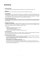
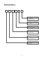
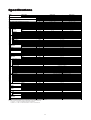
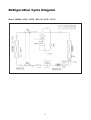
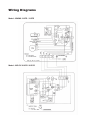
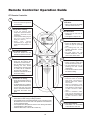
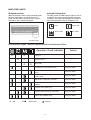
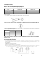
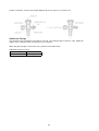
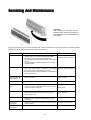
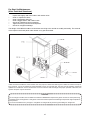
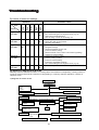
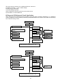
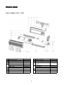
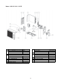
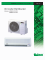
MWMX - 2005
DC Inverter Wall Mounted
Models: MWMX 010FR
MWMX 015FR
REGISTERED
ISO 9002
©2004 McQuay International
+1 (800) 432-1342
www.mcquay.com
Contents
Features ........................................................................................................................ 1
Nomenclature ............................................................................................................... 2
Specifications ............................................................................................................... 3
Operating Range .......................................................................................................... 4
Noise Level ................................................................................................................... 5
Outlines And Dimensions ............................................................................................ 7
Refrigeration Cycle Diagram ....................................................................................... 8
Wiring Diagrams ........................................................................................................... 9
Remote Control Operation Guide .............................................................................. 10
Safety Precautions Before Installation ...................................................................... 14
Special Precautions For R410A ................................................................................. 16
Installation ................................................................................................................... 18
Servicing And Maintenance ........................................................................................ 26
Troubleshooting .......................................................................................................... 28
Parts List ...................................................................................................................... 30
Note : Installation and maintenance are to be performed only by qualified personnel who are
familiar with local codes and regulations, and experienced with this type of equipment.
Caution: Sharp edges and coil surfaces are a potential injury hazard. Avoid contact with them.
Warning : Moving machinery and electrical power hazard. May cause severe personal
injury or death. Disconnect and lock off power before servicing equipment.
This book supersedes MWMX-2004
"McQuay" is a registered trademark of McQuay International. All rights reserved throughout the world.
c 2005 McQuay International
"Bulletin illustrations cover the general appearance of McQuay International products at the time of publication
and we reserve the right to make changes in design and construction at any time without notice."
Features
• Energy Saving
Total energy saved can be as high as 30% compared to the conventionally controlled units.
• Efficient
McQuay DC Inverter series achieve excellent efficient with high EER & COP rating.
• Comfortable
Users enjoy better comfort and quietness with inverter technology. When the environmental factors, such
as temperature, humidity, airflow and / or outside ambient conditions, are obtained and processed through
a control algorithm, the compressor motor speed can be varied to optimize the cooling power to create a
more precisely controlled room temperature (i.e. less temperature fluctuation).
• *R410A Refrigerant (New)
Introducing the new type of refrigerant - R410A which is environmental friendly with zero Ozone Depletion
Potential (ODP=0). R410A also provide the higher volumetric capacity and better refrigerating effect per
unit of volume.
• Advance Technology
The traditional conventional air conditioners repeat “the start” and “the stop” during the thermostat cycle off
and cause the unstable of room temperature. Incorporating fuzzy logic control into the McQuay Inverter
design enables greater flexibility in handling the system control.
This result in :
- Powerful, efficient and economical operation.
- Even room temperature control.
- Constant and quiet compressor operation.
- Enhanced system reliability and reduced maintenance costs.
• Self Diagnostic
Both indoor and outdoor LED Error Code Indicator helps to simplify the troubleshooting process. Where
there’s fault detected during operation, the defect code will indicate the faults.
• Wireless Remote Control
-
The compact LCD transmitter is able to operate the air conditioner unit within the distance of 9 meters.
Fan motor speed can be set at low / medium / high or automatic.
Sleep mode automatically increase set temperature since room temperature is lower at night thus
achieving comfort surrounding.
Airflow direction can be controlled automatically.
Room temperature is controlled by electronic thermostat.
The unit can be preset to on and off automatically for maximum of 15 hours by using timer on/off.
Introducing turbo mode, which allows inverter compressor operates at high power and maximum speed
to achieve required temperature fast.
1
Nomenclature
M
WM
X
010
F
R
Model Type
R : heatpump
Omitted if Cooling
Series
F : F series
Capacity
010 : 10,000 Btu/h
System
X : DC Inverter
Model Name
WM : Wall Mounted
Brand
M : McQuay
2
Specif
ica
tions
Specifica
ications
MODEL
INDOOR UNIT
OUTDOOR UNIT
NOMINAL COOLING CAPACITY
NOMINAL HEATING CAPACITY
COIL
INDOOR UNIT
TUBE
FIN
COIL
PIPE
OUTDOOR UNIT
FAN
COMP.
FIN
TUBE
FAN
RATED TOTAL POWER CONSUMPTION (COOLING)
RATED TOTAL POWER CONSUMPTION (HEATING)
RATED TOTAL RUNNING CURRENT (COOLING)
RATED TOTAL RUNNING CURRENT (HEATING)
POWER SOURCE
REFRIGERANT
HIGH
AIR FLOW
MEDIUM
LOW
FAN MOTOR
INPUT POWER
RUNNING CURRENT
MATERIAL
DIAMETER
THICKNESS
MATERIAL
THICKNESS
ROW
FIN PER INCH
FACE AREA
HEIGHT
DIMENSION
WIDTH
DEPTH
WEIGHT
SOUND PRESSURE LEVEL - H / M / L
ROOM TEMPERATURE
CONTROL
AIR DISCHARGE
OPERATION
CONDENSATE DRAIN SIZE
AIR FILTER
PACKING
HEIGHT
DIMENSION
WIDTH
DEPTH
COMPRESSOR TYPE
RATED RUNNING CURRENT (COOLING)
RATED RUNNING CURRENT (HEATING)
INPUT POWER (COOLING)
INPUT POWER (HEATING)
PROTECTION DEVICE
FAN TYPE / DRIVE
BLADE MATERIAL
DIAMETER
RATED RUNNING CURRENT
MOTOR OUTPUT
RATED INPUT POWER
AIR FLOW
MATERIAL
DIAMETER
THICKNESS
MATERIAL
THICKNESS
ROW
FIN PER INCH
FACE AREA
HEIGHT
DIMENSION
WIDTH (WITH COVER)
DEPTH
WEIGHT
MATERIAL
CASING
THICKNESS
FINISHING
SOUND PRESSURE LEVEL
TYPE
LIQUID
SIZE
GAS
PACKING
HEIGHT
DIMENSION
WIDTH
DEPTH
REFRIGERANT CHARGE
MWMX 010FR
M5LCX 010CR
2,784 (1,084 - 3,516)
9,500 (3,700 - 12,000)
3,370 (1,172 - 4,395)
11,500 (4,000 - 15,000)
730 (300 - 1,000)
1,000 (290 - 1,680)
3.50
4.80
W
Btu/h
W
Btu/h
W
W
A
A
V/Ph/Hz
220 - 240 / 1 / 50
R410A
142 / 300
109 / 230
90 / 190
4P 13W
34
0.15
L/s / cfm
L/s / cfm
L/s / cfm
W
A
mm/in
2
m /ft
mm/in
mm/in
mm/in
kg
dBA
38 / 35 / 30
39 / 36 / 31
FUZZY LOGIC CONTROL
LOUVER (UP & DOWN) & GRILLE (LEFT & RIGHT)
LCD WIRELESS REMOTE CONTROL
16 / 0.63
ANTI-FUNGUS POLYPROPYLENE FILTER
371 / 14.6
875 / 34.4
269 / 10.6
DC BRUSHLESS SCROLL
mm/in
mm/in
mm/in
mm/in
3.2
4.6
632
912
A
A
W
W
4.4
5.0
991
1166
ELECTRONIC CONTROL
PROPELLER / DIRECT
GLASS REINFORCED ACRLY STYRENE RESIN
401 / 15.8
mm/in
A
W
W
L/s / cfm
0.24
0.29
25
35
56
68
378 / 800
425 / 900
SEAMLESS INNER GROOVED COPPER TUBE
7 / 0.276
0.32 / 0.013
ALUMINIUM (HYDROPHILIC)
0.11 / 0.004
2
18
0.35 / 3.78
540 / 21.3
700 (+70) / 27.6 (+2.8)
250 / 9.8
38.0 / 83.8
GALVANISED MILD STEEL
0.8 / 0.031
EPOXY POLYESTER POWDER
mm/in
mm/in
mm/in
2
146 / 310
127 / 270
109 / 230
4P 13W
36
0.15
INNER GROOVED COPPER TUBE
7.0 / 0.276
0.32 / 0.013
ALUMINIUM (HYDROPHILIC)
0.11 / 0.004
2
18
0.198 / 2.131
290 / 11.4
815 / 32.1
181 / 7.1
9.5 / 20.90
mm/in
mm/in
2
MWMX 015FR
M5LCX 015CR
3,516 (1,084 - 3,780)
12,000 (3,700 - 15,000)
4,102 (1,172 - 4,981)
14,000 (4,000 -17,000)
1,095 (300 - 1,780)
1,270 (290 - 1,950)
4.80
5.40
2
m /ft
mm/in
mm/in
mm/in
kg
mm/in
47
dBA
52
FLARE
6.35 / 0.250
mm/in
mm/in
mm/in
mm/in
mm/in
kg
9.52 / 0.375
12.7 / 0.500
601 / 23.7
803 / 31.6
320 / 12.6
0.78 / 1.72
1) ALL SPECIFICATIONS ARE SUBJECTED TO CHANGE BY THE MANUFACTURER WITHOUT PRIOR NOTICE.
2) NOMINAL COOLING AND HEATING CAPACITY ARE BASED ON THE CONDITIONS BELOW :
a) COOLING - 27°C DB / 19°C WB INDOOR AND 35°C DB OUTDOOR
b) HEATING - 21.1°C DB / 15.6°C WB INDOOR AND 8.3°C DB / 6.1°C WB OUTDOOR
3
0.79 / 1.74
Operating Range
Ensure the operating temperature is in allowable range.
Cooling only
Outdoor temp. (°CDB)
Cooling
46
Caution :
35
STD
The use of your air conditioner
outside the range of working
temperature and humidity can
result in serious failure.
19
0
24
15
Indoor temp. (°CWB)
Heatpump
Cooling
Heating
6
Outdoor temp. (°CDB)
Outdoor temp. (°CWB)
18
STD
46
35
STD
19
0
-9
15
21
27
15
24
Indoor temp. (°CWB)
Indoor temp. (°CDB)
4
Noise Le
vel
Lev
Sound Pressure Level (Measured In Anechoic Room)
DC Inverter Wall Mounted Unit
Model
MWMX 010FR
MWMX 015FR
1/1 Octave Sound Pressure Level (dB, ref 20µPa)
Speed
Overall
Noise
(RPM)
125 Hz
250 Hz
500 Hz
1 kHz
2 kHz
4 kHz
8 kHz
A (dBA) Criteria
H (1250)
32
33
35
34
31
23
16
38
33
M (1110)
32
29
32
31
27
18
14
35
30
L (980)
29
26
29
26
21
15
12
30
24
H (1300)
32
34
36
36
32
24
16
39
35
M (1150)
32
30
33
33
29
20
15
36
32
L (1000)
30
26
30
27
22
15
13
31
25
Microphone position: MWMX - F/FR - 1m in front of the unit and 0.8m below the vertical centre line of the
unit. (JIS C 9612)
Model
Measuring location
MWMX 010FR
MWMX 015FR
Standard : JIS C 9612
5
MMWX 010FR NC CURVE
Measured in anechoic room at 1m front and 0.8m below the vertical centre line of the unit
MMWX 015FR NC CURVE
Measured in anechoic room at 1m front and 0.8m below the vertical centre line of the unit
6
Outlines And Dimensions
Indoor Unit
Model : MWMX 010FR / 015FR
Note : Dimension in mm
Outdoor Unit
Model : M5LCX 010CR / 015CR
Note : Dimension in mm
7
Refrigeration Cycle Diagram
Model : MWMX 010FR / 015FR - M5LCX 010CR / 015CR
8
Wiring Diagrams
Model : MWMX 010FR / 015FR
Model : M5LCX 010CR / 015CR
9
Remote Controller Operation Guide
G7 Remote Controller
1
2
Transmission source
• The source where the signal will
be transmitted
Signal transmission
indication
• Blink to confirm the last setting
has been send to the unit.
4
Temperature setting
• To set the desired
•
•
3
room
temperature, press the button to
increase or decrease the set
temperature.
The temperature setting range is
from 16°C to 30°C (Optional
setting 18°C to 30°C).
Press
both
buttons
simultaneously to toggle the
temperature setting between °C
and °F.
On/Off button
• Press once to
•
5
Operation mode
• Press the MODE
•
6
Fan speed selection
• Press the button until
•
the
desired fan speed is achieved.
7
12
ON timer setting
• Press the SET button
•
•
9
will
activate the on timer function.
Set the desired on time by
pressing the SET button
continuously. If the timer is set
to 7.30am, the air conditioner
will turn on at 7.30 sharp.
Press the CLR button to cancel
the on timer setting.
•
Automatic air swing
• Press the SWING button
to
activate the automatic air swing
function.
To distribute the air to a specific
direction, press the SWING button and wait until the louver
move to the desired direction
and press the button once
again.
•
•
•
decreased if in COOL or DRY mode. Fan speed will be increased if it
is not at maximum speed.
The temperature & fan speed will resume to user setting if the button
is pressed again or after 20mins.
Available under HEAT, COOL & DRY modes only.
10
11
will
activate the off timer function.
Set the desired off time by
pressing the SET button
continuously.
Press the CLR button to cancel
the off timer setting.
Sleep mode setting
• Press the button to activate
•
Turbo function (optional-only applicable to inverter unit)
• Press button for fast cooling or heating operation.
• The temperature will be increased internally if it is in the HEAT mode,
button to
select the type of operating
mode.
For cooling only unit, the
available modes are : COOL,
DRY & FAN.
For heat pump unit, the
available modes are : AUTO,
COOL, DRY, FAN & HEAT.
OFF timer setting
• Press the SET button
•
10
•
12
8
start the air
conditioner.
Press again to stop the unit.
sleep mode. This function is
available under COOL, HEAT &
AUTO mode.
When it is activated in COOL
mode, the set temperature will
be increased 0.5°C after 30mins,
1°C after 1 hour and 2°C after 2
hours.
When it is activated in HEAT
mode, the set temperature will
be decreased 1°C after 30mins,
2°C after 1 hour and 3°C after 2
hours.
Clock time setting
• Press button + or - to increase
or decrease the clock time.
INDICATOR LIGHTS
IR signal receiver
Inverted Cooling Unit
When all infrared remote control operating signal
has been transmitted, the signal receiver on
indoor unit will make a (beep) sound to confirm
acceptance of the transmitted signal.
The table shows the LED indicator lights for the air
conditioner unit under normal operation and fault
conditions. The LED indicator lights are located at
the bottom right side of the air conditioner unit.
Timer
Power ON
Sleep mode
Dry mode
LED Indicator Lights : Normal Operation And Fault Indication Table
Operation / Fault Indicator
Action
Timer on
-
Sleep mode on
-
Dry mode
-
Compressor overload protection
Call your dealer
Indoor temperature sensors contact loose /
Call your dealer
short
- ON
/
Outdoor temperature sensors contact
loose / short
Call your dealer
Gas leak / compressor overheat
Call your dealer
Communication error between indoor and
outdoor
Call your dealer
Inverter error / PFC error
Call your dealer
Outdoor total current trip / DC peak
Call your dealer
Indoor fan feedback error
Call your dealer
- ON or OFF
- Blinking
11
Inverter Heatpump Unit
LED Indicator Lights For Inverter Heatpump Unit
Cool / Dry
Heat
Stand-by / Fan
Timer
LED Display
The LED in indoor and outdoor unit indicate operation modes / faults detected
Normal Operation / Fault Condition
Cool / Dry
Heat
Stand by
Action
Timer
/
Cooling mode
-
/
Dry mode
-
Stand-by / Fan mode
-
- ON
/
Heat mode
-
/
Auto mode
-
Defrost operation
-
/
Compressor overload protection
Call your dealer
Indoor temperature sensors contact loose /
short
Call your dealer
Outdoor temperature sensors contact loose /
short
Call your dealer
Gas leak / compressor overheat
Call your dealer
Communication error between indoor and
outdoor
Call your dealer
Inverter error / PFC errore
Call your dealer
Outdoor total current trip / DC peak
Call your dealer
Indoor fan feedback error
Call your dealer
- ON or OFF
- Blinking
12
Compressor Stopped Special Instruction
Keep the main power supply ON
DO NOT TOUCH ANY OF THE WIRES
INSIDE THE UNIT!
Open up the outdoor unit’s top panel
Notice the Green LED on the outdoor P.C. board
Blink
1
2
Count the number of blinks indicated
by the LED
Fault Indication
Outdoor ambient sensor error
Outdoor coil sensor error
Corrective Action
Check ambient sensor wire and connection
Check coil sensor wire and connection
3
Discharge sensor error / Compressor overheat
indication
Check discharge sensor wire and connection /
Not enough refrigerant / Indoor overload
4
5
6
7
8
9
10
11
12
13
14
15
DC compressor feedback
Communication error
Over current
No load
Over / under voltage
DC compressor start failure
Cooling overload
Defrost
IPM Protection
EEPROM read error
EEPROM write error
DC fan motor no feedback
Call local dealer
Check interconnection communication wire
Call local delaer
Check compressor wire and connection
Check power supply
Call local dealer
Check whether outdoor unit is blocked or not
Wait till defrost is over then restart
Check IPM
Change EEPROM
Change EEPROM
Check fan motor wire connection
*If the problem persist, contact your local delaer straight away.
Normal Running Mode Condition
If the air conditioner unit has no faulty indication and the compressor is running at normal mode, the
outdoor P.C. board’s LED indication will blink at a slower paste. The table below shows the significant
meaning of different running mode and limitation for this air conditioner unit.
One must not attemp to see the LED indication blinking unless intructed to do so.
Blinks
1
2
3
4
5
6
7
8
Blinking indication
Normal running, with no limitation
Voltage limit
Heating unit : Indoor cooil temperature limit
Total current limit
Discharge temperature limit
Cooling unit : Indoor coil temperature limit
Indoor fan control
Outdoor frequency adjustment
13
Safety Precautions Before Installation
Before Operating, Please Read The Following “Safety Precautions” Carefully.
To prevent injury to the user or other people and properties damage, the following instructions must be followed.
• Incorrect operation due to ignoring of instruction will cause harm or damage, the seriousness is classified
by the following indications.
Warning: This sign indicates the possibility of causing death or serious injury.
Caution:
This sign indicates the possibility of causing injury or damage to properties only.
Warning
•
•
This unit must be installed by a qualified technician.
All field wiring must accordance to the National Wiring Regulation.
Important
The wires in this mains lead are coloured in accordance with the following code:
Green and yellow
Blue
Brown
Earth
Neutral
Live
As the colours of the wires in the mains lead of this appliance may not correspond with the coloured
markings identifying the terminals in your plug, proceed as follows:
• The wire which is coloured green and yellow must be connected to the terminal in
the plug which is marked with the earth symbol
or coloured green or green and yellow.
• The wire which is coloured blue must be connected to the terminal which is
marked with the letter N or coloured black.
• The wire which is coloured brown must be connected to the terminal which is
marked with letter L or coloured red.
Note
If the supply cord is damaged, it must be replaced by the special cord obtainable at authorized service/
parts centers.
This unit is not provided with a plug, therefore the power supply wire must be connected by a qualified
chargeman.
Caution
Remove power plug or disconnect from the mains before servicing the appliance.
14
Symbol (with white background) denotes item that is PROHIBITED from doing.
Symbol (with black background) denotes item that is COMPULSORY to be carried out.
Caution
Please confirm the following important points when installation
• Grounding is necessary
It may cause electrical shock if grounding is not perfect.
• Do not install the unit where leakage of flammable gas may occur
In case of gas leaks and accumulates at the surrounding of the unit, it may cause fire
ignition.
• Confirm drainage piping is connected properly
If it is not connected perfectly, it may cause water leakage and dampen the
furniture.
• Confirm the unit is switched off before install, service or maintain the unit
If it is not switched off, it may cause injury to the installer by any of the moving part
especially fan.
• Do not overcharge the unit
This unit is factory pre charged. Over charge will cause over current or damage to
the compressor.
Refer to page 25 in case of top up charge is necessary.
• Confirm cover back the unit panel after servicing or installation
Unsecure panel will cause unit noisy.
15
Special Precautions For R410A
SPECIAL PRECAUTIONS WHEN DEALING WITH REFRIGERANT R410A UNIT
1) WHAT IS NEW REFRIGERANT R410A?
R410A is a new HFC refrigerant which does not damage the ozone layer. The working pressure of this new refrigerant
is 1.6 times higher than conventional refrigerant (R22), thus proper installation / servicing is essential.
2) COMPONENTS
Mixture weight composition
R32(50%) and R125(50%)
3) CHARACTERISTIC
•
•
•
R410A liquid and vapor components have different compositions when the fluid evaporates or condenses. Hence,
when leak occurs and only vapor leaks out, the composition of the refrigerant mixture left in the system will change
and subsequently affect the system performance. DO NOT add new refrigerant to leaked system. It is recommended
that the system should be evacuated thoroughly before recharging with R410A.
When refrigerant R410A is used, the composition will differ depending on whether it is in gaseous or liquid phase.
Hence when charging R410A, ensure that only liquid is being withdrawn from the cylinder or can. This is to make
certain that only original composition of R410A is being charged into the system.
POE oil is used as lubricant for R410A compressor, which is different from the mineral oil used for R22 compressor.
Extra precaution must be taken not to expose the R410A system too long to moist air.
4) CHECK LIST BEFORE INSTALLATION/SERVICING
•
•
•
•
Tubing
Refrigerant R410A is more easily affected by dust of moisture compared with R22, make sure to temporarily cover
the ends of the tubing prior to installation
Compressor oil
No additional charge of compressor oil is permitted.
Refrigerant
No other refrigerant other that R410A
Tools (size of service port is different from R22 system)
Tools specifically for R410A only (must not be used for R22 or other refrigerant)
i)
Manifold gauge and charging hose
ii)
Gas leak detector
iii) Refrigerant cylinder/charging cylinder
iv) Vacuum pump c/w adapter
v) Flare tools
vi) Refrigerant recovery machine
5) HANDLING AND INSTALLATION GUIDELINES
Like R22 system, the handling and installation of R410A system are closely similar. All precautionary measures; such as
ensuring no moisture, no dirt or chips in the system, clean brazing using nitrogen, and thorough leak check and vacuuming
are equally important requirements. However, due to its hydroscopic POE oil, additional precautions must be taken to
ensure optimum and trouble free system operation.
a)
During installation or servicing, avoid prolong exposure of the internal part of the refrigerant system to moist air.
Residual POE oil in the piping and components can absorb moisture from the air.
b)
Ensure that the compressor is not expose to open air for more than the recommended time specified by its manufacturer
(typically less than 10 minutes). Removed the seal plugs only when the compressor is about to be brazed.
c)
The system should be thoroughly vacuumed to 1.0 Pa ( 700mmHg) or lower. This vacuuming level is more stringent
than R22 system so as to ensure no incompressible gas and moisture in the system.
16
d) When charging R410A, ensure that only liquid is being withdrawn from the cylinder or can. This is to
ensure that only the original composition of R410A is being delivered into the system. The liquid
composition can be different from the vapor composition.
Invert cylinder
without dip-pipe
Dip-pipe
Liquid
withdrawal
f)
Normally, the R410A cylinder or can is being equipped with a dip pipe for liquid withdrawal. However, if
the dip pipe is not available, invert the cylinder or can so as to withdraw liquid from the valve at the
bottom.
17
Installation
Installation Diagram
Indoor Unit
Outdoor Unit
CAUTION : Before installing the unit, ensure that the power supply matches the power requirement of the air
conditioner
18
1) Selection Of Location And Space
(A) Indoor Unit
Install the fan coil (indoor) unit at a location with the following requirements
• Location is suitable for wiring, piping and drainage.
• No obstruction of air flow into and out of unit where cooler air can be evenly distributed.(See fig. 1)
• Ensure that air discharge is not short circuited with air intake.
• Ensure that wall is sufficiently strong, rigid, flat, perpendicular and vibration free.
• Where air filter cassette can be slided in or out easily.
• Where there is no danger of flammable gases.
• Where there is no direct sunlight on unit.
• Also to take into consideration a place for the installation of the Wireless LCD Remote Controller.
MAINTENANCE & SERVICING SPACE
AIR FLOW DIRECTION
CAUTION : Do not install unit near the door way
because excessive fresh air may cause
panel condensation on the unit.
Fig. 1
19
(B) Outdoor Unit
As condensing temperature rises, evaporating temperature rises and cooling capacity drops. In order to achieve maximum
cooling capacity, the location selected for outdoor unit should fulfill the following requirements :
•
Install the condensing (outdoor) unit in a way such that hot air distributed by the outdoor condensing unit cannot be
drawn in again (as in the case of short circuit of hot discharge air). Allow sufficient space for maintenance around the
unit.
•
Ensure that there is no obstruction of air flow into or out of the unit. Remove obstacles which block air intake or
discharge.
•
•
•
The location must be well ventilated, so that the unit can draw in and distribute plenty of air thus lowering the condensing
temperature.
A place capable of bearing the weight of the outdoor unit and isolating noise and vibration.
A place protected from direct sunlight. Otherwise use an awning for protection, if necessary.
•
The location must not be susceptible to dust or oil mist.
Installation Clearance
•
Outdoor units must be installed such that there is no short circuit of the hot discharge air or obstruction to smooth air
flow. Select the coolest possible place where intake air should not be hotter than the outside temperature (max. 45°C)
ALL MODELS
Minimum Distance
A
B
C
D
300 mm
1000 mm
300 mm
500 mm
CAUTION : If the condensing unit is operated in an atmosphere containing oils(including machine oils),
salt(coastal area), sulphide gas(near hot spring, oil refinery plant), such substances may lead to failure of the
unit.
20
2) Drilling Holes And Mounting Installation Plate
CAUTION:
i) Please check the unit weight for each model. Always ensure that the wall is sufficiently strong to withstand
the weight. If not, it is necessary to reinforce the wall with plate, beams or pillars.
ii) The unit cannot be directly fixed onto the wall or the likes. In all cases, the installation plate provided MUST
be used.
• Paste the installation plan provided on the desired location on the wall and mark the holes location
accordingly.
• Ensure that the minimum maintenance and servicing space at the top, left and right side of the unit is
reserved.
• Ensure also the levelness of the installation plate.
• Drill the screw mounting holes (minimum 4 screws are required).
• Drill the pipe hole at the location as per plan. (This is only applicable for rear piping outlet installation).
Note: The hole should be drilled slightly lower at outdoor side as per figure below:--
• Fix the installation plate firmly to wall, without tilting to left or right. Use a plumb line, if available.
• Fixing method:WOODEN
FRAME WALL
REINFORCED CONCRETE BUILDING
NUT ANCHOR
21
BOLT ANCHOR
3) Indoor Unit Preparation
• Carefully bend the pipes to the required position to
• The refrigerant piping can be routed to the unit in 5
direction, by using the cut outs in the unit casing.
(See fig. 1)
align with the hole. For right hand and rear side draw
out, hold the bottom of the piping and fix direction
before shaping it to the desired position (See fig. 2).
The condensation drain hose should be taped to the
pipes with vinyl tape. The electrical cable can also be
taped to the pipes.
4) Mounting Indoor Unit
Hook the indoor unit onto the upper portion of installation plate. (Engage the 2 hooks of rear top of the indoor unit with
the upper edge of the installation plate). Ensure the hooks are properly seated on the installation plate by moving in left
and right.
1. Hook the unit into the
installation plate.
2. Fix the rivet underneath after completion
of installation
22
5) Water Drainage Piping
The indoor drain pipe must be downward gradient for smooth drainage. Avoid situation as shown in figure
below.
6) Wiring
Electrical Connection
• Wiring regulation on wire diameters differ from country to country. Please refer to your LOCAL ELECTRICAL
CODES for field wiring rules. Be sure that installation comply with such rules and regulations.
General Precautions
• Ensure that the rated voltage of the unit corresponds to the name plate before carrying out proper wiring
according to the wiring diagram.
• Provide a power outlet to be used exclusively for each unit. A power supply disconnect and a circuit
breaker for over current protection should be provided in the exclusive line.
• The unit must be GROUNDED to prevent possible hazards due to insulation failures.
• All wiring must be firmly connected.
• All wiring must not touch the hot refrigerant piping, compressor or any moving parts of fan motors.
• The field wires from the indoor unit must be clamped on the wire clamp as per shown in the figure.
23
7) Refrigerant Piping
Maximum Pipe Length And Maximum Number Of Bends
Always choose the shortest path for refrigerant piping and follow the recommendations as tabulated below:
Model
Data
Max. Length, L (m)
Max. Elevation, H (m)
Max. No. of Bends
MWMX 010FR
MWMX 015FR
12
5
10
12
5
10
Flare Connection
•
Cut the pipe stages by stages, advancing the blade of pipe cutter slowly.
• Remove burr with the burr remover. Hold the flaring end down to prevent burrs from dropping inside pipe.
• The exact length of pipe protruding from the face of the flare die is determined by the flaring tool. The table shows the
use of an imperial die and riged die.
PIPE ∅, D (mm)
6.35 (1/4”)
A(mm)
IMPERIAL DIE
RIGED DIE
1.3
0.7
9.52 (3/8”)
1.6
1
12.7 (1/2”)
1.9
1.3
15.88 (5/8”)
2.2
1.7
Fix the pipe firmly on the flare die. Match the centers of both the flare die and the flaring punch, and tighten
flaring punch fully.
8) Vacuuming And Charging
• The precharged outdoor unit does not need any vacuuming or charging. However once it is connected, the
connecting pipe line and the indoor need to be vacuumed before releasing the R22/R407C/R410A from
the outdoor unit.
1) Open the service port core cap.
2) Connect pressure gauge to the service port.
3) Connect the line to vacuum pump. Open the charging manifold valve and turn the pump on. Vacuum to
–0.1 MPa (-760mmHg) or lower. (Evacuation time varies by the pump but averagely in 1 hour).
24
4) After evacuation, unscrew the spindle (diagram B) for the gas to run to indoor unit.
Additional Charge
The refrigerant gas is charged in the outdoor unit and, if the piping length is less than 7.6m, additional
charge of the refrigerant after vacuuming is not necessary.
When the piping length is more than 7.6m, please use the table below :
Additional charge per meter
Model
MWMX 010/015 FR
R410A
20g / m
25
Ser
vicing And Maintenance
Servicing
CAUTION:
After installing or servicing the unit,
please ensure that the front panel is
secured by the 1 hook underneath the
front panel.
The unit is designed to give a long life operation with minimum maintenance required. However, it should be regularly
checked and the following items should be given due attention.
Components
Maintenance Procedure
Recommended Schedule
Indoor Air Filter
1 . Remove any dust adhering on the filter by using a
vacuum cleaner or wash in lukewarm water (below
40°C/104°F) with a neutral cleaning detergent.
2. Rinse the filter well and dry before placing it back onto
the unit.
3. Do not use gasoline, volatile substances or chemicals
to clean the filter.
At least once every 2 weeks.
More frequently if necessary.
Indoor Unit
1. Clean any dirt or dust on the grille or panel by wiping it
with a soft cloth soaked in lukewarm water (below
40°C/104°F) and a neutral detergent solution.
2. Do not use gasoline, volatile substances or chemicals to
clean the indoor unit.
At least once every 2 weeks.
More frequently if necessary
Condensate Drain
Pan and Pipe
1. Check and clean.
Every 3 months.
Indoor Fan
1. Check for unusual noise.
As necessary.
Indoor/Outdoor
Coil
1. Check and remove dirt which are clogged between fins.
2. Check and remove obstacles which hinder air flow in
and out of indoor/outdoor unit.
Every month.
Electrical
1. Check voltage, current and wiring.
2. Check faulty contacts caused by loose connections,
foreign matters, etc.
Every 2 months.
Every 2 months.
Compressor
1.
Every 6 months.
Compressor
Lubrication
1. Oil is factory charged. Not necessary to add oil if circuit
remains sealed.
No maintenance required.
Fan Motors
Lubrication
1. All motors pre-lubricated and sealed at factory.
No maintenance required.
No maintenance needed if refrigerant circuit remains
sealed. However, check for refrigerant leak at joints
and fittings.
26
Every month.
Pre Start Up Maintenance
(After Extended Shutdown)
–
–
–
–
–
–
–
Inspect thoroughly and clean indoor and outdoor units.
Clean or replace air filters.
Clean condensate drain line.
Clean clogged indoor and outdoor coils.
Check fan imbalance before operation.
Tighten all wiring connections and panels.
Check for refrigerant leakage.
The design of the M5LCX outdoor series allows servicing to be carried out readily and easily. The removal
of the top/front and back panel make almost every part accessible.
Under normal circumstances, these outdoor units only require a check and cleaning of air intake coil surface once quarterly. However, if a unit is installed in areas subjected to much oil mist and dust, the coils must be regularly cleaned by
qualified Air Conditioner Service Technicians to ensure sufficient heat exchange and proper operation. Otherwise, the
systems life span may be shortened.
CAUTION!
Do not charge OXYGEN, ACETYLENE OR OTHER FLAMMABLE and poisonous gases into the unit when performing
a leakage test or an airtight test. These gases could cause severe explosion and damage if exposed to high temperature
and pressure.
It is recommended that only nitrogen or refrigerant be charged when performing the leakage or airtight test.
27
Troub
leshooting
oubleshooting
By means of pressure readings :
Too
High
A Little
High
PROBABLE CAUSE
Normal
Circuit
Too
Low
Data
A Little
Low
PRESSURE
High Side
Low Side
1. Overcharged with refrigerant.
2. Non-condensable gases in refrigerant circuit (e.g. oil).
3. Obstructed air-intake/discharge.
4. Short circuiting of hot air at condensing unit.
1. Poor compression/no compression (compressor defective.)
2. Check valve stick in open position.
3. Reversing valve leaking.
1. Undercharged with refrigerant.
2. Refrigerant leakage.
3. Air filter clogged/dirty (indoor unit).
4. Indoor fan locked (cooling).
5. Defective defrost control, outdoor coil freezed up (heating).
6. Outdoor fan locked (heating).
1. Outdoor fan blocked (cooling).
2. Outdoor coil dirty (cooling).
3. Indoor fan locked (heating).
4. Indoor filter clogged/dirty (heating).
5. Non-condensable gases in refrigerant circuit (e.g. air).
1. Air intake temperature of indoor unit too high.
High Side
Low Side
High Side
Low Side
High Side
Low Side
High Side
Low Side
By means of diagnosis flow chart
Generally, there are two kinds of troubles, i.e. starting failure and insufficient cooling/heating. “Starting Failure” is
caused by electrical defect while “Insufficient Cooling/Heating” is caused by improper application or defects in
refrigerant circuit.
1) Diagnosis of electric circuit
No Cooling / Heating
Unit fail to start
Check power supply
- voltage
- phase
- frequency
Check settings of remote control box
Check power source cord
Check circuit breake & fuse
Fan fails to start
Compressor fails to start
Fan Motor Capacitor defective
Thermostat setting too high
Loose Connections,
Contactors
Protection Device Actuated
Irregular motor resistance (Ω )
& insulation (M Ω )
Reset
Voltage supply not within range
Loose Connections,
Improper wiring
Compressor
Capacitor Defective
Check motor resistance ( Ω ) and insulation (M Ω )
Replace Fan Motor
Regular but fails
to start
Irregular
Compressor locked (to replace compressor)
Compressor Motor damaged ( to replace compressor)
28
The most common causes of air conditioner failure to “start” are :
a) Voltage not within +/- 10% of rated voltage.
b) Power supply interrupted.
c) Control settings improper
d) Air Conditioner is disconnected from main power source.
e) Fuse blown or circuit breaker off.
II) Diagnosis Of Refrigerant Circuit /Application
There might be some cases where the unit starts running but does not perform satisfactory, i.e. insufficient
cooling. Judgement could be made by measuring temperature difference of indoor unit’s intake and discharge
air as well as running current.
Insufficient Cooling
Unit Starts
Check air circulation
High cooling load
Refrigerant circuit
Indoor/Outdoor coil dirty
(clogged)
Air filters dirty
Fan Malfunction
Obstruction at air inlet/outlet
of indoor/outdoor unit
Leakage
Excessive heat
source e.g. electric
kettle
Restriction e.g. at
strainer, capillary,
filter dryer, etc.
Room overcrowded
with people
Compressor
Windows / doors
wide open
Less or no compression
(Low running current)
Satisfactory operation with temperature difference of
air intake & discharge of indoor unit 10°C - 15°C
Insufficient Heating
Unit Starts
Check air circulation
High heating load
Refrigerant circuit
Indoor/Outdoor coil dirty (clogged)
Leakage
Air filters dirty
Restriction e.g. at
strainer, capillary,
filter dryer, etc.
Fan Malfunction
Compressor
Obstruction at air inlet/outlet
of indoor/outdoor unit
Less or no compression
(Low running current)
Satisfactory operation with temperature difference of
air intake & discharge of indoor unit 16°C - 25°C
29
Windows / doors
wide open
Par
ts List
arts
Model : MWMX 010FR / 015FR
1
Assy, Mounting Plate
A50013032957
10 Fan Bush C/Flow Fan Black
A11014029514
2
Clamp, Piping 10/15F
A12014048332
11 Evaporator Coil Assy.
A50024036001
3
Assy, Chasis
A50124048326
12 Front Cover Assy
A50124061936
4
Fan Motor
A03039017867
14 Handset, wireless G7 HP Turbo
A04084049718
Control Box
5
(McQuay)
MWMX 010FR
A50044061964
MWMX 015FR
A50044061678
15 CONTROL MODULE
MWMX 010FR
A04084061417
6
Control Box Cover
A50124032946
MWMX 015FR
A04084061416
7
Assy, Air Discharge Housing
A50123032954
8
Rivet
A07074049285
Titanium Oxide Filter
A03089016310
9
Crossflow Fan 687.0 x 636.0
A03024032878
3M Ionizer filter
A03089016307
16 Filter Frame
30
A12013029414
Model : M5LCX 010 / 015CR
1
2
3
4
5
6
7
8
ASSY,PAN BASE SL10/15C
A50014057190
ASSY,CONDENSER COIL 5SL10/15C/10CR
M5LCX 010CR
A50024065385
M5LCX 015CR
A50024058635
ASSY. VALVE BRACKET
A01014051164
ASSY. CAPILLARY TUBE
M5LCX 010CR
A50024055287
M5LCX 015CR
A50024058572
ASSY. COMPRESSOR
A04019015856
ASSY. PANEL LEFT
A01014051166
ASSY. PANEL RIGHT
A01014051167
BRACKET, MOTOR
A01014051162
9
10
11
12
13
14
15
31
ASSY. CONTROL BOX
M5LCX 010CR
M5LCX 015CR
FAN
MOTOR
M5LCX 010CR
M5LCX 015CR
ASSY. FRONT PANEL
ASSY. VALVE COVER
ASSY. TERMINAL BOX COVER
DRIER, FILTER
A50044061024
A50044061025
A03019015339
A03039016892
A03039016893
A01014051171
A50124051173
A01014056885
A02169017980
©2005 McQuay International
+1 (800) 432-1342
www.mcquay.com