1
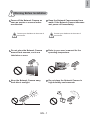
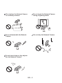
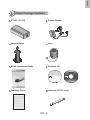
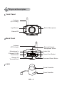
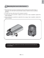
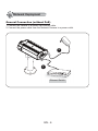
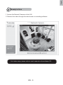
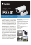
English
Warning Before Installation
Power off the Network Camera as
soon as smoke or unusual odors
are detected.
Contact your distributor in the event of
occurrence.
Keep the Network Camera away from
water. If the Network Camera becomes
wet, power off immediately.
Contact your distributor in the event of
occurrence.
Do not place the Network Camera
around heat sources, such as a
television or oven.
Refer to your user’s manual for the
operating temperature.
Keep the Network Camera away
from direct sunlight.
Do not place the Network Camera in
high humidity environments.
EN - 1
Do not place the Network Camera
on unsteady surfaces.
Do not touch the Network Camera
during a lightning storm.
Do not disassemble the Network
Camera.
Do not drop the Network Camera.
Do not insert sharp or tiny objects
into the Network Camera.
EN - 2
English
1
Check Package Contents
IP7153 / IP7154
Power Adapter
Camera Stand
Lens
Quick Installation Guide
Software CD
ST7501
Central Management Software
Warranty Card
Antenna (IP7154 only)
EN - 3
2
Physical Description
Front Panel
Antenna
(IP7154 only)
Built-in Microphone
Light Sensor
Status LED
Back Panel
Antenna
(IP7154 only)
External/Internal
Microphone Switch
Audio Out
Microphone In
Ethernet 10/100
RJ45 Socket
Power Cord Socket
General I/O
Terminal Block
Recessed Reset Button
Lens
Focus Controller
Zoom Controller
EN - 4
English
3
Mounting the Lens to the Camera
1. Mount the lens by turning it clockwise onto the camera mount until it stops. If
necessary, turn the lens counterclockwise slowly to achieve the best optimum
spacing.
2. Connect the lens cable plug to the camera connector.
3. Unscrew the zoom controller to adjust the zoom factor. Upon completion, tighten the
zoom controller.
4. Unscrew the focus controller to adjust the focus range. Upon completion, tighten the
focus controller.
1
∞
N
4
T
W
2
3
For further setup, please refer to the lens' instruction manual inside the
lens package.
EN - 5
4
Network Deployment
General Connection (without PoE)
1. Connect the camera to a switch via Ethernet cable.
2. Connect the power cable from the Network Camera to a power outlet.
2
1
POWER
COLLISION
1
2
3
4
5
LINK
RECEIVE
PARTITION
Ethernet Switch
EN - 6
English
Power over Ethernet (PoE) (IP7153 only)
When using a PoE-enabled switch
This Network Camera is PoE-compliant, allowing transmission of power and data via
a single Ethernet cable. Follow the below illustration to connect the Network Camera
to a PoE-enabled switch via Ethernet cable.
POWER
COLLISION
1
2
3
4
5
LINK
RECEIVE
PARTITION
PoE Switch
When using a non-PoE switch
Use a PoE power injector (optional) to connect between the Network Camera and a
non-PoE switch.
PoE Power Injector
(optional)
POWER
COLLISION
1
2
3
4
5
LINK
RECEIVE
PARTITION
Non-PoE Switch
EN - 7
5
Assigning an IP Address
1. Install "Installation Wizard 2" from the Software Utility directory on the software CD.
2. The program will conduct an analysis of your network environment. After your network
is analyzed, please click on the "Next" button to continue the program.
Installation
Wizard 2
3. The program will search for VIVOTEK Video Receivers, Video Servers, and Network
Cameras on the same LAN.
4. After searching, the main installer window will pop up. Click on the MAC that matches
the one labeled on the bottom of your device to connect to the Network Camera via
Internet Explorer.
Network Camera
Model No:IP7153
MAC:0002D1070417
00-02-D1-07-04-17
192.168.0.219
0002D1070417
RoHS
This device complies with part 15 of the FCC rules. Operation is subject to
the following two conditions:
(1)This device may not cause harmful interference, and
(2) this device must accept any interference received, including interference
that may cause undesired operation.
Pat. 6,930,709
Made in Taiwan
EN - 8
IP7153
English
6
Ready to Use
1. Access the Network Camera on the LAN.
2. Retrieve live video through the web browser or recording software.
For further setup, please refer to user's manual on the software CD.
EN - 9
7
Configure the Wireless Connection (IP7154 only)
1. Check the SSID for your wireless access point (AP).
2. Go to the IP7154 Configuration page > Advanced mode > Wireless LAN.
3. Type in the SSID the same as
your AP.
4. Select the Wireless mode as
"Infrastructure".
5. Click Save. The Network
Camera will reboot.
6. Wait for the live image to be reloaded to your
browser. Then, unplug the power cable and Ethernet
cable from the Network Camera.
7. Replug the power cable to the camera. The Network
Camera will now operate in wireless mode.
ADSL/Cab
le/Hub
AP
POWER
COLLISION
1
2
3
4
5
LINK
RECEIVE
PARTITION
Note:
te:
1. SSID, abbreviated from Service Set Identifier, is the name assigned to the wireless
network. The IP7154 factory SSID setting is set to "default".
2. Select "Ad-Hoc" wireless mode if you want the IP7154 to communicate without
using an AP or wireless router.
For further setup, please refer to the user's manual on the software CD.
EN - 10
Progressive Scan CCD
Quick Installation Guide
English
繁中
簡中
日本語
Français
Español
Deutsch
Português
Italiano
Türkçe
Polski
Русский
Česky
Svenska
IP7153/IP7154
Copyright
P/N: 625009000G Ver.1.01
2009 VIVOTEK INC. All right reserved.
This guide describes the basic functions of IP7153/IP7154.
All detailed information is described in the user's manual.
IP Sur veillance