1
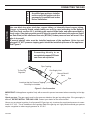
INSTALLATION AND OPERATING INSTRUCTIONS
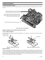
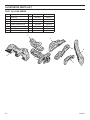
Shown with
Log Set
VDY24/18D5
Shown with
Log Set
VDY30D3R
Shown with
Log Set
VDY24/18D2A
Shown with
Log Set
VDY24/18D4
MODELS:
VDY24/18 - VDY30
Natural Gas or Propane/LPG
Control Type: Manual and Millivolt
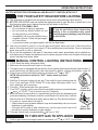
WARNINGS
If the information in this manual is not followed exactly,
a fire or explosion may result causing property damage,
personal injury or loss of life.
– Do not store or use gasoline or other flammable
vapors and liquids in the vicinity of this or any
other appliance.
– WHAT TO DO IF YOU SMELL GAS
Approved to ANSI Z21.60
This gas log set is to be installed only
in a solid-fuel burning fireplace with a
working flue constructed of noncombustible material.
• Do not try to light any appliance.
• Do not touch any electrical switch; do not use any
phone in your building.
• Immediately call your gas supplier from a neighbor's
phone. Follow the gas supplier's instructions.
• If you cannot reach your gas supplier, call the
fire department.
– Installation and service must be performed
by a qualified installer, service agency or the
gas supplier.
READ AND SAVE THESE INSTRUCTIONS
32D1999 2/10 Rev. 9
table of contents
Important Safety Information ..........................3
Fireplace Draft Test ........................................23
Getting Started ................................................4
Flame Appearance . ........................................24
Product Specifications ....................................5
Operating Instructions ...................................25
For Your Safety Read Before Lighting ........25
Manual Control Lighting Instructions . .........25
Millivolt Control Lighting Instructions . .........26
Product/Features Specifications.....................6
Placement in a Fireplace with a Restrictive
Barrier ..........................................................7
Installation ........................................................8
Connecting the Gas...........................................9
Electrical Wiring (Millivolt)..............................11
Log Placement ................................................12
DUZY II VDY24/18D2, VDY24/18D2A and
24/18VDYD2A Log Installation.....................12
Duzy II VDY30D2, VDY30D2A and 30VDYD2A Log Installation.....................................13
VDY24/18D4 Log Installation.......................13
VDY24/18D3R Log Installation...................14
VDY30D4 Log Installation............................14
VDY30D3, VDY30D3R and 30VDYD3A Log
Installation....................................................15
VDY24/18D4 Log Installation.......................17
VDY30D4 Log Installation ..........................18
DUZY 5 Log VDY24/18D5 Log Installation..19
30VDYD5 and VDY30D5 Log Installation...21
Optional Remote Receiver (Millivolt).............27
Cleaning and Servicing . ................................28
Illustrated Parts List .......................................29
Troubleshooting .............................................33
Massachusetts Requirements........................35
Warranty...........................................Back Cover
32D1999
IMPORTANT SAFETY INFORMATION
INSTALLER
OWNER
Please leave these instructions with the appliance.
Please retain these instructions for future reference.
IMPORTANT
WARNING
Read these instructions carefully before installing or trying to operate this gas log set.
Any modification to this gas log set or its controls can be dangerous. Improper
installation or use of the gas log set can cause serious injury or death from fire, burns,
explosion or carbon monoxide poisoning.
1. The installation, combustion and ventilation air must conform with local codes or, in the absence of local codes,
with the National Fuel Gas Code, ANSI Z223.1.
2. This unit complies with ANSI Z21.60 • CSA 2.26 Decorative Gas Appliance for Installation in Solid-Fuel Burning
Fireplace.
3. Installation and repair should be done by a qualified service person. MHSC Vented Gas Logs must be installed
only in a solid-fuel (wood) burning fireplace which can
only be constructed of non-combustible material, with
minimum venting requirements, see installation section.
4. To prevent malfunction, gas log set and flue should
be cleaned at least annually by a professional service
person. More frequent cleaning may be required due
to excessive lint from carpeting, etc. It is imperative that
control compartments, burners and circulating air passageways be kept clean.
5. Correct installation of the ceramic fiber logs, and annual
cleaning are necessary to minimize problems with sooting. See log placement instructions for proper installation.
6. A damper clamp must be installed to provide the minimum permanent vent opening to vent flue products, See
installation instructions.
11. Young children should be carefully supervised when they
are in the same room with the gas log set in operation.
12. Do not place clothing or other flammable material near
the fireplace when the gas logs are in use.
13. Do not use this gas log set if any part has been underwater. Immediately call a qualified service technician to
inspect the gas logs and replace any part of the control
system and any gas control which has been under
water.
14. The gas log set and its individual shutoff valve must be
disconnected from the gas supply piping system during
any pressure testing of the gas supply piping system at
test pressures in excess of 1/2 psig (3.5kPa).
15. The gas log set must be isolated from the gas supply
piping system by closing its individual manual shutoff
valve during any pressure testing of the gas supply piping
system at test pressures equal to or less than 1/2 psig
(3.5kPa).
16. FOR MASSACHUSETTS RESIDENTS ONLY:
Installation of this vented gas log in the Commonwealth
of Massachusetts requires the damper be permanently
removed or welded in the full open position. In addition,
a naturally vented gas log may not be installed in a
bedroom or bathroom in the commonwealth of Massachusetts.
8. This appliance must not be used with glass doors
in the closed position. Provisions for adequate combustion air must be provided, adequate combustion air
usually results in all flames curling into the fireplace away
from screen and up the flue.
9. Keep room area clear and free from combustible materials, gasoline and other flammable vapors and liquids.
10. Children and adults should be alerted to the hazard of
high surface temperature and should stay away to avoid
burns or clothing ignition.
32D1999
warning
7. Never burn solid fuels in a fireplace where a gas log set
is installed.
This appliance is for installation
only in a solid fuel burning fireplace
(masonry fireplace or manufactured
fireplace)
GETTING STARTED
Make sure you have received all parts:
Check your packing list to verify that all listed parts have been received. You should have the following:
BURNER - GRATE ASSEMBLY 24/18, 30
• Burner and Grate Weldment Assembly
• Lava Rocks (2)
• Glowing Embers (Rock Wool)
• Damper Clamp
• Installation /Operating Instructions
• Masonry Screws (2)
• 3/8" Aluminum tube with 3/8" 90° elbow, 1/2" to 3/8" tube fitting
CERAMIC FIBER or refractory cement LOGS 24/18, 30
caution
• Individual Logs
• Installation Instructions
• Handle the gas log burner assembly by the grate only. Do not pick the unit up by the
burner.
• Gloves are recommended when handling ceramic fiber logs to prevent skin irritation
from loose fibers. Logs are fragile — handle with care.
Carefully inspect the contents for shipping damage. If any parts are missing or damaged, immediately inform the
dealer from whom you purchased the appliance. Do not attempt to install any part of the appliance unless
you have all parts in good condition.
ITEMS REQUIRED FOR INSTALLATION
Ensure that the following items are available before proceeding with installation:
• External regulator (for propane/L.P.G. only) • Manual shutoff valve
• Piping which complies with local codes
• Pipe wrench
• Tee joint
• Pipe sealant approved for use with propane/L.P.G. (Resistant to sulfur compounds)
• Drill with masonry bit (for mounting to the floor)
32D1999
PRODUCT SPECIFICATIONS
Natural Gas
Manual Pressure Millivolt Pressure
Regulator Pressure Setting: w.c.
Gas Inlet Pressure:
Max. 10 1/2" w.c.
Min. 6" w.c.
4" w.c.
Regulator Pressure Setting: 4 . 0 "
Gas Inlet Pressure: Max. 10 1/2" w. c. • Min. 6" w.c.
Model Number
Pilot
Control Type
Gas Rate Min BTU/Hr
VDY24/18NMP
Yes
Manual (Thermocouple)
50,000
VDY24/18NVP
Yes
Millivolt (Thermopile)
50,000
VDY30NMP
Yes
Manual (Thermocouple)
65,000
VDY30NVP
Yes
Millivolt (Thermopile)
65,000
Propane/LPG
Note: An external regulator is required to reduce supply pressure to a maximum of 13" w.c.
Manual Pressure
Millivolt Pressure
Regulator Pressure Setting: 10" w.c. Regulator Pressure Setting: 10" w.c.
Gas Inlet Pressure: Maximum 13" w.c.
Gas Inlet Pressure: Maximum 13" w.c.
Minimum 11" w.c. Minimum 11" w.c.
Model Number
Pilot
Control Type
Gas Rate Min BTU/Hr
VDY24/18PMP
Yes
Manual (Thermocouple)
50,000
VDY24/18PVP
Yes
Millivolt (Thermopile)
50,000
VDY30PMP
Yes
Manual (Thermocouple)
65,000
VDY30PVP
Yes
Millivolt (Thermopile)
65,000
Ignition controls
Piezo ignitor allows ignition of the pilot without the use of matches or batteries.
Manual control with pilot has three (3) positions:
OFF - All gas to the gas logs is shut off at the valve.
IGN - Valve position to light/maintain a standing pilot.
ON - Valve position to light/maintain the gas burner.
Millivolt control with pilot has three (3) positions:
OFF - All gas to the gas logs is shut off at the valve.
IGN - Valve position to light/maintain a standing pilot.
ON - Valve position to light/maintain the gas burner.
32D1999
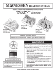
PRODUCT / FEATURES SPECIFICATIONS
*Manual Series
*Millivolt Series
Model
A
B
C
D
Model
A
B
C
D
VDY 24/18
17
13 1/2
26
16
VDY 24/18
18
13 1/2
26
16
23
1/2
24
1/2
32
16
VDY 30
13
32
16
VDY 30
13
A
D
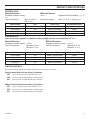
In compliance with ANS Z21.60 • CSA 2.26 and National Fuel Gas Code,
Section 6.6
C
B
Figure 1 - Minimum Hearth
Dimensions
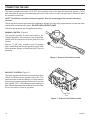
Before installing the appliance:
• Turn off gas supply to Masonry fireplace or manufactured wood
burning firebox.
Damper Stop
• Have the fireplace floor and chimney professionally cleaned to remove
ashes, soot, creosote or other obstructions. Have this cleaning performed annually after installation.
Damper
• Seal any fresh air vents or ash clean-out doors located on floor or wall
of fireplace. If not, drafting may cause pilot outage or sooting. Use a
heat-resistant sealant.
Figure 2 - Damper Stop
Installation
Install and operate the appliance as directed in this manual.
Damper stop installation:
A damper stop is provided with the unit. The damper stop must be installed as shown in (Figure 2) to prevent full
closure of the fireplace damper blade and provide a minimum flue opening, per table below.
Should the clamp not fit, or provide the required permanent opening from the table have the damper blade cut to
provide minimum permanent opening or a permanent stop installed.
Installation of this vented gas log set in the Commonwealth of Massachusetts requires the damper
be permanently removed or welded in the fully open
position. In addition, a naturally vented gas log may
not be installed in a bedroom or bathroom in the Commonwealth of Massachusetts.
Chimney
Height
VDY24/18
VDY30
6'
51 sq in
64 sq in
8'
51 sq in
64 sq in
10'
51 sq in
64 sq in
15'
39 sq in
51 sq in
20'
39 sq in
51 sq in
30'
39 sq in
51 sq in
WARNING
FOR MASSACHUSETTS RESIDENTS ONLY
The fireplace and gas logs function
as a system. If the fireplace is spilling
into the room (check with a match or
smoke stick). Reposition the damper
clamp until a positive draft is obtained,
by opening the damper. If negative
pressure in the home prevents having
a positive draft contact your dealer.
Minimum Opening Area of Chimney
Damper for Venting
32D1999
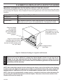
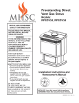
Placement in a fireplace with a restrictive barrier
Important information for the installation of this gas log set
The following are guidelines for placing a gas log set in a fireplace that has a restrictive barrier along the bottom
front opening of the fireplace. Some examples of barriers are glass/screen door frames and sunken/recessed
fireplaces.
Height of Restriction (X) Minimum Depth of Fireplace/Firebox
131/2"
15"
Any barrier greater than three inches (3") placed in front of
the gas log set is not recommended by the manufacturer.
No restriction
0 to 3"
Greater than 3"
Glass door frames
with adjustable
louvers should have
the lovers fully open
while the unit is in
operation.
The log set should be
placed against or as near
as possible to the rear wall
of the fireplace/firebox.
Height of restrictive barrier X
caused by glass door frames,
recessed fireplaces, etc. from
the base or bottom surface of the
unit. (See Table).
Depth of fireplace/firebox.
(See Table).
WARNING
Figure 3 - Reference Drawing of a Log Set in an Enclosure
Barriers such as the bottom of a glass door frame placed in front of a gas log set can
change the air flow characteristics of the fireplace which in turn can cause the unit to
overheat and malfunction. Any deviation from the installation guidelines on this sheet will
potentially void the warranty.
NOTE: Non combustible material such as refractory brick may be used to line the floor of the fireplace
in order to raise the height of the gas log set in relation to a restrictive barrier. If the unit is raised, the
minimum height dimension listed in the homeowner’s manual must not be exceeded.
NOTE: If the log set is equipped with a remote receiver, a restrictive barrier may reduce the battery life
by increasing the ambient temperature inside the fireplace. Placement of the receiver outside of the
fireplace will extend the battery life.
32D1999
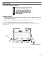
installation
warning
PLACING AND SECURING APPLIANCE
You must secure the gas log heater to
the fireplace floor. Properly securing
the grate prevents movement of
the entire unit when you adjust the
controls. Grate movement could
cause a gas leak.
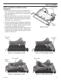
Assembly procedure
1. Center the gas log unit in the fireplace or firebox. Make certain the front feet of the grate sit inside the front
edge of the fireplace or firebox.
2. See Figure 4 for hole locations. After centering the grate correctly, mark the hole positions on the fireplace/
firebox floor. Drill two (2) 5/32" diameter holes approximately 11/2" deep.
3. Anchor the grate to the fireplace/firebox floor using the screws provided. See Figure 4.
Proper installation of the grate is essential to prevent any movement of the gas logs and controls
during operation.
Left Side
Mounting
Hole
Right Side Mounting Hole
Figure 4 - Securing Heater to Floor of Fireplace/Firebox
32D1999
A qualified gas appliance installer
must connect the appliance to the
gas supply. Consult all local codes
before installation.
Use new black iron pipe, steel pipe, copper tubing, or internally tinned copper tubing.
Copper or internally tinned copper tubing can only be used according to the National
Fuel Gas Code, section 2.6.3, providing gas meets sulfide limits, and where permitted by
local codes. Gas piping system must be sized to provide minimum inlet pressure (listed
on Data Plate) at the maximum flow rate (BTU/Hr). Undue pressure loss will occur if the
pipe is too small.
A manual shutoff valve must be installed upstream of the appliance. Union tee and
plugged 1/8" NPT pressure tapping point should be installed upstream of the appliance.
See Figure 5.
warning
caution
NOTICE
CONNECTING THE GAS
Connecting directly to an
unregulated propane/LPG tank
can cause an explosion
Pipe Coupling
To Gas Log
Regulator
Gas Supply Inlet
Manual Shutoff
Valve
Pipe
Locations that the Pressure Tapping
Point May be Installed
Figure 5 - Gas Connection
IMPORTANT: Hold appliance regulator firmly with a wrench to prevent movement when connecting to inlet piping.
Check gas type: The gas supply must be the same as stated on the gas logs rating plate. If the gas supply is
different, DO NOT INSTALL THE GAS LOGS. Contact your dealer for the correct model.
Always use an external regulator for all propane/LPG gas logs only, to reduce the supply tank pressure to a maximum of 13" W.C. This is in addition to the regulator fitted to the gas log set. High pressure natural gas systems
require a regulator to reduce supply pressure to 10" W.C.
32D1999
CONNECTING THE GAS
The heater gas inlet connection is 3/8" NPT at the regulator, inlet on the right side facing the gas log. If a left
side connection is required, the connecting pipe may be led under the rear of the gas logs or behind the grate
for connection to the inlet.
NOTE: The millivolt valve has an internal regulator, thus the incoming gas line connects directly to
the valve.
Test all gas joints from the gas meter to the appliance regulator for leaks using a gas analyzer or soap and water
solution after completing connection. DO NOT USE AN OPEN FLAME.
Check the gas pressure with the appliance burning.
Manual Control (Figure 6)
The pressure regulator is preset and locked to discourage tampering. If the pressure is not as specified,
replace with the correct part from the parts list in this
manual.
Remove 1/8" NPT plug, located on side of regulator
body. Install fitting and tubing to pressure gauge. After
taking pressure reading, re-install test plug. Check for
gas leaks.
Test Plug
Figure 6 - Pressure Test Point Location
Millivolt Control (Figure 7)
The valve regulator controls the burner pressure which
should be checked at the pressure test point. Turn
captured screw counter clockwise 2 or 3 turns and then
place tubing to pressure gauge over test point (Use test
point labeled “OUT”). After taking pressure reading, be
sure and turn captured screw clockwise firmly to re-seal.
Do not over torque. Check for gas leaks.
Test Port
“Out”
Figure 7 - Pressure Test Point Location
10
32D1999
warning
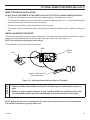
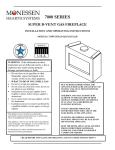
ELECTRICAL WIRING (Millivolt)
Label all wires prior to disconnection
when servicing controls. Wiring
errors can cause improper and
dangerous operation. Verify proper
operation after servicing.
THTP
Millivolt
Valve
Pilot
TP
TH
Figure 8 - Wiring Diagram
Switch
Optional Wall Switch or
Remote Receiver
The Millivolt (thermopile) is a self powered combination gas control that does not require 110VAC to operate. See
Figure 8 and installation instructions provided with optional wall switch or remote control for wiring instructions.
A maximum length of 15 feet of 18awg two conductor wire is to be used for wall switch. Note switches must be
suitable for millivolt operation.
Checking System Operation
The millivolt system and individual components may be checked with a millivolt
meter having a 0-1000MV range. Conduct
each check shown in chart below by connection meter test leads to terminals as
indicated.
TO TEST
CONNECT
METER LEADS
TO TERMINALS
METER
READING
SHOULD BE
A
COMPLETE
SYSTEM
TH & THTP
MINIMUM
100mV
B
THERMOPILE
OUTPUT
TP & THTP
MINIMUM
325mV
CHECK
TEST
A. Complete Millivolt System Check
("A" Reading - contacts CLOSED - Control Knob "ON" - Main burner should be come
ON)
a. If the reading is more than 100 millivolts and the automatic valve still does not come on - replace the control.
b. If the closed circuit reading (“A” reading) is less than 100 millivolts, determine cause for low reading - proceed as follows:
B. Thermopile Output Reading Check
(“B” Reading - contacts OPEN - Main burner OFF)
a. 325 millivolts minimum. If the minimum millivolt reading is not obtainable, readjust pilot for maximum millivolt output. If millivolt reading is still below minimum specified, replace thermopile.
32D1999
11
LOG PLACEMENT
LOG PLACEMENT
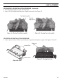
IMPORTANT: Remove logs, handling carefully by holding gently at each end. Gloves are recommended to prevent
skin irritation from ceramic fibers. If skin becomes irritated, wash gently with soap and water.
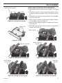
Duzy II VDY24/18D2A Log Installation Sequence:
1. Install the rear log (#1) on the two locating pins of
base. See Figure 9. Visually check to verify the log
is securely placed on the pins and in contact with the
grate. See Figure 10.
2. Install the right log (#2) on top of the control cover.
Slide the log back until touching the rear log (#1).
Visually check to verify the log is resting on the grate
and control cover. See Figure 11.
3. Install the left log (#3) with its bottom groove resting
on the right side of the grate bar. Slide the log back
until touching the rear log (#1). Visually check to verify
the log is resting on the grate. See Figure 12.
4. Install the top log (#4) with the base sitting on the
rear log (#1) and the top sitting on log (#4). Visually
check to verify the log is resting on the rear log (#1)
and left log (#3). See Figure 13.
Locator
Pins
Control
Cover
Figure 9 - Base
Rear Log
(#1)
Right Log
(#2)
Figure 10 - Placing Rear Log (#1)
Figure 11 - Placing Right Log (#2)
Top Log (#4)
Left Log (#3)
Bottom
Groove
Figure 12 - Placing Left Log (#3)
12
Figure 13 - Placing Top Log (#4)
32D1999
LOG PLACEMENT
Duzy II VDY30D2A Log Installation
Sequence:
Locator Pins
1. Install the rear log (#1) on the two locating pins of
base. See Figure 14. Visually check to verify the log
is securely placed on the pins and in contact with the
grate. See Figure 15.
2. Install the right log (#2) on top of the control cover.
Slide the log back until touching the rear log (#1).
Visually check to verify the log is resting on the grate
and control cover. See Figure 16.
3. Install the left log (#3) with its bottom groove resting on
the right side of the grate bar. Slide the log back until
touching the rear log (#1). Visually check to verify the
log is resting on the grate. See Figure 17.
4. Install the top log (#4) with the base sitting on the rear
log (#1) and the top sitting on log (#4). Visually check
to verify the log is resting on the rear log (#1) and left
log (#3). See Figure 18.
Figure 14 - Base
Rear Log
(#1)
Control
Cover
Right Log
(#2)
Figure 15 - Placing Rear Log (#1)
Left Log (#3)
Figure 16 - Placing Right Log (#2)
Top Log (#4)
Bottom
Groove
Figure 17 - Placing Left Log (#3)
32D1999
Figure 18 - Placing Top Log (#4)
13
LOG PLACEMENT
VDY24/18D3R Log Installation
Sequence:
Pins
1. Line up pins on bottom of Rear Log #1 with pins on
grate bar and place on grate. See Figures 19 and
20.
2. Place Front Left Log #2 on left front of grate bar lining
up cutout in bottom of log with grate bar. See Figure
21. 3. Place Front Right Log #3 on right front of grate bar
lining up cutout in bottom of log with grate bar. Make
sure Log #3 touches Log #1. See Figure 22.
4. Place back end Top Middle Log #4 on Log #1. Press
the side of Log #4 up against raised area of Log #1.
Line up notch in front end of #4 with grate bar. See
Figure 23.
Rear Log
(#1)
Figure 20 - Placing Rear Log on Base (#1)
Front Right Log (#3)
Cutout
Control
Cover
Figure 19 - Base
Cutout
Front Left Log (#2)
Figure 21 - Placing Front Left Log (#2)
Top Middle
Log (#4)
Notch
Figure 22 - Placing Front Right Log (#3)
14
Figure 23 - Placing Top Middle Log (#4)
32D1999
LOG PLACEMENT
VDY24/18D3R LOG Installation Sequence (Continued)
5. Rest Top Right Log #5 on Log #3. See Figure 24.
6. Line up Top Left Log #6 with notches on Log #2 and Log #4. See Figure 25.
Top Right Log (#5)
Top Left
Log (#6)
Figure 24 - Placing Top Right Log (#5)
Figure 25 - Placing Top Left Log (#6)
VDY30D3R LOG Installation Sequence:
1. Line up pins on bottom of Rear Log #1 with pins on grate bar and place on grate. See Figures 26 and 27.
Locator Pins
Control Cover
Rear Log
(#1)
Figure 27 - Placing Rear Log
Figure 26 - Base
32D1999
15
LOG PLACEMENT
VDY30D3R LOG Installation Sequence (Continued)
2. Place Front Left Log #2 on left front of grate bar lining
up cutout in bottom of log with grate bar. See Figure
28. 3. Place Front Right Log #3 on right front of grate bar
lining up cutout in bottom of log with grate bar. Make
sure Log #3 touches Log #1. See Figure 29.
4. Place back end Top Middle Log #4 on Log #1. Press
the side of Log #4 up against raised area of Log #1.
Line up notch in front end of #4 with grate bar. See
Figure 30.
5. Rest Top Right Log #5 on Log #3. See Figure 31.
6. Line up Top Left Log #6 with notches on Log #2 and
Log #4. See Figure 32.
Front Left Log (#2)
Figure 28 - Placing Front Left Log (#2)
Top Mid Log (#4)
Front Right Log (#3)
Figure 29 - Placing Front Right Log (#3)
Top Right Log (#5)
Figure 31 - Placing Top Right Log (#5 )
16
Figure 30 - Placing Top Mid Log (#4)
Top Left Log (#6)
Figure 32 - Placing Top Left Log (#6 )
32D1999
LOG PLACEMENT
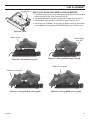
VDY24/18D4 Log Installation Sequence:
Bottom Front Log (#2)
Figure 33 - Placing Front Log (#2)
Locator Pins
1. Place Bottom Front Log (#2) on front of grate. See Figure
33.
2. Place Back Log (#1) on back of grate lining up two (2) pins
on grate with holes in bottom of log. See Figures 34 and
35.
3. Place Left Top Log (#3) on left end of Bottom Front and Back
Logs. See Figure 36.
4. Place Center Crossover Log (#4) across middle of Bottom
Front and Back Logs. See Figure 37.
5. Place Left Top Crossover Log (#5) up against Left Top Log.
See Figure 38.
6. Rest Right Top Log (#6) on Center Crossover Log and front
of grate. See Figure 39
Back Log (#1)
Figure 34 - Base
Top Left Log (#3)
Figure 36 - Placing Left Top Log (#3)
Left Crossover
Top Log (#5)
Figure 38 - Placing Left Top Log (#5)
32D1999
Figure 35 - Placing Back Log (#1)
Center Crossover
Log (#4)
Figure 37 - Placing Center Log (#4)
Right Top
Log (#6)
Figure 39 - Placing Right Top Log (#6)
17
LOG PLACEMENT
Bottom Front Log (#2)
Figure 40 - Placing Front Log (#2)
Locator Pins
VDY30D4 Log Installation Sequence:
1. Place Bottom Front Log (#2) on front of grate. See Figure 40.
2. Place Back Log (#1) on back of base lining up two (2) pins on base with holes
in bottom of log. See Figures 41 and 42.
3. Place Left Top Log (#3) on left end of Bottom Front and Back Logs. See
Figure 43.
4. Place Center Crossover Log (#4) across middle of Bottom Front and Back
Logs. See Figure 44.
5. Place Left Top Crossover Log (#5) up against Left Top Log. See
Figure 45.
6. Rest Right Top Log (#6) on Center Crossover Log and front of grate. See
Figure 46.
7. Place Small Front Log (#7) between Center Crossover Log and Top Left Log.
See Figure 47.
Top Left Log (#3)
Figure 41 - Base
Back Log (#1)
Figure 43 - Placing Left Top Log (#3)
Figure 42 - Placing Back Log (#1)
Center Crossover Log (#4)
Left Crossover Top
Log (#5)
Figure 45 - Placing Left Top Log (#5)
Figure 44 - Placing Center Log (#4)
Right Top Log (#6)
Small Front Log (#7)
Figure 46 - Placing Right Top Log (#6)
18
Figure 47 - Placing Small Front Log (#7)
32D1999
LOG PLACEMENT
Locator Pins
DUZY5 LOG VDY24/18D5 Installation SEQUENCE:
1. Place Back Log (#1) on back of base lining up two (2) pins on base with
holes in bottom of log. See Figures 48 and 49.
2. Placed Bottom Right Log (#2) on right side of grate. See Figure 50.
3. Place Bottom Left Log (#3) on left side of grate. See Figure 51.
4. Place one end of Middle Left Log (#4) on Bottom Left Log. Rest other
end of Middle Left Log (#4) behind Middle Right Log. See Figure 52.
Figure 48 - Base
Back Log (#1)
Figure 49 - Placing Back Log (#1)
Bottom Right
Log (#2)
Figure 50 - Placing Bottom Right Log (#2)
Middle Left Log (#4)
Bottom Left Log (#3)
Figure 51 - Placing Bottom Left Log (#3)
32D1999
Figure 52 - Placing Middle Left Log (#4)
19
LOG PLACEMENT
DUZY5 LOG VDY24/18D5 Installation SEQUENCE (continued):
5. Place Middle Right Log (#5) on top of Bottom Right Log. See Figure 53.
6. Rest Top Right Log (#6) on Back Log and Bottom Right Log. See Figure 54.
7. Place Top Left Log (#7) on Bottom Left Log. See Figure 55.
8. Place Front Middle Log (#8) between the first and second prongs. See Figure 56.
Top Right Log (#6)
Middle Right Log (#5)
Figure 53 - Placing Middle Right Log (#5)
Top Left Log (#7)
Figure 55 - Placing Top Left Log (#7)
20
Figure 54 - Placing Top Right Log (#6)
First Prong
Second
Prong
Figure 56 - Placing Front Middle Log (#8)
32D1999
LOG PLACEMENT
VDY30D5 Log Installation Sequence:
1. Place Back Log (#1) on back of base lining up two (2)
pins on base with holes in bottom of log. See Figures
57 and 58.
2. Place Bottom Right Log (#2) on right side of grate in
front of back log. See Figure 59. 3. Place Bottom Left Log (#3) on left side of grate in front
of back log. See Figure 60.
4. Place Middle Left Log (#4) on top of bottom left log.
See Figure 61.
Locator
Pins
Figure 57 - Base
Back Log (#1)
Figure 58 - Placing Back Log (#1)
Bottom Right Log (#2)
Figure 59 - Placing Bottom Right Log (#2)
Middle Left Log (#4)
Bottom Left Log (#3)
Figure 60 - Placing Bottom Left Log (#3)
32D1999
Figure 61 - Placing Middle Left Log (#4)
21
LOG PLACEMENT
VDY30D5 Log Installation Sequence (Continued)
5. Place Middle Right Log (#5) on top of bottom right log. See Figure 62.
6. Place Top Right Log (#6) on middle right log and back log. See Figure 63.
7. Place Top Left Log (#7) on bottom left log and middle left log. See Figure 64.
8. Place Middle Front Log (#8) between second and third grate bars. See Figure 65.
Middle Right Log (#5)
Figure 62 - Placing Middle Right Log (#5)
Top Left Log (#7)
Figure 64 - Placing Middle Right Log (#7)
22
Top Right Log (#6)
Figure 63 - Placing Top Right Log (#6)
Middle Front Log (#8)
Figure 65 - Placing Middle Front Log (#7)
32D1999
FIREPLACE DRAFT TEST
Placement of the Glowing Embers
Cover the burner pan with glowing embers (rock wool) provided. Tear pieces approximately 1/2" in size (roughly
the size of a nickel) and cover the burner evenly.
DO NOT…
1. Pile the rock wool too thickly on pan.
2. Place rock wool higher than the top of the front grate bar.
3. Cover the pilot with rock wool.
Placement of Decorative Volcanic Rock
Sprinkle volcanic rock in front of front glowing embers and to both sides. DO NOT SPRINKLE ON BURNERS,
PILOT OR LOGS.
IMPORTANT: FIREPLACE DRAFT TEST DURING INITIAL INSTALLATION
It is critical to verify that your chimney is drafting properly because the fireplace and gas logs function as a system.
WARNING
Although MHSC goes to great lengths to design vented gas log sets that minimize sooting, all vented log sets will
soot over time. Sooting normally appears as areas of a black powder-like substance on the logs. It is important
to periodically clean and inspect the logs per the cleaning and servicing section of the manual.
Fireplace systems that do not draft properly can increase the amount of soot produced
by normal operation of the log set and in extreme cases can cause soot to be deposited
within the room. This effect can be a sign of a blocked chimney, a faulty vent system or
the result of negative pressure within the home. The dealer should be able to diagnose if a
problem exists and be able to provide a solution to improve the venting of the fireplace.
FIREPLACE DRAFT TEST METHOD
To determine if your fireplace is drafting properly, turn the log set on. After the log set has been burning for about
10 minutes, place a match or smoke stick along the top and sides of the fireplace opening. If the flame or smoke
is not pulled into the fireplace, then the fireplace is not venting properly. At this point the damper stop should
be adjusted so that the damper opening is increased. If the problem remains after the open area of the damper
is increased, then the fireplace system should be professionally inspected to determine if your firebox/chimney
is venting properly.
32D1999
23
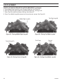
FLAME APPEARANCE
Checking Burner Flames
In normal operation at full rate after approximately 15 minutes, the following flame appearance should be observed.
Rear flame should be yellow and extend
vertically. Maximize spacing on top logs.
Burner flame should become yellow as they
contact embers on the face of the log. The log
face will glow a bright reddish orange.
Ember bed should be yellow/orange glow.
Figure 66 - Proper Flame Height
Manual and Millivolt Control with Pilot Only
Pilot Flame Appearance
The pilot flame must always be present when appliance is in operation. It should touch the thermocouple or
thermopile body.
Thermocouple
Thermopile
Figure 67 - Manual Control Pilot
Figure 68 - Millivolt Control Pilot
Initial Startup
During manufacturing, fabricating and shipping, various components of this appliance are treated with certain
oils, films or bonding agents. These chemicals are not harmful, but may produce annoying smoke and smells as
they are burned off during the initial operation of the appliance. The initial break-in operation should last 2-3 hours
with the burner at the highest setting. The appliance must not be used with glassed doors in the closed position.
This can result reduced combustion and overheating.
24
32D1999
OPERATING INSTRUCTIONS
SAFETY INSTRUCTION FOR MANUAL AND Millivolt CONTROL WITH PILOT
for your safety read before lighting
warning
A. This appliance is equipped with an ignition device which automatically lights the pilot.
B. BEFORE OPERATING smell all around the appliance area for gas. Be sure to smell next to the
floor because some gas is heavier than air and will settle on the floor.
WHAT TO DO IF YOU SMELL GAS:
• Do not attempt to light any appliance.
If you do not follow these instruction
• Do not touch any electric switch; do not
exactly, a fire or explosion may result
use any phone in your building.
causing property damage, personal injury
• Immediately call your gas supplier from a
or loss of life.
neighbor's phone. Follow the gas supplier's instructions.
• If you cannot reach your gas supplier, call the fire department.
C. Use only your hand to push in, or turn the gas control knob. Never use tools. If the knob will not
push in or turn by hand, don't try to repair it. Call a qualified service technician. Force or attempted
repair may result in a fire or explosion.
D. Do not use this appliance if any part of it has been under water. Immediately call a qualified service technician to inspect the appliance and to replace any part of the control system and any gas
control that has been under water.
MANUAL CONTROL LIGHTING INSTRUCTIONS
1. STOP! Read the safety information label.
2. Make sure the manual shutoff valve is fully open.
3. This gas log set is equipped with an ignition device (piezo) which automatically lights the pilot. If
piezo ignitor does not light the pilot, see instructions for “Match Lighting Instructions,” page 26.
4. Push in gas control knob slightly and turn clockwise
to “OFF.”
NOTE: Knob cannot be turned to “OFF” unless knob is pushed
in slightly.
5. Wait five (5) minutes to clear out any gas. Then smell for gas, including near the
floor. If you smell gas, STOP! Follow “B” in the safety information label. If you
don’t smell gas, go to next step.
6. Find pilot - follow metal tube from gas control.
Figure 69 7. From “OFF” position, push in gas control knob slightly and turn counterclockwise
Control Knob
to “PILOT.” Push in control knob for 5 seconds.
8. With the control knob pushed in, immediately light the pilot by depressing the
piezo and releasing. Continue to hold the control knob in for about one (1) minute
after the pilot is lit. Release knob and it will pop back up. Pilot should remain lit.
If it goes out, repeat steps 5 through 9.
• If knob does not pop up when released, stop and immediately call your service
technician or gas supplier.
Figure 70 • If the pilot will not stay lit after several tries, turn the gas control knob to off
Manual Pilot
and call you service technician or gas supplier.
9. Turn gas control knob counterclockwise
to “ON.”
TO TURN OFF GAS TO APPLIANCE
1. Push in gas control knob slightly and turn clockwise
32D1999
to "OFF". Do not force.
25
operating instructions
Millivolt CONTROL LIGHTING INSTRUCTIONS
warning
1. STOP! Read the safety information label.
2. Make sure the manual shutoff valve is fully open.
3. This gas log set is equipped with an ignition device (piezo) which automatically lights the pilot. If piezo
ignitor does not light the pilot, see instructions for Match Lighting below.
4. Turn gas control knob clockwise
to the “OFF” position, and turn ON/OFF switch to
“OFF” position.
5. Wait (5) minutes to clear out any gas. Then smell for gas, including near the floor. If you smell gas,
STOP! Follow “B” in the safety information label. If you don't smell gas, go to next step.
6. From “OFF” position, turn the gas control knob counterclockwise
to “IGN” position. Push in
control knob for 5 seconds.
7. With the control knob pushed in, push in and release the piezo ignitor button to light the pilot.
8. Continue pushing the control knob in for a further 60 seconds to prevent the flame detector from shutting off the gas while the probe is warming up. Release the control knob.
9. Turn gas control knob counterclockwise
to the “ON” position.
10. After the pilot has been lit for one minute, the burners can be turned on. Turn the ON/OFF switch to
“ON” position.
11. If the gas logs will not operate, follow the
instructions To Turn Off Gas To Appliance,
page 25 and call your service technician or
Wait 30 seconds before readjusting the
gas supplier.
heater when the control knob has been
Figure 71 - Millivolt Pilot
turned down to a lower setting.
Figure 72 - Control Knob
Figure 73 - On/Off Switch
TO TURN OFF GAS TO HEATER
1. Turn control knob clockwise
to “OFF” position to completely shut off the heater.
2. If applicable: Turn ON/OFF switch to “OFF” position.
3. If applicable: Turn off all electric power to the heater.
MATCH LIGHTING INSTRUCTIONS
1. Remove any items necessary for easy access to the pilot (for example: logs, screens, etc.).
2. Follow appropriate lighting instructions found previously. Instead of pushing and releasing the piezo button, light a match and hold the flame to the end of the pilot and ignite the pilot.
3. After control knob has been released and pilot stays lit, re-install any items that were removed for
pilot access.
4. Call a qualified service technician for repair or replacement of the piezo ignitor.
26
32D1999
optional remote receiver (millivolt)
remote receiver installation
Do not place the remote in the fireplace if any of the following conditions apply:
•
The floor of the fireplace is recessed below the fireplace opening. See Warnings on Page 7.
•
The fireplace has glass doors which when open reduces the opening width to 11/2" or more below the stated
minimum dimensions within the homeowner’s manual.
•
The floor of the fireplace is sheet metal without a brick covering.
•
The remote receiver is attached but does not physically fit inside the fireplace with 2" clearance to the side
wall.
installing remote receiver
Connect wires according to remote receiver instructions. The female terminals should be connected to factory
attached male terminals which are located on right hand side of the burner. See Figure 74.
NOTE: Do not let wires touch grate and/or burner.
For more details, see remote receiver instructions.
THTP
Pilot
Millivolt
Valve
TH
TP
Optional Wall Switch or
Remote Receiver
NOTICE
Figure 74 - Attaching Remote Receiver Wires to Terminals
• Failure to follow instructions exactly will void warranty and could cause receiver to
melt.
• Failure to place remote receiver in any location within the fireplace other than
recommended location will void warranty and could cause receiver unit to melt.
NOTE: Battery life decreases as temperature increases. Keep remote receiver in a low temperature
area outside of fireplace to prolong battery life.
32D1999
27
WARNING
CLEANING and SERVICING
Turn off gas logs and allow to cool
before cleaning. Disconnect electrical
power if applicable before cleaning or
servicing.
Remove logs, handling carefully by holding gently at each end. Gloves are recommended to prevent skin irritation from ceramic fibers. If skin becomes irritated, wash gently with soap and water. See manual for correct
log placement.
Periodic Cleaning - See parts diagram for location of items discussed below.
• Do not use cleaning fluid to clean logs or any part of gas logs.
• Logs - brush with soft bristle brush or vacuum with brush attachment.
• Vacuum loose particles and dust from the control and grate weldment.
• Inspect and clean burner air intake holes. Remove lint or particles with vacuum or brush. Failure to keep air
intake holes clean will result in sooting and poor combustion.
• If embers (rock wool) have turned a rust color and become brittle, remove old embers (rock wool) from log
set. Replace with new rock wool. Rock wool can be purchased from your local dealer. See log placement
section for placement of embers.
Annual Cleaning/Inspection - See parts diagram for location of items discussed
below.
• Inspect and clean all burner ports.
• Verify burner and pilot flame pattern and log placement for proper operation.
• Verify smooth and responsive ignition of burner.
• Inspect and clean chimney.
• Inspect and clean burner air intake holes. Remove lint or particles with vacuum or brush. Failure to keep air
intake holes clean will result in sooting and poor combustion.
28
32D1999
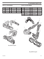
Illustrated parts list
Duzy (II) Logs Series
Item Description
Duzy (III) Logs Series
Qty. VDY24/18D2
1
Rear Log
1
32D0400
2
Right Log
1
3
Left Log
1
4
Top Log
1
VDY30D2
Item Description
Qty. VDY24/18D3R VDY30D3R
32D0410
1
Rear Log
1
32D2118
32D2124
32D0401
32D0411
2
Front Left Log
1
32D2117
32D2123
32D0402
32D0412
3
Front Right Log
1
32D2116
32D2122
32D0403
32D0413
4
Top Middle Log
1
32D2114
32D2120
5
Top Right Log
1
32D2113
32D2119
6
Top Left Log
1
32D2115
32D2121
4
6
4
3
5
2
2
3
1
1
Duzy VDYD2 Log Set
Duzy VDYD3 Log Set
32D1999
29
Illustrated parts list
Duzy (IV) Logs Series
Item
Description
Qty
VDY24/18D4
VDY30D4
1
Back Log
1
32D3101
32D3111
2
Bottom Front Log
1
32D3102
32D3112
3
Top Left Log
1
32D3103
32D3113
4
Center Crossover Log
1
32D3104
32D3114
5
Left Top Crossover Log
1
32D3105
32D3115
6
Right Top Log
1
32D3106
32D3116
7
Small Front Log
1
—
32D3117
7
3
4
1
6
2
5
30
32D1999
Illustrated parts list
Duzy (V) Logs Series
Item
Qty
VDY24/18D5
1
Description
Back Log
1
32D3121
2
Bottom Right Log
1
32D3122
3
Bottom Left Log
1
32D3123
4
Middle Left Log
1
32D3124
5
Middle Right Log
1
32D3125
6
Top Right Log
1
32D3126
7
Top Left Log
1
32D3127
8
Front Middle Log
1
32D3128
3
1
4
5
6
2
8
7
Duzy (V) Logs Series
Item
1
2
3
4
5
6
7
8
Description
Back Log
Bottom Right Log
Bottom Left Log
Middle Left Log
Middle Right Log
Top Right Log
Top Left Log
Middle Front Log
Qty
1
1
1
1
1
1
1
1
VDY30D5
32D3131
32D3132
32D3133
32D3134
32D3135
32D3136
32D3137
32D3138
1
3
2
7
4
6
8
5
32D1999
31
Illustrated parts list
24/18 Model
Item Description
VDY24/18
NMP
VDY24/18
PMP
VDY24/18
NVP
VDY24/18
PVP
1
Main Injector
32D0100
32D0118
32D0100
32D0507
2
Control Knob
27D0602
27D0602
18D0603
18D0603
3
Manual Control Valve
with Pilot
27D8951
27D8951
N/A
N/A
4
Millivolt Control Valve
with Pilot
N/A
N/A
27D8006
27D8005
5
Pilot
27D8972
27D8971
27D8974
27D8973
6
Thermocouple/
Thermopile
28D0400
28D0400
26D0566
26D0566
7
Regulator
24D0305
24D0306
N/A
N/A
VDY30
NMP
VDY30
PMP
VDY30
NVP
VDY30
PVP
1
2
3
30 Model
Item Description
1
Main Injector
32D0090
32D0113
32D0090
32D0117
2
Control Knob
27D0602
27D0602
18D0603
18D0603
3
Manual Control Valve
with Pilot
27D8951
27D8951
N/A
N/A
4
Millivolt Control Valve
with Pilot
N/A
N/A
27D8006
27D8005
5
Pilot
27D8972
27D8971
27D974
27D8973
6
Thermocouple/
Thermopile
28D0400
28D0400
26D0566
26D0566
7
Regulator
24D0305
24D0306
N/A
N/A
4
Accesories
Flex Connector
Flexcon30
All Models
Wall Kit Switch (w/20' wire)
MVWS
Millivolt
On/Off Remote Control KIts
RCB, RCM, TLM, WWTD
Millivolt
Remote Receiver Cover - Embers
RRCE
Millivolt
Remote Receiver Cover - Metal
RRCM
Millivolt
Volcanic Rock
VR1000A
All Models
Decorative Ceramic Fiber Embers
EMBERS
All Models
Ceramic Fiber Cinders
CINDERS
All Models
Rock Wool
DV-RWA
All Models
32
6
5
7
32D1999
WARNING
TROUBLESHOOTING
Turn appliance OFF and allow to cool
before servicing. Only a qualified
service person should service and
repair the heater.
Note: All troubleshooting items are listed in order of operation.
OBSERVED PROBLEM
POSSIBLE CAUSE
REMEDY
When ignitor button
is pressed, there is no
spark at pilot.
1. Ignitor electrode positioned
wrong.
2. Ignitor electrode is broken.
3. Ignitor electrode not connected
to ignitor cable.
4. Ignitor cable pinched or wet. Keep
ignitor cable dry.
5. Broken ignitor cable.
6. Bad piezo ignitor.
1 Replace ignitor.
2. Replace ignitor.
3. Reconnect ignitor cable.
Appliance produces
unwanted odors.
1. Appliance burning vapors from
paint, hair spray, glues, etc.
2. Gas leak.
3. Fireplace Spilling
1. Ventilate room. Stop using odor causing
products while heater is running.
2. Locate and correct all leaks.
3. Check fireplace, adjust damper position to
eliminate spillage (backdraft)
Appliance shuts off during use.
1. Low line pressure.
2. Pilot is partially clogged.
3. Defective Thermopile.
1. Locate and correct all leaks.
2. Replace control valve.
Gas odor even when
control knob is in OFF
position.
1. Gas leak.
2. Control valve defective.
1. Locate and correct all leaks.
2. Replace control valve.
When ignitor button is
pressed, there is spark at
pilot, but no ignition.
1. Gas supply turned off or manual
shutoff valve closed.
2. Control knob not in PILOT position.
3. Control knob not pressed in while in
PILOT position.
4. Air in gas lines when installed.
5. Pilot is clogged.
6. Gas regulator setting is not correct.
1. Turn on gas supply or open manual shutoff
valve
.
2. Turn control knob to PILOT position.
3. Press in control knob while in
PILOT position.
4. Continue holding down control knob. Repeat
igniting operation until air is removed.
5. Replace pilot assembly or get it serviced.
6. Replace gas regulator
Pilot lights, but flame
goes out when control
knob is released.
1. Control knob not fully pressed in.
2. Control knob not pressed in long
enough.
3. Manual shutoff valve not fully open.
1. Press in control knob fully.
2. After pilot lights, keep control knob pressed
in for 30 seconds.
3. Fully open manual shutoff valve.
32D1999
4. Free ignitor cable if pinched by any metal or
tubing.
5. Replace ignitor cable.
6. Replace piezo ignitor.
33
TROUBLESHOOTING
OBSERVED PROBLEM
POSSIBLE CAUSE
REMEDY
One or both burners do
not light after pilot is lit.
1. Burner orifice is clogged or damaged.
2. Burner is damaged.
3. Gas regulator defective.
1. Clean burner or replace burner orifice.
2. Replace burner orifice.
3. Contact qualified service person.
Burner backfires during
combustion.
1. Manifold pressure is too low.
2. Burner orifice is clogged.
1. Contact local gas company.
2. Clean burner or replace burner orifice.
Slight smoke or odor dur- 1. Burner orifice is clogged or daming initial operation.
aged.
2. Burner is damaged.
3. Gas regulator defective.
1. Clean burner or replace burner orifice.
2. Replace burner.
3. Replace gas regulator.
Logs appear to smoke
after initial operation.
1. Vapors from paint or curing process
of logs.
1. Problem will stop after a few hours of operation.
1. Log is intended to be smokeless. Turn OFF
heater and call qualified service person.
Heater produces a whistling noise when burner
is lit.
1. Turning control knob to HIGH position when burner is cold.
2. Air in gas line.
1. Turn control knob to ON position and let
warm up for a minute.
2. Operate burner until air is removed from line.
Have gas line checked by local gas company.
3. Clean burner or replace burner orifice.
3. Dirty or partially clogged burners orifice.
1. LP-regulator shut down due to inlet
pressure too high.
WARNING
No gas to pilot.
34
1. Verify LP tank regulator is installed and set
at 11" to 13" W.C.
2. Replace regulator on heater.
If the gas quality is bad, your pilot
may not stay lit, the burners may
produce soot and the heater may
backfire when lit. If the gas quality or
pressure is low, contact your local gas
supplier immediately.
32D1999
Massachusetts Residents Only — Please read and follow these special requirements
NOTE REGARDING VENTED PRODUCTS
This product must be installed by a licensed plumber or gas fitter
when installed within the Commonwealth of Massachusetts.
Any residence with a direct vent product must have a CO
detector installed in the residence.
Installation of the fireplace or vented gas log in the State of
Massachusetts requires the damper to be permanently removed
or welded in the fully open position.
In addition, a naturally vented gas log may not be installed in a
bedroom or bathroom in the State of Massachusetts.
Flex line installation must not exceed 36 inches and must have
a T shutoff valve.
NOTE REGARDING VENT FREE PRODUCTS
This product must be installed by a licensed plumber or gas fitter
when installed within the Commonwealth of Massachusetts.
In addition, vent free products may not be installed in a
bedroom or bathroom regardless of size or type in the State of
Massachusetts.
Flex line installation must not exceed 36 inches and must have
a T shutoff valve.
CARBON MONOXIDE DETECTOR REQUIREMENTS
(2)Revise 10.8.3 by adding the following additional
requirements:
(a) For all side wall horizontally vented gas fueled
equipment installed in every dwelling, building or structure used
in whole or in part for residential purposes, including those
owned or operated by the Commonwealth and where the side
wall exhaust vent termination is less than seven (7) feet above
finished grade in the area of the venting, including but not
limited to decks and porches, the following requirements shall
be satisfied:
1. Installation of carbon monoxide detectors. At the time
of installation of the side wall horizontal vented gas fueled
equipment, the installing plumber or gas fitter shall observe
that a hard wired carbon monoxide detector with an alarm and
battery back-up is installed on the floor level where the gas
equipment is to be installed. In addition, the installing plumber
or gas fitter shall observe that a battery operated or hard wired
carbon monoxide detector with an alarm is installed on each
additional level of the dwelling, building or structure served by
the side wall horizontal vented gas fueled equipment. It shall be
the responsibility of the property owner to secure the services of
qualified licensed professionals for the installation of hard wired
carbon monoxide detectors
a. In the event that the side wall horizontally vented gas
fueled equipment is installed in a crawl space or an attic, the
hard wired carbon monoxide detector with alarm and battery
back-up may be installed on the next adjacent floor level.
b. In the event that the requirements of this subdivision
can not be met at the time of completion of installation, the
owner shall have a period of thirty (30) days to comply with the
above requirements; provided, however, that during said thirty
(30) day period, a battery operated carbon monoxide detector
with an alarm shall be installed.
32D1999
2. Approved Carbon Monoxide Detectors. Each carbon
monoxide detector as required in accordance with the above
provisions shall comply with NFPA 720 and be ANSI/UL 2034
listed and IAS certified.
3. Signage. A metal or plastic identification plate shall be
permanently mounted to the exterior of the building at a
minimum height of eight (8) feet above grade directly in line with
the exhaust vent terminal for the horizontally vented gas fueled
heating appliance or equipment. The sign shall read, in print size
no less than one-half (1/2) inch in size, “GAS VENT DIRECTLY
BELOW. KEEP CLEAR OF ALL OBSTRUCTIONS.”
4. Inspection. The state or local gas inspector of the side wall
horizontally vented gas fueled equipment shall not approve the
installation unless, upon inspection, the inspector observes
carbon monoxide detectors and signage installed in accordance
with the provisions of 248 CMR 5.08(2)(a)1 through 4.
(b) Exemptions: The following equipment is exempt from 248
CMR 5.08(2)(a)1 through 4:
1. The equipment listed in Chapter 10 entitled "Equipment Not
Required To Be Vented" in the most current edition of NFPA 54
as adopted by the Board; and
2. Product Approved side wall horizontally vented gas fueled
equipment installed in a room or structure separate from the
dwelling, building or structure used in whole or in part for
residential purposes.
(c) Manufacturer requirements — Gas Equipment Venting
System Provided. When the manufacturer of Product
Approved side wall horizontally vented gas equipment provides
a venting system design or venting system components with
the equipment, the instructions provided by the manufacturer
for installation of the equipment and the venting system shall
include:
1. Detailed instructions for the installation of the venting system
design or the venting system components; and
2. A complete parts list for the venting system design or venting
system.
(d) Manufacturer requirements — Gas Equipment Venting
System Not Provided. When the manufacturer of a Product
Approved side wall horizontally vented gas fueled equipment
does not provide the parts for venting the flue gases, but
identifies “special venting systems,” the following requirements
shall be satisfied by the manufacturer:
1. The referenced "special venting system" instructions shall
be included with the appliance or equipment installation
instructions; and
2. The “special venting systems” shall be Product Approved by
the Board, and the instructions for that system shall include a
parts list and detailed installation instructions.
(e) A copy of all installation instructions for all Product
Approved side wall horizontally vented gas fueled equipment,
all venting instructions, all parts lists for venting instructions,
and/or all venting design
35
Limited Lifetime Warranty Policy
Lifetime Warranty
The following components are warranted for life to the original owner, subject to proof of purchase:
Firebox, Combustion Chamber, Heat Exchanger, Grate and Stainless Steel Burners.
Five Year Warranty
The following components are warranted for 5 years to the original owner, subject of proof of purchase:
Ceramic Fiber Logs, Catalytic Filter and Aluminized Burners.
Basic Warranty
MHSC warrants the components and materials in your gas appliance to be free from manufacturing and
material defects for a period of two years from date of installation. After installation, if any of the components manufactured by MHSC in the appliance are found to be defective in materials or workmanship,
MHSC will, at its option, replace or repair the defective components at no charge to the original owner.
MHSC will also pay for reasonable labor costs incurred in replacing or repairing such components for
a period of two years from the date of installation. Any products presented for warranty repair must be
accompanied by a dated proof of purchase.
This Limited Warranty will be void if the appliance is not installed by a qualified installer in accordance
with the installation instructions. The Limited Lifetime Warranty will also be void if the appliance is not
operated and maintained according to the operating instructions supplied with the appliance, and does
not extend to (1) firebox/burner assembly damage by accident, neglect, misuse, abuse, alteration,
negligence of others, including the installation thereof by unqualified installers, (2) the costs of removal,
reinstallation or transportation of defective parts on the appliance, or (3) incidental or consequential
damage. All service work must be performed by an authorized service representative.
This warranty is expressly in lieu of other warranties, express or implied, including the warranty of merchantability of fitness for purpose and of all other obligations or liabilities. MHSC does not assume for it
any other obligations or liability in connection with the sale or use of the appliance. In states that do not
allow limitations on how long an implied warranty lasts, or do not allow exclusion of indirect damages,
those limitations of exclusions may not apply to you. You may also have additional rights not covered
in this Limited Warranty.
MHSC reserves the right to investigate any and all claims against the Limited Warranty and decide upon
method of settlement.
IF WARRANTY SERVICE IS NEEDED...
1. Contact your supplier. Make sure you have your warranty, your sales receipt and the model/serial
number of your MHSC product.
2. DO NOT ATTEMPT TO DO ANY SERVICE WORK YOURSELF.
MHSC
149 Cleveland Drive • Paris, Kentucky 40361
www.mhsc.com