1
Diva 2440 ADSL Router
User’s Guide
www.eicon.com
Second Edition (June 2001)
206-378-02
Diva and Eicon are either registered trademarks or trademarks of Eicon Networks Corporation.
Microsoft, Windows, and Windows NT are either registered trademarks or trademarks of Microsoft
Corporation in the United States and/or other countries.
Adobe and Acrobat are either registered trademarks or trademarks of Adobe Systems Incorporated in
the United States and/or other countries.
Apple and Macintosh are trademarks of Apple Computer, Inc. in the United States and/or other
countries.
IBM is a registered trademark of IBM Corporation in the United States and/or other countries.
All other brand and product names are trademarks or registered trademarks of their respective owners.
Changes are periodically made to the information herein; these changes will be incorporated into new
editions of the publication. Eicon Networks may make improvements and/or changes in the products
and/or programs described in this publication at any time.
If you have comments on this manual or the products it describes, address them to:
Eicon Networks Corporation
Attention: Technical Publications
9800 Cavendish Blvd.
Montreal, Quebec
Canada H4M 2V9
Eicon Networks Corporation may use or distribute whatever information you supply in any way it
believes appropriate without incurring any obligations to you.
Eicon Networks Corporation is a business unit of i-data international a-s.
Copyright © 1999-2001 Eicon Networks Corporation. All rights reserved, including those to reproduce
this publication or parts thereof in any form without permission in writing from Eicon Networks
Corporation.
Page 2
Contents
Introduction.....................................................................................................5
Introducing the Diva 2440 ADSL Router.................................................................................. 6
Package Contents.................................................................................................................... 7
Connection Scenarios.............................................................................................................. 8
How ADSL Works .................................................................................................................. 10
Setup..............................................................................................................11
Overview ................................................................................................................................
Internet Account Information..................................................................................................
Ports and Indicator Lights ......................................................................................................
Step 1: Connect the Cables ...................................................................................................
Step 2: Access the Diva 2440 Web Interface.........................................................................
Step 3: Complete the Internet Wizard....................................................................................
Optional: Installing the Diva Assistant....................................................................................
Connecting a Second Computer............................................................................................
LAN Setup .............................................................................................................................
TCP/IP Setup .........................................................................................................................
Troubleshooting......................................................................................................................
Connecting a Phone to the Pass-through Phone Port ...........................................................
About Microfilters ...................................................................................................................
Technical Support ..................................................................................................................
12
13
14
16
18
19
21
23
24
27
31
32
33
34
Using your Diva 2440 ...................................................................................35
General Information ...............................................................................................................
Resetting the Device..............................................................................................................
Starting the Web-based Configuration Interface....................................................................
Configurations – Saving, Restoring, and Resetting ...............................................................
Upgrading Firmware ..............................................................................................................
Login Password and other Security Features ........................................................................
About the Diva Assistant........................................................................................................
36
37
38
40
41
43
45
Advanced Topics..........................................................................................47
Virtual Private Networking .....................................................................................................
Network Address Translation .................................................................................................
Command Line Interface (CLI)...............................................................................................
Using TFTP to Transfer Files .................................................................................................
48
52
56
58
Command Line Reference ...........................................................................60
Overview ................................................................................................................................
ADSL Commands ..................................................................................................................
ATM Commands ....................................................................................................................
DHCP Commands .................................................................................................................
Ethernet Commands..............................................................................................................
61
62
63
64
67
Page 3
Filter Commands .................................................................................................................... 68
General Commands ............................................................................................................... 72
IP Commands (General)......................................................................................................... 74
IP Routing Commands ........................................................................................................... 76
Logging and Internal Trace Commands ................................................................................. 77
NAT (Network Address Translation) Commands .................................................................... 78
PPP Commands ..................................................................................................................... 79
Profile Commands .................................................................................................................. 82
SAR Commands..................................................................................................................... 83
TFTP Commands ................................................................................................................... 84
Time Protocol Commands ...................................................................................................... 85
Specifications and Regulatory Information ...............................................86
Specifications ......................................................................................................................... 87
Regulatory Information for the United States ......................................................................... 89
Regulatory Information for Canada ........................................................................................ 91
Regulatory Information for the European Union ..................................................................... 92
Index ..............................................................................................................93
Page 4
Introduction
This chapter provides introductory information on your Diva 2440 ADSL Router.
Introducing the Diva 2440 ADSL Router ......................................................6
Package Contents ..........................................................................................7
Connection Scenarios ...................................................................................8
How ADSL Works .........................................................................................10
Introduction
Page 5
Introducing the Diva 2440 ADSL Router
The Eicon® Networks Diva 2440 ADSL Router provides fast access to the Internet via ADSL
and is perfect for home users and small office / home office users. It is easy to set up and has
many features that will help you get the most out of your ADSL line.
The Diva 2440 can accommodate two users directly via its Ethernet and USB ports (USB can
be used with Windows® 98/2000/Me only). You can also connect a hub to the Diva 2440 and
share Internet access amongst all users on the network. The Diva 2440’s built-in DHCP server
can automatically assign IP addresses to all workstations on your LAN.
The Diva 2440 addresses security concerns via built-in Network Address Translation (NAT)
which allows multiple computers to share a single external IP address while making them
invisible to the Internet.
The Diva 2440 also features a pass-through telephone port with built-in microfilter.
The following provides a brief overview of the many features of the Diva 2440.
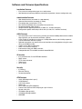
General Features
• Easy to Set Up: Installation is a simple and straightforward procedure. You will be up and
running in just a few minutes.
• Web-base Configuration: The Diva 2440 is configured via a web browser. Settings are
organized in logical groups, and making changes is quick and easy.
• Command Line Interface: All settings can also be configured using a command line interface
(Telnet application required).
ADSL and Network Features
• Support for Full-rate and G.Lite ADSL: The Diva 2440 is an ADSL (Asymmetric Digital
Subscriber Line) device supporting transfer of up to 8 Mbps. Two popular versions of ADSL
are built in to the Diva 2440, Full-rate and G.Lite.
• DHCP Support: The Diva 2440 can act as a DHCP server for your LAN. This lets you avoid
having to assign specific IP addresses to the computers on your network.
Hardware Features
• USB and Ethernet Ports: The Diva 2440 can connect to your computer through both the
Ethernet and USB ports (USB is Windows 98/2000/Me only). Setup via either port is simple
and easy. You can also connect the Diva 2440 to an Ethernet hub, giving all computers on
the network access to the Internet.
• Simultaneous Port Usage: The USB and Ethernet ports can be used simultaneously. You
can connect one computer to the Ethernet port and another to the USB port, and both devices
can access the ADSL line when needed or exchange data between the two local computers.
See Connection Scenarios on page 8 for more information.
• Upgradable Firmware: The Diva 2440’s firmware (a set of software instructions that tells the
device how to operate) is stored in flash memory on the device. This makes it easy to upgrade
the firmware should it become necessary to do so.
Introduction
Page 6
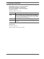
Package Contents
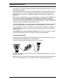
Your package should contain the following.
Diva 2440
Quick Install Guide
Ethernet Crossover
Cable (Yellow)
Ethernet Straight-through
Cable (Blue or Grey)
ADSL
Phone Cable
USB Cable
Power Supply
CD-ROM
The yellow Ethernet cable is a crossover cable and is used to connect the Diva 2440 directly to
a single computer. To connect the Diva 2440 to a network hub, you must use the included
straight-through Ethernet cable. (This cable may be blue or grey.) You can also connect the
yellow cable to the hub’s uplink port, if available.
In addition, your package may include the following:
• A phone adapter may be provided for the ADSL cable if your wall jack is not RJ11 compatible.
• A microfilter may be provided if an ADSL splitter is not being used on your premises. The
microfilter is connected between regular telephone devices and wall jacks in order to reduce
background noise. If you are unsure if you should use a microfilter, contact your ADSL provider.
Introduction
Page 7
Connection Scenarios
The Diva 2440 has both a USB port and an Ethernet port. Both ports can be used at the same
time, providing some flexibility in how you set up your equipment. You can also connect the
Ethernet port to a third-party Ethernet hub.
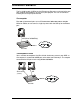
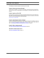
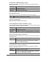
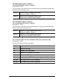
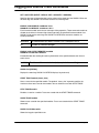
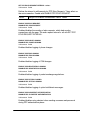
One Computer
For all operating systems that support an Ethernet network card, you may connect to the
Diva 2440 via the Ethernet port. If you are using Windows 98, Windows 2000, or Windows
Millennium Edition, you can connect a single computer to either the USB port or the Ethernet
port.
Ethernet cable (crossover) or
USB (Windows 98/2000/Me only)
ADSL line
Diva 2440
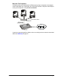
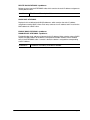
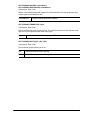
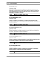
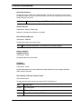
Two Computers at Once
You can connect two computers to the Diva 2440 for simultaneous access to your ADSL line.
One computer is connected to the USB port and the other to the Ethernet port. The computer
connected to the USB port must be using Windows 98/2000/Me.
Ethernet cable
(crossover)
USB
ADSL line
Diva 2440
Introduction
Page 8
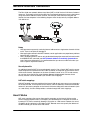
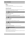
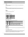
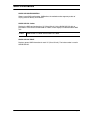
More than Two Computers
A third-party hub can be connected to the Ethernet port, giving all computers on the network
access to the ADSL line. Furthermore, you are still free to connect a computer to the USB port
as long as the computer is using Windows 98/2000/Me.
Ethernet cables
Third-party hub
Ethernet cable
(straight-through)
ADSL line
Diva 2440
If you plan on connecting the Diva 2440 to a hub or an existing local-area network as described
above, see LAN Setup on page 24.
Introduction
Page 9
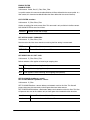
How ADSL Works
ADSL uses regular household telephone lines to receive and transmit data. To accomplish this
task, ADSL data is transmitted on frequencies outside of the normal voice call range. This way
the signals from the two devices do not interfere with each other.
ADSL provides two major benefits:
• Phone lines always free: Although the Diva 2440 uses the same wiring as your regular
telephone, you can still pick up the phone and make a call at any time.
• Instant access: Unlike traditional dial-up modems, a connection made using the Diva 2440
is always on. You no longer have to wait while your modem dials into your Internet provider.
Splitters and ‘Splitterless’ Operation
A splitter is a device installed at the entry point of the telephone line to your house and is used
to eliminate interference between the ADSL and voice signals. However, splitters must be
installed by a technician from your telephone company and usually require new telephone
wiring to be installed.
The Diva 2440 can operate with or without a splitter with both Full-rate and G.Lite ADSL.
Microfilters
For most splitterless installations, you most likely will need to install a microfilter between your
telephone devices (telephone, fax machine, answering machine) and the telephone jacks.
Microfilters filter out the frequencies outside of the normal voice call range and reduce
interference between ADSL transmissions and voice transmissions.
See About Microfilters on page 33 for more information. Microfilters may or may not be
included in your package. Contact your ADSL provider for more details.
Introduction
Page 10
Setup
This section describes how to set up your Diva 2440 to a single computer. General instructions
for a LAN installation are also included.
Overview .......................................................................................................12
Internet Account Information......................................................................13
Ports and Indicator Lights...........................................................................14
Step 1: Connect the Cables ........................................................................16
Step 2: Access the Diva 2440 Web Interface .............................................18
Step 3: Complete the Internet Wizard ........................................................19
Optional: Installing the Diva Assistant ......................................................21
Connecting a Second Computer ................................................................23
LAN Setup.....................................................................................................24
TCP/IP Setup ................................................................................................27
Troubleshooting ...........................................................................................31
Connecting a Phone to the Pass-through Phone Port .............................32
About Microfilters ........................................................................................33
Technical Support........................................................................................34
Setup
Page 11
Overview
Before you begin, please read the following general installation information.
Connecting to Both Ports
Once you connect a computer to either the USB or Ethernet port, you can connect a second
computer to the unused port without reconfiguring the Diva 2440. However, to help ensure a
problem-free setup, connect only one computer and verify that the device is working correctly
before connecting a second computer.
Requirements
Your system requirements will depend on the type of installation and the computer you are
using.
Ethernet
The Diva 2440 will work with any computer equipped with the
following:
• A 10BASE-T Ethernet network interface card, properly installed and
configured to use the TCP/IP protocol. Consult the documentation
that came with your card for instructions on how to do this. A
100 Mbps Ethernet card can be used if the card supports
auto-sensing.
• TCP/IP communications protocol configured to obtain its IP address
automatically (DHCP client), and not configured to use a DNS server.
See TCP/IP Setup on page 27 for more information.
USB
To connect using the Diva 2440’s USB port, you will require a
computer running Windows 98, Windows 98 SE, Windows 2000, or
Windows Millennium Edition, equipped with an freeUSB port. You
cannot use the Diva 2440’s USB port with Windows 95, Windows NT,
Apple® Macintosh®, or other systems.
Web Browser
The Diva 2440 is configured via web pages stored on the device. To
use the web interface, you must be using Netscape Navigator 3.01 or
Microsoft® Internet Explorer 4, or later versions. Additionally, your
Web browser must be configured to connect to the Internet via a local
area network (LAN) and not through a proxy server.
An installer for Microsoft Internet Explorer is included on the Diva
CD-ROM for all Windows operating systems except Windows 3.1.
Windows NT® 4.0 requires SP3 or later, available from
www.microsoft.com.
Diva Assistant
Setup
The Diva 2440 includes the Diva Assistant software, compatible with
all Windows operating systems except Windows 3.1. The Diva
Assistant provides convenient utilities and is also very useful during a
LAN setup, but it is not required in order to use the Diva 2440.
Page 12
Internet Account Information
During setup, you must enter account information as specified by your provider. Write this
information down for future reference.
• VPI setting
• VCI setting
• Encapsulation
• Connection Type
• Username and password, if your connection type is set to ‘PPP over Ethernet’ or ‘PPP over
ATM’.
• IP and DNS addresses, if your connection type is set to ‘IP over ATM’.
Note: Most or all settings should be supplied by your ADSL provider.
Setup
Page 13
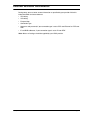
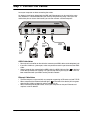
Ports and Indicator Lights
Before you begin installation, take a moment to become more familiar with the ports and
indicator lights of the Diva 2440.
Ports
ADSL Port
This port is used for connecting
the ADSL cable to your
telephone jack.
Phone Port
This port is used for connecting a telephone
or other analog device, and is available with
certain models only.
USB Port
Used for connecting the Diva 2440 to a computer
equipped with a USB port. Can only be used with
computers running Windows 98, Windows 2000, or
Windows Millennium Edition. It cannot be used with
Windows 95, Windows NT, Macintosh, or other systems.
Setup
Reset Button
The reset button is located on the
side or on the bottom, depending
on the model. Press this button
once to reset the device. Warning:
Pressing the Reset button for 15
seconds resets the device back to
factory defaults.
Power Connector
Used for connecting the
Diva 2440 to an electrical outlet.
Ethernet Port
Used for connecting the Diva 2440 to a
computer’s Ethernet adapter or to a
network hub.
Both the Ethernet and USB ports can be used at the
same time, providing Internet access for two
computers without a hub. You can also connect the
Ethernet port to a hub and use the USB port with
another computer.
Page 14
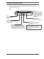
Indicator Lights
Power Light
Solid Green: The unit is on and working correctly.
Off: The power adapter is not connected.
Red: The device has encountered a fault condition or is
in boot mode. Press the Reset button once to return the
device to normal.
Ethernet Light
Solid Green: The Ethernet cable
is connected properly.
Flashing: Data is being transferred
to or from your computer over the
Ethernet cable.
Off: The Ethernet cable is
not connected.
Setup
USB Light
Green: The USB cable is properly
connected and the operating system is
configured to use the device.
Flashing: Data is being transferred to or
from your computer over the USB cable.
Off: The cable is not connected properly
or the operating system is not configured
for this device. This light may also go off if
your computer is put in low power mode.
ADSL Light
Solid Green: An ADSL connection has
been established.
Flashing Green: The Diva 2440 is
attempting to synchronize with your
provider’s ADSL network.
Off: The ADSL cable is not connected
properly, or your ADSL service provider
has not yet activated ADSL services on
your line.
Receive and Transmit Lights
Flashing: Data is being received or
transmitted via the ADSL connection.
Off: Data is not being received or transmitted.
Page 15
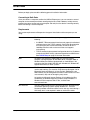
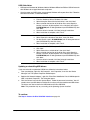
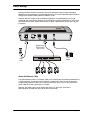
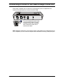
Step 1: Connect the Cables
Leave your computer on when connecting the cables.
As shown in the diagram below, both the USB and Ethernet ports can be used at the same
time. However, it is recommended that you use only one port during setup. Once you have
verified that you can access the Internet, you can then connect a second computer.
ADSL
Cable
USB
Cable
Yellow
Ethernet
Cable
Power
Adapter
To
Phone
Jack
ADSL Cable Notes
• Do not install a microfilter on the cable that connects your ADSL device to the telephone jack.
• If your Diva 2440 has a phone port, make sure you do not use this port to connect the ADSL
cable.
• Several seconds after connecting the ADSL cable, the ADSL indicator light (
on the front
of the device) should start flashing. This light will stop flashing and stay on when a link has
been established with your ADSL service provider’s network.
Ethernet Cable Notes
• The Ethernet port can be used with any computer supporting an Ethernet card and TCP/IP.
• When connected, the Ethernet indicator light (
on the front of the device) will turn green
when the Diva 2440 is plugged in and the computer is on.
• When finished connecting the cables, restart your computer so that your Ethernet card
acquires a new IP address.
Setup
Page 16
USB Cable Notes
• USB requires Windows 98, Windows 2000, or Windows Millennium Edition. USB will not work
with Windows 95 or Apple Macintosh computers.
• Once the power and USB cables are connected, Windows will request driver files. Follow the
onscreen instructions, as described below.
Windows 98
1.
2.
3.
4.
5.
6.
Windows Me
1.
2.
3.
4.
Windows 2000
1.
2.
3.
4.
5.
6.
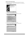
Insert the Diva CD-ROM into your CD-ROM drive.
From the ‘Hardware Wizard’ window, click ‘Next’.
Select the option ‘Search for the best driver’, then click ‘Next’.
When asked for the location of the driver files, select ‘Specify a
location’ and clear all other options. In the ‘Location’ field, type in
D:\USB\WIN98 (with ‘D’ being the letter of your CD-ROM drive), then
click ‘Next’.
Once the driver is located, click ‘Next’ to begin installation.
When installation is complete, click ‘Finish’.
Insert the Diva CD-ROM into your CD-ROM drive.
Select ‘Specify the location of the driver’, then click ‘Next’.
For the location, type in D:\USB\WIN98 (with ‘D’ being the letter of
your CD-ROM drive), then click ‘Next’.
When installation is complete, click ‘Finish’.
Insert the Diva CD-ROM into your CD-ROM drive.
Click ‘Next’.
Select ‘Search for a suitable driver’, then click ‘Next’.
When asked for the location of the driver files, select ‘Specify a
location’ and clear all other options. In the ‘Location’ field, type in
D:\USB\WIN98 (with ‘D’ being the letter of your CD-ROM drive), then
click ‘Next’.
Once the driver is located, click ‘Next’ to begin installation.
When installation is complete, click ‘Finish’.
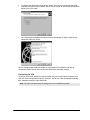
Updating or reinstalling USB drivers
If you must reinstall or update the USB drivers, follow the instructions below.
7.
From your desktop, right-click ‘My Computer’, click ‘Properties’, then click the ‘Device
Manager’ tab. The System Properties window opens.
8.
Double-click ‘Network Adapters’, right-click ‘Eicon Diva 2400 Series Virtual LAN Adapter for
USB’, and select ‘Properties’. The dialog box opens.
9.
Click the ‘Drivers’ tab and click ‘Update Driver’. Follow the onscreen instructions. You will
asked to insert your Windows Installation Disk, and you will also need the new USB drivers.
The drivers are also located in the USB folder on the Diva CD-ROM.
Note: This procedure may vary according to the Operating System installed.
To continue
See Step 2: Access the Diva 2440 Web Interface on page 18.
Setup
Page 17
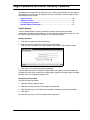
Step 2: Access the Diva 2440 Web Interface
To access the Internet through your provider’s network, you must first enter configuration
information, such as username and password, via a web browser (Internet Explorer 4.0 or
later, or Netscape Navigator 3.0 or later). If you do not have a web browser, an installer for
Internet Explorer for Windows is located in the ‘bonus’ folder on the Diva CD-ROM.
1.
Make sure you have restarted your computer. (If you are using the USB port, Windows should
have already asked you to do so upon installation of the USB drivers.)
2.
Launch your web browser.
3.
Click ‘File’, ‘Open’, enter 192.168.1.1 and click ‘OK’.
4.
The Diva 2440 main configuration page should appear.
Note: If you do not see the main configuration page, see Troubleshooting on page 31.
5.
Setup
To continue, see Step 3: Complete the Internet Wizard on page 19.
Page 18
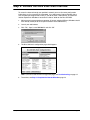
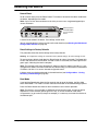
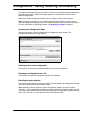
Step 3: Complete the Internet Wizard
All parameters should be specified by your ADSL provider. See Internet Account Information
on page 13 for more information.
1.
From the main menu, click ‘Internet Wizard’.
‘Internet
Wizard’
link
2.
This first page of the Internet Wizard displays the detected VPI/VCI settings for your
ADSL connection.
If the default settings are incorrect, click the ‘Internet Wizard - Step 1 (Advanced)’ link to edit
the settings. Otherwise, click the ‘Next’ button to continue.
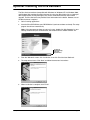
3.
In Step 2 of the wizard, you are presented with ‘encapsulation’ and ‘connection type’ settings.
Normally, these settings are detected automatically, and you should only have one option
for each.
Click the ‘Next’ button to continue.
Setup
Page 19
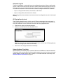
4.
Step 3 in the wizard will differ depending on the connection type specified in Step 2.
• If you are using a connection-oriented type (‘PPP over Ethernet’ or ‘PPP over
ATM’), you will be asked to enter your username and password.
• If you are using an always-on connection type (‘IP over ATM’), you will be asked
for your IP and DNS addresses.
Click the ‘Finish’ button to complete the setup wizard.
If an error is reported, see Troubleshooting on page 31.
Setup Complete!
Congratulations! You may now surf the Internet!
Try accessing an external web page, such as www.eicon.com (Eicon Networks’s web site).
It is recommend you register your purchase right away. Visit the Diva 2440 web page at
www.eicon.com/diva2440.
Setup
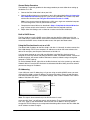
Page 20
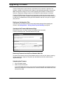
Optional: Installing the Diva Assistant
The Diva Assistant software (compatible with Windows 9x, Windows NT 4.0, Windows 2000,
and Windows Me) provides convenient features for using your Diva 2440, such as viewing of
device performance and log messages, easy access to the web interface, and firmware
upgrade. The Diva Assistant also provides status information for the device. However, use of
the Diva Assistant is optional.
1.
Quit all running applications.
2.
Insert the Diva CD-ROM into your CD-ROM drive if you have not done so already. The setup
program should start automatically.
Note: If the setup program does not start on its own, double-click ‘My Computer’ on your
desktop, double-click your CD-ROM drive, then double-click the ‘CDSETUP.EXE’ file.
To change the
displayed language,
click on this
drop-down menu.
Setup
3.
From the ‘Welcome’ screen, click ‘Installation’, then click ‘Diva Assistant Software’.
4.
The setup wizard starts. Click ‘Next’ and follow the onscreen instructions.
5.
When installation is complete, click ‘Finish’.
Page 21
6.
After you click ‘Finish’, you will see a message stating that you must restart your computer.
Click ‘Yes’.
You may encounter problems using the software if you do not restart your computer after
installation.
Once you have returned to the Windows desktop, the Diva Assistant icon will be visible in
the system tray. Double-click the icon to open the software.
A Diva Assistant shortcut is also copied to your desktop.
Setup
Page 22
Connecting a Second Computer
Once you connect a computer to either the USB or Ethernet port, you can connect a second
computer to the unused port without reconfiguring the device. However, to help ensure a
problem-free setup, connect only one computer and verify that the device is working correctly
before connecting a second computer.
If you are connecting a second computer to the Ethernet port, make sure that the computer is
set to acquire its IP address from a DHCP server, as described in TCP/IP Setup on page 27.
Once you connect the cable, restart your computer. You should then be able to access the
Internet.
Remember that the computer connected to the USB port must be using Windows 98,
Windows 2000, or Windows Millennium Edition. Once you connect the USB cable, follow the
instructions as described in USB Cable Notes on page 17. The USB drivers are located in the
‘USB’ folder on the Diva CD-ROM.
Setup
Page 23
LAN Setup
Installing the Diva 2440 on an existing LAN can be extremely simple or quite challenging,
depending on the complexity of your existing LAN setup. This section provides important points
to keep in mind when installing the Diva 2440 on a LAN.
However, due to the wide range of networking equipment and topologies that are in use
worldwide, your configuration needs may fall outside the strategy presented here. In this case,
you should contact your network administrator, or other support person to help you with your
installation.
Straight-through
Ethernet Cable
(Blue or Grey)
ADSL
Cable
Hub
Power
Adapter
About the Ethernet Cable
The yellow Ethernet cable is a crossover cable and is used to connect the Diva 2440 directly to
a single computer. To connect the Diva 2440 to a network hub, you must use the included
straight-through Ethernet cable. (This cable may be blue or grey.) You can also connect the
yellow cable to the hub’s uplink port, if available.
However, the yellow cable can be used if your hub has a uplink port. Consult the
documentation included with your hub for further information.
Setup
Page 24
General Setup Procedure
The following is a general guideline for the setup procedure you must follow when setting up
the device on a LAN.
1.
Connect the Diva 2440 to the hub on your LAN.
2.
Contact the Diva 2440 using a computer on your LAN as described in Step 2: Access the
Diva 2440 Web Interface on page 18. If you are using Windows, this is more easily done
with the Diva Assistant (see Using the Diva Assistant to set on a LAN).
Note: If you cannot contact the device over a LAN, use a single non-networked computer
for initial configuration, with the yellow Ethernet cable.
3.
Complete the Internet Wizard as described in Step 3: Complete the Internet Wizard on
page 19, then verify that the Internet is accessible from the required machines.
4.
Adjust other LAN settings, such as those on a router or on the Diva 2440 itself.
Built-in DHCP Server
The Diva 2440 has a built-in DHCP server. When you drop the Diva 2440 into a LAN, the
Diva 2440 senses if another DHCP server exists and de-activates its own DHCP services. To
re-activate the DHCP server, disable the other server, then press the Reset button.
Using the Diva Assistant to set on a LAN
The default LAN IP address for the Diva 2440 is 192.168.1.1. Normally, in order to contact the
Diva 2440 through TCP/IP, your computer’s IP address must be on the same subnet as the
device. For example, your computer could be set to 192.168.1.2.
If at least once computer on your LAN uses Windows, install the Diva Assistant on that
computer and use it to contact and configure the Diva 2440. The Network Wizard, a feature of
the Diva Assistant, will contact the Diva 2440 over a network, without having to change the
computer’s TCP/IP settings.
To use the Network Wizard, right-click on the Diva Assistant icon in the system tray and select
‘Network Wizard’. Once the Diva Assistant has discovered the Diva 2440, you will be asked if
you want to change its IP address.
IP Addressing
If your LAN uses static IP addressing, or if you are using an existing DHCP server, you must
assign the Diva 2440 a unique IP address. To change this setting, access the web interface,
click ‘Advanced Configuration’, click ‘System Settings’, enter a new IP address in the ‘LAN IP
Address’ field, then click ‘Save’.
LAN IP
address
Note: This step is done automatically if the Diva Assistant is used.
Once you click ‘Save’, you will lose contact with the device. To re-access the web interface,
click ‘File’, ‘Open’ in your web browser, then enter the new IP address. You may need to
change the TCP/IP settings on your computer before being able to access the Diva 2440 after
the IP address has been changed.
Setup
Page 25
However, if your computer is set to acquire its IP address dynamically from a DHCP server, you
need only restart your computer (or reset the IP address manually using ‘winipcfg’ with
Windows 9x or ‘ipconfig /renew’ for Windows 2000/NT). The Diva 2440 will assign the new
address.
Adjusting LAN Settings
The following are further changes you may need to make to your LAN setup. However, due to
the wide range of networking equipment and topologies, these are only guidelines.
If your LAN has a DHCP Server
If your LAN has a DHCP server, configure your DHCP server to return the address of the
Diva 2440 as the ‘Default Gateway’ and ‘DNS Server’ to all clients.
If your LAN uses Static IP Addresses
If your LAN uses static addressing, you must configure the TCP/IP settings on each computer.
Specifically, set each computer’s ‘Default Gateway’ and ‘DNS Server’ settings to the address of
the Diva 2440.
If your LAN has a router
If you have a router on your LAN, it is likely configured as the default gateway for your
computers. In this case, you will need to configure the routing table on your router to re-direct
the appropriate traffic to the Diva 2440.
Setup
Page 26
TCP/IP Setup
To be able to communicate with the Diva 2440 via Ethernet, your computer must have TCP/IP
installed and configured to act as a DHCP client. This allows your computer to acquire its IP
address and other settings from your provider’s DHCP server dynamically.
The following procedures describe how to set your TCP/IP settings for Windows 95,
Windows 98, Windows NT 4.0, Windows 2000, and Macintosh (Mac OS 8). For other
platforms, consult the documentation for your operating system.
• Windows 95/98 .................................................................................................... 27
• Windows NT 4.0................................................................................................... 28
• Windows 2000 ..................................................................................................... 29
• Apple Macintosh (Mac OS 8 or later)................................................................. 29
Windows 95/98
The following procedure describes how to verify and install TCP/IP on Windows 95 or
Windows 98. If TCP/IP is already installed on your system, go to Configuring TCP/IP (below).
Note that if you have more than one adapter installed on your system, you will have to use the
adapter that is in use by the Diva 2440.
1.
Click ‘Start’, ‘Settings’, ‘Control Panel’.
2.
Double-click the ‘Network’ icon. The ‘Network’ dialog box appears. By default, the
‘Configuration’ tab is displayed.
• If ‘TCP/IP’ is not listed for your network adapter in the ‘Components’ list, go to
Installing TCP/IP (below).
• If ‘TCP/IP’ is listed for your network adapter in the ‘Components’ list, then the
protocol is already installed. Go to Configuring TCP/IP (below).
Installing TCP/IP
1.
Click ‘Add’. The ‘Select Network Component Type’ dialog box appears.
2.
Select ‘Protocol’, then click ‘Add’. The ‘Select Network Protocol’ window appears.
3.
In the ‘Manufacturer’ box, select ‘Microsoft’.
In ‘Network Protocols’, select ‘TCP/IP’.
4.
Click ‘OK’. Once installation is complete, you are returned to the Network window.
5.
Do not click the ‘OK’ button yet; next you will verify your TCP/IP settings. Go to Configuring
TCP/IP (below).
Configuring TCP/IP
Setup
1.
In the list of components, select ‘TCP/IP’ for your network card, then click ‘Properties’. The
‘TCP/IP Properties’ dialog box appears.
2.
Click the ‘IP Address’ tab and select ‘Obtain an IP address automatically’. This defines your
machine as a DHCP client.
3.
Click the ‘WINS Configuration’ tab and select ‘Use DHCP for WINS Resolution’.
4.
Click the ‘Gateway’ tab and remove all existing gateways.
Page 27
5.
Click the ‘DNS Configuration’ tab and select ‘Disable DNS.’ This instructs your computer to
obtain DNS server information via DHCP.
6.
Click ‘OK’, then click ‘OK’ again.
Note: You may be asked to insert your original Windows installation CD-ROM.
7.
If prompted to restart your system:
• Click ‘No’ if you are next going to install the Diva Assistant. You are required to
restart after installing this software, and clicking ‘No’ will save you some time.
• Click ‘Yes’ if you do not need to install the Diva Assistant. Your computer must be
restarted in order to acquire a new IP address.
Windows NT 4.0
The following procedure describes how to install TCP/IP on Windows NT 4.0. If TCP/IP is
already installed on your system, see Configuring TCP/IP (below). Note that if you have more
than one adapter installed on your system, you will have to use the adapter that is in use by the
Diva 2440.
1.
Click ‘Start’, ‘Settings’, ‘Control Panel’.
2.
Double-click the ‘Network’ icon. The Network dialog box appears.
3.
Click the ‘Protocols’ tab.
• If ‘TCP/IP’ is not listed, go to Installing TCP/IP (below).
• If ‘TCP/IP’ is listed, then the protocol is already installed. Go to Configuring
TCP/IP (below).
Installing TCP/IP
1.
From the ‘Protocols’ tab, click ‘Add’.
2.
Select ‘TCP/IP protocol’ as your network protocol, then click ‘OK’.
3.
Click ‘Yes’ to use DHCP.
4.
When prompted, insert the original Windows NT installation CD and enter d:\i386 (where d:
is the drive letter of your CD drive), and click ‘Continue’.
5.
Do not click the ‘OK’ button yet; next you will verify your TCP/IP settings. Go to Configuring
TCP/IP (below).
Configuring TCP/IP
Setup
1.
Click the ‘Protocols’ tab.
2.
Select ‘TCP/IP protocol’, then click ‘Properties’.
3.
Select ‘Obtain an IP address from a DHCP server’.
4.
Click the ‘DNS’ tab. Delete any DNS addresses are configured.
5.
Click ‘OK’.
Page 28
6.
If prompted to restart your system:
• Click ‘No’ if you are next going to install the Diva Assistant. You are required to
restart after installing this software, and clicking ‘No’ will save you some time.
• Click ‘Yes’ if you do not need to install the Diva Assistant. Your computer must be
restarted in order to acquire a new IP address.
Windows 2000
Windows 2000 automatically created a network adapter profile (named ‘Local Area
Connection’ by default) when the adapter was installed. However, the TCP/IP protocol is not
installed by default. You must check if this profile has the Internet Protocol (TCP/IP) installed
and properly configured. Note that if you have more than one adapter installed on your system,
you will have to use the adapter that is in use by the Diva 2440.
1.
Click ‘Start’, ‘Settings’, ‘Network and Dial-up Connections’, then ‘Local Area Connection’.
(Note the name of this connection may be different as it can be changed by the user.) The
status window for this adapter is displayed.
2.
Click ‘Properties’. The properties window for this adapter is displayed.
• If ‘Internet Protocol (TCP/IP)’ is not listed in the ‘Components’ list, go to Installing
TCP/IP (below).
• If ‘Internet Protocol (TCP/IP)’ is listed in the ‘Components’ list, then the protocol
is already installed. Go to Verifying TCP/IP Settings (below).
Installing TCP/IP
1.
Click the ‘Install’ button. The ‘Select Network Component Type’ window appears.
2.
Select ‘Protocol’ and click ‘Add’. A list of available protocols appears.
3.
Select ‘Internet Protocol (TCP/IP)’ then click ‘OK’. Once the installation is complete, you are
returned to the properties window.
4.
Do not click the ‘Close’ button yet; next you will verify your TCP/IP settings. Continue with
Verifying TCP/IP Settings (below).
Verifying TCP/IP Settings
1.
Select ‘Internet Protocol (TCP/IP)’, then click ‘Properties’.
2.
The settings should be ‘Obtain an IP address automatically’ and ‘Obtain DNS server
automatically’.
3.
Click ‘OK’, then ‘OK’ again, then click ‘Close’.
4.
If prompted to restart your system:
• Click ‘No’ if you are next going to install the Diva Assistant. You are required to
restart after installing this software, and clicking ‘No’ will save you some time.
• Click ‘Yes’ if you do not need to install the Diva Assistant. Your computer must be
restarted in order to acquire a new IP address.
Apple Macintosh (Mac OS 8 or later)
TCP/IP is installed by default with your Mac OS. If it is not in the Control Panels folder, reinstall
it from your System Installation CD.
Setup
Page 29
1.
From the Apple menu, select ‘Control Panels’.
2.
Select ‘TCP/IP’.
3.
Set ‘Connect via’ to ‘Ethernet’.
4.
Set ‘Configure’ to ‘Using DHCP Server’.
5.
Close the TCP/IP control panel.
6.
Click ‘Yes’ to save the changes.
It is not necessary to restart your computer after making these changes. Your computer will
request a new IP address automatically.
Setup
Page 30
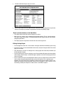
Troubleshooting
When troubleshooting, examine the state of the ADSL light (
Diva 2440.
) on the front panel of the
If the ADSL light is glowing continuously (is not blinking), a connection to the ADSL
network has been established. This means Internet access is possible. Try the following:
• Restart your computer and try accessing the Internet again.
• Verify that your setup information has been entered correctly as described in Step 2: Access
the Diva 2440 Web Interface on page 18.
• Verify that the TCP/IP settings for your Ethernet card are set to acquire an IP address
dynamically from a DHCP server. See TCP/IP Setup on page 27, or consult the
documentation that came with your operating system for information on verifying TCP/IP
settings.
• Verify that your Web browser is configured to use the local LAN, and is not configured to use
a proxy server. See Browser Settings on page 31 for instructions.
If the ADSL light blinks continuously or stays off, Internet access is not possible – the
Diva 2440 is unable to establish a connection with the ADSL network. Try the following:
• Check that your cables are connected properly.
• Verify that you have not connected a microfilter between the Diva 2440 and a telephone wall
outlet.
• Disconnect the power cable from the Diva 2440, wait a few seconds, then reconnect the cable.
If the ADSL light continues to blink or stays off, contact your ADSL service provider.
Browser Settings
If you are not able to access the configuration pages, verify your browser settings as described
below. Note that the steps may vary slightly depending on the browser version used.
• Internet Explorer version 5 or later:
- From the ‘Tools’ menu, select ‘Internet Options’, then click the ‘Connections’ tab. Click
‘Setup’.
- Select the option ‘I want to set up my Internet connection manually’, then click ‘Next’.
- Select ‘I want to connect through a local area network’, then click ‘Next’.
- Clear all proxy options, then click ‘Next’.
- Clear the option ‘Connect to the Internet immediately’, then click ‘Finish’.
• Internet Explorer previous to version 5:
- From the ‘View’ menu, select ‘Internet Options’, then click the ‘Connection’ tab.
- Verify that ‘Connect to the internet using a local area network’ is enabled.
- Verify that the ‘Proxy Server’ option is disabled.
• Netscape Navigator (do one of the following):
- Under Options, click ‘Network Preferences’, then ‘Proxies’. Verify that the ‘No Proxies’
option is selected.
- Under the ‘Edit’ menu, click ‘Preferences’, ‘Advanced’, then ‘Proxies’. Verify that the ‘Direct
Connection to the Internet’ is enabled.
Once finished making changes, click ‘OK’, then retry accessing the web-based configuration
pages.
Setup
Page 31
Connecting a Phone to the Pass-through Phone Port
Once setup is complete, you can connect an analog device (such as a telephone or fax
machine) to the phone port on the back of the Diva 2440.
The pass-through phone port on the
back of the Diva 2440 has a built-in
microfilter. Do not use a microfilter
when connecting a phone or fax
machine to this port.
Note: Telephone standards vary from region to region. If the cable for your analog device is not
RJ11 compatible, you must connect an adapter to the cable before connecting it to the phone port.
Setup
Page 32
About Microfilters
A microfilter is a small device designed to reduce interference between ADSL signals and your
regular telephone signals.
The use of microfilters is only required if your ADSL modem and your telephone devices share
the same wiring. This is known as ‘splitterless’ ADSL. Without microfilters, ADSL may cause
background noise on your phone. Additionally, ADSL data transfer may be interrupted by
phone calls.
Note: To test if the telephone jack you are using for ADSL is shared by another telephone jack
in your location, connect a plain telephone to the telephone jack intended for use by the
Diva 2440, and connect another telephone to the other telephone jack. Pick up the phone on
one jack and have someone else pick up the phone on the other jack, then talk. If you hear the
other person talking, the two jacks share the same wiring.
If microfilters are required, you must install one on each telephone device that shares the same
wiring as the ADSL signals, including telephones, answering machines, and fax machines.
If your installation uses a splitter, it should not be necessary to use microfilters as ADSL data is
carried on separate wiring up to the point of entry to your location. Contact your provider for
more information.
Your package may or may not include a microfilter. If you are unsure as to how to connect
the microfilter, or whether or not one is necessary, contact your ADSL provider.
Connecting a Microfilter
To install the microfilter, plug your phone or other analog device into the microfilter, then plug
the microfilter into your telephone jack, as shown below.
You must use one microfilter per telephone device in your location.
As telephone standards vary from region to region, your telephone equipment may vary than
those illustrated here.
Note: Do not install a microfilter on the cable that connects your ADSL device to the telephone
jack. It is also unnecessary to use a microfilter on the Diva 2440’s built-in phone port.
Setup
Page 33
Technical Support
• For technical support, visit our web site at www.eicon.com/support.
• For other contact information, visit www.eicon.com/support/contact.asp.
• For service, contact your Eicon Networks supplier.
Setup
Page 34
Using your Diva 2440
This section provides a general introduction to configuring and using your Diva 2440. More
specific information on the Diva 2440’s features are found later in this guide.
General Information .....................................................................................36
Resetting the Device....................................................................................37
Starting the Web-based Configuration Interface ......................................38
Configurations – Saving, Restoring, and Resetting .................................40
Upgrading Firmware ....................................................................................41
Login Password and other Security Features ...........................................43
About the Diva Assistant.............................................................................45
Using your Diva 2440
Page 35
General Information
The following are common questions related to your Diva 2440.
How do I dial out to my Internet Provider?
Internet access via ADSL is an ‘always on’ connection. You need only launch the application
you want to use (such as a web browser or e-mail program), and the Diva 2440 takes care of
the rest.
How do I register my Diva 2440?
Once you are up and running, you should visit the Eicon Networks web site and register your
Diva 2440. This ensures that you will always be kept up-to-date of new features and firmware
releases. Open the following URL in your web browser:
http://www.eicon.com/diva2440/
How do I make changes to device settings?
The Diva 2440 settings are accessed via a web browser. You log on to the device just like any
web server, go to the appropriate settings page, and make changes. To learn more about this
topic, see Starting the Web-based Configuration Interface on page 38.
How do I define a login password?
See Login Password and other Security Features on page 43.
What do the indicator lights mean?
See Ports and Indicator Lights on page 14.
Using your Diva 2440
Page 36
Resetting the Device
Normal Reset
To do a normal reset, press the ‘Reset’ button. This button is located on the side or underneath
the device, depending on the model.
Note: If your unit has the reset button on the side, you must use a straightened paperclip to
access this button.
Reset Button
Press this button
once to reset the
device.
A normal reset ‘reboots’ the device. Your settings are left intact.
You can reset the device via the main menu of the web interface (see Starting the Web-based
Configuration Interface on page 38).
Reset Settings to Factory Defaults
This procedure resets the device settings to the factory defaults.
Warning: As configuration settings are returned to factory default settings, all custom settings are lost.
To reset to factory defaults, hold down the ‘Reset’ button for about 15 seconds. The Power light
will turn red after the first five seconds, and after a total of 15 seconds, the Power light will turn
green again, indicating the reset is complete.
Note: This procedure will return the default IP address of the Diva 2440 to 192.168.1.1. If you
changed the IP address of the Diva 2440 from this default setting, you will need to use the default
IP address 192.168.1.1 to access the web configuration menu.
A factory reset can also be performed via the web interface (see Configurations – Saving,
Restoring, and Resetting on page 40).
Boot Mode
If you hold the Reset button down for five seconds, then let go of the button, the Diva 2440
enters ‘Boot Mode’. This mode is used for advanced installation and troubleshooting purposes.
Press the ‘Reset’ button once more to return the device back to normal operation.
Note: The device is not accessible via USB when in boot monitor mode, or when the device
experiences a fault condition (power light turns red). To access the device under these
circumstances (to get a memory dump, for example), it is necessary to connect the device via
the Ethernet port.
Using your Diva 2440
Page 37
Starting the Web-based Configuration Interface
Only one user can access the web-based configuration interface at a time.
Procedure
1.
If you installed the Diva Assistant software, right-click the Diva 2440 icon in the Windows
system tray, then click ‘Properties’. Once the Diva Assistant window opens, click ‘Tools’ then
‘Configure’.
If you did not install the Diva Assistant software, start your web browser software, click ‘File’,
‘Open’, enter 192.168.1.1 and click ‘OK’. (If you changed the address of the Diva 2440, enter
the new name or address instead.)
Note: You can also use the word diva or diva.dsl instead of the 192.168.1.1 IP address
(Internet Explorer 5.0 or later required).
2.
If a password has been defined for your Diva 2440, you will see the ‘Log In’ page. Enter the
system password and click ‘Log In’.
If your Diva 2440 has no password, this page will not be shown and you will go directly to
the main menu (see next step).
Note: By default, there is no password. If you have forgotten your password, you can hold
down the reset button for 15 seconds to reset the device to factory defaults. This will erase
the existing password. However, you will also lose all customize configuration settings,
including username and password you may have entered in order to access your Internet
service.
Using your Diva 2440
Page 38
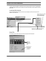
3.
The Diva 2440 then displays the main menu.
4.
Click on any of the links in the ‘Administration’ section to change settings for that particular
feature. For example, passwords are grouped in the ‘Security Settings’ page.
‘Reset’ and other buttons on the Main Menu
• The ‘Reset’ button resets the device. Settings are not lost.
• When you click ‘Logout’, you are logged out of the web interface. This is a security feature.
The ‘Login’ page is then shown. It is recommended that you log out when you are finished
configuring the device.
• The ‘Display System Log’ button will show the most recent log entries.
Editing Settings Pages
• Each configuration menu has a ‘Save’ button. Changes take effect immediately upon saving.
• If you click ‘Cancel’, you are returned to the main menu, and your changes made in the current
page are not saved.
• Click ‘Reset Form’ to return all settings in the current page to the values they had when you
initially opened the page.
• To access online help, click on a setting’s name. A help window will appear with a description
of that setting. General help is available through a question-mark icon at the top right of most
(but not all) pages.
• If this is the first time you have configured the device, you may need to wait up to one minute
(after making changes) before being able to access the Internet. This is because your
computer may have initially been assigned its network settings from the Diva 2440, as the
ADSL line was down and your provider’s server was not available. If, after a minute, it is still
not working, reboot your computer in order to force a new DHCP request.
Using your Diva 2440
Page 39
Configurations – Saving, Restoring, and Resetting
The web-based configuration interface makes it easy to save and restore configuration settings
on the Diva 2440. This is useful for backup purposes or if you intend to maintain several
different configurations.
When you save the configuration settings, they are stored in a file on your computer.
Note: Configuration settings are not lost when upgrading the firmware to a newer version.
However, configuration settings may not be saved if you load an older firmware on the device.
For more information on upgrading firmware, see Upgrading Firmware on page 41.
Accessing the Configuration Page
From the main menu, click the ‘Configuration’ link (bottom left of the screen). The
‘Configuration Maintenance’ page appears.
Backing up the current configuration
Click ‘Backup’ to save your configuration settings to a file on your computer.
Restoring a configuration from a file
Click ‘Browse’ to select the configuration file, then click ‘Restore’.
Resetting to factory defaults
Click ‘Reset factory settings’ to return all settings to factory defaults. All configuration changes
you have made will be returned to default values.
Note: Resetting to factory defaults will return the default IP address of the Diva 2440 to
192.168.1.1. If you changed the IP address of the Diva 2440 from this default setting, you will
lose contact with the web configuration interface after the reset is completed. To get back to main
menu, enter 192.168.1.1 in your browser’s URL field and press Enter.
Using your Diva 2440
Page 40
Upgrading Firmware
The Diva 2440 contains special software, called firmware, that controls its operation. The
firmware is stored in flash memory, which allows it to be replaced by uploading a new version.
Note: Configuration settings are not lost when upgrading the firmware to a newer version.
However, configuration settings may be lost if you upload an older firmware to the device.
The Diva CD-ROM contains firmware that may be newer or older than the version currently
installed on your Diva 2440. In addition, Eicon Networks posts the latest Diva 2440 firmware on
its web site. An added benefit of visiting the Eicon Networks web site is that you can register
your purchase.
Backing up Configuration Files
If you wish, you can create a backup of your configuration settings before updating your
firmware. See Configurations – Saving, Restoring, and Resetting on page 40.
Opening to the Firmware Maintenance Page
From the main menu, click the ‘Firmware’ link (bottom left of the screen).
The Diva 2440 displays the ‘Firmware Maintenance’ page.
Retrieving Firmware from the Eicon Networks Web Site
To retrieve new firmware from the Eicon Networks web site, click the ‘Visit’ button. A working
Internet connection is required. This points your web browser to the Diva 2440 firmware
upgrade web page.
Uploading New Firmware
1.
Click the ‘Browse’ button.
2.
Select the new firmware file.
If you downloaded new firmware, point to the file you downloaded from the Eicon Networks
web site. A firmware file is also located in the ‘Firmware’ folder on the CD-ROM that came
with your Diva 2440.
Using your Diva 2440
Page 41
3.
Click the ‘Upgrade’ button to upload the firmware to the Diva 2440.
This may take a few minutes. Do not turn off or unplug the device during this time.
When complete, the Diva 2440 is automatically reset to activate the new firmware. There is
no need to click the ‘Reset’ button on the main menu.
Using your Diva 2440
Page 42
Login Password and other Security Features
Connecting your computers to the Internet creates a wide range of benefits, but also exposes
your computer to certain risks. To safeguard your data and systems, the Diva 2440 provides
the following security features:
•
•
•
•
Login Password................................................................................................... 43
Automatic Log Out .............................................................................................. 44
IP Filtering Security Level .................................................................................. 44
Network Address Translation............................................................................. 44
Login Password
The Diva 2440 provides a system password that restricts access to the web-based
configuration and command line interfaces. This ensures that configuration changes can only
be made by authorized personnel. By default, no password is defined.
Defining a password
1.
From the main page, click ‘Security Settings’.
2.
Enter the current password in the ‘Old Login Password’ field.
Enter the new password in the ‘Login Password’ and ‘Repeat Login Password’ fields.
3.
Click ‘Save’. The changes take effect immediately.
If the password you enter in ‘Old Login Password’ does not match the current password, the
changes will not be saved. Likewise, if the ‘New Login Password’ and ‘Repeat Login Password’
fields do match, the changes will not be saved.
Erasing the system password
To erase the system password:
1.
Open the ‘Security Settings’ menu.
2.
Enter the current password in the ‘Old login password field’.
3.
Clear the text (if any) in the ‘New Login Password’ and ‘Repeat Login Password’ fields.
4.
Click ‘Save’.
The next time you log in you will not need to enter a password.
Using your Diva 2440
Page 43
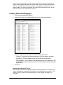
Automatic Log Out
The Diva 2440 applies an automatic time-out to configuration sessions. When a configuration
session is idle for more than the time-out value, the Diva 2440 automatically logs the user out.
This reduces the risk of unauthorized persons taking advantage of a logged-in computer that
has been left unattended. The time-out values cannot be configured and are set as follows:
• If you are using the web interface, the time-out is 30 minutes.
• If you are using Telnet, the time-out is 5 minutes.
Note: Changes that have not been saved are lost when the configuration session is terminated
this way.
IP Filtering Security Level
The IP Filtering Security level is a built-in set of IP Filtering parameters that controls what is
allowed through the Diva 2440 and onto your local network. The higher the security level, the
less traffic allowed in, but this increases the chances of barring legitimate traffic.
1.
From the main page, click ‘Security Settings’.
2.
Choose a security level from the drop-down menu.
Note: For information on what each filtering level means, click on the ‘IP Filtering Security
Level’ link to bring up the context sensitive help.
3.
Click ‘Save’. The changes take effect immediately.
Network Address Translation
Network Address Translation (NAT) is used to ‘hide’ the local LAN from all external resources.
The benefits of this are the ability for all connected computers to access the Internet using one
Internet address and ISP account. NAT is always on. For more information on this topic, see
Network Address Translation on page 52.
Using your Diva 2440
Page 44
About the Diva Assistant
The Diva Assistant provides a convenient way to manage your Diva Assistant. The following is
a brief description of how to use the software. For more information, consult the Diva Assistant
online help.
Launching the Diva Assistant
Once you install the Diva Assistant and restart your computer, the Diva Assistant icon will
appear in the system tray.
Right-click this icon to activate
this menu. Double-click to
launch the Diva Assistant.
The Diva Assistant
program group is installed
on your ‘Start’ menu.
Click here to launch
the online help.
Click ‘Close’ to close the Diva Assistant and
remove the icon from the system tray.
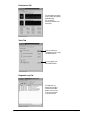
General Tab
The ‘General’ tab is the first tab you see when you open the Diva Assistant.
Reports the
status of the
front indicator
lights.
Click ‘Refresh’ to
fetch the latest
information on
your device.
Using your Diva 2440
Page 45
Performance Tab
This tab displays information
about incoming and outgoing
bandwidth usage.
You can drag the
performance windows onto
the desktop.
Tools Tab
Starts the web-based
configuration interface using
your default browser.
Lets you upgrade your
Diva 2440’s firmware.
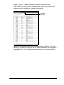
Diagnostic Log Tab
The Diagnostic Log
displays the messages
sent by the Diva 2440.
Double-click on an entry
to get more information
on a particular entry.
Using your Diva 2440
Page 46
Advanced Topics
This section provides detailed information on advanced topics concerning the Diva 2440, and
is aimed at the experienced computer and networking user.
Virtual Private Networking ..........................................................................48
Network Address Translation .....................................................................52
Command Line Interface (CLI)....................................................................56
Using TFTP to Transfer Files ......................................................................58
Advanced Topics
Page 47
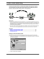
Virtual Private Networking
A virtual private network (VPN) is an interconnection between two networks that uses the
PPTP (point-to-point tunneling protocol). By using the Internet to transport data, a VPN can
eliminate long distance charges associated with traditional dial-up solutions. Since PPTP
provides a secure connection, network security is not compromised.
Diva 2440
Requirements
• If you are using Windows 95, Dial-Up Networking 1.3 (available from Microsoft’s web site at
http://www.microsoft.com) is required to create a VPN. Do not install DUN 1.3 on Windows 98
or Windows NT 4.0, as a VPN adapter is included with these operating systems; however, it
may not be installed (see below).
• From your network administrator, obtain the IP address or host name of the VPN server, as
well as the user name and password for each user who is to have access to the VPN.
Instructions
• Setting up a VPN with Windows 95/98 .............................................................. 48
• Setting up a VPN with Windows 2000 ............................................................... 50
• Connecting the VPN............................................................................................ 51
Setting up a VPN with Windows 95/98
Verify that your Internet access is working properly before setting up the VPN connection.
1.
Double-click ‘My Computer’, ‘Dial-Up Networking’, then ‘Make New Connection’. You will see
the following dialog box.
2.
Enter a name for your connection.
Advanced Topics
Page 48
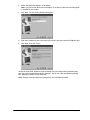
3.
Select ‘Microsoft VPN Adapter’ as the device.
Note: If you do not see ‘Microsoft VPN Adapter’ as an option, make sure the VPN adapter
is installed on your system.
4.
Click ‘Next’. You will see the following dialog box.
5.
Enter the IP address or host name of the VPN server in the ‘Host name or IP Address’ field.
6.
Click ‘Next’, then click ‘Finish’.
To connect to the VPN, double-click the connection you just created. When prompted, enter
your user name and password and click ‘Connect’. You will see a Dial-Up Networking dialog
box, showing the details of your connection.
Note: The bps value reported by this dialog box is your LAN Ethernet speed.
Advanced Topics
Page 49
Setting up a VPN with Windows 2000
Verify that your Internet access is working properly before setting up the VPN connection.
1.
Click ‘Start’, point to ‘Settings’, ‘Network and Dial-up Connections’, and then double-click
‘Make New Connection’.
2.
The ‘Network Connection Wizard’ opens. Click ‘Next’.
3.
Select ‘Connect to a private network through the Internet’ and click ‘Next’.
4.
Select ‘Do not dial the initial connection’, then click ‘Next’.
5.
Type the host name or IP address of the VPN Server, and then click Next.
Advanced Topics
Page 50
6.
The Connection Availability screen opens. Select ‘For all users’ to make the connection
available to all users on your network. Select ‘Only for myself’ to reserve the connection for
personal use. Click ‘Next’.
7.
The ‘Completing the Network Connection Wizard’ window opens. Type a name for the
connection, then click ‘Finish’.
You can create multiple VPN connections by copying them in the Network and Dial-up
Connections folder. You can then rename the connections and modify settings.
Connecting the VPN
To connect to the VPN, double-click the connection you just created. When prompted, enter
your user name and password and click ‘Connect’. You will see a Dial-Up Networking dialog
box, showing the details of your connection.
Note: The bps value reported by this dialog box is your LAN Ethernet speed.
Advanced Topics
Page 51
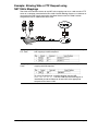
Network Address Translation
The Diva 2440 uses network address translation (NAT) to ‘hide’ the local LAN from all external
resources. The benefits of this are the ability for all connected computers to access the Internet
using one Internet address and ISP account. For example, when communicating with the
Internet, the two computers in the following diagram share the dynamically assigned address
‘222.182.22.39’.
Diva 2440
Notes
• NAT operates transparently, translating internal addresses to a single external one for all data
traffic. There is no effect on throughput.
• Most applications will work with NAT. However, certain applications may experience problems
because NAT is turned on.
• NAT is enabled by default, and can only be disabled through the command line interface with
the DISABLE NAT command (see NAT (Network Address Translation) Commands on
page 78 for more information). It is recommended that you do not turn NAT off unless you
have a specific requirement to do so.
Security benefits
An additional benefit of NAT is increased network security. Like a firewall, NAT restricts access
to the computers that reside on the local LAN. By default, no computer on the internal LAN is
visible to the Internet. Computers on the internal network cannot act as FTP or web servers,
nor can they share their drives using Windows Network Neighborhood. However, these
security features can be weakened if you use NAT static mappings.
NAT static mappings
With NAT enabled, computers outside of the internal LAN do not have access to any computers
on the internal LAN. The computers on the internal LAN are effectively invisible to the outside
network. If you need a computer on the internal LAN to be visible to the external network (such
as a web server), the Diva 2440 provides a solution through NAT static mappings.
How It Works
NAT static mappings allow you to allow specific computers on the internal LAN to receive
certain incoming network traffic. For example, you could designate a computer to receive all
incoming HTTP traffic, essentially allowing it to function as a web server. However, the actual
IP address of this computer is still hidden by NAT. Remote users must specify the address of
the Diva 2440 to gain access to the web server.
Advanced Topics
Page 52
When you create a NAT static mapping, the Diva 2440 routes all traffic for the protocol you
specify to the designated computer. This includes traffic normally handled by the Diva 2440
itself. Only one computer on the internal LAN can be designated to receive the traffic for a
specific protocol. This means, for example, you cannot create multiple web servers; all web
traffic must be sent to one computer on your LAN.
Creating Static NAT Mappings
1.
Launch the web configuration interface.
2.
From the main menu, click ‘Advanced Settings’, then click ‘NAT Static Mappings’.
3.
For each server that you want to define, specify the following parameters:
• ‘Protocol’: The protocol that remote computers will use to access the server.
• ‘Server port’: The port number that the protocol will use on the server.
• ‘Server address’: The IP address of the computer that will act as the server. The
server address must be on the same LAN as the Diva 2440 (or must be reachable
via the LAN).
4.
Click ‘Save’.
Specifying a Default NAT Server
When the Diva 2440 receives incoming datagrams containing protocols it is not supposed to
accept, the datagrams are discarded. For example, if an incoming datagram contains an FTP
request, and no FTP server has been defined using a static mapping, the datagram is
discarded.
Advanced Topics
Page 53
In some cases, you may want to forward all datagrams containing unspecified protocols to a
computer on your LAN. The Diva 2440 calls this computer the ‘default NAT server’.
To define a default NAT server, enter the IP address of the device that should receive these
datagrams into the ‘Default NAT server’ field on the IP Parameters panel. (From the main
menu, click ‘Advanced Configuration’, then ‘NAT Static Mappings’.
‘Default NAT
Server’ field
Note: The Diva 2440 handles traffic with the following protocols: HTTP, Telnet, TFTP, ECHO
(UDP port 7), and SNMP. Only traffic that does not contain these protocols will be forwarded to
the default NAT server. To forward the aformentioned protocols you must define a NAT static
mapping for each one.
Advanced Topics
Page 54
Example: Allowing Web or FTP Request using
NAT Static Mappings
Two of the most common reasons to use NAT static mappings are to run a web server or FTP
server on a computer connected to the Diva 2440. Use the following diagram as a reference as
you examine the NAT mapping examples that follow. Note that the Diva 2440 has been
assigned the static IP address 223.132.212.39.
Diva 2440
Configuring for
FTP Traffic
FTP traffic is carried on TCP ports 20 and 21. Therefore, the following two
NAT mappings would be required:
Configuring for Web Web traffic is carried on TCP port 80. Therefore, the following NAT
Traffic
mapping would be required:
To access the web server, a remote computer uses the URL
HTTP://223.132.212.39/. The Diva 2440 sees that the datagram is
intended for port 80 and forwards all web traffic to the appropriate
computer on the internal LAN.
Advanced Topics
Page 55
Command Line Interface (CLI)
The command line interface provides you with access to all Diva 2440 parameters. Some
advanced parameters are only accessible via this interface.
Prerequisites
To access the CLI, you will require:
• Telnet software for an IP connection (for Windows, Telnet or HyperTerminal).
• Connection via an Ethernet or USB port.
• System password to log on, if required (see Login Password on page 43).
Establishing a Telnet Connection
Make sure that you are using VT100 terminal emulation, otherwise the command line interface
may not display properly on your screen and certain keys will not function correctly.
1.
Start your Telnet software. (If you are running Window, you can click ‘Start’, ‘Run’, type
‘TELNET’, and press Enter.)
2.
Connect to the address 192.168.1.1.
Note: The address 192.168.1.1 is the default assigned to the Diva CD-ROM. If you have
changed the default address, use the new address.
3.
A welcome message appears on your screen. It will include a request to enter a password.
Note: The above example uses the telnet software included with Windows NT and 2000.
The screen was brought up by entering the command telnet 192.168.1.1 at a DOS prompt.
4.
Type the appropriate password and press Enter.
5.
The Diva 2440 displays the command line prompt ‘>’.
The Diva 2440 is now ready to accept your commands.
Advanced Topics
Page 56
Using the CLI
When using the CLI, the following keys are available:
• Up/down arrows: Moves back and forth through previously issued commands.
• F1: Provides help tailored to the current command you are entering. For example, if you are
part way through typing a command, it will show you the valid syntax to complete it.
Pressing F1 to bring up help does not work with Windows 2000. To retrieve the help
for a command, you must type the command, a space, then a question mark. For
example, typing in RESET ? will display help on the reset command.
• F2: List commands similar to what you are typing (does not work with Windows 2000).
• Tab or Space: To speed up entry of commands, you need only enter enough of the command
so that the CLI can uniquely recognize it, or press TAB or SPACE and the CLI will automatically
complete the current keyword for you. For example: The PROFILE command can be
shortened to PROF. Pressing TAB expands it to PROFILE.
When a command requires for a string of alphanumeric characters, you can use "" (two
double-quotes one after another) to enter an empty string.
About configuration context
The command line interface identifies the configuration context you are in by changing the
prompt. When you first activate the CLI interface you are in the General configuration context,
which is identified by a plain prompt (>). All other contexts are identified by a label added to the
prompt.
About profiles
To make the configuration of the Diva 2440 easier, the parameters that control its operation
have been combined into groups according to function. These groups are called profiles. When
you want to customize the operation of the Diva 2440, you use a CLI command to change the
setting of a parameter in one of its profiles. To do this, you must set the focus (also called the
configuration context) of the command line interface to be on that profile.
Connection profiles
Certain profiles define the characteristics of a connection, instead of just operational settings
for the Diva 2440. For example, the VC-1 profile defines a connection that enables the
Diva 2440 to connect using the Virtual Circuit defined the settings in the profile. When the
profile is active (to the ADSL line), the features and functions defined by the profile are active.
Default profiles
The Diva 2440 has following default profiles:
• VC-1: The default VC profile.
• LAN: The Diva 2440 LAN settings.
Command Line Reference
See Command Line Reference on page 60 for a complete list of all CLI commands and their
descriptions.
Advanced Topics
Page 57
Using TFTP to Transfer Files
The TFTP interface lets you upload and download configuration files and firmware. However, it
is often easier to use the web or command line interface to do most TFTP tasks.
Prerequisites
• The TFTP interface requires TFTP client software. A shareware client is included on the Diva
CD-ROM.
• Connection via an Ethernet or USB port (except when device is in boot or fault mode).
• Support for TFTP server must be enabled via command line interface.
Enabling TFTP server support
TFTP is disabled by default. To enable TFTP support, log into the CLI (see Command Line
Interface (CLI) on page 56) and enter the following commands.
enable tftp server
save
Uploading/downloading configuration files
All configuration settings on the Diva 2440 are stored in configuration files.
Using TFTP, you can access these files to retrieve and set configuration values.
File Name
Access
Mode
image.eim
Write
Boot / USB /
Contains the Diva 2440 firmware.
Normal Ethernet Write to this file to update the
firmware. After writing is complete, a
reset is automatically performed.
message.txt
Read-only
Boot
Ethernet Description of why boot monitor mode
was entered. You are in boot monitor
mode if the Power status indicator is
alternating between red and green.
You can enter boot monitor mode by
holding down the Reset button for
more than 5 seconds but less than 15
seconds. To exit boot monitor mode,
press the Reset button once.
dump.dmc
Read-only
Boot
Ethernet A file containing a memory dump. This
is used for troubleshooting purposes.
config.bat
Write-only
Normal USB /
A file containing CLI commands. The
Ethernet commands in this file are
automatically executed after being
uploaded with TFTP. Trace commands
are not supported by this file.
trace.bat
Write-only
result.txt
Read-only
Advanced Topics
Port
Description
Same as config.bat except that it
supports trace commands.
Normal USB /
Contains the results of the last .bat file
Ethernet that was executed.
Page 58
File Name
Access
Mode
Port
Description
config.all
Read-only
Contains the list of commands that
define the current active configuration.
Retrieve this file to view the entire
configuration of the Diva 2440.
config.bin
Read/write
Normal USB /
Contains a binary image of the current
Ethernet active configuration. You can
download this file to backup the
current configuration. (Download as a
binary file.)
system.log
Read-only
The system log contains a record of a
variety of events (trace data,
connected/disconnected messages,
security-related messages. warning
and errors messages) that have
occurred on the Diva 2440. The log
can contain over 15000 entries before
it wraps around.
Files marked as ‘boot mode’ can only be downloaded if the device is in boot mode (the power
light is flashing red; boot mode is entered if a hardware fault occurs or if you hold down the
reset button for five seconds and less than 15 seconds). Files marked as ‘normal mode’ can
only be accessed in normal operational mode.
Note: The device is not accessible via USB when in boot monitor mode, or when the device
experiences a fault condition (power light turns red). To access the device under these
circumstances (to get a memory dump, for example), it is necessary to connect the device via
the Ethernet port.
Examples
Loading New firmware via TFTP
To upload new firmware to the Diva 2440, use your TFTP client software to transfer the
firmware file. For example, using the TFTP program that comes with Windows NT, you could
issue the following command:
tftp -i 192.168.1.1 put 2440c1en.eim image.eim
...where:
• ‘192.168.1.1’ is the IP address of the Diva 2440.
• ‘2440c1en.eim’ is the name of the firmware you want to upload.
• ‘image.eim’ is the target file name on the Diva 2440. Do not change this name.
Retrieving message.txt
To retrieve the ‘message.txt’ file, which describes why boot monitor mode was entered, use the
following TFTP command.
TFTP -i 192.168.1.1 get message.txt filename.txt
Advanced Topics
Page 59
Command Line Reference
This section describes each command available from the Diva 2440.
Overview .......................................................................................................61
ADSL Commands ...........................................................................................62
ATM Commands .............................................................................................63
DHCP Commands ...........................................................................................64
Ethernet Commands .......................................................................................67
Filter Commands ............................................................................................68
General Commands ........................................................................................72
IP Commands (General) ..................................................................................74
IP Routing Commands ....................................................................................76
Logging and Internal Trace Commands...........................................................77
NAT (Network Address Translation) Commands ..............................................78
PPP Commands ..............................................................................................79
Profile Commands ..........................................................................................82
SAR Commands .............................................................................................83
TFTP Commands ............................................................................................84
Time Protocol Commands...............................................................................85
Command Line Reference
Page 60
Overview
This section provides a description for each CLI command. The commands are grouped
according to functionality.
Notational Conventions
The section uses the following conventions:
Syntax Example
Description
Cancel
Boldface type indicates the name of an item
(a parameter name, command button, menu option, etc.)
you need to select or perform an action on.
RESET
UPPERCASE TYPE indicates keywords. The actual words
can be entered in either uppercase or lowercase.
[ /C n ]
Items enclosed in square brackets are optional. You can
either include them or not. Do not enter the brackets. If the
items are separated by vertical bars, you must choose one
of the items. Enter only one item. Do not enter the vertical
bar.
numHops
Items in lowercase type are user-supplied input. Replace
these items with values appropriate to your system.
{ THIS | THAT }
Two or more items enclosed in braces and separated by a
vertical bars means you must choose one item. Enter only
one item. Do not enter the vertical bar.
Command Line Reference
Page 61
ADSL Commands
SHOW ADSL CONFIGURATION
Displays the current configuration for the ADSL line.
SET ADSL MODULATION TYPE [G_992_2 | MULTIMODE]
Sets the ADSL modulation type. If no argument is specified, the existing setting is
displayed. Default: Multimode.
G_992_2
Use G.lite ADSL (G.992.2).
MULTIMODE
Attempts to negotiate the following modulation types:
Full-rate (G.992.1), G.lite (G.992.2), and ANSI.T1.413.
SHOW ADSL STATISTICS
Displays the current statistics for ADSL line.
Command Line Reference
Page 62
ATM Commands
SHOW ATM CONFIGURATION
Valid context: Profile
Shows the ATM configuration settings for the ATM VC associated with the current profile.
Show ATM VC
Shows the table of ATM VCs (Virtual Circuits) and their properties.
SET ATM VC <vpi> <vci> <LLC | VCMUXBRIDGED> [rate | MAX]
Valid context: Profile
Configures an ATM VC (Virtual Circuit) for this interface.
<vpi>
Virtual Path Identifier. Range: 0-255.
<vci>
Virtual Channel Identfier. Range: 0-65535.
<encaps-type>
Encapsulation type (LLC or VCMUXBRIDGED).
LLC: Use LLC (may carry different protocols).
VCMUXBRIDGED: Use VC Multiplexed (carries only one type of
protocol).
[rate]
Optional 'max' or Peak Cell Rate in kilobits per second. Default:
MAX. Range: 1-832.
SET ATM SERVICE CATEGORY {UBR | CBR}
Valid context: Profile
Sets the ATM service category for the current profile.
UBR
Unspecified Bit Rate (default). No service guarantees. ATM cells are
sent but no feedback is returned about whether or not data has
reached its destination. Suitable for http, ftp, and other data transfer
protocols that are not time-sensitive.
CBR
Constant Bit Rate. This service category promises a constant
transport rate. Suitable for time-sensitive data transfer.
Command Line Reference
Page 63
DHCP Commands
SET DHCP TYPE <SERVER | RELAY | NONE>
Sets the type of DHCP services provided to other network devices. The DHCP server is
enabled by default.
SERVER
IP addresses will be dynamically assigned when a DHCP request is
received from a network device.
RELAY
Relays DHCP requests to a separate DHCP server (use SET DHCP
SERVERADDR to specify).
NONE
DHCP requests are ignored.
SHOW DHCP STATUS
Displays DHCP server status and a list of currently-defined IP addresses.
SET DHCP IPRANGE <startIPaddress> <range>
Defines the pool of addresses used to assign dynamic addresses when operating as a DHCP
server.
<startIPaddress>
Starting address for the pool. This address must be on the same
network as the LAN IP address. Default: 192.168.1.2.
<range>
Number of addresses in the pool. Range: 1-250. Default: 250.
Example: If the starting address is set to 192.168.1.2 and the range is set to 10, addresses
192.168.1.2 to 192.168.1.11 are available for DHCP.
SET DHCP LEASEDURATION <duration> <MINS | HOURS | DAYS>
Defines the length of time a client address assigned by the DHCP server is valid.
Range
30 minutes to 30 days.
SET DHCP DNS <PRIMARY | SECONDARY> <ipaddress>
Defines the primary and secondary DNS server addresses sent to a DHCP client when a
DHCP lease is requested. By default, the primary DNS is 192.168.1.1 (this is the default
address of the device); the secondary is blank.
<PRIMARY>
Primary DNS server.
<SECONDARY>
Secondary DNS server.
<ipaddress>
IP address of the DNS server.
Command Line Reference
Page 64
SET DHCP WINS <PRIMARY|SECONDARY> ipaddress
Defines the primary and secondary WINS server addresses sent to a DHCP client when a
DHCP lease is requested.
<PRIMARY>
Primary WINS server.
<SECONDARY>
Secondary WINS server.
<ipaddress>
IP address of the WINS server.
SET DHCP DOMAIN <domain>
Defines the domain name sent to a DHCP client when a DHCP lease is requested.
<domain>
Domain name, a string of up to 31 characters.
SHOW DHCP CONFIGURATION
Displays the settings for all DHCP-related parameters.
SET DHCP SERVERADDR <PRIMARY | SECONDARY> ipaddress
Defines where DHCP requests are forwarded when the device is acting as a DHCP relay agent
(using SET DHCP TYPE RELAY). DHCP is on by default.
<PRIMARY>
Primary DHCP server.
<SECONDARY>
Secondary DHCP server.
<ipaddress>
IP address of the DHCP server where requests are to be relayed.
ADD DHCP STATICMAP <ipaddress> <MACaddress>
Adds a new entry to the STATICMAP table, which contains the static IP address assignments
used by DHCP clients.
<ipaddress>
IP address in dotted-decimal notation (#.#.#.#).
<MACaddress>
MAC address of the target device. This address must be 12
hexadecimal digits separated by colons, commas, or hyphens
(11:22:33:44:55:66 for example).
SET DHCP STATICMAP <ipaddress> <MACaddress>
Modifies an existing entry in the STATICMAP table, which contains the static IP address
assignments used by DHCP clients.
<ipaddress>
IP address of the entry to modify.
<MACaddress>
New value for the MAC address of the target device. This address
must be 12 hexadecimal digits separated by colons, commas, or
hyphens (11:22:33:44:55:66 for example).
Command Line Reference
Page 65
DELETE DHCP STATICMAP <ipaddress>
Deletes an entry from the STATICMAP table, which contains the static IP address assignments
used by DHCP clients.
<ipaddress>
IP address of the entry to delete.
SHOW DHCP STATICMAP
Displays the list of defined static DHCP addresses, which contains the static IP address
assignments used by DHCP clients. Each entry consists of an IP address and IP mask for the
MAC address of a DHCP client.
ENABLE DHCP STATICMAP <ipaddress>
DISABLE DHCP STATICMAP <ipaddress>
Enables/disables static address assignment for this IP address. When a device makes a DHCP
request, the MAC address of the device is compared to the MAC address of each enabled
entry in the STATICMAP table. If a match is found, the device is assigned the corresponding
static IP address.
<ipaddress>
Command Line Reference
IP address of the entry to enable or disable.
Page 66
Ethernet Commands
SHOW ETHERNET STATISTICS
Displays Ethernet statistics.
SHOW ETHERNET ADDRESS
Valid context: Port
Displays the Ethernet address of the device. You must be in the LAN profile to issue this
command (type LAN and press Enter first).
Command Line Reference
Page 67
Filter Commands
NEXT
PREVIOUS
Valid context: IP_Filter, Ether_Filter
Sets the active context to the next or previous filter. This allows you to edit the filter.
ADD IP FILTER <number>
Valid context: Profile, Port
Adds a new IP filter at the specified position. A filter that already has the number you specify is
shifted one higher. Use SHOW FILTER to see a list of filters.
<number>
Position where new filter is to be added.
ADD ETHERNET FILTER <number>
Valid context: Profile, Port
Adds a new Ethernet filter at the specified position. A filter that already has the number you
specify is shifted one higher. Use SHOW FILTER to see a list of filters.
<number>
Position where new filter is to be added.
DELETE FILTER <number>
Valid context: Profile, Port
Deletes the specified filter. Use SHOW FILTER to see a list of filters.
<number>
Number of the filter that is to be deleted.
SET FILTER <number>
Valid context: Profile, Port
Sets the active context to the specified filter. This allows you to edit the filter.
Use SHOW FILTER to see a list of filters.
<number>
Number of the filter to edit.
SHOW FILTER
Valid context: Profile, Port, IP_Filter, Ether_Filter
Displays all filters for the current profile. If the active context is set to a specific filter, the list will
include entries defined for the current filter only.
Command Line Reference
Page 68
ENABLE FILTER
DISABLE FILTER
Valid context: Profile, Port, IP_Filter, Ether_Filter
In a profile context, this command enables/disables all filters defined for the current profile. In a
filter context, this command enables/disables the filters defined for the current filter only.
COPY FILTER <number>
Valid context: IP_Filter, Ether_Filter
Copies an existing filter to the current filter. This command is only available in the filter context.
Use SHOW FILTER to see a list of filters.
<number>
Number of the filter to copy.
SET ACTION <DROP | FORWARD>
Valid context: IP_Filter, Ether_Filter
Sets the action this filter takes when data matching the filter setting is encountered.
DROP
Discard the data.
FORWARD
Forward the data to the next filter.
SET DIRECTION <IN | OUT | ANY>
Valid context: IP_Filter, Ether_Filter
Defines whether a filter applies to incoming or outgoing data.
IN
Filter applies to incoming data only.
OUT
Filter applies to outgoing data only.
ANY
Filter applies to both incoming and outgoing data (default).
SET IP SOURCE <ipaddress> <mask>
SET IP DESTINATION <ipaddress> <mask>
Valid context: IP_Filter
SET IP SOURCE defines a source address and network mask for this filter. This filter will
process data from this source only and will ignore data from other sources.
SET IP DESTINATION defines a destination address and network mask for this filter. This filter
will process data sent to this address only and will ignore data intended for other locations.
<ipaddress>
Source IP address of data to filter.
<mask>
Source network mask of data to filter.
Command Line Reference
Page 69
SET UDP SOURCE <lowPort> <highPort>
SET UDP DESTINATION <lowPort> <highPort>
Valid context: IP_Filter
Sets the minimum and maximum source or destination UDP (User Datagram Protocol) ports
for which this filter will process data.
<lowPort>
Minimum UDP port number of data to filter.
Range: 0 to highPort. Default: 0.
<highPort>
Maximum UDP port number of data to filter.
Range: lowPort to 65535. Default: 65535.
SET TCP SOURCE <lowPort> <highPort>
SET TCP DESTINATION <lowPort> <highPort>
Valid context: IP_Filter
Sets the minimum and maximum source or destination TCP (Transmission Control Protocol)
ports for which this filter will process data.
<lowPort>
Minimum TCP port number of data to filter.
Range: 0 to highPort. Default: 0.
<highPort>
Maximum TCP port number of data to filter.
Range: lowPort to 65535. Default: 65535.
SET TYPE { ALL | UDP | TCP | SYN | ANYICMP | ICMP} [icmp_type] [icmp_code]
Valid context: IP_Filter
Sets the type of data to which this filter applies.
ALL
Applies to all data.
UDP
Applies to UDP data.
TCP
Applied to TCP data (default).
SYN
Applies to TCP connection (SYN) data.
ANYICMP
Applies to all ICMP data.
ICMP
Applies to specific ICMP data only (set by type and code)
icmp_type
ICMP type to filter (if ICMP is specified).
icmp_code
ICMP code to filter (if ICMP is specified).
Command Line Reference
Page 70
SET ETHERNET SOURCE <macaddress>
SET ETHERNET DESTINATION <macaddress>
Valid context: Ether_Filter
Defines a source/destination MAC address for an Ethernet filter. This filter will process data
matching this source/destination only.
<macaddress>
source or destination MAC address.
SET ETHERNET FRAMETYPE <type>
Valid context: Ether_Filter
Defines the Ethernet frame type for this filter. This filter will process data that uses this frame
type only and will ignore data with other frame types.
<type>
Hexidecimal number indicating type of Ethernet frame.
SET ETHERNET MULTICAST <ON | OFF>
Valid context: Ether_Filter
Turns Ethernet multicast filtering on or off.
ON
Enable Ethernet multicast filtering.
OFF
Disable Ethernet multicast filtering.
Command Line Reference
Page 71
General Commands
HELP
Displays the commands available in the current context, with a short description of each
command's functionality.
SAVE
Saves the current configuration settings to the device's non-volatile memory. Save your
changes before powering off or resetting the hardware; otherwise, changes are lost.
EXIT
LOGOUT
Closes the current configuration session.
SET TIME hh:mm[:ss]
Sets the internal system clock.
hh
Hours
Range: 00 to 24.
mm
Minutes
Range: 00 to 59.
ss
Seconds
Range: 00 to 59
SET DATE [yy]yy-mm-dd
Sets the internal system date in the format yyyy-mm-dd.
mm
Month
Range: 01 to 12.
dd
Day
Range: 01 to 31.
yyyy
Year
Can be entered as two or four digits. A two-digit year
between 00 and 70 is assumed to be after 2000.
Examples: 00 is 2000, 55 is 2055, but 85 is 1985.
SHOW DATE
SHOW TIME
Displays the current system date and time. You can set the date with SET DATE and the time
with SET TIME.
SET PASSWORD <password>
Sets the password users must specify when logging on to any of the configuration interfaces
(web, Telnet, etc.). Maximum of 10 alphanumeric characters, spaces are not allowed,
passwords are case-sensitive (‘PASS’ and ‘pass’ are not the same).
Command Line Reference
Page 72
RESET
Resets the device. Configuration settings are not lost.
RESET FACTORY
Resets the device, returning all parameters to their factory default settings.
Warning: This command deletes your password and all settings!
SHOW SYSTEM STATUS
SHOW VERSION
Displays system information: memory, firmware version, etc.
ENABLE ECHO SERVER
DISABLE ECHO SERVER
Enables/disables the echo server, which answers echo protocol queries sent to the echo
server port. UDP and TCP queries are supported. Echo server is disabled by default.
ENABLE SYSMAN
DISABLE SYSMAN
Enables/disables the Sysman module, which sends runtime statistics to external applications
running on your computer (such as the Diva Assistant). Disabling Sysman will prevent such
applications from displaying runtime status information. Sysman is enabled by default.
ENABLE SCROLL BREAK
DISABLE SCROLL BREAK
When Scroll Break is enabled, you will be prompted to press a key when output exceeds the
number of lines available in the Telnet window, as could happen when viewing a long trace or
log. Enabled by default.
Command Line Reference
Page 73
IP Commands (General)
SET IP ADDRESS <ipaddress>
Valid context: Profile, Port
Sets the IP address this profile should use if a static address is assigned to the device by your
ISP or network administrator. In most cases, specify 0.0.0.0 to allow dynamic negotiation when
the connection is established.
Note: Dynamic negotiation is not supported by the LAN profile.
SET IP MASK <ipaddress>
Valid context: Profile, Port
Sets the subnet mask for this profile.
SHOW IP ADDRESS
Valid context: GENERAL PROFILE PORT
Displays the current IP address. The addresses you see may be the ones negotiated by IP and
not the ones you have defined. For example, if an IP address is set to 0, it is negotiated to a
new value when the device connects. Addresses for the current profile are displayed unless
you are in the GENERAL context, in which case all addresses are displayed.
SHOW IP CONFIGURATION
SHOW IP STATUS
Valid context: Profile, Port
Displays IP configuration settings for the current profile or context.
ENABLE IP DIALONDEMAND
DISABLE IP DIALONDEMAND
Enables/disables IP dial-on-demand. When this feature is enabled, the actual connection will
be established only when the Diva 2440 receives an external access request. When
dial-on-demand feature is disabled, the unit is set to always-on mode.
SET IP DEFAULT GATEWAY
Sets the IP address of a default remote gateway. The command will modify/add a default IP
route pointing to the gateway specified in the argument.
Note: Setting the default gateway address is only necessary for IPoE profile type and only when
a static configuration is used (DHCP client is disabled).
SET IP DNS1
SET IP DNS2
Defines the DNS address (DNS1 for primary; DNS2 for secondardy) to be used by the internal
DNS relay.
Command Line Reference
Page 74
SHOW STATISTICS
Displays statistics for the IP protocol. These statistics reflect the combined usage of all profiles
that use the IP protocol and not statistics for a particular profile.
PING <ipaddress> [number] [size]
PING tests if an IP address is reachable by sending a packet to the receiving address
and waiting for a reply.
<ipaddress>
IP address of device you want to PING.
[number]
Number of messages to send. Range: 1-no limit.
Default: 4.
[size]
Message size in bytes Range: 1-1472. Default: 64.
Command Line Reference
Page 75
IP Routing Commands
ADD IP ROUTE <ipaddress> <mask>[:metric] [gateway]
DELETE IP ROUTE <ipaddress> [mask[:metric]]
SET IP ROUTE <ipaddress> <mask>[:metric] [gateway]
Valid context: Profile, Port
Adds/deletes/modifies a static IP route.
<ipaddress>
IP address of datagrams that should be routed.
<mask>
Mask for IP address. You can specify the number of bits checked
when comparing the address of a datagram to that specified by the
<ipaddress> parameter (range: 0-32) or the full IP mask in dotted
format. Optional for DELETE command.
[:metric]
Metric (i.e. cost) for the destination (optional).
[gateway]
If a match is found, datagrams are forwarded to this IP address
(optional).
SHOW IP ROUTE
Valid context: Profile, Port
Displays all defined static and dynamic IP routes.
Command Line Reference
Page 76
Logging and Internal Trace Commands
SET LOG FILTER {EVENT | DEBUG | INFO | SECURITY | WARNING}
Specifies the type of information that is to be written to the event log. Use SHOW LOG to see
the event log. Use SHOW LOG STATUS to see the current log filter.
ENABLE LOG MODULE <taskName | ALL>
DISABLE LOG MODULE <taskName | ALL>
Each firmware module issues status messages during operation. These commands enable or
disable the inclusion in the event log of messages from the specified firmware module. Use
SHOW LOG to see the event log. Use SHOW LOG STATUS to see which modules are
currently excluded.
taskName
A module name (as seen in SHOW LOG). Examples: DHCP.
ALL
Enable all module messages.
ENABLE LOG OUTPUT REMOTE hostAddr
DISABLE LOG OUTPUT REMOTE
Enables/disables the sending of event log information to the specified device each time an
event occurs.
hostAddr
IP address of the remote device (only required when enabling).
SHOW LOG [STATUS]
Displays the event log. SHOW LOG STATUS displays log status only.
START TRACE module [frame_size]
Starts a trace for the specified module. The optional ‘frame_size’ argument specifies the
maximum size of one frame for that module. You can disable a trace with STOP TRACE.
STOP TRACE module
Disables a trace for a module. Traces are started with the START TRACE command.
SHOW TRACE module
Shows traces saved for the specified modules. Traces are started with the START TRACE
command.
SHOW LOG PLUS module
Shows the log plus specified traces.
Command Line Reference
Page 77
NAT (Network Address Translation) Commands
ENABLE NAT
DISABLE NAT
Valid context: Profile, Port
Enables/disables NAT (Network Address Translation). NAT allows your router to use only one
IP address when communicating with remote sites via the ADSL port, effectively 'hiding'
connected devices. Enabled by default.
SHOW IP NAT
Displays the IP NAT table, which contains the settings for all computers on the internal LAN
that are visible to the external network.
ADD IP NAT <UDP | TCP> <port> <ipaddress>
DELETE IP NAT <UDP | TCP> <port>
ADD IP NAT allows a computer on the internal LAN to be visible to the external network for a
particular protocol. For example, if you want an internal computer to function as a SMTP
(E-mail) server, set TCP to port 25 and enter the IP address of the computer.
Use DELETE IP NAT to remove the NAT assignment.
UDP | TCP
UDP or TCP protocol.
<port>
Port to use.
<ipaddress>
IP address of the computer on the internal LAN.
SET IP NAT <UDP | TCP> <port> <ipaddress>
Changes an existing entry in IP NAT table.
UDP | TCP
UDP or TCP protocol.
<port>
Port to use.
<ipaddress>
IP address of the computer on the internal LAN.
Command Line Reference
Page 78
PPP Commands
SET PPP MRU <value>
Valid context: Profile
Defines the initial Maximum Receive Unit (MRU) the local PPP entity will advertise to the
remote entity. If set to 0, the local PPP entity will not advertise any MRU to the remote entity,
and the default MRU will be assumed. Takes effect when the link is next restarted (use the
DISCONNECT and CONNECT commands).
<value>
Range: 0-2147483647. Default: 1500.
SET PPP RESTARTDELAY <value>
Valid context: Profile
Defines the number of milliseconds to wait before retransmitting another
configure request when no valid response has been received. Takes effect on
the next connection.
<value>
Range: 0-2147483647. Default: 3000.
SET PPP MAX CONFIGURE <value>
Valid context: Profile
Defines the number of configure requests to transmit before considering the
link faulty. Takes effect on the next connection.
<value>
Range: 0-2147483647. Default: 10.
SET PPP MAX TERMINATE <value>
Valid context: Profile
Defines the number of terminate requests to transmit before going down when
no response is received. Takes effect on the next connection.
<value>
Range: 0-2147483647. Default: 2.
SET PPP MAX FAILURE <value>
Valid context: Profile
Defines the number of identical ‘Configure NAK’ messages to send before
rejecting an option. Takes effect on the next connection.
<value>
Command Line Reference
Range: 0-2147483647. Default: 5.
Page 79
SET PPP ECHO REQUEST INTERVAL <value>
Valid context: Profile
Defines the interval in milliseconds for PPP Echo Requests. Takes effect on
the next connection. Enable with ENABLE PPP ECHO REQUEST.
<value>
Range: 0-2147483647 milliseconds. Default: 10000.
ENABLE PPP ECHO REQUEST
DISABLE PPP ECHO REQUEST
Valid context: Profile
Enables/disables the sending of echo requests, which help monitor
connections with the peer. The echo request interval is set with SET PPP
ECHO REQUEST INTERVAL.
ENABLE PPP PHASE LOGGING
DISABLE PPP PHASE LOGGING
Valid context: Profile
Enables/disables logging of phase changes.
ENABLE PPP FSM LOGGING
DISABLE PPP FSM LOGGING
Valid context: Profile
Enables/disables logging of FSM changes.
ENABLE PPP NEGOTIATION LOGGING
DISABLE PPP NEGOTIATION LOGGING
Valid context: Profile
Enables/disables logging of packet exchange negotiations.
ENABLE PPP OPTION LOGGING
DISABLE PPP OPTION LOGGING
Valid context: Profile
Enables/disables logging of option build/check messages.
ENABLE PPP CLEARTEXT AUTHENTICATION
DISABLE PPP CLEARTEXT AUTHENTICATION
Valid context: Profile
Enables/disables using cleartext when sending username and password
during PPP authentication phase.
Command Line Reference
Page 80
SET PPP LOCAL USERNAME
SET PPP LOCAL PASSWORD
Valid context: Profile
Defines the username/password sent when replying to valid authentication
requests. For example, when connecting to an ISP, this is the name used to
log on in combination with your password. Range: 0-64 alphanumeric
characters (no spaces).
SHOW PPP CONFIGURATION
Valid context: Profile
Shows PPP layer configuration for the current profile.
Command Line Reference
Page 81
Profile Commands
PROFILE profileName
Changes the active context to the specified profile. If no name is specified, you are placed in
the General context. If you are in the Filter context and no name is specified, you are returned
to the profile you came from.
profileName
Name of an existing profile (ATM-1 or LAN for example).
SHOW PROFILES
Valid context: General, Profile, Port
Displays the configuration settings for all profiles.
SET PROFILE NAME name
Valid context: PROFILE
Changes the name of the current profile.
name
New name for the profile. The name must not contain spaces.
ENABLE PROFILE
DISABLE PROFILE
Valid context: Profile
Enables/disables the current profile.
CONNECT
DISCONNECT
Valid context: Profile
Connects/disconnects the current profile. Use these commands so that changes to ATM or
ADSL settings take effect.
SET PROFILE TYPE IPoA | PPPoA | PPPoE
Valid context: Profile
Changes the connection type for the current profile. The options are:
IPoA
IP over ADSL
PPPoA
PPP over ADSL
PPPoE
PPP over Ethernet
IPoE
IP over Ethernet (bridged ADSL)
Command Line Reference
Page 82
SAR Commands
SHOW SAR CONFIGURATION
Shows current SAR configuration. SAR defines the method used to segment packets of
varying sizes for delivery via ATM cells.
SHOW SAR VC <index>
Displays the SAR configuration for a VC (Virtual Circuit). Using SHOW SAR VC with no
parameters is the same as SHOW SAR VC TABLE, which displays an indexed table of SAR
VCs.
<index>
Index of the VC taken from the SAR VC table.
SHOW SAR VC TABLE
Displays general SAR information for each VC (Virtual Circuit). The index number is used in
SHOW SAR VC.
Command Line Reference
Page 83
TFTP Commands
ENABLE TFTP SERVER
DISABLE TFTP SERVER
Enables/disables TFTP (Trivial File Transfer Protocol) server. When enabled, the device acts
as a TFTP server and can respond to upload or download requests from TFTP clients. TFTP
server is disabled by default.
GET TFTP FILE <ipaddress> <localfn> <remotefn>
PUT TFTP FILE <ipaddress> <localfn> <remotefn>
Downloads (GET) or uploads (PUT) a file from the device using TFTP. The TFTP server must
be enabled first with ENABLE TFTP SERVER.
<ipaddress>
IP address of the server you want to reach.
<localfn>
Name of the file on the local system.
<remotefn>
Name of the file on the device.
Command Line Reference
Page 84
Time Protocol Commands
SET TIMEPROTOCOL SERVER <timeServer>
Defines the Internet address of a time server. The device will then periodically fetch the date
and time from the timer server to update its internal clock. The timeserver is enabled by default.
<timeServer>
address of the time
server.
SET TIMEPROTOCOL ZONE <timeZoneDiff>
Defines the difference, in hours, between your time zone and Greenwich Mean Time (GMT).
Range
-12 to 12.
ENABLE TIMEPROTOCOL
DISABLE TIMEPROTOCOL
Enables/disables time synchronization with a time server. If enables, the device will periodically
fetch the date and time from the timer server to update its internal clock. The time server
address is defined with SET TIMEPROTOCOL SERVER. By default the time is fetched from
your computer.
SHOW TIMEPROTOCOL CONFIGURATION
Displays the time protocol settings.
Command Line Reference
Page 85
Specifications and Regulatory
Information
In this Section
Specifications .............................................................................................. 87
Regulatory Information for the United States........................................... 89
Regulatory Information for Canada ........................................................... 91
Regulatory Information for the European Union ...................................... 92
Page 86
Specifications
General Specifications
Packaging Contents
• Diva 2440 ADSL Router
• Diva CD-ROM (includes Diva Assistant software, documentation in PDF and HTML formats,
and bonus third-party software)
• Installation Guide
• USB cable
• Ethernet crossover cable (RJ45)
• ADSL telephone cable (RJ11) for connecting your ADSL line
• External power supply
• Microfilters (optional) (for connection to existing telephone devices)
• Telephone cable adapter (optional) (if required in your region)
Hardware Features
•
•
•
•
•
•
•
•
USB port
Ethernet port (RJ45) (10 Mbps)
ADSL port (RJ11)
Pass-through telephone port (RJ11) with microfilter (certain models only)
Power jack
Reset button
Flash memory for storage of firmware for easy upgrade
LED status indicators
LED Status Indicators
•
•
•
•
•
•
Power
Ethernet
USB
Data Receiving
Data Transmitting
ADSL Status
Power Supply
• External AC wall mount adapter providing 15VDC / 800 mA
• Power consumption: 6 Watts maximum
• Self-powered (does not draw power from USB connector)
Environmental Requirements
• Operating temperature: 0° C to +50° C
• Storage temperature: -20° C to +70° C
• Relative humidity: 5% to 95% (non-condensing)
Specifications and Regulatory Information
Page 87
Software and Firmware Specifications
Installation Features
• Easy access to configuration pages via a web browser
• Auto detection of common problems (connection not possible, incorrect configuration, etc.)
Administration Features
•
•
•
•
•
•
•
Web-based interface (accessed via a web browser)
Command line interface (accessed via Telnet)
File configuration (accessed via TFTP)
Diva Assistant (Windows only) accessible from system tray
Password protection (Web and CLI)
Simple firmware upgrade procedure (via Web, CLI, and Diva Assistant)
Configuration update and backup to local drive (via web, CLI, and Diva Assistant)
ADSL Features
• Full-rate (G.992.1 and T1.413 Issue 2), providing a maximum of 8 Mbps downstream and 820
Kbps upstream (can be used with or without a splitter)
• G.Lite (G.992.2), providing a maximum of 1.5 Mbps downstream and 512 Kbps upstream
(can be used with or without a splitter)
• Splitterless operation may require the use of microfilters for analog devices using the same
wiring as the ADSL modem
• G.994.1 (G.hs) (DSL handshaking)
• ANSI T1.413 Issue 2 compliant
• Interleaved and fast-path ADSL channels
• Interoperable with ITU and ANSI standards-based DSLAM
IP Services
•
•
•
•
•
IP, IP over Ethernet, IP over IEEE 802 Networks
DHCP server
TFTP client and server
Telnet server
HTTP server
Security
• IP Filtering
• Ethernet Filtering
• Password protection
ATM Features
•
•
•
•
•
•
•
•
•
•
AAL5 (ATM Adaptation Layer 5)
VC Multiplexed
LLC Encapsulation
UNI 3.0, 3.1
F4/F5 OAM Cells (ATM Loopback)
Precise Peak Cell Rate Traffic Shaping on a per VC basis
Up to 8 active VCs
VPI Address Range 0-255
VCI Address Range 0-65535
UBR/CBR
Specifications and Regulatory Information
Page 88
Regulatory Information for the United States
Warning: Changes or modifications to this unit not expressly approved by Eicon Networks Corporation
could void the user's authority to operate the equipment.
Declaration of Conformity
We:
Eicon Networks Corporation
2155 Chenault Drive, Suite 503
Carrollton, Texas USA 75006
1-800-80-EICON
(972) 417-5500
Fax: (972) 417-5610
Declare under our sole legal responsibility that the products listed below to which this
declaration relates, are in conformity with Part 15 of the FCC Rules. Operation is subject to the
following two conditions:
(1) This device may not cause harmful interference, and
(2) This device must accept any interference received, including interference that may cause
undesired operation.
Note: This equipment has been tested and found to comply with the limits for a Class B digital
device, pursuant to Part 15 of the FCC Rules. These limits are designed to provide reasonable
protection against harmful interference in a residential installation. This equipment generates,
uses and can radiate radio frequency energy and, if not installed and used in accordance with
the instructions, may cause harmful interference to radio communications.
However, there is no guarantee that interference will not occur in a particular installation. If this
equipment does cause harmful interference to radio or television reception, which can be
determined by turning the equipment off and on, the user is encouraged to try to correct the
interference by one or more of the following measures:
• Reorient or relocate the receiving antenna.
• Increase the separation between the equipment and receiver.
• Connect the equipment into an outlet on a circuit different from that to which the receiver is
connected.
• Consult the dealer or an experienced radio/TV technician for help.
FCC Part 68 Notice
This unit complies with Part 68 of the FCC rules. On the bottom of this equipment is a label that
contains, among other information, the FCC registration number. If requested, this information
must be provided to the telephone company.
An FCC compliant telephone cord and modular plug is provided with this equipment, designed
to be connected to the telephone network or premises wiring using a compatible modular jack
which is Part 68 compliant.
This equipment cannot be used on telephone company-provided coin service. Connection to
party line service is subject to state tariffs.
Specifications and Regulatory Information
Page 89
If this equipment causes harm to the telephone network, the telephone company will notify you
in advance that temporary discontinuance of service may be required. If advance notice isn't
practical, the telephone company will notify the customer as soon as possible. Also, you will be
advised of your right to file a complaint with the FCC if you believe it is necessary.
The telephone company may make changes in its facilities, equipment, operations, or
procedures that could affect the operation of the equipment. If this happens, the telephone
company will provide advance notice in order for you to make the necessary modifications in
order to maintain uninterrupted service.
If trouble is experienced with this equipment, please contact us for repair and warranty
information. If the trouble is causing harm to the telephone network, the telephone company
may request you to remove the equipment from the network until the problem is resolved.
Safety Notice
Use certified class 2 power supply with this equipment.
Specifications and Regulatory Information
Page 90
Regulatory Information for Canada
NOTICE: The Industry Canada label identifies certified equipment. This certification means
that the equipment meets certain telecommunications network protective, operational and
safety requirements. Industry Canada does not guarantee the equipment will operate to the
user’s satisfaction.
Before installing this equipment, users should ensure that it is permissible to be connected to
the facilities of the local telecommunications company. The equipment must also be installed
using an acceptable method of connection. In some cases, the company’s inside wiring
associated with a single line individual service may be extended by means of certified
connector assembly (telephone extension cord). The customer should be aware that
compliance with the above conditions may not prevent degradation of service in some
situations.
Repairs to certified equipment should be made by an authorized Canadian maintenance facility
designated by the supplier. Any repairs or alterations made by the user to this equipment, or
equipment malfunctions, may give the telecommunications company cause to request the user
to disconnect the equipment.
For their own protection, users should ensure that any electrical ground connections of the
power utility, telephone lines and internal metallic water pipe system are connected together.
This precaution is particularly important in rural areas.
Warning: Users should not attempt to make such connections themselves, but should contact the
appropriate electric inspection authority, or electrician, as appropriate.
This Class B digital apparatus complies with Canadian ICES-003.
Cet appareil numérique de la classe B est conforme à la norme NMB-003 du Canada.
Safety Notice
Use certified class 2 power supply with this equipment.
Specifications and Regulatory Information
Page 91
Regulatory Information for the European Union
EU Declaration of Conformity
Safety Status: TNV-3
No voltages within this equipment exceed SELV voltages. The DSL port has TNV-3 Safety
Status and all other interconnection points and ports are SELV.
Power Consumption
The user must ensure that the total power drawn by the host computer and all peripherals
drawing power from it, including internally installed cards, does not exceed the capability of the
host power supply unit. Maximum power consumption of the unit can be found in
Specifications on page 87.
Specifications and Regulatory Information
Page 92
Index
A
G
ADSL Commands 62
Advanced Topics 47
ATM Commands 63
Automatic Log Out 44
General Commands 72
General Information 36
C
How ADSL Works 10
CLI 56
Command line interface (CLI) 56
Command Line Reference 60
Commands
Commands, ADSL 62
Commands, ATM 63
Commands, Ethernet 67
Commands, Filter 68
Commands, General 72
Commands, IP Various 74, 76
Commands, Logging and Internal Trace 77
Commands, Profile 82
Commands, SAR 83
Commands, TCP 84
Commands, TFTP 84
Commands, Time Protocol 85
Commands, UDP 83
Configuration Files 40
Connecting a Phone to the Pass-through
Phone Port 32
Connection Scenarios 8
I
D
R
Disable Inbound Server Requests 44
Diva Assistant, About 45
Resetting the Device 37
Resetting to Factory Defaults 41
E
S
Ethernet Commands 67
SAR Commands 83
Saving and restoring configuration files 40
Security 44
Setup 11
Specifications 87
Specifications and Regulatory Information
86
F
Factory Defaults 41
Features 6
Filter Commands 68
Firmware, Loading via TFTP 59
Firmware, upgrading 41
Index
H
Installing on an Existing LAN 24
Introduction 5, 6
IP Various Commands 74, 76
L
LAN Installation 24
Loading New firmware via TFTP 59
Logging and Internal Trace Commands 77
M
Microfilters 10
P
Package Contents 7
Pass-through Port 32
Profile Commands 82
Page 93
T
TCP Commands 84
TFTP Commands 84
TFTP Interface 58
TFTP, Loading firmware 59
Time Protocol Commands 85
U
UDP Commands 83
Upgrading Firmware 41
Upgrading firmware 41
Using your Diva 2440 35
V
Virtual Private Networking 48
VPN 48
Index
Page 94