1
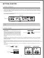
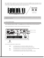
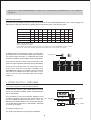
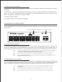
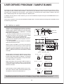
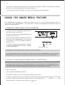
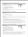
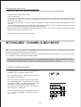
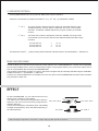
OWNER'S MANUAL
SMART MEDIA
SAVE
PARAMETER
LOAD
KEY & S CALE
CONTROL
MASTER
EFFECT
BLUE NOTE
GYPSY
WAV
MONITOR
LEVEL
DISTORTION
COMPRESSOR
LEVEL
DECIMATOR
PITCH S HIFTER
ARABIC
RING M OD.
ON
RESONATOR
MUTE
MINOR
PHASER
SAMPLE
FILTER
OFF
MAJOR
FLANGER
START POINT
I NPUT LEVEL
SCALE
SIGNAL
/ PEAK
TONE
TUNE / BPM
EXIT /
DELAY
MIN
WAH
REVERB
#
+
A
MAX
MIN
MAX
MASTER E Q
EDIT
B
B
A
LOW
HI
SELECT
G
END POINT
F
MAX
MIN
INPUT
E
REC
MIDI
SAVE
ENTER /
D
-
PRE
C
POST
KEY ASSI GN
MIN
+1
A
0
B
-1
C
OCTAVE
1
2
3
4
5
6
7
MIN
MAX
-24dB
+6dB
-24dB
NORMAL
+6dB
A
B
REVERSE
K.F. CURVE
8
MAX
M.F. RE VERSE
9
C
M.F. CURVE
10
MASTER FADER
PHONES
CONGRATULATIONS !
Thank you for purchasing the Vestax FADERBOARD. Please read this owner's manual carefully before
use so that you fully understand all of the special features and can enjoy full use of this product.
CONTENTS
IMPORTANT SAFEGUARDS ・・・・・・・・・・・・・・・・ 3
・・・・・・・・・・・・・・・・・・・ FEATURES-IN BRIEF
4
GETTING STARTED ・・・・・・・・・・・・・・・・・・・・ 5
7
CREATING AND PERFORMING ・・・・・・・・・・・・・・・ 10
USER DEFINED PROGRAM / SAMPLE BANKS ・・・・・・・ USING THE SMART MEDIA FEATURE ・・・・・・・・・・・ 12
・・・・・・・・・ SETTING MIDI CHANNEL & MIDI MODE
14
15
EFFECT ・・・・・・・・・・・・・・・・・・・・・・・・・・ ・・・・・・・・・・・・・・・・・・・・・ ERROR MESSAGE
17
18
APPENDI X ・・・・・・・・・・・・・・・・・・・・・・・・ 20
W ARRAN TY ・・・・・・・・・・・・・・・・・・・・・・・ SPECIFICATIONS ・・・・・・・・・・・・・・・・・・・・・ 20
CAUTION
RISK OF ELECTRIC SHOCK DO NOT OPEN
CAUTION : TO REDUCE THE RISK OF ELECTRIC SHOCK
DO NOT REMOVE COVER (OR BACK)
NO USER-SERVICEABLE PARTS INSIDE
REFER SERVICING TO QUALIFIED SERVICE PERSONNEL
The lightning flash with arrowhead symbol, within an equilateral triangle, is intended to alert
the user to the presence of uninsulated "dangerous voltage" within a product's enclosure
that may be of sufficient magnitude to constitute a risk of electric shock to persons.
The exclamation point within an equilateral triangle is intended to alert the user to the presence
of important operating and maintenance (servicing) instructions in the literature accompanying
the appliance.
TO REDUCE THE RISK OF FIRE OR ELECTRIC SHOCK, DO NOT
EXPOSE THIS APPLIANCE TO RAIN OR MOISTURE.
CAUTION : TO PREVENT ELECTRIC SHOCK, MATCH BLADE OF
PLUG TO WIDE SLOT, FULLY INSERT
ATTENTION : POUR EVITER LES CHOCS ELECTRIQUES,
INTRODUIRE LA LAME LA PLUS LARGE DE LA
FICHE DANS LA BORNE CORRESPONDANTE DE LA
PRISE ET POUSSER JUSQU' AU FOND
2
IMPORTANT SAFEGUARDS
READ BEFORE OPERATING EQUIPMENT
This product was designed and manufactured to meet strict quality and safety standards.
There are, however, some installation and operation precautions which you should be
particularly aware of.
1. Read Instructions-All the safety and operating instructions
should be read before the appliance is operated.
12. Power-Cord Protection-Power supply cords should be
routed so that they are not likely to be walked on or
squashed by items placed upon or against them, paying
particular attention to cords, plugs, attachments, other
receptacles, and the point where they exit from the
appliance.
2. Retain Instructions-The safety and operating instructions
should be retained for future reference.
3. Heed Warnings-All warnings on the appliance and in the
operating instructions should be adhered to.
13. Protective Attachment Plug-This appliance is equipped
with an overload protection device/plug. This is a safety
feature. See Instruction Manual for replacement or resetting
of protective device. If replacement of the plug is required,
be sure the service technician has used a replacement
plug that matches the specifications of the original plug.
4. Follow Instructions-All operating and use instructions should
be followed.
5. Cleaning-Unplug this product from the wall outlet before
cleaning. Do not use liquid cleaners or aerosol cleaners.
Use a damp cloth for cleaning.
14. Lightning-For added protection of this product during a
lightning storm, or when it is left unattended and unused
for long periods of time, unplug it from the wall outlet.
This will prevent damage to the product due to lightning
and power-line surges.
6. Attachments-Do not use attachments not recommended by
the product manufacturer as they may cause hazards.
7. Water and Moisture-Do not use this product near waterfor example, near a bath tub, wash bowl, kitchen sink, or
laundry tub, in a wet basement, or near a swimming pool,
and the like.
15. Overloading-Do not overload wall outlets and extension
cords as this can result in a risk of fire or electric shock.
8. Accessories-Do not place this product on an unstable
surface. The product may fall, causing serious injury to both
child or adult, and serious damage to the appliance.
Use only with a surface, or table recommended by the
manufacturer, or sold with this product. Any mounting of
the appliance should follow the manufacturer's instructions,
and should use a mounting accessory recommended by
manufacturer.
16. Object and Liquid Entry-Never push objects of any kind
into this product through openings as they may touch
dangerous voltage points or short-out parts that could
result in a fire or electric shock. Never spill liquid of any
kind on the product.
17. Servicing-Do not attempt to service this product yourself.
Opening or removing covers may expose you to dangerous
voltage or other hazards. Refer all servicing to qualified
personnel.
9. Ventilation-Slots and openings in the cabinet are provided
for ventilation ,to ensure reliable operation of the product
and to protect it from overheating, and these openings
must not be blocked or covered. The unit should never be
placed on an uneven surface(eg. bed) during operation.
This product should never be placed near or over a radiator
or heat register. This product should not be placed in a
built-in installation such as a bookcase or rack unless
proper ventilation is provided or the manufacturer's
instructions have been adhered to.
18. Damage Requiring Service-Unplug this product from
the wall outlet and refer servicing to qualified service
personnel under the following conditions:
a. When the power-supply cord or plug is damage.
b. If liquid has been spilled or objects have fallen into
this product.
c. If this product has been exposed to rain or water.
d. If this product does not function under normally
conditions Adjust only those controls that are
covered by this operating manual. An improper
adjustment of other controls may result in damage
and will likely require extensive work by a qualified
technician to restore the product to its normal
operation.
e. If this product has been dropped or the cabinet
has been damaged.
f. When the product exhibits a distinct change in
performance-this indicates need for service.
10. Power sources-This product should be operated only from
the type of power source indicated on the marking label. If
you are not sure of the type of power supply at the place of
use consult your appliance dealer or local power company.
11. Grounding or Polarization-This product is equipped with
a polarized alternating-current line plug (a plug having
one blade wider than the other). This plug will fit into the
power outlet only one way. This is a safety feature. If you
are unable to insert the plug fully into the outlet, try
reversing the plug. If this should still fail to fit, contact
your electrician to replace your obsolete outlet. Do not
defeat the safety purpose of the polarized plug.
3
19.Replacement Parts-When replacement parts are required,
be sure the service technician has used replacement
parts as specified by the manufacturer or which match
the specifications of original parts.
Unauthorized substitutions may result in fire, electric
shock or other hazards.
21.An appliance and cart combination should be moved with
care. Quick stops, excessive force, and uneven surfaces
may cause the appliance and cart combination to overturn.
20.Safety Check-Upon completion of any service or repairs
to this product, ensure that the service technician performs
a comprehensive safety check to determine that the
product is in correct functioning condition.
FEATURES - IN BRIEF
● The FADERBOARD is a visionary combination of melodic and percussive instruments with advanced
mixing, sampling and effects control features that offers a completely new and original approach to
creative music production and performance.
● The FADERBOARD utilizes faders, like that on a DJ mixing console, to create a feel similar to that of a
percussive instrument. These faders, justly named "KEY FADERS" produce sounds in a similar fashion
to a modern keyboard. However, due to the percussive nature of a fader, you need to move it up and
down to create sound, it is possible to produce extremely quick percussive patterns that would not
necessarily be possible with a keyboard.
● Like a mixing console, the FADERBOARD has a MASTER FADER (MF) which controls the output signal
to your sound system, mixer and or headphones. This MF can be reversed and the curve set to a normal,
sharp or flat setting.
● To give these "KEY FADERS" sound, the FADERBOARD has thirty (30) onboard Synthesizer Sounds,
ten (10) Drum / Percussion Sounds and up to ten (10) User Defined Sound Banks (Sample Banks).
● The entire "KEY FADER" registry can be assigned to several keys. These being; C,D,E,F,G,A or B. Further,
each of these assigned keys can be raised (#) by using the SHARP SWITCH. There is also a OCTAVE
SWITCH that allows you to switch to an octave one above and one below the standard middle C setting.
● In addition to the onboard sounds the FADERBOARD also allow for some serious production connections.
MIC INPUT, PHONO INPUT and LINE INPUT. These inputs can be used to produce samples (using the
User Defined Programs) or can allow the FADERBOARD to be used as a mixing console or effects unit.
● The FADERBOARD utilizes Smart Media (SM) technology. There is a SM Card slot on the rear panel
of the FADERBOARD that allows you to upload your own pre-produced samples or tracks. The SM
feature is able to read either WAV or AIFF data.
● To increase the production effectiveness of the FADERBOARD there is both a LINE OUTPUT and
MIDI OUTPUT.
● The MIDI OUTPUT on the FADERBOARD can be used to trigger external MIDI devices, such as a drum
machine or effects module, and can also be used to facilitate the recording or original materials.
● There are twelve (12) preset effects onboard the FADERBOARD. These include Wah, Reverb, Flanger,
Phaser, Ring modulation, Pitch shifter, Compressor, Distortion, Decimator, Resonator, Filter and Delay.
It is also possible to modify the parameters of each effect by using the EDIT VOLUME A and B.
● 2 Band MASTER EQ.
● Three (3) step monitor feature.
4
GETTING STARTED
1. GETTING CONNECTED
・ This device uses a DC power adaptor. First plug the adaptor into a ADAPTOR JACK and then plug the adaptor into
a power outlet. Make sure that the power outlet you are about to use corresponds with the information provided on
the face of the adaptor. Failure to plug this unit into the correct power supply may result in shock to users and
inoperability of this device.
・ If you are not using headphones use the LINE OUTPUT found on the rear panel of this device to connect to a suitable
mixer, amplifier or sound system.
<REAR PANEL>
POWER S WITCH
ADAPTOR JACK
LINE OUTPUT
Please be sure to turn off all the volumes of external devices such as amplifier when the main power is turned
on / off.
2. GETTING SOUNDS
・ Turn this device on. The POWER SWITCH is found on
MASTER
the rear panel.
Master Level. Set your master level to the desired level.
The master level essentially sets the volume for this device.
To the left of the MASTER LEVEL VOLUME is a MUTE
SWITCH. When mute is on, the LED above the switch
will light up. Whilst mute is active no sound will be
outputted.
LEVEL
MUTE
MASTER LEVEL VOLUME
MUTE S WITCH
MIN
MAX
・ MASTER FADER. Whereas the master level is set as above, the MASTER FADER (MF) controls the actual signal
output in an on/off and volume basis. In its primary position the MF produces sound as it moves away from the
farthest right setting.
MASTER FADER REVERSE. The MF can be reversed so that sound is produced as it moves from left to right. To
reverse the MF use the MF REVERSE SWITCH located on the top panel above the MF. You can also set the curve on
the MF.
There are three (3) settings to choose from. Curve A is a flat slope; curve B is a normal slope and curve C is
sharp slope.
NORMAL
M.F. RE VERSE S WITCH
A
M .F. RE VERSE S WITCH
“NORMAL”POSITION
B
REVERSE
M.F. RE VERSE
C
M .F. RE VERSE S WITCH
“REVERSE”POSITION
M.F. CURVE
NORMAL
A
NORMAL
B
REVERSE
M.F. RE VERSE
A
B
REVERSE
C
M.F. CURVE
M.F. RE VERSE
C
M.F. CURVE
MASTER FADER
MASTER FADER
MAX
MASTER FADER
5
MASTER FADER
CUT
CUT
MAX
・ KEY FADER Position. Depending on the sound setting is how the KEY FADERS will work. Essentially the KEY
FADERS are an on/off signal for a particular sound, much like that on a modern keyboard/synthesizer. As you
move the KEY FADER up (towards the rear panel) you will produce sound.
MAX
1
2
3
4
10
MASTER E Q
LOW
-24dB
HI
+6dB
-24dB
+6dB
MATER E Q VOLUME
MIN
KEY FADER 1 ~ 10
Please take care when setting the level on your FADERBOARD, mixer and amplifier to avoid any kind of damage
to listeners or equipment.
3. USING HEADPHONES
・ To use headphones first plug a suitable pair of headphones into the HEADPHONE JACK and set the monitor level
using the MONITOR LEVEL VOLUME. The HEADPHONE JACK is located on the front panel of this device.
・ Using the MONITOR SELECT SWITCH select the desired signal to be heard.
SMART MEDIA
SAVE
PARAMETER
LOAD
KEY & S CALE
CONTROL
MASTER
EFFECT
BLUE NOTE
GYPSY
WAV
COMPRESSOR
MONITOR
LEVEL
DISTORTION
PITCH S HIFTER
ARABIC
LEVEL
DECIMATOR
ON
RESONATOR
RING M OD.
MUTE
MONITOR LEVEL VOLUME
MINOR
PHASER
SAMPLE
FILTER
DELAY
FLANGER
START POINT
OFF
MAJOR
I NPUT LEVEL
SCALE
SIGNAL
/ PEAK
TONE
TUNE / BPM
EXIT /
#
+
MIN
WAH
REVERB
MIN
MAX
MASTER E Q
EDIT
B
B
A
A
MAX
LOW
SELECT
HI
G
END POINT
F
MAX
MIN
INPUT
E
REC
MIDI
SAVE
ENTER /
D
-
PRE
C
MONITOR SE LECT S WITCH
POST
KEY ASSI GN
MIN
+1
2
3
4
5
6
7
MAX
A
0
-24dB
+6dB
-24dB
NORMAL
B
-1
K.F. CURVE
8
+6dB
A
B
REVERSE
C
OCTAVE
1
MIN
MAX
M.F. RE VERSE
9
C
M.F. CURVE
10
MASTER FADER
PHONES
n
HEADPHONE JACK
There are three settings INPUT, PRE and POST.
INPUT
This setting allows you to monitor any PHONO, LINE or MIC
sources that have been connected to the rear panel of this device.
PRE
This setting allows you to monitor all sources regardless of the position of the MF.
POST
This setting allows you to monitor the master output signal.
Thus the position of the MF will influence what you are able to monitor.
6
CREATING & PERFORMING
As mentioned before, the FADERBOARD incorporates melodic and percussive elements to create a new and exciting
instrument with advanced mixing, sampling and effects control features.
1. SETTING A TONE/SOUND/PROGRAM
Tone. To set a tone press the TONE SWITCH. When
pressed the TONE LED will light up.
PARAMETER
CONTROL
DISPLAY
Select a Tone. Using the CONTROL FADER select a tone.
It is also possible to set a tone by using the EXIT / +
SWITCH and ENTER / - SWITCH.
TONE LED
TONE
TUNE / BPM
+
EXIT /
CONTROL FADER
TONE S WITCH
There are thirty (30) preset Synth Programs (sounds),
ten (10) preset Drum kits / Percussion Programs and
ten (10) User Definable Program banks.
MIDI
SAVE
ENTER /
EXIT / + S WITCH
-
ENTER / - S WITCH
Before being able to use a User Definable Program bank
you must first record a sample. If there are no user banks
currently recorded then the DISPLAY will show 0.
<DISPLAY>
Synth Programs
・There are thirty (30) preset Synth Programs available.
・Typically, a synth sound may be used like a modern day synthesizer.
That is, each KEY FADER will have a corresponding musical note/tone
(like a keyboard) that is subject to the current scale/key setting.
・For more information please turn to page 18.
Drumkits /
Percussion Programs
・There are ten (10) preset Drum kits / Percussion Programs available.
・Typically, each KEY FADER will control a different sound and will work
as a trigger for the sound in an on/off sense.
・For more information please turn to page 18.
User Definable
Program banks
・The User Defined Program banks allows for up to ten (10) samples to
be recorded up to a maximum size of thirty (30) seconds.
・Once recorded a sample can be played back by using the KEY FADERS.
The root KEY FADER will play back the original version of the sample
whilst each KEY FADER 'above' the root KEY FADER will play back the
sample at an advanced pitch.
・For more information please turn to page 10.
S.01 S.30
<DISPLAY>
d.01 d.10
<DISPLAY>
U.01 U.10
2. SETTING THE ROOT KEY AND THE SCALE.
There are seven (7) major scales / keys to select from on the FADERBOARD. Each of these can be further raised ♯
by a semitone.
SETTING THE ROOT KEY (BASIC KEY OF SCALE)
Setting Root Key of the Scale.
When you press KEY ASSIGN SWICH (C~B), the LED
lights and the key assigned to KEY FADER 1.
KEY & S CALE
BLUE NOTE
GYPSY
ARABIC
SCALE SE LECT S WITCH
MINOR
MAJOR
You can select a different scale / key mid play. The output
signal will change instantly.
SCALE
#
B
A
G
F
When you press ♯, the LED lights and the root key turns
into ♯. To release ♯ setting, press ♯ again or press the
other KEY ASSIGN SWITCH.
E
D
C
KEY ASSI GN
7
KEY ASSI GN S WITCH
There is no ♭ in KEY ASSIGN SWITCH. In order to set ♭, please select ♯ SWITCH from C∼B in reference
to page 18.
SETTING THE SCALE
There are five (5) possible scale types that may be selected on the FADERBOARD. Major, Minor, Arabic, Gypsy and
Blue Note. For specific information regarding these scales plase refer to the following chart.
1
2
3
4
5
6
7
8
9
10
MAJOR
C
D
E
F
G
A
B
C
D
E
MINOR
C
D
E♭
F
G
A♭
B♭
C
D
E♭
ARABIC
C
D♭
E
F
G
A♭
B
C
D♭
E
GYPSY
C
D
E♭
F♯
G
A♭
B
C
D
E♭
BLUE NOTE
C
D
E♭
F
G♭
A
B♭
C
D
E♭
ARABIC(Double Harmonic Scale)
GYPSY(Hungarian Minor Scale)
Unfortunattely it is not possible to select either harmonic or melodic minor on the FADERBOARD. In order to achieve
this scale type, please use the SHARP (♯) SWITCH to affect the 6th and 7th notes as and when required.
In addition to each root octave of the seven (7) scales / keys
and variants the OCTAVE SWITCH allows you to adjust up
one octave or down one octave. In combination with a synth
sound it is possible to produce highly melodic compositions.
+1
A
0
B
OCTAVE S WICTH
-1
C
OCTAVE
7
K.F. CURVE
8
9
10
If you make a change to either the key/scale type or the
octave the output signal will reflect this change immediately.
There are only eight (8) tones to a normal scale in any
given octave. As there are ten KEY FADERS on the
FADERBOARD following a complete octave progression
there will be an additional two full tonal steps. This is
only the case for Synth Programs and User Defined
Programs.
3. SETTING THE PITCH / TEMPO (BPM)
* For Synth Programs & User Defined Programs
To set the pitch use the TUNE / BPM SWITCH located
next to the CONTROL FADER. When activated the LED
will be illuminated.
Once activated, by using the CONTROL FADER you will
be able to increase or decrease the playback speed of
any KEY FADER controlled sound by up to ± 100%. The
adjustment mechanism allows for 2% incremental changes.
You are also able to use the EXIT / + and ENTER / - SWITCHS
to control the changes.
PARAMETER
CONTROL
TONE
TUNE / BPM
EXIT /
+
TUNE / BPM S WITCH
EXIT / + S WITCH
MIDI
SAVE
ENTER /
-
ENTER / - S WITCH
The primary setting is 0%.
Any change will affect the output signal immediately.
8
* For Drum / Percussion Programs
To set the tempo use the TUNE / BPM SWITCH located next to the CONTROL FADER. When activated the LED will be
illuminated.
Once activated, by using the Control fader you will be able to increase or decrease the BPM of your drum/percussion
loop by up to ± 100%. The adjustment mechanism allows for 2% incremental changes. You are also able to use the
EXIT / + and ENTER / - SWITCHS to control the changes.
The primary setting is 0 BPM.
Any change will affect the output signal immediately.
4.ADJUSTING THE FADER CURVES
On the FADERBOARD both the MASTER FADER and the KEY FADERS curves can be adjusted to suit your preferred
playing style.
KEY FADER CURVE SE LECT S WITCH MASTER FADER CURVE SE LECT S WITCH
+1
A
0
B
-1
C
OCTAVE
1
2
3
4
5
6
7
NORMAL
K.F. CURVE
8
A
B
REVERSE
M.F. RE VERSE
9
C
M.F. CURVE
10
MASTER FADER
PHONES
KEY FADER CURVE CONTROL
To set the KEY FADER Curve to your playing style use the K.F. CURVE SWITCH. When you make a selection, the
entire KEY FADER registry is affectedimmediately. There are three (3) curve settings for the KEY FADERS. Each of
these settings will affect how the fader not only activates the sound but how it also controls the volume of that sound.
A
To set the KEY FADER curve to your playing style use the K.F. CURVE switch. When you make a
selection, the entire KEY FADER registry is affected immediately.
B
The smoothest setting, a type B curve is a gentle and gradual curve from open to full open.
C
This curve becomes fully open very quickly. This setting is best when you are attempting to create
staccato/percussive fader moves.
MASTER FADER CURVE CONTROL
To set the MASTER FADER Curve to your playing style use the M.F. CURVE SWITCH. When you make a selection the
M.F. curve shape will change immediately. There are three (3) curve settings for the KEY FADERS. Each of these
settings will affect how the fader not only activates the sound but how it also controls the volume of that sound.
A
This setting will open slowly at first and then open quite quickly as the faders gets close to its
full open point.
B
The smoothest setting, a type B curve is a gentle and gradual curve from open to full open.
C
This curve becomes fully open very quickly. This setting is best when you are cutting quickly.
9
USER DEFINED PROGRAM / SAMPLE BANKS
Essentially the User Defined Programs are onboard sample banks that you can use to record onto by using the various
input options (LINE, PHONO, MIC) available. There are ten (10) available banks to which a maximum of thirty (30)
seconds worth of samples can be recorded. These samples can be played back using the KEY FADERS, with each
KEY FADER playing back the original sample at a different pitch.
In addition to being able to record onboard, you can record additional samples through the FADERBOARD onto a
Smart Media Card.
There are a maximum of ten (10) User Definable sample banks. The total onboard recording space available cannot
exceed thirty (30) seconds.
1. RECORDING A SAMPLE
・ Connect your external source, from which you want to
sample, to the FADERBOARD and select that input
using the INPUT SELECT SWITCH on the rear panel
of the FADERBOARD. There is 1 x LINE INPUT, 1 x PHONO
INPUT and 1 x MIC INPUT.
・If using a turntable make sure your connection to
the phono terminal is also grounded. Use the GND
TERMINAL provided on the FADERBOARD.
・In addition to any external source you can record a
sample from the onboard Synth Programs or Drum /
Percussion Programs.
・It is also possible to record a sample of combined
external and internal sources.
PHONO I NPUT
GND TERMI NAL
MIC I NPUT
INPUT SE LECT S WITCH
LINE I NPUT
SIGNAL / PEAK LED
SMART MEDIA
SAVE
PARAMETER
LOAD
WAV
CONTROL
SAMPLE
START POINT
I NPUT LEVEL
SIGNAL
/ PEAK
・ INPUT LEVEL VOLUME. If you have connected an
external device make sure that you set the input level
correctly to avoid overload of the circuitry. The
SIGNAL / PEAK LED will flash if your input level is to
high. To adjust the input level use the INPUT LEVEL
VOLUME.
MIN
END POINT
REC S WITCH
・ Standby Mode. Push the REC SWITCH once to set the
EXIT /
MIDI
SAVE
ENTER /
+
SAVE S WITCH
-
SAVE LED
INPUT LEVEL VOLUME
REC LED : Flash
sample function to standby. When in standby mode
the REC LED and the DISPLAY will flash. If you want to
exit from standby mode and NOT record, press either
the TONE or EWIT / + SWITCH.
TUNE / BPM
MAX
REC
REC LED
TONE
DISPLAY : Flash
REC
・ Begin Recording. Press the REC SWITCH again to
REC LED : Illuminate
start recording your sample. When you are recording
a sample the REC LED will be illuminated and the
DISPLAY will flash.
DISPLAY : Flash
REC
・ End Recording. Press the REC SWITCH once more.
SAVE LED : Flash
When this is done the SAVE LED will start flashing and
the DISPLAY will show an illuminated "U".
DISPLAY : Illuminate
SAVE
By ending the recording process you have managed to record a sample. This sample is not yet saved to a User
Defined Program bank. You can listen to your sample by using the KEY FADERS before you save it.
10
2. SAVING A SAMPLE
・ Once you have recorded a sample you are able to play it back by using the KEY FADERS. To check the quality of
your sample, first make sure that you have lowered the volume of your external source to a suitable level or turned
this external source off. Please note that if the OCTAVE SWITCH is not set to '0' then playback of your sample will
not sound the same as your external source.
・ Saving. If you are happy with your sample press the SAVE LED. By pressing the SAVE LED, the FADERBOARD will
look for the lowest numbered availabe User Defined Program Bank to save to. This bank number will be displayed
on the DISPLAY. You can also select a preferred number, assuming it is available by using the CONTROL FADER.
If a User Defined Program Bank is empty there will be a dot following the number. (As illustrated).
SAVE LED : Illuminate
You can overwrite a pre-recorded program bank so
pleas take care when selecting a preferred bank
number.
DISPLAY : Flash
SAVE
・ Once an available or desired User defined program bank number is selected
a dot following the number
press the ENTER / - SWITCH to complete the saving process. Once pressed the
DISPLAY will flash. When the saving is completed the DISPLAY will stop flashing.
・ This sample that you have now recorded can be used over and over again by selecting the appropriate bank
number and then using the KEY FADERS to control output.
To access a User Defined Program / Sample press the TONE SWITCH and then select from the program banks
available. You can use either the CONTROL FADER or the EXIT / - and ENTER / + SWITCH to select an available program.
3. SETTING THE START AND END POINTS FOR A SAMPLE
The start and end points of any given sample can be
adjusted according to your needs. To control the start
and end points use the START POINT / END POINT
FADERS.
SMART MEDIA
LOAD
SAVE
PARAMETER
WAV
CONTROL
SAMPLE
START POINT
I NPUT LEVEL
SIGNAL
/ PEAK
START POINT FADER
END POINT
END POINT FADER
MIN
TONE
TUNE / BPM
EXIT /
MIDI
SAVE
ENTER /
+
MAX
REC
-
・ Select an appropriate sample and start it playing by using the KEY FADERS. To adjust the start point move the
START POINT FADER. An initial movement from left to right (assuming the fader is set to its full position) will result
in the sample starting from a point after which it was recorded. Adjustments to the end point can be made in the
same manor but will work from right to left. It is also possible to reverse your sample by moving the start point all
the way to the right and the end point all the way to the left.
・ Saving start and end point adjustments. When the start or end point of a sample is altered the SAVE LED will flash.
To save these changes press the SAVE SWITCH and select the appropriate User Defined Program bank to save to.
・ Once an available or desired User Defined Program bank number is selected press the ENTER / + SWITCH to complete
the saving process. Once pressed the DISPLAY will flash. When the saving is completed the DISPLAY will stop flashing.
When you change or renew the play range on the User Defined Program and save it, the other space will
automatically be deleted. If you do not wish to save at all, Please use another bank.
4. DELETING A USER DEFINED PROGRAM BANK
・ Select the User Defined Program to be deleted by using the CONTROL FADER or the EXIT / - and ENTER / + SWITCHS.
・ Press the TONE and SAVE SWITCHS simultaneously to start deleting the selected program bank. The program
bank chosen will flash.
11
・ Press enter to complete the deletion process. Once pressed the DISPLAY will flash. When deleting is completed
the DISPLAY will stop flashing and the User Defined Program.
If a User Defined Program is available, thus empty, a dot will follow the number displayed.
USING THE SMART MEDIA FEATURE
The FADERBOARD is equipped with a Smart Media feature that you can save User Defined Programs that you
have created on the FADERBOARD to. You are also able to read files, in the applicable formats (WAV, AIFF) to be
used in your creation process.
1. FORMATTING SMART MEDIA FOR THE FADERBOARD
・ To be able to use the Smart Media (SM) feature you
first need to format your SM card.
・ Insert your SM Card into the SMART MEDIA SLOT
provided on the rear panel.
・ Press the SMART MEDIA SAVE SWITCH located at
SMART MEDIA SLOT
the top left of the FADERBOARD. If your card is not
yet formatted or incorrectly installed the DISPLAY
will show『 For 』.
SMART MEDIA
SAVE
LOAD
WAV
・ To continue formatting press the ENTER / - SWITCH.
To end the formatting process pres the EXIT / + SWITCH
or remove the SM Card
SMART MEDIA SAVE SWITCH
Formatting your Smart Media Card will erase any previously saved data.
If your Smart Media Card was formatted on anything other than the FADERBOARD, it is likely that the
FADERBOARD will not be able to read your data. Please format your Smart Media Card on the FADERBOARD.
2. SAVING ALL USER DEFINED PROGRAM BANKS TO SMART MEDIA
You are only able to trasnfer ALL User Defined Programs / samples created on the FADERBOARD to your
Smart Media Card. When transferring all User Defined Programs / sample banks to your SM Card, ensure that
you have more than 1152KB of available storage capacity prior to commencing your transfer.
・ Insert your SM Card.
・ Press the SMART MEDIA SAVE SWITCH
・ The DISPLAY will show the current User Defined Program bank numbers.
・ To select an appropriate bank use the CONTROL FADER. When saving a User Defined Program to a SM card,
the DISPLAY will show User Defined Program numbers in the following manner. 『 -1-』= EMPTY, 『 [1] 』=FULL
・ Press the ENTER / - SWITCH to begin saving to your SM Card.
12
3. READING ALL AVAILABLE SAMPLE FILES FROM SMART MEDIA
・ Insert your SM Card.
SMART MEDIA
SAVE
・ Press the SMART MEDIA LOAD SWITCH.
LOAD
WAV
・ The DISPLAY will show the programs available.
SMART MEDIA LOAD SWITCH
・ Press the SMART MEDIA LOAD SWITCH again.
『 ALL 』will be displayed on the DISPLAY and the
LED will be illuminated.
・ Press the ENTER / - SWITCH and reading will commence. Once pressed the DISPLAY will flash. Upon completion,
the DISPLAY will stop flashing.
4. READING ONE SAMPLE FILE FROM SMART MEDIA
・ Insert your SM Card.
・ Press the SMART MEDIA LOAD SWITCH.
・ The DISPLAY will show the programs available.
・ Press the SMART MEDIA LOAD SWITCH again. 『 ALL 』will be displayed on the DISPLAY and the LED will be
illuminated.
・ Using the CONTROL FADER select the appropriate program number to be read. Once selected the SAVE LED
will be illuminated.
・ Press the SMART MEDIA LOAD SWITCH once more and the selected file will start being read.
*** If you press the SMART MEDIA LOAD SWITCH again the file will be played back.
・ To save the SM sample file press the SAVE SWITCH. The lowest available onboard space will be selected and
then displayed or you can select another program space (if available) by using the CONTROL FADER.
・ Press the ENTER / - SWITCH to complete the reading & then saving of this SM sample file. Once pressed the
DISPLAY will flash. When this process is completed the DISPLAY will no longer be flashing.
5. READING A WAV or AIFF FILE FROM SMART MEDIA
・ Insert your SM Card.
SMART MEDIA
SAVE
・ Press the SMART MEDIA WAV SWITCH.
LOAD
WAV
・ Select an appropriate file by using the CONTROL FADER.
Once selected the SAVE LED will start flashing.
SMART MEDIA WAV SWITCH
・ Press the WAV SWITCH again and the sile will be read
into the FADERBOARD and ready for playback. By
pressing the WAV SWITCH again, this file will be
played back.
・ To save the SM sample file press the SAVE SWITCH. The lowest available onboard space will be selected and then
displayed or you can select another program space (if available) by using the CONYROL FADER.
・ Press the ENTER / - SWITCH to complete the reading & then saving of this SM sample file. Once pressed the
DISPLAY will flash. When this process is completed the DISPLAY will no longer be flashing.
13
CREATING WAV & AIFF FILES
In order to use a WAV or AIFF file on the FADERBOARD the following conditions must be satisfied.
・ File type must be either WAV or AIFF
・ 8 Bit or 16 Bit mono
・ The file must be named 00 ~ 99.wav or 00 ~ 99.aif. That is, if the file is to be titled 1 then the file name must be
01.wav or 01.aif. If by chance you have awarded both a WAV and an AIFF file the same number/name, the WAV
file will take precedence.
・ The volume level of a WAV or AIFF file cannot be adjusted. This level needs to be determined during the creation
of the file.
・ To have a sample play back at its creation pitch rate it must be created at 32Hz. If created outside this Hz range,
you will need to adjust the playing pitch with the FADERBOARD.
・ Both WAV and AIFF will assume the following parameters, 8 bit / 32 KB, 16 bit / 64 KB. A sample should take
approximately one (1) second to be read.
Smart Media is a Toshiba licensed technology.
SETTING MIDI CHANNEL & MIDI MO DE
MIDI is an acronym for Musical Instrument Digital Interface. A MIDI device works in a similar way to a television.
That is, if the receiving device and the transmitting device are both set to the same channel then the transmitted
information can be monitored on the receiving device.
On the FADERBOARD, the MIDI output can be used to transmit data to an external device, such as a drum machine,
PC or sampler, so long as that device is MIDI capable.
When synchronizing an external MIDI device to the FADERBOARD, please read the user manual / guide
provided with your external device in order to ensure that your synchronization is effective.
1. SETTING THE MIDI CHANNEL
・ Connect the MIDI OUTPUT on the FADERBOARD to
the MIDI input of your external MIDI device.
・ Press the MIDI SWITCH. When MIDI is active the
MIDI LED will be illuminated.
MIDI OUTPUT
・ There are sixteen (16) MIDI channels to select from
on the FADERBOARD. To make a selection use the
CONTROL FADER. Your external MIDI device will
determine the channel needed to be selected.
Once the correct channel has been identified the
SAVE LED will be illuminated.
PARAMETER
CONTROL
・ Press the SAVE SWITCH and the DISPLAY will show
『 - 』Press the ENTER / - SWITCH to set the
MIDI channel.
TONE
TUNE / BPM
EXIT /
MIDI
SAVE
ENTER /
MIDI SWITCH
14
+
-
2. MIDI MODE SETTINGS
・ Pressing MIDI SWITCH for one (1) second, MIDI mode comes to effective.
・ Select the note number for output format either『 nt1 』or『 nt2 』by CONTROL FADER.
『 nt1 』
The note number created under the setting of OCTAVE SWITCH, KEY
ASSIGN SWITCH, SCALE SELECT SWITCH will come out from MIDI
OUTPUT. CONTROL FADER adjusts the program (TONE) of the MIDI
receiver.
『 nt2 』
The fixed note number is assigned to each KEY FADER. The range of the
note number is from 35 to 64 and OCTAVE SWITCH determines their range
as below.
・OCTAVE SWITCH
・OCTAVE SWITCH
・OCTAVE SWITCH
-1
0
+1
35∼44
45∼54
55∼64
・ The DISPLAY shows『 - 』after pressing SAVE SWITCH and MIDI mode is set with ENTER / + SWITCH on.
READ ONLY PROGRAM
In order to allow you to use the various effects and other features on the FADERBOARD for a sound source originating
from an external MIDI device, there is a Read Only Program. This program allows you to control the output source
from an external MIDI device through the FADERBOARD.
This program is found after program d.10 (Drum / Percussion Program #10) and is easily selected using the CONTROL
FADER or the EXIT / - and ENTER / + SWITCHS.
Connect your external MIDI device to the MIDI out on the rear panel of the FADERBOARD and then select the Read
Only Program to begin use.
EFFECT
On the FADERBOARD, you can select and use one of
twelve types of effect for each pattern.
The effect can be selected by using EFFECT SELECT
SWITCH, and can be turned on/off by using EFFECT
ON/OFF SWITCH.
Use the two knobs (EDIT VOLUME A, EDIT VOLUME B)
to adjust the parameters, which will differ depanding on
the selected effect.
EFFECT
DISTORTION
COMPRESSOR
PITCH SHIFTER
EFFECT SELECT SWITCH
DECIMATOR
RING MOD.
ON
RESONATOR
PHASER
EFFECT ON/OFF SWITCH
FILTER
FLANGER
OFF
DELAY
WAH
REVERB
EDIT
B
A
EDIT VOLUME B
EDIT VOLUME A
MIN
Some time may be required for the effect to begin applying when you switch patterns.
15
MAX
MIN
MAX
EFFECT TYPES AND PARAMETERS
REVERVE
This simulates the reverberation and acoustics of a plate reverb unit.
EDIT A <TIME>
The reverb time will lengthen as the knob is rotated toward the right.
EDIT B <LEVEL>
The level of the reverberation will increase as the knob is rotated toward the right.
FLANGER
Flanger and chorus are effects that modulate the pitch of a slightly time-delayed copy of the sound and add it to the
original sound to create a sence of spaciousness, modulation, and vibrato.
EDIT A <LFO RATE>
Adjusts the LFO speed of flanger/chorus. The LFO speed will become faster as
the knob is rotated toward the right.
EDIT B <DEPTH>
Adjusts the depth of flanger/chorus effect. The effect will change from chorus
to flanger as the knob is rotated toward the right.
PHASER
This effest adds modulation to the sound by mixing a cyclically phase-shifted sound with the original sound.
EDIT A <LFO RATE>
Adjusts the LFO speed of the phaser. The LFO speed will become faster as the
knob is rotated toward the right.
EDIT B <DEPTH>
Adjusts the depth of phaser. The modulation will become greater as the knob is
rotated toward the right.
RING MOD. (ring modulation)
This effect applies modulation to the sound in order to create metallic resonances or unusual sound effects.
EDIT A <FREQUENCY>
Specifies the frequency of the modulation that will be applied. The frequency will
rise as the knob is rotated toward the right.
EDIT B <BALANCE>
Specifies the balance of the effect sound and direct sound. As the knob is rotated
toward the right, the effect sound will increase and direct sound will decrease.
PITCH SHIFTER
This effect shifts the pitch.
EDIT A <PITCH>
Specifies the amount of pitch shift. When the knob is in the center position, the
output pitch will be the same as input pitch. As the knob is rotated toward the
left the pitch will become lower, and as the knob is rotated toward the right the
pitch will become higher.
EDIT B <DRY LEVEL>
This adds the original sound to the pitch-shifted sound. As the knob is rotated
toward the right, increasing amounts of the original sound will be added to the
effect sound.
COMPRESSOR
A compressor boosts low level sounds and reduces high level sounds in order to minimize differences in volume and
make the sound more consistent.
EDIT A <SENSITIVITY>
Specifies the sensitivity of the compressor. When the knob is in the far left position,
there will be no effect. As the knob is rotated toward the right, the effect will apply
more strongly.
EDIT B <ATTACK>
Specifies the attack speed until the compressor begins to take effect. The attack
will become slower as the knob is rotated toward the right.
DISTORTION
By boosting the volume appropriately, thi effect causes the sound to distort and produces a rich overtone structure.
EDIT A <GAIN>
Specifies the degree of distortion. The sound will be distorted more greatly as the
knob is rotated toward the right.
EDIT B <LEVEL>
Adjust the output level. The output level will increase as the knob is rotated toward the right.
16
DECIMATOR
This effect lowers the sampling frequency and the number of sampling bits, producing a grainy sound
characteristic of cheao samplers.
EDIT A <SAMPLING FREQUENCY>
Rotating the knob toward the right produces a more lo-fi sound, and rotating it
toward the left produces a more hi-fi sound.
EDIT B <NUMBER OF SAMPLING BITS>Rotating the knob toward the right will produce a sound typical of fewer bits (lo-fi),
and rotating it toward the left will produce a sound typical of more bits (hi-fi).
RESONATOR
This adds a specific frequency region to the original waveform that has been boosted by a band pass filter
EDIT A <CUTOFF FREQUENCY>
This adjusts the cutoff frequency of the band pass filter. The cutoff frequency will
rise as you turn the knob toward the right.
EDIT B <RESONANCE>
This boosts the sound in the region of the cutoff frequency, adding a distinctive
character to the sound. The resonance will increase as you turn the knob toward
the right.
FILTER
This is a low pass filter with resonance. It cuts the overtones that are above the cutoff frequency, producing
a milder tone.
EDIT A <CUTOFF FREQUENCY>
Adjusts the cutoff frequency of the low pass filter. The cutoff frequency will rise as
you turn the knob toward the right.
EDIT B <RESONANCE>
This emphasizes the sound in the region of the cutoff frequency, adding a distinctive
character to the sound.
DELAY
This is a Delay with delay time and feedback.
EDIT A <TIME>
Adjusts the delay time (11 ms ~ 2048 ms). The delay time will be long as you turn
the knob toward the right.
EDIT B <FEEDBACK / LEVEL>
Adjusts the level of the delay sound and the amount of feedback (the number of
deray repeats). Rotating the knob toward the right will increase the level of delay
sound, and will also increase the amount of feedback.
WAH
The cutoff frequency is controlled by LFO.
EDIT A <LFO RATE>
Adjusts the LFO speed of the cutoff frequency. The LFO speed will rise as you turn
the knob toward the right.
EDIT B <CUTOFF FREQUENCY>
Adjusts the cutoff frequency. The cutoff frequency will rise as you turn the knob
toward the right.
ERRO R MESSAGE
Er.1
Data is unable to be read.
Er.3
There is insufficient memory on your Smart Media (SM) Card. To use the SM feature on the FADERBOARD
you must have a SM Card with more than 4 MB of storage space.
Er.4
Unable to read SM content. This may because the file type is incompatible with the FADERBOARD.
The FADERBOARD is able to read both WAV and AIFF files.
Er.7
Error during saving to Smart Media. Please try again.
Er.8
No Files Found. Either your SM Card is empty or the SM Card is corrupt.
Er.9
Can't access data. SM Card protective seal is still intact.
17
APPEN DIX
Fig.1 SYNTH PROGRAMS
S.01 : Saw-Pro Synth
S.11 : DWGS Digital
S.21 : M1 Pick Bass
S.02 : Pulse 25%-MG
S.12 : 5th Sine
S.22 : Slap Bass Mix
S.03 : Square
S.13 : 5th Square
S.23 : M1 Organ
S.04 : Triangle-MG
S.14 : Sync Tri-MS2k
S.24 : DWGS Clav
S.05 : Pure Sine
S.15 : HPF Sweep-MS2k
S.25 : Voice VS
S.06 : Sine Kick Bass
S.16 : Cyber Bass-Z1
S.26 : Pad Chord maj7
S.07 : Dark Bass
S.17 : Ring Bass-MS2k
S.27 : M1 Piano Chord Set
S.08 : Additive Sine
S.18 : Vibrato Sine
S.28 : E.P. Chord Set
S.09 : DWGS Bell
S.19 : NRG Hit
S.29 : Guitar Chord Set
S.10 : Square Oct Mix
S.20 : Ac.Bass
S.30 : Noise
Synth Program S.27, S.28 and S.29 are Chord based programs. Using the OCTAVE SWITCH
may effect the balance of these programs and may result in the loss of the highest note in a
chord due to that particular note not being available.
Fig.2 DRUM KITS / PERCUSSION PROGRAMS
KEY FADER 1
KEY FADER 2
KEY FADER 3
KEY FADER 4
KEY FADER 5
KEY FADER 6
KEY FADER 7
KEY FADER 8
KEY FADER 9
KEY FADER 10
Bass Drum 1
Bass Drum 2
Snare 1
Snare 2
Hihat 1
Hihat 2
Kit 1
Kit 2
Sound 1
Sound 2
d.01 : OG
BD-Dark
BD-99 Dist 1
SD-Dry 4
SD-R&B 4
HH-88 Cl
HH-88 Op
SD-88 Rim
HH-Std 1 Op
HH-Big Chunk Cl
HH-Big Chunk Op
d.02 : Bump
BD-99 1
BD-99 2
SD-Ambi 2
SD-Dry 2
HH-Std 1 Cl
HH-Std 2 Cl
Ride-Edge 2
Zap 1
Synth SE-2
Reverse-BD
BD-99 Dist3
BD-Dry 2
SD-88 2
SD-Ambi 1
Cabasa-Normal
HH-Old Cl
Crash-99
Crash-Normal
Tom-99
Tom-88
BD-88 1
BD-88 2
Clap-99
SD-88 1
HH-99 Cl
HH-99 Op
Reverse-SD 1
Reverse-Crash
Claves
Reverse-SD 2
BD-Dry 4
BD-Squash
SD-R&B 1
SD-Rim 2
HH-Crisp Cl
HH-R&B Cl
Bongo-Hi Op
Bongo-Slap N5
Bongo-Lo Op
Bongo-Lo N5
d.06 : New Jack
BD-Defness
BD-Defness/OHH
SD-Hip
SD-R&B 3
HH-Crisp Op
HH-Std 2 Op
Ride-99
BD-Dry 2
SD-77
SD-Disco
d.07 : Fun House
BD-Analog
BD-ZAP
Clap-88
SD-99 1
Tambourine-Acc
HH-Old Op
Agogo
Synth Perc 1
Cowbell
Cha Cha Bell
d.08 : Rough
BD-Jungle
BD-99 Dist 2
SD-Jungle
SD-Piccolo 2
Ride-Edge 1
Tom-Std Hi
Tom-Std Lo
Tom-Std Floor
Tom-Jazz Hi Rim
Tom-Jazz Hi
d.09 : Tabla
BD-Dry 2
Taiko-Rim
Tabla-Na
Tabla-Tin
Tabla-Mute 1
Tabla-Mute 2
Tabla-Baya Mute 2
Cabasa-Dist Up
Cabasa-Dist Down
Tsuzumi
d.10 : Conga
Conga-Hi Slap 1
Conga-Hi Slap 2
Conga-Hi MtSlap
Conga-Lo Slap
Conga-Lo Slap N5
Conga-Lo MtSlap
Cabasa-EXB
Guiro-Long
Samba Whistle
Udu
d.03 : Tight
d.04 : Mirror Shaker
d.05 : Smoov
Following the Drum / Percussion Program d.10 is Read Only MIDI Program.
Fig.3 ROOT KEY QUICK REFERENCE
1/2 STEP
1
2
3
4
5
6
7
8
9
10
11
12
13
14
ROOT KEY
C
C♯
D
D♯
E
E♯
F
F♯
G
G♯
A
A♯
B
B♯
SUBSTITUTE
ー
D♭
ー
E♭
ー
F
ー
G♭
ー
A♭
ー
B♭
ー
C
Fig.4 EFFECTS OF THE OCTAVE SWITCH ON THE KEY FADERS
KEY FADER
1
2
3
4
5
6
7
8
9
10
Fig.5 BPM PARAMETERS
BPM Range
0
OCTAVE:+1
C
D
E
F
G
A
B
C
D
E
OCTAVE:0
C
D
E
F
G
A
B
C
D
E
OCTAVE:-1
C
D
E
F
G
A
B
C
D
E
18
Increment of Change
20
20
20
30
5
30
170
1
170
240
2
240
400
5
400
800
10
800
999
100
MIDI Implementation Chart
FADERBOARD
Transmitted
Recognized
1−16
1−16
×
×
×
×
×
Altered
**********
×
35−88
×
number:
True voice
**********
×
Velocity
Note
ON
Note
OFF
× 9n,v=96
× 8n,v=80
×
×
×
×
×
×
×
×
Remarks
FUNCTION…
Basic
Default
channel
Changed
Default
Mode
Messages
Note
After
Polyphonic
Touch
Channel
Pitch Bender
Memorized
Control Change
⃝ 0−50
**********
×
×
×
×
×
×
×
×
×
×
:Clock
×
×
:Commands
×
×
:Local ON/OFF
×
×
⃝
×
×
×
×
×
Program
Change:
True#
System Exclusive
:Song Pos
System Common
:Song Sel
:Tune
System Realtime
Aux Messages
:All Notes OFF
:Active Sense
:Reset
Notes
Mode 1 : OMNI ON, POLY
Mode 2 : OMNI ON, MONO
:Yes
Mode 3 : OMNI OFF, POLY
Mode 4 : OMNI OFF, MONO
:No
19
WARRAN TY
The warranty might vary from country to country. Each distributor has their own warranty system in
accordance with the country or state regulations or laws. Vestax observes the manufacturing country's
regulation.
SPECIFICATIO N S
● NORMAL I NPUT LEVEL / I MPEDANCE
PHONO:
LINE:
MIC:
-45 dBv / 47 kΩ
-10 dBv / 10 kΩ
-50 dBv / 15 kΩ
● NORMAL OUTPUT LEVEL / I MPEDANCE
LINE:
HEADPHONE:
0 dBv / 1 kΩ
150 mW / 22 kΩ
● FREQUENCY RESPONSE:
50 ∼ 14 kHz
● S/N RATIO:
< -70 dBv
● POWER SUPPLY:
DC 15 V 500 mA
● POWER CONSUMPTION: 5W
● DI MENSIONS:
W 460 × D 240× H 97 mm
● WEIGHT:
4 kg
● Through every attempt is made to ensure that the information contained within this user guide is accurate, changes
in specifications, features and setting explained may be subject to the change without notice.
We apologize for any inconvenience that such changes may cause.
Head Office
1-18-6 Wakabayashi,Setagaya-ku,Tokyo 154-0023 Japan
Phone : 81-(0)3-3412-7011 Fax : 81-(0)3-3412-7013
Web : http://www.vestax.com E-mail : [email protected]
Vestax Europe Ltd.
Unit 5 Riverwey Industrial Park Alton Hampshire GU34 2QL,England,U.K.
Phone : 44(0)142083000 Fax : 44(0)142080040
Web : http://www.vestax.co.uk E-mail : [email protected]
FEB.2003 FADERBOARD E・