1
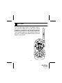
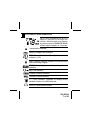
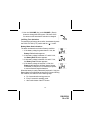
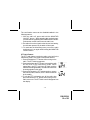
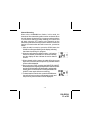
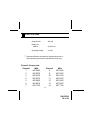
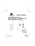
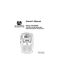
Owners Manual Model FR-1400 Two Way Family Radio Customer Service 1-800-290-6650 Released on 8-18-00. Revision A: Changed pages 13 and 16, 11-3-00. Manufacturer will reduce to 75 per cent. 128-5855A 1 of 20 CONGRATULATIONS ON YOUR SELECTION OF THE FR-1400 (FAMILY RADIO) It is one of the most sophisticated and reliable two way family radios available. BEFORE OPERATING YOUR FR-1400 (FAMILY RADIO) READ THIS MANUAL CAREFULLY 128-5855A 2 of 20 FEATURES Your FR-1400 Family Radio is a portable, easy to use, two-way radio that you can carry almost anywhere. It is skillfully constructed to give you reliable communications for many different applications. The FR-1400 is ideal for use around the house, in your boat, on hunting and camping trips, on the ski slopes or at the mall. -3- 128-5855A 3 of 20 PERFORMANCE Your transceiver will achieve its maximum operating range when communicating with other transceivers in a flat open area with no trees or buildings obstructing its signal. Range may be up to two miles under such conditions. Obstacles such as buildings, trees or mountains will tend to reduce the transceiver’s effective range. FCC WARNING Replacement or substitution of transistors, diodes or other parts of a unique nature, with parts other than those recommended by the manufacturer, may cause a violation of the technical regulations of Part 15 of FCC Rules. SAFETY INFORMATION Your wireless hand-held portable transceiver contains a low power transmitter. When the PTT button is pushed it sends out radio frequency (RF) signals. The device is authorized to operate at a duty factor not to exceed 50%. In August 1996, the Federal Communications Commissions (FCC) adopted RF exposure guidelines with safety levels for hand-held wireless devices. Important: To maintain compliance with the FCC’s RF exposure guidelines hold the transmitter at least 1 inch (2.5 centimeters) from your face and speak in a normal voice, with the antenna pointed up and away. If you wear the handset on your body while using the headset accessory, use only the Audiovox supplied belt clip for this product and ensure that the antenna is at least 1 inch (2.5 centimeters) from your body when transmitting. Use only the supplied antenna. Unauthorized antennas, modifications, or attachments could damage the transmitter and may violate FCC regulations. Normal Position: Hold the transmitter approximately 1” from your face and speak in a normal voice, with the antenna pointed up and away. -4- 128-5855A 4 of 20 FUNCTION AND LOCATION OF THE CONTROLS 4 14 15 16 8 4 2 10 9 3 1 12 13 11 7 6 5 -5- 128-5855A 5 of 20 1. Power Button (POWER ON/OFF): Press and hold this button for 2 seconds to turn the transceiver on or off. 2. PUSH TO TALK (PTT) Button: Press to transmit. Release to receive. 3. MONITOR ON/OFF Button: Press and hold to bypass the squelch and listen to channel activity. 4. Belt Clip: Provides convenient method of carrying the radio. 5. Battery Compartment: Provides installation area for three AA batteries, either Alkaline or rechargeable cells. 6. Speaker: Conveys received voice signals to the listener. 7. MICrophone: Used to pick up voice during transmit mode. 8. VOLUME/CHANNEL Button Up ( the level of the current function. ): Press this button to increase 9. VOLUME/CHANNEL Button Down ( crease the level of the current function. ): Press this button to de- 10. LCD Display: Displays the current FRS channel number as well as other functions. 11. MENU Button : Press this button to select or scroll through all unit functions. 12. SCAN Button: Permits monitoring channels of other transmitting radios. 13. LOCK Button: Permits certain functions to be frozen so that the radio settings cannot be changed accidently. 14. MIC/PHONE Jacks: For use with an external microphone and headset accessory. Please use Audiovox approved accessories only or damage to the radio may result. 15. Antenna: Transmits and receives radio signals. 16. POWER ON Indicator: Indicator flashes green every two seconds when the radio is on. -6- 128-5855A 6 of 20 LCD DISPLAY AND OPERATION The FR-1400 is equipped with an LCD display to indicate its settings and functions. When the radio is on, pressing any button (except for PUSH TO TALK) will back-light the display for 5 seconds. Transmission Indicator Battery Charge Level Indicator FRS Channel Indicator (1–14); Volume level indicator (1-16). Busy Channel Indicator. Appears on display when unit is receiving a signal. SCAN Indicator. Appears on display during channel scanning. Key Lock Indicator Channel Function Indicator Volume Function Indicator PTT Hold Indicator. Appears on display when transmit function is in the hold mode. Shut-Off Timer Mode Indicator -7- 128-5855A 7 of 20 BATTERY INSTALLATION Your FR-1400 requires three “AA” alkaline cells or three rechargeable “AA” cells. Alkaline batteries will provide the best performance from your transceiver. Remove the battery cover by loosening the thumb-screw and rotating the belt clip away from the battery compartment. Release the clip at the bottom of the battery cover; slide the cover down to disengage the tabs from the top of the compartment, and remove the cover from the radio. Observe the polarity symbols inside the battery tray when installing the batteries. CAUTION: Incorrect battery installation can damage the unit. BATTERY SAVER MODE Your FR-1400 has a unique circuit designed to dramatically extend the life of its batteries. This feature initiates radio turn-off after 1, 2 or 3 hours of inactivity (no button selection). The battery saver mode is initiated as follows: 1. Press the MENU button until the hr display appears. Then press the VOLUME (Up) or CHANNEL (Down) button to increase or decrease the elapsed time until automatic turnoff as desired. 2. If no time (0) is selected, the automatic power off feature is disabled. The clock icon will be displayed to indicate that the shutoff timer function is active. 3. The radio will return to the normal operating mode after 10 seconds, or when the PTT button is pressed. If no buttons are pressed during the selected time interval, the radio will sound a unique tone 1 minute prior to turning itself off. -8- 128-5855A 8 of 20 USING YOUR FR-1400 Turning the Transceiver On and Off (POWER ON/OFF) Pressing the POWER ON/OFF button (1) for 1 second will activate the unit. The speaker will sound a beep tone to confirm the transceiver’s activation. In addition, the transceiver will perform a 0.5 -second power-on self-test, whereby the LCD display will show all functional items. To turn the unit off, simply press and hold the power button for 1 second and then release it. While power is applied, the green POWER ON indicator will flash on and off at a 2-second rate. Volume Level Audio reception volume is controlled by the VOLUME/ CHANNEL ( , ) buttons; press ( ) (increase) and/or ( ) (decrease) to adjust the volume to the desired level between 1 and 16 (loudest). Each momentary press of either button will also initiate a single beep whose intensity will increase or decrease in volume accordingly. Call Ring Tone Selection (CA) After the unit is powered on, press the MENU button twice to initiate the Call function. The FR-1400 will transmit a 3-second ringing sound to other transceiver’s tuned to the same channel, thereby signaling other parties that voice communication is desired. To change the call ring tone, proceed as follows: 1. Enter the Call mode as previously explained. The Call (CA) indicator will appear, and the large numeric display will show the current call ring number (between 1 and 5). -9- 128-5855A 9 of 20 2. Use the VOLUME (Up) and CHANNEL (Down) buttons to change the call ring tone. Each one of the five tones can be heard as the selection is changed. Call Ring Tone Activation To transmit the call tone to other radios, simultaneously press the PUSH TO TALK (PTT) switch and the ( ) button. Battery Meter Alert Indications The radio can detect three levels of battery condition: 1. If the battery voltage is greater than 4.2 Vdc, the Battery Full indication appears. 2. If the battery voltage is between 3.7 and 4.2 Vdc, the Battery Half indication appears. 3. If the battery voltage is between 3.4 and 3.7 Vdc, the Battery Low indication appears. 4. If the battery voltage is less than 3.4 Vdc, the Battery Low indication will flash (battery almost exhausted). At this point, it is necessary to replace, or remove and recharge the batteries. When the battery is nearly exhausted (less than 3.4 Vdc), the Battery Meter icon will blink at an interval of 0.5 second. During this condition, the radio will emit a warning beep: a. For 3 seconds after turning power on. b. Every 5 seconds in standby mode. c. After each release of the PTT button. -10- 128-5855A 10 of 20 FUNCTIONS Monitor Button (MONITOR ON/OFF) During the normal operating mode, with the radio powered on and a channel selected, press the MONITOR ON/OFF button for 1 second to turn off the auto-squelch and listen for signals on the current channel. Press the MONITOR ON/OFF button again for 1 second to turn on the auto-squelch function. Function Select (MENU) Button Pressing the MENU button will allow selection of frequency channels, as well as selection of the various unit functions. Each press permits selection of the desired CHANnel (1–14), CAll (1-5), and Auto Power Off (hr) functions. Channel (CHAN) Selection To change the channel, proceed as follows: 1. Press the MENU button until CHAN appears on the display, and current channel display flashes. 2. Press VOLUME (Up) and CHANNEL (Down) buttons to select desired channel (1–14) while channel display continues to flash. 3. The radio will return to the normal operating mode after 10 seconds, or when the PTT button is pressed. Alert/Beep Confirmation Tones Whenever any one of the function select buttons is pressed, except for the PUSH TO TALK (PTT) button, the speaker will sound an alert tone, at a fixed volume level independent of the VOL setting, to confirm each press. When increasing the volume number from 1 to 16, the tone will become progressively louder; when decreasing volume, the tone becomes progressively softer. -11- 128-5855A 11 of 20 The confirmation tones can be disabled/enabled in the following manner: 1. With the radio off, press and hold the MONITOR ON/OFF button. While pressing the monitor button, turn the radio on by pressing the POWER ON/OFF button. Release the monitor button once the radio is on. 2. The radio will receive signals at the volume level setting, but all button presses on the radio will be muted. 3. To reactivate the Alert/Beep tones, turn off the radio and then turn it on again while holding the MONITOR ON/OFF button. PTT Hold Feature The PTT hold feature permits the radio to be held in the transmitting mode. This mode is activated as follows: 1. Press and hold the PTT button while turning on the radio. The PTT hold icon appears. 2. Press and release the PTT button once and the radio will be held in the transmitting mode. While transmitting, the PTT hold icon will flash, and the transmit icon will light steadily. The radio will not receive incoming signals in this mode. 3. Press and release the PTT button again to resume the receive mode; however, the PTT hold icon will still be lit steadily. 4. To exit the PTT hold mode, turn off the radio; then press and hold the PTT button while turning on the radio once more. The PTT hold icon will disappear from the display. -12- 128-5855A 12 of 20 Channel Scanning When active, the SCAN icon flashes. In this mode, the channels of other transmitting radios can be monitored. When the radio detects channel activity, it stops scanning and locks in on the active channel, thereby allowing you to listen and talk back (using the PTT button) to the person(s) on the transmitting end without having to switch channels. If the scan function is not active when the radio is turned on, proceed as follows: 1. After the radio is turned on, press the SCAN button; the SCAN icon will appear flashing on the display, indicating that channel scanning is in progress. 2. When the radio detects channel activity, it will park at the active channel, the SCAN icon will become steady, and the display will also indicate the active channel number. 3. When channel activity ceases, the radio will begin to scan again after 5 seconds, and the previously selected channel number will be displayed. 4. During the scan mode, pressing the MONITOR ON/OFF button will halt scanning temporarily. Both the channel number and the SCAN indication will light steadily, and the radio will stay at the current channel. Pressing the MONITOR ON/OFF button again will resume scanning. 5. To deactivate the scan function, press the SCAN button; the radio will return to the normal operating mode, and the previously selected channel will be displayed. -13- 128-5855A 13 of 20 PTT Time-Out Timer: The PTT Time-Out feature prevents accidental transmission. The radio will emit a warning tone if the PTT button is pressed for 60 continuous seconds and will stop transmission. NOTE: If the PTT hold feature is active, the Time-Out feature will be disabled. Power Save Feature In the normal operating mode, from standby to receive, the power save feature will establish a 50% duty cycle (approximately) for the RF section of the radio to save battery power (300Ms on/300Ms off). If SCAN is activated, the RF receive section will not enter the power save mode, and will continue to scan for channel activity. Key Lock This feature prevents accidental change of unit settings. While enabled, Key Lock allows only the MONITOR ON/OFF, PUSH TO TALK, LOCK and POWER ON/OFF buttons to operate. To enable Key Lock, proceed as follows: 1. Press the LOCK button for at least 2 seconds until the Key Lock icon ( ) appears. 2. To disable the Key Lock function, press the LOCK button for at least 2 seconds until Key Lock icon disappears. -14- 128-5855A 14 of 20 Sending Messages (Transmit): 1. Set the desired channel. 2. Press and hold the PUSH TO TALK (PTT) button while speaking slowly and clearly in a normal voice, approximately 1 inch from the microphone. 3. The transmit indicator will appear steadily while transmitting. 4. Release the PTT button when you finish speaking to receive incoming signals. 5. If the PTT Hold feature is enabled, press and release the PTT button once to put the radio in the transmit mode, which would be the same as holding the PTT button in normal mode. The hold icon appears flashing. Press and release the PTT button again to resume the normal radio receive mode. The hold icon disappears. 6. If the VOLUME (Up) button is pressed while transmitting, the radio will emit the selected call ring tone with the microphone muted. The call ring tone will be heard at the radio speaker at the current volume level. -15- 128-5855A 15 of 20 Receiving Messages (Receive): 1. Set the desired channel for normal operating mode. 2. Adjust the volume control to the desired listening volume by using the VOLUME/CHANNEL ( , ) buttons. 3. The Busy indicator will appear when the radio plays strong received signals through its internal speaker, or through an optional headset. -16- 128-5855A 16 of 20 WARNING n Remove the batteries from the transceiver if it is not expected to be used for long periods. This will eliminate the possibility of battery acid leaking from the batteries and corroding the transceiver. n Avoid exposing the unit to water or extremes of temperature. n Do not use this device in or near a mining facility, which uses remotely triggered explosives or in areas labeled “Blasting Area”. Premature or accidental detonation may result. n Do not attempt to modify or in any way increase the output of this transceiver. Its output is designed to meet the legal limits set by the FCC. n Do not use this device or change its batteries in potentially explosive atmospheres as sparks in such areas could result in an explosion. n Turn your transceiver off wherever posted notices restrict the use of radios or cellular telephones. Facilities such as hospitals may use equipment that is sensitive to RF energy. n Turn your transceiver off on-board aircraft when requested to do so. n Do not place your transceiver in front of a vehicle’s air-bag. If the air-bag deploys, it could propel the transceiver like a projectile. n This transceiver complies with FCC regulations for use in the United States. Use in other countries may be prohibited or restricted by local regulation. Please check with the local regulating agency before using this device outside of the United States. -17- 128-5855A 17 of 20 SPECIFICATIONS* Channels: 14 Output Power: 450 mW Battery Life: Alkaline 30-35 Hours Operating Voltage: 4.5 Vdc * These specifications are subject to change without notice. They represent typical values, individual units may vary. Channel Frequencies: Channel MHz 1 462.5625 2 462.5875 3 462.6125 4 462.6375 5 462.6625 6 462.6875 7 462.7125 Channel 8 9 10 11 12 13 14 MHz 467.5625 467.5875 467.6125 467.6375 467.6625 467.6875 467.7125 -18- 128-5855A 18 of 20 90 DAY LIMITED WARRANTY Applies to Audiovox Family Radio Service Products. AUDIOVOX CORPORATION (the Company) warrants to the original retail purchaser of this product that should this product or any part thereof, under normal use and conditions, be proven defective in material or workmanship within 90 days from the date of original purchase, such defect(s) will be repaired or replaced with new or reconditioned product (at the Company's option) without charge for parts and repair labor. To obtain repair or replacement within the terms of this Warranty, the product is to be delivered with proof of warranty coverage (e.g. dated bill of sale), specification of defect(s), transportation prepaid, to the warranty center at the address shown below. The Company disclaims liability for communications range of this product. This Warranty does not apply to any product or part thereof which, in the opinion of the Company, has suffered or been damaged through alteration, improper installation, mishandling, misuse, neglect, accident, or by removal or defacement of the factory serial number/bar code label(s). THE EXTENT OF THE COMPANY'S LIABILITY UNDER THIS WARRANTY IS LIMITED TO THE REPAIR OR REPLACEMENT PROVIDED ABOVE AND, IN NO EVENT, SHALL THE COMPANY'S LIABILITY EXCEED THE PURCHASE PRICE PAID BY PURCHASER FOR THE PRODUCT. This Warranty is in lieu of all other express warranties or liabilities. ANY IMPLIED WARRANTIES, INCLUDING ANY IMPLIED WARRANTY OF MERCHANTABILITY, SHALL BE LIMITED TO THE DURATION OF THIS WRITTEN WARRANTY. ANY ACTION FOR BREACH OF ANY WARRANTY HEREUNDER INCLUDING ANY IMPLIED WARRANTY OF MERCHANTABILITY MUST BE BROUGHT WITHIN A PERIOD OF 30 MONTHS FROM DATE OF ORIGINAL PURCHASE. IN NO CASE SHALL THE COMPANY BE LIABLE FOR ANY CONSEQUENTIAL OR INCIDENTAL DAMAGES FOR BREACH OF THIS OR ANY OTHER WARRANTY, EXPRESS OR IMPLIED, WHATSOEVER. No person or representative is authorized to assume for the Company any liability other than expressed herein in connection with the sale of this product. AUDIOVOX CORPORATION, 150 MARCUS BLVD., HAUPPAUGE, NEW YORK 11788 1-800-290-6650 128-5329 128-5855A 19 of 20 © 2000 Audiovox Electronics Corp., 150 Marcus Blvd., Hauppauge, NY 11788 128-5855A 128-5855A 20 of 20