1
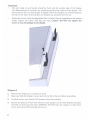
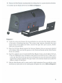
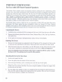
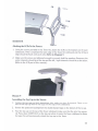
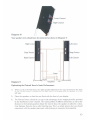
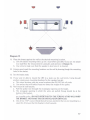
ARTISO
PORTRAIT System
Owner's Manual
.
Thank you for choosing the Artison Portrait Home Theater System. We are pleased that
you have selected our high-performance audio products.
INTRODUGION
The Portrait Home Theater System is the only true 5.1/7.1 Channel solution available on the
market today that is specifically designed for use with flat panel displays and which is fully
compatible with rear projection displays, as well.
The Portrait System is the high performance choice for state-of-the-art DVD, DTS, SACD, and
DVDA multi-channel audio formats. The system faithfully reproduces music and movie sound
tracks without compromise, and does not visually detract from the contemporary appearance
of your flat panel or rear projection display.
To accomplish this, new technologies had to be refined and integrated into the system. The
Portraits provide a lifelike widening of the front sound stage, and eliminate the need for a separate
center channel box above or below the screen. These technologies include the development of
new types of small but powerful woofers and tweeters to provide high-definition, high-impact
surround sound.
The Portrait System is designed to be powered by any high quality AV receiver or
decoder/amplifier combination. The hookup is exactly the same as a typical 5.1 or 7.1 Channel
systems with one important difference - the LCR Front Channels include a unique DualMono
Center Channel speaker in the upper half of each of the LCR's Left and Right speakers. The
Center Channel wire from the receiver is hooked up to one of the two Center Channels and
then it is connected (using the included hookup jumper wire) in parallel with the other Center
Channel. Together, the DualMono Center speakers deliver accurate center channel sound that
appears to come directly from the center of the display screen.
The LCR speakers are designed to attach directly to a flat panel display, whether the display is
placed on a stand or mounted to the wall. Included in each LCR Grille and Bracket Kit are
grilles that match the height and color of the plasma or LCD display and Television Brackets
that allow the speakers to be attached.
Portrait Tower Stands are available that allow placement of the LCR speakers next to the sides
of modern rear projection displays. These stands preserve the acoustic advantages of the
Portrait System without physically altering the display's enclosure. Contact your Artison
Retailer for more information.
The following information will guide you through the installation of your Artison Portrait Home
Theater System. If you need assistance during this process, please contact us during normal
business hours, Pacific Time, at (775) 833-4344.
2
PORTRAIT LCR (Left, Center, Right)
Front Channel Speakers
Mounting the LCR Speakers
1.
Locate and unpack the Television Bracket Hardware, which is in the Portrait PG LCR Grille
Kit, secured within a cardboard shield.
2.
Separate the packing; be very careful not to lose any of the mounting hardware.
3.
Locate the Televison Brackets. These are pieces of heavy gauge steel, which are bent into
a specific shape so that the speakers will mount properly to your particular
display. Typical examples of Television Brackets are pictured below. ote: Brackets do
not all look exactly alike.
Diagram 1
4.
If possible, remove the display from where it is mounted and lay it face down on a soft,
flat surface. This can be a rug or carpeting of sufficient size. or a blanket, towel or other
padding. Be careful not to damage the glass or cosmetic surfaces. This will make the
installation of the television brackets easier. ote: Some installations allow the brackets
to be attached after the television is already installed.
5.
Some display brands require four Television Brackets and some require two. Determine
which Brackets match your specific plasma. Using the supplied screws and washers.
attach the two (or four) Brackets to the rear of the display. Refer to Diagram 2
• Every LCR Speaker System comes with an attached Main Bracket, which is used to
attach the speakers to the Speaker Television Brackets. Additionally the main bracket
may be used to wall mount the system in cases where there is no grill kit available for
a particular model television or because the customer prefers this type of installation.
3
Important
The outer edge of each bracket should be flush with the outside edge of the display.
The ribbed portion of a bracket can extend beyond the side surface of the display - the
exact position will vary from display to display. When the brackets are installed properly,
the ribs on the sides of the brackets are dimpled out and away from the set.
Tighten the screws using the appropriate Allen or Socket Wrench, depending on the plasma
model. Tighten the screws until they are snug. Caution: DO NOT over tighten the
screws or you risk damage to the display.
Diagram 2
6.
Remount the display on its bracket Dr stand.
7.
Make sure that the display is secure and will not fall or tip over before proceeding.
8.
Carefully remove your Portrait LCR speakers from their packing.
9.
Remove the protective foam from between each speaker and its Main Bracket and place
the LCRs on their large, flat sides. WARNING: DO NOT place the speakers on their faces
as this may permanently damage the drivers.
4
10. Remove the Main Bracket mounting knobs by twisting them in a counter-clockwise direction.
11. Carefully slip the Bracket off of the LCR. Refer to Diagram 3
Diagram
3
12. Locate the center point between the top and bottom on each side of the display and place
a short piece of masking tape there. Then using a tape measure, determine the exact
vertical center of the display and make a mark on the tape with a pen or pencil. Doublecheck your measurements.
13. Place the LCR Main Bracket against the Televison Brackets that you previously attached
to the display. Make sure that the grooves on the Televison Bracket and the Main Bracket
fit into one another.
14. Insert the supplied screws to loosely hold the Main Bracket in place, do not tighten them yet
• There are additional screws included in each grill kit to account for loss. It takes only 2
screws per side (One at the top and one at the bottom) to secure the television brackets
and the Main brackets together. The spare holes in the television bracket are to allow for
different models of televisions
15. Slide the Main Bracket until its center mark (a slight indentation) lines up with the center
mark that you made earlier on the masking tape and tighten the screws. Refer to Diagram 4
5
Center Merll
Diagram 4
16. Carefully slide the LCR onto the Main Bracket that is now mounted to the display.
Important
•
•
When you face the display, the right speaker (labeled on the crossover cup on the back of
the LCR) is located on the right side of the display and the left speaker is on the left side.
The Stage Tweeter is located in the rear LOWER portion of the speaker.
When correctly installed, the DualMono center channel speakers should be located
toward the top of the display, with the drivers pointing inward. Refer to Diagram 5
17. Use the knobs that you removed earlier to loosely re-attach the speaker, but do not
tighten the speaker in place yet.
18. Slide the speaker back and forth until the front edge is approximately 1/8" behind the front
surface of the display. Tighten the knobs to hold the speaker in place.
NOTE: It may be easier to perform this step after your speakers have been wired as
described in the next section of this manual.
• •
• •
DualMono
Center Channels
Left
Channel
• •
Diagram 5
6
Right
Channel
• •
Wiring the LCR Left and Right Front Channel Speakers
19. Wire the left and right channels the same as any other speaker. Connect one end of the left
front channel speaker wire to the left front channel terminals of the receiver/amplifier.
Connect the positive wire to the positive terminal on the receiver, and the negative wire to
the negative terminal. Then connect the other end of the left speaker wire, positive and
negative, to the positive and negative terminals located in the cup on the rear of the
speaker. Repeat this proced ure for the right cha nnel speaker wi reo Note: If necessary, strip
the insulation from each of the speaker wires ends approximately 112" and twist the
strands of wire at each of the individual wire ends tightly together. This makes
connecting the wire easier and prevents short circuits to adjacent wires or terminals.
20. Connect the wires to the terminals of the LCRs by pressing on the top of the speaker
terminals; this will open a hole in the side of the terminal. Slip the bare end of the
stripped wire into this hole and release the terminal. The terminal should now securely
hold the wi re in place.
Wiring the LCR Center Channel Speakers
21. Connect one end of the center channel speaker wire, positive and negative, to the positive
and negative center channel terminals of the receiver/amplifier. Connect the other end of the
center channel speaker wire to the center channel input terminal cup on one of the LCR speakers
- you may connect the wire to either of the center channel speakers.
22. Use the supplied jumper wire (red and black wire), or another wire of your choice, to connect
the two center channel speakers in parallel.
• Remove and twist the supplied jumper cable together with the wire that is attached to
the center channel input and re-insert. Be sure that there are no strands of wire that
could short out the positive and negative leads.
• Connect the other end of the wire to the center channel input that has not already been
hooked up to the receiver. Make sure that positive is connected to positive and negative
is connected to negative for all connections.
Your wiring is now complete and should look like the illustration in Diagram 6.
Top
Rear
Right Center
3.1 /5.1 Channel Set Up
Stage Tweeter
Right Channel
Left Center
(-I
1+1 1+1
(-I
(-)
Center
Right
Stage Tweeter
1+1
Left Channel
Left
Amplifier
Diagram 6
Note: '''The portrait system may also be wired in a stereo configuration as in Diagram 6A
7
Top
Rear
Right Center
Stage Tweeter
Left Center
Stage Tweeter
Stereo Set-Up
Right Channel
1+1
+)
•
Right
Amplifier
L
Left Channel
Left
-..J~~~==
Diagram6A
Attaching The Grilles
23. Attach the grilles by aligning the top of the grille with the top of the display and pressing
the grille's pins into the small cups on the front of the speaker. Note: The grilles can fit
tight when the system is new, it may be necessary to hold the speakers from the back
while pressing the grilles into place.
Setting Up The Receiver
24. The DOLBY HIGH PASS SETIING in most receivers is 80Hz when set in the SMALL
SPEAKER position. We have optimized both the LCR Front speakers and the LRS Surround
speakers for this setting. The receiver should be set so that the main speakers operate in
this mode. This will provide the dynamics needed for movies and will allow the system to
be played at high levels with very low distortion.
Adjusting The Settings On The LCR Speakers
There are two switches on each LCR speaker which allow you to adjust the acoustics. One
switch for the Left / Right Channel Stage Tweeter and the other for the Center Channel
Presence Control. Both switches are located on their respective input terminal cups on the
back of each LCR.
Stage Tweeter Settings
Turning on the Stage Tweeter widens the sound stage. The decision to use the Stage Tweeter is
dependant on individual taste and on the particular installation.
25. Adj usti ng the Stage Tweeter
• The switch turns the tweeter on and off. In most installations, the Stage Tweeter should
be left on.
• Since it is difficult to see the markings when the system is mounted, you can tell that
the switch is in the on position by feel. When the switch is set towards the outside of the
system (away from the display) it is in the on position.
8
Presence Control Settings
The Presence Control changes the center channel tweeter level to compensate for differing
room acoustics. This can be adjusted with the three-position switch located in the Center
Channel terminal cup on the back of each LCR speaker.
26. Adjusting the Presence Control
• Normal - the toggle is set towards the outside of the system, away from the display.
Start with the switches in this position first.
• Decreased - the toggle is in the center position. This setting is for acoustically "hard';
highly reflective rooms.
• Increased - the toggle is set towards the display. This setting is for acoustically "soft';
highly absorbent rooms.
Important: Presence Control switches on both speakers should be set to the same positions
for proper balance of the center image.
Nons:
1.
Every LCR Speaker comes with a Main bracket that is used to attach the speakers to the display.
This bracket may also be used to wall mount the system when a Grille Kit is unavailable for
a particular display or because the customer would prefer wall mounting. There are Universal
Grille Kits available in gray, charcoal and black that will fit a 42'; 50:' or 60" display.
2.
Extra screws are included with each kit in case any are lost. It takes 2 screws per side to
secure the Televison Brackets and the Main Brackets together. The spare holes in the
Televison Brackets allow for different models of displays.
9
PORTRAIT TOWER STAND
For Use with LCR Front Channel Speakers
The Portrait Tower speaker system incorporates Artison's advanced sonic engineering, which
provides true, clear audio reproduction and eliminates the need for a separate center channel
speaker box. With the sleek, stylish Tower Kit, the two LCR (Left/Center/Right) speakers are
integrated into attractive floor stands, to be positioned on each side of the television screen.
Each speaker is configured with a patent-pending DualMono Center Channel, in which the
upper portion of both right and left speakers house two matched dedicated speakers to reproduce
the center channel - effectively placing crisp, clear dialogue in the center of the screen, rather
than above or below as with a typical center channel speaker.
The Portrait Tower system is ideal for the new generation of DLp, CRT, and other flat screen
televisions. The Tower option has been designed to allow the Portrait LCR Front Channel
Speakers to be used as a floor standing system. You do not need the grill kits that are required
for Plasma installations because they are included in the Tower Stand Box.
Unpacking the Towers
1.
Carefully remove and place all of the components that were in the Tower box on a soft surface.
2.
Remove the following items from the box: Tower, Pedestal Base, Grille, Top Cap, Hardware,
and Spike Feet.
3.
If any parts are missing or damaged please contact Artison immediately.
Building The Towers
1.
Remove the Main brackets (as explained in the LCR portion of this manual). Set them aside
in case you may need them in the future. These will not be used with the Tower Stand.
2.
With the towers lying on a soft surface, use the M8 screws and the Allen Wrench located
in the tower's hardware kit and attach the bases to the Towers. Refer to Diagram 8
Note: It is helpful to have the bottom of the Towers supported off the surface to allow
the base to fit. The packing may be used for this purpose.
Attaching the feet to the Tower base
1.
Locate and unpack the feet.
2.
Screw the spikes into the bottom of the tower base.
3.
From the top of the foot, screw to locking nuts onto the top of each spike.
4.
Place the rubber socks onto each spike if you are planning on using the speaker on a hard
surface such as a wood or tile floor. If you are using the speaker on carpet we suggest that
you do not use the socks.
5.
You may adjust the speaker so that it is straight by first loosening the spike locking nuts.
Next, turn the spikes to adjust their height and level the speaker. After you have the speaker
in the desired position, re-tighten the locking nut.
10
DIAGRAM 8
Attaching the LCRs To the Towers
1.
Using the screws provided in the Tower Kit, attach the LCRs to the brackets on the tower
sideboards. When completed the back edge of the Tower Kit sideboard and the LCR back
edge should be flush with each other. Refer to Diagram 9
2.
Make sure the screws are tightened enough to securely hold the speakers. Remember, the
center channels should be at the top and the left / right channels should be at the bottom.
(Refer to the LCR part of this manual.)
Diagram 9
Assembling the Top Cap to the Towers
1.
Position the top caps on their appropriate side. make sure they fit properly. There are two
pins on the top cap that fit into cups on the tops of the sideboard.
2.
Remove the protective backing from the double backed tape on the bottom of the top cap.
3.
Place the top cap on the top of the Tower sideboard; make sure that the pins line up properly. Press down CAREFULLY on the top cap where it meets the Tower sideboard to adhere
the tape; this will permanently attach the top cap to the Tower.
11
4.
Carefully line the grill pins up with the grill cups on the LCR. Using even pressure press
the grill into place. DO OT press on the center of the grill surface; apply pressure only at
the corners.
Wiring the lCR left and Right front Channel Speakers
1.
A channel to run your wires is located on the inside of the Tower as well as an area to
attach wire ties for a clean installation. Remember that you must run the parallel wire to
the side where you are connecting the Center Channel.
2.
Hook up the left and right channels the same as any other speaker. Connect one end
of the left front channel speaker wire to the left front channel terminals of the receiver /
amplifier. Connect the positive wire to the positive terminal on the receiver, and the
negative wire to the negative terminal. Then connect the other end of the left speaker wire,
positive and negative, to the positive and negative terminals located in the input terminal
on the back of the speaker. Repeat this procedure for the right channel speaker wire. Note:
If necessary, strip the insulation from each of the speaker wire ends approximately 1/2"
and twist the strands of wire at each of the individual wire ends tightly together. This
makes connecting the wire easier and prevents short circuits to adjacent wires or terminals.
Wiring the lCR Center Channel Speakers
1.
Using wire ties and the supplied wire tie loops, strap the wires to the tower for a clean
appearance. Leave the wire ties loose to allow you to add the center channel wire in the
next step.
2.
Connect one end of the center channel speaker wire, positive and negative, to the positive
and negative center channel terminals of the receiver /amplifier. Connect the other end of
the center channel speaker wire to the center channel input terminals in the cup on one of
the LCR speakers - you may connect the wire to either of the center channel speakers.
3.
Use the supplied jumper wire, or another wire of your choice, to connect the two center
channel speakers in parallel, be sure to route the wire through the wire channel. Your
wiring through the channel should look like Diagram 10 (Right / Center Channel with
wire for amplifier and parallel jumper wire shown)
12
nel
Diagram 10
Your speaker wires should now be connected as shown in Diagram 11
Left Center
Right Center
Stage Tweeter
Stage Tweeter
Right Channel
left Channel
(-)
(
(-)
(-)
(+)
(+)
Center
~t:::=:1:;;:::::::%~
Diagram 11
Righ t'--Amplifier
!::1"--'
~:=:::t~~
Optimizing the Portrait Tower's Sonic Performance
4.
When you face the Television, the right speaker (labeled on the input terminal on the back
of the Portrait Tower) is located on the right side of the display and left speaker is on the
left side.
5.
Place the speakers so that they are flush with the front of your display.
6.
The Portrait Towers should be set up to take advantage of the imaging benefits provided
by the DualMono Center Channel. The varying widths of different televisions as well at the
distance to the listening position dictate the need to focus the speakers to allow for a clean,
clear dialogue that also has a wide listening area. This is a simple process but you should
experiment with the speaker placement while listening to maximize their potential.
13
7.
After you have hooked up your speaker to your receiver or amplifier, remove the grill and
aim the Center Channel (top speaker) at the opposite listening position. This means that
the right center should be pointed towards the left listening area and the left center
should be pointed towards the right listening area. Try slight variations in the angle
of each tower to give you a good center image across the listening plane. Please Refer
To Diagram 12
Diagram 12
Attaching the Grilles
8.
Attach the grilles by aligning the top of the grille with the top of the speaker and press
the grille's pins into the small cups on the front of the speaker. Note: The grille can fit
tight when the system is new so it may be necessary to hold the speakers from the
rear while pressing the grilles into place.
Setting Up The Receiver
9.
14
The DOLBY HIGH PASS SmlNG in most receivers is 80Hz when set in the SMALL
SPEAKER position. The LCR Front speakers and the LRS Surround speakers have been
optimized for this setting. The receiver should be set so that the main speakers operate in
this mode. This will provide the dynamics needed for movies and will allow the system to
be played at high levels with very low distortion.
LRS Surround Satellites
(Left, Right, Surround)
Unpacking the LRS's
1.
Remove the top portion of foam protecting the LRS Surround Speakers.
2.
Carefully lift the Surround out of the packing.
a. When lifting the LRS be careful not to touch the drivers.
3.
Remove them from the protective plastic bag.
4.
Place the speaker on its back. the large flat surface.
5.
When looking at the face of the speakers you will see four screw holes located at the outer
corners, these attach the front of the speakers to the wall mount plate.
6.
Using the supplied Metric #3 Allen Wrench, remove the four screws that hold the wall
mount Bracket to the speaker by turning the screws in a counter-clockwise direction.
7.
Lift the speaker off of the wall mount bracket and set the speaker aside. Refer to Diagram 13
e:>
/
Bracket Screws
\
Diagram 13
Mounting the Speaker Bracket
9.
Determine the best location for mounting the speakers.
a. They should be positioned approximately 70% up the wall. So for ceiling height of 10;'
the speaker should be about 7' from the floor. This is only an approximate dimension;
your room layout will determine the final height the speaker will be mounted.
b. The LRS should be located directly next to, or behind the primary seating area. Try not
to mount them in front of the primary seating location as this is not optimal.
c. Find a location that will not be blocked by objects, such as a plant or mounting the
speaker too close to a corner.
d. Keep the speaker at least two feet away from any corner.
e. When using the Surrounds as rear speakers they should be located approximately the
same distance apart as the front channels and should be at the same height as the
Side Surrounds.
15
10. Determine the proper mounting orientation.
a. The front tweeter and the midrange are wired in phase and should always face the
plasma or projector screen.
b. The port should be on the upper portion of the baffle.
c. Make sure that the speakers are on the correct side of the room; the right speakers are
on your right side when you are facing the television.
d. When the LRS are mounted to the ceiling, the right channels should be located to the
right of the listening position and the in phase tweeters should face the television.
This orientation is correct when the ports face the center of the room towards the
listening position.
e. If you are using the speaker on the ceiling or rear wall, keep the LRS orientation the same
as if it were mounted on the side of the room, then "slide" it to the desired mounting location. Refer To Diagrams 14 & 15
•
,.,.....- Port
•
Diagram 14
16
o
•
•
• -\
Port
Diagram 15
11. Place the bracket against the wall at the desired mounting location.
a. Line the bracket mounting holes up on a stud where possible. Of you can not attach
to a stud follow the instructions for using dry wall anchors in Diagram 14.
b. Use a level to make sure that the speaker is level once it is mounted.
12. Using a pencil, mark the mounting locations on the wall by drawing through the mounting
holes in the bracket.
13. Set the bracket aside.
14. If you were not able to mount the LRS to a stud, use dry wall inserts. Using drywall
anchors create secure mounting locations for the speaker bracket.
a. This should be done with any screw locations that DO NOT hit wall studs.
b. Use anchors that will hold at least two times the weight of the speaker.
15. Now mount the wall bracket.
a. Pull the speaker wire through the rectangular opening on the bracket.
b. The rectangular opening in which the wires are pulled through should be at the
bottom of the bracket.
c. Mount the bracket to the wall using drywall screws and lor the screws for anchors that
you installed earlier. (DO NOT OVER TIGHTEN THE SCREWS AS THIS WILL WARP
THE BRACKET AND MAKETHE LRS INSTALLATION DiffICULT)
d. Use at least 11j4" course thread drywall screws anywhere that you are mounting to a
stud, this will insure that the bracket is held securely.
17
Wiring and Mounting the LRS Speakers
16. Carefully lift the speaker into position.
17. Wire the left and right channels the same as any other surround speaker. Connect the left
positive and negative of one end of the wire to the receiver / amplifier. Connect the left
positive and negative to the speaker terminals located on the rear of the speaker.
18. When connecting the speaker wire to your LRS make sure that the positive and negative
terminals are correctly attached to the positive and negative of the speaker wire.
19. Strip the ends of the speaker wire approximately
Vi'
and twist the wires tightly.
20. Connect the wire to the rear of the LRS by pressing on the speaker terminal; this will open
a hole on the side of the terminal. Slip the end of the stripped wire into this hole and
release the terminal. The terminal should now securely hold the wire in place.
21. While placing the speaker into position be sure that the wires do not get pinched between
the bracket and the speaker.
22. Using the four screws that you removed in step #6 remount the speaker to the
mounting bracket.
a. Insert the screws and tighten by turning in a clockwise direction.
b. Be careful to not over tighten the screws.
Attaching the Grills
23. Remove the grill from the plastic bag.
24. Attach the grills by lining the side of the grill with the one side of the speaker and partially
insert into the grill slot.
25. You can use SLIGHT pressure if necessary to "squeeze" while fitting it into the grill slot on
the opposite side of the speaker. The grills will spring back into shape creating a pressure fit.
Refer to Diagram 16
Diagram 16
Setting up the Receiver
The Dolby High Pass Setting in most receivers is 80Hz when set in the SMALL speaker position.
We have optimized the LRS Surround Channels for this setting. The receiver should be set so
that the main speakers operate in this mode. This will provide the dynamics needed for movies
'
and will allow the system to be played at loud levels with very low distortion.
18
LIMITED WARRANTY
This warranty remains in effect for five years from the date of purchase for speaker products
and one year for electronic products.
This warranty protects the original owner providing that the product has been purchased from
an authorized Artison Dealer in the United States. The original bill of sale must be presented
whenever warranty service is required. for warranty service outside the United States, contact
the authorized Artison Acoustics distributor in the country where the product was purchased.
Except as specified below, this warranty covers all defects in material and workmanship. The
following are not covered: Damage caused by accident, misuse, abuse, product modification or
neglect, damage occurring during shipment, damage from failure to follow instructions contained
in the Owners Manual, damage resulting from the performance of repairs by someone not
authorized by Artison, or any claims based on misrepresentations by the seller. This warranty
does not cover incidental or consequential damages. It does not cover the cost of removing or
reinstalling the unit. This warranty is void if the serial number has been removed or defaced.
You are responsible for transporting your product for repair. However, Artison will pay return
freight charges if the repair is covered under warranty.
This warranty gives you specific legal rights. You may also have other rights which vary from state
to state. Some states do not allow the exclusion or limitation of incidental or consequential
damages or limitations on how long an implied warranty lasts, so the above may not apply to you.
Please make note of the following information and retain for your record.
Product Name
Model Number
Store Name
Purchase Price
_
_
HOW TO OBTAIN SERVICE
Please call us at (775) 833-4344, or write to: ARTISO (Attention: Customer Service
Department), 774 Mays Blvd., Suite 10-183, Incline Village, V 89451.
We will promptly advise you of what action to take. We may direct you to an authorized
Artison Service Center or ask you to send your speaker to the factory for repair. You will
need to present the original bill of sale to establish the date of purchase. PLEASE DO OT
SHIP YOUR ARTISON PRODUCT TO THE fACTORY fOR REPAIR WITHOUT PRIOR
AUTHORIZATION. PLEASE DO OT RETUR PRODUCT TO THE ABOVE ADDRESS,
IT IS OT A SERVICE LOCATIO . You are responsible for transporting your product for
repair and for payment of any initial shipping charges. However, we will pay the return
shipping charges if the repairs are covered under warranty.
19
Artison. LLC
774 Mays Blvd., Suite 10-183
Incline Village, NE 89451 USA
Phone 775 833-4344
Fax
775 833-0223
Email [email protected]
www.artisonusa.com
Web
02005 Artison. Uc. All righlS reserved.
Place
Stamp
Here
ARTISON
Attention: Customer Service Department
774 Mays Blvd., Suite 10-183
Incline Village, NV 89451
Name
Address
Company
Telephone Number
Email
Date/Price
Name of Dealer
Address of Dealer
Product(sl
Model Numbers
Please rate your overall experience with the dealer 0 Excellent
2 Where did you first learn about ARTISaN? 0 Magazine
0 Good
0 Newspaper
0 Average
0 Friend
3. What other brand of speakers/subwoofers did you consider? 0 Polk
0 Bose
o Paradigm 0 Niles 0 KEF 0 Definitive Technologies 0 Other
Serial Numbers
0 Poor
0 Salesperson
0 Sonance
0 Brochure 0 Other
0 Infinity
0 JBL
_
0 Boston Acoustics
_
0 Mirage
4 Please check the most important factors influencing this purchase?
o Duality of sound 0 Magazine Review 0 Recommendation of salesperson 0 Appearance 0 Technical Specifications 0 Ease of operation
o Recommendation of friend/family . 0 Value for price 0 ARTISaN's reputation 0 Previous owner of ARTISaN's products
o Other
_
5. What is the primary use for this purchase? 0 Music playback
0 Front main speakers
o Rear (surround sounorspeakers 0 Replacing speakers 0 Add to existing system
0 First speaker purchase
0 Other
6 Which of these specialty magazines do you read? 0 Sound & Vision 0 Audio Video Interiors 0 Stereophile
o Absolute Sound 0 Architectual Digest 0 Consumer Reports 0 Home Theater 0 Other
7 0 Male
0 Female
8 Age Group?
9 Family income? 0 Under $15.000
0 Under 18
0 $15.000 - 24,999
10 Education (please Check which category appliesl
0 18-24
0 25-34
0 35-44
0 $25,000 - $49,000
0 High School
0 45-54
0 $50,000 - $74,999
0 Some College
0 Movie/Home Theater
_
0 Stereophile Guide to Home Theater
.
_
0 55-64
0 Over 64
0 $75,000 - $100,000
0 Completed College
0 Over $100,000
0 Graduate School
11 What is your occupation? 0 Self employed/Owner
0 Student
0 Professional Technical
0 Homemaker
0 Upper Management
o Retired 0 Middle Management 0 Sales/Marketing 0 Clerical/Service Worker 0 Laborer/Tradesman
12 Do you have any comments about your new ARTISaN products?
_
o Yes, I would like to receive ARTISaN mailings when they become available
0 No, Please do not send me ARTISaN mailings
------_._--------------------------------------------- ----
-------------
WE WOULD LIKE TO THANK YOU FOR CHOOSING ARTISON
At Artison. we are dedicated to the art and technology of sound, providing you with high quality products that bring you closer than ever to the live
performance In order to maintain our high standards, we would like to better understand your needs, please fill out this questionnaire card and return it to
us within TEN days
LIMITED WARRANTY
This warranty remains in effect for five years from the date of purchase for speaker products and one year for electronic products
THIS WARRANTY PROTECTS THE ORIGINAL OWNER PROVIDING THAT THE PRODUCT HAS BEEN PURCHASED FROM AN AUTHORIZED ARTISON DEALER IN THE
UNITED STATES THE ORIGINAL BILL OF SALE MUST BE PRESENTED WHENEVER WARRANTY SERVICE IS REQUIRED. FOR WARRANTY SERVICE OUTSIDE THE
UNITED STATES, CONTACT THE AUTHORIZED ARTISON DISTRIBUTOR IN THE COUNTRY WHERE THE PRODUCT WAS PURCHASED
Except as specified below, this warranty covers all defects in material and workmanship The following are not covered Damage caused by accident,
misuse, abuse, product modification or neglect. damage occurring during shipment. damage from failure to follow instructions contained in the owners
manual, damage resulting from the performance of repairs by someone not authorized by Artison, or any claims based on misrepresentations by the seller
ThiS warranty does not cover incidental or consequential damages It does not cover the cost of removing or reinstalling the unit. This warranty is void if
the serial number has been removed or defaced.
You are responsible for transporting your product for repair However, Artison wilL pay return freight charges if the repair is covered under warranty.
This warranty gives you specific legal rights. You may also have other rights which vary from state to state Some states do not allow the exclusion or
limitation of incidental or consequential damages or limitations on how long an implied warranty lasts, so the above may not apply to you.
Please make note of the following information and retain for your record.
Product Name
Store Name
Model/Serial Number
_
Purchase Price
_
_
HOW TO OBTAIN SERVICE
Please call us at (775) 586-9574, or write to ARTISON (Attention: Customer Service Department), 774 Mays Blvd, Suite 10-183, Incline Village, NV 89451.
We will promptly advise you of what action to take. We may direct you to an authorized Artison Service Center or ask you to send your speaker to the
factory for repair You will need to present the original bill of sale to establish the date of purchase PLEASE DO NOT SHIP YOUR ARTISaN PRODUCT FOR
REPAI~ WITHOUT PRIOR AUTHORIZATION. PLEASE DO NOT RETURN PRODUCT TO THE ABOVE ADDRESS, IT IS NOT A SERVICE LOCATION. You are responsible
for transporting your product for repair and for payment of any initial shipping charges. However. we will pay the return shipping charges if the repairs are
covered under warranty.