1
SERVICE MANUAL
CRT DISPLAY
Diamond PLUS 230SB / Diamond PLUS 230SB -BK
(C22BW701)
NEC-MITSUBISHI ELECTRIC VISUAL SYSTEMS CORPORATION
SEPTEMBER 2002
CBB-S5783
X-RADIATION WARNING
The surface of pucture tube may generate X-Radiation.
Precaution during servicing, and if possible use of a lead apron or metal
for shielding is recommended. To avoid possible exposure to X-Radiation
and electrical shock hazard, the high voltage compartment and the picture
tube shield must be kept in place whenever the chassis is in operation.
When replacing picture tube use only designated replacement part since
it is a critical component with regard to X-Radiation as noted above.
CRITICAL COMPONENT WARNING
• In the schematic diagram/parts list, the components marked "
" are
critical components for X-ray radiation.
When replacing these parts, use exactly the same one indication in
parts list.
• If one or some of the components listed below are replaced, the high
voltage and the operating voltage of high voltage hold-down circuit must
be re-adjusted according to Clause 2.4 ADJUSTMENT on page 2-6 :
T701, IC102, IC104, R706, R707
ii
Contents
1. Circuit description ......................................................................................................................... 1-1
1.1 Power block ......................................................................................................................... 1-1
1.1.1 Outline ...................................................................................................................... 1-1
1.1.2 Rectifying circuit and higher harmonics suppression (active filter) circuit ...... 1-1
1.1.3 Sub power circuit ...................................................................................................... 1-2
1.1.4 Main power circuit ..................................................................................................... 1-2
1.1.5 Demagnetizing circuit ............................................................................................... 1-2
1.1.6 Power management circuit ...................................................................................... 1-2
1.2 Deflection processor block ................................................................................................ 1-3
1.2.1 Deflection processor (IC601) .................................................................................. 1-3
1.2.2 Pressure-reduction type horizontal deflection power circuit (IC5C0) ............... 1-3
1.2.3 Horizontal width control circuit ............................................................................... 1-3
1.2.4 Vertical deflection circuit ......................................................................................... 1-3
1.2.4.1 Sawtooth waveform generation, vertical size/position control, and
linearity control circuit ............................................................................... 1-3
1.2.4.2 Vertical output amplification circuit ......................................................... 1-4
1.2.5 High voltage block .................................................................................................... 1-4
1.2.6 DBF (Dynamic Beam Focus) circuit ....................................................................... 1-5
1.3 Video block .......................................................................................................................... 1-6
1.3.1 Video signal amplifier circuit ................................................................................... 1-6
1.3.1.1 Video clamp ................................................................................................. 1-6
1.3.1.2 Video blanking ............................................................................................ 1-6
1.3.1.3 Video mixing/amplifying ............................................................................. 1-6
1.3.1.4 Control of contrast and white balance .................................................... 1-6
1.3.2 Cut-off control circuit ................................................................................................ 1-7
1.3.2.1 Control of brightness .................................................................................. 1-7
1.3.2.2 Control of BIAS ........................................................................................... 1-7
1.3.3 OSM (On Screen Manager) ..................................................................................... 1-7
1.3.4 Asset circuit ............................................................................................................... 1-8
1.3.5 AUTO-SIZE function ................................................................................................. 1-8
1.3.6 SB MODE (Super Bright Mode) function ............................................................... 1-8
1.3.6.1 Adjustment item/operating function in selecting SB Mode .................. 1-8
1.3.6.2 Circuit (cathode) operation in selecting SB Mode [Window pattern] .. 1-9
1.3.6.3 SB Mode setting data and control method ............................................. 1-9
1.3.7 CONSTANT BRIGHTNESS function ...................................................................... 1-9
1.4 CRT compensation block ................................................................................................... 1-10
1.4.1 Rotation circuit .......................................................................................................... 1-10
1.4.2 Corner purity circuit .................................................................................................. 1-10
1.4.2.1 Corner purity circuit operation .................................................................. 1-11
iii
1.4.3 Digital dynamic convergence clear (DDCC) circuit ............................................. 1-11
1.4.3.1 Production of compensation current waveform ..................................... 1-11
1.4.3.2 Waveform, and operation on the picture ................................................ 1-12
1.4.3.3 Adjustment method .................................................................................... 1-12
1.4.3.4 Block diagram ............................................................................................. 1-12
1.5 Control block ........................................................................................................................ 1-17
1.5.1 Function of control circuit ........................................................................................ 1-17
1.5.2 Auto-tracking process .............................................................................................. 1-17
1.5.3 EEPROM .................................................................................................................... 1-17
1.5.4 On-Screen-Manager (OSM) controller .................................................................. 1-17
1.5.5 Heater voltage control .............................................................................................. 1-17
1.5.6 Protection circuit operation ..................................................................................... 1-17
1.5.6.1 X-ray protector ............................................................................................ 1-17
1.5.6.2 High voltage data error detection ............................................................ 1-18
1.5.6.3 Beam current protector .............................................................................. 1-18
1.5.6.4 Power-On Indicator (LED) flickering pattern in each protector operating .... 1-18
1.5.6.5 Operating time ............................................................................................ 1-18
1.5.6.6 The DDC communication ........................................................................... 1-18
1.5.6.7 Microcomputer pin assignment ................................................................ 1-19
1.6 Safety protection circuit and X-ray protection circuit .................................................... 1-20
1.6.1 X-ray protection circuit ............................................................................................. 1-20
1.6.2 Beam current protection circuit .............................................................................. 1-20
1.6.3 IC701 overcurrent protection circuit ...................................................................... 1-20
1.6.4 IC701 overload protection circuit ........................................................................... 1-20
1.6.5 IC902 overcurrent protection circuit ...................................................................... 1-20
1.6.6 Short-circuit protection circuit on secondary power side ................................... 1-20
1.6.7 Overvoltage protection circuit ................................................................................. 1-20
1.7 Adjustment ........................................................................................................................... 1-21
1.7.1 Adjustment mode ...................................................................................................... 1-21
1.7.2 User mode (Normal mode) ...................................................................................... 1-21
1.7.3 Factory mode ............................................................................................................. 1-24
1.7.3.1 How to entering to Factory mode ............................................................. 1-24
1.7.3.2 How to cancel Factory mode .................................................................... 1-24
1.7.3.3 How to enter FACTORY-HV mode ........................................................... 1-24
2.
Adjustment procedure ............................................................................................................... 2-1
2.1 Measuring instruments ....................................................................................................... 2-1
2.2 Preparatory inspections ..................................................................................................... 2-1
2.3 Names of each monitor part .............................................................................................. 2-2
2.3.1 Configuration of front control panel ....................................................................... 2-2
2.3.2 Configuration of rear input connector (signal input) ........................................... 2-2
iv
2.3.3 OSM display matrix .................................................................................................. 2-3
2.3.3.1 User mode ................................................................................................... 2-3
2.3.3.2 Factory mode .............................................................................................. 2-4
2.4 Adjustment ........................................................................................................................... 2-7
2.4.1 How to select the factory adjustment (FACTORY) mode ................................... 2-7
2.4.1.1 Selecting with front panel switches ......................................................... 2-7
2.4.2 Adjustments before aging ........................................................................................ 2-7
2.4.2.1 Adjusting the high voltage and high voltage protector ......................... 2-7
2.4.2.2 FOCUS adjustment (Rough adjustment) ................................................ 2-8
2.4.2.3 Shock test .................................................................................................... 2-8
2.4.2.4 Preadjustment before aging ...................................................................... 2-8
2.4.2.5 Adjusting the landing (ITC/4 corner purity adjustment) ........................ 2-9
2.4.3 Adjusting the picture size, position and distortion, DBF amplitude and phase 2-9
2.4.3.1 Adjusting the picture inclination ............................................................... 2-9
2.4.3.2 Adjusting the back raster position ........................................................... 2-9
2.4.3.3 Adjusting the left/right distortion, picture width, picture position (LEFT/
RIGHT) and vertical linearity (all preset) ................................................ 2-10
2.4.3.4 Adjusting the DBF amplitude and phase ................................................ 2-10
2.4.4 Adjusting the cut off ................................................................................................. 2-11
2.4.4.1 Adjusting BTCEN (BRIGHT-CENT), BTMAX (BRIGHT-MAX) and BS1
(BIAS-H) ....................................................................................................... 2-11
2.4.4.2 Adjusting BS2 (BIAS-M) / BS3 (BIAS-L) .................................................. 2-12
2.4.5 Setting CONSTANT BRIGHTNESS circuit (Factory mode) ................................ 2-13
2.4.5.1 Reading beam current default data ......................................................... 2-13
2.4.5.2 Confirming CONSTANT BRIGHTNESS function ................................... 2-13
2.4.6 Adjusting the RGB drive signal ............................................................................... 2-13
2.4.6.1 Adjusting GN1 (GAIN-H) (adjustment of 9300K) .................................. 2-13
2.4.6.2 Adjusting ABL .............................................................................................. 2-15
2.4.7 Adjusting the focus ................................................................................................... 2-15
2.4.8 Adjusting the convergence ...................................................................................... 2-16
2.4.8.1 Adjusting with ITC ...................................................................................... 2-16
2.4.8.2 Adjusting DDCP .......................................................................................... 2-18
2.4.9 Default settings (With factory mode) ..................................................................... 2-23
2.5 Inspections (In normal mode) ........................................................................................... 2-24
2.5.1 Electrical performance ............................................................................................. 2-24
2.5.1.1 Withstand voltage ....................................................................................... 2-24
2.5.1.2 Grounding conductivity check .................................................................. 2-24
2.5.1.3 Degaussing coil operation ......................................................................... 2-24
2.5.1.4 IPM OFF MODE function operation (Set the AC power input to 230V) ....... 2-24
2.5.1.5 Confirming the GLOBAL SYNC (CORNER-Purity) function ................. 2-25
2.5.1.6 Focus, picture performance ...................................................................... 2-25
v
2.5.1.7 Misconvergence .......................................................................................... 2-25
2.5.1.8 Picture distortion ........................................................................................ 2-26
2.5.1.9 Linearity ....................................................................................................... 2-28
2.5.1.10 Adjustment value list ................................................................................ 2-29
2.5.1.11 Checking the functions during Composite Sync input ........................ 2-30
2.5.1.12 Confirming the reset operation ............................................................... 2-30
2.5.1.13 Confirming the full white luminance/color coordination ...................... 2-30
2.5.1.14 Confirming CONVERGENCE compensation function ......................... 2-30
2.5.1.15 Confirming ROTATION compensation function ................................... 2-30
2.5.1.16 Luminance/color coordination uniformity .............................................. 2-30
2.5.1.17 Confirming the color tracking ................................................................. 2-31
2.5.1.18 CRT installation position ........................................................................ 2-31
2.5.1.19 Confirming SB MODE operation ............................................................ 2-31
2.5.1.20 Confirming AUTO-ADJUST operation ................................................... 2-32
2.5.1.21 Others ......................................................................................................... 2-32
2.6 DDC function, check of asset management .................................................................... 2-33
2.6.1 DDC write data contents .......................................................................................... 2-34
2.6.2 Self-diagnosis shipment setting ............................................................................. 2-35
2.7 Default inspection ............................................................................................................... 2-35
2.7.1 Default setting of switches ...................................................................................... 2-35
2.7.2 Default setting of OSM ............................................................................................. 2-35
2.7.3 Checking the labels .................................................................................................. 2-35
2.7.4 Packaging .................................................................................................................. 2-35
2.8 Degaussing with handy-demagnetizer ............................................................................. 2-36
2.8.1 General precautions ................................................................................................. 2-36
2.8.2 How to hold and use the handy-demagnetizer ................................................... 2-36
2.9 Caution ................................................................................................................................. 2-36
2.10 Timing chart ....................................................................................................................... 2-37
2.11 Adjustment timing ............................................................................................................. 2-38
3.
Trouble shooting
4.
Wave form
5.
Schematic diagram
6.
Removal Instruction Sheet of Bezel and Back cover
7.
Exploded view/Packing view
<Appendix>
Serial number information
Specification
User's guide
All parts list
vi
1. Circuit description
1. 1 Power block
1.1.1 Outline
The power block is compatible with the business electric power, 100 to 120VAC/220 to 240VAC (50/60Hz).
The active filter circuit is adopted to suppress the higher harmonic current.
The circuit block is composed of two switching regulators, the main power which is the configuration used
the flyback converter system of pseudo resonance operation and the sub power which is the configuration
used PWM (pulse wise modulation) system.
The output on the secondary side is shown in Table 1.
Power block
Main power side
Sub power side
Output voltage
+215V
+80V
+15V
-15V
+12V
+8V
+5V
P-OFF+5V
Mai load
H. deflection circuit, Cu-off circuit
Video circuit, DBF circuit, High voltage circuit
H. deflection circuit, Rotation circuit
Convergence circuit, Corner purity circuit
Video circuit, H. deflection circuit
Heater
Microcomputer (MPU)
VIDEO circuit
Table 1
1.1.2 Rectifying circuit and higher harmonics suppression (active filter) circuit
The AC input voltage is rectified in the full wave mode with the diode bridge in D901 and input to pin 5 of
L903. The voltage of both end of C911 is the DC voltage approx. 390VDC boosted with the booster
circuit (active filter circuit) composed of IC901, Q901, L903 and D902. The active filter circuit compares
the voltage input to pin 1, pin 3 and pin 4 of IC901 and controls Q901 ON/OFF period so that the current
flows to L903 be sine-waved. The AC input current is sine-waved in the same phase with the input
voltage so as to improve the power factor, and the harmonic current is controlled consequently.
AC
To Main power
and sub power
D933
L902
D901
⑥ ⑤④③ ②①
R904
C906
D902
L903
R913
R905
AC
⑦ ⑧ ⑨⑩ ⑪ ⑫
R906
R914
L905
R911
R907
R915
⑤
⑦
③
Q901
R912
R917
R909
R908
①
IC901
From Sub power
R937
C910
⑧
Vcc
C907
④
⑥
②
C908
Fig. 1
1- 1
R910
+
C911
1.1.3 Sub power circuit
When the power switch is turned ON, the rectified and smoothed DC voltage (AC voltage x √2) is
supplied to pin 5 of IC903, and is charged to C930 through pin 1. When pin 1 reaches 5.7V, oscillation is
started in IC903, and the built-in output FET is put into operation to add the pulse voltage between pin 5
and pin 3 on the primary side of T902. The flyback voltage in proportion to the voltage on the primary
side is generated on the secondary side, then the DC voltage is generated with the half-wave rectifier
circuit composed of D971 and C971. The DC voltage generated at the secondary side is monitored by
IC922 through R976, R977 and R978. This information detected at IC922 is fed back to pin 1 of IC903
via PC902, and the ON period of output FET internal IC903 is controlled to keep the DC voltage on the
secondary side constantly. The flyback voltage in proportion to the voltage on the primary side is also
generated at pin 2 of T902. The pulse voltage generated at pin 2 of T902 is converted to the DC voltage
at D932 and C931, and supplied to pin 8 of IC901 and pin 4 of IC902 via Q902.
1.1.4 Main power circuit
When the P-SUS signal from microcomputer is turned to HI, Q902 is turned to ON, and the voltage approx.
+18V is supplied to pin 4 (Vcc terminal) of IC902 from pin 2 of T902.
When the voltage of pin 4 of IC902 reaches approx. +16V, oscillation is started in the circuit, and the
built-in output FET is put into operation to add the pulse voltage between pin 5 and pin 2 on the primary
side of T901. The flyback voltage generated at the secondary side in proportion to the one in the primary
side is rectified at D961, D963, D964, D965 and D967 and smoothed at C961, C963, C964, C965 and
C969 to generate the DC voltage. The DC voltage generated at the secondary side is monitored by
IC921 through R960, R961, R962 and R985. The information detected at IC921 is fed back to pin 1 of
IC902 via PC901, and the ON period of output FET internal IC902 is controlled to keep the DC voltage on
the secondary side constantly.
1.1.5 Demagnetizing circuit
When the power is turned ON or the manual demagnetizing function on OSM menu is set to ON, pin 47 of
IC102 on the main board is turned to HI, and Q950 and RL901 are also turned ON.
When RL901 is turned ON, the current flows to the demagnetizing coil, however, the demagnetizing
current gradually converges with the fever of TH902.
1.1.6 Power management circuit
This monitor carries the power management function. This function is effective only when being
connected with the personal computer carrying the power management function.
Mode
NORMAL
SUSPENSION
H-SYNC
ON
OFF
ON
OFF
V-SYNC
ON
ON
OFF
OFF
State
Displaying a picture
No picture
CRT heater is
decreased voltage
mode (approx. 1.5V)
Display
Displaying a picture
No raster
The power consumption and the indication of Power-On Indicator for each mode are as follows.
Mode
NORMAL
SUSPEND
Power consumption
125W
2W or less
Power-On Indicator
Green
Orange
The control signal executes the power management function is output from microcomputer IC102. The
control signal is composed of two signals, SUSPEND and P-OFF. The operating state of each signal is
as follows.
Control signal name Pin of IC102
Normal
Suspension
SUSPEND
Pin 5
H
L
P-OFF
Pin 42
H
L
1- 2
1.2 Deflection processor block
1.2.1 Deflection processor (IC601)
Deflection processor IC601 horizontally compensates wise, position and distortion, and vertically controls
heights, position and linearity.
IC601 automatically tracks the frequency to output the appropriate horizontal/vertical drive pulse.
IC601 also outputs the horizontal parabola waveform for focus and the waveform for convergence
compensation.
1.2.2 Pressure-reduction type horizontal deflection power circuit (IC5C0)
IC5C0 compares the parabola waveform output from pin 64 of IC601 (this waveform controls the
horizontal width and distortion) with the sawtooth waveform (this waveform is synchronized with the
horizontal frequency) in order to output the +B drive pulse. The +B drive pulse output from pin 9 of IC5C0
will accumulate the 215V energy in T550 during Q5F1 ON period. During Q5F1 OFF period, the
accumulated energy will be released, and integrated by T550 and the S-shaped compensation capacitor.
The duty of this drive pulse depends on the DC level of the parabola waveform that is output from IC601.
1.2.3 Horizontal width control circuit
Q550 is controlled by the horizontal drive pulse that is output from IC601. When Q550 is ON, the energy
will be accumulated in the horizontal deflection yoke. When Q550 is OFF, the energy will flow into C550.
While repeating this operation, horizontal deflection will be carried out.
The collector pulse of Q550 will be subject to voltage division by C590 and C591, and the voltage-divided
pulse will be used for switching synchronization of the high-voltage control IC701 and also used as the
AFC pulse.
The duty of the +B drive pulse output from pin 9 of IC5C0 will be subject to change in order to control the
horizontal width. The parabola waveform output from IC601 is compared with the feedback waveform
output from T5C0 to obtain the comparison waveform, and this comparison waveform threshes the
sawtooth waveform inside IC5C0 in order to control the duty. If the duty is changed, the rectified voltage of
the S-shaped compensation capacitor will be changed, and the horizontal width will be also changed. The
vertical parabola waveform is generated inside IC601, and then mixed with the DC level for horizontal
width control. After that, the mixed parabola waveform will be output from 64 pin of IC601, and added to
IC5C0. This parabola output will be used for compensation of pin-cushion distortion, barrel distortion,
trapezoidal distortion, and upper/lower distortion.
1.2.4 Vertical deflection circuit
1.2.4.1 Sawtooth waveform generation, vertical size/position control, and linearity control circuit
If the vertical synchronization signal is input to 42 pin of IC601, the bipolar sawtooth waveform having the
same frequency as the input will be output from pins 1 and 11 of IC601. IC601 receives compensation
data from the MPU (IC102) to compensate the vertical size, vertical position, vertical raster position,
vertical linearity, and vertical linearity balance, and then outputs the compensated sawtooth waveforms
from pins 1 and 11. Pin 2 outputs the voltage to show the vertical deflection intermediate point.
The OP amplifier at the next stage outputs a signal to show the difference of the bipolar sawtooth
waveform. For this output, the RC low pass filter is adopted to eliminate the digital gradation of the output
waveform. In addition, pins 62 and 63 of IC601 will be turned ON during retracing operation in order to
prevent deterioration of the linearity and dispersion of scanning lines. Moreover, Q603 and Q604 are
switched depending on the vertical frequency in order to improve the linearity.
1- 3
IC601
VSAW-P
R652
11
R658
2
R650
VSAW-N
1
1
3
IC603
5
7
6
R642
IC603
R651
IMID
R648+R649
R645+R646
R647
C628
2
R637
Q604
SW-VLIN1
Q603
SW-VLIN2
63
62
Fig. 2
Vertical sawtooth waveform output circuit
1.2.4.2 Vertical output amplification circuit
A current proportional to the waveform of the voltage input to IC401 will flow to the vertical deflection coil
(V-DY). R410 reads out the voltage waveform of the vertical deflection current, and then feeds back it to
IC401.
R419+R409
IMID
R411
4
V SAW Input
V-DY
IC451
5
2
+
R405
R410
Pump Up
R406+R418
1
6
3
7
VFLY
C404
-15.0V
D401
+15.0V
Fig. 3
Vertical output amplifier circuit
1.2.5 High voltage block
The high voltage block applies PWM control system that controls ON/OFF time of the high voltage
generation FET.
IC701 is the control IC that executes PWM control. The pulse voltage generated at Q701 is boosted at
T701 (FBT) to generate 27kV. To keep the high voltage stably, the feedback voltage from pin 10 of T701
is adopted, the control voltage from pin 56 of microcomputer IC102 is returned to pin 5 of IC701 and the
pulse wise of PWM output is controlled. PWM synchronizes with the horizontal frequency. Trigger pulse
for synchronizing is output from the divided collector pulse of the horizontal deflection output TR Q550,
and is input to pin 8 of IC701.
For adjustment of high voltage value, the voltage of pin 56 of IC102 is adjusted with the adjustment item
HV-ADJ-CAUTION on the OSM menu.
1- 4
1.2.6 DBF (Dynamic Beam Focus) circuit
The horizontal/vertical DBF voltage is respectively generated and amplified, then synthesized at T7A1.
As for the horizontal DBF voltage waveform, the parabola waveform voltage (approx. 0.5Vp-p) is output
with IC601, and amplified about 10 times with OP-AMP IC6A2. After that, it is amplified to 50-60Vp-p
with Q7B5 (the amplification factor is about 10 times), then it is amplified about 10 times with T7A1.
On the other hand, as for the vertical DBF voltage waveform, the parabola waveform voltage (approx.
1.0Vp-p) is output from IC601. It is amplified about 40 times at Q7A1, and the vertical parabola wave is
superposed to the horizontal parabola wave on the secondary side of T7A1, then consequently
synthesized. The collector pulse voltage of the high voltage output TR (Q701) rectified at D7A1 and
C7A1 is used for the power source of Q7A1. The synthesized DBF waveform is input to pin 12 of T701.
1- 5
1.3 Video block
1.3.1 Video signal amplifier circuit
MPU
IC102
D-SUB
CN216
13
44
43
35
10
16
17
13
14
SDA SCL
CLP-IN
B
1
R
IC 211
Pre - Amp
1
G
8
27
R
9
25
B
11
9
DAC
DAC
DAC
R-Bias B-Bias G-Bias
19
20
21
10
15
IC 210
MAIN
Amp
29
11
3
IC 601
IC 215
6
G
2
3
Retrace
BLK in
40
B OSD
G OSD
R OSD
8
17
19
5
G
3
R
1
B
IC212
OSD
18
16
11
OSD BLK
DET
BIAS circuit
Fig. 4
Video signal amplifier circuit
1.3.1.1 Video clamp
The clamp signal (positive polarity, 3.3 Vo-p) output from pin 35 of the MPU (IC102) is input to pin 13 of
IC211. The clamp signal is normally set to the back of the video signal (clamp position of OSM menu:
BACK). To correspond to the Sync on Green signal, the clamp signal can be set to the front of the video
signal (clamp position of OSM menu: FRONT). If the signal is a separate signal, changing the clamp
position of the OSM menu to FRONT or BACK will not change anything.
1.3.1.2 Video blanking
The horizontal/vertical retrace line (blanking) signal (positive polarity, 3.3 Vo-p) output from pin 40 of IC601
is input to pin 13 of IC215. IC215 reverses the polarity and amplifies the waveform (positive polarity,
3.3Vo-p -> negative polarity, 5.0Vo-p), and then reverses the polarity again (negative polarity, 5.0Vo-p ->
positive polarity, 5.0Vo-p) to output the blanking signal. This blanking signal is input to pin 14 of IC211 to
perform blanking operation during horizontal/vertical retracing operation.
To perform image blanking at switching the signal mode or at turning ON or OFF the power, the contrast
and the brightness will be set to MINIMUM.
1.3.1.3 Video mixing/amplifying
IC211 mixes the video signal with the OSM signal (G, R, and B signals of pins 9, 10, and 11) and with the
video blanking signal described in Sec. 1.3.1.2. I2C bus (pins 16 and 17 of SCL and SDA) fixes the black
level of the mixed video signal to 1.8V, and amplifies the mixed video signal (0.7Vp-p -> approx. 2.6Vp-p).
After that, the B, R, and G signals are output from pins 25, 27, and 29, respectively. The video signal
output from IC211 is input to IC210, where the signal is amplified (approx. 2.6Vp-p -> approx. 36Vp-p),
and the black level is fixed to 67V. After that, the B, R, and G signals are respectively output from pins 1, 3,
and 5.
1.3.1.4 Control of contrast and white balance
The MPU (IC102) sends the 8-bit contrast/white balance control data to IC211 with I2C bus (SCL, SDA
line). The contrast data simultaneously control 3 channels to simultaneously control the gains of the R, G,
and B, and the white balance data respectively controls the gains of the R, G, and B.
1- 6
1.3.2 Cut-off control circuit
29
IC211
Pre-Amp
25
27
B
5
IC210
MAIN-Amp
11
R
1
9
3
G
GK
B
BK
R
CRT
RK
20
R250G R250B R250R
R251R
D251G D251B D251R
C250B
R253B
Q251R
R252R
Q250G
C250G
Q251B
R252B
R253G
R252G
Q251G
R260
D250R
D250G D250B
Q250B
C250R
R253R
12V LINE
R251B
R251G
215V LINE
D264
G.BIAS
R.BIAS
8
R261
21
B.BIAS
19
G
R254R
R255R
R256R
R254B
R256B
R255B
R254G
R256G
R255G
Q250R
IC213
1
3
BRIGHT
55
IC102
MPU
2
Fig. 5
Cut-off control circuit
The cut-off control circuit consists of Q250R, Q250G, Q250B, Q251R, Q251G, and Q251B, and
simultaneously adjusts 3 colors (brightness), or individually adjusts 3 colors (biases of R, G, and B). The
microcomputer controls both types of adjustment.
1.3.2.1 Control of brightness
To simultaneously adjust 3 colors (brightness), the DAC voltage (0 to 5V, variable) line of microcomputer
pin 55 is connected to the emitters of Q250R, Q250G, and Q250B via IC213. This connection enables
simultaneous control of three TR collector currents and adjustment of the brightness.
1.3.2.2 Control of BIAS
To individually adjust 3 colors (biases of R, G, and B), the DAC output (1.5 to 5.5V, variable) lines (pins 19,
20, and 21 of IC211) are respectively connected to the emitters of Q250R, Q250G, and Q250B via I2C
bus of the microcomputer. This connection enables respective control of three TR collector currents and
adjustment of biases of the R, G, and B.
1.3.3 OSM (On Screen Manager)
IC212 is the OSM (On-Screen Manager), and displays the screens for screen adjustment, etc. The data to
be displayed on the OSM screens is sent to the MPU (IC102) via I2C bus.
1- 7
1.3.4 Asset circuit
If the monitor power is turned OFF, 5V power will be supplied to pin 8 of EEPROM (IC218) from the PC via
pin 9 of CN216, and the data stored in the EEPROM (IC218) can be read out from I2C bus.
1.3.5 AUTO-SIZE function
The AUTO-SIZE function detects the phase data of RGB OR signal (output to pin 11 of OSM (IC212) from
pin 15 of AMP (IC211) from H-OSM and V-S signals input to pins 5 and 16 of IC212 in order to
automatically adjust the screen to the optimum width and position.
Using the OSM, select AUTO SIZE ADJUST, and then press (+) button to perform automatic size
adjustment.
1.3.6 SB MODE (Super Bright Mode) function
1.3.6.1 Adjustment item/operating function in selecting SB Mode
→SUPER BRIGHT MODE OFF (in factory adjustment state)
↓
SUPER BRIGHT MODE-1 ON (PICTURE)
↓
SUPER BRIGHT MODE-2 ON (MOVIE)
↓
User adjustment items related to luminance/color coordination
Color
Adjustment of Adjustment of Color mode
Individual GAIN
temperature
brightness
contrast
selection
adjustment
selection
SUPER BRIGHT MODE
Adjustable (*1) Adjustable (*1) Selectable Selectable (*2) Adjustable (*4)
OFF
SUPER BRIGHT MODE-1
Adjustable (*1) Adjustable (*1) Not-selectable Selectable (*2) Not-adjustable
ON
SUPER BRIGHT MODE-2
Adjustable (*1) Adjustable (*1) Not-selectable Selectable (*2) Not-adjustable
ON
(*1): Brightness and contrast are common among three display mode.
(*2): For color temperature, the adjustment value is memorized in every display mode.
Back raster luminance GAIN UP γ compensation Sharpness
SUPER BRIGHT MODE
OFF
SUPER BRIGHT MODE-1
ON
SUPER BRIGHT MODE-2
ON
Normal
Normal
---
---
Normal
UP
Presence
---
UP
UP
Presence
Presence
1- 8
1.3.6.2 Circuit (cathode) operation in selecting SB Mode [Window pattern]
SUPER BRIGHT MODE
SUPER BRIGHT MODE-2
SUPER BRIGHT MODE-1
ccordance
Same amplitude
Amplitude: Approx. 36V
Amplitude: Approx. 44V
Amplitude: Approx. 44V
GND
1.3.6.3 SB Mode setting data and control method
(OSM FACT3)
Data name Data (hex)
SBBR1
0
BRT UP value in SUPER BRIGHT MODE-1 ON "0"=No UP
Setting of back raster
luminance
SBBR2
32
BRT UP value in SUPER BRIGHT MODE-2 ON
Amplified value in SUPER BRIGHT MODE-1 ON
SBCN1
3C
(see the following formula)
Setting of GAIN UP
Amplified value in SUPER BRIGHT MODE-2 ON
SBCN2
3C
(see the following formula)
GAIN UP formula = GAIN adjustment value (hex)(*3) x {1+ (Data (hex) of SBCN1 or SBCN2)/FF (hex) }
(*3): GAIN adjustment value is the following data (in OSM FACT3).
9300K
R-GN1 G-GN1 B-GN1
6500K
R-GN2 G-GN2 B-GN2
5000K
R-GN3 G-GN3 B-GN3
(*4): When the SUPER BRIGHT MODE-1 or MODE-2 is ON, the GAIN cannot be adjusted as shown in the
table in Sec. 1.3.6.1 "Adjustment item/operating function in selecting SB Mode". However, when the
SUPER BRIGHT MODE is OFF, the MAX GAIN value calculated with the following formula will be written in
the following EEP address so that the GAIN value cannot be increased above that of the SUPER BRIGHT
MODE-1 and MODE-2 ON status.
MAX GAIN = Maximum value (hex) for R/G/B GAIN adjustment (Note 5) x {1 + (SBCN1 or SBCN2 data
(hex))/FF (hex)}
(*5): R/G/B GAIN MAX value is the maximum one among GAIN adjustment value mentioned (*3) above.
EEP address (hex)
R
G
B
MAX GAIN
89
8a
8b
* Every R/G/B MAX GAIN data applied to the address listed above table are totally same.
In case of repair, after CRT, Pre-AMP (IC211), MAIN-AMP (IC210), etc. are replaced and the
luminance/color coordination is adjusted, the MAX GAIN value mentioned above should be rewritten.
1.3.7 CONSTANT BRIGHTNESS function
The brightness and color coordination of the screen will be deteriorated due to secular deterioration of the
1- 9
CRT. The CONSTANT BRIGHTNESS function, however, will recover the deteriorated brightness close to
the initial level (level ensured at outgoing the factory).
If the CONSTANT BRIGHTNESS function is activated, operation will be performed at 106kHz horizontally
and at 85Hz vertically while ignoring the input signal, and the OSM-IC (IC212) will output the reference
image signal. In this condition, R744 detects the beam current flowing to pin 9 of the flyback transformer
T701. This beam current is inverted and amplified by IC703, and then converted into a voltage value by
the current/voltage conversion circuit. After that, the converted voltage value will be input to the A/D
converter (pin 27 of IC102 (microcomputer)). To individually detect the beam current values of 3 colors (R,
G, and B), the desired color only will be brightened by increasing the cut-off voltages of the other 2 colors.
After obtaining the beam current values of 3 colors in this way, the obtained beam current values will be
compared with the beam current values used for factory adjustment (beam current values stored in the
EEPROM). After that, the cut-off voltage values of 3 colors (R, G, and B) will be adjusted so that the beam
current values close to the factory adjustment values can be obtained. In this way, the cut-off conditions of
the CRT will be recovered close to the factory adjustment level.
In addition, if the CONSTANT BRIGHTNESS function is activated, the C_TIME_SEL signal input to the
base of Q704 will be set to the low level, Q704 is turned OFF, and the bias voltage will be applied to pin 5
of IC703. As a result, voltage proportional to the beam current value will be output from pin 7 of IC703. By
the way, difference in the flyback transformer or the CRT may cause difference in the beam current. To
eliminate such difference in the beam current, the DAC voltage (commonly used for the 6H-DC signal) can
adjust the bias voltage input to pin 5 of IC703 described above. During normal operation, the
C_TIME_SEL signal is set to the high level, Q704 is turned ON, and pin 5 of IC703 is grounded via the
GND line so that the output of IC703 pin 7 can be kept at the low level. The signal output from pin 7 of
IC703 is added to ABL signal with MD717 (Diode). When the CONSTANT BRIGHTNESS function is
activated, the ABL signal is input to pin 27 of IC102 as the beam current signal.
1.4 CRT compensation block
1.4.1 Rotation circuit
The rotation circuit is a circuit to compensate the picture inclination caused by the earth magnetism by
letting DC current flow to the rotation coil wound on the front side of DY for adjustment. It is controlled to
0 to 5V with the reference of 2.5V by IC102 pin 45 (PWM_DAC), and DC current of +/-100mA (max) is
made to flow to the rotation coil by IC804 pin 2.
1.4.2 Corner purity circuit
The corner purity circuit is a circuit to compensate for the color shade and color deviation of the picture
corner. On the rear side of CRT, it is adjusted by DC current flowing to the corner purity coils installed in
the four corners on the display surface.
The compensation circuit is composed of the following three functions of (1) User adjustment (OSM
display), (2) Aging variation compensation and (3) High/low temperature drift compensation.
(1) User adjustment (OSM display)
The user causes DC current of +/-120mA (max) to flow to the purity coil of each corner according to
the value displayed on OSM.
(2) Aging variation compensation
As the electronic beam collides with the aperture grille, it is thermally expanded and contracted. The
thermal expansion/contraction is varied according to the elapse of the power ON/OFF time of the
monitor. The color shade and deviation of the picture corner thus generated are automatically
adjusted.
The voltage of the beam current supply pin (T701 pin 9) is detected with R723/R724, and the voltage
that detects the time elapse of the power ON/OFF of the monitor is read from the CR charge
(integration) circuit composed of C723 and R738, and CR discharge (integration) circuit composed of
C723 and R737 through IC702 (buffer amplifier) by IC102 pin 26 (CPU_ADC), then, the DC current of
+/-19mA (max) flows to the purity coil on each corner according to the specified control program.
(3) High/low temperature drift compensation
The front panel (glass) is thermally expanded and contracted as the temperature varies in the
installation environments of the monitor. The color shade and deviation of the picture corner are
automatically adjusted. The voltage that detects the temperature variation of the installation
environments of the monitor is read from the environment temperature detection circuit composed of
TH100 (thermistor) arranged near the front panel (glass) by IC102 pin 25 (CPU_ADC), and DC current
of +/-13mA (max) is made to flow to the purity coil on each corner according to the specified control
1- 10
program.
1.4.2.1 Corner purity circuit operation
<TL: Upper left corner>
Pin 50 (PWM_DAC) of IC102 controls the TL in the range of 0 to 5V while regarding 2.5V as the reference
voltage, and the DC current of the above value will flow from pin 2 of IC803 to the upper left corner purity
coil.
<TR: Upper right corner>
Pin 49 (PWM_DAC) of IC102 controls the TR in the range of 0 to 5V while regarding 2.5V as the reference
voltage, and the DC current of the above value will flow from pin 8 of IC803 to the upper right corner purity
coil.
<BL: Lower left corner>
Pin 52 (PWM_DAC) of IC102 controls the BL in the range of 0 to 5V while regarding 2.5V as the reference
voltage, and the DC current of the above value will flow from pin 2 of IC801 to the lower left corner purity
coil.
<BR: Lower right corner>
Pin 51 (PWM_DAC) of IC102 controls the BR in the range of 0 to 5V while regarding 2.5V as the
reference voltage, and the DC current of the above value will flow from pin 8 of IC801 to the lower right
corner purity coil.
1.4.3 Digital dynamic convergence clear (DDCC) circuit
In the digital dynamic convergence clear (hereafter called DDCC) circuit, the convergence compensating
current waveform is produced and amplified, and the convergence is compensated by the compensation
current flowing to the sub yoke that is installed as the rear unit of the deflection yoke.
Though the principle of the convergence compensation with the sub yoke is same as the CP ring, the CP
ring is used for the static variation with the parallel movement in the whole picture in the uniform magnetic
field with the permanent magnet but the sub yoke is used for dynamic variation that compensates a
desired position on the picture by controlling the current waveform that flows to the coil of the electric
magnet. (See Fig. 7)
1.4.3.1 Production of compensation current waveform
There are 30 kinds of compensation elements, and they are programmed in IC601 one by one using the
function. Inputting the compensation coefficient into the function controls the amplitude of the current.
Fig. 6
DDCC compensation image
1- 11
Examples of the functions and current waveform/compensation operation of YH (YHTT, THTB, YHJT,
YHJB) are shown as follows.
In the above formulas, b11T, b11B, b12T and b12B express the compensation coefficients, and y and y^2
express the primary and secondary functions of the vertical frequencies.
The other parts except the compensation coefficients are programmed, and desired amplitudes (=
compensation amount) are gained by varying the coefficients.
YHTT and YHTB compensate the upper and lower parts of the picture of the characteristic components of
their DYs to compensate the upper and lower parts of the picture of the axis deviation component. The
component gained by adding YHT and YHJ is multiplied by the offset compensation coefficient a11. The
resultant component is regarded as 4H_SC, and is output from IC601 pin 61.
1.4.3.2 Waveform, and operation on the picture
The case in which the currents flow through 4H coils of the sub yoke is explained. Regarding YHT
(secondary function in the vertical frequency), in case of Fig. 6 as an example, the current is large in the
same direction at the start (upper end of the picture) and the end (lower end of the picture) of the vertical
frequency, and is zeroed on the X axis of the picture. Therefore, the magnetic field that is proportional to it
is generated, and RED and BLUE vary in the same direction only at the upper and lower ends of the picture.
As aforementioned, YHT can be independently controlled at the upper part (b11t・y^2) and lower part
(b11B・y^2).
Moreover, regarding YHJ (primary function in the vertical frequency), if the flowing direction of the current is
opposite at the start (upper end of the picture) and the end (lower end of the picture) of the vertical
frequency as an example, RED and BLUE vary in the opposite direction only at the upper and lower ends of
the picture. Making the current flow to the 4V coil can do compensation in the vertical direction.
Fig. 8 (a) and (b) shows the image of each adjustment item of the DDCC adjustment.
1.4.3.3 Adjustment method
Before the adjustment with the compensation circuit, it is necessary that they are properly adjusted at the
center (H-STATIC and V-STATIC), on the X axis (XH slider, B-Bow 4P, XV differential coil) and on the Y axis
(YH volume, YV volume).
Though DC current is superimposed on the sub yoke, H-STATIC and V-STATIC are pushed to the greatest
possible extent by the adjustment with CP ring in order to reduce the stress of the driver IC8A1 (STK391110).
Moreover, since 4H and 4V coils alone are installed on the chassis, it is first necessary that the
convergence of RED, BLUE and GREEN (6H, 6V) satisfy the specifications for the performance of ITC
(CRT&DY).
As the adjustment procedure, the adjustment values of 30 elements are not respectively zeroed but they
are adjusted to nearest to zero with a total balance in good order.
In other words, the balance (compromise) adjustment with each adjustment item is applied.
The correspondence of the names of DDCC adjustment mode to the coefficients of all 30 elements is
shown below.
1.4.3.4 Block diagram
Fig. 9 shows the block diagram of the DDCC circuit.
The components 4H_DC (pin 6), 4H_SC (pin 61), 4V_DC (pin 8) and 4V_SC (pin 60) supplied from IC601
to 4H-Coil and 4V-Coil are output, the dynamic component (4H_DC, 4V_DC) is amplified with IC6A2, and
the static component (4H_SC, 4V_SC) is amplified with IC6A3.
DDC (pin 7) output from IC601 and DEFL_+3.3V (pin 3) output from IC602 are respectively the reference
1-12
voltage of Op-Amp (IC6A2) that amplifies the above dynamic component (4H_DC, 4V_DC) and the
reference voltage of Op-Amp (IC6A3) that amplifies the static component (4H_SC, 4V_SC).
On each of 4H and 4V, the waveform added with the dynamic component and static component is input to
IC8A1 pin 3 and pin 4, and it allows the specified current to flow to each convergence compensation coil.
Fig. 7
The principle of DDCC compensation
1- 13
Fig. 8 (a) DDCC adjustment item
1- 14
Fig. 8 (b) DDCC adjustment item
1- 15
Fig. 9
DDCC circuit diagram
1-16
1.5 Control block
1.5.1 Function of control circuit
The control block is mainly on MAIN board and DEFL-SUB board, and the function is as follows.
(1) Auto-tracking
(2) Control of picture size, distortion and position
(3) Adjustment data memory
(4) Sync. signal detection
(5) OSM control
(6) Video pre-amp control and clamp pulse position control
(7) Power ON/OFF control
(8) Heater voltage control
(9) DDC 1 / 2B / 2Bi
(10) Operating time display
The control block is composed of the following four components.
(1) Microcomputer:
IC102 (MAIN board)
(2) OSM IC:
IC212 (VIDEO board)
(3) EEPROM:
IC104 (MAIN board)
(4) Sync. signal input:
IC215 (VIDEO board)
1.5.2 Auto-tracking process
The microcomputer (IC102) calculates the frequency of the sync. signal input and outputs the distortion
compensation data corresponding to the input signal timing to the deflection IC (IC600).
Control with IC600 is carried out via I2C bus.
1.5.3 EEPROM
The capacity of the EEPROM (IC104) is 32 kilobits (4 kilobytes). The factory adjustment data, user
adjustment data, and EDID data are stored in the EEPROM.
Up to 9 items can be stored as the factory preset data, and up to 16 items can be stored as the user
preset data. Regarding the factory preset timing, if the user reset the memory, the factory adjustment data
will be called up.
The EDID data is stored in the last 128-byte area.
1.5.4 On-Screen-Manager (OSM) controller
The On-Screen-Manager (OSM) controller IC IC212 displays the picture used for picture adjustment and
so on. OSM display data is sent from the microcomputer (IC102) via I2C bus.
1.5.5 Heater voltage control
In the normally ON status, the heater voltage is supplied from the +8V line of the main power circuit.
Heater resistor R203H connected in series adjusts this supplied voltage to +6.15V (typ) (rated voltage for
the CRT) before application. In the suspend mode, the sub-power circuit applies the voltage so that the
screen can be instantaneously recovered. (In the suspend mode, the heater voltage is low compared with
that of the normally ON status.)
1.5.6 Protection circuit operation
This monitor can detect the following problems, and can stop the monitor operation after detection of a
problem. If the protector function is activated, the Power-On Indicator (LED) will flicker so that you can
localize the activated protector.
1.5.6.1 X-ray protector
The CRT monitor radiates X-rays, and exposure to too much radiation is very dangerous. For this reason,
the CRT monitor incorporates an X-ray protector. If the high voltage value rises above the specified value,
the protector will automatically stop applying the high voltage. For this model, the X-ray protector
activation point is set to 31.0kV (entirely black screen).
To disable the X-ray protector for the reason of repair, etc., set the monitor in the factory mode.
1- 17
1.5.6.2 High voltage data error detection
Important safety data, such as the high voltage adjustment value and the X-ray protector activation
voltage, are stored in the EEPROM. For each safety data, there is backup data. If both data values differ
from each other, the monitor will enter the power saving mode (the high voltage will not be applied).
1.5.6.3 Beam current protector
If too much beam current flows (1.5mA or more), "H" will be input to the ABL terminal (pin 27 of the
microcomputer (IC102)). From this terminal, the microcomputer will detect overflow of the beam current,
and will set the monitor in the power saving mode.
1.5.6.4 Power-On Indicator (LED) flickering pattern in each protector operating
If a protector is activated, the Power-On Indicator (LED) will flicker as shown below to indicate the
activated protector (to show the cause of the problem).
Table 2 Power-On Indicator (LED) flickering pattern in each protector operating
Power-On Indicator (LED) state
Protector state
Short (0.5s) lighting times
Long (2s) lighting times
X-ray protector
1
1
High voltage circuit latch
detection
2
1
Data protector
3
1
Beam protector
5
1
+B short-circuit
7
1
1.5.6.5 Operating time
If "DIAGNOSIS" is selected from the menu in the factory mode, the monitor operation time will appear. 0.5
hours will be added to this value every 30 minutes.
P: Indicates the power-on time (including the operation time in the power saving mode).
K: Indicates the heater power-on time.
1.5.6.6 The DDC communication
The microcomputer carries out the DDC communication. For this communication, the microcomputer
reads out the EDID data from the EEPROM, and stores the data in the RAM. When receiving a request
from the PC, the microcomputer will output the data from pins 8 and 11.
1- 18
1.5.6.7 Microcomputer pin assignment
#
1
PORT
H_LOCK
ASSIGN
IRQ2/P40
I/O
I
FUNCTION
#
H_UNLOCK detection
PORT
ASSIGN
I/O
FUNCTION
64 CS8
P37
O
CS switching 8
3
USB-SPARK
USB-RESET
INPUT SEL
4
HSK
RD/P43
O
SOA output
61 CS5
P34
O
CS switching 5
5
SUSPEND
WR/P44
O
Suspend
60 CS4
P33
O
CS switching 4
6
C TIME SEL
IOS/AS/P45
O
59 CS3
P32
O
CS switching 3
7
OPTION
EXCL/o/P46
I
(available as input port)
58 CS2
P31
O
CS switching 2
8
DDC_DATA
SDA0/WAIT
I/O DDC data
57 CS1
P30
O
CS switching 1
9
FLASH_TX
TxD0/P50
O
PZTAT
56 HVADJ
P10/PWMX0
P
HVADJ
10 BEAM/SHORT
RxD0/P50
I
Beam protector
55 BRIGHTNESS
P11/PWMX1
P
Brightness
11 DDC_SCL
SCL0/SCK0
54 SW LIN2
P12/PW2
O
SW LIN2
2
IRQ1/P41
I/O For FLASH writing
63 CS7
P36
O
CS switching 7
IRQ0/P42
O
62 CS6
P35
O
CS switching 6
Power cut detection
I/O DDC clock
12 RESET
RES
I
Reset
53 SW LIN1
P13/PW3
O
SW LIN1
13 NMI
MNI
I
NMI
52 PURITY_BL
P14/PW4
P
Corner purity BL
14 (+) 5V
Vcc
15 STBY
STBY
I
51 PURITY_BR
P15/PW5
P
Corner purity BR
50 PURITY_TL
P16/PW6
P
Corner purity TL
P
Corner purity TR
16 GND
GND
49 PURITY_TR
P17/PW7
17 X'TAL
XTAL
48 GND
Vss
47 DEGAUSS
P20/PW8
O
DEGAUSS
46 V_CANCEL
P21/PW9
P
V. magnetic field cancel output
P
Rotation
18 X'TAL
EXTAL
19 MODE SW1
SW1
Mode setting
20 MODE SW2
SW2
Mode setting
21 GND
AVss
22 KEY1
AN0/P70
23 KEY2
AN1/P71
24 X RAY PRO
AN2/P72
25 TEMP
AN3/P73
26 BEAM TIME
45 ROTATION
P22/PW10
44 IIC_SDA
SDA1
I/O Internal IIC data
A/D Key input
43 IIC_SCL
SCL1
I/O Internal IIC clock
A/D Key input
42 P OFF
P25/PW13
O
POWER OFF
A/D X-ray protector
41 LIN PWM1
P26/PW14
P
H. linearity
A/D Temp. detection
40 6H
P27/PW15
P
6H
AN4/P74
A/D Time detection
39 Vcc
Vcc
27 ABL/C TIME
AN4/P75
A/D Heater voltage detection
38 Hsync OUT
P67/HSYNCO
O
H. sync. output
28 EW_SENSE
AN6/P76
A/D H. magnetic field detection
37 SOG IN
P66/CSYNCI
I
SYNC ON G input
29 SN_SENSE
AN7/P77
A/D V. magnetic field detection
36 HSYNC IN
P65/HSYNCI
I
H. sync. input
30 Vcc
AVcc
35 CLAMP OUT
P64/CLAMPO
O
CLAMP OUT
31 LED
HFBACK/P60
O
LED output
34 HSYNC SEL
P63/VFBACKI
O
HSYNC SEL
32 VSYNC OUT
VSYNCO/P61
O
V. sync. output
33 VSYNC IN
V_SYNCI
I
V. sync. input
1- 19
1.6 Safety protection circuit and X-ray protection circuit
1.6.1 X-ray protection circuit
This circuit prevents X-ray radiation from exceeding the dangerous level due to the abnormal rise of high
voltage.
Do not modify the high voltage circuit and the safety protection circuit.
The upper limit of the high voltage value and the beam current value are determined by the X-ray radiation
upper limit curve of CRT.
In the X-ray protection circuit, the X-ray protector activation voltage depends on the beam current. The
X-ray protector, however, is normally activated at approximately 30kV (when the beam current is
approximately 1mA). D709 and C704 rectify the increase in the pulse voltage output from pin 6 of T701.
Pin 24 of IC102 detects this rectified voltage. If the detected voltage exceeds the specified value, the
SUSPEND signal output from pin 5 of IC102 will be set to 'Low', and the P-OFF signal output from pin 42
will be also set to 'Low' (power-off mode). In addition, operation of IC701 will be stopped. This condition of
the protection circuit will be retained until the power switch is turned OFF.
1.6.2 Beam current protection circuit
When the current supplied to the high voltage generating winding of FBT exceeds approx. 1.5mA, the
protection circuit functions. The detection of the beam current is executed by the voltage fall of R722
connected between T901 pin 9 and the 12V.
Resistors R723 and R724 divide the potential of this voltage. The divided voltage is then input to pin 27 of
IC102 via IC703. If the input voltage exceeds the specified value, the SUSPEND signal output from pin 5
of IC102 will be set to 'Low', and the P-OFF signal output from pin 42 will be also set to 'Low' (power-off
mode). In addition, operation of IC701 will be stopped. This condition of the protection circuit will be
retained until the power switch is turned OFF.
1.6.3 IC701 overcurrent protection circuit
The peak value of the drain current of Q701 and the both-end voltages of source resistors R708 and R709
are detected by pin 2 of IC701. If the voltage of this pin exceeds 1.2V (typ), pin 9 of IC701 will stop
outputting the drive waveform. If the voltage of IC701 pin 2 drops below 1.2V (typ), pin 9 of IC701 will
output the drive waveform again.
1.6.4 IC701 overload protection circuit
If overload occurs consecutively and the overcurrent protection circuit is activated consecutively, this
overload protection circuit will enter the latch mode to stop operation. If the voltage of IC701 pin 2 exceeds
1.0V (typ), C709 will be charged. If the voltage of IC701 pin 13 exceeds 2.5V (typ), IC701 will enter the
latch mode to stop the control operation. This condition of the protection circuit will be retained until the
power switch is turned OFF.
1.6.5 IC902 overcurrent protection circuit
IC902 is equipped with an overcurrent protection circuit. R928 detects the drain current of the incorporated
FET. If the voltage of IC902 pin 1 exceeds approximately 0.7V, this overcurrent protection circuit will be
activated.
1.6.6 Short-circuit protection circuit on secondary power side
The output line of each secondary power (+215V, +80V, +15V, +8V, -15V) is equipped with a short-circuit
detection circuit. If a secondary line is overloaded and the output voltage drops by 30 to 40% of the normal
voltage, this short-circuit protection circuit will be activated.
1.6.7 Overvoltage protection circuit
The harmonic suppression circuit (active filter circuit) and the main power circuit are respectively equipped
with an overvoltage protection circuit. If the voltage between both ends of C911 rises by 10% of the normal
voltage, or if the voltage of the main power secondary output line rises by 30 to 40% of the normal voltage,
1- 20
operations of IC901 and IC902 will be stopped.
1.7 Adjustment
1.7.1 Adjustment mode
This monitor has the following adjustment modes.
(1) User mode (Normal mode)
(2) Factory mode (Factory adjustment mode)
1.7.2 User mode (Normal mode)
This is the mode user executing the adjustment and setting. When pressing button of EXIT, (<), (>), (-),
(+) and SELECT on the front panel, the following menu picture is displayed on the screen.
The adjusted data in the user mode is memorized to EEPROM automatically.
The adjustment group can be selected with (<), (>), (-) and (+) buttons.
(+) and (-) buttons have the functions of the variable of the adjustment value.
The items can be adjusted in the user mode are as following table.
1- 21
OSM menu (User mode)
Group icon
Item
icon
Group 1
−
+
BRIGHTNESS
To decrease the
brightness.
To increase the brightness.
CONTRAST
To decrease the contrast.
To increase the contrast.
DEGAUSS
N/A
To eliminate possible
color shading or impurity.
CONSTANT BRIGHTNESS
N/A
Activates the constant
brightness function.
RESET
Restore to factory preset level with RESET
button.
N/A
To adjust the screen
size automatically
based on input timing.
LEFT / RIGHT
To move the image
to the left.
To move the image to
the right.
DOWN / UP
To move the image
down.
To move the image
up.
NARROW / WIDE
To narrow the width of
the image on the screen.
To expand the width of
the image on the screen.
SHORT / TALL
To narrow the height of
the image on the screen.
To expand the height of
the image on the screen.
RESET
Restore to factory preset level with RESET
button.
AUTO
Group 2
Adjustment
Item
ADJUST
COLOR TEMPERATURE ADJUSTMENT
(9300K, 8200K, 7500K, SRGB,
5000K)
COLOR
TEMPERATURE
Group 3
Group 4
For each
color
temperature
N/A
N/A
To decrease the
color temperature.
To increase the color
temperature.
RED
To decrease the red color.
To increase the red color.
GREEN
To decrease the green
color.
To increase the green color.
BLUE
To decrease the blue color.
To increase the blue color.
RESET
Restore to factory preset level with RESET
button.
IN / OUT (PIN CUSHION)
Forms a pin.
Forms a barrel.
LEFT / RIGHT (PIN CUSHION
BALANCE)
Distorts the screen
leftward.
Distorts the screen
rightward.
TILT (PARALLELOGRAM)
Distorts the upper
section leftward.
Distorts the upper
section rightward.
ALIGN (TRAPEZOIDAL)
Narrows the upper
section.
Narrows the lower
section.
ROTATE (RASTER ROTATION)
To rotate the image
counterclockwise.
To rotate the image
clockwise.
TOP
The upper section
forms a pin.
The upper section
forms a barrel.
TOP-BALANCE
Distorts the upper
section leftward.
Distorts the upper
section rightward.
BOTTOM
The lower section
forms a pin.
Lowers the lower
section.
BOTTOM-BALANCE
Distorts the lower
section leftward.
Distorts the lower
section rightward.
RESET
Restore to factory preset level with RESET
button.
1- 22
Group icon
Adjustment
Item
icon
Item
Reduces the
m oire value.
The red moves to
the left side of the
green.
Increases the m oire
value.
CONVERGENCE (VER.)
The red moves
below the green.
The red moves above
the green.
LINEARITY (VER.)
Contracts the
center area.
Elongates the center
area.
MOIRE CLEAR
CONVERGENCE (HOR.)
Elongates the lower
section of the
screen.
The green screen
will be reddish.
VERTICAL BALANCE
Group5
GLOVAL SYNC (TL)
Group 6
Group 7
Group 7
+
−
The red moves to the
right side of the green.
Elongates the upper
section of the screen.
The green screen will
be bluish.
GLOBAL SYNC (TR)
The green screen
will be reddish.
The green screen will
be bluish.
GLOBAL SYNC (BL)
The green screen
will be reddish.
The green screen will
be bluish.
GLOBAL SYNC (BR)
The green screen
will be reddish.
The green screen will
be bluish.
RESET
Restore to factory preset level with RESET
button.
LANGUAGE
Selects the left
items.
Selects the right item.
OSM POSITION
C→BR→BL→TR
→TL
C→TL→TR→BL→
BR
OSM TURN OFF
Reduces the time.
Increases the time.
OSM LOCK OUT
N/A
Turns ON (+: SELECT
key)
IPM OFF MODE
ON
OFF
EDGE LOCK
FRONT
BACK
HOT KEY
ON
OFF
FACTORY PRESET
N/A
Restores all items to
the factory preset
level.
RESET
Restore to factory preset level with RESET
button.
DISPLAY MODE
N/A
N/A
MONITOR INFO
N/A
N/A
REFRESH NOTIFIER
ON
OFF
RESET
Restore to factory preset level with RESET
button.
* Reset: Select an adjustment item and press the RESET key, then, it restores to factory preset level.
1- 23
1.7.3 Factory mode
This mod can adjust all of items, and also change the factory default adjustment data (reset data).
1.7.3.1 How to entering to Factory mode
The setting of the factory mode is executed by the following procedures.
(1) Power ON with EXIT button pressed, and confirm that the following OSM picture appears.
(3)
(4)
(5)
(6)
Press (-) button once to set the data value to 255.
Press (+) button to set the data value to 5.
Press SELECT button to move to the factory mode.
As shown below, the adjustment data (hexadecimal number) and the adjustment group of FAC1,
FAC2 and FAC3.
1.7.3.2 How to cancel Factory mode
Follow the procedure below to cancel the factory mode:
(1) Using the (>) button, select the FAC3 group, and then press the (>) button again. The following OSM
picture will appear.
(2) Press the (+) or (-) button to set the data value to '10'.
(3) Press the (SELECT) button. The factory mode will be canceled.
1.7.3.3 How to enter FACTORY-HV mode
Follow the procedure below to enter the FACTORY-HV mode:
(1) Using the (>) button, select the FAC3 group, and then press the (>) button again. The following OSM
picture will appear.
1- 24
(2) Press the (-) button to set the data value to '250'.
(3) Press the (SELECT) key to enter the FACTORY-HV mode.
(4) Press the (>) or (<) button. The FACTORY-HV mode will be canceled.
1- 25
2.
Adjustment procedure
2.1 Measuring instruments
(1) Signal generator A:
Astro Design VG-812 or equivalent
(2) Signal generator B:
Astro Design VG-829 or equivalent
(3) DC voltmeter:
150V 0.5 Class or digital voltmeter
(4) High voltage meter:
0.5 Class that can measure 40KV
(5) Luminance meter:
Minolta color analyzer CA-100 or equivalent
(6) AC voltmeter:
150V/300V 0.5 Class or equivalent
(7) Oscilloscope:
Scope with band of 100MHz or more
(8) Landing measuring device:
Felmo product
(9) Double scale:
For width and distortion measurement
(10)Withstand voltage meter:
Kikusui Model TOS8650 or equivalent
(11)Grounding conductivity measuring instrument: CLARE U.K. product
(12)Convergence meter:
MINOLTA CC-100
2.2 Preparatory inspections
(1) There must be no cracks or remarkable contamination on the PWB.
(2) There must be no remarkable lifting or inclination of the parts on the PWB, and the
parts must not be touching.
(3) The connectors must be securely inserted without crimping faults.
(4) The CRT socket, anode cap and focus lead must be securely mounted.
(5) The lead wires must not be pressed against the edges of the board.
(6) The lead wires must not touch the high temperature parts such as the R-METAL, RCEMENT or TR with FIN.
(7) The board must not be bent, remarkably contaminated or scratched.
(8) The CRT has no scratch or chipping.
(9) Each potentiometer must turn smoothly.
(10)Always set each potentiometer to the following positions before turning the power ON.
Potentiometer default settings
PWB name IC sources
PWB-MAIN
VR5A1
Name (symbol)
Default adjustment position Remarks
H-POSI
Center
FOCUS1
Center
FBT
FOCUS2
Center
FBT
SCREEN
Completely counterclockwise FBT
BEZEL
CRT
VR5A1
DY
FBT
PWB-MAIN
* look at inside of the monitor from upper side.
2-1
2.3
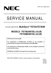
2.3.1
Names of each monitor part
Configuration of front control panel
a:Power button
b:Power indicator
c:EXIT button
d:CONTROL (Item select) buttons
e:CONTROL (Adjust) buttons
f :SELECT S/B MODE button
g:RESET button
b a
c
d
Figure 1 Front control panel
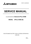
2.3.2
Configuration of rear input connector (signal input)
Shrink D-SUB 15P
SIGNAL A
Figure 2 Rear input connector
2-2
e
f
g
2.3.3
2.3.3.1
OSM display matrix
User mode
Adjustment items
OSM group USER1
BRIGHTNESS
CONTRAST
DEGAUSS
CONSTANT BRIGHTNESS
OSM group USER2
AUTO-ADJUST
LEFT/RIGHT
DOWN/UP
NARROW/WIDE
SHORT/TALL
OSM group USER3
COLOR
COLOR TEMP1,2,3,5
RED (GAIN)1,2,3,5
GREEN (GAIN)1,2,3,5
BLUE (GAIN)1,2,3,5
OSM group USER4
IN/OUT
LEFT/RIGHT
TILT
ALIGN
ROTATE
TOP
TOP BALANCE
BOTTOM
BOTTOM BALANCE
OSM group USER5
MOIRE CANCELER
CONVERGENCE(HOR.)
CONVERGENCE(VER.)
LINEARITY(VER.)
VERTICAL BALANCE
GLOBAL SYNC(TL)
GLOBAL SYNC(TR)
GLOBAL SYNC(BL)
GLOBAL SYNC(BR)
OSM group USER6
LANGUAGE
OSM POSITION
OSM TURN OFF
OSM LOCK OUT
IPM OFF MODE
EDGE LOCK
HOT KEY
FACTORY PRESET
OSM group USER7
DISPLAY MODE
MONITOR INFO
REFRESH NOTIFIER
Setting contents
Default setting
0.0 ∼ 100.0%
0.0 ∼ 100.0%
<+>
<+>
30.1%
100.0%
Setting classification
Common
By timings
○
○
○
<+>
0.0 ∼ 100.0%
0.0 ∼ 100.0%
0.0 ∼ 100.0%
0.0 ∼ 100.0%
50%
COLOR1,2,3,sRGB,5
5000K-9300K
0.0 ∼ 100.0%
0.0 ∼ 100.0%
0.0 ∼ 100.0%
○
○
○
○
○
○
○
○
○
COLOR1
COLOR1:9300K
○
○
○
○
0.0 ∼ 100.0%
0.0 ∼ 100.0%
0.0 ∼ 100.0%
0.0 ∼ 100.0%
0.0 ∼ 100.0%
0.0 ∼ 100.0%
0.0 ∼ 100.0%
0.0 ∼ 100.0%
0.0 ∼ 100.0%
○
Adjustment value
○
○
○
○
0.0 ∼ 100.0%
0.0 ∼ 100.0%
0.0 ∼ 100.0%
0.0 ∼ 100.0%
0.0 ∼ 100.0%
0.0 ∼ 100.0%
0.0 ∼ 100.0%
0.0 ∼ 100.0%
0.0 ∼ 100.0%
0.0%
Adjustment value(16.8∼82.7%)
Adjustment value(27.8∼71.7%)
○
○
○
○
○
Adjustment value(33.3∼66.2%)
Adjustment value(33.3∼66.2%)
Adjustment value(33.3∼66.2%)
Adjustment value(33.3∼66.2%)
○
○
○
○
ENG/DEU/FRA/ESP/ITA/JPN
ENG
<- /+>
(OSM is at the center of picture)
5SEC ∼ 120SEC
45SEC
ON/OFF
OFF
ENABLE/DISABLE
ENABLE
FRONT/BACK
BACK
OFF/ON
OFF
<+>
○
○
○
○
○
DPlus230SB
OFF
OFF/ON
2-3
○
○
○
2.3.3.2
Factory mode
Adjustment items
OSM group USER1
BRIGHTNESS
CONTRAST
DEGAUSS
CONSTANT BRIGHTNESS
OSM group USER2
AUTO-ADJUST
LEFT/RIGHT
DOWN/UP
NARROW/WIDE
SHORT/TALL
OSM group USER3
COLOR
COLOR TEMP1,2,3,5
R GAIN1,2,3,5
G GAIN1,2,3,5
B GAIN1,2,3,5
OSM group USER4
IN/OUT
LEFT/RIGHT
TILT
ALIGN
ROTATE
TOP
TOP BALANCE
BOTTOM
BOTTOM BALANCE
PCC CENTER
PCC SINE
OSM group USER5
MOIRE CANCELER
CONVERGENCE(HOR.)
CONVERGENCE(VER.)
LINEARITY(VER.)
VERTICAL BALANCE
GLOBAL SYNC(TL)
GLOBAL SYNC(TR)
GLOBAL SYNC(BL)
GLOBAL SYNC(BR)
OSM group USER6
LANGUAGE
OSM POSITION
OSM TURN OFF
OSM LOCK OUT
IPM OFF MODE
EDGE LOCK
HOT KEY
FACTORY PRESET
OSM group USER7
DISPLAY MODE
MONITOR INFO
REFRESH NOTIFIER
DESTINATION
Setting contents
Default setting
0.0 ∼ 100.0%
0.0 ∼ 100.0%
<+>
<+>
30.1%
100.0%
Setting classification
By timings
Common
○
○
○
<+>
0.0 ∼ 100.0%
0.0 ∼ 100.0%
0.0 ∼ 100.0%
0.0 ∼ 100.0%
50%
○
○
○
○
-----------
△
○
○
○
○
0.0 ∼ 100.0%
0.0 ∼ 100.0%
0.0 ∼ 100.0%
0.0 ∼ 100.0%
0.0 ∼ 100.0%
0.0 ∼ 100.0%
0.0 ∼ 100.0%
0.0 ∼ 100.0%
0.0 ∼ 100.0%
0.0 ∼ 100.0%
0.0 ∼ 100.0%
○
○
○
○
Adjustment value
○
○
○
○
○
○
○
0.0 ∼ 100.0%
16.8 ∼ 82.7%
27.8 ∼ 71.7%
0.0 ∼ 100.0%
0.0 ∼ 100.0%
33.3 ∼ 66.2%
33.3 ∼ 66.2%
33.3 ∼ 66.2%
33.3 ∼ 66.2%
0.0%
Adjustment value
Adjustment value
○
○
○
○
○
Adjustment value
Adjustment value
Adjustment value
Adjustment value
ENG
ENG/DEU/FRA/ESP/ITA/JPN
<- /+>
(OSM is at the center of picture)
5SEC ∼ 120SEC
45SEC
--OFF
ENABLE/DISABLE
ENABLE
FRONT/BACK
BACK
OFF/ON
OFF
<+>
DPlus230SB
OFF
EUR: for Europe
OFF/ON
EUR
2-4
○
○
○
○
○
○
○
○
○
○
○
○
Adjustment items
-
Setting contents
Default setting
1(ON)
1(ON)
Setting classification
By timings
Common
FACT 1
C-PURITY-DIS
PURITY-DIS
MAG-ZERO-HV
V-CANCEL
H-CANCEL
DBFV2 TOP
DBFV2 BOTTOM
DBFV4 TOP
DBFV4 BOTTOM
DBF-H-AMP
DBF-V-AMP
DBF-H-PHASE
SYNC-ON-GREEN
DIRECT-KEY
DDC-EEP-WP
H PURITY CHECK
V PURITY CHECK
CPDIS
PRDIS
HVZER
V-PUR
HPR-G
DBF2T
DBF2B
DBF4T
DBF4B
HFOCS
VFOCS
HFOCD
SOG-E
DIREC
WPDDC
HPURC
VPURC
0(0FF)/1(ON)
0(0FF)/1(ON)
PRO(EEh)
000 ∼ 0FF
000 ∼ 0FF
000 ∼ 7F
000 ∼ 7F
000 ∼ 7F
000 ∼ 7F
000 ∼ 0FF
000 ∼ 7F
000 ∼ 64
0(OFF)/1(ON)
0(OFF)/1(ON)
0(Unwritable)/1(Writable)
000 ∼ 002
000 ∼ 002
FACT 2
YHTT
YHTB
YHJT
YHJB
XH-L
XH-R
PQH-TL
PQH-TR
PQH-BL
PQH-BR
S3H-TL
S3H-TR
S3H-BL
S3H-BR
YVTT
YVTB
YVJT
YVJB
XV-L
XV-R
PQV-TL
PQV-TR
PQV-BL
PQV-BR
S3V-TL
S3V-TR
S3V-BL
S3V-BR
YH-TT
YH-TB
YH-JT
YH-JB
XH-L
XH-R
PQHTL
PQHTR
PQH-BL
PQH-BR
S3HTL
S3HTR
S3HBL
S3HBR
YV-TT
YB-TB
YV-JT
YV-JB
XV-L
XV-R
PQVTL
PQVTR
PQVBL
PQVBR
S3VTL
S3VTR
S3VBL
S3VBR
000 ∼ 0FF
000 ∼ 0FF
000 ∼ 0FF
000 ∼ 0FF
000 ∼ 0FF
000 ∼ 0FF
000 ∼ 0FF
000 ∼ 0FF
000 ∼ 0FF
000 ∼ 0FF
000 ∼ 0FF
000 ∼ 0FF
000 ∼ 0FF
000 ∼ 0FF
000 ∼ 0FF
000 ∼ 0FF
000 ∼ 0FF
000 ∼ 0FF
000 ∼ 0FF
000 ∼ 0FF
000 ∼ 0FF
000 ∼ 0FF
000 ∼ 0FF
000 ∼ 0FF
000 ∼ 0FF
000 ∼ 0FF
000 ∼ 0FF
000 ∼ 0FF
○
○
○
○
○
○
○
○
○
○
○
○
○
○
○
○
○
○
○
○
○
○
○
○
○
○
○
○
R-BS1
G-BS1
B-BS1
R-BS2
G-BS2
B-BS2
R-BS3
G-BS3
B-BS3
000 ∼ 0FF
000 ∼ 0FF
000 ∼ 0FF
000 ∼ 0FF
000 ∼ 0FF
000 ∼ 0FF
000 ∼ 0FF
000 ∼ 0FF
000 ∼ 0FF
○
○
○
○
○
○
○
○
○
FACT 3
R-BIAS-H
G-BIAS-H
B-BIAS-H
R-BIAS-M
G-BIAS-M
B-BIAS-M
R-BIAS-L
G-BIAS-L
B-BIAS-L
2-5
○
○
○
○
○
○
○
○
○
○
○
0(OFF)
1(ON)
0(Unwritable)
0
0
○
○
○
Setting contents
Adjustment items
R-GAIN-H
G-GAIN-H
B-GAIN-H
R-GAIN-M
G-GAIN-M
B-GAIN-M
R-GAIN-L
G-GAIN-L
B-GAIN-L
BRIGHT-CENT
BRIGHT-MAX
ABL
SBM CONTRAST1
SBM BRIGHT1
SBM CONTRAST2
SBM BRIGHT2
000 ∼ 0FF
000 ∼ 0FF
000 ∼ 0FF
000 ∼ 0FF
000 ∼ 0FF
000 ∼ 0FF
000 ∼ 0FF
000 ∼ 0FF
000 ∼ 0FF
000 ∼ 0FF
000 ∼ 0FF
000 ∼ 0FF
000 ∼ 7DC
000 ∼ FFF
000 ∼ 7DC
000 ∼ FFF
R-GN1
G-GN1
B-GN1
R-GN2
G-GN2
B-GN2
R-GN3
G-GN3
B-GN3
BTCEN
BTMAX
ABLAJ
SBCN1
SBBR1
SBCN2
SBBR2
FACT HV
HV-ADJ CAUTION
XPRO-CALIBRATION
XPRO-TST CAUTION
XPRO-ADJ CAUTION
000∼0A8
000∼OFF
000∼OFF
HVADJ+20∼OFF
2-6
Setting classification
By timings
Common
○
○
○
○
○
○
○
○
○
○
○
○
○
○
○
○
○
○
○
○
2.4
Adjustment
2.4.1
How to select the factory adjustment (FACTORY) mode
2.4.1.1
Selecting with front panel switches
(1) Turn the power ON while holding down EXIT button.
(2) After step (1), release EXIT button after one to two seconds.
(3) Confirm that 255 is displayed for the counter of FACT DATA on OSM display.
(4) Set to 05 with (+) button.
(5) When SELECT S/B MODE button is pressed, the factory mode will be entered.
This factory adjustment mode is entered with the above steps.
*The factory adjustment mode remains valid even after the power is turned OFF.
Note that steps (3) to (4) must be carried out within ten seconds. If ten seconds are exceeded,
the mode will return to the user mode.
<Returning to the user mode from the factory mode>
(1) Display FACT DATA on OSM picture with the group selection.
(2) Set the counter value to 010 with (-) (+) buttons.
(3) When SELECT S/B MODE button is pressed, the mode will return to the user mode.
2.4.2
Adjustments before aging
Status
indicator
2.4.2.1
Adjustment item
Adjustment mode/set
Before aging
Imput signal/pattern
The only the sync. signal of
No. 12:106.25kHz / 85Hz, 1600x1200
Adjusting the high voltage and high voltage protector
Status
indicator
Adjustment item
Adjustment mode/set
Imput signal/pattern
High voltage and high
The only the sync. signal of
voltage protector
No. 12:106.25kHz / 85Hz, 1600x1200
(Timing No. 12 (106.25 kHz/85 Hz, 1600x1200) SYNC signal is only input)
(1) Turn the monitor power OFF and connect a high voltage indicator to the anode of CRT
before turning the monitor power ON.
(2) Select "FACT DATA***" on OSM and set to 250 using (-) button before pushing the SELECT S/B MODE button.
(3) Select HVADJ (HV-ADJ CAUTION) on OSM to adjust the high voltage to 27.0kV±0.5kV.
(4) Select XPCAL (XPRO-CALIBRATION) on OSM and turn the screen VR all the way down
counterclockwise before adjusting the high voltage to 31.0kV±0.5kV by manipulating (+) () buttons.
(5) With SELECT S/B MODE button pushed, the protector operation point is set, causing the
high voltage to return to 27.0kV±0.5kV.
(6) Rotate the screen VR so that OSM can be confirmed.
(7) Select XPROT (XPRO-TST CAUTION) on OSM by the manipulation shown above and turn
the screen VR all the way down counter-clockwise.
(8) Raise the voltage manipulating (+) button and make sure that the high-voltage protection
circuit gets activated at 31.0kV±0.5kV.
2-7
2.4.2.2
FOCUS adjustment (Rough adjustment)
(1) Set the brightness so that the raster can be confirmed with the FBT picture potentiometer
(screen VR).
(2) Adjust the focus pack "FOCUS 1, 2" so that both edges of the picture are clear.
2.4.2.3
Shock test
(1) Display the "color bar" with the signal generator A.
(2) Confirm that there is no abnormality in the image when shock is applied on the monitor.
2.4.2.4
Preadjustment before aging
(1) Change to FACTORY MODE (aging mode) in advance.
(2) Display a full white with the signal generator A.
(3) Confirm that the R, G and B channel images are output.
(4) Confirm that the picture position, picture size, PCC and balance can be controlled, and
roughly adjust.
(5) Adjustment of BTCEN (BRIGHT-CENT), BTMAX (BRIGHT-MAX), BS1 (BIAS-H)
a) Input timing No. 12 (1600x1200 106.25K/85) with the signal generator (R, G and B
OFF).
b) Set each adjustment item to the following value.
BRIGHTNESS
: 7F
(FACT3)
R-BS1(R-BIAS-H)
: 00
G-BS1(G-BIAS-H)
: 8A
B-BS1(B-BIAS-H)
: 00
BTCEN (BRIGHT-CENT) : 5E0
BTMAX (BRIGHT-MAX)
: 800
c) Connect PWB-CRT TP (R200G lead wire) to the probe.
d) Select BTCEN (BRIGHT-CENT) in FACT3, set the black level voltage of PWB-CRT TP
(R200G lead wire) to 70 +/- 0.5V with the oscilloscope (refer to the following picture).
* In use of the digital voltage meter, set it to 73 +/- 0.5V.
G-K
70±0.5V
GND
e) Set the back raster luminance to 0.5 +/- 0.3 cd/cm 2 with BRIGHTNESS adjustment.
f) Adjust the back raster color coordination to the following value with R-BS1 (R-BIAS-H)
and B-BS1 (B-BIAS-H).
x: 0.283±0.02 / y: 0.297±0.02
* Do not adjust BTCEN (BRIGHT-CENT) after the adjustment of back raster color coordination carried out at f) above, but it can be adjusted in main adjustment mentioned
after 2.4.3.
* BRIGHTNESS should be adjusted when the back raster is varied in adjustment of
purity and convergence.
(6) Confirm that OSM power management is OFF.
(7) Disconnect the signal and confirm that the following picture appears on OSM. Then adjust
OSM picture luminance with BRIGHTNESS adjustment, and carry out heat run for 60
minutes or more.
2-8
OWN
VER
S2-OW-**
1.*.**
(Initial data file name)
2.4.2.5
Adjusting the landing (ITC/4 corner purity adjustment)
Adjustment item
Status
indicator
Adjustment mode/set
Imput signal/pattern
No. 12:106.25kHz / 85Hz, 1600x1200
landing
Full green
(1)
(2)
(3)
(4)
Input the timing No. 12 (106. 25kHz/85Hz, 1600x1200) full green signal.
Turn OFF the monitor power to carry out hand degaussing.
Select GLOBAL SYNC (TL) on OSM.
Adjust to the best condition using (-) (+) buttons. Here, make sure that the adjusted value
is within the range of OSM display value = 55h (85) to A9h (169).
(5) Carry out similar adjustment for TR/BL/BR (GLOBAL SYNC).
Note) When the substrate is replaced at the time of repair, set TL/TR/BL/BR to the values
before replacement before carrying out adjustment.
(6) Input the timing No.12 (106.25kHz/85Hz, 1600x1200) full white signal.
2.4.3 Adjusting the picture size, position, distortion, DBF amplitude and phase
The manual adjustment methods are explained below. The adjustments are executed in the
factory adjustment (factory) mode.
Adjust the picture size to the value indicated in the list of adjustment values.(Refer to 2.5.1.10
Adjustment value list.)
Adjust the distortion to the value indicated in the picture performance inspection item. (Refer
to 2.5.1.8 Picture distortion.)
2.4.3.1
Adjusting the picture inclination
Status
indicator
Adjustment item
Adjustment mode/set
Imput signal/pattern
Factory
No. 12:106.25kHz / 85Hz,1600x1200
Picutre inclination
Crosshatch with frame
Set OSM to ROTATE, and using (-) (+) buttons, set the raster inclination to be horizontal to
the CRT face surface.
2.4.3.2
Adjusting the back raster position
Status
indicator
Adjustment item
Back raster position
Adjustment mode/set
Imput signal/pattern
Factory
No. 12:106.25kHz / 85Hz, 1600x1200
Only the sync. signal input
(1) Set BRIGHTNESS to 100% to show the back raster.
(2) Select LEFT/RIGHT and DOWN/UP, adjust the horizontal back raster position to the center
of the bezel using (-) (+) buttons.
At this time, the raster width should be |L1-L2| ≤ 2.0mm.
Back raster
L1
L2
2-9
2.4.3.3
Adjusting the left/right distortion, picture width, picture position (LEFT/RIGHT)
and vertical linearity (all preset)
(1) Set DOWN/UP of the user mode to 50%.
<Setting in the factory mode with the following steps>
(2) Adjust the vertical size to approx. 297mm, and the vertical position to the approximate
center.
(3) Select LINEARITY (VER.) and VERTICAL BALANCE with OSM, and adjust so that the
vertical linearity is equal at the very top of the picture, at the very bottom of the picture,
and at the center of the picture.
(4) Select SHORT/TALL and DOWN/UP with OSM, and adjust the vertical width and vertical
position to the specified values using (-) (+) buttons.
(5) Select IN/OUT, ALIGN, PCC CENTER, TOP and BOTTOM with OSM, and adjust the vertical line at both side of the picture to the straight line using (-) (+) buttons.
(6) If the left and right distortions differ, select LEFT/RIGHT (PIN VAL), TILT, TOP-BALANCE
and BOTTOM-BALANCE with OSM, and adjust so that the distortions are visually balanced.
(7) Select LEFT/RIGHT with OSM, and adjust the horizontal raster position to the center of the
picture using (-) (+) buttons.
(8) Select NARROW/WIDE with OSM, and adjust the horizontal raster width to the value given
in the adjustment list using using (-) (+) buttons. (Refer to 2.5.1.10 Adjustment value list.)
* Note (1) PCC SINE, LEFT/RIGHT (PIN VAL) and PCC CENTER are used only for touch
up.
Note (2) The picture position and distortion must be within the ranges given in the
picture performance inspection items. (Refer to 2.5.1.8 Picture distortion.)
2.4.3.4
Adjusting the DBF amplitude and phase
(1) Connect the oscilloscope to the lead of R7A2 (SG702 side) on PWB-MAIN and to one of
the signal outputs for the signal sources full R, G, B (VIDEO).
(2) Set OSM to the select picture of HFOCUS (DBF-H-AMP) in FACT 1, and using (-) (+)
buttons adjust the horizontal parabola wave amplitude (image area) to the value given in
the list of adjustment values. (Refer to 2.5.1.10 Adjustment value list.)
Vertical parabola wave
Measure
the center.
DBF-V-AMP
Image signal 1V
DBF-V-AMP adjustment
2 - 10
Horizontal parabola wave
DBF-H-AMP
4
1
2
3
DBF-H-PHASE
Image signal
The center of the horizontal
parabola waveform and
center of the image signal
waveform must match.
5
DBF-H-AMP / PHASE adjustment
(3) Set the output of the signal generator to crosshatch (white/normal).
(4) Set OSM to the select picture of HFOCD (DBF-H-PHASE) in FACT1, and adjust the focus
balance of point 1 and point 3 in the above figure using (-) (+) buttons.
* (3) and (4) should be carried out with all preset timing.
(5) Set OSM to the select picture of DBF2T (DBFV2 TOP) in FACT1, and adjust using (-) (+)
buttons so that the focus level of point 4 and point 2 in the above figure can be balanced.
(6) Set OSM to the select pictutre of DBF2B (DBFV2 BOTTOM) in FACT1, and adjust using (-)
(+) buttons so that the focus level of point 2 and point 5 in the above figure can be balanced.
* (5) and (6) should be carried out with timing No. 12 (106.25kHz/85Hz, 1600x1200).
2.4.4
Adjusting the cut off
Status
indicator
Adjustment item
Cut off
Adjustment mode/set
Imput signal/pattern
Factory
No. 12:106.25kHz / 85Hz, 1600x1200
2.4.4.1 Adjusting BTCEN (BRIGHT-CENT), BTMAX (BRIGHT-MAX) and BS1 (BIAS-H)
<In case pre-adjustment before aging is carried out >
(1) Input timing No. 12 (106.25kHz/85Hz, 1600x1200) with the signal generator (R, G and B
OFF).
(2) Set each adjustment item to the following value.
BRIGHTNESS
: 7F
(FACT3)
R-BS1(R-BIAS-H)
: 00
G-BS1(G-BIAS-H)
: 8A
B-BS1(B-BIAS-H)
: 00
BTMAX (BRIGHT-MAX)
: 800
(3) Set the back raster luminance to 0.3 +/- 1cd/m 2 with FBT screen VR.
(4) Adjust the back raster color coordination to the value listed in the following table with RBS1 (R-BIAS-H) and B-BS1 (B-BIAS-H).
(5) Adjust the back raster luminance to 0.3 +/- 0.1cd/m 2 with BTCEN.
(6) If the back raster color coordination is deviated from the values listed in the following table,
repeat steps (4) and (5).
(7) Adjust the back raster luminance to 3.0 +/- 0.2cd/m 2 with BTMAX.
2 - 11
<In case pre-adjustment before aging is not carried out >
(1) Input timing No. 12 (106.25kHz/85Hz, 1600x1200) with the signal generator (R, G and B
OFF).
(2) Set each adjustment item to the following value.
BRIGHTNESS
: 7F
(FACT3)
R-BS1(R-BIAS-H)
: 00
G-BS1(G-BIAS-H)
: 8A
B-BS1(B-BIAS-H)
: 00
BTCEN (BRIGHT-CENT)
: 5E0
BTMAX (BRIGHT-MAX)
: 800
(3) Connect PWB-CRT TP (R200G lead wire) to the probe.
(4) Select BTCEN (BRIGHT-CENT) in FACT3, set the black level voltage of PWB-CRT TP
(R200G lead wire) to 70 +/- 0.5V with the oscilloscope (refer to the following picture).
* In use of the digital voltage meter, set it to 73 +/- 0.5V.
G-K
70±0.5V
GND
(5) Set the back raster luminance to 0.3 +/- 1cd/m 2 with FBT screen VR.
(6) Adjust the back raster color coordination to the value listed in the following table with RBS1 (R-BIAS-H) and B-BS1 (B-BIAS-H).
(7) Adjust the back raster luminance to 0.3 +/- 0.1cd/m 2 with BTCEN.
(8) If the back raster color coordination is deviated from the values listed in the following table,
repeat steps (6) and (7).
(9) Adjust the back raster luminance to 3.0 +/- 0.2cd/m 2 with BTMAX.
* The following table is applicable for the monitor without the back cover.
Adjustment value of BS1 (BIAS-H)
Adjustment item
BS1 (BIAS-H)
Color temperature
(9300K)
Color coordination
x
0.283±0.015
y
0.297±0.015
2.4.4.2 Adjusting BS2 (BIAS-M) / BS3 (BIAS-L)
(1) Set R-BS2 (R-BIAS-M), G-BS2 (G-BIAS-M) and B-BS2 (B-BIAS-M) to the value listed in the
following table.
(2) Set R-BS3 (R-BIAS-L), G-BS3 (G-BIAS-L) and B-BS3 (B-BIAS-L) to the value listed in the
following table.
As the values listed in the following table are the finite differences from the values of BS1
(BIAS-H), this adjustment should be carried out after adjustment of BS1 (BIAS-H).
Adjustment data of BS2 (BIAS-M) / BS3 (BIAS-L)
(*The following data is the finite difference from BS 1 (BIAS-H).) Adjustment item
BS2 (BIAS-M)
BS3 (BIAS-L)
Color temperature
(6500K)
(5000K)
+3
same value
-4
+5
same value
-8
Data
R-BS
G-BS
B-BS
2 - 12
2.4.5 Setting CONSTANT BRIGHTNESS circuit (Factory mode)
Note) This operation should be carried out after the adjustment of cut-off. In addition, heatrunning should be fully carried out.
2.4.5.1
Reading beam current default data
(1) Input timing No. 12 (106.25kHz/85Hz, 1600x1200) crosshatch signal with the signal generator.
(2) Select CONSTANT BRIGHTNESS and push (-) button, then it starts to read the beam
current default data.
(3) When the reading is completed, OSM standard voltage DAC (Digital Analog Converter)
data and the beam current default data of each color (R/G/B) are indicated. Then, confirm
that the data is within the following value range.
Standard voltage DAC data
: 50-F0 (HEX)
Red beam current default data
: 73-8C (HEX)
Green beam current default data : 73-8C (HEX)
Blue beam current default data
: 73-8C (HEX)
(4) If the above data could not be within the value range specified above (3), carry out steps
(2) and (3) mentioned above once.
(5) Measure the luminance and color coordination of the back raster.
2.4.5.2
Confirming CONSTANT BRIGHTNESS function
(1) Select COSTANT BRIGHTNESS. Push (+) button, and it decrements the BRIGHTNESS
data to imitate the deteriorated condition due to elapsed time, then compensation function
starts to operate.
(2) Measure the color coordination and luminance of the back raster after compensation.
Compare them to the data measured in 2.4.5.1 (5) to confirm that the differences are within
the following value range.
Color coordination of x and y
: within +/- 0.020
Luminance
: within +/- 0.05cd/m 2
(3) If the color coordination and Iuminance of the back raster could not be within the value
range specified in (2) above, select CONSTANT BRIGHTNESS and push RESET button,
then carry out step 2.4.5.1 (2) once.
(4) Select CONSTANT BRIGHTNESS, and push RESET button.
2.4.6
2.4.6.1
Adjusting the RGB drive signal
Adjusting GN1 (GAIN-H) (adjustment of 9300K)
Status
indicator
Adjustment item
GN1 (GAIN-H)
Adjustment mode/set
Factory
Imput signal/pattern
No. 12:106.25kHz / 85Hz, 1600x1200
Full white
(1) Input the following adjustment timing with the signal generator.
Pattern: Full white (Input amplitude = 0.7Vp-p)
Adjustment timing: No.12 (106.25kHz/85Hz, 1600x1200)
(2) Select CONTRAST with OSM, and set to MAX using (+) button.
(3) Select BRIGHTNESS, and set the data to 7F using (-) (+) buttons.
(4) Output the solid color for the picture from Signal generator A, and input GREEN only.
(5) Set G-GN1 (G-GAIN-H) with OSM, and adjust the luminance of full green picture to the
specified value listed in the following table with (-) (+) buttons.
(6) Input BLUE, RED and GREEN, and select B-GN1 (B-GAIN-H), R-GN1 (R-GAIN-H) and GGN1 (G-GAIN-H) appropriately, then adjust each data to the specified value listed in the
following table with (-) (+) buttons.
(7) Confirm that the variation of the color coordination data of x and y is within +/- 0.015 when
CONTRAST is set to 25cd/m 2 with OSM.
2 - 13
(8) Adjust GN2 (GAIN-M) and GN3 (GAIN-L) to the specified value listed in the following table
in the same manner as GN1 (GAIN-H).
COLOR TEMPERATURE GN1 (GAIN-H) GN2 (GAIN-M) GN3 (GAIN-L) TOLERANCE
Color temperature
Full green luminance
Full White
x
color coordination y
2
Full white luminance(cd/m )
(9300K)
(6500K)
(5000K)
77.0
66.0
54.0
±1.0
0.283
0.313
0.345
±0.005
0.297
0.329
0.359
±0.005
105 or more
90 or more
75 or more
(9) Setting R/G/B MAX GAIN
Set the MAX GAIN value for the following formula to the following address (all setting
values are indicated by HEX).
Firstly hexadecimal number should be converted to decimal number to be calculated, then
the result figured out is return to hexadecimal numbers to be written into the applicable
address.
How to write into address is described below.
MAX GAIN = MAX value of R/G/B GAIN adjustment value (*1) x {1 + (MAX value of
SBCN1, 2 (*2) /FF)
Address (HEX): 89 (R-GAIN-MAX), 8a (G-GAIN-MAX), 8b (B-GAIN-MAX)
(*1): MAX value of R/G/B GAIN adjustment value is the maximum one among R-GN1, GGN1, B-GN1, R-GN2, G-GN2, B-GN2, R-GN3, G-GN3 and B-GN3 in OSM (FACTORY3) adjusted according to the procedure (1) to (8) mentioned above.
(*2): MAX value of SBCN1, 2 is the maximum one between SBCN1 and SBCN2 in OSM
(FACTORY-3).
Note) All of (MAX GAIN), (MAX value R/G/B GAIN) and (SBCN1 and SBCN2) are indi
cated by hexadecimal number (HEX), the value is to be converted to the decimal
number (DEC) first to be calculated, then, converted to the hexadecimal number (HEX).
<How to rewrite into address>
(a) Change to FACTORY MODE in advance.
(b) Set the counter of FACT DATA on OSM to 99 using (-) (+) buttons, and push SELECT
button.
(c) Press either (
) or (
) button, and confirm that the following picture appears.
(d) Using (-) (+) buttons rewrite the counter for every hexadecimal data to the one figured
out with the calculation mentioned above (decimal data is to be rewritten following to
hexadecimal one synchronously).
(e) Press EXIT button, then the rewritten data is to be registered.
(f) To disable this rewriting function, turn the power OFF. However, FACTORY MODE is
still alive even if the power was turned off.
NOTE) Be careful NOT to wrongly rewrite the data since this rewriting function is
available for all of the EDID data.
2 - 14
2.4.6.2
Adjusting ABL
Status
indicator
Adjustment item
Adjustment mode/set
Imput signal/pattern
Factory
ABL
No. 12:106.25kHz / 85Hz, 1600x1200
Full white
(1) Input the following adjustment timing with the signal generator.
Pattern: Full white (input amplitude = 0.7Vp-p)
Adjustment timing: No.12 (106.25kHz/85Hz, 1600x1200)
(2) Select ABLAJ (ABL) with OSM, and adjust to 115cd/m 2 +/- 5.
Here, the picture size should follow 2.5.1.10 Adjustment value list.
2.4.7
Adjusting the focus
NOTE) For adjustment of focus with FOCUS VR, be sure to use ISOLATED alignment driver.
Normal or reverse display
Vertical
line
Horizontal
line
Point to align with
Adjust to FOCUS JUST at the
circled sections using FBT
FOCUS1-VR mainly and FBT
FOCUS2-VR with well
balancing.
Reverse display
(Green)
Normal display
The ratio of core : Halo of the vertical lines at both
sides shouled be 1 : 1.
Adjust to FOCUS JUST at the
center of screen (circled section)
using FBT FOCUS1-VR mainly and
FBT FOCUS2-VR with well
balancing.
Adjust to halo condition once, then
adjust to FOCUS JUST.
* Adjust halo to a quarter of core with camera adjustment.
Halo should be a half of core maximum.
<Adjusting the static focus>
Status
indicator
Adjustment item
Adjustment mode/set
Imput signal/pattern
No. 12:106.25kHz / 85Hz, 1600x1200
Static focus
H character, crosshatch
For steps (1) and (2), use the timing No. 12 (106.25kHz/85Hz, 1600x1200) H character pattern
and crosshatch pattern.
For step (3), use all preset timing H character patterns and crosshatch patterns.
(1) Display a green or white crosshatch pattern, and adjust the focus according to the procedure mentioned above.
(2) If the DBF voltage is insufficient or excessive, select HFOCS (DBF-H-AMP) from OSM, and
readjust with (-) (+) buttons. Then repeat step (1), and adjust so that the following judgement conditions are satisfied.
(3) For all of the other preset timings, if the DBF voltage is insufficient or excessive, select
HFOCS (DBF-H-AMP) from OSM, and readjust with (-) (+) buttons.
(4) If the focus is unbalanced at right side and left side with other preset timings.
Select HFOCD (DBF-H-PHASE) and readjust with (-) (+) buttons.
(5) If the focus is unbalanced at top and bottom with timing No. 12 (106.25kHz/85Hz, 1600 x 1200),
select DBF2T (DBFV2 TOP) and DBF2B (DBFV2 BOTTOM) and readjust with (-) (+) buttons.
2 - 15
(6) After inputting check timing No. 5 in user mode and operates AUTO-ADJUST function,
confirm the focus with "e" character pattern in reverse. If "e" character is indistinct, repeat
step (1) to readjust.
*Adjustment votlage max value:
DBF-H-AMP H width: 396mm: 430V
DBF-V-AMP V width: 297mm: 200V
The focus is judged as follows.
Timing
Judgment pattern (Note 1) (Note 2)
Normal display (All preset)
Crosshatch pattern
Reverse display
Resolution: 1600x1200
Resolution: >1600x1200
Judge with pattern A
Judge with pattern B
(Note 1) Pattern A: Font 7 ×9, Cell 10×11, e character
Pattern B: Font 7 ×9, Cell 10×11, H character
(Note 2) Focus judgement: Crosshatch pattern should be used for normal display judgement
The ratio of core : Halo is as follows.
Should be 1 : 0.5 or less at the center of the picture.
Should be 1 : 1.5 or less at the both sides of the picture
To judge the reverse display, do not carry out a relative evaluation with the other point on the
screen. Instead, judge whether the e (H) character can be read distinctly at that point.
Core
Halo
Core
Halo
Focus pack
FOCUS1-VR
FOCUS
FOCUS2-VR
Focus attention point
2.4.8
Adjusting the convergence
2.4.8.1
Adjusting with ITC
Before adjusting the center mis-convergence and axial mis-convergence, carry out sufficient
full white aging (100cd/m 2 or more, for one hour or more). Then, adjust with the following
timing.
Timing: No. 12 (106.25kHz/85Hz,1600x1200) crosshatch pattern
Confirm that the following DDCP default setting is as shown in the table of 2.3.2.2 Factory
mode (OSM display matrix).
All items of OSM group USER5 and FACT2 of Factory mode
Adjust the horizontal and vertical convergence to the optimum setting with the CRT CP ring,
etc.
(Refer to following drawings.)
R or B
G
B or R
Horizontal convergence
Vertical convergence
2 - 16
Adjusting the center misconvergence and axial misconvergence
Adjustment item name
Problem
R
Adjustment point
Adjustment procedure
B
H-STATIC
V-STATIC
Adjust to +/- 0.1mm or less
with CP-ASSY 4P.
Adjust so that TOP+BOTTOM
are +/- 0.1mm or less with YH
volume.
YH axial deviation
Adjustment making much of
horizontal trapezoidal distortion
Adjust optimally using DY
left/right shaking YV volume.
The remaining YV
misconvergence should be
adjusted with DDCP.
YV axial deviation
XH axial deviation
Adjust so that LEFT-RIGHT is
+/- 0.1mm or less with XH
slider.
XV characteristics
Only when XV (B-Bow) is +/0.15mm or more, adjust so
that LEFT-RIGHT is +/0.15mm or less with the
interlock of B-Bow 4P and
CP-ASSY 4P.
XV axial deviation
Adjust so that LEFT+RIGHT
is +/- 0.15mm or less with XV
differential coil.
B-Bow 4p and CP-ASSY 4p
Correction Method
XH Slider
DY Board
YH(a)
B-Bow 4p
CP-ASSY 4p
XH Slider
CRT
DY
Front
YH(t)
(Side View)
TRD
Rear
XV Dif. Coil: XV (t)
Adjustmennt stick
DY Board
(Viewed from top side)
(Top of DY)
2 - 17
(Push or Pull)
(Viewed from neck side)
2.4.8.2
Adjusting DDCP
(1) Input the timing No. 12 (106.25kHz/85Hz,1600x1200) crosshatch pattern.
(2) Enter the factory mode.
(3) Adjust in the following order. (It is assumed that the center and axial misconvergence on
the previous page have already been adjusted.)
Adjustment Adjustment item name
order
Problem
Adjustment point
Adjustment procedure
4H-COIL
1
CONVERGENCE HOR.
R
B
Adjust to 0.05mm or less.
(Adjustment target is 0mm.)
YH (Top)
YH-TT
Adjust YH (Top) to 0.05mm or
less with balance adjustment
of YH-TT and YH-JT.
(Adjustment target is 0mm.)
2
YH-JT
YH-M (Top)
YH -M (Bottom)
YH-TB
(NOTE)
The operating amount at YHM(Top) when moving YH-TT
and YH-JT : YH-TT < YH-JT
Adjust YH (Bottom) to 0.05mm
or less with balance
adjustment of YH-TB and YHJB. (Adjustment target is
0mm.)
3
YH-JB
YH (Bottom)
(NOTE)
The operating amount at YH-M
(Bottom) when moving YH-TB
and YH-JB :
YH-TB < YH-JB
XH(Left)
4
XH-L
Adjust to 0.1mm or less.
XH(Right)
5
XH-R
Adjust to 0.1mm or less.
2 - 18
Adjustment Adjustment item name
order
Problem
Adjustment point
Adjustment procedure
4H-COIL
S3H(Top Left)
R
6
B
S3H-TL
Adjust to 0.3mm or less.
S3H(Top Right)
7
S3H-TR
Adjust to 0.3mm or less.
S3H(Bottom Left)
8
S3H-BL
Adjust to 0.3mm or less.
S3H(Bottom Right)
9
S3H-BR
Adjust to 0.3mm or less.
PQH (Top Left)
B
10
PQH-TL
Adjust to 0.3mm or less.
R
PQH (Top Right)
11
Adjust to 0.3mm or less.
PQH-TR
2 - 19
Adjustment
Adjustment item name
order
Problem
Adjustment point
Adjustment procedure
4H-COIL
12
PQH-BL
Adjust to 0.3mm or less.
R
B
PQH (Bottom Left)
13
Adjust to 0.3mm or less.
PQH-BR
PQH (Bottom Right)
Adjustment Adjustment item name
order
Problem
Adjustment point
Adjustment procedure
4V-COIL
R
1
Adjust to 0.05mm or less.
(Adjustment target is 0mm.)
CONVERGENCE VER.
B
YV (TOP)
2
YV-TT
YV-JT
YV-M (TOP)
YV-M (BOTTOM)
3
YV-TB
YV-JB
YV (BOTTOM)
2 - 20
Adjust YV (Top) to 0.05mm or
less with balance adjustment
of YV-TT and YV-JT.
(Adjustment target is 0mm.)
(Note) The operating amount
at YV-M (Top) when
moving YV-TT and YVJT.
YV-TT<YV-JT
Adjust YV (Bottom) to 0.05mm
or less with balance
adjustment of YV-TB and YVJB.
(Adjustment target is 0mm.)
(Note) The operating amount
at YV-M (Bottom)
when moving YV-TB
and YV-JB.
YV-TB<YV-JB
Adjustment Adjustment item name
order
Problem
Adjustment point
Adjustment procedure
4V-COIL
XV(Left)
B
4
XV-L
Adjust to 0.1mm or less.
R
XV(Right)
5
XV-R
Adjust to 0.1mm or less.
S3V(Top Left)
B
6
S3V-TL
Adjust to 0.3mm or less.
R
S3V(Top Right)
7
S3V-TR
Adjust to 0.3mm or less.
S3V(Bottom Left)
8
S3V-BL
Adjust to 0.3mm or less.
S3V(Bottom Right)
9
S3V-BR
Adjust to 0.3mm or less.
2 - 21
Adjustment
Adjustment item name
order
Problem
Adjustment point
Adjustment procedure
4V-COIL
B
R
10
PQV (Top Left)
PQV-TL
Adjust to 0.3mm or less.
PQV (Top Right)
11
PQV-TR
Adjust to 0.3mm or less.
12
PQV-BL
Adjust to 0.3mm or less.
PQV (Bottom Left)
13
PQV-BR
Adjust to 0.3mm or less.
PQV (Bottom Right)
*
Specify the adjustment value range of the following adjustment items in general DDCP
adjustment.
Adjustment items
Adjustment value range (Factory mode))
CONVERGENCE (HOR.)
2Bh (43) - D3h (211) (OSM display value=DAC output value)
CONVERGENCE (VER.)
47h (71) - B7h (183) (OSM display value=DAC output value)
2 - 22
2.4.9
Default settings (With factory mode)
Status
indicator
Adjustment item
Default settings
Adjustment mode/set
Factory mode
Imput signal/pattern
Each adjustment timing
(1) Set the default values as shown in the table (user mode) given in OSM display (Refer to
2.3.2.1 User mode).
If the setting class is an item with each timing, carry out with each adjustment timing.
(2) Return to the user mode with the front panel.
(3) Execute FACTORY PRESET to confirm that each OSM setting is as shown in the table
(user mode) given in OSM display (Refer to 2.3.2.1 User mode).
Only CONTRAST will be set to 100% when RESET button is pressed in the normal mode.
(4) How to set OSM BRIGHTNESS RESET value (30.1%) in user mode.
(a) Change to FACTORY MODE in advance.
(b) Set the counter of FACT DATA on OSM to 99 using (-) (+) buttons, and push SELECT
button.
(c) Using (
)(
) buttons to set ADDR to 0B1.
(d) Using (-) (+) buttons set DATA to 04D.
(e) Press EXIT button to record 04D set in (d) mentioned above.
(f) To disable this rewriting function, turn the power OFF (FACTORY MODE is still alive
even if the power was turned OFF).
Return to USER MODE.
Select BRIGHTNESS with OSM, and press RESET button, then the data (04D = 30.1%) set in
(d) mentioned above is called.
(For your information; when (-) and (+) buttons are pressed simultaneously, the data is set to
50%.)
(5) After setting the default values, turn the power button OFF.
2 - 23
2.5
Inspections (In normal mode)
Status
indicator
Adjustment mode/set
Adjustment item
Imput signal/pattern
Normal mode
Inspections
2.5.1 Electrical performance
Inspect the electrical performance after confirming that the contrast is set to MAX and the
bright is set to center (by pressing (-) (+) buttons simultaneously).
After inspection, carry out FACTORY PRESET operation.
2.5.1.1
Withstand voltage
There must be no abnormality when 1500VAC is applied for two seconds between both ends of
the AC input terminal and chassis, and between the DG coil terminal and chassis.
The cut-off current should be 20mA.
2.5.1.2
Grounding conductivity check
Check that the resistance value is 100ohms or less when 25A is passed between the AC input
terminal grounding GND and chassis GND.
2.5.1.3
Degaussing coil operation
Confirm that when OSM DEGAUSS is executed, the picture vibrates and then stops.
2.5.1.4
IPM OFF MODE function operation (Set the AC power input to 230V)
Confirmation timing
Timing No. 12 (106.25kHz / 85Hz, 1600x1200)
Use the full white pattern without R, G, B signals.
Select IPM OFF MODE from OSM, and set to 1:ENABLE.
(1) IPM OFF MODE ENABLE
(a) Confirm that when H and V SYNCs are removed, the system waits for approx. five
seconds, displays IPM OFF MODE for approx. three seconds, and then the picture dark
ens.
Also confirm that Power Indicator changes to orange and the power consumption is
as follows.
Power consumption
2W or less
(b) Confirm that when H and V SYNCs are input again, the high voltage is recovered, and
the picture appears in approx. five seconds.
2 - 24
2.5.1.5
Confirming the GLOBAL SYNC (CORNER-Purity) function
Confirmation timing
Timing No. 12 (106.25kHz / 85Hz, 1600x1200)
Input a (full white display), and press (-)(+) buttons to change GLOBAL SYNC (TR/TL/BR/BL).
Confirm that the color coordination around the picture changes.
2.5.1.6
Focus, picture performance
Adjustment mode/set
Adjustment item
Status
Check timing No.5, "e" character reverse display
Check timing No.6, chrosshatch normal display
Focus,
indicator
Imput signal/pattern
picture performance
The picture must be evenly bright with check timing No. 5 "e" character reverse display and
check timing No. 6 chosshatch normal display.
2.5.1.7
Misconvergence
After heat running for 20 minutes or more, the mis-convergence amount in the horizontal and
vertical directions must be below the following values.
The mis-convergence amount is the value between the two colors of R, G and B separated the
most in the horizontal (X) and vertical (Y) directions when a 15 vertical lines x 11 horizontal
lines crosshatch is displayed.
This adjustment should be carried out with the convergence meter MINOLTA CC-100.
Mis-convergence amount
Zone
A
0.25mm or less
B
0.35mm or less
Measurement timing (Timing No.)
12
<Mis-convergence amount>
<Zone>
B
A
Y
Specified picture size
396mm x 297mm
X
2 - 25
2.5.1.8
Picture distortion
When the picture distortion is measured, each distortion of the preset timing must be less than
the following values.
<Picture performance inspection items> Inspect the following items for the picture distortion.
No.
1.
Item
4-corner section distortion
Inspect the distortion at the four corners.
• Signal, H character with frame (both normal/reverse)
• Distortion x:
Distortion in the range of one H
character height.
Judge with the white display G.
(Judge the distortion amount with
a fluorescent material stripe.)
x
2.
Input signal
x 1pitch
(=0.3mm)
H character
with frame
(both normal/
reverse)
x 0.6mm
* Note
Crosshatch
pattern
4-edge distortion
When S-character or seagull type high frequency distortion
is visible, check with the following method.
• Distortion x of S-character
seagull, etc.:
Distortion excluding normal pin,
barrel or trapezoid.
Left/right
distortion
x
y
Top/bottom
distortion
3.
Judgement reference value
Inner distortion
• Distortion y:
High frequency distortion
excluding trapezoid.
• Distortion x:
a. Center line
b. Curve of other vertical line
x
Vertical line X
• Distortion
measurement method
H line
Scale
Per 50mm
Within
n mm
a. x 1.0mm
(*)
b. x 1.5mm
(*) Preset No.1
(31.5kHz, 60Hz) is:
a. x 1.5mm
b. x 2.0mm
50mm
x
y 1.0mm
x: Curve within
50mm range
Enlarged
V line
Set scale to V line
2 - 26
x 0.9mm
No.
4.
Item
Judgement reference value
Line curve (crosshatch pattern outer contour)
x
x 1.0mm
y 1.0mm
y
x: Curve within 50mm range (horizontal)
y: Curve within 50mm range (vertical)
5.
Horizontal trapezoid (top/bottom), vertical trapezoid (left/right)
Bezel
y1
y1
6.
y2
y=|y1-y2|
x=|x1-x2|
x1 • Control with the above
right value for each the
top, bottom, left and right.
x2
•
y 2.0mm
x 1.8mm
Top/bottom pin and barrel, left/right pin and barrel
yb
yp
x
7.
yb 1.3mm
yp 1.5mm
x 1.0mm
Picture
Parallelogram distortion
x1
Measure the larger of x1
and x2.
x 0.8mm
x2
8.
Input signal
Inclination
Measure
y = |y1-y2|.
y 2.0mm
y2
y1
Bezel
2 - 27
Crosshatch
pattern
No.
9.
Item
Distortion
Judgement reference value
Must be within the following frame.*
(Note, excluding ROTATION)
y
x
y
x
Input signal
2.0mm
2.0mm
Crosshatch
pattern
|L1-L2| 5.0mm
|L3-L4| 3.0mm
Full white
x
y
10.
Picture position
Display picture
Specified H width
L3
L1
L2
Specified
V width
L4
Phosphors surface
2.5.1.9
Linearity
Measure the linearity with a 17 horizontal
Horizontal linearity : fH=30-40kHz
fH=40-60kHz
fH=60-115kHz
Vertical linearity
:
line x 13 vertical line
whole : 15% or less,
whole : 12% or less,
whole : 10% or less,
whole : 10% or less,
crosshatch.
adjacent : 7%
adjacent : 7%
adjacent : 7%
adjacent : 7%
or
or
or
or
less
less
less
less
Calculation expression : (Xmax - Xmin)
x 100(%)
(Xmax + Xmin)/2
* If any doubts arise about the judgment, judge with the horizontal/vertical width tolerance
of ±3mm, picture position: |L1-L2|≤3.0mm and |L3-L4|≤3.0mm.
2 - 28
2.5.1.10 Adjustment value list
The horizontal width, vertical width and DBF-H/V amplitude must be within the following ranges.
Timing Horizontal width (mm) Vertical width (mm)
No.
1
2
3
4
5
6
7
8
9
10
11
12
13
14
15
16
17
18
19
20
21
22
23
24
25
26
27
28
DBF-H amplitude (H)
DBF-V amplitude (V)
Standard Adj. value Max. Adj. value Standard Adj. value Max. Adj. value
Adj. value
Adj. value
396±5
297±4
400±5
430
135±20
200
396±5
297±4
400±5
430
135±20
200
396±5
396±5
396±5
396±5
396±5
396±5
297±4
297±4
297±4
297±4
297±4
297±4
400±5
400±5
400±5
400±5
400±5
400±5
430
430
430
430
430
430
135±20
135±20
135±20
135±20
135±20
135±20
200
200
200
200
200
200
396±5
297±4
400±5
430
135±20
200
Standard adjustment value: in case of determining DBF voltage
Maximum adjustment value: the value impossible to set the maximum of DBF voltage
2 - 29
2.5.1.11
Checking the functions during Composite Sync input
Adjustment mode/set
Adjustment item
Status
indicator
Imput signal/pattern
Checking the functions during
Check 2 : 35kHz / 66Hz
Composite Sync input
Full white
[Composite Sync]
Timing: Check 2 (35kHz/66Hz), full white
In the normal mode, input the above timing to confirm that the operation is normal.
2.5.1.12
Confirming the reset operation
Confirmation timing
Timing No. 12 (106.25kHz / 85Hz, 1600x1200)
After varying NARROW/WIDE somewhat, press RESET button to confirm that the data returns
to the original value.
2.5.1.13
Confirming the full white luminance/color coordination
Adjustment mode/set
Adjustment item
Status
indicator
Confirming the full white
Imput signal/pattern
No.12: 106.25kHz / 85Hz, 1600x1200
Factory mode
Full white
luminance / color coodination
Timing No. 12 (106.25kHz/85Hz, 1600x1200), input amplitude = 0.7Vp-p, BRIGHT : 7F (50%)
Confirm that the full white luminance/color coordination is the following value.
*9300K: should be confirmed with COLOR 1.
*5000K: should be confirmed with COLOR 5.
*6500K: should be confirmed using color temperature 6500K with color temperture adjust
ment ( ).
Confirmed item
Luminance
9300K
6500K
5000K
105 or more
90 or more
77 or more
Color
x
0.283±0.007
0.313±0.007 0.345±0.007
temperature y
0.297±0.007
0.329±0.007 0.359±0.007
Confirmation of OSM color temperature (9300K)
x=0.283±0.04
Y=0.297±0.05
*Confirmation should be carried out at white section on OSM picture.
2.5.1.14 Confirming CONVERGENCE compensation function
Confirm that CONVERGENCE changes by varying CONVERGENCE (HOR.) and CONVERGENCE (VER.).
2.5.1.15 Confirming ROTATION compensation function
Confirm that the picture rorates by changing ROTATE.
2.5.1.16
Luminance/color coordination uniformity
Status
indicator
Adjustment item
Adjustment mode/set
Imput signal/pattern
No.12: 106.25kHz / 85Hz, 1600x1200
Lluminance/color
coordination uniformity
2 - 30
The luminance ratio between the center and periphery must be 80% or more with timing No. 12
(106.25kHz/85Hz, 1600x1200) COLOR 1.
The color coordination difference between the center and periphery must be ∆x, y < ±0.012
with COLOR 1.
2.5.1.17
Confirming the color tracking
Status
indicator
Adjustment item
Confirming
Adjustment mode/set
Factory mode
Imput signal/pattern
No.12 : 106.25kHz/85Hz, 1600x1200
BRIGHTNESS : 7F (50%)
color tracking
Confirm with the timing No. 12 (106.25kHz/85Hz, 1600x1200), BRIGHTNESS : 7F (50%) and
COLOR1 (9300K) in factory mode.
Measure the color coordination at the center of the picture using a full white pattern (input
amplitude = 0.7Vp-p).
Confirm that the color coordination change is within the ±0.015 range when the CONTRAST is
set to 25cd/m 2 with OSM.
2.5.1.18
CRT installation position
CRT installation position tolerance Within ±3mm in vertical direction Within ±2.5mm in horizontal direction
Inclination: Within ±2.5mm at bezel reference
2.5.1.19 Confirming SB MODE operation
Timing No.12 (106.25kHz/85Hz, 1600x1200)
Input amplitude = 0.7Vp-p (white window)
The following items should be confirmed with CONTRAST: MAX and BRIGHTNESS: 50%.
SB MODE
Confirmation item
9300K
W-Window luminance
SB-MODE2 W-Window
color coordination
Back raster luminance
*
150 or more
x
0.283±0.015
y
0.297±0.015
Approx. 0.8cd/m2
Confirm that the color is not saturated with the white window picture during SB MODE2
operating.
*
Confirm the following items during SB MODE2 operating.
(1) Compensation of :
Confirm that A and B of the following test pattern become similar black color.
Confirm that C and D of the following test pattern become similar white color.
(2) Compensation of outline:
Confirm that the overshoot (ringing) appears on the left edge of C of the following test
pattern.
2 - 31
Confirmation of γ compensation
A
B
C
D
Confirmation of outline compensation
2.5.1.20 Confirming AUTO-ADJUST operation
(Timing No. 22 (114kHz/85Hz, 1600X1280))
(1) Select AUTO ADJUST with OSM in user mode, and press (+) button.
(2) Confirm that AUTO ADJUST function operates and the crosshatch frame should be within
phosphor area.
Phosphor area
Image area
Crosshatch frame
2.5.1.21 Others
(1) When any button is pressed, the changes must be smooth, and there must be no abnormalities such as noise.
(2) Synchronization must not flow when the power button is turned ON and OFF.
(3) Confirm that Power Indicator is lit.
2 - 32
2.6 DDC function, check of asset management
This writing operation should be carried out with the service tool (refer to the followings for
detail of service tool).
The version of the service tool software used is as follows.
Service tool S/W folder name: SVT312NM210
Service tool S/W version: Ver3.12-2.1-0
Be sure to read “Read me first” first in using the service tool.
For concrete use, refer to the service tool manual attached to the service tool.
Lower 5 digits of S/N → converted to hex. Numbers → registered in ascending order
Upper 3 digits of S/N → 0 (according to VESA standard)
(Ex.) 512002978 → 00000BA2 → Models having
NO ASSET function
Models having
ASSET
function
MPU side Dedicated EEPROM side
Address (H) Address (H)
78C 0C
78D
0D
78E 0E
78F
0F
Data (H)
A2
0B
00
00
[ASCII conversion]
Using the barcode system read the serial numbers (9 digits) assigned at NMV (Nagasaki), then establish the serial
number through the following conversion.
S/N → converted to ASCII code → registered (to Monitor Descriptor #4) in descending order
(ex.) 512A02978
↓
35 31 32 41 30 32 39 37 38
↓
Models having Models having
NO ASSET function ASSET function
MPU side Dedicated EEPROM side Data (H)
Address (H) Address (H)
E81 71 35
E82 72 31
E83 73 32
E84 74 41
E85 75 30
E86 76 32
E87 77 39
E88 78 37
E89 79 38
E8A 7A 0A → shows the end of S/N data*
E8B 7B 20 → shows blank*
E8C 7C
20 → shows blank*
E8D 7D
20 → shows blank*
*Fixed data (set according to the number of digits of S/N)
2 - 33
2.6.1 DDC write data contents
The contents of DDC write data must be as follows.
EDID DATA DUMP HEX
00 FF FF FF FF FF FF 00
34 AC 31 46 SN SN SN SN
WW YY 01 03 0C 28 1E 78
EB 9C 68 A0 57 4A 9B 26
12 48 4C FF EF 80 31 59
45 59 61 59 71 4F 81 99
A9 4F C1 4F D1 4F A6 59
40 30 62 B0 32 40 40 C0
13 00 8C 29 11 00 00 1E
00 00 00 FD 00 32 A0 1E
73 21 00 0A 20 20 20 20
20 20 00 00 00 FC 00 44
50 6C 75 73 20 32 33 30
53 42 0A 20 00 00 00 FF
00 S2 S2 S2 S2 S2 S2 S2
S2 S2 S2 S2 S2 S2 00 CS
Established Timings:
720x400 @ 70 Hz
720x400 @ 88 Hz
640x480 @ 60 Hz
640x480 @ 67 Hz
640x480 @ 72 Hz
640x480 @ 75 Hz
800x600 @ 56 Hz
800x600 @ 60 Hz
800x600 @ 72 Hz
800x600 @ 75 Hz
832x624 @ 75 Hz
1024x768 @ 60 Hz
1024x768 @ 70 Hz
1024x768 @ 75 Hz
1152x870 @ 75 Hz
1280x1024 @ 75 Hz
SN: Serial number
WW: Week of Manufacture
YY: Year of Manufacture
S2: ASCII Serial Number
CS: Check Sum
Standard Timing #1:
Horizontal Active Pixels: 640
Aspect Ratio: 4:3
(480 active lines)
Refresh Rate: 85 Hz
-- EDID DATA DUMP TEXT -Manufacturer Code: MEL
Product Code (HEX): 4631
Product Code (DEC): 17969
(Microsoft INF ID: MEL4631)
Serial Number (HEX): SN
Week of Manuf: WW
Year of Manuf: YY
Standard Timing #2:
Horizontal Active Pixels: 800
Aspect Ratio: 4:3
(600 active lines)
Refresh Rate: 85 Hz
EDID Version: 1
EDID Revision: 3
Extension Flag: 0
Video:
Input Singal: ANALOG
Setup: NO
Sync on Green: NO
Composite Sync: YES
Separate Sync: YES
V Sync Serration: NO
V Signal Level:
0.700V/0.300V (1V p-p)
Max Image Size H: 40 cm
Max Image Size V: 30 cm
DPMS Stand By: YES
DPMS Suspend: YES
DPMS Active Off: YES
GTF Support: YES
Standard Default Color Space: NO
Preferred Timing Mode: YES
Display Type: RGB Color
Color:
Gamma: 2.20
Red x: 0.627
Red y: 0.341
Green x: 0.292
Green y: 0.605
Blue x: 0.149
Blue y: 0.072
White x: 0.283
White y: 0.297
Standard Timing #3:
Horizontal Active Pixels: 1024
Aspect Ratio: 4:3
(768 active lines)
Refresh Rate: 85 Hz
Standard Timing #4:
Horizontal Active Pixels: 1152
Aspect Ratio: 4:3
(864 active lines)
Refresh Rate: 75 Hz
Standard Timing #5:
Horizontal Active Pixels: 1280
Aspect Ratio: 5:4
(1024 active lines)
Refresh Rate: 85 Hz
Standard Timing #6:
Horizontal Active Pixels: 1600
Aspect Ratio: 4:3
(1200 active lines)
Refresh Rate: 75 Hz
Standard Timing #7:
Horizontal Active Pixels: 1792
Aspect Ratio: 4:3
(1344 active lines)
Refresh Rate: 75 Hz
Standard Timing #8:
Horizontal Active Pixels: 1920
Aspect Ratio: 4:3
(1440 active lines)
Refresh Rate: 75 Hz
2 - 34
Detailed Timing (block #1): ---Preferred Timing Mode--Pixel Clock: 229.50 MHz
Horizontal Active: 1600 pixels
Horizontal Blanking: 560 pixels
Vertical Active: 1200 lines
Vertical Blanking: 50 lines
(Horizontal Frequency: 106.25 kHz)
(Vertical Frequency: 85.0 Hz)
Horizontal Sync Offset: 64 pixels
Horizontal Sync Width: 192 pixels
Vertical Sync Offset: 1 line
Vertical Sync Width: 3 lines
Horizontal Border: 0 pixel
Vertical Border: 0 line
Horizontal Image Size: 396 mm
Vertical Image Size: 297 mm
Interlaced: NO
Image: Normal Display
Sync: Digital Separate
Bit 1: ON
Bit 2: ON
Monitor Range Limits (block #2):
Minimum Vertical Rate: 50 Hz
Maximum Vertical Rate: 160 Hz
Minimum Horizontal Rate: 30 kHz
Maximum Horizontal Rate: 115 kHz
Maximum Pixel Clock: 330 MHz
GTF Data: 00 0a 20 20 20 20 20 20
Monitor Name (block #3):
DPlus 230SB
Monitor Serial Number (block #4): S2
SN: Serial number
WW: Week of Manufacture
YY: Year of Manufacture
S2: ASCII Serial Number
EDID EDITOR V1.45 (010514) Copyright (C)
Mitsubishi Electric 1995-2000
2.6.2 Self-diagnosis shipment setting
The shipment settings for self-diagnosis data area (region) are given below.
ADR
0x08C to 0x08F
0x0B6 to 0x0B9
0x0C0
0x0C1
0x0C2
0x0C3
0x0C4
0x0C5
0x0C6
2.7
Shipment Setting (H)
0x00
0x00
0x00
0x00
0x00
0x00
0x00
0x00
0x00
LABEL NAME
Heater operating time
Operating time
High voltage error rate
High voltage suspension rate
Short circuit rate
High voltage data error rate
Deflection suspension rate
Heater error rate
ABL error
Default inspection
2.7.1
Default setting of switches
Confirm that the following switch is set as follows.
(1) Power switch: OFF
2.7.2
Default setting of OSM
Confirm that each OSM setting is as shown in OSM display (section 2.3.3) table (user mode/
factory mode).
If the setting class is an item for each timing, carry out for each adjustment timing.
*
Only CONTRAST will be set to MAX (100%) when RESET button is pressed in the normal
mode.
2.7.3
Checking the labels
Confirm that the "SERVICEMAN WARNING", "rating label", "manufacturing date stamp", "SERIAL NO. label", etc., are attached to the specified position, and have been checked.
2.7.4
Packaging
(1) There must be no remarkable contamination, tearing or scratches, etc.
(2) The model name must be accurately displayed.
(3) The SERIAL NO. must be attached. (Must be the same No. as the set.)
(4) The package must be accurately sealed.
2 - 35
2.8
Degaussing with handy-demagnetizer
2.8.1
General precautions
(1) Carry this procedure out with the monitor power ON.
(2) When degaussing with handy-demagnetizer, the demagnetizer power must be turned ON
and OFF at a position at least 1m away from CRT tube.
(3) Use a bar type demagnetizer instead of a ring type.
Carefully and slowly (1m/3 sec.) demagnetize the CRT tube and bezel side surface.
When separating the degaussing coil at the end, separate as slow as possible with the
following procedure.
If separated quickly, stripes could remain at the picture corners.
2.8.2
How to hold and use the handy-demagnetizer
(1) Approach the demagnetizer as carefully and slowly (approx. 1m/3 sec.) as possible, and
move around the bezel side periphery two to three times.
(2) Next, gradually (approx. 1m/3 sec.) move to the CRT tube side, and move around the CRT
tube four to five times with the following procedure.
(3) Finally, leave the CRT tube as slowly (approx. 1m/3 sec.) as possible, and turn the handydemagnetizer unit switch OFF at a position 1 to 1.5m away.
(NOTE): The monitor should be degaussed as whichever following conditions.
(1) Degauss by handy demagnetizer in off condition.
(2) Degauss by handy demagnetizer in power management condition.
(3) Degauss by handy demagnetizer with monitor set degauss operation.
Looking from side of set
1m or more
SW
ON / OFF
※Slowly (approx. 1m/3 sec.) pull away from center of tube.
<Holding the handy - demagnetizer>
Face the handy - demagnetizer
so that the longitudinal direction
is vertical in respect to the CRT.
Do not hold the handy demagnetizer so that the
longitudinal direction is parallel in
respect to the CRT.
Separate at least
2cm away from tube.
CRT
CRT
2.9 Caution
Do not input the user timing before factory adjustments.
(The automatic tracking of the FOCUS could be adversely affected.)
2 - 36
2.10
Timing chart
[H-SYNC]
Tsh
Th
Tbh
Tdh
Tfh
[VIDEO]
Video signal level
Set Up nsignal level
[V-SYNC]
Tsv
Tv
Tbv
Tdv
Tfv
[VIDEO]
※Refer to after the next page for the preset timing details.
2 - 37
35
Check
1
Check
2
Check 106.250
4
Check 106.250
5
Check 106.250
6
A
30
35
Fh
(kHz)
NO
0.837
0.87
0.87
4.000
9.41
9.41
33.333
220.72
236.02
3.500
Tsh
(µSEC)
(dot)
3.500
9.412
28.571
Th
(µSEC)
(dot)
28.571
229.500
Clock
(MHz)
0.833
0.38
0.09
0.279
1.891
Tfh
(µSEC)
(dot)
1.891
2.500
1.38
1.20
1.325
4.000
Tbh
(µSEC)
(dot)
4.000
26.000
6.78
7.25
6.972
19.180
Tdh
(µSEC)
(dot)
19.180
70.10
85.000
85.000
85.000
66.70
66.70
Fv
(Hz)
14.268
11.765
11.765
11.765
15.000
Tv
(mSEC)
(line)
15.000
0.064
0.028
0.028
0.028
0.086
Tsv
(mSEC)
(line)
0.086
1.176
0.009
0.009
0.009
1.485
Tfv
(mSEC)
(line)
1.485
11.294
0.433
11.122
11.294
0.433
1.906
11.294
11.428
Tdv
(mSEC)
(line)
11.428
0.433
2.000
Tbv
(mSEC)
(line)
2.000
Vs
-
+
0.7
0.7
+
-
0.7
0.7
-
0.7
-
-
-
-
-
-
1H
-
-
VIDEO set up Serralevel
level
tion
(V)
(V)
0.7
-
-
-
+
Com
posite
S/G
Hs
Check 4
(1600*1200)85Hz
Check5
106kHz85Hz, Horizontal 77%
Check6
106kHz85Hz, Horizontal 72%
Check 2
Check 1
Remarks
2.11
Adjustment timing
2 - 38
2 - 39
(MHz)
28.322
25.175
31.500
36.000
49.500
56.250
78.750
94.500
135.000
157.500
202.500
(kHz)
31.470
31.469
37.500
43.269
46.875
53.674
60.023
68.677
79.976
91.146
93.750
1
2
3
4
5
6
7
8
9
10
11
261.00
57.270
80.000
100.000
49.710
60.240
68.680
17
18
19
80.530
105.656
Th
(µSEC)
(dot)
31.777
(800)
31.778
(800)
26.667
(840)
23.111
(832)
21.333
(1056)
18.631
(1048)
16.660
(1312)
14.561
(1376)
12.504
(1688)
10.971
(1728)
10.667
(2160)
9.412
(2160)
9.41
(2456)
8.889
(2560)
8.889
(1640)
28.571
(864)
20.115
(1152)
16.600
(1328)
14.560
(1456)
9.980
(2192)
9.328
(2192)
8.754
(2208)
9.463
(2472)
8.846
(2472)
8.303
(2488)
8.871
(2472)
8.295
(2488)
12.418
(1312)
7.298
(2832)
Tsh
(µSEC)
(dot)
3.813
(96)
3.813
(96)
2.032
(64)
1.556
(56)
1.616
(80)
1.138
(64)
1.219
(96)
1.016
(96)
1.067
(144)
1.016
(160)
0.948
(192)
0.837
(192)
0.828
(216)
0.778
(224)
0.754
(224)
2.116
(64)
1.118
(64)
1.200
(96)
1.280
(128)
0.801
(176)
0.749
(176)
0.698
(176)
0.766
(200)
0.716
(200)
0.667
(200)
0.718
(200)
0.667
(200)
1.060
(112)
0.577
(224)
Tfh
(µSEC)
(dot)
0.635
(16)
0.636
(16)
0.508
(16)
1.556
(56)
0.323
(16)
0.569
(32)
0.203
(16)
0.508
(48)
0.119
(16)
0.406
(64)
0.316
(64)
0.279
(64)
0.368
(96)
0.444
(128)
0.485
(144)
2.116
(64)
0.559
(32)
0.400
(32)
0.320
(32)
0.546
(120)
0.511
(120)
0.507
(128)
0.521
(136)
0.487
(136)
0.481
(144)
0.488
(136)
0.480
(144)
0.303
(32)
0.433
(168)
Tbh
(µSEC)
(dot)
1.907
(48)
1.907
(48)
3.810
(120)
2.222
(80)
3.232
(160)
2.702
(152)
2.235
(176)
2.201
(208)
1.837
(248)
1.422
(224)
1.501
(304)
1.325
(304)
1.349
(352)
1.222
(352)
1.185
(352)
3.175
(96)
3.910
(224)
2.200
(176)
1.440
(144)
1.348
(296)
1.260
(296)
1.205
(304)
1.286
(336)
1.202
(336)
1.148
(344)
1.206
(336)
1.147
(344)
1.363
(144)
1.010
(392)
Tdh
(µSEC)
(dot)
25.422
(640)
25.422
(640)
20.317
(640)
17.778
(640)
16.162
(800)
14.222
(800)
13.003
(1024)
10.836
(1024)
9.481
(1280)
8.127
(1280)
7.901
(1600)
6.972
(1600)
6.866
(1792)
6.444
(1856)
6.4654
(1920)
21.164
(640)
14.528
(832)
12.800
(1024)
11.520
(1152)
7.285
(1600)
6.809
(1600)
6.343
(1600)
6.891
(1800)
6.442
(1800)
6.007
(1800)
6.460
(1800)
6.001
(1800)
9.692
(1024)
5.278
(2048)
72.18
78.05
72.34
72.82
72.35
72.82
72.82
72.46
73.00
73.00
79.12
77.11
72.22
74.08
72.73
72.49
72.96
74.08
74.07
74.08
75.82
74.42
78.05
76.34
75.76
76.92
76.19
80.00
80.00
Utilization
Tv
Tsv
Tfv
Tbv
Tdv
H reFv
trace (Hz) (mSEC) (mSEC) (mSEC) (mSEC) (mSEC)
(line)
(line)
(line)
(line)
(line)
s+f+b
0.064
0.381
1.112
12.711
6.356 70.090 14.268
(449)
(2)
(12)
(35)
(400)
0.064
0.318
1.048
15.253
6.356 59.940 16.683
(525)
(2)
(10)
(33)
(480)
0.080
0.027
0.427
12.800
6.350 75.000 13.333
(500)
(3)
(1)
(16)
(480)
0.069
0.023
0.579
11.093
5.334 85.008 11.764
(509)
(3)
(1)
(25)
(480)
0.064
0.021
0.448
12.800
5.171 75.000 13.333
(625)
(3)
(1)
(21)
(600)
0.056
0.019
0.503
11.179
4.409 85.061 11.756
(631)
(3)
(1)
(27)
(600)
0.050
0.017
0.466
12.795
3.657 75.029 13.328
(800)
(3)
(1)
(28)
(768)
0.044
0.015
0.524
11.183
3.725 84.997 11.765
(808)
(3)
(1)
(36)
(768)
0.038
0.013
0.475
12.804
3.023 75.025 13.329
(1066)
(3)
(1)
(38)
(1024)
0.033
0.011
0.483
11.235
2.844 85.027 11.761
(1072)
(3)
(1)
(44)
(1024)
0.032
0.011
0.491
12.800
2.765 75.000 13.333
(1250)
(3)
(1)
(46)
(1200)
0.028
0.009
0.433
11.294
2.441 85.000 11.765
(1250)
(3)
(1)
(46)
(1200)
0.028
0.009
0.649
12.647
2.545 74.997 13.334
(1417)
(3)
(1)
(69)
(1344)
0.027
0.009
0.924
12.373
2.444 75.000 13.333
(1500)
(3)
(1)
(104)
(1392)
0.027
0.009
0.498
12.800
2.424 75.000 13.333
(1500)
(3)
(1)
(56)
(1440)
0.086
0.086
1.114
13.714
7.407 66.67 15.000
(525)
(3)
(3)
(39)
(480)
0.060
0.020
0.785
12.552
5.587 74.530 13.417
(667)
(3)
(1)
(39)
(624)
0.050
0.049
0.498
12.749
3.800 74.930 13.346
(804)
(3)
(3)
(30)
(768)
0.044
0.043
0.568
12.667
3.040 75.060 13.322
(915)
(3)
(3)
(39)
(870)
0.03
0.01
0.519
12.774
2.695 75.000 13.333
(1336)
(3)
(1)
(52)
(1280)
12.5
0.028
0.009
0.522
11.94
2.520 80.000
(1340)
(3)
(1)
(56)
(1280)
0.026
0.009
0.525
11.204
2.410 85.000 11.765
(1344)
(3)
(1)
(60)
(1280)
0.028
0.009
0.52
12.775
2.573 75.000 13.333
(1409)
(3)
(1)
(55)
(1350)
12.5
0.027
0.009
0.522
11.943
2.405 80.000
(1413)
(3)
(1)
(59)
(1350)
0.025
0.008
0.523
11.208
2.296 85.000 11.765
(1417)
(3)
(1)
(63)
(1350)
0.027
0.009
0.523
12.774
2.412 75.000 13.333
(1503)
(3)
(1)
(63)
(1440)
2.5
0.025
0.008
0.523
11.944
2.294 80.000
(1507)
(3)
(1)
(63)
(1440)
10.0
0.037
0.012
0.410
9.537
2.726 100.000
(805)
(3)
(1)
(33)
(768)
0.022
0.007
0.525
11.210
2.020 85.000 11.765
(1612)
(3)
(1)
(72)
(1536)
0.555
0.463
0.548
0.55
0.548
0.549
0.548
0.551
0.55
0.549
0.612
0.548
0.845
1.2
0.525
0.951
0.677
0.461
0.523
0.516
0.513
0.568
0.516
0.559
0.512
0.647
0.506
1.112
1.557
V retrace
-
-
-
-
-
-
-
-
-
-
-
-
-
-
-
-
-
+
+
+
+
+
+
+
+
-
-
-
-
-
-
-
-
-
-
-
-
-
-
-
-
-
+
+
+
+
+
+
+
+
+
+
+
-
-
-
0.7
0.7
0.7
0.7
0.7
0.7
0.7
0.7
0.7
0.7
0.7
0.7
0.7
0.7
0.7
0.7
0.7
0.7
0.7
0.7
0.7
0.7
0.7
0.7
0.7
0.7
0.7
0.7
-
-
-
-
-
-
-
-
-
-
-
-
-
-
-
-
-
-
-
-
-
-
-
-
-
-
-
-
-
-
-
-
-
-
-
-
-
-
-
-
-
-
-
-
-
-
-
-
-
-
-
-
-
-
-
Hs Vs VIDEO set up Serralevel level tion
(V)
(V)
0.7
+
○9
○8
○7
○6
○5
○4
○3
○2
○1
GTF(2048*1536)85Hz
ELSA(1024*768)100Hz
GTF(1800*1440)80Hz
GTF(1800*1440)75Hz
GTF(1800*1350)85Hz
GTF(1800*1350)80Hz
GTF(1800*1350)75Hz
GTF(1600*1280)85Hz
GTF(1600*1280)80Hz
GTF(1600*1280)75Hz
APPLE21(1152*870)
APPLE19(1024*768)
APPLE16(832*624)
APPLE13(640*480)
VESA(1920*1440)75Hz
ESA(1856*1392)75Hz
VESA(1792*1344)75Hz
VESA(1600*1200)85Hz
VESA(1600*1200)75Hz
VESA(1280*1024)85Hz
VESA(1280*1024)75Hz
VESA(1024*768)85Hz
VESA(1024*768)75Hz
VESA(800*600)85Hz
VESA(800*600)75Hz
VESA(640*480)85Hz
VESA(640*480)75Hz
VGA(640*480)60Hz
ODS(720*400)70Hz
Remarks
Mark : Factory adjustment. The number after the mark is the preset number.
Mark : Factory adjustment [Though they are presets, it does not apply to the specification of the picture distortion. The sync. signals are reference to the above. (It is possible to reset with the above timings.))
Mark : Initial data [So long as initial data, the sync. signals are reference to Hs: + and Vs: -. However, it is necessary to adjust only the NARROW/WIDE, LEFT/RIGHT, DBF-H-AMP and DBF-H-PHASE in factory mode.
The numbers after the marks are the number of preset.
29 137.020 388.041
28
27 120.560 299.953
26 112.725 278.656
25 120.455 299.667
24 113.040 279.435
23 105.675 261.229
22 114.240 252.242
21 107.200 234.982
20 100.200 219.638
30.240
35.00
16
15 112.500 297.000
14 112.500 288.000
13 106.270
12 106.250 229.500
Clock
Fh
NO
3. TROUBLE SHOOTING
This chapter for troubleshooting is useful if any normal conditions cannot be secured even after the
confirmation of “Troubleshooting” presented in the User’s Manual and the completion of “Chapter 2. Adjustment
procedures” presented in this Service Manual.
The equipment units related to the possible cause of “Picture bounces or a wavy patterns is present in the picture
“ described in “Troubleshooting” presented in the User’s Manual include the electrical equipment such as portable
telephones, etc., which may generate electromagnetic waves. Therefore, troubleshooting actions should be taken
after turning off the portable telephones, etc., and such electrical equipment that may generate electromagnetic waves,
or in a place distant from such equipment.
Contents
Page
3.1 No Raster Generated ---------------------------------------------------------------------------------------------------------- 3-2
3.2 Abnormal Picture --------------------------------------------------------------------------------------------------------------- 3-4
3.2.1 Raster Brightness Failure ----------------------------------------------------------------------------------------------- 3-4
3.2.2 Image Color Failure or Contrast Failure ----------------------------------------------------------------------------- 3-4
3.2.3 Sync Failure ---------------------------------------------------------------------------------------------------------------- 3-5
3.2.3.1 Horizontal Sync Unstable ----------------------------------------------------------------------------------------- 3-5
3.2.3.2 Vertical Sync Unstable -------------------------------------------------------------------------------------------- 3-6
3.2.4 Screen Size and Screen Position Failure --------------------------------------------------------------------------- 3-7
3.2.4.1 Horizontal Size Failure -------------------------------------------------------------------------------------------- 3-7
3.2.4.2 Horizontal Position Failure --------------------------------------------------------------------------------------- 3-8
3.2.4.3 Vertical Size and Position Failure ------------------------------------------------------------------------------- 3-8
3.2.5 Linearity Failure ----------------------------------------------------------------------------------------------------------- 3-9
3.2.5.1 Horizontal Linearity Failure --------------------------------------------------------------------------------------- 3-9
3.2.5.2 Vertical Linearity Failure ---------------------------------------------------------------------------------------- 3-10
3.2.6 Distortion Compensation Circuit Failure -------------------------------------------------------------------------- 3-11
3.2.6.1 IN/OUT (pincushion), ALIGN (trapezoidal) and TOP/BOTTOM (corner correction) Failure --- 3-11
3.2.6.2 LEFT/RIGHT (pincushion balance), TILT (parallelogram), and TOP BALANCE/BOTTOM
BALANCE (corner correction) Failure ---------------------------------------------------------------------- 3-11
3.2.6.3 ROTATE (raster rotation) Failure ----------------------------------------------------------------------------- 3-11
3.2.7 Focus Failure ------------------------------------------------------------------------------------------------------------ 3-12
3.3 Functional Errors -------------------------------------------------------------------------------------------------------------- 3-14
3.3.1 OSM Failure -------------------------------------------------------------------------------------------------------------- 3-14
3.3.2 Power Management Functional Operation Error ---------------------------------------------------------------- 3-15
3.3.3 Plug & Play (DDC2B) Operation Error ----------------------------------------------------------------------------- 3-16
3.3.4 Degaussing Functional Operation Error --------------------------------------------------------------------------- 3-16
3.3.5 Key Operation Error ---------------------------------------------------------------------------------------------------- 3-17
3.4 Circuit Errors ------------------------------------------------------------------------------------------------------------------- 3-18
3.4.1 Power Circuit Failure --------------------------------------------------------------------------------------------------- 3-18
3.4.2 Horizontal Oscillation / Deflection Circuit Failure --------------------------------------------------------------- 3-19
3.4.3 Vertical Oscillation / Deflection Circuit Failure ------------------------------------------------------------------- 3-20
3.4.4 HV Circuit Failure ------------------------------------------------------------------------------------------------------- 3-21
3.4.5 Video Circuit Failure ---------------------------------------------------------------------------------------------------- 3-22
3.4.6 Static Convergence Compensation Circuit Failure ------------------------------------------------------------- 3-24
3.4.7 Corner Purity Compensation Circuit Failure --------------------------------------------------------------------- 3-25
3.4.8 MPU Operation Error -------------------------------------------------------------------------------------------------- 3-26
3.4.9 Self-Diagnostic Functions --------------------------------------------------------------------------------------------- 3-27
3-1
3.1 No Raster Generated
Check the LED (Power-On Indicator).
When the LED blinks in ORANGE→Check for “3.4.9 Self-Diagnostic Functions”.
Check the HS and VS lines.
The LED is lit in
ORANGE
Measure the voltage between Pins 6 (HS)
and 5 (VS) of CN103 on the MAIN PWB.
Horizontal period (HS)
Vertical period (VS)
NG
Expected failure point
1) CN103, CN212 on VIDEO PWB or FFC cable
2) IC216 on the VIDEO PWB, (HS) (VS) line, or
peripheral circuits
3) Signal cable
OK
No LED is lighting.
Expected failure point
IC102, IC105 on the MAIN PWB or peripheral circuits
The LED is lit in GREEN.
Check the Pin 39 of IC102 in 5V line.
NG
Check the 5.15V line (C971+ electrode on the POWER PWB).
NG
The power circuits (See Item 3.4.1)
OK
OK
Expected failure point
Expected failure point
CN9A1 on the MAIN PWB, cable or peripheral circuits
Expected failure point
IC102, IC100 or peripheral circuits
This judgement should be based on the sound generated when the power
switch is turned on or in terms of electrostatic charges.
Check high-voltage operation.
NG
Check the AFC line.
Check Pin 10 of CN601 on the MAIN PWB and Pin 8 of IC701.
NG
Expected failure point
Horizontal oscillation/deflection circuits (See Item 3.4.2)
OK
OK
Expected failure point
The high-voltage circuits (See Item 3.4.4)
Next page
3-2
CONTINUE
OK
Is the high voltage maintained at approx. 27kV?
NG
Expected failure point
1) IC701, Q701 or peripheral circuit
2) T701 (FBT), C726, R720, or peripheral circuit
OK
Measure the R/G/B video output at Pins R, G and B of CRT socket.
Check the R/G/B video output.
Normal
65 to 75Vdc
Normal
35Vp-p
NG
Expected failure point
Video circuit is (See Item 3.4.5)
GND
OK
Check the heater voltage.
Measure the (heater) voltage at Pin 7 of CN202 on the CRT PWB.
NG
Expected failure point
CN202, CRT socket, the CRT or peripheral circuit is
OK
Check the screen voltage.
Measure the voltage of CN201 on the CRT PWB.
Usually, the screen voltage is 600 to 800.
NG
Expected failure point
T701 (FBT), CRT socket or screen lead
OK
Expected failure point
CRT socket or the CRT
3-3
3.2 Abnormal Picture
3.2.1 Raster Brightness Failure
Check the screen voltage.
Measure the voltage at CN201 on the CRT PWB.
Usually the screen voltage is 600 to 800V
NG
Expected failure point
T701 (FBT), the CRT socket, or screen leads are failure.
OK
Expected failure point
The video circuit is failure. (See Item 3.4.5)
3.2.2. Image Color Failure or Contrast Failure
Measure the voltage at Pins 1(R), 2(G) and 3(B) of CN215 and CN216 on the VIDEO PWB.
Usually, the video input signal is maintained at 0.7Vp-p.
Check the video signal input.
NG
OK
Expected failure point
Signal cable
Expected failure point
The video circuit (See Item 3.4.5)
3-4
3.2.3 Sync Failure
3.2.3.1 Horizontal Sync Unstable
Check the waveform at Pin 36 of IC102 on the MAIN
PWB (Approx. 5Vp-p).
Check the horizontal sync signal.
NG
Horizontal
period
Check the (H-SYNC) waveform at Pin 1 of
CN103 on the MAIN PWB. (Approx. 5Vp-p)
Check the horizontal sync signal.
Horizontal
period
OK
Expected failure point
IC102 on MAIN PWB or peripheral
circuits
NG
Check the horizontal sync signal.
Check the (H-SYNC) waveform at Pin 14 of CN212 on the VIDEO
PWB (Approx 5Vp-p)
Horizontal
period
Expected failure point
OK
CN103 and FFC cable
NG
Expected failure point
Signal cable, IC216 or peripheral circuits
OK
Check the horizontal sync signal or Hsync-out at Pin 38 of IC102.
NG
Expected failure point
IC102, IC105, or peripheral circuits
OK
Expected failure point
The horizontal oscillation circuit (See Item 3.4.2)
3-5
3.2.3.2 Vertical Sync Unstable
Check the vertical sync signal.
NG
Check the (V-SYNC) waveform at Pin 33 of IC102 on the
MAIN PWB. (Approx. 5Vp-p)
Check the vertical sync signal.
Check the (V-SYNC) waveform at Pin 5 of CN103
on the MAIN PWB (Approx. 5Vp-p).
Vertical
period
OK
Expected failure point
IC102 on MAIN PWB or peripheral circuits
NG
Check the (V-SYNC) waveform at Pin 15 of CN212 on the VIDEO
PWB. (Approx. 5Vp-p)
Vertical
period
Check the vertical sync signal.
OK
Expected failure point
CN103 or FFC cable
NG
Expected failure point
Signal cable, IC216, or peripheral circuits
OK
Check the vertical sync. or Vsync-out at Pin 32 of IC102.
NG
Expected failure point
Signal cable, IC102, IC105 or peripheral circuits
OK
Expected failure point
The vertical oscillation circuit is failure. (See Item 3.4.3)
3-6
3.2.4 Screen Size and Screen Position Failure
3.2.4.1 Horizontal Size Failure
Check the voltage at Pin 9 of IC5C0.
Examine the duty factor of the voltage waveform observed at Pin 9 of IC5C0 on the
MAIN PWB and confirm whether it is changed by the adjustment of horizontal size.
NG
Expected failure point
IC5C0 on the MAIN PWB or peripheral circuits
OK
Check the waveform at the gate of Q5F1.
Measure the waveform at the gate of Q5F1 on the MAIN PWB.
(Approx. 10Vp-p)
Horizontal
period
NG
Expected failure point
Q5F0, Q5F1, Q550 on the MAIN PWB or peripheral circuits
OK
Expected failure point
T550 or the horizontal deflection circuit (See Item 3.4.2)
3-7
3.2.4.2 Horizontal Position Failure
(1)Video
Confirm that the phase of the voltage waveform at Pin 11 of CN601 on the MAIN PWB
changes when the horizontal position is adjusted with OSM.
Check the H_POSI line.
OK
Expected failure point
Q501, Q502, Q503 on the MAIN PWB peripheral circuits
NG
Expected failure point
IC601 on the DEFL-SUB PWB or peripheral circuits
(2) Horizontal raster centering (VR5A1) failure
Check the power source voltage for centering.
Check voltage between C5A1 and C5A2 on the MAIN PWB. Usually, this
voltage is maintained at 5±1V.
OK
Expected failure point
L5A1, VR5A1, Q5A1, Q5A2 on the MAIN PWB, or peripheral circuits
NG
Expected failure point
T550, D5A1 or D5A2
3.2.4.3 Vertical Size and Position Failure
Check the +15 and -15V lines.
Measure voltage at Pin 1 (-15V) and Pin 6 (+15V) of IC401 on the MAIN PWB.
Expected failure point
NG
1) IC401
2) The power circuit, D964 or D965 on the power circuit block
OK
Check the voltage at Pin 15 of CN600.
Check the voltage at Pin 16 of CN600.
Confirm that the voltage amplitude changes within the range of approx. 2.0 to 3.0 Vp-p
at Pin 15 of CN600 on the MAIN PWB when the vertical size is control with OSM.
Confirm that the voltage amplitude changes within the range of approx. 3.3 to 3.7V at
Pin 16 of CN600 on the MAIN PWB when the vertical position control with OSM.
Expected failure point
OK
NG
IC401 on the MAIN PWB or peripheral circuits
Expected failure point
IC601 on the DEFL-SUB PWB, or peripheral circuits
3-8
3.2.5 Linearity Failure
3.2.5.1 Horizontal Linearity Failure
Check the horizontal frequency band selector.
Check voltage at Pins 57-64 of IC102 on the MAIN PWB.
Preset
Fh
CS8
CS7
CS6
CS5
CS4
CS3
CS2
CS1
No.
[kHz]
Pin 64
Pin 63
Pin 62
Pin 61
Pin 60
Pin 59
Pin 58
Pin 57
Q562
Q561
Q566
Q565
Q568
Q567
Q563
Q564
1
31.5
H
L
L
L
L
L
L
L
2
46
L
L
L
H
L
H
L
H
3
60
L
H
L
L
H
L
H
H
4
69
H
L
H
L
L
H
H
H
5
80
L
L
H
H
L
H
H
H
6
91
H
L
H
L
H
H
H
H
7
93
L
H
H
L
H
H
H
H
8
106
H
L
L
H
H
H
H
H
9
112
L
L
H
H
H
H
H
H
CS switching FET Q561 to Q568 are H: Off, L: ON
NG
Expected failure point
IC102 on the MAIN PWB or peripheral circuits
OK
Expected failure point
●Relation of Character S capacitor changeover
Q561- Q568, C564- C568, C576-C578 or C580 on the MAIN PWB or
peripheral circuits
●Relation of linearity coil control
Q560, L561, IC101 or peripheral circuits
3-9
3.2.5.2 Vertical Linearity Failure
Check Pin 15 of CN600.
Check how the voltage waveform at Pin 15 of CN600 on the MAIN PWB changes to the
shape of Character C when up and down balance control is carried out for OSM linearity.
Check how the voltage waveform at Pin 15 of CN600 on the MAIN PWB changes to the
shape of Character S when vertical balance control is carried out for OSM linearity.
NG
OK
Check Pins 3 and 8 of CN601.
NG
OK
Expected failure point
IC601 on the DEFL-SUB or peripheral circuits
Check voltage between SW-VLIN1 and SW-VLIN2.
Fv [Hz]
V-Lin-SW1
V-Lin-SW2
50 -
L
L
73 -
H
L
90 -
L
H
125 -
H
H
Expected failure point
IC102 on the MAIN PWB or peripheral circuits
Expected failure point
IC401 on the MAIN PWB, IC601, Q603, Q604, IC603 on the DEFL-SUB PWB or peripheral circuits
3-10
3.2.6 Distortion Compensation Circuit Failure
3.2.6.1 IN/OUT (pincushion), ALIGN (trapezoidal) and TOP/BOTTOM (corner correction) Failure
Check the output waveform at Pin 12 of CN600 on the MAIN PWB.
Confirm that the waveform changes to parabola form when IN/OUT is selected by the OSM.
Confirm that the waveform changes to saw-tooth form when ALIGN is selected by the OSM.
Check the voltage at Pin 12 of CN600.
NG
Expected failure point
OK
IC601 on the DEFL_SUB PWB or peripheral circuits
Check the waveform at Pin 9 of IC5C0.
Check the output waveform at Pin 9 of IC5C0 on the MAIN PWB.
NG
Expected failure point
IC5C0 on the MAIN PWB or peripheral circuits
OK
Examine the duty factor of the voltage waveform observed at the gate of Q5F1 on
the MAIN PWB and confirm whether it is changed by the adjustment of OSM.
Check the waveform at the gate of Q5F1.
NG
Expected failure point
Q5F0, Q5F1, Q550 on the MAIN PWB or peripheral circuits
OK
Expected failure point
T550 on the MAIN PWB or peripheral circuits for deflection output
3.2.6.2 LEFT/RIGHT (pincushion balance), TILT (parallelogram), and TOP BALANCE/BOTTOM
BALANCE (corner correction) Failure
Examine the voltage waveform observed at Pin 11 of CN601 on the MAIN
PWB and confirm whether its phase is changed by the adjustment of OSM.
Check the voltage at Pin 11 of CN601.
NG
Expected failure point
IC601 on the DEFL-SUB PWB or peripheral circuits
OK
Expected failure point
Q501, Q502, Q503, Q504 and T501 on the MAIN PWB, or peripheral circuits
3.2.6.3 ROTATE (raster rotation) Failure
Check voltage at Pin 45 of IC102 of the MAIN PWB.
NG
Control the ROTATE with OSM and confirm whether it changes within
the range of 0 to 5V DC at Pin 45 of IC102.
Expected failure point
IC102 or peripheral circuits
OK
Check voltage at Pin 1 of IC804.
NG
OK
Control the ROTATE with OSM and confirm whether it changes
within the range of 0 to 15V DC at Pin 1 of IC804.
Expected failure point
IC804 or peripheral circuits
Expected failure point
CN802 or rotation coil
3-11
3.2.7 Focus Failure
Does the focus become optimal in the center of the screen when
the focus VR of the FBT is adjusted?
NG
Check the high voltage (HV).
Check the screen voltage.
NG
Measure the high voltage. Usually it is maintained at 27±0.5KV.
Measure the screen voltage at CN201 on the CRT PWB. Usually,
it is maintained at 600 to 800V.
Expected failure point
T701 (FBT), CRT socket or screen lead
OK
Expected failure point
OK
The focus leads; T701, CRT socket or CRT
Check the dynamic focus waveform.
Check the dynamic focus waveform at R7A2 on the MAIN PWB.
Vertical dynamic focus waveform oscillation voltage is approx. 200Vp-p (VGA480).
Horizontal dynamic focus waveform oscillation voltage is approx. 500Vp-p (VGA480).
(Note: The measurement condition should be as follows.
Resist pressure: 1000V
Capacity: 2pF
100:1 probe should be used for the measurement.)
Expected failure point
OK
T701 (FBT) or CRT
The horizontal and vertical waveforms are inadequate.
Expected failure point
T7A1 is failure.
The horizontal waveform
is inadequate.
The vertical waveform is inadequate.
Check voltage waveform at Pin 4 of CN600.
OK
NG
Expected failure point
IC601 or peripheral circuits
Check the voltage waveform at the base of Q7A1.
NG
Expected failure point
IC6A2 or peripheral circuits
OK
Check the voltage waveform at the emitter of Q7A1.
NG
Expected failure point
Q7A1, R7A3-R7A6 or D7A1
OK
Expected failure point
Next page
T7A1
3-12
CONTINUE
The horizontal waveform is inadequate.
Check the voltage waveform at Pin 6 of CN600.
NG
Expected failure point
IC601
OK
Check the voltage waveform at the case of Q7B5.
NG
Expected failure point
IC6A2 or peripheral circuits
Expected failure point
Q7B1-Q7B5 or T7A1
3-13
3.3 Functional Errors
3.3.1 OSM Failure
Note: See “3.2 Abnormal picture” if a screen is not available even though a video signal input is entered.
Check the OSM signal output.
Measure the waveform at Pins 16-19 of IC212 on the VIDEO PWB while the
SELECT button is pressed. (Approx. 5Vp-p)
Horizontal period
Pin 16
OK
Horizontal period
Pins 17,18, 19
Expected failure point
IC211, R2D0-R2D2 or R2F6 on the VIDEO PWB
NG
Measure the waveform at Pin 5 of IC212 on
the VIDEO PWB. (Approx. 5Vp-p)
Check the horizontal sync input of IC212.
Horizontal period
NG
Expected failure point
R2D5 on the VIDEO PWB, or AFC line
OK
Measure the waveform at Pin 14 of IC212 on
the VIDEO PWB. (Approx. 5Vp-p)
Check the vertical sync input of IC212.
Vertical period
NG
Expected failure point
IC6A1, Pin 32 of IC102
OK
Check the OSM control line (I2C).
OK
Measure the waveform at Pin 7 and 8 of IC212 on
the VIDEO PWB. (Approx. 5Vp-p)
Expected failure point
IC212 on the VIDEO PWB
NG
Check the user control IC on the MAIN PWB.
OK
Measure the voltage at Pins 22 and 23 of user control IC102 on the MAIN PWB.
Expected failure point
IC102 on the MAIN PWB
NG
Expected failure point
SW101-SW107 on the MAIN PWB, R10A-R10G, R10K or R10L
3-14
3.3.2 Power Management Functional Operation Error
First of all, disconnect the signal cables from the signal source.
(If a signal input is removed, the high voltage (HV) falles and the LED turns to ORANGE.)
Check +215V output voltage (between GND and + electrode of C961 on the POWER PWB) and confirm
whether the voltage falls approx. 0V.
The voltage falls.
Check the LED color.
Green
Expected failure point
IC102, Q100 of MAIN PWB, Q966,Q967 on the
POWER PWB
Unlit
Expected failure point
IC102,Q100, on the MAIN PWB, R110 or
LED101
+215V is maintained.
Check whether the power save function is turned OFF at the OSM.
State of ON setting
State of OFF setting
Reset to ON and check +215V output voltage.
The voltage falls to approx. 0V.
+215V is maintained.
Check the output voltage at Pins 5 and 42 of IC102.
HIGH:Approx. 5V
Output from IC102 in power save mode is LOW: Approx. 0V.
(HIGH in the ON mode: Approx. 5V)
Expected failure point
IC102
Expected failure point
LOW: Approx.0V
Q962, PC903, Q903, Q902 on the POWER PWB and peripheral circuits
3-15
3.3.3 Plug & Play (DDC2B) Operation Error
Check the SCL line.
NG
OK
Check the waveform at Pin 6 of IC218 on the VIDEO PWB.
(Approx. 5Vp-p)
Check the voltage at Pin 11 of IC102 on the MAIN PWB.
Expected failure point
Approx. 0V
D2C6 on the VIDEO PWB
Approx. 5V
DDC1 communication is maintained.
Expected failure point
IC218, D2C6 on the VIDEO PWB or signal cable
3.3.4 Degaussing Functional Operation Error
Check the connections of CN904 on the POWER PWB.
NG
Make checking with CN904 connected.
OK
Check the degaussing control line.
NG
Confirm that the potential at Pin 47 of IC102 on the MAIN PWB turns the HIGH
level for about 6 seconds when manual degaussing is carried out with OSM.
Expected failure point
IC102 on the MAIN PWB
OK
Expected failure point
The degaussing coil or TH902, RL901, D950, R954
3-16
3.3.5 Key Operation Error
Check voltages with operation keys.
Confirm that the voltage at Pin 22 and 23 of IC102 on the MAIN PWB are
as specified in the table below when the operation key is pressed.
Voltage at Pins 22 and 23 of IC102 during key operation
Pin No./Terminal name
EXIT (SW101) ON
Pin 23/KEY1
Pin 22/KEY2
5V
3.65V
3 (SW102) ON
3.65V
5V
4 (SW103) ON
5V
1.6V
- (SW104) ON
5V
2.38V
+ (SW105) ON
1.69V
5V
SEL (SW106) ON
5V
0V
RESET (SW107) ON
0V
5V
NG
Expected failure point
SW101-SW107, R10A-R10G, R10K, R10L or peripheral circuits
OK
MPU operation error (See Item 3.4.8)
3-17
3.4. Circuit Errors
3.4.1 Power Circuit Failure
Confirm that the voltage is maintained at approx. +5.15V between the C971
+ electrode and GND.
Check +5.15V output voltage.
NG
Remove the load of +5.15V line and check the output voltage of +5.15V.
OK
OK
Check other circuits.
NG
Confirm the voltage is maintained at approx. +390V between + and electrode of C911.
NG
The voltage is 2 times as AC input voltage.
OK
Confirm that the voltage is maintained at approx. +18V between + and – electrode of C931.
NG
Expected failure point
IC903, D932, PC902, D971, IC922, ZD971
OK
Confirm that the voltage is about approx. +18V at Pin 8 of IC901.
OK
NG
Expected failure point
IC901and peripheral circuits
Voltage is 0V.
Confirm the voltage at Pin 7 of CN952 is +5V.
Expected failure point
NG
F902, D901, Q901, Q901,
IC902, IC903, D961, D963
OK
Expected failure point
MPU operation (See Item 3.4.8)
D964, D965, D967 or/and D971
Expected failure point
Q902, Q903, PC903 or Q962
After checking above parts.
After checking above parts.
Disconnect the lead connector of CN951 and confirm the output voltage at +215V, +80V, +15V, +8V and
-15V.
*Notice: When reconnecting, confirm that each power voltage has discharged electricity.
OK
NG
Check other circuits on the +215V, +80V,
+15V +8V and –15V line.
Expected failure point
IC921 and peripheral circuits, PC901, IC902, D961, D963, D964, D965,
D967 or IC923
3-18
3.4.2 Horizontal Oscillation /Deflection Circuit Failure
(Check “3.1 No Raster Generated” and “3.2.3.1 Horizontal Sync Unstable” before this item)
Check the 215V line.
NG
Check the voltage at Pin 1 of CN9A0 on the MAIN PWB.
Check the 215V line again after jumper in Pin 1 of CN9A0 line has been removed.
*Notice: When reconnecting CN9A0, confirm that Pin 1 has discharged electricity.
OK
OK
Expected failure point
NG
Q5F0, Q5F1, IC5C0 on the MAIN PWB or peripheral circuits
Expected failure point
Switching power circuit (See Item3.4.1)
Check horizontal drive pulse.
OK
Measure the drive pulse voltage at the gate of Q504 on the MAIN
PWB, and confirm that there is a rectangular output of 10Vp-p.
Measure the drain voltage at Q504 on the MAIN PWB, and
confirm that there is a rectangular output of 40 Vp-p.
Check the drive pulse.
NG
NG
Expected failure point
Q504, D501 on MAIN PWB or peripheral circuit
OK
Check the waveform at the
base of Q550.
Measure the voltage waveform at the base of Q550 on
the MAIN PWB, and confirm that there is a rectangular
output of about 10Vp-p.
NG
Expected failure point
Q550, T501, D502, D550 on the MAIN PWB or peripheral circuits
OK
Check the drain voltage waveform of Q5F1 on the MAIN PWB,
and confirm that there is a waveform output as shown below.
Check the drain waveform at Q5F1.
Approx.
215V
Horizontal duration
Horizontal period
NG
Expected failure point
Q5F0, Q5F1, IC5C0 on the MAIN PWB or peripheral circuits
Check the range of horizontal oscillation.
OK
Confirm that the voltage waveform of Pin 11 of CN601 on the MAIN
PWB is approx. 1Vp-p.
Expected failure point
Q501, Q502, Q503 on the MAIN PWB or peripheral circuits
NG
Expected failure point
IC601 on the DEFL-SUB PWB or peripheral circuits
3-19
3.4.3 Vertical Oscillation / Deflection Circuit Failure
(Check “3.2.3.2 Vertical Sync Unstable” before checking of this item)
Check the voltage at Pins 1 and 6 on the MAIN PWB.
Check the +15V/-15V line.
NG
Expected failure point
Power circuit (See Item 3.4.1)
OK
Check the saw-tooth waveform at Pin 5 of IC401 on the MAIN PWB.
NG
(Approx. 3Vp-p)
Check the saw-tooth waveform at Pin 7 of IC401 on the MAIN PWB.
OK
Expected failure point
IC401 or peripheral circuits
NG
Check the vertical control input.
NG
OK
Check the saw-tooth waveform at Pin 15 of CN600 on the MAIN PWB.
Expected failure point
IC601, IC401 or peripheral circuits
Expected failure point
IC401, vertical deflection yoke or peripheral circuits
3-20
3.4.4 High Voltage (HV)Circuit Failure
(Check “3.1 No Raster Generated” before this item)
Check the HV.
Check the 80V line.
NG
Check the anode voltage of CRT. Usually, this high voltage is
maintained at about 25kV.
Check the voltage at L701 on the MAIN PWB.
Expected failure point
1) Q701, T701 (FBT) or peripheral circuits
2) Video circuit (See Item 3.4.5)
3) The switching power circuit (See Item 3.4.1)
OK
Check the 12V line.
NG
Check the voltage at Pin 10 of IC701 on the MAIN PWB.
Expected failure point
1) IC701 on the MAIN PWB or 12V line
2) The video circuit (See Item 3.4.5)
OK
Check the AFC pulses.
NG
Check the voltage at Pin 8 of IC701 on the MAIN PWB.
Expected failure point
The horizontal oscillation/ deflection circuits (See Item3.4.2)
OK
Check the HV drive pulses.
NG
Check the voltage waveform at the emitter Q702 on the MAIN PWB.
Expected failure point
Q701, IC701, T701 (FBT) on the MAIN PWB or peripheral circuit
3-21
3.4.5 Video Circuit Failure
(Check “3.2.2 Image Color Failure or Contrast Failure” before this item)
Check the R, G, B video outputs.
NG
Measure the waveforms at R200R, R200G, and
R200B on the CRT PWB in the full white pattern.
Measure the voltage between GND and Pin 6 of IC210 on the
VIDEO PWB.
Check the 80V line.
NG
Expected failure point
1) CN211, IC210 or peripheral circuits
2) Power circuit (See Item 3.4.1)
OK
OK
Measure the waveform at Pins 1, 3 and 5 of IC210 on the
VIDEO PWB. (Approx. 35Vp-p)
Check the output waveform of output IC.
Expected failure point
OK
Anyone of R210R/G/B on the VIDEO PWB, L200R/G/B, R200R/G/B
on the CRT PWB or the CRT socket
NG
Measure the voltage between GND and Pin 2 of CN211.
Check the 12V line
NG
Expected failure point
IC211, IC212 or 12V-regulator circuit of the power circuit
OK
Check the input waveform of the output IC.
OK
Measure the waveforms at Pins 8, 9 and 11 of
IC210 on the VIDEO PWB. (Approx. 2.5Vp-p)
Expected failure point
IC210 on the VIDEO PWB
NG
Check the input waveform of the pre-AMP.
NG
Expected failure point
IC216 on the VIDEO PWB
OK
Check the blanking signal.
NG
OK
Measure the waveform at Pin 14 of IC211 on the
VIDEO PWB. Confirm that the blanking waveform is
maintained at approx. 5Vp-p.
Expected failure point
IC601 on the DEFL_SUB PWB or CN212
Check the clamp waveform.
NG
OK
To CONTINUE 1
on the Next page
Measure the potential at Pin 1,3 and 6 on the VIDEO
PWB. (Approx. 0.7Vp-p)
Measure the potential at Pin 13 of IC211 on the
VIDEO PWB, and confirm that clamp waveform is
maintained at approx. 5Vp-p.
Expected failure point
IC102 on the MAIN PWB, or CN212
To CONTINUE 2
on the Next page
3-22
CONTINUE 2
CONTINUE 1
Check the output waveform of pre-AMP.
NG
Measure the waveform at R/G/B output Pins 25, 27
and 29 of IC211 on the VIDEO PWB.
Expected failure point
IC211 on the VIDEO PWB
OK
Expected failure point
L211R/G/B, R211R/G/B
Measure the voltage waveform at R200R/G/B on the CRT PWB,
and confirm whether BLACK LEVEL voltage is maintained at
approx. 60-90V.
Check the R, G, B video outputs.
NG
Check the 215V line.
OK
BLACK LEVEL
Measure the voltage between GND and + electrode of C260.
NG
Expected failure point
CN211 or 215V line of power circuit
OK
Check the voltage of C210R/G/B on the VIDEO PWB.
Confirm the voltage is approx. 60-100V.
NG
Confirm the voltage at the base of R250R/G/B is approx. 6V.
NG
OK
OK
Expected failure point
R261, D264, R260 or peripheral circuits
Expected failure point
Expected failure point
L200R/G/B or L201R/G/B
Q250R/G/B or Q251R/G/B
Check the HV operation.
NG
Confirm whether the HV is 27±0.5KV.
Expected failure point
The HV circuit (See Item 3.4.4)
OK
Check the heater voltage.
Measure the voltage at both terminals of C203H on the CRT PWB.
Usually, the voltage is approx. 6.3V.
NG
Expected failure point
1) CN211
2) The switching power circuit (See Item 3.4.1)
OK
Check the screen control of FBT.
Confirm the voltage of R205S on the CRT PWB is approx. 600-800V.
NG (too low)
Expected failure point
T701 on the MAIN PWB or CRT socket on the CRT PWB
OK
Expected failure point
CRT
3-23
3.4.6 Static Convergence Compensation Circuit Failure
OK
Adjust the static convergence by OSM control.
Good
NG
Confirm that the voltage (DC level) at Pins 3 (H-STA) and 4 (V-STA) of IC8A1 on the MAIN PWB
is variable within the range of 0 to 5V by OSM control.
NG
Expected failure point
IC6A2 or IC6A3
OK
(H-STA) Confirm that the output voltage at Pin 1 of IC8A1 is variable by OSM control.
(V-STA) Confirm that the output voltage at Pin 6 of IC8A1 is variable by OSM control.
NG
Expected failure point
IC8A1,R8A2 or R8B7
OK
Expected failure point
(H-STA) The horizontal static convergence coil of Pins 1 and 2 of CN8A1
(V-STA) The vertical static convergence coil at Pins 3 and 4 of CN8A1
Replace the DY (deflection yoke) if the horizontal or vertical static convergence coil has been
found to be failure.
3-24
3.4.7 Corner Purity Compensation Circuit Failure
Adjust the corner purity by OSM control.
OK
Good
NG
Confirm that the voltage at Pins 49 (TR), 50 (TL), 51 (BR) and 52 (BL)
of IC102 on the MAIN PWB are variable by OSM control.
NG
Expected failure point
IC102
OK
(TR): Confirm that the output voltage at Pin 8 of IC803 is variable by OSM control.
(TL): Confirm that the output voltage at Pin 2 of IC803 is variable by OSM control.
(BR): Confirm that the output voltage at Pin 8 of IC801 is variable by OSM control.
(TL): Confirm that the output voltage at Pin 2 of IC801 is variable by OSM control.
NG
Expected failure point
IC801 or IC803
OK
Expected failure point
1)
2)
3)
4)
(TR): The corner purity coil of Pin 2 of CN801
(TL): The corner purity coil of Pin 4 of CN801
(BR): The corner purity coil of Pin 6 of CN801
(BL): The corner purity coil of Pin 8 of CN801
3-25
3.4.8 MPU Operation Error
Check the 5V line.
Check the voltage at Pin 3 of IC100 on the MAIN PWB.
NG
Expected failure point
The power circuit (See Item 3.4.1)
OK
Check the reset voltage.
NG
Confirm that the voltage at Pin 12 of IC102 on the MAIN PWB is
maintained at approx. 5V.
Expected failure point
IC100 on the MAIN PWB or C100
OK
Check the waveform at Pins 17 and 18 on the MAIN PWB.
NG
Confirm that a sinusoidal waveform of approx. 3
to 5Vp-p is generated at a frequency of 20MHz.
Expected failure point
X100 on the MAIN PWB or IC102
OK
Check the sync. signal.
NG
Confirm that there are horizontal sync (5Vp-p) input to Pin 36 and
vertical sync. (5Vp-p) input to Pin 33 of IC102 on the MAIN PWB.
Expected failure point
Check sync. failure. (See Item 3.2.3)
OK
Expected failure point
IC102 on the MAIN PWB
3-26
3.4.9 Self-Diagnostic Functions
This model is provided with the functions that a circuit error is detected by the MPU and this error is indicated by
the LED blink frequency.
When the protector is in operation, the LED is made to blink as shown below in order to indicate the factor of
protector operation.
LED Blinking Patterns for Each Protector Operation (List of Protector Indicators)
LED condition
Protector condition
Short (0.5s) lighting frequency
Long (2s) lighting frequency
HV data error
3
1
HV latch (fall)
2
1
Beam protector
5
1
Secondary power short
7
X-lay protector
1
1
(1) How to count the LED lighting frequency [Example: HV data error (3 times)]
Lit
Unlit
2 sec.
0.5 sec.
0.5 sec. 0.5 sec.
Once
Twice
3 times
(Frequency: Lighting 3 times)
2 sec.
(2) Diagnostic mode and error circuit
3 times --- HV data error ------------------------- Power OFF/ON and data recovery
(HV adjustment value is destroyed or IC104 is failure).
2 times --- HV latch (falls) ----------------------- Check Item 3.4.4
5 times --- Beam protector ---------------------- Check Item 3.4.4
6 times --- Secondary power short ------------ Check Item 3.4.1
3-27
4. Wave form
1.
2.
3.
4.
5.
POWER
CONTROL (MAIN)
DEFL (MAIN)
DEFL-SUB & COIL-DRIVE (MAIN)
VIDEO
※3 Q901(D)
※2 IC901(7)/Q901(G)
(Vpp=16V)
※4 IC902(3)/T901(2)
(Vpp=376V)
(Vpp=688V)
392V
16V
720V
16V
32V
12V
(DEGAUSS動作時、5V)
全波整流
390V
※1
※3
0V
※1 D901(1)
(Vpp=290V)
16V
318V
※4
※2
0V
16V
15V
※5
12V
6V
※5 IC903(3)/T902(3)
(Vpp=444V)
472V
DPlus230SB/DPlus230SB-BK
28V
SCHEMATIC DIAGRAM
POWER
※5 IC102(45)
IC102(46)/(49)∼(52)も同じ波形
(Vpp=5V)
5V
※6 IC102(55)
(Vpp=5V)
ROTATION動作にて帯域幅変化
5V
※IC102(57:CS1)∼(64:CS8)
の出力電圧
"1"→0V
"0"→5V
詳細は添付資料"CS切替表"参照
5V
BRIGHT動作にて帯域幅変化
5V
5V
0V
5V
5V
4.5V
5V
※10
※6
5V
5V
(DEGAUSS動作時、5V)
5V
5V
0V
5V
0V
※5
5V
5V
5V
(P-SAVE動作時、0V)
※9
3V
※8
2.8V
4.4V
5V
※4
(ABL可変で"1.2∼4.8V"変動)
※7
0V
※3
0V
5V
5V
※1
※2
IC102(22)/(23)→SW動作にて電圧変化
詳細は下記"SW割り当て"参照
※1 IC102(32)
※2 IC102(33)
IC102(22:KEY1)/(23:KEY2)の各SWの割り当て
※3 I C 1 0 2 ( 3 6 )
KEY1→SW103(3.7V) KEY2→SW102(3.7V)
→SW103(1.3V)
→SW105(1.7V)
→SW104(2.6V)
→SW107(0V)
→SW106(0V)
※7 IC102(37)
※4 I C 1 0 2 ( 3 8 )
(Vpp=5V)
5V
(Vpp=5V)
5V
※8 IC102(40)
※9 IC102(41)
※10 IC102(56)
0.8V
(Vpp=5V)
5V
5V
(Vpp=5V)
(Vpp=5V)
(Vpp=1.02V)
-0.22V
5V
(Vpp=5V)
5V (Vpp=5V)
5V
DPlus230SB/DPlus230SB-BK
SCHEMATIC DIAGRAM
MAIN (CONTROL)
IC401(2)
V-SIZE可変で振幅変化
(00)→36/-6.4V(Vpp=42.4V)
(FF)→43/-10V(Vpp=53V)
※3
Q550(C)
H-SIZE可変で振幅変化
(00)→
832/0V(Vpp=832V)
(FF)→
1.2/0KV(Vpp=1.2KV)
※2
※1
-15V
※4
215V
215V
Q561∼Q568(G)
CS ON(1) →0V
CS OFF(0)→15V
※詳細は添付資料"CS切替表"参照
※6
※5
※11 T701(1)
※11
(Vpp=284V)
286V
2V
※12
※12 T701(6)
※8
0V
※13
25V
(Vpp=38V)
-13V
※7
T7A1(3)
H-AMP可変で振幅変化
(00)→1.58/1.28V(Vpp=32V)
(FF)→44/24V(Vpp=684V)
ABL動作で"1.2∼5V"変動
SBM時は電圧上がる
※9
※10
※ 6 IC5C0(9)
(Vpp=9.7V)
10V
T7A1(8)/Q7A1(C)
H-AMP可変で振幅変化
(00)→84/78V(Vpp=6V)
(FF)→110/34V(Vpp=76V)
V-AMP可変で振幅変化
(01)→107/44V(Vpp=63V)
(7F)→324/254V(Vpp=70V)
0.3V
H-SIZE可変で帯域幅変化
(+)で縮まる
(-)で広がる
※ 4 Q5F1(D)/T550(5)
214V
※2 Q 5 0 4 ( D ) / T 5 0 1 ( 4 )
※ 1 IC401(2)
46V
(Vpp=56V)
※3
(Vpp=40V)
24V
1.1KV
※10 T 7 A 1 ( 8 ) / Q 7 A 1 ( C )
(Vpp=214V)
※7 I C 7 0 1 ( 8 )
※5 I C 5 C 0 ( 8 )
Q550(C)/T550(8)
(Vpp=1.5V)
(Vpp=5.4V)
4.4V
(Vpp=1.1KV)
2.3V
H-SIZE可変で帯域幅変化
(+)で広がる
(-)で縮まる
0.8V
-1V
※13 T701 (12)
※9 T 7 A 1 ( 3 )
(Vpp=11.2V)
(Vpp=58V)
36V
10.4V
DPlus230SB/DPlus230SB-BK
SCHEMATIC DIAGRAM
MAIN (DEFL)
-0.8V
-16V
-10V
※8 Q 7 0 1 ( G )
-22V
※1 I C 6 A 2 ( 1 )
※3IC6A2(5)/(6)
※2 IC6A2(2)/(3)
(Vpp=4.2V)
※ 4 IC6A2(7)
(Vpp=0.35V)
(Vpp=0.6V)
6.3V
(Vpp=6.3V)
6.4V
※12 IC8A1(1)
1.6V
(Vpp=5.7V)
1.65V
2.4V
1.3V
1V
2.2V
※12
V-AMP可変で電圧変化
※5 IC6A1(10)/CN601(10)
(Vpp=5.4V)
H-AMP可変で電圧変化
V-SIZE可変で電圧変化
00→1.6/1.3V(Vpp=0.3V)
FF→1.6/0.9V(Vpp=0.7)
-3.3V
※13
5.4V
※6 IC6A1(11)/IC6A1(12)
※13 IC8A1(6)
(Vpp=5V)
(Vpp=5.2V)
2.8V
5V
5V
-2.4V
(P-SAVE動作時、0V)
※1
※2
P-OFF
※4
※3
※ 1 0 CN601(1)
※ 9 CN600(1)
V-SIZE可変で電圧変化
00→1.9/1.2V(Vpp=0.7V)
FF→2.2/0.9V(Vpp=1.3V)
※11 CN600(15)
(Vpp=5.6V)
(Vpp=1V)
(Vpp=3.4V)
4.8V
2.1V
3.4V
IC801①/②
CP-BL可変及び自動補正
にて電圧変動(-14∼+14V)
(+)側電圧上昇
(-)側電圧下降
-0.8V
1.1V
V-SIZE可変で帯域幅変化
(+)で広がる
(-)で縮まる
IC801⑧/⑨
CP-BR可変及び自動補正
にて電圧変動(-14∼+14V)
(+)側電圧下降
(-)側電圧上昇
※7
※7 IC6A1(13)
(Vpp=6V)
5.2V
※6
V-CONV可変で
電圧変化
(1.4V∼1.7v)
※5
-0.8V
IC803①/②
CP-TL可変及び自動補正
にて電圧変動(-14∼+14V)
(+)側電圧上昇
(-)側電圧下降
※9
※10
1.8V
5V
IC803⑧/⑨
CP-TR可変及び自動補正
にて電圧変動(-14∼+14V)
(+)側電圧上昇
(-)側電圧下降
H-CONV可変で
電圧変化
(1.4V∼1.8v)
※8
※ 8 CN601(11)
(Vpp=3.4V)
3.4V
IC804①/②
ROTATION可変にて電圧変動
(-14∼+14V)
(+)側電圧下降
(-)側電圧上昇
※11
5V
IC804⑧/⑨
V-CANCEL可変にて電圧変動
(-14∼+14V)
(+)側電圧下降
(-)側電圧上昇
(H/V-SIZE可変で電圧変化)
DPlus230SB/DPlus230SB-BK
SCHEMATIC DIAGRAM
MAIN (DEFL-SUB&COIL-DRIVE)
IC211 OUTPUT(#25,#27,#29)
GAIN
Black Level:1.2V
GND
GAIN
SUPER BRIGHT MODE OFF :2.6Vp-p(typ)
SUPER BRIGHT MODE-1 ON:3.2Vp-p(typ)
SUPER BRIGHT MODE-2 ON:3.2Vp-p(typ)
IC210 OUTPUT(#1,#3,#5)
GAIN
SUPER BRIGHT MODE OFF :36Vp-p(typ)
SUPER BRIGHT MODE-1 ON:44Vp-p(typ)
SUPER BRIGHT MODE-2 ON:44Vp-p(typ)
DAC (R/G/B-BIAS)
Voltage Range:1.5V - 5.5V
Black Level:67V
GAIN
GND
CN210 (#1,#3,#5)
DAC
Voltage Range:0V - 5V
Voltage Range:0V - 5V
BTCN(BRIGHTNESS CENTER)
R/G/B-BIAS
Black Level
GND
No Voltage Description Resistor:1/8W CHIP
Not used:(
)
R/G/B-BIAS
Black Level Voltage Range:Approx. 58V - 83V
BTCN(BRIGHTNESS CENTER)
Black Level Voltage Range:Approx. 53V - 86V
DPlus230SB/DPlus230SB-BK
SCHEMATIC DIAGRAM
VIDEO
5. Schematic diagram
1.
2.
3.
4.
5.
6.
7.
POWER
CONTROL (MAIN)
DEFL (MAIN)
DEFL-SUB & COIL-DRIVE (MAIN)
DEFL-SUB
VIDEO
CRT
DPlus230SB/DPlus230SB-BK
SCHEMATIC DIAGRAM
POWER
DPlus230SB/DPlus230SB-BK
SCHEMATIC DIAGRAM
MAIN (CONTROL)
DPlus230SB/DPlus230SB-BK
SCHEMATIC DIAGRAM
MAIN (DEFL)
DPlus230SB/DPlus230SB-BK
SCHEMATIC DIAGRAM
MAIN (DEFL-SUB&COIL-DRIVE)
DPlus230SB/DPlus230SB-BK
SCHEMATIC DIAGRAM
DEFL-SUB
CN210 (#1,#3,#5)
DPlus230SB/DPlus230SB-BK
SCHEMATIC DIAGRAM
VIDEO
DPlus230SB/DPlus230SB-BK
SCHEMATIC DIAGRAM
CRT
6. Removal Instruction Sheet of Bezel and Back cover
1. Introduction
Please prepare jig for removal.
• Please use as a jig what turned up about 20~30 mm
of tapes for crack prevention and stuck them on the
tip of a steel board with approx. a thickness of 0.5~
0.8 mm a width of 15mm, and a length of 150 mm.
(As the example, we used ruler made from steel as
shown in photograph.)
2. Structure Details of Bezel and Back Cover
Bezel
"a"
"a"
"a"
"a"
"a"
Back Cover
hook <3 places>
"a"
Double sided tape
<2 places>
"a"
"a"
"b"
"a"
"a"
"a"
"b"
"a"
Insertion hole for hook
<left and right 2 places>
hook <"b" 2 places>
Insertion pin <"a" 12 places>
6-1
Screw
<left and right 2 places>
3. Removal Instruction for Bezel
(1) A jig is inserted in the center of the Bezel upper part, and it pushes out.
(2) The insertion pin of the four upper parts and two double-sided tapes are removed pulling the
upper part of Bezel slowly.
Double sided tape
Insertion pin
(3) Two insertion pin right and left each of a side part, and lower four insertion pins and two
hooks are also pulled slowly, and removed Bezel.
Insertion pin
hook
6-2
4. Removal Instruction for Back Cover
(1) The screws of the two places of the lower parts of the Back Cover are removed.
(2) Two hooks of the front lower part of Back Cover is pressed down, and the lower part of Back
Cover is removed.
A
The A section is pushed pressing down
hook of this portion.
(Right and left are simultaneously)
Hook
(3) Hooks are removed by considering the penetration hole (three places) of the front upper part
of Back Cover as a mark, inserting a jig from the direction of an end. and pushing in a jig
downward.
Penetration hole
Penetration hole
<3 places>
6-3
Screw
<left and right 2 places>
(4) If one hook part place of an end is removed, the others are depressed with a jig to remove
hooks simultaneously and also Back Cover is pulled back to remove.
6-4
OUTER-BEZEL
INNER-BEZEL
HOLDER-TOP
INSULATOR-TOP
SHIELD-TOP
CRT
EMS-TB
EMS-S
DPlus230SB
SHIELD-LEFT
Exploded view
COIL-SET
EMS-S
SPRING
EMS-TB
BACK-COVER-UNIT
SPRING
PWB-MAIN
PLATE-SHIELDING
(REAR)
PWB-CRT
PWB-POWER
BRACKET (POWER)
PLATE-SHIELDING
PLATE-SHIELDING
(CONNECTOR)
(POWER)
CHASSIS-BASE
PWB-VIDEO
NOISE-FILTER
TILT-STAND-UNIT
PLATE-SHIELDING
(VIDEO)
REAR-PANEL
PACKING-BAG
DPlus230SB
Packing view
AC-POWER-CODE
SIGNAL-CABLE
CUSHION
CUSHION
ACCESSORY
FRONT
CUSHION
CUSHION
CARTON-TAPE
PACKING-CASE
FRONT
FRONT
SERIAL NUMBER INFORMATION
Refer to the serial number information shown below.
Ex.) Rating label
Model name: Diamond Plus 230SB / Diamond Plus 230SB-BK
Model NO.: C22BW701
Serial No.
Manufactured
********
201000001
Manufactured Year: 0 to 9
(Last digit)
Manufactured Month: 01 to 12
Control Code: 0 to 9 or A to Z
(It is possible to use fixed no. for same destination
if model name is same.)
Running No.: 00001 to 99999
TECHNICAL SPECIFICATION
FOR
55cm/51cmV (22"/20"V) HIGH RESOLUTION
DIGITAL CONTROL AUTO-TRACKING
COLOR DISPLAY MONITOR
MODEL NAME : Diamond PLUS 230SB
Diamond PLUS 230SB-BK
MODEL NUMBER: C22BW701
DATE: June 26, 2002
NEC-MITSUBISHI ELECTRIC VISUAL SYSTEMS CORPORATION
DOCUMENT No
1/
VSP-C486
REVISE
2/
VSP-C0486
TABLE OF CONTENTS
1. Foreword
1.1 General Description (Quick Reference)
1.2 Regulations
2. CRT Specifications
3. Electric Specifications
3.1 Deflections
3.2 Signal Input
3.3 Video performance
3.4 Power Supply
3.5 Power Saving
3.6 Degaussing
4. Functions
4.1 Front Controls
4.2 OSD (On Screen Display) Functions
4.3 Back Panel
4.4 Connector Pin Assignment
4.5 DDC (Display Data Channel) Functions
4.6 Preset Timing
5. Display Quality
5.1 Test Conditions
5.2 Display size
5.3 Luminance
5.4 Color
5.5 Distortion
5.6 Linearity
5.7 Misconvergence
5.8 Focus
5.9 Raster Regulation
6. Mechanical Specifications
6.1 Cabinet, Tilt / Swivel Base
6.2 Rating Label
6.3 Carton Box
6.4 Weight
6.5 Accessories
3/
VSP-C0486
7. Environmental Conditions
7.1 Temperature, Relative Humidity
7.2 Vibration Test (with carton box)
7.3 Drop Test (with carton box)
Appendix 1 Preset Timing Chart
Appendix 2 EDID data for VESA DDC
Fig.1
Fig.2
Fig.3-1
Fig.3-2
Fig.4
Fig.5-1
Fig.5-2
Fig.6
Fig.7-1
Fig.7-2
Fig.8
Outline
Bezel Logo
Rating Label (EU)
Rating Label (China)
Carton Box
Printing Specification of Carton Box (EU)
Printing Specification of Carton Box (China)
Packing Style
AC Power Cord (for EU)
AC Power Cord (for China)
Signal Cable (SC - B110)
*Design and specifications are subject to change without any notice
4/
VSP-C0486
1. Foreword
1.1 General Description(Quick Reference)
NO
1
CRT
2
SCANNING
TYPE
Size
Grill Spacing(PhosphorSpacing)
Phosphor Type
Face-plate
Electron Gun Type
Face-plate Transmission
Horizontal Freq.
Vertical Freq.
Video Sync.
3
4
SIGNAL INPUT
VIDEO
Termination
Video
(Impedance)
Sync.
Maximum supported pixel clock
Display Resolution
Display size
5
SCREEN
CHARACTERISTICS
Horizontal
Vertical
Misconvergence
Brightness (Full White)
SB Mode
(Super Bright Mode)
6
CONTROL
(User Controls)
Front
7
CONNECTOR
8
POWER SUPPLY
9
10
11
ENVIRONMENTAL
CONDITION
WEIGHT
CABINET
OSD
Power Input
Signal Input
Operating range
Power consumption (typical.)
Operating temperature
Relative humidity
With Tilt / Swivel stand
Safety
EMC
12
REGULATION
13
OTHERS
X – Ray
VLF / ELF
Power Management
Ergonomics
Miscellaneous
Plug & Play
Digital Dynamic Convergence
Communication
Others
NMVISUAL STANDARD
55cm / 51cmV ( 22" / 20"V)
0.24mm (0.25mm)
B22 (EBU)
G-WARAS
U-NX-DBF
38.4 %(Including face-plate coating)
30k - 115kHz
50 - 160Hz
Analog
Composite Sync.
Separate Sync.
75 ohm to Ground
2.2k ohm to Ground
300MHz
1920x1440@76Hz(Maximum Resolution)
1600x1200@85Hz(Recommended Resolution)
396mm
297mm
Center: 0.25 mm, Corner: 0.35 mm
100cd/m2 at 9300K
(Back Raster Luminance: Approx. 0.3cd/m2)
Super Bright Mode1: Picture
Super Bright Mode 2 : Movie
REMARKS
Diamondtron U2
Aperture Grille
0.7Vp-p
TTL Nega
TTL Posi / Nega
Addressable
(With Gamma)
(With Gamma
And Sharpness)
Power Button, EXIT Button, Control Select
Buttons, Control Buttons (Function Adjust),
Select Button (Sub: SB Mode), Reset Button
Brightness, Contrast, Degauss,
Constant Brightness, Auto adjust, Left/Right,
Down/Up, Narrow/Wide, Short/Tall,
Color Control, In/Out, Left/Right, Tilt, Align,
Rotate, Corner Correction (Top, Top-Balance,
Bottom, Bottom -Balance), Moire Canceller,
Convergence (Horizontal, Vertical),
Linearity (Vertical, Vertical-Balance),
Global sync (Top Left, Top Right, Bottom Left,
Bottom Right), Language, Osm Position,
Osm Turn Off, Osm lock Out, IPM, Edge Lock,
Hot key, Factory preset, Display Mode,
Monitor Info, Refresh Notifier
3P IEC Plug
Auto-select
Dsub-15P
AC100 - 120V / 220 - 240V, 50 / 60 Hz
125W 1.25A@100-120VAC 0.6A@220-240VAC
Power Save: <=2W
5 - 35degrees C
10 - 90% (without condensation)
Approx. 29.6kg (65.3Ibs)
NM Visual standard
UL / C-UL, TÜV-GS, CCC (For only china model), GOST-R
FCC-B, DOC-B, EN55022-B, EN55024, EN61000-3-2,
EN61000-3-3, VCCI-B, CCC (For only China model), GOST-R
DHHS, RöV, HWC
MPR-II, MPR-III, TCO’91
Energy Star, GEEA LABEL
TÜV-GS, TÜV-Ergo
TCO’99, TCO’95, CE Marking, JPHG
DDC2B
Asset Management
DDC/CI
5/
VSP-C0486
1.2 Regulations
MODEL NAME
DP230SB
/ DP230SB-BK
(C22BW701)
SAFETY
EMC
UL
C-UL
TÜV-GS
CCC
GOST-R
FCC-B
DOC-B
EN55022-B
EN55024
EN61000-3-2
EN61000-3-3
VCCI–B
JPHG
CCC
GOST-R
X-RAY
DHHS
HWC
RöV
REGULATIONS
Power
ELF/VLF
Management
MPR-II
Energy Star
MPR-III
GEEA LABEL
TCO’91
Ergonomics
TÜV-GS
TÜV-Ergo
Miscellaneous
TCO'99
(DP230SB)
TCO'95
(DP230SB-BK)
CE Marking
JPHG
UL
C-UL
TÜV-GS
FCC
DOC
DHHS
HWC
RöV
MPR-II
MPR-III
TCO'99
UL1950 3rd Edition
CAN/CSA-C22.2 NO.950: 1995
EN60950: 1992 & AD1/AD2/AD3/AD4/AD11 & EK1-ITB 2000
47 CFR Part15 Subpart B, Class B
Interference-Causing Equipment Standard ICES-003 Issue 3, Class B
21CFR Chapter I Subchapter J
Radiation Emitting Devices Regulations Chapter 1370
RöV Vom 8.1. 1987
MPR 1990:8
prEN 50279
TCO'99 Certification
Requirements for environmental labeling of personal computers
TCO'95
TCO'95 Certification
Requirements for environmental labeling of personal computers
CE-Marking
EN60950: 1992 & AD1/AD2/AD3/AD4/AD11
EN55022: 1998 Class B
EN55024: 1998
EN61000-3-2: 1995 & AD1/AD2
EN61000-3-3: 1995
Energy Star
International Energy Star office Equipment Program
VCCI
Guide to membership of Voluntary Control Council for Interference
By data Processing Equipment and Electronic Office Machines, Class B.
JPHG (Japan Power Harmonics Guidelines)
Guidelines for the suppression of Harmonics in Appliances and General - Use
Equipment
GEEA LABEL
Award Criteria for the Energy Label: 2002
TÜV-Ergo
prEN 50279
ISO 9241-3:1992
ISO 9241-7:1998
ISO 9241-8:1997
CCC (For only China model)
China Compulsory Certification
GB4943-1995
GB9254-1998
GOST-R
Russian Safety Certification
6/
VSP-C0486
2. CRT Specifications
CRT model no.
Type
Size
Grille Spacing
Phosphor Spacing
Deflection Angle
Phosphor Type
Electron Gun Type
Face-plate Transmission
Face-plate
Screen Phosphor Area
Face-plate Curvature
Phosphor Color
Coordinate
M51LVT42X
Diamondtron U2 (Aperture Grille)
55cm / 51cm Diagonal View able Image
(22" /20" Diagonal View able Image)
0.24mm
0.25mm
90 degree
B22 (Medium short persistence)
U-NX- DBF
Approx. 38.4% (Include Face-plate coating)
G-WARAS Coating
(Anti-reflection, Anti-glare and Anti-static)
406.1 x 304.6 mm
H: R= 50000 mm, V: R= 80000 mm
R: X=0.627,Y=0.341
G: X=0.292,Y=0.605
(Typical)
B: X=0.149,Y=0.072
7/
VSP-C0486
3. Electric Specifications
3.1Deflections
Scanning Frequency
Back Porch
Horizontal
Blanking
H-sync Width
Scanning frequency
V-sync + V-back Porch
Vertical
V-sync Width
30 - 115kHz
>=1.1 µsec
>= 2.0 µsec
>= 0.6 µsec
50 - 160Hz
>= 400 µsec
3H <= Vs <= 10H---over 50kHz (fh)
2H <= Vs <= 10H---up to 50kHz (fh)
>= 256H + V-sync Width
V-Total Line
(*) Full screen adjustment may not be available for the timing which
Tdh / Th < 72% - Over 100kHz (fh)
Tdh / Th < 74% - Up to 100kHz (fh)
Tdh: Horizontal Display Time
Th: Horizontal Scanning Time
3.2 Signal Input
Video Input Signal
R.G.B analog
External composite sync. , Negative TTL
External HD/VD separate sync. TTL (N or P)
75ohm to ground
2.2kohm to ground
Video signal: 0.7V p-p + 10% / - 5%
Separate H/V-sync. : TTL level (>2.5Vp-p)
Sync. Input Signal
Video Input Impedance
Sync. Input Impedance
Signal Level
3.3 Video Performance
Maximum supported pixel clock
Pulse Rise and Fall time
300MHz
5.5nsec(typical.) 10 to 90% at 35Vp-p
*The rise and fall time of the input video signal is 2.0nsec or less.
*The pulse rise or fall time is determined using the formula
Ta =
Tm2 - (Ts2 + Tp2 + Tsc2)
Where: Ta
Tm
Ts
Tp
Tsc
= Amplifier rise / fall time
= Measured rise / fall time
= Input signal rise / fall time
= Probe effect on rise / fall time = 2.2 x Rl x Cp
Rl
= Amplifier output resistance (ohm)
Cp = Total probe capacitance (F)
= Scope rise / fall time = 0.35 / Scope bandwidth (MHz)
8/
VSP-C0486
3.4 Power Supply
Input Voltage
Frequency
100 - 120 / 220 - 240 VAC +/- 10%
50/60Hz +/- 3Hz
Power Consumption (typical.) 125W 1.25A@100-120VAC 0.6A@220-240VAC
AC leakage current
Inrush current
<= 3.5mA
<=70A 0-peak at 240VAC on cold starting
3.5 Power Saving
Power Saving OFF
Power Saving ON
H-sync
V-sync
On
Off
On
Off
On
On
Off
Off
Video
Active
Blank
Blank
Blank
Power
Recovery
Consumption Time
125W
<= 2W
Approx.5 sec
LED
Indicator
Green
Orange
3.6 Degaussing
Auto Degaussing
Manual Degaussing
The monitor have an automatic degaussing function which activates
when the unit is turned on.
This activates degaussing at the user's discretion after the unit is
Operating
*The Monitor requires minimum 15 minutes after last degauss operation for full
degauss capability
9/
VSP-C0486
4.Functions
4.1 Front Controls
a: POWER SWITCH
b: POWER-ON INDICATOR
c: EXIT BUTTON
d: CONTROL (ITEM) SELECT BUTTONS
e: CONTROL (FUNCTION ADJUST) BUTTONS
f: SELECT (SB MODE) BUTTON
g: RESET BUTTON
4.2 OSD (On Screen Display) Function
OSD1 Group
BRIGHTNESS
CONTRAST
DEGAUSS
CONSTANT BRIGHTNESS
BAR
BAR
SELECT
SELECT
30.10%
100.00%
-
Linearity
Default
GLOBAL
SYNC
OSD2 Group
AUTO ADJUST
LEFT / RIGHT
DOWN / UP
NARROW / WIDE
SHORT / TALL
SELECT
BAR
BAR
BAR
BAR
OSD3 Group
COLOR CONTROL
COLOR TEMPERATURE
R/G/B GAIN CONTROL
1:9300K
9300K
Adjusted
Default
BAR
BAR
BAR
BAR
BAR
BAR
Adjusted
Adjusted
Adjusted
Adjusted
Adjusted
Adjusted
BAR
Adjusted
BAR
Adjusted
BAR
Adjusted
OSD5 Group
MOIRE CANCELER
Hor.
Convergence
Ver.
Adjusted
Adjusted
Adjusted
Adjusted
VERTICAL
BALANCE
TOP LEFT
TOP RIGHT
BOTTOM
LEFT
BOTTOM
RIGHT
LANGUAGE
OSM POSITION
OSM TURN OFF
OSM LOCK OUT
IPM OFF MODE
EDGE LOCK
HOT KEY
FACTORY PRESET
0.00%
Adjusted
Adjusted
10 /
Adjusted
BAR
Adjusted
BAR
BAR
Adjusted
Adjusted
BAR
Adjusted
BAR
Adjusted
DISPLAY MODE
INFORMATION
REFRESH NOTIFIER
Default
ENG/DEU
FRA/ESP
ITA/JPN
CENTER
TOP LEFT
TOP RIGHT
BOTTOM LEFT
BOTTOM RIGHT
5-120
SECONDS
1:ENABLE
2:DISABLE
1:FRONT
2:BACK
1:ON
2:OFF
PRESS +
OSD7 Group
Default
BAR
BAR
BAR
BAR
OSD6 Group
Default
1:9300K
2:8200K
3:7500K
sRGB
5:5000K
5000K - 9300K
BAR
OSD4 Group
IN / OUT
LEFT / RIGHT
ALIGN
TILT
ROTATE
TOP
TOPBALANCE
Corner
Correction
BOTTOM
BTMBALANCE
Ver.
Default
ENG
CENTER
45
SECONDS
1:ENABLE
2:BACK
2:OFF
-
Default
Preset Information
Horizontal Frequency
Vertical Frequency
POLARITY
Model
Serial Number
ON/OFF
OFF
VSP-C0486
4.3 Back Panel
a : AC POWER CONNECTOR (3P IEC Plug)
b : SIGNAL INPUT CONNECTOR (Dsub-15P)
4.4 Connector Pin Assignment
1) Signal Input Connector (Dsub-15P)
Pin
1
2
3
4
5
6
7
8
9
10
11
12
13
14
15
Signal
Red-video
Green-video
Blue-video
Gnd
DDC Gnd
Red Gnd
Green Gnd
Blue Gnd
+5VDC(from Computer)
Sync Gnd
Gnd
Serial data
H-sync or Composite sync
V-sync (V-clock)
Serial clock
1
5
10
8
15
11
Rear Panel
4.5 DDC (Display Data Channel) Functions
VESA DDC2B.
See Appendix2 for EDID data.
VESA DDC/CI
4.6 Preset Timing
Factory-preset:
User-preset:
9
16
see Appendix 1 for detail timing parameters.
Preset Timing Discrimination
Horizontal Frequency
Vertical Frequency
Sync Signal Polarity
>=1kHz
>=1Hz
H or V-sync signal polarity is different.
*The monitor is able to discriminate input signals
by at least one of above parameters
11 /
VSP-C0486
5. Display Quality
5.1 Test Conditions
AC Voltage
Video Signal
Warm Up
Temperature
Relative Humidity
Magnetic Field
120VAC 60Hz or 230VAC 50Hz
1600 x 1200 (106kHz, 85Hz) 0.7Vp-p
More than 30 min. with full white picture
20 - 25 degree C
40 - 80%
BH=0, BV=0.040mT
Contrast maximum and Brightness center position
Contrast & Brightness
(Back Raster Luminance: Approx. 0.3cd/m2)
Color Temperature
Color-1: 9300K + 8 M.P.C.D.
Display Size
396 x 297mm
Ambient light
200 +/- 50 lx
Luminance Meter
Minolta CA100 or Equivalent
*Unless specified, the monitor is set at the factory default setting.
5.2 Display size
All preset timing
Width: 396mm, Height: 297mm
5.3 Luminance
Full White: >=100cd/m2
Luminance at CRT center
Luminance Variation
Back Raster Luminance
(at Color No.1)
(Brightness center position)
Window: 80x80mm
(at Color No.1)
(Brightness: Factory default setting)
SUPER BRIGHT MODE OFF: 100cd/m2 (Typical)
SUPER BRIGHT MODE-1 ON: 150cd/m2 (Typical)
SUPER BRIGHT MODE-2 ON: 170cd/m2 (Typical)
Delta Luminance / Center Luminance: <=20%
Approx. 0.3 cd/m2 (Brightness center position)
Approx. 0 cd/m2 (Factory default setting)
Raster must not visible at minimum Brightness control
5.4 Color
Color Temperature
White Uniformity
Color Tracking
Color-1: 9300K + 8 M.P.C.D.
X=0.283 +/-0.015
Y=0.297 +/-0.015
Color-2: 8200K
(X=0.290, Y=0.313)
Color-3: 7500K
(X=0.300, Y=0.315)
sRGB: 6500K (Luminance: 80 +20/-10 cd/m2)
(X=0.313, Y=0.329)
Color-5: 5000K + 8 M.P.C.D.
X=0.345 +/- 0.015
Y=0.359 +/- 0.015
<= 0.015: in either the X or Y shift
between the center and peripheral area
Contrast Control: +/-0.020 from 25cd/m2 to Maximum
at center Brightness position
12 /
VSP-C0486
5.5 Distortion
Distortion
Except rotation and centering
H: <= 2.5mm, V: <= 2.5mm
*With Green-Crosshatch applied.
*The overall distortion is defined as the total of all image distortion
excluding rotation and display centering.
<=2.5 mm
Picture
<=2.5mm
<=2.5mm
<=2.5mm
5.6 Linearity
H: <=15%(30-40k), <=12%(40-60k), <=10%(60-115k) adjacent: <= 7%
V: <=10% adjacent: <= 7%
*At preset timings
*With Green-Crosshatch (17 lines horizontally by 13 lines vertically) applied.
*The formula used to calculate linearity is
Linearity
Xmax – Xmin
×100%
(Xmax + Xmin)/2
X1
X2
X3
X4
X5
X6
X7
X8
X9
Ymax – Ymin
(Ymax + Ymin)/2
×100%
X10 X11 X12 X13 X14 X15 X16
Y1
X1=X2=X3= --- =X16
Y1=Y2=Y3= --- =Y12
Y2
Y3
Y4
Y5
Y6
Y7
Y8
Y9
Y10
Y11
Y12
13 /
VSP-C0486
5.7 Misconvergence
Area A: <= 0.25 mm within the 297mm diameter circle
Area B: <= 0.35 mm within 396mm x 297mm
Misconvergence
*With White-Crosshatch applied.
*Zone A is a circular area with 297mm diameter at the center.
*Zone B is a rectangular area (396mm x 297mm) outside of the zone A.
*Use worst-case horizontal/vertical misconvergence between any two primary colors.
Area B
Area A
Y
X
5.8 Focus
<=1600x1200 85Hz
>1600x1200 85Hz
Displaying 7 x 9 pixel "e" with white single pixel
Strokes, the entire screen shall be readable with clearly
discernible characters at normal viewing distance.
Displaying 7 x 9 pixel "H" with white single pixel
Strokes, the entire screen shall be readable with clearly
discernible characters at normal viewing distance.
5.9 Raster Regulation
Rater Size Regulation
<= 0.5% of the horizontal or vertical picture size
*The picture size change is less than adjusted value in either the horizontal
or vertical direction over 30% to 100% luminance range and 90 - 132VAC
or 198 - 264VAC Input respectively.
14 /
VSP-C0486
6. Mechanical Specifications
6.1 Cabinet, Tilt / Swivel Base
Cabinet: PC+ABS (Flame Class 5V)
Tilt /Swivel Base: ABS (Flame Class HB)
See Fig.1
See Fig.2
Right & Left: -90degree to +90degree
Up & Down: 10degree to –5 degree
495mm(W) x 484.5mm(H) x 471mm(D)
19.5"(W) x 19.1"(H) x 18.5"(D)
(Include Tilt /Swivel Base, see Fig.1)
Molded material
Cabinet color
Bezel Logo
Tilt & Swivel
Dimension
6.2 Rating Label
Europe
China
See Fig.3-1
See Fig.3-2
6.3 Carton Box
Paper Material
Carton Box Print
Europe
China
Dimension
Packing Contents
Kraft liner and trifaced corrugated board
(Double wall)
See Fig.5-1
See Fig.5-2
See Fig.4
See Fig.6
6.4 Weight
Net
Gross
Approx. 29.6 kg (65.3 lbs)
Approx. 35.0 kg (77.2 lbs)
6.5 Accessories
AC Power Cord
Europe
China
Signal Cable
North America
User's Guide
Europe
China
See Fig.7-1
See Fig.7-2
SC-B110: see Fig.8
3 Languages
(English, German, French)
11 Languages (English, Czech, German, Greek,
Spain, French,
Italian, Dutch, Polish, Russia,
Turkish)
Attached CD-ROM
Chinese
15 /
VSP-C0486
7. Environmental Conditions
7.1 Temperature, Relative Humidity
Operating
5 – 35 degree C
10 - 90%
Without condensation
Temperature
Relative Humidity
Storage and shipment
-20 - 60 degree C
10 - 90%
Without condensation
7.2 Vibration Test (with carton box)
1) Random Vibration
Test Axis
Search Frequency
Acceleration
Dwelling Time
Mounting
3 axis
5 - 200Hz
0 - 14.406m/s2rms
30 minutes x 3 axis
Fixed firmly on the vibration table
7.3 Drop Test (with carton box)
E
C
A
B
2
D
Front
4
5
3
F
1
The inside unit shall be withstand without any damage by following procedure.
Drop to the hard wooden board from the position of the following heights.
After finish the drop test of edges (3 position) and also corners (2 position),
tester has to change to new cushion. However for the carton box,
tester must not change to the new box and use the damaged box continuously.
Edge
Corner
Other Surfaces
Top Surface
Bottom Surface
Position
1,2,3
4,5
A, B, C, D
E
F
16 /
Height
46.0cm(18inch)
46.0cm(18inch)
46.0cm(18inch)
46.0cm(18inch)
46.0cm(18inch)
VSP-C0486
Appendix 1
Preset Timing Chart
[H-SYNC]
[VIDEO]
Tsh
Tbh
Th
Tdh
Tfh
[V-SYNC]
[VIDEO]
Tsv
Tbv
NO Clock
.
(MHz)
1
25.175
2
49.500
3
78.750
4
94.500
5 135.000
6 157.500
7 202.500
8 229.500
9 297.000
Th
Tsh
Tfh
Tbh
Tdh
(µSEC) (µSEC) (µSEC) (µSEC) (µSEC)
(dot)
(dot)
(dot)
(dot)
(dot)
31.778 3.813 0.636
1.907
25.422
(800)
(96) (16)
(48)
(640)
21.333 1.616
0.323
3.232 16.162
(1056)
(80)
(16)
(160)
(800)
16.660 1.219 0.203
2.235 13.003
(1312)
(96)
(16)
(176) (1024)
14.561 1.016
0.508
2.201 10.836
(1376)
(96)
(48)
(208) (1024)
12.504 1.067
0.119
1.837
9.481
(1688) (144)
(16)
(248) (1280)
10.971 1.016
0.406
1.422
8.127
(1728) (160)
(64)
(224) (1280)
10.667 0.948
0.316
1.501
7.901
(2160) (192)
(64)
(304) (1600)
9.412
0.837
0.279
1.325
6.972
(2160) (192)
(64)
(304) (1600)
8.889
0.754
0.485
1.185
6.465
(1640) (224)
(144)
(352) (1920)
Tv
Tdv
Tfv
Tv
Tsv
Tfv
Tbv
Tdv
(mSEC) (mSEC) (mSEC) (mSEC) (mSEC)
(line)
(line)
(line)
(line)
(line)
16.683 0.064
0.318
1.048 15.253
(525)
(2)
(10)
(33)
(480)
13.333 0.064
0.021
0.448 12.800
(625)
(3)
(1)
(21)
(600)
13.328 0.050
0.017
0.466 12.795
(800)
(3)
(1)
(28)
(768)
11.765 0.044
0.015
0.524 11.183
(808)
(3)
(1)
(36)
(768)
13.329 0.038
0.013
0.475 12.804
(1066)
(3)
(1)
(38)
(1024)
11.761 0.033
0.011
0.483 11.235
(1072)
(3)
(1)
(44)
(1024)
13.333 0.032
0.011
0.491 12.800
(1250)
(3)
(1)
(46)
(1200)
11.765 0.028
0.009
0.433 11.294
(1250)
(3)
(1)
(46)
(1200)
13.333 0.027
0.009
0.498 12.800
(1500)
(3)
(1)
(56)
(1440)
17 /
Hs Vs
Fh
(KHz)
Fv
(Hz)
-
-
31.469
59.940
+
+
46.875
75.000
+
+
60.023
75.029
+
+
68.677
84.997
+
+
79.976
75.025
+
+
91.146
85.027
+
+
93.750
75.000
+
+ 106.250 85.000
-
+ 112.500 75.000
REMARKS
VESA
640*480 / 60Hz
VESA
800*600 / 75Hz
VESA
1024*768 / 75Hz
VESA
1024*768 / 85Hz
VESA
1280*1024 / 75Hz
VESA
1280*1024 / 85Hz
VESA
1600*1200 / 75Hz
VESA
1600*1200 / 85Hz
VESA
1920*1440 / 75Hz
VSP-C0486
Appendix 2
EDID data for VESA DDC
EDID DATA DUMP HEX
00 FF FF FF FF FF FF 00
34 AC 31 46 SN SN SN SN
WW YY 01 03 0C 28 1E 78
EB 9C 68 A0 57 4A 9B 26
12 48 4C FF EF 80 31 59
45 59 61 59 71 4F 81 99
A9 4F C1 4F D1 4F A6 59
40 30 62 B0 32 40 40 C0
13 00 8C 29 11 00 00 1E
00 00 00 FD 00 32 A0 1E
73 21 00 0A 20 20 20 20
20 20 00 00 00 FC 00 44
50 6C 75 73 20 32 33 30
53 42 0A 20 00 00 00 FF
00 S2 S2 S2 S2 S2 S2 S2
S2 S2 S2 S2 S2 S2 00 CS
Established Timings:
720x400 @ 70 Hz
720x400 @ 88 Hz
640x480 @ 60 Hz
640x480 @ 67 Hz
640x480 @ 72 Hz
640x480 @ 75 Hz
800x600 @ 56 Hz
800x600 @ 60 Hz
800x600 @ 72 Hz
800x600 @ 75 Hz
832x624 @ 75 Hz
1024x768 @ 60 Hz
1024x768 @ 70 Hz
1024x768 @ 75 Hz
1152x870 @ 75 Hz
1280x1024 @ 75 Hz
SN: Serial number
WW: Week of Manufacture
YY: Year of Manufacture
S2: ASCII Serial Number
CS: Check Sum
Standard Timing #1:
Horizontal Active Pixels: 640
Aspect Ratio: 4:3
(480 active lines)
Refresh Rate: 85 Hz
-- EDID DATA DUMP TEXT -Manufacturer Code: MEL
Product Code (HEX): 4631
Product Code (DEC): 17969
(Microsoft INF ID: MEL4631)
Serial Number (HEX): SN
Week of Manuf: WW
Year of Manuf: YY
Standard Timing #2:
Horizontal Active Pixels: 800
Aspect Ratio: 4:3
(600 active lines)
Refresh Rate: 85 Hz
EDID Version: 1
EDID Revision: 3
Extension Flag: 0
Video:
Input Signal: ANALOG
Setup: NO
Sync on Green: NO
Composite Sync: YES
Separate Sync: YES
V Sync Serration: NO
V Signal Level:
0.700V/0.300V (1V p-p)
Max Image Size H: 40 cm
Max Image Size V: 30 cm
DPMS Stand By: YES
DPMS Suspend: YES
DPMS Active Off: YES
GTF Support: YES
Standard Default Color Space: NO
Preferred Timing Mode: YES
Display Type: RGB Color
Color:
Gamma: 2.20
Red x: 0.627
Red y: 0.341
Green x: 0.292
Green y: 0.605
Blue x: 0.149
Blue y: 0.072
White x: 0.283
White y: 0.297
Standard Timing #3:
Horizontal Active Pixels: 1024
Aspect Ratio: 4:3
(768 active lines)
Refresh Rate: 85 Hz
Standard Timing #4:
Horizontal Active Pixels: 1152
Aspect Ratio: 4:3
(864 active lines)
Refresh Rate: 75 Hz
Standard Timing #5:
Horizontal Active Pixels: 1280
Aspect Ratio: 5:4
(1024 active lines)
Refresh Rate: 85 Hz
Detailed Timing (block #1):
---Preferred Timing Mode--Pixel Clock: 229.50 MHz
Horizontal Active: 1600 pixels
Horizontal Blanking: 560 pixels
Vertical Active: 1200 lines
Vertical Blanking: 50 lines
(Horizontal Frequency: 106.25 kHz)
(Vertical Frequency: 85.0 Hz)
Horizontal Sync Offset: 64 pixels
Horizontal Sync Width: 192 pixels
Vertical Sync Offset: 1 lines
Vertical Sync Width: 3 lines
Horizontal Border: 0 pixels
Vertical Border: 0 lines
Horizontal Image Size: 396 mm
Vertical Image Size: 297 mm
Interlaced: NO
Image: Normal Display
Sync: Digital Separate
Bit 1: ON
Bit 2: ON
Monitor Range Limits (block #2):
Minimum Vertical Rate: 50 Hz
Maximum Vertical Rate: 160 Hz
Minimum Horizontal Rate: 30 kHz
Maximum Horizontal Rate: 115 kHz
Maximum Pixel Clock: 330 MHz
GTF Data: 00 0a 20 20 20 20 20 20
Monitor Name (block #3):
DPlus 230SB
Monitor Serial Number (block #4): S2
SN: Serial number
WW: Week of Manufacture
YY: Year of Manufacture
S2: ASCII Serial Number
EDID EDITOR V1.45 (010514) Copyright
(C) Mitsubishi Electric 1995-2000
Electric 1995-2000
Standard Timing #6:
Horizontal Active Pixels: 1600
Aspect Ratio: 4:3
(1200 active lines)
Refresh Rate: 75 Hz
Standard Timing #7:
Horizontal Active Pixels: 1792
Aspect Ratio: 4:3
(1344 active lines)
Refresh Rate: 75 Hz
Standard Timing #8:
Horizontal Active Pixels: 1920
Aspect Ratio: 4:3
(1440 active lines)
Refresh Rate: 75 Hz
18 /
VSP-C0486
CABINET COLOR
C22BW701-BM
Dark Aluminum Silver
Light Gray
Black Ver.
C22BW701-BMBK
Dark Aluminum Silver
Dark Roof Gray
White Ver.
C22BW701-CM
Dark Aluminum Silver
Light Gray
Other
TILT / SWIVEL BASE
Swivel Angle : +90° ~ -90°
Tilt Angle
: +10° ~ -5°
WEIGHT
APPROX 29.6kg
289
Front
471
(85)
495
406
180
Power botton
230
330
35.3
35.5
37
55.4
15.3
206
260
412
1.5
484.5
CHINA
(AP)
MODEL NAME
White Ver.
304.5
EUROPE
(NMD-E)
COLOR Ver.
395.3
25
50.2
AC POWER CONNECTOR
SIGNAL INPUT CONNECTOR (DB9-15P)
Power indicater
134.5
Fig. 1 OUTLINE
VSP-C0486
2
41.5
6
6
3
1
21.5
44
4
2
Cabinet Color
Fig. 2 BEZEL LOGO
1
2
3
4
Other
Silk Print color
White
Dark Aluminum Silver Light Gray
Real Gray Silver
Black
Dark Aluminum Silver Dark Roof Gray
Real Gray Silver
COLOR Ver.
Front
VSP-C0486
White Ver.•••C22BW701-BM
LABE SIZE •••• (W) 139.5mm X (H) 44.5mm
COLOR OF BACKGROUND •••• Gray
COLOR OF LETTERING ••••• Black
Black Ver.•••C22BW701-BMBK
Fig.3 - 1 RATING LABEL (Europe)
VSP-C0486
LABE SIZE •••• (W) 139.5mm X (H) 44.5mm
COLOR OF BACKGROUND •••• Gray
COLOR OF LETTERING ••••• Black
White Ver.•••C22BW701-CM
T.B.D
Fig.3 - 2 RATING LABEL (China)
VSP-C0486
617
595
(inner flap)
595
(inner flap)
(outer flap)
311
627
311
(outer flap)
617
<REAR>
<FRONT>
Handle hole
80x30
D
H
FRONT
W
Printing process. :
Outer dimension. :
Number of piles. :
Bursting strength. :
Material.
:
Printing color
:
FLEXO-PRINTING
W:620 x H:630 x D:600 (mm)
Max. 6 piles. 2
275LBS / inch
Kraft color linerboard and trifaced corrugated board.
(Double wall)
Black
Fig.4 CARTON BOX
VSP-C0486
Black Ver.•••C22BW701-BMBK
5
Fig.5-1 PRINTING SPECIFICATION OF CARTON BOX (Europe)
VSP-C0486
T.B.D
Fig.5-2 PRINTING SPECIFICATION OF CARTON BOX (China)
VSP-C0486
USER'S GUIE
(Eurpe: attached CD-ROM)
NOTE 1
AC POWER CORD
NOTE 1: AC POWER CORD
(1) Eurpe : see Fig.7-1
(2) China : see Fig.7-2
SIGNAL CABLE
SEAL STYLE
TOP CUSHION
MONITOR
CARTON-TAPE
(TOP & BOTTOM)
JOINT
STAPLE (STEEL)
PACKING BAG
BOTTOM CUSHION
CARTON BOX
FRONT
Fig.6 PACKING STYLE
HOTMELT-BOND
(INSIDE FLAP)
VSP-C0486
<SPECIFICATION>
1.CABLE : Cross - section Area----1.0mm2 X3C
2.JACKET : PVC
3.ABILITY
(1) VOLTAGE
: AC 250V
(2) AMPERAGE
:AC 10A
(3) TEMPERATURE
:70°C
PVC JACKET : LIGHT GRAY
4.REGULATORY APPROVALS:VDE,KEMA-MEUK,SEMKO,NEMKO,DEMKO,
FIMKO,SEV,ÖVE,IEMMEQU,CEBEC,IEC227
PVC INSULATION
( GREEN/YELLOW )
PVC INSULATION ( BLUE )
PVC INSULATION ( BROWN )
CONSTRUCTION
About 2500mm
Fig. 7 - 1 AC POWER CORD ( For EU )
VSP-C0486
<SPECIFICATION>
2
1.CABLE : Cross - section Area---1.0mm X3C
2.JACKET : PVC (LIGHT GRAY)
3.ABILITY
(1) VOLTAGE
: AC 250V
(2) AMPERAGE
: AC 10A
(3) TEMPERATURE : 60°C
4.REGULATORY APPROVALS : GB5023.5,GB2099.1,GB1002,ZBK32003
1830±50
NTC
PLUG
CONNECTOR
250V/10A
250V/10A
Fig. 7 - 2 AC POWER CORD ( For China )
VSP-C0486
Vinyl band
Packing
(230)
<SPECIFICATION>
1. JACKET:PVC (Color......Light gray)
2. ABILITY
(1)VOLTAGE:30V
(2)TEMPERATURE:80 C°
TAPE
Vinyl bag specifications
•Material:Polyethylene (PE)
•Thickness:0.06mm
•Dimension:100X300mm
The undermentioned content is printed in Black.
NEC-MITSUBISHI ELECTRIC VISUAL SYSTEMS CORPORATION S C - B 1 1 0
SCREW
No.4-40 UNC
1800 +100
0
SCREW
No.4-40 UNC
WIRING LIST
D/M
Color....Light gray
Pre -Mold Material:PE
Over-Mold Material:PVC
Color......Royal Blue (Pantone 661C)
Fig. 8 SIGNAL CABLE
P/C
1
6
2
7
1
6
2
7
3
3
8
4
13
8
4
13
10
12
5
10
12
5
9
11
14
9
11
14
15
15
SIGNAL
Red - video
Red Gnd
Green - video or
Composite sync with Green video
Green Gnd
Blue - video
Blue Gnd
Gnd
H - sync or Composite sync
Sync Gnd
Serial data
DDC Gnd
Gnd
V - sync (V-clock)
Serial clock
VSP-C0486
User’s Manual
www.nec-mitsubishi.com
Index
Declaration .................................. English-1
Safety Instruction ........................ English-2
Warning ....................................... English-2
Caution ........................................ English-2
Contents ...................................... English-3
Quick Start .................................. English-4
Controls ....................................... English-5
Recommended use ..................... English-8
Specifications ........................... English-10
Features .................................... English-11
Monitor Troubleshooting ............ English-12
TCO’99 ...................................... English-13
English
Declaration
Declaration of the Manufacturer
We hereby certify that the colour monitor
Diamond Plus 230SB is in compliance with
Council Directive 73/23/EEC:
– EN 60950
Council Directive 89/336/EEC:
– EN 55022
– EN 61000-3-2
– EN 61000-3-3
– EN 55024
and marked with
NEC-Mitsubishi Electric Visual
Systems Corporation
4-13-23, Shibaura,
Minato-Ku
Tokyo 108-0023, JAPAN
VCCI Statement
English-1
Safety Instruction
WARNING
TO PREVENT FIRE OR SHOCK HAZARDS, DO NOT EXPOSE THIS UNIT TO RAIN OR MOISTURE. ALSO, DO NOT
USE THIS UNIT’S POLARIZED PLUG WITH AN EXTENSION CORD RECEPTACLE OR OTHER OUTLETS UNLESS
THE PRONGS CAN BE FULLY INSERTED.
REFRAIN FROM OPENING THE CABINET AS THERE ARE HIGH VOLTAGE COMPONENTS INSIDE. REFER
SERVICING TO QUALIFIED SERVICE PERSONNEL.
CAUTION
RISK OF ELECTRIC SHOCK • DO NOT OPEN
CAUTION:
TO REDUCE THE RISK OF ELECTRIC SHOCK, DO NOT REMOVE COVER (OR BACK). NO USER
SERVICEABLE PARTS INSIDE. REFER SERVICING TO QUALIFIED SERVICE PERSONNEL.
This symbol warns user that uninsulated voltage within the unit may have sufficient magnitude to cause
electric shock. Therefore, it is dangerous to make any kind of contact with any part inside this unit.
This symbol alerts the user that important literature concerning the operation and maintenance of this unit
has been included. Therefore, it should be read carefully in order to avoid any problems.
Canadian Department of Communications Compliance Statement
DOC: This Class B digital apparatus meets all requirements of the Canadian Interference-Causing Equipment Regulations.
C-UL: Bears the C-UL Mark and is in compliance with Canadian Safety Regulations according to CSA C22.2 #950.
FCC Information
1. Use the attached specified cables with the Diamond Plus 230SB colour monitor so as not to interfere with radio and television
reception.
(1) Please use the supplied power cable or equivalent to ensure FCC compliance.
(2) Shielded video type signal cable.
Use of other cables and adapters may cause interference with radio and television reception.
2. This equipment has been tested and found to comply with the limits for a Class B digital device, pursuant to part 15 of the FCC Rules.
These limits are designed to provide reasonable protection against harmful interference in a residential installation. This equipment
generates, uses, and can radiate radio frequency energy, and, if not installed and used in accordance with the instructions, may
cause harmful interference to radio communications. However, there is no guarantee that interference will not occur in a particular
installation. If this equipment does cause harmful interference to radio or television reception, which can be determined by turning
the equipment off and on, the user is encouraged to try to correct the interference by one or more of the following measures:
• Reorient or relocate the receiving antenna.
• Increase the separation between the equipment and receiver.
• Connect the equipment into an outlet on a circuit different from that to which the receiver is connected.
• Consult your dealer or an experienced radio/TV technician for help.
If necessary, the user should contact the dealer or an experienced radio/television technician for additional suggestions. The user
may find the following booklet, prepared by the Federal Communications Commission, helpful: “How to Identify and Resolve RadioTV Interference Problems.” This booklet is available from the U.S. Government Printing Office, Washington, D.C., 20402, Stock No.
004-000-00345-4.
No user serviceable parts inside. Do not attempt to modify this equipment. If modified, your authority to operate this equipment might
be voided by FCC.
ENERGY STAR® is a U.S. registered trademark. All other brands and product names are trademarks or registered trademarks of
their respective owners.
As an ENERGY STAR Partner, NEC-Mitsubishi Electric Visual Systems Corporation has determined that this product meets the
ENERGY STAR guidelines for energy efficiency.
The ENERGY STAR emblem does not represent EPA endorsement of any product or service.
All other trademarks mentioned in this manual are the property of their respective owners.
English-2
English
Contents
Your new Diamond Plus 230SB monitor box* should contain the following:
•
Diamond Plus 230SB Monitor with tilt/swivel base
•
Power cord
•
Video Signal Cable (VGA - VGA)
•
User’s Manual
•
Sales Office List
•
CD-ROM:
Includes complete User’s Manual in PDF format and Windows related files (INF file and colour profile). To see the complete
User’s Manual, Acrobat Reader 4.0 must be installed at your PC.
User’s Manual
CD-ROM
Sales Office List
Video Signal Cable
(VGA –VGA)
Power Cord
*
Remember to save your original box and packing material to transport or ship the monitor.
English-3
Quick Start
To attach the Diamond Plus 230SB monitor to your system, follow these instructions:
1. Turn off the power to your computer.
2. If necessary, install the display card into your system. For more information, refer to the display card manual.
3. For the PC: Connect one end of the signal cable to the connector of the display card in your system (Figure A.1).
Tighten all screws.
For the Mac: Connect the Macintosh cable adapter (not included) to the computer (Figure B.1).
Attach one end of the signal cable to the Macintosh cable adapter (Figure B.1).
NOTE: Some Macintosh systems do not require a Macintosh cable adapter.
4. Connect the other end of signal cable connector on the back of the monitor.
NOTE: Incorrect cable connections may result in irregular operation, damage display quality/components of CRT monitor.
5. The Windows® 95/98/2000/Me/XP INF file for your monitor can be found on the CD-ROM, delivered with the monitor.
6. Connect one end of the power cord to the AC inlet on the back of the monitor and the other end to the power outlet
(Figure C.1).
7. Turn on the monitor (Figure D.1).
8. Turn on the Computer.
NOTE: If you have any problems, please refer to the Troubleshooting section of this User’s Manual.
Mac Adapter
(not included)
Figure B.1
Figure A.1
Power Outlet
Power Button
Power Cord
Power Indicator
Figure D.1
Figure C.1
English-4
OSM (On-Screen Manager) control buttons on the front of the monitor function as follows:
EXIT
Main Menu
Sub-Menu
Exits the OSM menu.
Exits to the OSM controls main menu.
NOTE:
CONTROL
/
Moves the highlighted area left/right to
select one of the sub-menu.
NOTE:
CONTROL -/+
Moves the highlighted area left/right to
select one of the controls.
When the OSM menu is off, it acts as a Hot key for Brightness.
Has no function.
NOTE:
SELECT/
SB MODE
Deactivates the OSM menu and activates the OSM menu when the OSM is
turned off.
Moves the bar in the – or + direction to
decrease or increase the adjustment.
Deactivates the OSM menu and to adjust Contrast with Hot key set “ON”
Enters sub-menu.
Has no function.
When the OSM is off, it will act as the SuperBright (SB) function key. User can select between SB
MODE OFF, SB MODE1, and SB MODE2. The first time this key is pressed, the current SB Mode is
indicated. Within a 3 second window, if this key is selected again, the SB MODE will change to the
next SB MODE. For example, the current mode is SB MODE OFF, the key is pressed twice within a
3 second time frame, the SB MODE will change to SB MODE1 and so on. The colour temperature
at each SB Mode is adjusted by appropriate colour control except for the sRGB mode whose colour
setting cannot be adjusted. When the unit is turned off, it will reset to SB off mode.
Super Bright Mode OFF: for text based images (normal use)
Super Bright Mode-1 ON: for images
Super bright Mode-2 ON: for moving image such as DVD movies
RESET
Resets all the controls within the
highlighted menu to the factory
setting.
NOTE:
Resets the highlighted control to the
factory setting.
When RESET is pressed in the main and sub-menu, a warning window will appear
allowing you to select the reset function.
Brightness/Contrast Controls
Brightness: Adjusts the overall image and background screen brightness.
Contrast: Adjusts the image brightness in relation to the background.
Degauss: Eliminates the build-up of stray magnetic fields which alter the correct scan of the electron beams and affect the
purity of the screen colours, focus, and convergence. When activated, your screen image will jump and waver a bit as the
screen is demagnetised.
NOTE:
Please allow a minimum of 20 minutes to elapse between uses of the Degauss function.
Constant Brightness: Sustains the brightness and screen colour levels consistently over the normal life of the monitor.
The Constant Brightness function requires a 30 minute warm-up of the monitor before the feature is fully functional.
Size and Position Controls
AutoAdjust: Automatically adjust the horizontal and vertical size and position settings for applicable timings.
NOTE:
AutoAdjust is unavailable with no image signal or narrow size of image signal input.
Left/Right: Moves the image horizontally (left or right).
Down/Up: Moves the image vertically (up or down).
Narrow/Wide: Decreases or increases the horizontal size of the image.
Short/Tall: Decreases or increases the vertical size of the image.
English-5
English
Controls
Colour Control/Colour Control System
Colour presets 1 through 5 selects the desired colour setting. The bar is replaced by the colour setting choice from 1, 2, 3,
sRGB, 5. Each colour setting is adjusted at the factory to the stated Kelvin. If a setting is adjusted, the name of the setting will
change from Kelvin to Custom.
NOTE:
sRGB does not allow you to adjust each colour.
Red, Green, Blue: Colour Control System decreases or increases the monitor’s red, green or blue colour guns depending
upon which is selected. The change in colour will appear on screen and the direction (decrease or increase) will be shown by
the bars.
sRGB Mode: sRGB mode provides the suitable colour managed picture image. You can not change Red, Green and Blue
colours individually.
NOTE:
In this mode Colour Control, Brightness and Contrast are not adjustable.
Geometry Controls
Geometry Controls Menu
The Geometry controls allow you to adjust the curvature or angle of the sides of your display.
In/Out (pincushion): Decreases or increases the curvature of the sides either inward or outward.
Left/Right (pincushion balance): Decreases or increases the curvature of the sides either to the left or right.
Tilt (parallelogram): Decreases or increases the tilt of the sides either to the left or right.
Align (trapezoidal): Decreases or increases the bottom of the screen to be the same as the top.
Rotate (raster rotation): Rotates the entire display clockwise or counterclockwise.
Corner Correction: Allows you to adjust the geometry of the corners of your display – Top, Top Balance, Bottom or Bottom
Balance.
Tools 1
Moiré Canceler: Moiré is a wavy pattern which can sometimes appear on the screen. The pattern is repetitive and
superimposed as rippled images. When running certain applications, the wavy pattern is more evident than in others. To
reduce moiré, adjust the level by using -/+control buttons.
Basic Convergence: Aligns all three colours (R,G,B) to form a single colour (white). The purpose of this control is to ensure
that a white line drawn on the screen is as crisp and clear as possible.
•
Use the CONVERGENCE (HOR.) to adjust the alignment of the white lines in the left/right direction.
•
Use the CONVERGENCE (VER.) to adjust the alignment of the white lines in the up/down direction.
Linearity: This selection allows you to adjust the spacing of the area on the screen. The purpose of this control is to ensure
that a one-inch circle is a true one-inch circle wherever it is on the screen. The best way to determine the vertical linearity is as
follows:
•
Draw equally spaced horizontal lines using a drawing application that has a ruler.
•
Use the Vertical Balance control to adjust the lines near the top and bottom of your screen.
•
Use the LINEARITY (VER.) to adjust the spacing between the lines near the centre and top of your screen.
GlobalSync Control: Eliminates picture impurities that may result from the earth’s magnetic field. While in the sub-menus
(GLOBALSYNC, TOP LEFT, TOP RIGHT, BOTTOM LEFT or BOTTOM RIGHT), use the –/+ control buttons to fine tune the
GlobalSync corrections.
NOTE:
Mitsubishi recommends that you perform GlobalSync correction while running a typical application such as a
spreadsheet or text document.
English-6
Language: OSM controls menus are available in six languages.
OSM Position: You can choose where you would like the OSM controls menu to appear on your screen. Selecting OSM
Position allows you to manually adjust the OSM controls menu left, right, up or down.
OSM Turn Off: The OSM controls menu will stay on as long as it is in use. In the OSM Turn Off sub-menu, you can select how
long the monitor waits after the last touch of a button for the OSM controls menu to disappear. The preset choice is in 5
seconds step between 5–120 seconds.
OSM Lock Out: This control completely locks out access to all OSM controls functions except Brightness and Contrast. When
attempting to activate OSM controls while in the lock out mode, a screen will appear indicating that OSM controls are locked
out. To activate the OSM Lock Out function, press SELECT, then press + and hold down simultaneously. To deactivate the
OSM Lock Out, press SELECT, then press + and hold down simultaneously.
IPM System Off Mode:
Enable:
Disable:
The IPM System works normally and all stages of energy savings are utilised.
The Off Mode of the IPM System is not used.
NOTE:
For standard systems and graphics boards, keep the factory setting at ENABLE.
NOTE:
Don’t keep the monitor on when ‘No Signal’ is applied. This could cause image burn in on the screen due to the ‘No
Signal’ message being displayed.
EdgeLock Control: Operating your monitor at a non-standard timing may cause images to appear darker than normal or have
colour distortion. Use of the EdgeLock control will adjust images to their normal state.
Hot Key: This selection allows you to use
/
as brightness control and –/+ as contrast control.
Factory Preset: Selecting Factory Preset allows you a reset most OSM control settings back to the factory settings. A warning
statement will appear to confirm that you do want to reset ALL settings. Individual settings can be reset by highlighting the
control to be reset and pressing the RESET button.
Information
Display Mode: Indicates the current mode and frequency setting of the monitor.
Monitor Info: Indicates the model and serial numbers of your monitor.
Refresh Notifier: A message will advise you if the refresh rate of the signal being applied to the monitor by the computer is
too low. For further information, please refer to your display card or system manual.
English-7
English
Tools 2
Recommended use
Safety Precautions and Maintenance
FOR OPTIMUM PERFORMANCE, PLEASE NOTE THE
FOLLOWING WHEN SETTING UP AND USING THE
DIAMOND PLUS 230SB COLOUR MONITOR:
•
DO NOT OPEN THE MONITOR. There are no user serviceable parts inside and opening or removing covers may expose
you to dangerous shock hazards or other risks. Refer all servicing to qualified service personnel.
•
Do not spill any liquids into the cabinet or use your monitor near water.
•
Do not insert objects of any kind into the cabinet slots, as they may touch dangerous voltage points,which can be harmful
or fatal or may cause electric shock,fire or equipment failure.
•
Do not place any heavy objects on the power cord. Damage to the cord may cause shock or fire.
•
Do not place this product on a sloping or unstable cart, stand or table, as the monitor may fall, causing serious damage to
the monitor.
•
Keep the monitor away from high capacity transformers, electric motors and other devices such as external speakers or
fans, which may create strong magnetic fields.
•
If possible, position the monitor so that it is facing the east to minimise the effects of the earth’s magnetic field.
•
Changing the direction of the monitor while it is powered on may cause image discolouration. To correct this, turn the
monitor off for 20 minutes before powering it back on.
•
When operating the Diamond Plus 230SB with its AC 100-120/220-240V worldwide power supply, use a power supply cord
that matches the power supply voltage of the AC power outlet being used. The power supply cord you use must have
been approved by and comply with the safety standards of your country. (Type H05VV-F 3G 0.7 mm2 should be used in
Europe)
•
In UK, use a BS-approved power cord with molded plug having a black (5A) fuse installed for use with this monitor. If a
power cord is not supplied with this monitor, please contact your supplier.
Immediately unplug your monitor from the wall outlet and refer servicing to qualified service personnel under the following
conditions:
•
When the power supply cord or plug is damaged.
•
If liquid has been spilled, or objects have fallen into the monitor.
•
If the monitor has been exposed to rain or water.
•
If the monitor has been dropped or the cabinet damaged.
•
If the monitor does not operate normally by following operating instructions.
•
Allow adequate ventilation around the monitor so that heat can properly dissipate. Do not block
ventilated openings or place the monitor near a radiator or other heat sources. Do not put anything on
top of monitor.
•
The power cable connector is the primary means of detaching the system from the power supply. The
monitor should be installed close to a power outlet which is easily accessible.
•
Handle with care when transporting. Save packaging for transporting.
CAUTION
CORRECT PLACEMENT AND ADJUSTMENT OF THE MONITOR
CAN REDUCE EYE, SHOULDER AND NECK FATIGUE. CHECK
THE FOLLOWING WHEN YOU POSITION THE MONITOR:
•
Adjust the monitor height so that the top of the screen is at or slightly below eye
level. Your eyes should look slightly downward when viewing the middle of the
screen.
•
Position your monitor no closer than 40 cm and no further away than 70 cm from
your eyes. The optimal distance is 60 cm.
•
Rest your eyes periodically by focusing on an object at least 6 m away. Blink often.
•
Position the monitor at a 90° angle to windows and other light sources to minimise
glare and reflections. Adjust the monitor tilt so that ceiling lights do not reflect on
your screen.
•
If reflected light makes it hard for you to see your screen, use an anti-glare filter.
English-8
Clean your monitor
A special coating is provided on the glass (CRT) surface of this monitor to reduce a reflection and static electricity on the
glass surface.
Due to the delicate coating on the glass surface, use a lint-free, nonabrasive cloth (cotton or equivalent) and a non-alcohol,
neutral, nonabrasive cleaning solution to minimise dust. If the screen requires more than a light cleaning, apply water or
soften neutral detergent with much water directly to a soft cloth and use it upon wringing water, to clean the glass surface.
CAUTION: The following agents will cause damage to the CRT when cleaning the glass surface: Benzene, thinner, acid/
alkaline detergent, alcohol deter-gent, detergent with abrasive powder, detergent with antistatic agent, detergent for
cleaning.
•
Adjust the monitor’s brightness and contrast controls to enhance readability.
•
Use a document holder placed close to the screen.
•
Position whatever you are looking at most of the time (the screen or reference material) directly in front of you to minimise
turning your head while you are typing.
•
Get regular eye checkups.
Ergonomics
To realise the maximum ergonomics benefits,we recommend the following:
•
Adjust the Brightness until the background raster disappears
•
Do not position the Contrast control to its maximum setting
•
Use the preset Size and Position controls with standard signals
•
Use the preset Colour Setting and Sides Left/Right controls
•
Use non-interlaced signals with a vertical refresh rate between 75-160Hz
•
Do not use primary colour blue on a dark background, as it is difficult to see and may produce eye fatigue due to
insufficient contrast
English-9
English
•
Specifications
Diamond Plus 230SB Monitor
Monitor Specifications
Picture Tube
Diagonal: 22 inch/550 mm
Viewable Image Size: 20 inch/508 mm
Input Signal
Display Colours
Synchronization Range
90° deflection, 0.24 mm grille pitch,
medium short persistence phosphor,
aperture grille CRT, G-WARAS coating
Video: ANALOG 0.7 Vp-p/75 Ohms
Sync: Separate sync. TTL Level
Horizontal sync. Positive/Negative
Vertical sync. Positive/Negative
Composite sync. (Negative) (TTL Level)
Analog input: Unlimited number of Colours
Horizontal: 30 kHz to 115 kHz
Vertical: 50 Hz to 160 Hz
Resolutions Supported
Resolution based on horizontal and
vertical frequencies only
Active Display Area
(Factory Setting)
Notes
640 x 480 @ 50 to 160 Hz
800 x 600 @ 50 to 160 Hz
1024 x 768 @ 50 to 138 Hz
1280 x 1024 @ 50 to 105 Hz
1600 x 1200 @ 50 to 91 Hz ......................
1800 x 1350 @ 50 to 81 Hz
1800 x 1440 @ 50 to 76 Hz
1856 x 1392 @ 50 to 79 Hz
1920 x 1440 @ 50 to 76 Hz
Horizontal: 396 mm/15.6 inches
Vertical: 297 mm/11.7 inches
Depends on display card used.
Automatically
Automatically
Some systems may not support all
modes listed.
NEC-Mitsubishi Electronics Display cites
recommended resolution a 85 Hz for
optimal display performance.
Dependent upon signal timing used, and
does not include border area.
Active Display Area (Full Scan)
406 mm/16.0 inches
304.6 mm/12.0 inches
Power Supply
AC 100-120 V/220-240 V, 50/60 Hz
Current Rating
1.25A @ 100-120 V / 0.6A @ 220-240 V
Dimensions
495 mm (W) x 484.5 mm (H) x 471 mm (D)
19.5 inches (W) x 19.1 inches (H) x 18.5 inches (D)
Weight
29.6 kg
6 5.3 lbs
Environmental Considerations
Operating Temperature:
Humidity:
Altitude:
Storage Temperature:
Humidity:
Altitude:
NOTE:
+5°C to +35°C/+41°F to +90°F
10% to 90%
0 m (0 ft) ~ 3,000 m (10,000 ft)
-20°C to +60°C/-4°F to +140°F
10% to 90%
0 m (0 ft) ~ 15,000 m (50,000 ft)
Technical specifications are subject to change without notice.
English-10
Dependent upon signal timing used, and
does not include border area.
Flat Aperture Grille CRT: Delivers an unparalleled viewing experience with a virtually flat image, eliminating distortion and
reducing glare so that what you see on-screen is what you get on your printed output. The striped phosphor alignment of the
CRT delivers superior vertical definition with improved bright-ness for more uniform image contrast.
OptiClear Screen Surface: Reduces reflection and glare and increases contrast without sacrificing focus level, clarity or
brightness. Along with the flat square technology CRT, a high contrast screen with 0.24 mm grille pitch delivers crisp, clean
text and graphics.
Dual Dynamic Beam Focus: Provides precise, continuous focus adjustments of the electron beams and optimum image
quality, even to the far edges of the screen.
Colour Control System: Allows you to change between five colour settings on your display to match your personal
preference.
OSM (On-Screen Manager) Controls: Allows you to quickly and easily adjust all elements of your screen image via simple to
use on-screen menus.
ErgoDesign Features: Enhances human ergonomics to improve the working environment, protect the health of the user and
save money. Examples include OSM controls for quick and easy image adjustments, tilt/swivel base for pre-ferred angle of
vision and compliance with MPRII guidelines for lower emissions.
Plug and Play: The Microsoft® solution with the Windows® 95/98/2000/Me/XP operating system facilitates setup and
installation by allowing the monitor to send its capabilities (such as screen size and resolutions supported) directly to your
computer, automatically optimizing display performance.
IPM (Intelligent Power Manager) System: Provides innovative power-saving methods that allow the monitor to shift to a
lower power consumption level when on but not in use, saving two-thirds of your monitor energy costs, reducing emissions
and lowering the air conditioning costs of the workplace.
Reduced Magnetic Field Technology: Reduces magnetic and alternating electric field emissions and static electricity,
addressing ergonomic concerns regarding potential risks from extended computer monitor use.
Multiple Frequency Technology: Automatically adjusts monitor to the display card’s scanning frequency, thus displaying the
resolution required.
FullScan Capability: Allows you to use the entire screen area in most resolutions, significantly expanding image size.
GlobalSync /Corner Purity Control: Mitsubishi’s unique design automatically eliminates picture impurities that may result
from stray magnetic fields (including the earth’s permanent magnets,etc.) and now allows you to easily adjust impurities in the
four corners of your monitor.
Convergence Control: Allows you to adjust the horizontal and vertical convergence ensure that a white line drawn on the
screen is as crisp and clear as possible.
Auto Adjust: Allows you to easily and quickly adjust and position for Non-preset timming.
GTF Auto Adjust: Automatically adjust horizontal and vertical size and position settings according to GTF standard with the
signal timing which Auto Adjust is not available.
Constant Brightness: Sustains the brightness and screen colour levels consistently over the normal life of the monitor.
SB (Super Brightness) Mode: Provides the screen brightness suitable for the screen images displayed.
Super Bright Mode OFF: for text based images (normal use)
Super Bright Mode-1 ON: for images
Super bright Mode-2 ON: for moving image such as DVD movies
English-11
English
Features
Monitor Troubleshooting
No picture
• Display card should be completely seated in its slot.
•
Power Button and computer power switch should be in the ON position.
•
Signal cable should be completely connected to display card/computer.
•
Check connector for bent or pushed-in pins.
Image is scrolling or unstable
• Signal cable should be completely attached to the computer.
•
Check pin assignments and signal timings of the monitor and your display card with respect to recommended timings
and pin assignments.
•
If the Macintosh cable adapter is used, check for proper connection or make sure the display card is Macintosh
compatible and that the card is properly seated in the computer.
LED on monitor is not lit (no green or orange colour can be seen)
• Power Switch should be in the ON position and power cord should be connected.
Picture is fuzzy or colour looks blotchy
• If the picture is fuzzy, adjust the Moiré Canceler control. If the colour looks blotchy, adjust the Brightness, Contrast or
GlobalSync controls, or use the EdgeLock control to change modes.
•
Access the Degauss Control through OSM controls. Activate the Degauss Control.
CAUTION: A minimum interval of 20 minutes should elapse before the Degauss Control is used a second
time when not switching between modes.
Picture bounces or a wavy pattern is present in the picture
• Move electrical devices that may be causing electrical interference away from the monitor.
Edges of the display image are not square
• Use the OSM Geometry Controls to straighten the edges.
•
If possible, position the front of the monitor facing east.
Display image is not centered, too small, or too large
• Use the OSM Size and Position Controls to adjust the image.
Thin horizontal lines appear on your screen
• Thin horizontal lines are normal for an aperture grille CRT and are not a malfunction. These are shadows from the
damper wires used to stabilize the aperture grille and are most noticeable when the screen’s background is light
(usually white).
Black vertical lines are visible on the screen
• Thin vertical black lines on one or both sides of the screen. This minor condition is caused by grille element overlap
which can occur during shipping.
•
Position an open white window over the affected area of the screen and maximize the brightness and contrast controls.
This will cause localized heating of the overlap which will clear in a few minutes. Be sure to readjust the brightness and
contrast controls back to the normal viewing level after this procedure.
Attention message displayed
• Check the inputted signal.
NOTE:
The attention message may display when power on the Diamond monitor. In case that
the attention message disappear after in a little while, there is no problem at the
inputted signal.
Self check function
• Press any control button on the front of monitor when you see a problem on the screen.
-
In case that all R, G and B colours are seen in the diagnosis message, the Diamond monitor has
no problem. In case that some colour is lack in the message, the Diamond monitor has a
problem. Contact Mitsubishi Customer Service.
-
In case that no diagnosis message displayed with LED lit in green, power off the computer.
•
Check the signal cable and computer in case that the diagnosis message displayed.
•
Contact Mitsubishi Customer Service in case that the diagnosis message still does not display.
-
In case that no diagnosis message displayed with LED lit in orange.
•
Check the signal cable and computer.
•
Move the mouse or press any key on the keyboard.
-
In case that no diagnosis message displayed with LED lit in green and orange.
•
Contact Mitsubishi Customer Service.
English-12
Diamond Plus 230SB
Lead**
Congratulations! You have just purchased a
TCO’99 approved and labeled product! Your choice
has provided you with a product developed for
professional use. Your purchase has also
contributed to reducing the burden on the
environment and also to the further development of
environmentally adapted electronics products.
Lead can be found in picture tubes, display screens, solders and
capacitors. Lead damages the nervous system and in higher
doses, causes lead poisoning.
TCO’ 99 requirement permits the inclusion of lead since no
replacement has yet been developed.
Cadmium**
Why do we have environmentally labelled computers?
In many countries, environmental labelling has become an
established method for encouraging the adaptation of goods and
services to the environment. The main problem, as far as
computers and other electronics equipment are concerned, is that
environmentally harmful substances are used both in the products
and during the manufacturing. Since it has not been possible for
the majority of electronics equipment to be recycled in a
satisfactory way, most of these potentially damaging substances
sooner or later enter Nature.
There are also other characteristics of a computer, such as energy
consumption levels, that are important from the viewpoints of both
the work (Internal) and natural (external) environments. Since all
methods of conventional electricity generation have a negative
effect on the environment (acidic and climate-influencing
emissions, radioactive waste, etc.), it is vital to conserve energy.
Electronics equipment in offices consume an enormous amount of
energy since they are often left running continuously.
What does labelling involve?
This product meets the requirements for the TCO’99 scheme
which provides for international and environmental labelling of
personal computers. The labelling scheme was developed as a
joint effort by the TCO (The Swedish Confederation of Professional
Employees), Svenska Naturskyddsforeningen (The Swedish
Society for Nature Conservation) and Statens Energimyndighet
(The Swedish National Energy Administration).
The requirements cover a wide range of issues: environment,
ergonomics, usability, emission of electrical and magnetic fields,
energy consumption and electrical and fire safety.
The environmental demands concern restrictions on the presence
and use of heavy metals, brominated and chlorinated flame
retardants, CFCs (freons) and chlorinated solvents, among other
things. The product must be prepared for recycling and the
manufacturer is obliged to have an environmental plan which must
be adhered to in each country where the company implements its
operational policy. The energy requirements include a demand that
the computer and/or display, after a certain period of inactivity,
shall reduce its power consumption to a lower level in one or more
stages. The length of time to reactivate the computer shall be
reasonable for the user.
Labelled products must meet strict environmental demands, for
example, in respect of the reduction of electric and magnetic fields,
physical and visual ergonomics and good usability.
Cadmium is present in rechargeable batteries and in the
colourgenerating layers of certain computer displays. Cadmium
damages the nervous system and is toxic in high doses.
TCO’ 99 requirement states that batteries, the colourgenerating
layers of display screens and the electrical or electronics
components must not contain any cadmium.
Mercury**
Mercury is sometimes found in batteries, relays and switches,
Mercury damages the nervous system and is toxic in high doses.
TCO’ 99 requirement states that batteries may not contain any
Mercury. It also demands that no mercury is present in any of
the electrical or electronics components associated with the
display unit.
CFCs (freons)
CFCs (freons) are sometimes used for washing printed circuit
boards. CFCs break down ozone and thereby damage the ozone
layer in the stratosphere, causing increased reception on Earth
of ultraviolet light with consequent increased risks of skin cancer
(malignant melanoma).
The relevant TCO’ 99 requirement; Neither CFCs nor HCFCs
may be used during the manufacturing and assembly of the
product or its packaging.
*
Bio-accumulative is defined as substances which
accumulate within living organisms.
** Lead, Cadmium and Mercury are heavy metals which are
Bio-accumulative.
To obtain complete information on the environmental criteria
document, order from:
TCO Development Unit
SE-114 94 Stockholm
SWEDEN
FAX Number: +46 8 782 92 07
E-mail (Internet): [email protected]
You may also obtain current information on TCO’ 99 approved
and labelled products by visiting their website at:
http://www.tcodevelopment.com/
Environmental Requirements
Flame retardants
Flame retardants are present in printed circuit boards, cables, wires,
casings and housings. In turn, they delay the spread of fire. Up to
thirty percent of the plastic in a computer casing can consist of
flame retardant substances. Most flame retardants contain bromine
or chloride and these are related to another group of environmental
toxins, PCBs, which are suspected to give rise to severe health
effects, including reproductive damage in fisheating birds and
mammals, due to the bioaccumulative* processes. Flame retardants
have been found in human blood and researchers fear that
disturbances in foetus development may occur.
TCO’ 99 demand requires that plastic components weighing more
than 25 grams must not contain flame retardants with organically
bound chlorine and bromine. Flame retardants are allowed in the
printed circuit boards since no substitutes are available.
English-13
English
TCO’99
ALL PARTS LIST
MODEL NO.: Diamond Plus 230SB(B), Diamond Plus 230SB-BK(B) (C22BW701)
SYMBOL NO.
***CAPACITOR***
C100
C101
C102
C103
C104
C105
C106
C107
C108
C110
C111
C112
C113
C114
C115
C116
C117
C118
C119
C120
C121
C122
C123
C124
C125
C127
C128
C129
C130
C131
C133
C134
C135
C136
C137
C138
C142
C143
C152
C153
C154
C155
C203H
C205S
C210B
C210G
C210R
C240B
C240G
C240R
C250B
C250G
C250R
C251B
C251G
C251R
C260
C261
C262
C264
C265
C266
C271
C274
C275
C276
C281
C282
C284
C285
C286
C287
C289
C290
C297
C2C2
C2C3
C2D0
C2D1
C2D2
DESCRIPTION/SPECIFICATION
CAP ELECT 85oC/T 47u/16V M
CAP SMD Y5V/T 1u/16V Z 0805
CAP SMD Y5V/T 1u/16V Z 0805
CAP SMD X7R/T 0.01u/50V K 0603
CAP SMD Y5V/T 1u/16V Z 0805
CAP SMD Y5V/T 1u/16V Z 0805
CAP SMD Y5V/T 1u/16V Z 0805
CAP SMD Y5V/T 1u/16V Z 0805
CAP SMD X7R/T 0.01u/50V K 0805
CAP SMD X7R/T 0.01u/50V K 0603
CAP ELECT 85oC/T 100u/16V M
CAP SMD X7R/T 0.01u/50V K 0603
CAP SMD X7R/T 0.01u/50V K 0603
CAP SMD Y5V/T 0.47u/50V Z 0805
CAP SMD Y5V/T 0.47u/50V Z 0805
CAP SMD NPO/T 470P/50V J 0603
CAP SMD Y5V/T 1u/16V Z 0805
CAP SMD Y5V/T 1u/16V Z 0805
CAP SMD X7R/T 0.01u/50V K 0603
CAP ELECT 85oC/T 100u/16V M
CAP SMD Y5V/T 1u/16V Z 0805
CAP SMD X7R/T 0.01u/50V K 0603
CAP SMD NPO/T 7P/50V C 0805
CAP SMD NPO/T 7P/50V C 0805
CAP SMD X7R/T 0.01u/50V K 0603
CAP ELECT 85oC/T 47u/16V M 6.3*7
CAP SMD X7R/T 0.01u/50V K 0603
CAP SMD X7R/T 0.01u/50V K 0603
CAP SMD X7R/T 0.1u/25V K 0805
CAP SMD X7R/T 0.01u/50V K 0603
CAP SMD NPO/T 220P/50V J 0603
CAP SMD NPO/T 220P/50V J 0603
CAP ELECT 85oC/T 4.7u/50V M
CAP SMD X7R/T 0.01u/50V K 0603
CAP SMD X7R/T 220P/50V K 0805
CAP SMD Y5V/T 1u/16V Z 0805
CAP SMD X7R/T 0.01u/50V K 0603
CAP SMD X7R/T 0.01u/50V K 0603
CAP SMD X7R/T 0.1u/25V K 0805
CAP ELECT 85oC/T 10u/25V M
CAP ELECT 85oC/T 10u/25V M
CAP ELECT 85oC/T 47u/16V M
CAP CERAMIC Z5V(F)/T 0.01u/50V Z
CAP CERAMIC Y5P(B)/T 1000P/2KV K
CAP PLASTIC MEF BOX/T 0.1u/250V J
CAP PLASTIC MEF BOX/T 0.1u/250V J
CAP PLASTIC MEF BOX/T 0.1u/250V J
CAP ELECT NP/T 4.7u/25V M
CAP ELECT NP/T 4.7u/25V M
CAP ELECT NP/T 4.7u/25V M
CAP PLASTIC MEF BOX/T 0.1u/250V J
CAP PLASTIC MEF BOX/T 0.1u/250V J
CAP PLASTIC MEF BOX/T 0.1u/250V J
CAP SMD X7R/T 0.01u/50V K 0603
CAP SMD X7R/T 0.01u/50V K 0603
CAP SMD X7R/T 0.01u/50V K 0603
CAP ELECT 85oC/T 3.3u/250V M
CAP SMD X7R/T 0.01u/50V K 0603
CAP ELECT 85oC/T 100u/16V M
CAP ELECT 85oC/T 100u/16V M
CAP SMD X7R/T 0.01u/50V K 0603
CAP SMD X7R/T 0.01u/50V K 0603
CAP SMD X7R/T 0.01u/50V K 0603
CAP SMD X7R/T 0.01u/50V K 0603
CAP ELECT 85oC/T 47u/16V M
CAP ELECT 85oC/T 10u/16V M
CAP ELECT 105oC/T 22u/200V M
CAP SMD X7R/T 0.01u/50V K 0603
CAP SMD X7R/T 0.01u/50V K 0603
CAP ELECT 85oC/T 47u/16V M
CAP SMD X7R/T 0.01u/50V K 0603
CAP SMD X7R/T 0.01u/50V K 0603
CAP SMD X7R/T 0.01u/50V K 0603
CAP ELECT 85oC/T 47u/16V M
CAP SMD X7R/T 0.01u/50V K 0603
CAP SMD X7R/T 0.01u/50V K 0805
CAP ELECT 85oC/T 47u/16V M
CAP ELECT 85oC/T 220u/16V M
CAP SMD X7R/T 0.1u/16V K 0603
CAP PLASTIC MEF BOX/T 0.01u/63V J
PART NO.
GA347625
GM010528
GM010528
GM410353
GM010528
GM010528
GM010528
GM010528
GM010353
GM410353
GA310725
GM410353
GM410353
GM047458
GM047458
GM447152
GM010528
GM010528
GM410353
GA310725
GM010528
GM410353
GM00705C
GM00705C
GM410353
80019871
GM410353
GM410353
GM010433
GM410353
GM422152
GM422152
GA347555
GM410353
GM022153
GM010528
GM410353
GM410353
GM010433
GA310635
GA310635
GA347625
GB910358
GB7102J3
GF210482
GF210482
GF210482
GA447535
GA447535
GA447535
GF210482
GF210482
GF210482
GM410353
GM410353
GM410353
GA333585
GM410353
GA310725
GA310725
GM410353
GM410353
GM410353
GM410353
GA347625
GA310625
GA2226C5
GM410353
GM410353
GA347625
GM410353
GM410353
GM410353
GA347625
GM410353
GM010353
GA347625
GA322725
GM410423
GF210362
1/17
79PQ0210
79EN0491
79EN0491
79EN0503
79EN0491
79EN0491
79EN0491
79EN0491
79PQ1948
79EN0503
79PQ0199
79EN0503
79EN0503
79EN0499
79EN0499
79EN0514
79EN0491
79EN0491
79EN0503
79PQ0199
79EN0491
79EN0503
79PQ2148
79PQ2148
79EN0503
79EN0108
79EN0503
79EN0503
79PQ1949
79EN0503
79EN0510
79EN0510
79PQ0208
79EN0503
79EN0493
79EN0491
79EN0503
79EN0503
79PQ1949
79EN0479
79EN0479
79PQ0210
79PQ0242
79PQ1090
79PQ1586
79PQ1586
79PQ1586
79EN0483
79EN0483
79EN0483
79PQ1586
79PQ1586
79PQ1586
79EN0503
79EN0503
79EN0503
79EN0480
79EN0503
79PQ0199
79PQ0199
79EN0503
79EN0503
79EN0503
79EN0503
79PQ0210
79PQ0373
79EN0102
79EN0503
79EN0503
79PQ0210
79EN0503
79EN0503
79EN0503
79PQ0210
79EN0503
79PQ1948
79PQ0210
79PQ0204
79EN0504
79PQ0252
SYMBOL NO.
C2D3
C2D4
C2D5
C2D6
C2D7
C2E0
C2E1
C2P0
C2P1
C2P2
C2P4
C2P6
C2P8
C2W0
C2W1
C401
C402
C403
C404
C405
C406
C407
C410
C501
C502
C503
C504
C505
C506
C507
C550
C560
C561
C562
C564
C565
C566
C567
C568
C575
C576
C577
C578
C580
C590
C591
C5A1
C5A2
C5C1
C5C3
C5C4
C5C5
C5C7
C5C8
C5C9
C5D0
C5D1
C5D4
C5F0
C5F1
C5G0
C5G1
C5G2
C601
C602
C603
C604
C605
C606
C607
C608
C609
C610
C611
C612
C613
C614
C615
C616
C617
C618
C619
C620
C621
C622
DESCRIPTION/SPECIFICATION
CAP SMD NPO/T 100P/50V J 0603
CAP SMD X7R/T 0.01u/50V K 0805
CAP ELECT 85oC/T 47u/16V M
CAP SMD X7R/T 0.1u/16V K 0603
CAP SMD NPO/T 100P/50V J 0603
CAP SMD X7R/T 0.1u/16V K 0603
CAP SMD NPO/T 100P/50V J 0603
CAP SMD X7R/T 0.01u/50V K 0603
CAP SMD X7R/T 0.01u/50V K 0805
CAP SMD X7R/T 0.01u/50V K 0603
CAP SMD X7R/T 0.01u/50V K 0603
CAP CERAMIC Y5P(B)/T 1000P/500V K
CAP CERAMIC Y5P(B)/T 1000P/500V K
CAP SMD NPO/T 100P/50V J 0603
CAP SMD NPO/T 100P/50V J 0603
CAP ELECT 105oC/A 1000u/25V M
CAP ELECT 105oC/A 1000u/25V M
CAP CERAMIC Y5P(B)/T 470P/50V K
CAP ELECT 105oC/T 100u/50V M
CAP PLASTIC MEF BOX/T 0.22u/100V J
CAP CERAMIC Y5P(B)/T 470P/50V K
CAP PLASTIC MEF BOX/T 0.0015u/50V J
CAP PLASTIC MEF BOX/T 0.047u/100V J
CAP SMD X7R/T 0.1u/25V K 0805
CAP SMD NPO/T 220P/50V J 0603
CAP PLASTIC MEF BOX/T 0.1u/63V J
CAP SMD X7R/T 0.022u/50V K 0603
CAP CERAMIC Y5P(B)/T 2200P/500V K
CAP SMD X7R/T 0.01u/50V K 0603
CAP ELECT 105oC/A 470u/35V M
CAP FILM FLSA(445) 1.8KV 332H-FC15.0mm
CAP CERAMIC Y5P(B)/T 680P/500V K
CAP CERAMIC Y5P(B)/T 470P/500V K
CAP SMD X7R/T 4700P/50V K 0805
CAP FILM FHSM(165) 250V 135J-FC7.5mm
CAP FILM FHSM(165) 250V 154J-FC7.5mm
CAP FILM FHSM(165) 250V 563J-FC7.5mm
CAP FILM FHSM(165) 250V 474J-FC7.5mm
CAP FILM FHSM(165) 250V 244J-FC7.5mm
CAP FILM FHSM(165) 250V 824J-FC7.5mm
CAP FILM FHSM(165) 250V 623J-FC7.5mm
CAP FILM FHSM(165) 250V 623J-FC7.5mm
CAP FILM FHSM(165) 250V 433J-FC7.5mm
CAP FILM FHSM(165) 250V 243J-FC7.5mm
CAP CERAMIC SL/T 100P/2KV J
CAP CERAMIC Y5P(B)/T 2200P/250V K
CAP ELECT 105oC/A 2200u/10V M
CAP ELECT 105oC/A 2200u/10V M
CAP SMD NPO/T 330P/50V J 0805
CAP ELECT 85oC/T 47u/16V M
CAP SMD NPO/T 18P/50V J 0603
CAP SMD X7R/T 1000P/50V K 0603
CAP PLASTIC MEF BOX/T 0.01u/63V J
CAP PLASTIC MEF BOX/T 0.1u/63V J
CAP ELECT 105oC/T 2.2u/50V M
CAP SMD X7R/T 0.01u/50V K 0603
CAP ELECT 85oC/T 220u/16V M
CAP PLASTIC MEF BOX/T 0.1u/250V J
CAP ELECT 105oC/T 47u/250V M
CAP ELECT 105oC/T 33u/250V M
CAP ELECT 105oC/T 2.2u/250V M
CAP ELECT 105oC/T 2.2u/200V M
CAP ELECT 105oC/T 3.3u/200V M
CAP SMD X7R/T 0.1u/25V K 0805
CAP ELECT 85oC/T 100u/16V M
CAP SMD X7R/T 0.018u/50V K 0805
CAP SMD X7R/T 0.01u/50V K 0603
CAP SMD Y5V/T 1u/16V Z 0805
CAP SMD X7R/T 0.1u/25V K 0805
CAP SMD X7R/T 0.01u/50V K 0603
CAP ELECT 85oC/T 100u/16V M
CAP SMD X7R/T 0.01u/50V K 0603
CAP SMD X7R/T 0.01u/50V K 0603
CAP SMD X7R/T 0.1u/25V K 0603
CAP ELECT 85oC/T 470u/16V M
CAP SMD X7R/T 0.1u/25V K 0603
CAP SMD X7R/T 0.047u/25V K 0603
CAP SMD X7R/T 4700P/50V K 0805
CAP SMD X7R/T 0.047u/25V K 0603
CAP SMD X7R/T 0.1u/25V K 0805
CAP SMD X7R/T 0.1u/25V K 0805
CAP SMD NPO/T 1000P/50V J 0805
CAP ELECT 85oC/T 470u/10V M
CAP ELECT 85oC/T 47u/16V M
CAP SMD X7R/T 0.047u/50V K 0805
2/17
GM410152
GM010353
GA347625
GM410423
GM410152
GM410423
GM410152
GM410353
GM010353
GM410353
GM410353
GB7102F3
GB7102F3
GM410152
GM410152
GAB10835
GAB10835
GB747153
GA210755
GF222472
GB747153
GF215252
GF247372
GM010433
GM422152
GF210462
GM422353
GB7222F3
GM410353
GAB47745
80019131
GB7681F3
GB7471F3
GM047253
80019041
80019051
80019101
80019091
80019071
80019121
80019111
80019111
80019081
80019061
80019621
GB722283
GAB22815
GAB22815
GM033152
GA347625
GM418052
GM410253
GF210362
GF210462
GA222555
GM410353
GA322725
GF210482
GA247685
GA233685
GA222585
GA2225C5
GA2335C5
GM010433
GA310725
GM018353
GM410353
GM010528
GM010433
GM410353
GA310725
GM410353
GM410353
GM410433
GA347725
GM410433
GM447333
GM047253
GM447333
GM010433
GM010433
GM010252
GA347715
GA347625
GM047353
PART NO.
79EN0500
79PQ1948
79PQ0210
79EN0504
79EN0500
79EN0504
79EN0500
79EN0503
79PQ1948
79EN0503
79EN0503
79PQ0234
79PQ0234
79EN0500
79EN0500
79PQ0223
79PQ0223
79PQ0238
79EN0472
79PQ0757
79PQ0238
79PQ2238
79EN0490
79PQ1949
79EN0510
79PQ0253
79EN0511
79PQ1717
79EN0503
79EN0485
79EN0118
79EN0488
79PQ0854
79EN0496
79EN0110
79EN0111
79EN0115
79EN0114
79EN0112
79EN0117
79EN0116
79EN0116
79EN0113
79EN0047
79EN0413
79EN0094
79EN0099
79EN0099
79EN0120
79PQ0210
79EN0508
79EN0502
79PQ0252
79PQ0253
79EN0101
79EN0503
79PQ0204
79PQ1586
79EN0105
79EN0104
79PQ1914
79EN0474
79EN0477
79PQ1949
79PQ0199
79EN0492
79EN0503
79EN0491
79PQ1949
79EN0503
79PQ0199
79EN0503
79EN0503
79EN0505
79PQ0851
79EN0505
79EN0517
79EN0496
79EN0517
79PQ1949
79PQ1949
79PQ1947
79EN0482
79PQ0210
79EN0497
SYMBOL NO.
C623
C624
C625
C626
C627
C628
C630
C631
C632
C633
C634
C635
C636
C638
C639
C6A1
C6A2
C6A3
C6A4
C6A5
C6A6
C6A7
C6A8
C6A9
C6B3
C6B4
C6B5
C6B8
C700
C701
C702
C703
C704
C705
C706
C707
C708
C709
C710
C711
C712
C713
C714
C715
C716
C717
C718
C719
C720
C721
C722
C723
C724
C725
C726
C727
C728
C729
C730
C731
C732
C7A1
C7A2
C7B1
C7B2
C801
C805
C806
C807
C811
C812
C813
C814
C815
C816
C817
C818
C819
C820
C821
C827
C828
C829
C830
C831
DESCRIPTION/SPECIFICATION
CAP ELECT 85oC/T 10u/50V M
CAP SMD X7R/T 0.01u/50V K 0603
CAP ELECT /T 105oC 47u/25V M ZL
CAP SMD X7R/T 0.01u/50V K 0603
CAP SMD Y5V/T 1u/16V Z 0805
CAP SMD X7R/T 0.082u/25V J 0805
CAP ELECT 85oC/T 330u/6.3V M
CAP SMD X7R/T 0.01u/50V K 0603
CAP SMD X7R/T 0.1u/25V K 0805
CAP SMD X7R/T 0.01u/50V K 0603
CAP SMD X7R/T 0.01u/50V K 0603
CAP ELECT 85oC/T 47u/16V M
CAP ELECT 85oC/T 33u/6.3V M
CAP SMD NPO/T 100P/50V J 0603
CAP SMD NPO/T 100P/50V J 0603
CAP SMD X7R/T 0.01u/50V K 0603
CAP SMD X7R/T 0.01u/50V K 0603
CAP SMD X7R/T 0.01u/50V K 0603
CAP SMD X7R/T 0.01u/50V K 0603
CAP SMD X7R/T 0.01u/50V K 0603
CAP SMD X7R/T 0.01u/50V K 0603
CAP SMD X7R/T 0.01u/50V K 0603
CAP SMD NPO/T 33P/50V J 0603
CAP SMD X7R/T 0.01u/50V K 0603
CAP ELECT 105oC/T 330u/16V M
CAP ELECT 85oC/T 10u/50V M
CAP SMD X7R/T 0.01u/50V K 0603
CAP ELECT 85oC/T 47u/16V M
CAP ELECT 85oC/T 10u/50V M
CAP ELECT /A 105oC 470u 100V M YXA BULK
CAP FILM /T PPN 2200p 800V J PD
CAP FILM /T PPN 8200p/630V J
CAP ELECT 105oC/T 22u/50V M
CAP SMD X7R/T 0.22u/25V K 0805
CAP SMD X7R/T 0.01u/50V K 0603
CAP SMD NPO/T 330P/50V J 0805
CAP SMD X7R/T 0.033u/50V K 0805
CAP SMD X7R/T 0.33u/16V K 0805
CAP SMD Y5V/T 1u/16V Z 0805
CAP SMD X7R/T 0.01u/50V K 0603
CAP SMD X7R/T 0.1u/25V K 0805
CAP SMD X7R/T 0.1u/25V K 0805
CAP SMD X7R/T 0.1u/50V K 0805
CAP SMD NPO/T 82P/50V J 0805
CAP SMD X7R/T 0.1u/25V K 0805
CAP SMD X7R/T 0.1u/25V K 0805
CAP SMD X7R/T 0.068u/25V K 0805
CAP ELECT 105oC/T 2.2u/50V M
CAP SMD X7R/T 0.1u/50V K 0805
CAP SMD X7R/T 0.01u/50V K 0603
CAP SMD X7R/T 0.01u/50V K 0603
CAP ELECT /T 85oC 2200u 6.3V M LB
CAP SMD X7R/T 0.01u/50V K 0603
CAP SMD X7R/T 0.01u/50V K 0603
CAP ELECT 105oC/T 1u/50V M
CAP SMD X7R/T 0.01u/50V K 0603
CAP SMD X7R/T 0.01u/50V K 0603
CAP SMD Y5V/T 0.47u/50V Z 0805
CAP ELECT 105oC/T 10u/50V M
CAP ELECT NP 85oC/T 10u/50V M
CAP ELECT 85oC/T 10u/50V M
CAP ELECT /T 105oC 2.2u 450V M PF
CAP CERAMIC Y5P(B)/T 330P/500V K
CAP ELECT 105oC/T 47u/100V M
CAP PLASTIC MEF BOX/T 0.33u/100V J
CAP SMD X7R/T 0.01u/50V K 0603
CAP ELECT 105oC/T 220u/25V M
CAP ELECT 105oC/T 220u/25V M
CAP SMD X7R/T 0.1u/25V K 0805
CAP SMD X7R/T 0.1u/25V K 0805
CAP SMD X7R/T 4700P/50V K 0603
CAP SMD X7R/T 0.01u/50V K 0603
CAP SMD X7R/T 0.01u/50V K 0603
CAP SMD X7R/T 0.1u/25V K 0805
CAP SMD NPO/T 470P/50V J 0603
CAP SMD X7R/T 4700P/50V K 0603
CAP SMD X7R/T 4700P/50V K 0603
CAP SMD X7R/T 4700P/50V K 0603
CAP SMD NPO/T 470P/50V J 0603
CAP SMD X7R/T 0.1u/25V K 0805
CAP SMD X7R/T 0.1u/25V K 0805
CAP SMD X7R/T 4700P/50V K 0603
CAP SMD X7R/T 4700P/50V K 0603
CAP SMD X7R/T 4700P/50V K 0603
CAP SMD X7R/T 0.01u/50V K 0603
3/17
GA310655
GM410353
80015161
GM410353
GM010528
80014341
GA333705
GM410353
GM010433
GM410353
GM410353
GA347625
GA333605
GM410152
GM410152
GM410353
GM410353
GM410353
GM410353
GM410353
GM410353
GM410353
GM433052
GM410353
GA233725
GA310655
GM410353
GA347625
GA310655
80020071
80018681
80014121
GA222655
GM022433
GM410353
GM033152
GM033353
GM033423
GM010528
GM410353
GM010433
GM010433
GM010453
GM082052
GM010433
GM010433
GM068333
GA222555
GM010453
GM410353
GM410353
80017831
GM410353
GM410353
GA210555
GM410353
GM410353
GM047458
GA210655
GA410655
GA310655
80017771
GB7331F3
GA247675
GF233472
GM410353
GA222735
GA222735
GM010433
GM010433
GM447253
GM410353
GM410353
GM010433
GM447152
GM447253
GM447253
GM447253
GM447152
GM010433
GM010433
GM447253
GM447253
GM447253
GM410353
PART NO.
79PQ0198
79EN0503
79EN0378
79EN0503
79EN0491
79EN0343
79EN0106
79EN0503
79PQ1949
79EN0503
79EN0503
79PQ0210
79EN0481
79EN0500
79EN0500
79EN0503
79EN0503
79EN0503
79EN0503
79EN0503
79EN0503
79EN0503
79EN0513
79EN0503
79PQ1918
79PQ0198
79EN0503
79PQ0210
79PQ0198
79EN0421
79EN0109
79EN0335
79EN0103
79EN0123
79EN0503
79EN0120
79EN0495
79EN0124
79EN0491
79EN0503
79PQ1949
79PQ1949
79PQ1388
79EN0121
79PQ1949
79PQ1949
79EN0122
79EN0101
79PQ1388
79EN0503
79EN0503
79EN0098
79EN0503
79EN0503
79PQ1564
79EN0503
79EN0503
79EN0499
79EN0100
79PQ1083
79PQ0198
79EN0097
79EN0487
79PQ1080
79PQ0761
79EN0503
79EN0475
79EN0475
79PQ1949
79PQ1949
79EN0516
79EN0503
79EN0503
79PQ1949
79EN0514
79EN0516
79EN0516
79EN0516
79EN0514
79PQ1949
79PQ1949
79EN0516
79EN0516
79EN0516
79EN0503
SYMBOL NO.
DESCRIPTION/SPECIFICATION
C832
CAP SMD X7R/T 0.01u/50V K 0603
C834
CAP SMD NPO/T 470P/50V J 0603
C835
CAP SMD X7R/T 4700P/50V K 0603
C836
CAP SMD X7R/T 0.1u/25V K 0603
C838
CAP SMD NPO/T 470P/50V J 0603
C840
CAP SMD X7R/T 4700P/50V K 0603
C841
CAP SMD X7R/T 0.01u/50V K 0603
C842
CAP SMD X7R/T 0.01u/50V K 0603
C843
CAP SMD NPO/T 470P/50V J 0603
C844
CAP SMD X7R/T 4700P/50V K 0603
C845
CAP SMD X7R/T 4700P/50V K 0603
C846
CAP SMD X7R/T 4700P/50V K 0603
C847
CAP SMD NPO/T 470P/50V J 0603
C848
CAP SMD X7R/T 0.01u/50V K 0603
C849
CAP SMD X7R/T 0.01u/50V K 0603
C8A1
CAP SMD NPO/T 22P/50V J 0603
C8A2
CAP SMD NPO/T 150P/50V J 0603
C8A3
CAP SMD NPO/T 33P/50V J 0603
C8A4
CAP SMD NPO/T 33P/50V J 0603
C8A5
CAP ELECT /T 105oC 220u 25V M EL
C8A6
CAP ELECT /T 105oC 220u 25V M EL
C8A8
CAP SMD NPO/T 22P/50V J 0603
C8A9
CAP SMD NPO/T 150P/50V J 0603
CAP SAFETY X-CAP 1u/AC275V M
C901
C902
CAP SAFETY Y-CAP/D 2200P 400V M
C903
CAP SAFETY Y-CAP/D 2200P 400V M
C906
CAP PLASTIC MEF BOX/T 1μ/450V K
C907
CAP PLASTIC MEF BOX/T 0.1u/63V J
C908
CAP PLASTIC MEF BOX/T 0.68u/50V J
C909
CAP SMD X7R/T 0.01u/50V K 0603
C910
CAP SMD X7R/T 470P/50V K 0603
C911
CAP ELECT /A 85oC 220u 450V M HP3
C912
CAP FILM MEF BOX/A 0.033u 630V K
C914
CAP CERAMIC SL/T 220P/2KV J
C915
CAP ELECT 105oC/T 47u/35V M
C916
CAP SMD NPO/T 1000P/25V J 0603
C917
CAP SMD X7R/T 470P/50V K 0603
C918
CAP SMD X7R/T 0.01u/50V K 0603
C919
CAP SMD X7R/T 0.01u/50V K 0603
C920
CAP SMD X7R/T 0.047u/25V K 0603
C921
CAP SMD X7R/T 0.01u/50V K 0603
C930
CAP ELECT 105oC/T 47u/16V M
C931
CAP ELECT 105oC/T 100u/35V M
C932
CAP PLASTIC MEF BOX/T 0.01u/63V J
C935
CAP ELECT 105oC/T 47u/35V M
C938
CAP SMD X7R/T 0.047u/25V K 0603
C939
CAP FILM MEF BOX/A 0.033u 630V K
C961
CAP ELECT /T 105oC 100u 250V M YXA
C962
CAP ELECT 105oC/T 33u/250V M
C963
CAP ELECT /T 105oC 82u 100V M ZL
C964
CAP ELECT /T 105oC 820u 25V M ZL
C965
CAP ELECT /T 105oC 820u 25V M ZL
C966
CAP PLASTIC MEF BOX/T 0.01u/63V J
C967
CAP ELECT /T 105oC 22u 100V M YXA
C968
CAP ELECT /T 105oC 100u 16V M YXA
C969
CAP ELECT /T 105oC 120u 16V M ZL
C971
CAP ELECT /T 105oC 2200u 10V M ZL
C972
CAP ELECT /T 105oC 220u 16V M YXA
C973
CAP PLASTIC MEF BOX/T 0.39u/50V J
C9A0
CAP ELECT /T 105oC 150u 35V M EL
C9A1
CAP ELECT /T 105oC 150u 35V M EL
C9A2
CAP CERAMIC Y5P(B)/T 1000P/500V K
C9A3
CAP CERAMIC Y5P(B)/T 1000P/500V K
***CONNECTOR***
CN101
CONNECTOR A2502WV2-7P
CN102
CONNECTOR A2502WV2-8P
CN103
CONNECTOR-FE 19FE-BT-VK-N
CN104
CONNECTOR A2502WV2-4P
CN201
CONNECTOR TP00705-51
CN212
CONNECTOR-FE 19FE-BT-VK-N
CN216
D-SUB CONNECTOR(DV11201-R3)
CN401
CONNECTOR A3963WV2-A3P-D
CN550
CONNECTOR A3963WV2-6P
CN802
CONNECTOR-XH B2B-XH-AM
CN803
CONNECTOR-XH B3B-XH-AM
CN804
CONNECTOR A2502WV2-6P
CN8A1
CONNECTOR-XH B4B-XH-AM
CN901
CONNECTOR-VH B2P3-VH-B
CN902
FUSE HOLDER 5*20mm
CN903
FUSE HOLDER 5*20mm
CN904
CONNECTOR-VH B2P3-VH-B
CN905
CONNECTOR A3963WV2-A3PG-D
CN951
CONNECTOR A2502WV2-10P
CN952
CONNECTOR A2502WV2-9P
CN953
CONNECTOR A2502WV2-7P
4/17
GM410353
GM447152
GM447253
GM410433
GM447152
GM447253
GM410353
GM410353
GM447152
GM447253
GM447253
GM447253
GM447152
GM410353
GM410353
GM422052
GM415152
GM433052
GM433052
80017801
80017801
GM422052
GM415152
GJ010509
80018881
80018881
80014091
GF210462
GF268452
GM410353
GM447153
80019661
80019471
80013921
GA247645
GX410232
GM447153
GM410353
GM410353
GM447333
GM410353
GA247625
GA210745
GF210362
GA247645
GM447333
80019471
80014151
GA233685
80014241
80014231
80014231
GF210362
80014181
80020021
80020031
80019841
80020041
GF239452
80017761
80017761
GB7102F3
GB7102F3
PART NO.
79EN0503
79EN0514
79EN0516
79EN0505
79EN0514
79EN0516
79EN0503
79EN0503
79EN0514
79EN0516
79EN0516
79EN0516
79EN0514
79EN0503
79EN0503
79EN0509
79EN0507
79EN0513
79EN0513
79EN0747
79EN0747
79EN0509
79EN0507
79EN0751
79EN0752
79EN0752
79EN0334
79PQ0253
79PQ1194
79EN0503
79EN0515
79EN0095
79EN0055
79EN0332
79EN0478
79EN0783
79EN0515
79EN0503
79EN0503
79EN0517
79EN0503
79PQ1079
79PQ1913
79PQ0252
79EN0478
79EN0517
79EN0055
79EN0336
79EN0104
79EN0340
79EN0339
79EN0339
79PQ0252
79EN0337
79EN0096
79EN0417
79EN0414
79EN0722
79EN0489
79EN0746
79EN0746
79PQ0234
79PQ0234
80018151
80018161
80013591
80018131
80013621
80013591
80013571
80018201
80018211
80013651
80013661
80018141
80013671
80013601
R0180028
R0180028
80013601
80019611
80018121
80018171
80018151
79EN0023
79EN0024
79EN0320
79EN0021
79EN0322
79EN0320
79EN0319
79EN0026
79EN0126
79EN0323
79EN0324
79EN0022
79EN0325
79EN0321
79PQ1198
79PQ1198
79EN0321
79EN0059
79EN0020
79EN0025
79EN0023
SYMBOL NO.
CN9A2
CN9A3
J600
J601
***DIODE***
D101
D102
D210B
D210G
D210R
D211B
D211G
D211R
D250B
D250G
D250R
D251B
D251G
D251R
D261
D262
D263
D264
D2C6
D2C7
D401
D501
D502
D550
D560
D5A1
D5A2
D5C0
D5C1
D5C3
D5C4
D5C5
D5C7
D5F0
D5F2
D5G0
D5G1
D600
D601
D6A3
D701
D702
D703
D704
D706
D709
D710
D713
D716
D7A1
D7B1
D7B2
D901
D902
D904
D905
D907
D908
D909
D911
D912
D930
D932
D933
D934
D950
D961
D963
D964
D965
D966
D967
D968
D969
D970
D971
D973
D976
D979
D980
DESCRIPTION/SPECIFICATION
CONNECTOR A2502WV2-6P
CONNECTOR A3963WV2-A3PG-D
CONNECTOR A2541WVZ-C2X8P
CONNECTOR A2541WVZ-C2X8P
80018141
80019611
80018191
80018191
PART NO.
79EN0022
79EN0059
79EN0393
79EN0393
DIODE SMD 1SS355TE-17
DIODE SMD 1SS355TE-17
DIODE/T 1SS244
DIODE/T 1SS244
DIODE/T 1SS244
DIODE/T 1SS244
DIODE/T 1SS244
DIODE/T 1SS244
DIODE/T 1SS244
DIODE/T 1SS244
DIODE/T 1SS244
DIODE/T 1SS244
DIODE/T 1SS244
DIODE/T 1SS244
DIODE "T" 1N4148
DIODE "T" 1N4148
DIODE "T" 1N4148
DIODE "T" 1N4148
DIODE "T" 1N4148
DIODE "T" 1N4148
DIODE/T 1N4005
DIODE "T" 1N4148
DIODE/A 5A/60V SB560L 19C2-406
DIODE /A 5A/1700V 5VUZ52
DIODE/T 1A/400V RGP10G
DIODE/T 1A/200V EGP10D
DIODE/T 1A/200V EGP10D
DIODE/T 0.6A/200V UG06D
DIODE "T" 1N4148
DIODE/T 1SS244
DIODE SMD 1SS355TE-17
DIODE "T" 1N4148
DIODE "T" 1N4148
DIODE/T 1N4005
DIODE /A 1.5A/600V S2L60 bulk
DIODE/T 1N4005
DIODE/T 1N4005
DIODE SMD 1SS355TE-17
DIODE SMD 1SS355TE-17
DIODE SMD 1SS355TE-17
DIODE/A UF5408 19C2-411
DIODE/T 1A/400V UF4004
DIODE/T 1A/400V UF4004
DIODE CB903-4SV1
DIODE SMD 1SS355TE-17
DIODE/T 1A/200V ERA15-02
DIODE SMD 1SS355TE-17
DIODE "T" 1N4148
DIODE "T" 1N4148
DIODE/A 1A/600V UF4005 19C2-004
DIODE "T" 1N4148
DIODE "T" 1N4148
DIODE /A GBU6JL BU04
DIODE /A 5A/600V FSF05A60 TO-220
DIODE/T 1A/1KV UF4007
DIODE/T 1SS244
DIODE "T" 1N4148
DIODE "T" 1N4148
DIODE "T" 1N4148
DIODE "T" 1N4148
DIODE/T 1SS244
DIODE/T 1A/1KV UF4007
DIODE/T 0.6A/200V UG06D
DIODE/T 1.2A/600V RM10A
DIODE "T" 1N4148
DIODE "T" 1N4148
DIODE /A 2A/1KV RG4C 015-304
DIODE /A 3A/400V RG4 015-304
DIODE /A 5A/60V FSQ05A06 TO-220
DIODE /A 5A/60V FSQ05A06 TO-220
DIODE "T" 1N4148
DIODE /T 1A/40V SB140/23
DIODE "T" 1N4148
DIODE "T" 1N4148
DIODE "T" 1N4148
DIODE /A 10A/60V FMB-26L TO-220
DIODE "T" 1N4148
DIODE /T 1A/40V SB140/23
DIODE /T 1A/200V RGP10D/23
DIODE "T" 1N4148
80015251
80015251
80004711
80004711
80004711
80004711
80004711
80004711
80004711
80004711
80004711
80004711
80004711
80004711
EJ044148
EJ044148
EJ044148
EJ044148
EJ044148
EJ044148
80009721
EJ044148
80014701
80019301
80014611
80014641
80014641
80014751
EJ044148
80004711
80015251
EJ044148
EJ044148
80009721
80020051
80009721
80009721
80015251
80015251
80015251
80009771
80014651
80014651
80014711
80015251
80014691
80015251
EJ044148
EJ044148
80014671
EJ044148
EJ044148
80019801
80018851
80014661
80004711
EJ044148
EJ044148
EJ044148
EJ044148
80004711
80014661
80014751
80014741
EJ044148
EJ044148
80019811
80019821
80018861
80018861
EJ044148
80017961
EJ044148
EJ044148
EJ044148
80019831
EJ044148
80017961
80017951
EJ044148
79EN0381
79EN0381
79PQ1755
79PQ1755
79PQ1755
79PQ1755
79PQ1755
79PQ1755
79PQ1755
79PQ1755
79PQ1755
79PQ1755
79PQ1755
79PQ1755
79PQ0065
79PQ0065
79PQ0065
79PQ0065
79PQ0065
79PQ0065
79PQ1782
79PQ0065
79EN0359
79EN0052
79EN0353
79EN0355
79EN0355
79EN0362
79PQ0065
79PQ1755
79EN0381
79PQ0065
79PQ0065
79PQ1782
79EN0419
79PQ1782
79PQ1782
79EN0381
79EN0381
79EN0381
79PQ1787
79EN0356
79EN0356
79EN0360
79EN0381
79EN0011
79EN0381
79PQ0065
79PQ0065
79EN0358
79PQ0065
79PQ0065
79EN0130
79EN0086
79EN0357
79PQ1755
79PQ0065
79PQ0065
79PQ0065
79PQ0065
79PQ1755
79EN0357
79EN0362
79EN0361
79PQ0065
79PQ0065
79EN0127
79EN0128
79EN0129
79EN0129
79PQ0065
79EN0090
79PQ0065
79PQ0065
79PQ0065
79EN0723
79PQ0065
79EN0090
79EN0390
79PQ0065
5/17
SYMBOL NO.
DESCRIPTION/SPECIFICATION
LED101
LED L-59GH/1GYC
MD240B
DIODE SMD 0.1A/80V DUAL KDS226
MD240G
DIODE SMD 0.1A/80V DUAL KDS226
MD240R
DIODE SMD 0.1A/80V DUAL KDS226
MD717
DIODE SMD 0.2A/30V BAT54C(Fairchild)
ZD100
ZEN DIODE 1/2W(T) HZ6A2 (HITACHI)
ZD102
ZEN-DIODE SMD UDZS_TE17_5.6B
ZD103
ZEN DIODE 1/2W(T) HZ6A2 (HITACHI)
ZD104
ZEN-DIODE SMD UDZS_TE17_5.6B
ZD105
ZEN-DIODE SMD UDZS_TE17_5.6B
ZD106
ZEN DIODE 1/2W(T) HZ6A2 (HITACHI)
ZD107
ZEN DIODE 1/2W(T) HZ6A2 (HITACHI)
ZD108
ZEN DIODE 1/2W(T) HZ6A2 (HITACHI)
ZD2C4
ZEN-DIODE SMD UDZS_TE17_5.6B
ZD2C5
ZEN-DIODE SMD UDZS_TE17_5.6B
ZD2H5
ZEN-DIODE SMD KDZ5.6V
ZD2V5
ZEN-DIODE SMD KDZ5.6V
ZD402
ZEN DIODE 1/2W(T) HZ5C1 (HITACHI)
ZD5F1
ZEN DIODE 1/2W(T) HZ11A1 (HITACHI)
ZD6A2
ZEN DIODE 1/2W(T) HZ5B3 (HITACHI)
ZD701
ZEN-DIODE SMD KDZ12V
ZD702
ZEN-DIODE SMD KDZ12V
ZD705
ZEN DIODE 1/2W(T) HZ11B2 (HITACHI)
ZD707
ZEN DIODE 1/2W(T) HZ5C1 (HITACHI)
ZD708
ZEN DIODE 1/2W(T) HZ5C1 (HITACHI)
ZD712
ZEN DIODE 1/2W(T) HZ6A2 (HITACHI)
ZD715
ZEN DIODE 1/2W(T) HZ5C3 (HITACHI)
ZD901
ZEN-DIODE 1/2W(T) HZ24-2 (HITACHI)
ZD902
ZEN-DIODE 1/2W(T) HZ24-2 (HITACHI)
ZD971
ZEN DIODE P6KE6.8(GS)
***FUSE***
F901
FUSE 215-T5.0AH AC250V
***IC***
IC100
IC SMD XC61CN4502MR
IC101
IC SMD LM324DT
IC102
IC HD6432128SWA04PS VD201
IC104
IC SMD 24LC32AT/SN
IC105
IC SMD TC7W53F
IC210
IC LINEAR LM2415
IC211
IC CXA2153S
IC212
IC MTV038N20-16(OSD)
IC213
IC SMD KIA4558F
IC215
IC SMD 74VHCT14ASJX
IC218
IC SMD 24LC21AT/SN
IC401
IC LA7841
IC5C0
IC BA9757
IC601
IC SMD CP267P151-1
IC602
IC SMD TA48M033F(TE16L) (3.3VReg)
IC603
IC SMD BA4558F-E2(OP-AMP)
IC6A1
IC SMD 74VHC14SJX
IC6A2
IC SMD TL084CD
IC6A3
IC SMD KIA4558F
IC6A4
IC KIA7027AP
IC701
IC SMD MSPCS03
IC702
IC BA4558F-E2(OP-AMP)
IC703
IC SMD LM324DT
IC801
IC LA6510
IC803
IC LA6510
IC804
IC LA6510
IC8A1
HIC STK391-110
IC901
IC MC33262P
IC902
IC STR-F6676
IC903
IC MIP2E3
IC921
IC KIA431AZTA
IC922
IC KIA431AZTA
IC923
IC KIA7812API(TO-220)
PC901
IC PHOTO COUPLER PC123Y22
PC902
IC PHOTO COUPLER PC123Y22
PC903
IC PHOTO COUPLER PC123Y22
***COIL, FILTER***
L200B
BEAD FBR07UA850
L200G
BEAD FBR07UA850
L200R
BEAD FBR07UA850
L201B
PEAKING COIL/T 0.27uH K
L201G
PEAKING COIL/T 0.27uH K
L201R
PEAKING COIL/T 0.27uH K
L211B
PEAKING COIL/T 0.18uH K
L211G
PEAKING COIL/T 0.18uH K
L211R
PEAKING COIL/T 0.18uH K
L280
BEAD WBRID-2.3*7.5*5.5-TF8
L281
FER SMD SMB-201209-N2-121L
L282
PEAKING COIL/T 100uH J
L283
FER SMD SMB-201209-N2-121L
L2C1
FER SMD SMB-201209-N2-121L
L2D0
FER SMD SMB-201209-N2-121L
6/17
80000131
80018231
80018231
80018231
80019521
EKA00601
80018921
EKA00601
80018921
80018921
EKA00601
EKA00601
EKA00601
80018921
80018921
80018331
80018331
EKA00506
EKA00110
EKA00505
80019761
80019761
EKA01104
EKA00506
EKA00506
EKA00601
EKA00508
EKA0240B
EKA0240B
80019931
PART NO.
79PQ0021
79EN0394
79EN0394
79EN0394
79EN0056
79PQ2477
79EN0404
79PQ2477
79EN0404
79EN0404
79PQ2477
79PQ2477
79PQ2477
79EN0404
79EN0404
79EN0032
79EN0032
79PQ1816
79EN0424
79EN0425
79EN0064
79EN0064
79EN0071
79PQ1816
79PQ1816
79PQ2477
79PQ1817
79EN0426
79EN0426
79EN0069
80014871
79EN0366
80019291
80019201
80020111
80018601
80019681
80003941
80019641
80018801
80018241
80019781
80018591
80007691
80014481
80015311
80015221
80007761
80017901
80019211
80018241
80014571
80018671
80007761
80019201
80014501
80014501
80014501
80014821
80014491
80019021
80018571
80003831
80003831
80010651
80015891
80015891
80015891
79EN0051
79EN0408
79EN0776
79EN0137
79EN0061
79PQ2168
79EN0060
79EN0043
79EN0395
79EN0091
79EN0136
79PQ1761
79EN0349
79EN0383
79EN0720
79PQ1762
79EN0388
79EN0409
79EN0395
79EN0352
79EN0042
79PQ1762
79EN0408
79EN0351
79EN0351
79EN0351
79EN0365
79EN0350
79EN0406
79EN0040
79PQ1488
79PQ1488
79PQ1812
79EN0387
79EN0387
79EN0387
80015051
80015051
80015051
HB012278
HB012278
HB012278
HB012188
HB012188
HB012188
80017551
80017521
80014941
80017521
80017521
80017521
79EN0377
79EN0377
79EN0377
79EN0520
79EN0520
79EN0520
79EN0519
79EN0519
79EN0519
79EN0085
79EN0013
79EN0372
79EN0013
79EN0013
79EN0013
SYMBOL NO.
DESCRIPTION/SPECIFICATION
L2D1
FER SMD SMB-201209-N2-121L
L2H5
FER SMD SMB-201209-N2-121L
L2P0
FER SMD SMB-201209-N2-121L
L2P2
BEAD WBRID-2.3*7.5*5.5-TF8
L2P4
BEAD WBRID-2.3*7.5*5.5-TF8
L2P6
BEAD WBRID-2.3*7.5*5.5-TF8
L2V5
FER SMD SMB-201209-N2-121L
L2W0
FER SMD SMB-201209-N2-121L
L2W1
FER SMD SMB-201209-N2-121L
L550
BEAD FBR07HA850
L561
COIL LINEARITY 77A-0001
L5A1
CHOKE COIL 41101 (NSV)
L5G0
PACKING COIL/A 2200uH J
L5G2
PACKING COIL/A 1200uH J
L5G3
PACKING COIL/A 1000uH J
L5G4
PACKING COIL/A 1000uH J
L600
FER SMD SMB-201209-N1-601A
L601
FER SMD SMB-201209-N1-601A
L602
FER SMD SMB-201209-N1-601A
L603
FER SMD SMB-201209-N1-601A
L604
FER SMD SMB-201209-N1-601A
L6A1
FER SMD SMB-201209-N1-601A
L6A2
FER SMD SMB-201209-N1-601A
L701
PACKING COIL/A 3.3uH K
L702
PACKING COIL/A 3.3uH K
L703
BEAD FBR07HA850
L704
BEAD FBR07HA850
L8A1
PACKING COIL/A 100uH K
L8A2
PACKING COIL/A 100uH K
L901
COIL LINE-FILTER LFZ24V12(DELTA)
L902
LINE-FILTER SN10P-601JB
L903
COIL CHOKE SRW35EC-T77V012(TDK)
L905
BEAD FBR07VB850
L906
BEAD WBRID-2.3*7.5*5.5-TF8
L960
PACKING COIL/A 47uH K
L961
PACKING COIL/A 47uH K
L971
PACKING COIL/A 47uH K
***TRANSISTOR***
MQ2C1
TR SMD NPN 0.1A/50V QUAD KRC860U
MQ2C2
TR SMD NPN 0.1A/50V QUAD KRC860U
MQ5C1
TR SMD NPN RN1502
Q100
TR SMD PNP 0.1A/50V KRA107S
Q101
TR SMD NPN 0.1A/50V KRC110S
Q102
TR SMD NPN 0.1A/50V KRC110S
Q103
TR SMD NPN 0.1A/50V KRC110S
Q105
TR SMD PNP 0.1A/50V KRA107S
Q250B
TR NPN BF422 TO-92(T)
Q250G
TR NPN BF422 TO-92(T)
Q250R
TR NPN BF422 TO-92(T)
Q251B
TR PNP BF423 TO-92(T)
Q251G
TR PNP BF423 TO-92(T)
Q251R
TR PNP BF423 TO-92(T)
Q260
TR SMD NPN 0.1A/50V KRC420
Q281
TR SMD NPN 0.1A/50V KRC420
Q282
TR SMD NPN 0.1A/50V KRC110S
Q501
TR SMD N 2SK2158
Q502
TR SMD NPN 0.15A/50V KTC3875S-GR
Q503
TR SMD PNP 0.15A/50V KTA1504S-GR
Q504
FET N 2SK3205
Q550
TR NPN 2SC5570 TO-3P
Q560
TR NPN KTC2026-Y/GR TO220IS
Q561
FET N IRFI630G
Q562
FET N IRFI630G
Q563
FET N IRFS654B
Q564
FET N IRFS654B
Q565
FET N IRFI640G
Q566
FET N IRFI640G
Q567
FET N IRFS654B
Q568
FET N IRFI640G
Q569
TR SMD NPN 0.1A/50V KRC102S
Q570
TR SMD NPN 0.1A/50V KRC102S
Q571
TR SMD NPN 0.1A/50V KRC102S
Q572
TR SMD NPN 0.1A/50V KRC102S
Q573
TR SMD NPN 0.1A/50V KRC102S
Q574
TR SMD NPN 0.1A/50V KRC102S
Q575
TR SMD NPN 0.1A/50V KRC102S
Q576
TR SMD NPN 0.1A/50V KRC102S
Q5A1
TR NPN KTC2026-Y/GR TO220IS
Q5A2
TR PNP KTA1046-Y/GR TO220IS
Q5C0
TR SMD NPN 0.1A/50V KRC102S
Q5F0
TR NPN ET453MR-F143 TO-220F
Q5F1
FET P 2SJ512/A
Q601
TR SMD NPN DTC124EK/RT1N241C319
Q602
TR SMD NPN 0.15A/50V KTC3875S-GR
Q603
TR SMD NPN DTC124EK/RT1N241C319
7/17
80017521
80017521
80017521
80017551
80017551
80017551
80017521
80017521
80017521
80015521
80017701
80014921
80014911
80014901
HB020102
HB020102
80017511
80017511
80017511
80017511
80017511
80017511
80017511
HB020339
HB020339
80015521
80015521
HB020101
HB020101
80017711
80015021
80019251
80015041
80017551
HB020470
HB020470
HB020470
PART NO.
79EN0013
79EN0013
79EN0013
79EN0085
79EN0085
79EN0085
79EN0013
79EN0013
79EN0013
79EN0386
79EN0125
79EN0370
79EN0369
79EN0368
79EN0521
79EN0521
79EN0012
79EN0012
79EN0012
79EN0012
79EN0012
79EN0012
79EN0012
79PQ1960
79PQ1960
79EN0386
79EN0386
79PQ1957
79PQ1957
79EN0088
79EN0375
79EN0087
79EN0376
79EN0085
79EN0522
79EN0522
79EN0522
80018251
80018251
80019361
80018301
80018271
80018271
80018271
80018301
EAA04220
EAA04220
EAA04220
EBA04230
EBA04230
EBA04230
80018281
80018281
80018271
80008091
80018291
80018321
80019311
80019341
80009921
80018011
80018011
80017881
80017881
80018021
80018021
80017881
80018021
80018261
80018261
80018261
80018261
80018261
80018261
80018261
80018261
80009921
80009911
80018261
80014291
80019321
80015211
80018291
80015211
79EN0027
79EN0027
79EN0411
79EN0397
79EN0028
79EN0028
79EN0028
79EN0397
79PQ0811
79PQ0811
79PQ0811
79PQ0061
79PQ0061
79PQ0061
79EN0029
79EN0029
79EN0028
79EN0241
79EN0030
79EN0031
79EN0053
79EN0054
79PQ2384
79EN0017
79EN0017
79EN0132
79EN0132
79EN0018
79EN0018
79EN0132
79EN0018
79EN0396
79EN0396
79EN0396
79EN0396
79EN0396
79EN0396
79EN0396
79EN0396
79PQ2384
79PQ2385
79EN0396
79EN0342
79EN0410
79EN0380
79EN0030
79EN0380
SYMBOL NO.
Q604
Q605
Q701
Q702
Q703
Q704
Q7A1
Q7B1
Q7B2
Q7B3
Q7B4
Q7B5
Q901
Q902
Q903
Q904
Q905
Q950
Q961
Q962
Q966
Q967
***RESISTOR***
272
C220B
C220G
C220R
JP1
JP10
JP11
JP12
JP13
JP14
JP15
JP16
JP17
JP18
JP2
JP20
JP21
JP22
JP24
JP3
JP3
JP4
JP4
JP5
JP5
JP6
JP6
JP7
JP8
JP9
R100
R101
R102
R103
R106
R107
R108
R109
R10B
R10C
R10D
R10E
R10G
R10H
R10J
R10K
R10L
R10M
R10Q
R10R
R10S
R10T
R10U
R10V
R10W
R110
R111
R112
R113
R114
R115
R116
DESCRIPTION/SPECIFICATION
TR SMD NPN DTC124EK/RT1N241C319
TR SMD PNP 0.15A/50V KTA1504S-GR
FET N 2SK2645-01/MR TO-220F
TR SMD NPN 0.15A/50V KTC3875S-GR
TR SMD PNP 0.15A/50V KTA1504S-GR
TR SMD NPN 0.1A/50V KRC102S
TR NPN 2SC4620 P-TV2
TR NPN KTC4370/A_Y TO-220F
TR PNP KTA1659/A_Y TO-220F
TR NPN KTC3200-GR TO-92(T)
TR PNP KTA1268-GR TO-92(T)
TR NPN KTC3200-GR TO-92(T)
FET N 2SK2148-01R TO-3PF
TR PNP KRA224M TO-92(T)
TR SMD NPN 0.1A/50V KRC102S
TR SMD PNP 0.1A/50V KRA107S
TR SMD NPN 0.15A/50V KTC3875S-GR
TR NPN KRC105M TO-92(T)
TR SMD PNP 0.1A/50V KRA107S
TR NPN KRC102M TO-92(T)
TR PNP 2SA1020_Y TO-92(T)
TR NPN KRC102M TO-92(T)
80015211
80018321
80000981
80018291
80018321
80018261
80008211
80014351
80014361
80018411
80018441
80018411
80014411
80014401
80018261
80018301
80018291
80018381
80018301
80014321
EBA10205
80014321
PART NO.
79EN0380
79EN0031
79PQ0791
79EN0030
79EN0031
79EN0396
79PQ2020
79EN0344
79EN0345
79EN0400
79EN0033
79EN0400
79EN0348
79EN0347
79EN0396
79EN0397
79EN0030
79EN0399
79EN0397
79PQ2529
79PQ1685
79PQ2529
RES CARBON 1/4W/M(T) 5% 10Kohm
RES SMD 1/8W(T) 5% 0ohm 0805
RES SMD 1/8W(T) 5% 0ohm 0805
RES SMD 1/8W(T) 5% 0ohm 0805
RES SMD 1/4W(T) 5% 0ohm 1206
RES SMD 1/8W(T) 5% 0ohm 0805
RES SMD 1/8W(T) 5% 0ohm 0805
RES SMD 1/4W(T) 5% 0ohm 1206
RES SMD 1/8W(T) 5% 0ohm 0805
RES SMD 1/8W(T) 5% 0ohm 0805
RES SMD 1/4W(T) 5% 0ohm 1206
RES SMD 1/8W(T) 5% 0ohm 0805
RES SMD 1/4W(T) 5% 0ohm 1206
RES SMD 1/8W(T) 5% 0ohm 0805
RES SMD 1/8W(T) 5% 0ohm 0805
RES SMD 1/4W(T) 5% 0ohm 1206
RES SMD 1/4W(T) 5% 0ohm 1206
RES SMD 1/4W(T) 5% 0ohm 1206
RES SMD 1/4W(T) 5% 0ohm 1206
RES SMD 1/4W(T) 5% 0ohm 1206
RES SMD 1/8W(T) 5% 0ohm 0805
RES SMD 1/4W(T) 5% 0ohm 1206
RES SMD 1/8W(T) 5% 0ohm 0805
RES SMD 1/4W(T) 5% 0ohm 1206
RES SMD 1/4W(T) 5% 0ohm 1206
RES SMD 1/4W(T) 5% 0ohm 1206
RES SMD 1/8W(T) 5% 0ohm 0805
RES SMD 1/4W(T) 5% 0ohm 1206
RES SMD 1/8W(T) 5% 0ohm 0805
RES SMD 1/4W(T) 5% 0ohm 1206
RES SMD 1/8W(T) 5% 2.2Kohm 0805
RES CARBON 1/4W/M(T) 5% 470ohm
RES SMD 1/8W(T) 5% 10Kohm 0805
RES SMD 1/8W(T) 5% 10Kohm 0805
RES CARBON 1/4W/M(T) 5% 10Kohm
RES METAL 1/4W/M(T) 1% 220ohm
RES CARBON 1/4W/M(T) 5% 10Kohm
RES CARBON 1/4W/M(T) 5% 4.7Kohm
RES METAL 1/4W/M(T) 1% 1Kohm
RES METAL 1/4W/M(T) 1% 1Kohm
RES METAL 1/4W/M(T) 1% 2.7Kohm
RES METAL 1/4W/M(T) 1% 910ohm
RES METAL 1/4W/M(T) 1% 330ohm
RES SMD 1/8W(T) 5% 100ohm 0805
RES SMD 1/8W(T) 5% 100ohm 0805
RES METAL 1/4W/M(T) 1% 2.7Kohm
RES METAL 1/4W/M(T) 1% 510ohm
RES SMD 1/8W(T) 5% 0ohm 0805
RES SMD 1/8W(T) 5% 0ohm 0805
RES SMD 1/8W(T) 5% 10Kohm 0805
RES SMD 1/8W(T) 5% 10Kohm 0805
RES CARBON 1/4W/M(T) 5% 100ohm
RES CARBON 1/4W/M(T) 5% 100ohm
RES SMD 1/8W(T) 5% 100ohm 0805
RES CARBON 1/4W/M(T) 5% 220ohm
RES METAL 1/4W/M(T) 1% 330ohm
RES CARBON 1/4W/M(T) 5% 100ohm
RES CARBON 1/4W/M(T) 5% 100ohm
RES CARBON 1/4W/M(T) 5% 100ohm
RES CARBON 1/4W/M(T) 5% 100ohm
RES CARBON 1/4W/M(T) 5% 100ohm
RES CARBON 1/4W/M(T) 5% 100ohm
FA270103
FM100000
FM100000
FM100000
FM110000
FM100000
FM100000
FM110000
FM100000
FM100000
FM110000
FM100000
FM110000
FM100000
FM100000
FM110000
FM110000
FM110000
FM110000
FM110000
FM100000
FM110000
FM100000
FM110000
FM110000
FM110000
FM100000
FM110000
FM100000
FM110000
FM100222
FA270471
FM100103
FM100103
FA270103
FB272200
FA270103
FA270472
FB271001
FB271001
FB272701
FB279100
FB273300
FM100101
FM100101
FB272701
FB275100
FM100000
FM100000
FM100103
FM100103
FA270101
FA270101
FM100101
FA270221
FB273300
FA270101
FA270101
FA270101
FA270101
FA270101
FA270101
79PQ2003
79PQ1890
79PQ1890
79PQ1890
79EN0189
79PQ1890
79PQ1890
79EN0189
79PQ1890
79PQ1890
79EN0189
79PQ1890
79EN0189
79PQ1890
79PQ1890
79EN0189
79EN0189
79EN0189
79EN0189
79EN0189
79PQ1890
79EN0189
79PQ1890
79EN0189
79EN0189
79EN0189
79PQ1890
79EN0189
79PQ1890
79EN0189
79EN0226
79PQ1840
79PQ1893
79PQ1893
79PQ2003
79EN0453
79PQ2003
79EN0436
79PQ1861
79PQ1861
79EN0455
79EN0465
79EN0456
79PQ1891
79PQ1891
79EN0455
79EN0460
79PQ1890
79PQ1890
79PQ1893
79PQ1893
79PQ1827
79PQ1827
79PQ1891
79EN0433
79EN0456
79PQ1827
79PQ1827
79PQ1827
79PQ1827
79PQ1827
79PQ1827
8/17
SYMBOL NO.
R117
R118
R119
R11A
R11B
R120
R127
R128
R130
R131
R132
R133
R134
R135
R136
R137
R138
R139
R141
R142
R143
R144
R145
R146
R147
R148
R149
R150
R151
R152
R153
R154
R155
R156
R157
R158
R159
R160
R161
R162
R163
R164
R165
R166
R167
R168
R169
R170
R171
R172
R173
R174
R176
R177
R178
R179
R180
R181
R182
R184
R185
R186
R187
R188
R189
R190
R192
R194
R195
R196
R197
R198
R199
R200B
R200G
R200R
R203H
R205S
R210B
R210G
R210R
R211B
R211G
R211R
R220B
DESCRIPTION/SPECIFICATION
RES CARBON 1/4W/M(T) 5% 100ohm
RES CARBON 1/4W/M(T) 5% 100ohm
RES CARBON 1/4W/M(T) 5% 100ohm
RES SMD 1/8W(T) 5% 47Kohm 0805
RES CARBON 1/4W/M(T) 5% 82Kohm
RES CARBON 1/4W/M(T) 5% 100ohm
RES CARBON 1/4W/M(T) 5% 1Kohm
RES CARBON 1/4W/M(T) 5% 100ohm
RES CARBON 1/4W/M(T) 5% 10ohm
RES CARBON 1/4W/M(T) 5% 100ohm
RES CARBON 1/4W/M(T) 5% 100ohm
RES CARBON 1/4W/M(T) 5% 100ohm
RES SMD 1/8W(T) 5% 10Kohm 0805
RES CARBON 1/4W/M(T) 5% 10Kohm
RES SMD 1/8W(T) 5% 1.5Kohm 0805
RES SMD 1/8W(T) 1% 10Kohm 0805
RES SMD 1/8W(T) 1% 100Kohm 0805
RES SMD 1/8W(T) 5% 1Mohm 0805
RES CARBON 1/4W/M(T) 5% 10Kohm
RES CARBON 1/4W/M(T) 5% 10Kohm
RES CARBON 1/4W/M(T) 5% 100ohm
RES SMD 1/8W(T) 5% 100ohm 0805
RES CARBON 1/4W/M(T) 5% 100ohm
RES SMD 1/8W(T) 5% 0ohm 0805
RES SMD 1/8W(T) 5% 0ohm 0805
RES SMD 1/8W(T) 5% 10Kohm 0805
RES SMD 1/8W(T) 5% 100ohm 0805
RES SMD 1/8W(T) 5% 100ohm 0805
RES METAL 1/4W/M(T) 1% 18Kohm
RES SMD 1/8W(T) 1% 7.5Kohm 0805
RES SMD 1/8W(T) 5% 100ohm 0805
RES CARBON 1/4W/M(T) 5% 10Kohm
RES CARBON 1/4W/M(T) 5% 100ohm
RES CARBON 1/4W/M(T) 5% 100ohm
RES METAL 1/4W/M(T) 1% 10Kohm
RES SMD 1/8W(T) 5% 100ohm 0805
RES CARBON 1/4W/M(T) 5% 470ohm
RES CARBON 1/4W/M(T) 5% 10Kohm
RES CARBON 1/4W/M(T) 5% 100ohm
RES SMD 1/8W(T) 5% 1.8Kohm 0805
RES SMD 1/8W(T) 5% 1.8Kohm 0805
RES SMD 1/8W(T) 5% 10ohm 0805
RES SMD 1/8W(T) 5% 10ohm 0805
RES SMD 1/8W(T) 5% 10Kohm 0805
RES SMD 1/8W(T) 5% 47Kohm 0805
RES SMD 1/8W(T) 5% 100ohm 0805
RES SMD 1/8W(T) 5% 100ohm 0805
RES SMD 1/8W(T) 5% 100ohm 0805
RES SMD 1/8W(T) 5% 10Kohm 0805
RES SMD 1/8W(T) 5% 10Kohm 0805
RES SMD 1/8W(T) 5% 10Kohm 0805
RES CARBON 1/4W/M(T) 5% 1Kohm
RES SMD 1/8W(T) 5% 100ohm 0805
RES SMD 1/8W(T) 5% 0ohm 0805
RES CARBON 1/4W/M(T) 5% 100ohm
RES CARBON 1/4W/M(T) 5% 47ohm
RES CARBON 1/4W/M(T) 5% 47ohm
RES METAL 1/4W/M(T) 1% 10Kohm
RES METAL 1/4W/M(T) 1% 33Kohm
RES CARBON 1/4W/M(T) 5% 100ohm
RES SMD 1/8W(T) 1% 10Kohm 0805
RES SMD 1/8W(T) 5% 1Kohm 0805
RES SMD 1/8W(T) 5% 1Kohm 0805
RES SMD 1/8W(T) 1% 4.7Kohm 0805
RES SMD 1/8W(T) 5% 47Kohm 0805
RES CARBON 1/4W/M(T) 5% 10ohm
RES SMD 1/8W(T) 1% 4.7Kohm 0805
RES SMD 1/8W(T) 1% 2.2Kohm 0805
RES SMD 1/8W(T) 5% 220ohm 0805
RES SMD 1/8W(T) 1% 2.2Kohm 0805
RES SMD 1/8W(T) 5% 100ohm 0805
RES SMD 1/8W(T) 5% 0ohm 0805
RES SMD 1/8W(T) 5% 0ohm 0805
RES CARBON 1/2W/M(T) 5% 33ohm
RES CARBON 1/2W/M(T) 5% 33ohm
RES CARBON 1/2W/M(T) 5% 33ohm
RES CARBON 1/2W/M(T) 5% 1.2ohm
RES CARBON 1/2W/M(T) 5% 220ohm
RES CARBON 1/2W/M(T) 5% 120ohm
RES CARBON 1/2W/M(T) 5% 150ohm
RES CARBON 1/2W/M(T) 5% 120ohm
RES CARBON 1/4W/M(T) 5% 100ohm
RES CARBON 1/4W/M(T) 5% 220ohm
RES CARBON 1/4W/M(T) 5% 150ohm
RES SMD 1/4W(T) 5% 10ohm 1206
9/17
FA270101
FA270101
FA270101
FM100473
FA270823
FA270101
FA270102
FA270101
FA270100
FA270101
FA270101
FA270101
FM100103
FA270103
FM100152
FN101002
FN101003
FM100105
FA270103
FA270103
FA270101
FM100101
FA270101
FM100000
FM100000
FM100103
FM100101
FM100101
FB271802
FN107501
FM100101
FA270103
FA270101
FA270101
FB271002
FM100101
FA270471
FA270103
FA270101
FM100182
FM100182
FM100100
FM100100
FM100103
FM100473
FM100101
FM100101
FM100101
FM100103
FM100103
FM100103
FA270102
FM100101
FM100000
FA270101
FA270470
FA270470
FB271002
FB273302
FA270101
FN101002
FM100102
FM100102
FN104701
FM100473
FA270100
FN104701
FN102201
FM100221
FN102201
FM100101
FM100000
FM100000
FA360330
FA360330
FA360330
FA360129
80015271
FA360121
FA360151
FA360121
FA270101
FA270221
FA270151
FM110100
PART NO.
79PQ1827
79PQ1827
79PQ1827
79EN0233
79EN0439
79PQ1827
79PQ1828
79PQ1827
79EN0427
79PQ1827
79PQ1827
79PQ1827
79PQ1893
79PQ2003
79PQ1894
79PQ1902
79EN0192
79EN0225
79PQ2003
79PQ2003
79PQ1827
79PQ1891
79PQ1827
79PQ1890
79PQ1890
79PQ1893
79PQ1891
79PQ1891
79PQ1864
79EN0218
79PQ1891
79PQ2003
79PQ1827
79PQ1827
79PQ1862
79PQ1891
79PQ1840
79PQ2003
79PQ1827
79PQ1895
79PQ1895
79EN0222
79EN0222
79PQ1893
79EN0233
79PQ1891
79PQ1891
79PQ1891
79PQ1893
79PQ1893
79PQ1893
79PQ1828
79PQ1891
79PQ1890
79PQ1827
79PQ2009
79PQ2009
79PQ1862
79PQ1870
79PQ1827
79PQ1902
79PQ1892
79PQ1892
79EN0214
79EN0233
79EN0427
79EN0214
79EN0202
79PQ1896
79EN0202
79PQ1891
79PQ1890
79PQ1890
79EN0443
79EN0443
79EN0443
79EN0440
79EN0382
79PQ1851
79EN0143
79PQ1851
79PQ1827
79EN0433
79EN0430
79EN0190
SYMBOL NO.
R220G
R220R
R222B
R222G
R222R
R240B
R240G
R240R
R241B
R241G
R241R
R250B
R250G
R250R
R251B
R251G
R251R
R252B
R252G
R252R
R253B
R253G
R253R
R254B
R254G
R254R
R255B
R255G
R255R
R256B
R256G
R256R
R260
R261
R263
R264
R265
R266
R267
R268
R269
R272
R275
R282
R283
R293
R294
R295
R296
R2A3
R2A5
R2C4
R2C5
R2C8
R2C9
R2D0
R2D1
R2D2
R2D3
R2D4
R2D5
R2D6
R2E0
R2E3
R2E4
R2E5
R2F1
R2F2
R2F3
R2F4
R2F5
R2F6
R2H5
R2H6
R2H8
R2V5
R2V6
R2V7
R2V8
R2W0
R2W1
R2W2
R2W3
R2W4
R2W5
DESCRIPTION/SPECIFICATION
RES SMD 1/4W(T) 5% 10ohm 1206
RES SMD 1/4W(T) 5% 10ohm 1206
RES SMD 1/8W(T) 5% 0ohm 0805
RES SMD 1/8W(T) 5% 0ohm 0805
RES SMD 1/8W(T) 5% 0ohm 0805
RES SMD 1/8W(T) 5% 47ohm 0805
RES SMD 1/8W(T) 5% 47ohm 0805
RES SMD 1/8W(T) 5% 47ohm 0805
RES SMD 1/4W(T) 1% 75ohm 1206
RES SMD 1/4W(T) 1% 75ohm 1206
RES SMD 1/4W(T) 1% 75ohm 1206
RES CARBON 1/2W/M(T) 5% 470Kohm
RES CARBON 1/2W/M(T) 5% 470Kohm
RES CARBON 1/2W/M(T) 5% 470Kohm
RES CARBON 1/2W/M(T) 5% 220Kohm
RES CARBON 1/2W/M(T) 5% 220Kohm
RES CARBON 1/2W/M(T) 5% 220Kohm
RES CARBON 1/4W/M(T) 5% 22Kohm
RES CARBON 1/4W/M(T) 5% 22Kohm
RES CARBON 1/4W/M(T) 5% 22Kohm
RES SMD 1/8W(T) 5% 10ohm 0805
RES SMD 1/8W(T) 5% 10ohm 0805
RES SMD 1/8W(T) 5% 10ohm 0805
RES SMD 1/8W(T) 1% 13Kohm 0805
RES SMD 1/8W(T) 1% 13Kohm 0805
RES SMD 1/8W(T) 1% 13Kohm 0805
RES SMD 1/8W(T) 1% 36Kohm 0805
RES SMD 1/8W(T) 1% 36Kohm 0805
RES SMD 1/8W(T) 1% 36Kohm 0805
RES SMD 1/8W(T) 1% 22Kohm 0805
RES SMD 1/8W(T) 1% 22Kohm 0805
RES SMD 1/8W(T) 1% 22Kohm 0805
RES SMD 1/8W(T) 1% 7.5Kohm 0805
RES METAL 1/4W/M(T) 1% 5.6Kohm
RES SMD 1/8W(T) 1% 22Kohm 0805
RES SMD 1/8W(T) 1% 6.8Kohm 0805
RES SMD 1/8W(T) 5% 100ohm 0805
RES SMD 1/8W(T) 5% 100ohm 0805
RES SMD 1/8W(T) 1% 22Kohm 0805
RES SMD 1/8W(T) 1% 20Kohm 0805
RES SMD 1/8W(T) 5% 100ohm 0805
RES SMD 1/8W(T) 5% 100ohm 0805
RES SMD 1/8W(T) 5% 10Kohm 0805
RES CARBON 1/4W/M(T) 5% 100ohm
RES CARBON 1/4W/M(T) 5% 100ohm
RES SMD 1/8W(T) 5% 10Kohm 0805
RES SMD 1/8W(T) 5% 220ohm 0805
RES SMD 1/8W(T) 5% 10Kohm 0805
RES SMD 1/8W(T) 5% 10Kohm 0805
RES SMD 1/8W(T) 5% 100ohm 0805
RES SMD 1/8W(T) 5% 1Kohm 0805
RES SMD 1/8W(T) 5% 10ohm 0805
RES SMD 1/8W(T) 5% 100ohm 0805
RES SMD 1/8W(T) 5% 15Kohm 0805
RES SMD 1/8W(T) 5% 47Kohm 0805
RES CARBON 1/4W/M(T) 5% 100ohm
RES CARBON 1/4W/M(T) 5% 100ohm
RES CARBON 1/4W/M(T) 5% 100ohm
RES SMD 1/8W(T) 1% 5.6Kohm 0805
RES CARBON 1/4W/M(T) 5% 10ohm
RES SMD 1/8W(T) 5% 100ohm 0805
RES SMD 1/8W(T) 5% 47Kohm 0805
RES CARBON 1/4W/M(T) 5% 10Kohm
RES SMD 1/8W(T) 1% 1Mohm 0805
RES SMD 1/8W(T) 1% 5.6Kohm 0805
RES SMD 1/8W(T) 5% 3.3Kohm 0805
RES SMD 1/8W(T) 5% 1Kohm 0805
RES SMD 1/8W(T) 5% 1Kohm 0805
RES SMD 1/8W(T) 5% 1Kohm 0805
RES SMD 1/8W(T) 5% 1Kohm 0805
RES SMD 1/8W(T) 1% 150ohm 0805
RES CARBON 1/4W/M(T) 5% 100ohm
RES SMD 1/8W(T) 1% 2.2Kohm 0805
RES SMD 1/8W(T) 5% 47ohm 0805
RES SMD 1/8W(T) 5% 10ohm 0805
RES SMD 1/8W(T) 1% 2.2Kohm 0805
RES SMD 1/8W(T) 5% 47ohm 0805
RES SMD 1/8W(T) 5% 0ohm 0805
RES SMD 1/8W(T) 5% 10ohm 0805
RES SMD 1/8W(T) 5% 100ohm 0805
RES SMD 1/8W(T) 5% 100ohm 0805
RES CARBON 1/4W/M(T) 5% 10ohm
RES CARBON 1/4W/M(T) 5% 10ohm
RES SMD 1/8W(T) 5% 6.8Kohm 0805
RES SMD 1/8W(T) 5% 6.8Kohm 0805
10/17
FM110100
FM110100
FM100000
FM100000
FM100000
FM100470
FM100470
FM100470
FN117509
FN117509
FN117509
FA360474
FA360474
FA360474
FA360224
FA360224
FA360224
FA270223
FA270223
FA270223
FM100100
FM100100
FM100100
FN101302
FN101302
FN101302
FN103602
FN103602
FN103602
FN102202
FN102202
FN102202
FN107501
FB275601
FN102202
FN106801
FM100101
FM100101
FN102202
FN102002
FM100101
FM100101
FM100103
FA270101
FA270101
FM100103
FM100221
FM100103
FM100103
FM100101
FM100102
FM100100
FM100101
FM100153
FM100473
FA270101
FA270101
FA270101
FN105601
FA270100
FM100101
FM100473
FA270103
FN101004
FN105601
FM100332
FM100102
FM100102
FM100102
FM100102
FN101500
FA270101
FN102201
FM100470
FM100100
FN102201
FM100470
FM100000
FM100100
FM100101
FM100101
FA270100
FA270100
FM100682
FM100682
PART NO.
79EN0190
79EN0190
79PQ1890
79PQ1890
79PQ1890
79EN0234
79EN0234
79EN0234
79EN0188
79EN0188
79EN0188
79EN0145
79EN0145
79EN0145
79PQ1854
79PQ1854
79PQ1854
79PQ2005
79PQ2005
79PQ2005
79EN0222
79EN0222
79EN0222
79PQ1903
79PQ1903
79PQ1903
79EN0211
79EN0211
79EN0211
79PQ1905
79PQ1905
79PQ1905
79EN0218
79PQ1967
79PQ1905
79PQ2145
79PQ1891
79PQ1891
79PQ1905
79EN0204
79PQ1891
79PQ1891
79PQ1893
79PQ1827
79PQ1827
79PQ1893
79PQ1896
79PQ1893
79PQ1893
79PQ1891
79PQ1892
79EN0222
79PQ1891
79EN0224
79EN0233
79PQ1827
79PQ1827
79PQ1827
79PQ1910
79EN0427
79PQ1891
79EN0233
79PQ2003
79EN0201
79PQ1910
79EN0229
79PQ1892
79PQ1892
79PQ1892
79PQ1892
79EN0196
79PQ1827
79EN0202
79EN0234
79EN0222
79EN0202
79EN0234
79PQ1890
79EN0222
79PQ1891
79PQ1891
79EN0427
79EN0427
79EN0236
79EN0236
SYMBOL NO.
R403
R404
R405
R406
R407
R408
R409
R410
R411
R417
R418
R419
R501
R502
R503
R504
R506
R507
R508
R509
R510
R511
R512
R513
R514
R515
R560
R561
R562
R563
R564
R565
R566
R567
R568
R569
R570
R571
R572
R573
R574
R575
R576
R577
R578
R579
R580
R581
R582
R583
R584
R585
R586
R587
R588
R5A3
R5A4
R5C0
R5C1
R5C2
R5C3
R5C4
R5C5
R5C9
R5D0
R5D2
R5D3
R5D4
R5D5
R5D6
R5E1
R5E5
R5E6
R5F0
R5F1
R5F2
R5F3
R5G0
R5G1
R5G2
R5G3
R602
R603
R604
R605
DESCRIPTION/SPECIFICATION
RES MOF 1W/M(B) 5% 270ohm
RES CARBON 1/4W/M(T) 5% 1ohm
RES METAL 1/4W/M(T) 1% 6.2Kohm
RES SMD 1/8W(T) 1% 5.6Kohm 0805
RES METAL 1/4W/M(T) 1% 4.7Kohm
RES METAL 1/4W/M(T) 1% 3.9Kohm
RES METAL 1/4W/M(T) 1% 5.6Kohm
RES MFF /B 2W M 1% 0.56ohm ±50PPM
RES SMD 1/8W(T) 1% 6.2Kohm 0805
RES CARBON 1/2W/M(T) 5% 330ohm
RES METAL /T 1/4W M 5% 510ohm LT2200
RES METAL /T 1/4W M 5% 510ohm LT2200
RES CARBON 1/4W/M(T) 5% 100ohm
RES SMD 1/8W(T) 5% 10Kohm 0805
RES CARBON 1/4W/M(T) 5% 2.2Kohm
RES SMD 1/8W(T) 5% 1Kohm 0805
RES CARBON 1/4W/M(T) 5% 150ohm
RES SMD 1/8W(T) 5% 10Kohm 0805
RES FUSEABLE 1/2W(T) 5% 1ohm
RES CARBON 1/2W/M(B)5% 56ohm
RES MOF 3W/M(A) 5% 8.2ohm
RES MOF 3W/M(A) 5% 8.2ohm
RES MOF 3W/M(A) 5% 8.2ohm
RES MOF 3W/M(A) 5% 8.2ohm
RES MOF 3W/M(A) 5% 0.22ohm
RES MOF 1W/M(B) 5% 27ohm
RES MOF 1W/M(B) 5% 100ohm
RES CARBON 1/2W/M(T) 5% 680ohm
RES SMD 1/8W(T) 5% 1Kohm 0805
RES MOF 3W/M(A) 5% 82ohm
RES MOF 3W/M(A) 5% 82ohm
RES CARBON 1/4W/M(T) 5% 100Kohm
RES CARBON 1/4W/M(T) 5% 100Kohm
RES CARBON 1/4W/M(T) 5% 100Kohm
RES CARBON 1/4W/M(T) 5% 100Kohm
RES CARBON 1/4W/M(T) 5% 100Kohm
RES CARBON 1/4W/M(T) 5% 220ohm
RES CARBON 1/4W/M(T) 5% 220ohm
RES CARBON 1/4W/M(T) 5% 220ohm
RES CARBON 1/4W/M(T) 5% 220ohm
RES CARBON 1/4W/M(T) 5% 220ohm
RES CARBON 1/4W/M(T) 5% 220ohm
RES CARBON 1/4W/M(T) 5% 100Kohm
RES CARBON 1/4W/M(T) 5% 100Kohm
RES CARBON 1/4W/M(T) 5% 220ohm
RES CARBON 1/4W/M(T) 5% 220ohm
RES CARBON 1/4W/M(T) 5% 100Kohm
RES CARBON 1/4W/M(T) 5% 22Kohm
RES CARBON 1/4W/M(T) 5% 22Kohm
RES CARBON 1/4W/M(T) 5% 22Kohm
RES CARBON 1/4W/M(T) 5% 22Kohm
RES CARBON 1/4W/M(T) 5% 22Kohm
RES CARBON 1/4W/M(T) 5% 22Kohm
RES CARBON 1/4W/M(T) 5% 22Kohm
RES CARBON 1/4W/M(T) 5% 22Kohm
RES CARBON 1/4W/M(T) 5% 470ohm
RES CARBON 1/4W/M(T) 5% 470ohm
RES SMD 1/8W(T) 5% 100ohm 0805
RES SMD 1/8W(T) 1% 7.5Kohm 0805
RES METAL 1/4W/M(T) 1% 91Kohm
RES CARBON 1/4W/M(T) 5% 47Kohm
RES SMD 1/8W(T) 1% 82Kohm 0805
RES SMD 1/8W(T) 5% 47Kohm 0805
RES SMD 1/8W(T) 5% 1Kohm 0805
RES SMD 1/8W(T) 1% 510ohm 0805
RES SMD 1/8W(T) 1% 18Kohm 0805
RES CARBON 1/4W/M(T) 5% 100ohm
RES METAL 1/4W/M(T) 1% 6.8Kohm
RES SMD 1/8W(T) 1% 6.8Kohm 0805
RES SMD 1/8W(T) 1% 33Kohm 0805
RES SMD 1/8W(T) 5% 10Kohm 0805
RES MOF 1W/M(B) 5% 33ohm
RES SMD 1/8W(T) 1% 5.6Kohm 0805
RES FUSEABLE 1/2W(T) 5% 2.7Kohm
RES CARBON 1/4W/M(T) 5% 330Kohm
RES CARBON 1/4W/M(T) 5% 4.7Kohm
RES CARBON 1/4W/M(T) 5% 220ohm
RES MOF 3W/M(A) 5% 5.6ohm
RES CARBON 1/2W/M(T) 5% 56ohm
RES CARBON 1/2W/M(T) 5% 68ohm
RES CARBON 1/2W/M(T) 5% 47ohm
RES SMD 1/10W(T) 5% 33ohm 0603
RES SMD 1/10W(T) 5% 33ohm 0603
RES SMD 1/10W(T) 5% 220ohm 0603
RES SMD 1/10W(T) 5% 10ohm 0603
11/17
FB480271
FA270109
FB276201
FN105601
FB274701
FB273901
FB275601
80019391
FN106201
FA360331
80018471
80018471
FA270101
FM100103
FA270222
FM100102
FA270151
FM100103
80013911
FA380560
FB710829
FB710829
FB710829
FB710829
FB710228
FB480270
FB480101
FA360681
FM100102
FB710820
FB710820
FA270104
FA270104
FA270104
FA270104
FA270104
FA270221
FA270221
FA270221
FA270221
FA270221
FA270221
FA270104
FA270104
FA270221
FA270221
FA270104
FA270223
FA270223
FA270223
FA270223
FA270223
FA270223
FA270223
FA270223
FA270471
FA270471
FM100101
FN107501
FB279102
FA270473
FN108202
FM100473
FM100102
FN105100
FN101802
FA270101
FB276801
FN106801
FN103302
FM100103
FB480330
FN105601
80013901
FA270334
FA270472
FA270221
FB710569
FA360560
FA360680
FA360470
FM010330
FM010330
FM010221
FM010100
PART NO.
79EN0469
79PQ1830
79EN0464
79PQ1910
79PQ1966
79EN0458
79PQ1967
79EN0148
79PQ2170
79EN0144
79EN0147
79EN0147
79PQ1827
79PQ1893
79PQ1835
79PQ1892
79EN0430
79PQ1893
79EN0331
79EN0448
79PQ2447
79PQ2447
79PQ2447
79PQ2447
79EN0151
79PQ1063
79PQ1062
79EN0447
79PQ1892
79EN0154
79EN0154
79PQ1829
79PQ1829
79PQ1829
79PQ1829
79PQ1829
79EN0433
79EN0433
79EN0433
79EN0433
79EN0433
79EN0433
79PQ1829
79PQ1829
79EN0433
79EN0433
79PQ1829
79PQ2005
79PQ2005
79PQ2005
79PQ2005
79PQ2005
79PQ2005
79PQ2005
79PQ2005
79PQ1840
79PQ1840
79PQ1891
79EN0218
79PQ1877
79EN0437
79EN0219
79EN0233
79PQ1892
79EN0216
79EN0199
79PQ1827
79PQ1873
79PQ2145
79PQ1907
79PQ1893
79PQ0176
79PQ1910
79EN0330
79EN0434
79EN0436
79EN0433
79PQ0185
79EN0446
79PQ1859
79EN0445
79EN0184
79EN0184
79EN0181
79EN0179
SYMBOL NO.
R606
R607
R608
R609
R610
R611
R612
R614
R615
R616
R617
R618
R619
R620
R621
R622
R623
R624
R625
R626
R627
R628
R629
R630
R631
R632
R633
R634
R635
R636
R637
R638
R639
R640
R641
R642
R643
R644
R645
R646
R647
R648
R649
R650
R651
R652
R653
R654
R655
R656
R657
R658
R659
R660
R661
R662
R6A1
R6A2
R6A3
R6A4
R6A5
R6A6
R6A7
R6A8
R6A9
R6B1
R6B2
R6B3
R6B4
R6B5
R6B6
R6B7
R6B8
R6B9
R6C1
R6C2
R6C3
R6C4
R6C5
R6C6
R6C7
R6C8
R6C9
R6D1
R6D2
DESCRIPTION/SPECIFICATION
RES SMD 1/10W(T) 5% 220ohm 0603
RES SMD 1/10W(T) 5% 220ohm 0603
RES SMD 1/10W(T) 5% 220ohm 0603
RES SMD 1/10W(T) 5% 33Kohm 0603
RES SMD 1/10W(T) 5% 10Kohm 0603
RES SMD 1/10W(T) 5% 33Kohm 0603
RES SMD 1/10W(T) 5% 33Kohm 0603
RES SMD 1/10W(T) 5% 1Kohm 0603
RES SMD 1/10W(T) 5% 10Kohm 0603
RES SMD 1/10W(T) 5% 10Kohm 0603
RES SMD 1/10W(T) 5% 33Kohm 0603
RES SMD 1/10W(T) 5% 6.8Kohm 0603
RES SMD 1/10W(T) 5% 1Kohm 0603
RES SMD 1/10W(T) 1% 5.1Kohm 0603
RES SMD 1/10W(T) 5% 1Kohm 0603
RES SMD 1/10W(T) 5% 1Kohm 0603
RES SMD 1/10W(T) 5% 0ohm 0603
RES SMD 1/10W(T) 5% 10ohm 0603
RES SMD 1/10W(T) 5% 1Kohm 0603
RES SMD 1/10W(T) 5% 1Kohm 0603
RES SMD 1/10W(T) 5% 4.7Kohm 0603
RES SMD 1/10W(T) 5% 1Kohm 0603
RES SMD 1/10W(T) 1% 910ohm 0603
RES SMD 1/10W(T) 5% 1.5Mohm 0603
RES SMD 1/10W(T) 5% 680ohm 0603
RES SMD 1/10W(T) 5% 1Kohm 0603
RES SMD 1/10W(T) 1% 750ohm 0603
RES SMD 1/10W(T) 1% 75ohm 0603
RES SMD 1/10W(T) 5% 100Kohm 0603
RES SMD 1/10W(T) 1% 120ohm 0603
RES SMD 1/10W(T) 1% 560ohm 0603
RES SMD 1/10W(T) 5% 220ohm 0603
RES SMD 1/10W(T) 5% 220ohm 0603
RES SMD 1/10W(T) 5% 220ohm 0603
RES SMD 1/10W(T) 5% 220ohm 0603
RES SMD 1/10W(T) 1% 9.1Kohm 0603
RES SMD 1/10W(T) 1% 1Kohm 0603
RES SMD 1/10W(T) 1% 680ohm 0603
RES SMD 1/10W(T) 1% 220Kohm 0603
RES SMD 1/10W(T) 1% 20Kohm 0603
RES SMD 1/10W(T) 1% 680Kohm 0603
RES SMD 1/10W(T) 1% 1.6Mohm 0603
RES SMD 1/10W(T) 1% 680Kohm 0603
RES SMD 1/10W(T) 1% 47Kohm 0603
RES SMD 1/10W(T) 1% 47Kohm 0603
RES SMD 1/10W(T) 1% 47Kohm 0603
RES SMD 1/10W(T) 1% 47Kohm 0603
RES SMD 1/10W(T) 1% 2.2Kohm 0603
RES SMD 1/10W(T) 1% 2.2Kohm 0603
RES SMD 1/10W(T) 1% 180ohm 0603
RES SMD 1/10W(T) 1% 12Kohm 0603
RES SMD 1/10W(T) 1% 39Kohm 0603
RES SMD 1/10W(T) 5% 6.8Kohm 0603
RES SMD 1/10W(T) 5% 6.8Kohm 0603
RES SMD 1/10W(T) 5% 3.9Kohm 0603
RES SMD 1/10W(T) 5% 3.9Kohm 0603
RES SMD 1/8W(T) 1% 3.9Kohm 0805
RES SMD 1/8W(T) 1% 27Kohm 0805
RES METAL 1/4W/M(T) 1% 15Kohm
RES METAL 1/4W/M(T) 1% 5.1Kohm
RES SMD 1/8W(T) 1% 33Kohm 0805
RES SMD 1/8W(T) 1% 27Kohm 0805
RES METAL 1/4W/M(T) 1% 15Kohm
RES METAL 1/4W/M(T) 1% 15Kohm
RES SMD 1/8W(T) 1% 3.9Kohm 0805
RES METAL 1/4W/M(T) 1% 15Kohm
RES SMD 1/8W(T) 1% 43Kohm 0805
RES CARBON 1/4W/M(T) 1% 10Kohm
RES METAL 1/4W/M(T) 1% 12Kohm
RES SMD 1/8W(T) 1% 82Kohm 0805
RES CARBON 1/4W/M(T) 5% 100ohm
RES METAL 1/4W/M(T) 1% 2.7Kohm
RES METAL 1/4W/M(T) 1% 15Kohm
RES SMD 1/8W(T) 1% 39Kohm 0805
RES SMD 1/8W(T) 1% 43Kohm 0805
RES SMD 1/8W(T) 5% 100ohm 0805
RES SMD 1/8W(T) 1% 27Kohm 0805
RES SMD 1/8W(T) 1% 12Kohm 0805
RES CARBON 1/4W/M(T) 1% 10Kohm
RES SMD 1/8W(T) 1% 27Kohm 0805
RES SMD 1/8W(T) 1% 10Kohm 0805
RES SMD 1/8W(T) 1% 18Kohm 0805
RES SMD 1/8W(T) 5% 2.2Kohm 0805
RES SMD 1/8W(T) 5% 1Kohm 0805
RES SMD 1/8W(T) 5% 10Kohm 0805
12/17
FM010221
FM010221
FM010221
FM010333
FM010103
FM010333
FM010333
FM010102
FM010103
FM010103
FM010333
FM010682
FM010102
FN015101
FM010102
FM010102
FM010000
FM010100
FM010102
FM010102
FM010472
FM010102
FN019100
FM010155
FM010681
FM010102
FN017500
FN017509
FM010104
FN011200
FN015600
FM010221
FM010221
FM010221
FM010221
FN019101
FN011001
FN016800
FN012203
FN012002
FN016803
FN011604
FN016803
FN014702
FN014702
FN014702
FN014702
FN012201
FN012201
FN011800
FN011202
FN013902
FM010682
FM010682
FM010392
FM010392
FN103901
FN102702
FB271502
FB275101
FN103302
FN102702
FB271502
FB271502
FN103901
FB271502
FN104302
FB271002
FB271202
FN108202
FA270101
FB272701
FB271502
FN103902
FN104302
FM100101
FN102702
FN101202
FB271002
FN102702
FN101002
FN101802
FM100222
FM100102
FM100103
PART NO.
79EN0181
79EN0181
79EN0181
79EN0183
79EN0178
79EN0183
79EN0183
79EN0180
79EN0178
79EN0178
79EN0183
79EN0186
79EN0180
79EN0166
79EN0180
79EN0180
79EN0175
79EN0179
79EN0180
79EN0180
79EN0185
79EN0180
79EN0174
79EN0176
79EN0187
79EN0180
79EN0170
79EN0171
79EN0177
79EN0156
79EN0167
79EN0181
79EN0181
79EN0181
79EN0181
79EN0173
79EN0159
79EN0169
79EN0162
79EN0161
79EN0168
79EN0155
79EN0168
79EN0165
79EN0165
79EN0165
79EN0165
79EN0160
79EN0160
79EN0158
79EN0157
79EN0164
79EN0186
79EN0186
79EN0182
79EN0182
79EN0209
79PQ1906
79EN0451
79PQ2144
79PQ1907
79PQ1906
79EN0451
79EN0451
79EN0209
79EN0451
79EN0215
79PQ1862
79EN0450
79EN0219
79PQ1827
79EN0455
79EN0451
79EN0213
79EN0215
79PQ1891
79PQ1906
79EN0194
79PQ1862
79PQ1906
79PQ1902
79EN0199
79EN0226
79PQ1892
79PQ1893
SYMBOL NO.
R6D3
R6D4
R6D5
R6D6
R6D7
R701
R702
R703
R704
R705
R706
R707
R708
R709
R710
R711
R713
R714
R715
R716
R717
R718
R719
R720
R721
R722
R723
R724
R725
R726
R727
R728
R729
R730
R731
R732
R733
R734
R735
R736
R737
R738
R739
R740
R741
R742
R743
R744
R745
R746
R747
R748
R750
R751
R752
R7A2
R7A3
R7A4
R7A5
R7A6
R7B1
R7B2
R7B5
R7B6
R7B7
R7B9
R802
R803
R809
R811
R813
R817
R818
R820
R823
R825
R826
R827
R828
R829
R831
R832
R833
R834
R835
DESCRIPTION/SPECIFICATION
RES CARBON 1/4W/M(T) 5% 100ohm
RES SMD 1/8W(T) 5% 470ohm 0805
RES SMD 1/8W(T) 5% 56ohm 0805
RES SMD 1/8W(T) 5% 100ohm 0805
RES CARBON 1/4W/M(T) 5% 100ohm
RES MOF 3W/M(A) 5% 75ohm
RES MOF 3W/M(A) 5% 75ohm
RES MOF 3W/M(A) 5% 75ohm
RES CARBON 1/2W/M(T) 5% 3.9Kohm
RES FUSEABLE 1/2W(T) 5% 1ohm
RES SMD 1/8W(T) 1% 27Kohm 0805
RES SMD 1/8W(T) 1% 4.7Kohm 0805
RES MOF 1W/M(B) 5% 0.22ohm
RES MOF 1W/M(B) 5% 0.22ohm
RES SMD 1/8W(T) 5% 39ohm 0805
RES CARBON 1/4W/M(T) 5% 1.8Kohm
RES SMD 1/8W(T) 5% 8.2Kohm 0805
RES SMD 1/8W(T) 5% 1Kohm 0805
RES SMD 1/8W(T) 5% 10Kohm 0805
RES SMD 1/8W(T) 1% 180Kohm 0805
RES SMD 1/8W(T) 5% 6.8Kohm 0805
RES SMD 1/8W(T) 5% 1Kohm 0805
RES SMD 1/8W(T) 5% 47Kohm 0805
RES METAL 1/4W/M(T) 1% 56Kohm
RES SMD 1/8W(T) 5% 36Kohm 0805
RES METAL 1/4W/M(T) 1% 4.3Kohm
RES SMD 1/8W(T) 1% 82Kohm 0805
RES SMD 1/8W(T) 1% 39Kohm 0805
RES SMD 1/8W(T) 1% 100Kohm 0805
RES SMD 1/8W(T) 1% 390Kohm 0805
RES SMD 1/8W(T) 1% 120Kohm 0805
RES METAL 1/4W/M(T) 1% 33Kohm
RES METAL 1/4W/M(T) 1% 5.6Kohm
RES METAL 1/4W/M(T) 1% 22Kohm
RES SMD 1/8W(T) 5% 15Kohm 0805
RES SMD 1/8W(T) 5% 4.7Kohm 0805
RES SMD 1/8W(T) 1% 1.5Kohm 0805
RES SMD 1/8W(T) 1% 100Kohm 0805
RES SMD 1/8W(T) 5% 2.2Kohm 0805
RES SMD 1/8W(T) 5% 10Kohm 0805
RES SMD 1/8W(T) 5% 1.5Mohm 0805
RES CARBON 1/4W/M(T) 5% 1.5Mohm
RES SMD 1/8W(T) 1% 1.5Kohm 0805
RES SMD 1/8W(T) 1% 100Kohm 0805
RES METAL 1/4W/M(T) 1% 1Kohm
RES SMD 1/8W(T) 1% 10Kohm 0805
RES SMD 1/8W(T) 1% 270Kohm 0805
RES METAL 1/4W/M(T) 1% 1Kohm
RES SMD 1/8W(T) 1% 270Kohm 0805
RES CARBON 1/4W/M(T) 5% 10Kohm
RES SMD 1/8W(T) 5% 100ohm 0805
RES SMD 1/8W(T) 5% 0ohm 0805
RES MOF 3W/M(A) 5% 75ohm
RES SMD 1/8W(T) 1% 150Kohm 0805
RES SMD 1/8W(T) 5% 10Kohm 0805
RES SURGE 1/2W 5% 3.3Kohm
RES CARBON 1/2W/M(T) 5% 330Kohm
RES METAL 1/4W/M(T) 1% 8.2Kohm
RES SMD 1/8W(T) 5% 10Kohm 0805
RES CARBON 1/4W/M(T) 5% 100ohm
RES FUSEABLE /T 1/4W 5% 10ohm
RES CARBON 1/2W/M(T) 5% 18ohm
RES FUSEABLE 1/4W(T) 5% 470ohm
RES MOF 1W/M(B) 5% 10Kohm
RES SMD 1/8W(T) 1% 1Kohm 0805
RES SMD 1/8W(T) 5% 100ohm 0805
RES SMD 1/8W(T) 1% 30Kohm 0805
RES SMD 1/8W(T) 1% 22Kohm 0805
RES SMD 1/8W(T) 1% 560Kohm 0805
RES SMD 1/8W(T) 1% 560Kohm 0805
RES SMD 1/8W(T) 1% 560Kohm 0805
RES METAL 1/4W/M(T) 1% 100Kohm
RES SMD 1/8W(T) 1% 560Kohm 0805
RES METAL 1/4W/M(T) 1% 100Kohm
RES SMD 1/8W(T) 1% 560Kohm 0805
RES METAL 1/4W/M(T) 1% 100Kohm
RES SMD 1/8W(T) 5% 100Kohm 0805
RES MOF 3W/M(A) 5% 82ohm
RES SMD 1/8W(T) 1% 100Kohm 0805
RES SMD 1/8W(T) 1% 560Kohm 0805
RES SMD 1/8W(T) 1% 100Kohm 0805
RES METAL 1/4W/M(T) 1% 100Kohm
RES METAL 1/4W/M(T) 1% 5.1Kohm
RES SMD 1/8W(T) 5% 100ohm 0805
RES MOF 3W/M(A) 5% 82ohm
13/17
FA270101
FM100471
FM100560
FM100101
FA270101
FB710750
FB710750
FB710750
FA360392
80013911
FN102702
FN104701
FB480228
FB480228
FM100390
FA270182
FM100822
FM100102
FM100103
FN101803
FM100682
FM100102
FM100473
FB275602
FM100363
FB274301
FN108202
FN103902
FN101003
FN103903
FN101203
FB273302
FB275601
FB272202
FM100153
FM100472
FN101501
FN101003
FM100222
FM100103
FM100155
FA270155
FN101501
FN101003
FB271001
FN101002
FN102703
FB271001
FN102703
FA270103
FM100101
FM100000
FB710750
FN101503
FM100103
80013811
FA360334
FB278201
FM100103
FA270101
80017981
FA360180
80013861
FB480103
FN101001
FM100101
FN103002
FN102202
FN105603
FN105603
FN105603
FB271003
FN105603
FB271003
FN105603
FB271003
FM100104
FB710820
FN101003
FN105603
FN101003
FB271003
FB275101
FM100101
FB710820
PART NO.
79PQ1827
79EN0232
79EN0235
79PQ1891
79PQ1827
79EN0153
79EN0153
79EN0153
79PQ1857
79EN0331
79PQ1906
79EN0214
79EN0468
79EN0468
79EN0231
79PQ1833
79PQ1901
79PQ1892
79PQ1893
79EN0197
79EN0236
79PQ1892
79EN0233
79EN0463
79EN0230
79PQ1871
79EN0219
79EN0213
79EN0192
79EN0212
79EN0193
79PQ1870
79PQ1967
79EN0454
79EN0224
79PQ1899
79EN0191
79EN0192
79EN0226
79PQ1893
79EN0220
79EN0431
79EN0191
79EN0192
79PQ1861
79PQ1902
79EN0207
79PQ1861
79EN0207
79PQ2003
79PQ1891
79PQ1890
79EN0153
79EN0195
79PQ1893
79EN0327
79EN0444
79PQ1876
79PQ1893
79PQ1827
79EN0391
79EN0441
79EN0329
79EN0467
79EN0200
79PQ1891
79EN0210
79PQ1905
79EN0217
79EN0217
79EN0217
79EN0449
79EN0217
79EN0449
79EN0217
79EN0449
79EN0221
79EN0154
79EN0192
79EN0217
79EN0192
79EN0449
79PQ2144
79PQ1891
79EN0154
SYMBOL NO.
R8A2
R8A3
R8A4
R8A5
R8A6
R8A7
R8A9
R8B1
R8B2
R8B3
R8B4
R8B7
R901
R904
R905
R906
R907
R908
R909
R910
R911
R912
R913
R914
R915
R916
R917
R918
R919
R920
R921
R922
R923
R924
R925
R926
R927
R928
R929
R933
R934
R937
R938
R939
R940
R941
R944
R946
R950
R951
R952
R953
R954
R960
R961
R962
R963
R964
R965
R966
R967
R968
R969
R970
R971
R972
R973
R974
R975
R976
R977
R978
R979
R980
R984
R985
R989
R990
R991
R993
R996
R997
R998
R999
***SWITCH***
DESCRIPTION/SPECIFICATION
RES SMD 1/8W(T) 1% 3.3Kohm 0805
RES SMD 1/8W(T) 5% 1Kohm 0805
RES SMD 1/8W(T) 5% 6.8Kohm 0805
RES SMD 1/8W(T) 5% 6.8Kohm 0805
RES MOF 3W/M(A) 5% 2.2ohm
RES MOF 2W/M(B) 5% 68ohm
RES MOF 2W/M(B) 5% 68ohm
RES SMD 1/8W(T) 1% 3.3Kohm 0805
RES SMD 1/8W(T) 5% 1Kohm 0805
RES SMD 1/8W(T) 5% 6.8Kohm 0805
RES SMD 1/8W(T) 5% 6.8Kohm 0805
RES MOF 3W/M(A) 5% 1ohm
RES CARBON 1/2W(T) 5% 470Kohm
RES METAL 1/4W/M(T) 1% 470Kohm
RES METAL 1/4W/M(T) 1% 470Kohm
RES SMD 1/8W(T) 1% 220Kohm 0805
RES SMD 1/8W(T) 1% 100Kohm 0805
RES SMD 1/8W(T) 1% 10Kohm 0805
RES CARBON 1/4W/M(T) 5% 1Kohm
RES MOF 2W/M(B) 5% 0.22ohm
RES SMD 1/8W(T) 5% 22Kohm 0805
RES CARBON 1/4W/M(T) 5% 12ohm
RES METAL 1/4W/M(T) 1% 510Kohm
RES METAL 1/4W/M(T) 1% 510Kohm
RES METAL 1/4W/M(T) 1% 510Kohm
RES SMD 1/8W(T) 1% 24Kohm 0805
RES SMD 1/8W(T) 1% 10Kohm 0805
RES METAL 1/4W/M(T) 1% 330Kohm
RES METAL 1/4W/M(T) 1% 330Kohm
RES METAL 1/4W/M(T) 1% 150Kohm
RES SMD 1/8W(T) 1% 47Kohm 0805
RES MOF 2W/M(B) 5% 68Kohm
RES MOF 2W/M(B) 5% 68Kohm
RES CARBON 1/4W/M(T) 5% 100ohm
RES SMD 1/8W(T) 1% 2.4Kohm 0805
RES CARBON 1/4W/M(T) 5% 3.9ohm
RES SMD 1/8W(T) 5% 680ohm 0805
RES CEMENT /B 5W M 5% 0.33ohm
RES METAL 1/4W/M(T) 1% 3.3Kohm
RES SMD 1/8W(T) 5% 10Kohm 0805
RES CARBON 1/4W/M(T) 5% 12ohm
RES MOF 2W/M(B) 5% 0.22ohm
RES CARBON 1/4W/M(T) 5% 270ohm
RES MOF 2W/M(B) 5% 47Kohm
RES MOF 2W/M(B) 5% 68Kohm
RES MOF 2W/M(B) 5% 68Kohm
RES SMD 1/8W(T) 5% 10Kohm 0805
RES SMD 1/8W(T) 5% 10Kohm 0805
RES CARBON 1/4W/M(T) 5% 4.7ohm
RES CARBON 1/4W/M(T) 5% 10Kohm
RES CARBON 1/4W/M(T) 5% 4.7ohm
RES CARBON 1/4W/M(T) 5% 12ohm
RES CARBON 1/2W/M(T) 5% 68ohm
R METAL 1/4W 51K F (T)
R METAL 1/4W 51K F (T)
R METAL 1/4W 68K F (T)
RES METAL 1/4W/M(T) 1% 1Kohm
RES CARBON 1/2W/M(T) 5% 180Kohm
RES SMD 1/8W(T) 5% 4.7Kohm 0805
RES METAL 1/4W/M(T) 1% 1Kohm
RES SMD 1/8W(T) 5% 1Kohm 0805
RES CARBON 1/4W/M(T) 5% 82Kohm
RES SMD 1/8W(T) 5% 8.2Kohm 0805
RES SMD 1/8W(T) 5% 12Kohm 0805
RES SMD 1/8W(T) 5% 10Kohm 0805
RES SMD 1/8W(T) 5% 4.7Kohm 0805
RES SMD 1/8W(T) 5% 4.7Kohm 0805
RES CARBON 1/4W/M(T) 5% 47ohm
RES CARBON 1/4W/M(T) 5% 1Kohm
RES METAL 1/4W/M(T) 1% 9.1Kohm
RES METAL 1/4W/M(T) 1% 1.5Kohm
RES METAL 1/4W/M(T) 1% 10Kohm
RES CARBON 1/4W/M(T) 5% 1Kohm
RES SMD 1/8W(T) 5% 1Kohm 0805
RES MOF 1W/M(B) 5% 100ohm
RES METAL 1/4W/M(T) 1% 2Kohm
RES CARBON 1/4W/M(T) 5% 10Kohm
RES CARBON 1/4W/M(T) 5% 1Kohm
RES CARBON 1/4W/M(T) 5% 10Kohm
RES CARBON 1/4W/M(T) 5% 100ohm
RES MOF 1W/M(B) 5% 2.2ohm
RES CARBON 1/2W/M(T) 5% 27Kohm
RES CARBON 1/4W/M(T) 5% 1Kohm
RES SMD 1/8W(T) 5% 10Kohm 0805
14/17
FN103301
FM100102
FM100682
FM100682
FB710229
FB570680
FB570680
FN103301
FM100102
FM100682
FM100682
FB710010
FA330474
FB274703
FB274703
FN102203
FN101003
FN101002
FA270102
FB570228
FM100223
FA270120
FB275103
FB275103
FB275103
FN102402
FN101002
FB273303
FB273303
FB271503
FN104702
FB570683
FB570683
FA270101
FN102401
FA270399
FM100681
80018461
FB273301
FM100103
FA270120
FB570228
FA270271
FB570473
FB570683
FB570683
FM100103
FM100103
FA270479
FA270103
FA270479
FA270120
FA360680
FJ275102
FJ275102
FJ276802
FB271001
FA360184
FM100472
FB271001
FM100102
FA270823
FM100822
FM100123
FM100103
FM100472
FM100472
FA270470
FA270102
FB279101
FB271501
FB271002
FA270102
FM100102
FB480101
FB272001
FA270103
FA270102
FA270103
FA270101
FB480229
FA360273
FA270102
FM100103
PART NO.
79EN0208
79PQ1892
79EN0236
79EN0236
79PQ1070
79EN0471
79EN0471
79EN0208
79PQ1892
79EN0236
79EN0236
79EN0152
79PQ1041
79EN0459
79EN0459
79EN0205
79EN0192
79PQ1902
79PQ1828
79PQ1621
79PQ1897
79EN0429
79EN0462
79EN0462
79EN0462
79EN0206
79PQ1902
79EN0457
79EN0457
79EN0452
79PQ1909
79EN0150
79EN0150
79PQ1827
79EN0203
79EN0435
79EN0237
79EN0401
79PQ1869
79PQ1893
79EN0429
79PQ1621
79PQ1836
79EN0470
79EN0150
79EN0150
79PQ1893
79PQ1893
79EN0438
79PQ2003
79EN0438
79EN0429
79PQ1859
79EN0777
79EN0777
79EN0778
79PQ1861
79PQ1852
79PQ1899
79PQ1861
79PQ1892
79EN0439
79PQ1901
79EN0223
79PQ1893
79PQ1899
79PQ1899
79PQ2009
79PQ1828
79EN0466
79PQ1965
79PQ1862
79PQ1828
79PQ1892
79PQ1062
79PQ1865
79PQ2003
79PQ1828
79PQ2003
79PQ1827
79EN0149
79EN0442
79PQ1828
79PQ1893
SYMBOL NO.
DESCRIPTION/SPECIFICATION
SW101
TACT SW 1P 100±50g
SW102
TACT SW 1P 100±50g
SW103
TACT SW 1P 100±50g
SW104
TACT SW 1P 100±50g
SW105
TACT SW 1P 100±50g
SW106
TACT SW 1P 100±50g
SW107
TACT SW 1P 100±50g
SW9A0
POWER SW ESB92S21B TV5
***TRANS***
T501
TRANS H-DRIVE EE2519
T550
H.OUT X'FM 0133016700 (NSV)
T5C0
TRANS CURRENT 16LAZA
T701
FBT MSU1FVH211
T7A1
TRANS DBF 80019751 (CLOVER)
T901
TRANS POWER EER40(CLOVER)
T902
TRANS POWER-SUB EER22(NAMYANG)
***THERMISTOR***
TH100
THERMISTOR NRD3103K400K03FMT
TH901
THERMISTOR SCK15105LI
TH902
THERMISTOR PTC PTH451A4R5Q23
***CRT***
X3A02
CRT M51LVT42X MITSUBISHI
***ASSY PCBs***
X02
MAIN PWB ASSY(C22BW701)
X04
MIXSUB PWB ASSY(C22BW701)
X05
POWER PWB ASSY(C22BW701)
***OTHERS (ELECTRIC COMPONENTS)***
RL901
RELAY G5PA-2 DC12/ALA2PF12
VR5A1
VR CARBON 6mm 3K B
X100
X'TAL 49U 20MHz +/-30PPM
***OTHERS***
BAR CODE
LABEL S/N
BAR CODE
LABEL S/N
BAR CODE
LABEL S/N
BAR CODE
LABEL S/N
BQ550
BRACKET(HOLDER-TR)
CENTER HOLE
EDGE SADDLE(SB-01)
CNCRT
SOCKET CRT CVT3280-6101
DSUB x2
SCREW(JFS-4S-B1WM(TYPE1)
E200
SPRING-FINGER
E210
BRACKET-PIN
E211
BRACKET-PIN
E212
BRACKET-PIN
E213
BRACKET-PIN
G1
GROMMET(2.5)
G1
GROMMET(2.5)
G1
GROMMET(2.5)
G2
GROMMET(2.0)
G2
GROMMET(2.0)
G3
GROMMET(1.6)
G3
GROMMET(1.6)
HD901
HEAT SINK(40*12.5*40)
HD964
HEAT SINK(15*6*25)
HD965
HEAT SINK(15*6*25)
HD971
HEAT SINK(15*6*40)
HIC210
HEAT SINK(55*15*26)
HIC401
HEAT SINK(60*15*63)
HIC8A1
HEAT SINK(60*15*45)
HIC902
HEAT SINK(45*15*45)
HIC903
HEAT SINK(15*6*25)
HIC923
HEAT SINK(15*6*40)
HQ550
HEAT-SINK (FOR FBT)
HQ563
HEAT SINK(15*6*25)
HQ564
HEAT SINK(15*6*25)
HQ566
HEAT SINK(15*6*25)
HQ567
HEAT SINK(15*6*25)
HQ7B1
HEAT SINK(42*11*30)
HQ901
HEAT SINK(45*15*45)
PCN210
WIRE 7P-7P 1007 26AWG 55mm
PCN211
WIRE 6P-6P 1007 26AWG 400mm
PCN7B1
WIRE 2P-2P 1533 26AWG 500mm
PCN801
WIRE 8P-4P(L)*4P(R) 1007 26AWG L300mm R400mm
PCN9A0
WIRE 10P-10P 1007 26AWG 450mm
PCN9A1
WIRE 9P-9P 1007 26AWG 550mm
PFG202
WIRE BOAD IN 1P-1P 1015 18AWG 80mm
PFG203
WIRE BOAD IN 1P-1P 1015 18AWG 80mm
RADIATOR-HV
LEAD-CLAMPER20*30 NYLON6
RADIATOR-HV2 LEAD-CLAMPER7*4 NYLON66 94V-2
RPC403
RUBBER PAD
RPC406
RUBBER PAD
RPR11B
RUBBER PAD
SD550
M3*10+WASHER+PM+SPW
SD901
M3*10+WASHER+PM+SPW
SD964
M3*10+WASHER+PM+SPW
SD965
M3*10+WASHER+PM+SPW
15/17
80000251
80000251
80000251
80000251
80000251
80000251
80000251
80002021
PART NO.
79PQ0028
79PQ0028
79PQ0028
79PQ0028
79PQ0028
79PQ0028
79PQ0028
79PQ0974
80019151
80014951
80018961
80018661
80019751
80017681
80018811
79EN0244
79EN0373
79EN0243
79EN0041
79EN0063
79EN0016
79EN0044
80014781
80019281
80014791
79EN0363
79EN0050
79EN0364
3A302204
7A940402
7A940412
7A940422
80014891
FF310302
EM020004
79EN0367
79EN0772
79PQ1824
15201381
15201381
15201381
15201381
12000701
18000631
80019181
14300191
13100091
13100081
13100081
13100081
13100081
80013461
80013461
80013461
80007631
80007631
80007641
80007641
12800691
12800751
12800751
12800761
12800671
12800641
12800622
12800651
12800751
12800761
12800721
12800751
12800751
12800751
12800751
12800631
12800681
80013681
80018511
80019861
80019542
80018481
80018521
80019551
80019551
18000611
18000641
17001081
17001081
17001081
14300121
14300121
14300121
14300121
79EN0764
79EN0764
79EN0764
79EN0764
79EN0092
79EN0315
79EN0048
79EN0310
79EN0304
79EN0303
79EN0303
79EN0303
79EN0303
79EN0318
79EN0318
79EN0318
79EN0316
79EN0316
79EN0317
79EN0317
79EN0134
79EN0133
79EN0133
79EN0302
79EN0300
79EN0298
79EN0718
79EN0299
79EN0133
79EN0302
79EN0007
79EN0133
79EN0133
79EN0133
79EN0133
79EN0297
79EN0301
79EN0326
79EN0037
79EN0065
79EN0247
79EN0034
79EN0038
79EN0057
79EN0057
79EN0009
79EN0010
79EN0768
79EN0768
79EN0768
79EN0308
79EN0308
79EN0308
79EN0308
SYMBOL NO.
SD971
SG200B
SG200G
SG200R
SG205S
SG701
SG702
SHQ550
SIC210
SIC401
SIC8A1
SIC902
SIC903
SIC923
SIG WIRE
SQ550
SQ563
SQ564
SQ566
SQ567
SQ701
SQ7B1
SQ7B2
SQ901
SRIC401
SRQ550
SW LEAD-WIRE
VIDEO I-O
WCN104
WCN212
WCN550
WCN804
WCN8A1
WCN9A3
X2801
X2801
X2801
X2802
X2802
X2803
X2803
X2804
X2804
X2805
X3203
X4A02
X5501
X5501
X5501
X5501
X5502
X5502
X5503
X5504
X6101
X6101
X6A01
X6A01
X7901
X7901
X7902
X7902
X7A01
X7A01
X7A02
X7A02
X7A03
X7A03
X7A04
X8401
X8401
X8402
X8501
X8501
X8501
X8501
X8502
X8502
X8502
X8503
X8504
X8505
X9D01
X9D01
X9D01
DESCRIPTION/SPECIFICATION
M3*10+WASHER+PM+SPW
SPAKER GAP 300V±30%
SPAKER GAP 300V±30%
SPAKER GAP 300V±30%
SPARK GAP 1.5KV±500V
SPARK GAP DSP-201M-A21F
SPAKER GAP 1.5KV±500V
SCREW(M3*8)SOLDER(FOR FBT)
M3*10+WASHER+PM+SPW
M3*10+WASHER+PM+SPW
M3*14+WASHER+PM+SPW
M3*10+WASHER+PM+SPW
M3*10+WASHER+PM+SPW
M3*10+WASHER+PM+SPW
WIRE 1007#26L30 BLK
M3*10+WASHER+PM+SPW
M3*10+WASHER+PM+SPW
M3*10+WASHER+PM+SPW
M3*10+WASHER+PM+SPW
M3*10+WASHER+PM+SPW
M3*10+WASHER+PM+SPW
M3*10+WASHER+PM+SPW
M3*10+WASHER+PM+SPW
M3*10+WASHER+PM+SPW
SILICON RUBBER(18X25XT=0.45)
SILICON RUBBER(44X28XT=0.45)
LEAD-CLAMPER12*12 NYLON6
SCREW(3*8MFZnΠ-C)
WIRE 4P-4P 1007 26AWG 350mm
WIRE FLAT 19P
WIRE DY MITSUBISHI 22
WIRE 6P-6P 1007 26AWG 430mm
WIRE DDCP MITSUBISHI 22 260mm
WIRE 3P-3P 1672 22AWG 280mm
LEAD-CLAMPER,NYLON6
BAND-RIVET,NAD-06
CLAMPER,FCR-45,V0
LEAD-CLAMPER,232-Y1134-00
LEAD-CLAMPER,NYLON6
LEAD-CLAMPER,NYLON6
LEAD-CLAMPER,WS-2NS
CLAMPER,FCR-45,V0
PIPE-CLAMP
EDGE-SADDLE,EDS-1208U
OUTER-BEZEL-UNIT,LIGHT
CPM 890P347A20
SPRING,SUS304
EMS-TB,SECC-C
SHIELD-LEFT,A1100P-H24
SHIELD-TOP,A1100P-H24
EMS-S,SECC-C
HOLDER-TOP,SPTE
SPRING,SUS304
SPRING,SUS304
INSULATOR-TOP,FORMEX-18
BARRIER,N-7 T0.5
L NOISE FILTER SUP-L3G-EL COIL SET 17.1OHM K
LABEL-CAUTION,WHT PAPER
LABEL-PROTECT,PET
LABEL-PROTECT,PET
PROTECT-LABEL
PW CORD EUR 2.5M 3P GRY
SILICONE-GUM KE40RTV 150G
CABLE VIDEO GRY DSUB-DSUB
TAPE ACETATE 570F 3000X19
ACCESSORY CP871C217A20
WEDGE
TAPE GLASS 0.18-25X80000
CUSHION
PACKING-CASE CP984B471A10
PACKING-BAG
SCREW 5X20
SCREW-TB-CAP 3X8
SCREW-TB-CAP 3X8
SCREW-TB-CAP 3X8
SCREW-TB 4X16
SCREW-TB-CAP 3X8
SCREW-TB 4X12
SCREW-TB-BIND-W 3X8
SCREW-TB 3X8
SCREW-SEMS-W M4X0.7-8
TAPE
SILICONE G KW-4890W 330ML
TAPE AL CCJ-36-201-W20MM
16/17
14300121
80007541
80007541
80007541
80002201
80015181
80002201
14000161
14300121
14300121
14300131
14300121
14300121
14300121
80020091
14300121
14300121
14300121
14300121
14300121
14300121
14300121
14300121
14300121
17000701
80019921
18000601
14000191
80019531
80019601
80018551
80018501
80018542
80018492
PART NO.
79EN0308
79EN0239
79EN0239
79EN0239
79PQ1164
79EN0379
79PQ1164
79EN0305
79EN0308
79EN0308
79EN0309
79EN0308
79EN0308
79EN0308
79EN0773
79EN0308
79EN0308
79EN0308
79EN0308
79EN0308
79EN0308
79EN0308
79EN0308
79EN0308
79EN0312
79EN0068
79EN0313
79EN0306
79EN0246
79EN0412
79EN0039
79EN0036
79EN0248
79EN0035
25284821
25285191
25285221
25284751
25284831
25284821
25285211
25285221
25285621
25285131
25326731
4A910003
25550011
25550881
25550931
25550941
25550891
25551011
25550011
25550021
25619691
25619791
6A101100
6A132205
25794471
25794671
25794681
25794791
7A082008
7A900001
7A390018
7A900002
7A812371
7A900003
7A900004
25840621
25840771
25841321
25853451
25853891
25853891
25853891
25853511
25853891
25854101
25853421
25853481
25854141
25619971
9D010001
9D030006
SYMBOL NO.
X9D01
X9D01
X9D01
X9D02
X9D02
X9D02
X9D02
X9D03
FOR BRCKT
FOR BRCKT
FOR BRCKT
FOR MPCB
FOR MPCB2
FOR PPCB
FOR VPCB
X3201
X3202
X3204
X3205
X7001
X7002
X7901
X7902
X3201
X3202
X3204
X3205
X7001
X7002
X7901
X7902
X7903
DESCRIPTION/SPECIFICATION
TAPE CARTON 75*500M
GROUND-LABEL
LOCK-PEINT ACRIC1000 481
BOND HOT MELT MP786
SILICONE GU KE-4890W 140G
RIBBON-B110CX(W=90MM)
RIBBON-B110CX(W=60MM)
TAPE MASKIN NO.7290 CREAM
CARD-SPACER(CBS-6K)
SCREW(3*8MFZnΠ-C)
LEAD-CLAMPER
SCREW(3*8TB-SEMS)
LEAD-CLAMPER12*12 NYLON6
SCREW(3*8TB-SEMS)
SCREW(3*8TB-SEMS)
CHASSIS BASE
BRACKET(POWER)
PLATE SHIELDING(REAR)
PLATE-SHIELDING(POWER)
CORE FERRITE F5RH16*17*9
CORE FERRITE T23.8*14*11.4
PLATE SHIELDING(VIDEO)
PLATE SHIELDING(CONNECTOR)
CABLE TIE GT-100M
For Diamond Plus 230SB (B)
BACK-COVER-UNIT,LIGHT,GRY
REAR-PANEL,LIGHT GRAY
T/S-STAND-UNIT,LIGHT,GRAY
INNER-BEZEL-UNIT,LIGHT
LABEL-RATING,YUPO 0.11
PRINTING-SPEC
LABEL-SHIPPING
LABEL,YUPO T0.11
For Diamond Plus 230SB-BK (B)
BACK-COVER-UNIT,DARK,ROOF
REAR-PANEL,DARK,ROOF,GRAY
T/S-STAND-UNIT,DARK,ROOF
INNER-BEZEL-UNIT,DARK,ABS
LABEL-RATING,YUPO 0.11
PRINTING-SPEC
LABEL-SHIPPING
LABEL,YUPO T0.11
LABEL-BLACK
17/17
18000591
14000191
18000621
14000201
18000621
14000201
14000201
12000671
12000681
12300581
12300641
80019891
80019901
12300611
12300711
17000321
PART NO.
9D030018
9D040001
9D050001
9D010007
9D010008
9D050002
9D050003
9D030015
79EN0008
79EN0306
79EN0314
79EN0307
79EN0314
79EN0307
79EN0307
79EN0002
79EN0003
79EN0004
79EN0005
79EN0066
79EN0067
79EN0073
79EN0142
79EN0311
25326701
25326541
25326761
25326781
25703561
25703722
25794331
25794391
25326711
25326811
25326771
25326791
25703571
25703732
25794341
25794401
25794641