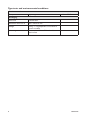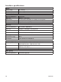
1
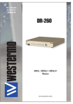
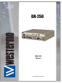
DR-250
WARNING
DSL2/2+
Router
www.westermo.com
© Westermo Teleindustri AB
User Guide
6622-2211
Legal information
The contents of this document are provided “as is”. Except as required by applicable
law, no warranties of any kind, either express or implied, including, but not limited to,
the implied warranties of merchantability and fitness for a particular purpose, are made
in relation to the accuracy and reliability or contents of this document. Westermo
reserves the right to revise this document or withdraw it at any time without prior
notice.
Under no circumstances shall Westermo be responsible for any loss of data or income
or any special, incidental, and consequential or indirect damages howsoever caused.
More information about Westermo can be found at the following Internet address:
http://www.westermo.com
2
6622-2211
Safety
!
Before using this unit:
Read this manual completely and gather all information on the unit. Make sure
that you understand it fully. Check that your application does not exceed the safe
operating specifications for this unit.
Hazardous voltages may occur within this unit when connected to a power supply.
Prevent access to hazardous voltages by disconnecting the unit from its power
supply.
Prevent damage to internal electronics from electrostatic discharges (ESD) by
discharging your body to a grounding point (e.g. use of wrist strap).
!
Before installation:
This unit should only be installed by qualified personnel.
This unit should be built-in to an apparatus cabinet, or similar, where access is
restricted to service personnel only.
The power supply wiring must be sufficiently fused, and if necessary it must be
possible to disconnect manually from the power supply. Ensure compliance to
national installation regulations.
This unit uses convection cooling. To avoid obstructing the airflow around the unit,
follow the spacing recommendations (see Installation section).
Care recommendations
Follow the care recommendations below to maintain full operation of unit and to fulfil
the warranty obligations.
This unit must not be operated with covers or lids removed.
Do not attempt to disassemble the unit. There are no user serviceable parts inside.
Do not drop, knock or shake the unit, rough handling beyond the specification may cause
damage to internal circuit boards.
Do not use harsh chemicals, cleaning solvents or strong detergents to clean the unit.
Do not paint the unit. Paint can clog the unit and prevent proper operation.
Do not expose the unit to any kind of liquids (rain, beverages, etc). The unit is not
waterproof.-Keep the unit within the specified humidity levels.
Do not use or store the unit in dusty, dirty areas, connectors as well as other mechanical
part may be damaged.
If the unit is not working properly, contact the place of purchase, nearest Westermo
distributor office or Westermo Tech support.
GSM specific safety
Please read and follow the guidelines listed below. The precautions must be observed
during all phases of the operation. Breaking these rules may be dangerous, illegal or affect
performance of the unit and/or invalidate the unit’s approval and/or warranty.
6622-2211
3
General
Remember to follow any special regulations and warnings in force in any area and never
use the unit whenever it’s forbidden to use it. Do not use the unit when it may cause
interference or danger. A wireless device exposed to interference above specified limits
could result in deteriorated performance.
Hospitals or other Medical environment
Do not use the unit in a medical environment such as health care facilities. Follow any
regulations or rules that instruct you to not use the unit.
Pacemakers
The Health Industry Manufacturers Association recommends that a minimum separation
of six (6”) inches be maintained between cellular wireless equipment and a pacemaker
to avoid potential interference with the pacemaker. These recommendations are consistent with the independent research by and recommendations of-Wireless Technology
Research.
Persons with pacemakers:
… Should ALWAYS keep the the unit and its antenna more than six inches from their
pacemaker when the unit is turned ON.
… If you have any reason to suspect that interference is taking place, turn your wireless
equipment OFF immediately.
Hearing Aids
Some digital wireless equipment may interfere with some hearing aids. In the event of
such interference, you may want to consult your service provider [or call the customer
service line to discuss alternatives.]
Other Medical Devices
If you use any other personal medical device, consult the manufacturer of your device to
determine if they are adequately shielded from external RF energy.-Your physician may be
able to assist you in obtaining this information.
Turn the wireless equipment OFF in health care facilities when any regulations posted in
these areas instruct you to do so. Hospitals or health care facilities may be using equipment that could be sensitive to external RF energy.
Aircraft
Do not use the unit in an aircraft. The use of a wireless unit in an aircraft may be dangerous to the operation of the aircraft, disrupt the wireless network, and may be illegal.
Failure to observe these instructions may lead to suspension or denial of cellular services
to the offender, legal action, or both.
Vehicle
If the unit is incorrectly installed in a vehicular environment, the operation of the unit
could interfere with the vehicle electronics. Faulty installation and/or operation can constitute a safety hazard.
4
6622-2211
For Vehicles equipped with an airbag
An air bag inflates with great force. DO NOT place objects, including either installed or
portable wireless equipment, in the area over the air bag or in the air bag deployment
area. If in-vehicle wireless equipment is improperly installed and the air bag inflates, serious injury could result.
Blasting areas
Do not use the unit where blasting is in progress or in “blasting areas”.
Observe restrictions and follow any regulation or rules.
Explosive atmospheres
Do not use the unit in any area with a potentially explosive atmosphere.
Potentially explosive areas are often, but not always, clearly marked.
They include fuelling areas such as petrol stations, below decks on boats, fuel or chemical
transfer or storage facilities, and areas where the air contains chemicals or particles, such
as grain, dust, or metal powder.
RF energy
The MR-200 is a low power radio transmitter and receiver. When it is ON, it receives
and also sends out radio frequency (RF) signals.
Most modern electronic equipment is shielded from RF signals. However, certain electronic equipment may not be shielded against the RF signals from the wireless unit. All
radio-transmitting devices send signals, which may cause interference in different electronic devices. To avoid interference, place the units antenna a sufficiently long distance
from other electronics.
Critical applications
Cellular units operate using radio signals and cellular networks cannot be guaranteed to
connect in all conditions. Therefore you should never rely solely on a wireless device for
essential communications, for example medical emergencies.
Backup copies
Remember to make backup copies of all important data, for example PIN/PUK codes,
contents of SIM card etc.
Antenna care
Use only the supplied or an approved replacement antenna. Unauthorized antennas,
modifications, or attachments could damage the unit and may violate current regulations.
Do not touch the antenna unnecessarily when the unit is in use. Contact with the antenna affects call quality and may cause the unit to operate at a higher power level than
otherwise needed.
Maintenance
No maintenance is required, as long as the unit is used as intended within the specified
conditions.
6622-2211
5
Agency approvals and standards compliance
6
Type
Approval / Compliance
EMC
EN301489-07: v1.2.1 (2002-08)
EN55022 1998
EN55024: 1998+A1:2001
Safety
IEC60950-1: 2005 Second Edition
EN60950-1:2006
RF spectrum
EN301511: v9.0.2
6622-2211
Declaration of Conformity
Westermo Teleindustri AB
Declaration of conformity
The manufacturer
Westermo Teleindustri AB
SE-640 40 Stora Sundby, Sweden
Herewith declares that the product(s)
Type of product
Model
Art no
ADSL 2/ 2+ Router
DR-250
3622-0010
is in conformity with the following EC directive(s).
No
Short name
1999/5/EC
radio and telecommunications terminal equipment (R&TTE)
References of standards applied for this EC declaration of conformity.
No
Title
Issue
EN 60950-1
EN 61000-3-2
Information technology equipment — Safety
Electromagnetic compatibility (EMC): - Limits for
harmonic current emissions
Electromagnetic compatibility (EMC) - Limitation of
voltage changes, voltage fluctuations and flicker in
public low-voltage supply systems.
Information technology equipment - Radio
disturbance characteristics
Information technology equipment - Immunity
characteristics
2006
2006
EN 61000-3-3
EN 55022
EN 55024
1995
+ A1:2001
+ A2:2005
2006
+ A1:2007
1998
+ A1:2001
+ A2:2003
EN 301 489-7 V1.3.1 Electromagnetic compatibility and Radio spectrum
Matters (ERM); ElectroMagnetic Compatibility
(EMC) standard for radio equipment and services
EN 301 511 V9.0.2
Global System for Mobile communications (GSM);
Harmonized EN for mobile stations in the GSM 900
and GSM 1800 bands
The last two digits of the year in which the CE marking was affixed:
10
Pierre Öberg
R&D Manager
3rd May 2010
Postadress/Postal address
Tel.
Telefax
Postgiro
Bankgiro
Org.nr/
Corp. identity number
Registered office
S-640 40 Stora Sundby
Sweden
016-428000
Int+46 16428000
016-428001
Int+46 16428001
52 72 79-4
5671-5550
556361-2604
Eskilstuna
6622-2211
7
Type tests and environmental conditions
Environmental
Temperature
Operating
–20 to +55°C
Packaging
8
Enclosure
Pressed steel
Dimension W x H x D
236 x 146 x 29 mm
Weight
0.8 kg – 1.1 kg dependant on model and
options installed
Mounting
Horizontal on 35 mm DIN-rail or flat on
level surface
6622-2211
Description
The DR-250 Is based on the very latest ADSL2/2+ platform, supporting the fastest broadband speeds available. ADSL2 offers considerable performance benefits over standard
ADSL, including improved range and data rate.
The DR-250 has an integral four port Ethernet switch and a 25 pin RS-232 serial interface for local connectivity. Devices that support serial protocols such as Modbus RTU,
DF1, DNP3, IEC870 etc can be easily connected to the DR-250 via the serial port.
The Ethernet interfaces support Multicasting (IGMP), VLAN, SNMP, SNTP, FTP, as well as
all the standard TCP, UDP and DHCP protocols. The inbuilt RS-232 port can be used to
connect legacy serial based equipment such as PLC’s, RTU’s or IED’s. Alternatively the
internal serial port can be used as a backup connection to the remote site when used in
conjunction with a suitable Westermo Modem.
The DR-250 router has an integrated stateful inspection firewall and can support
20 IPSEC VPN (Virtual Private Network) terminations which can be secured using
standard DES, 3DES, AES encryption and MD5 or SHA1 key exchange protocols.
These features ensure that the remote sites can use the latest security technology to
resist denial of service and hacking attacks. The VPN’s can be used as a way of increasing
security and to create secure tunnels, running between sites. The VPN’s can be used to
interconnect sites effectively replacing the requirement for dedicated leased lines. A VPN
tunnel can be established between any of the DR or MR series routers. Alternatively
VPN’s can be created between the DR-250 and a third party router. An optional license
for 50 or 100 VPN terminations is also available (up to a maximum of 200).
The DR-250 can also be used for remote sites access, allowing the user to browse WEB
pages, monitor / edit PLCs or access any device connected to the LAN. The DR-250 will
allow devices on the LAN to send emails or connect to FTP servers.
Multiple routers can be used on the same LAN to provide redundancy. The routers use
VRRP (Virtual Redundant Router Protocol) to allow a seamless changeover between primary and backup routers. For complex mesh network applications the DR-250 supports
OSPF, BGP and RIP2.
The DR-250 can be supplied with a combination of UMTS 3G/HSDPA wireless card, and
or PSTN/ISDN to backup the primary ADSL should there be an interruption in service.
The wide temperature range, 10 – 28 VDC supply and DIN rail mounting ensure that the
DR-250 can be used in industrial applications without the need for modification or consideration of the environmental conditions.
Features:
… ADSL / ADSL2 / ADSL2+ Compatibility
… Four port switch
… Integrated RS-232 terminal server port
… SNMP Management protocol
… Firewall
… IPsec VPN support (20 tunnels)
… VRRP+,BGP, OSPF, RIP2, GRE, L2TP
routing protocols
6622-2211
…
…
…
…
DIN Rail, wall or shelf mounted
–20˚C to +55˚C
10 – 28 VDC supply
DES • 3DES • AES • SSL • SSH
(standard)
9
Interface specifications
Power
Rated voltage
Rated current
Rated frequency
10 – 28 VDC
1500 mA @ 12 VDC
DC
RS-232
Electrical specification
Data rate
Data format
Transmission range
Connection
RS-232 V.24
300 bit/s – 115.2 kbit/s
7 or 8 data bits, Odd, even or no parity, 1 or 2 stop bits
2m
25-pin D-sub female (DCE)
Ethernet
Electrical specification
IEEE std 802.3. 2000 Edition
Data rate
10 Mbit/s or 100 Mbit/s, auto-negotiated
Protocol
UDP, TCP, ICMP, HTTP and ARP
Duplex
Full- or half duplex, auto-negotiated
Circuit type
TNV-1
Transmission range
100 m
Connection
RJ-45 shielded, auto MDI/MDI-X
Antenna (option)
Frequency bands
Data rate
Connection
GSM1800 TX 1710 – 1785 and RX 1805 – 1880 MHz
UMTS2100 TX 1920 – 1980 RX 2110 - 2170
CSD: up to 14.4 kbit/s
GPRS: up to 85.6 kbit/s
SMA female, impedance: 50 ohm
SIM (option)
Electrical specification
10
3 volts SIM supported
6622-2211
Connections
SIM Card Sockets
The two sockets at the left side of the front panel are for the GSM SIM card(s)
that you will receive from your service providers. Details of how to insert these
correctly are given on page 13.
USB Host Connectors*
LED Indicators
(for details
see next page)
Antenna
interface
RS-232
interface**
Ethernet interface
Antenna
interface
Ethernet interface
Power interface cord
* The USB host connectors may be used
to connect compatible USB 2.0 client
devices such as memory sticks, serial
adapters, etc. Note that the total current available to power USB devices is
collectively 0.5A (i.e. for both ports).
Cable
Description
Black
– VDC
Red
+ VDC
** RS-232 D-sub
25-position
No. 2
No. 3
No. 4
No. 5
No. 6
No. 7
No. 8
No. 15
No. 17
No. 20
No. 24
6622-2211
Direction
In
Out
In
Out
Out
–
Out
In
Out
In
In
Description
Transmit Data (TD)
Receive Data (RD)
Request To Send (RTS )
Clear To Send (CTS)
Data Set Ready (DSR)
Signal ground (SG)
Data Carrier Detect (DCD) )
Transmitter Clock (TxC)
Receiver Clock (RxC)
Data Terminal Ready (DTR)
External Transmitter Clock (ETC)
11
LED Indicators
LED
PWR
LAN
0, 1, 2, 3
DTE
DSL
W-WAN
Signal
ISDN
PSTN
Status
ON
OFF
ON
OFF
Flash
ON
OFF
Description
In service
Out of service
Network connection on LAN port
No connection on LAN port
Transmit or recive data on LAN port
Terminal connected to the serial port and the DTR signal is on
No connection on serial port Data is transmitted or received on
the serial port
Flash
Data is transmitted or received on the serial port
ON RED
No DSL is detected
FLASH RED
DSL training
ON GREEN
DSL active
FLASH GREEN
Data being transferred
NET ON
A wireless network has been detected
OFF
No wireless network has been detected
SIM ON
A valid SIM card is installed in the unit
OFF
No valid SIM card is installed in the unit
DAT Flash
Data is being transferred over the wireless network
OFF
No data is being transferred over the wireless network
The three indicators labelled SIGNAL illuminate to indicate the GSM signal strength
as follows:
None
< -113 dBm (effectively no signal)
illuminated
1 LED
>= -112 dBm and <= –87 dBm (weak)
illuminated
2 LED’s
>= -86 dBm and <= –71 dBm (medium)
illuminated
3 LED’s
>= -70 dBm and <= –51 dBm (strong)
illuminated
D ON
Connected to ISDN network and D-channel active
B1 ON
ISDN B-channel 1 active
FLASH
Data being transferred
2 ON
ISDN B-channel 2 active
FLASH
Data being transferred
OH ON
Modem off-hook
CD ON
Connected to a remote modem
DAT FLASH
Data being transfered
Reset switch
This is located on the underside of the unit near the front. Pressing the switch gently with the tip of
a pen or other suitable implement will generate a hardware reset.
Refer to page 15 (restoring factory defaults)
It is important to allow the DR-250 to complete the restore procedure. DO NOT press the reset
button again or power cycle the unit for at least 2 minutes.
12
6622-2211
Installation
Mounting / Removal
The router should be positioned on a smooth, level surface making sure that there is
adequate ventilation. Do not expose the router to extremes of heat or cold, strong
magnetic fields or liquids.
If the GSM option is fitted it is important to remember that these products are wireless
devices just like a mobile phone, so they will only operate reliably over the GSM network
if there is a good signal.
For many applications the stub aerial provided will be suitable but in some circumstances
it may be necessary to use a window-mounted or magnetically mounted aerial with an
extended cable to allow the aerial itself to be positioned to provide the best possible
signal reception. Westermo can supply a range of suitable aerials.
Step 1 – Installing the SIM card(s) (wireless option)
The router incorporates two separate SIM card holders so that if your application
demands it, you may install SIM cards for two different networks. This means that one
wireless service may be used as a back-up service in the event that the primary service
fails in some way. By default, SIM 1 is the default SIM used for access to the primary
network and SIM 2 is used for the back-up network.
Note: SIM 1 and SIM 2 cannot be used to access two networks simultaneously.
The SIM card(s) should be inserted into SIM cardholders on the right of the front panel
as illustrated below.
In both cases, the end of the SIM card with the chamfered corner should be inserted first.
For SIM 1 the contacts should be face down. For SIM 2 the contacts should be face up.
The easiest way to get started is to use SIM-cards without PIN-code. If the PIN-code is
activated it is possible to set this up in the settings for the router.
Step 2 – Fitting the wireless antenna (if applicable)
The router is supplied with a “stub” antenna suitable for with the model you have
ordered. Alternatively you may have ordered a different type of antenna separately. In
either case this should be screwed onto the SMA aerial connector on the rear of the
unit.
Step 3 – Connecting the LAN cable
Plug one end of one of the supplied 2 metre CAT5 STP cable into the RJ45 socket
labelled LAN 0. Plug the other end into the LAN socket on your PC or notebook.
6622-2211
13
Step 4 – Connecting the serial cable
For connection to a serial terminal device, connect the 25-way D plug on the serial cable
provided to the SERIAL connector on the rear of the unit. Connect the other end of the
cable (9-way D socket) to the terminal. If the serial connector on the terminal is not a
9-way D plug, you will need a suitable adapter.
Step 5 – Connecting the ADSL cable
Plug one end of the supplied cable, or a suitable alternative, into the RJ12 socket labelled
ADSL. Plug the other end into the ADSL line socket.
Step 6 – Connecting to the ISDN line (if applicable)
Plug one end the supplied CAT5 cable into the RJ45 socket labelled ISDN. Plug the other
end into the ISDN service outlet.
Step 7 – Connecting to the PSTN line (if applicable)
Plug one end of the supplied PSTN cable into the RJ45 socket labelled PSTN. Plug the
other end into the PSTN wall socket.
Step 8 – Connecting the power supply
Plug the jack plug on the mains adapter into the socket labelled 12VDC. When power is
first applied, the ON indicator will illuminate and the unit will initiate a series of diagnostic self-tests. During this process one or more of the other indicators, will flash to show
that the unit is busy. When the flashing stops, the unit is ready to use.
The unit is now ready to be configured.
14
6622-2211
Getting started
IP Address
The default IP address of the DR-250 when delivered is 192.168.0.99.
IP address configuration
The IP address is configurable by the Web tool and/or by using a terminal program.
Below is an description of how to configure the IP address by using a terminal program.
1. If the address is known, connect to the unit from a Web browser with the address of
the DR-250. If the address is unknown, connect the serial RS-232 interface to a terminal program with settings:
Data rate: 115.2 bit/s
Data bits: 8
Stop bits: 1
Parity: None
Flow control: None
2. Use any terminal-program to setup the IP-address, gateway and subnetmask.
Eth 0 ipaddr xxx.xxx.xxx.xxx (set up IP-address)
Eth 0 gateway yyy.yyy.yyy.yyy (set up Gateway)
Eth 0 mask zzz.zzz.zzz.zzz (set up subnetmask)
Eth 0 status (check settings)
Config 0 save (save configuration)
3. The unit is now ready for a complete configuration by the Web tool. Address DR-250
in a browser with the configured IP address. Note that the used computer have to be
on the same network as DR-250.
Username and Password for configuration
The DR-250 is username and password protected. These are used when connecting with
Web browser during configuration and with Telnet for diagnostics.
Default username: username
Default password: password
Restore Factory default settings
Note! This will clear your customized settings.
The factory default settings can be restored using the reset switch on the bottom of the
unit. Pressing (~15 sec) the switch gently with the tip of a pen or other suitable implement will generate a hardware reset.
Note! If the default address of the unit is valid on the connected network it is possible
to access the unit directly from a browser.
It is important to allow the DR-250 to complete the restore procedure. DO NOT press
the reset button again or power cycle the unit for at least 2 minutes.
6622-2211
15
Configuration by Web Tool
The DR-250 includes an easy-to-use Web configuration tool. The Web tool is very
intuitive and includes useful help information for the configurable parameters.
Connect and login to the DR-250 on the default IP address and with default username
and password combination (or your customized if configured) using a standard Web
browser.
Basic ADSL setup
The following must be done to get basic ADSL connectivity. There are two different ways
that are used to get a ADSL connection. This depends on what your ADSL provider uses.
PPP over Ethernet or PPP over ATM (PPPoE, PPPoA)
Username and password is supplied by your ADSL provider.
ADSL Interface
Choose the correct encapsulation PPPoE or PPPoA
PPP Account
Username: Supplied by your ADSL operator
Password: Supplied by your ADSL operator
Press Save then press OK
Press Reboot then press Reboot
After the reboot the Router will connect over ADSL and the LED DSL should flash
green.
Bridged Ethernet
ADSL Interface
Set Encapsulation method to Bridged Ethernet VC-Mux or Bridged Ethernet LLC.
(Check service provide details for correct setting)
Set VPI and VCI to match the values supplied by the ADSL service provide.
• ETH4 Bridged ADSL
Set DHCP client to Enabled
Set NAT Mode to NAT
• Default route 0
Set Interface to Ethernet
Set Interface #: to 4
The Source Mask (255.255.255.0) should be removed
Press Save then press OK
Press Reboot then press Reboot
After the reboot the Router will connect over ADSL and the LED DSL should flash
green.
16
6622-2211
Basic Ethernet configuration
Basic IP Address
• Static IP
To change the default IP-address 192.168.0.99 and subnet mask to something else.
Basic IP Address
• DHCP
Minimum assigned IP address: eg 192.168.0.2
IP address range:
eg 20 (highest address will then be 192.168.0.22)
DNS server address:
Address of router (192.168.0.99 default setting)
Gateway address:
Address of router (192.168.0.99 default setting)
Mask:
255.255.255.0
All settings above must be saved to one of the two profiles and then restarted.
After that change the IP-address of the client computer to accept an IP-address from the
DHCP server in the DR-250 and verify that the computer receive a correct IP-address.
Time
To setup the internal clock of the router to get correct time in logs etc.
6622-2211
17
Westermo Teleindustri AB • SE-640 40 Stora Sundby, Sweden
Phone +46 16 42 80 00 Fax +46 16 42 80 01
E-mail: [email protected]
Westermo Web site: www.westermo.com
Westermo Data Communications AB
Svalgången 1
SE-724 81 Västerås
Phone: +46 (0)21 548 08 00 • Fax: +46 (0)21 35 18 50
[email protected]
Westermo Data Communications Ltd
Talisman Business Centre • Duncan Road
Park Gate, Southampton • SO31 7GA
Phone: +44(0)1489 580-585 • Fax.:+44(0)1489 580586
E-Mail: [email protected]
Westermo Data Communications S.A.R.L.
9 Chemin de Chilly 91160 CHAMPLAN
Tél : +33 1 69 10 21 00 • Fax : +33 1 69 10 21 01
E-mail : [email protected]
Westermo Data Communications Pte Ltd
2 Soon Wing Road #08-05
Soon Wing Industrial Building
Singapore 347893
Phone +65 6743 9801 • Fax +65 6745 0670
E-Mail: [email protected]
Westermo Data Communications GmbH
Goethestraße 67, 68753 Waghäusel
Tel.: +49(0)7254-95400-0 • Fax.:+49(0)7254-95400-9
E-Mail: [email protected]
Westermo Teleindustri AB have distributors in several countries, contact us for further information.
REV.B 6622-2211 2010.05 Westermo Teleindustri AB, Sweden
Subsidiaries