1
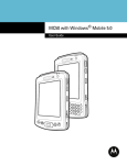
MC50 with Windows® Mobile 5.0
Integrator Guide
MC50 with Windows® Mobile 5.0
Integrator Guide
72E-89351-01
Revision A
May 2007
ii
MC50 with Windows® Mobile 5.0 Integrator Guide
© 2007 by Motorola, Inc. All rights reserved.
No part of this publication may be reproduced or used in any form, or by any electrical or mechanical means,
without permission in writing from Motorola. This includes electronic or mechanical means, such as
photocopying, recording, or information storage and retrieval systems. The material in this manual is subject to
change without notice.
The software is provided strictly on an “as is” basis. All software, including firmware, furnished to the user is on
a licensed basis. Motorola grants to the user a non-transferable and non-exclusive license to use each
software or firmware program delivered hereunder (licensed program). Except as noted below, such license
may not be assigned, sublicensed, or otherwise transferred by the user without prior written consent of
Motorola. No right to copy a licensed program in whole or in part is granted, except as permitted under
copyright law. The user shall not modify, merge, or incorporate any form or portion of a licensed program with
other program material, create a derivative work from a licensed program, or use a licensed program in a
network without written permission from Motorola. The user agrees to maintain Motorola’s copyright notice on
the licensed programs delivered hereunder, and to include the same on any authorized copies it makes, in
whole or in part. The user agrees not to decompile, disassemble, decode, or reverse engineer any licensed
program delivered to the user or any portion thereof.
Motorola reserves the right to make changes to any software or product to improve reliability, function, or
design.
Motorola does not assume any product liability arising out of, or in connection with, the application or use of
any product, circuit, or application described herein.
No license is granted, either expressly or by implication, estoppel, or otherwise under any Motorola, Inc.,
intellectual property rights. An implied license only exists for equipment, circuits, and subsystems contained in
Motorola products.
MOTOROLA and the Stylized M Logo and Symbol and the Symbol logo are registered in the US Patent &
Trademark Office. Bluetooth is a registered trademark of Bluetooth SIG. Microsoft, Windows and ActiveSync
are either registered trademarks or trademarks of Microsoft Corporation. All other product or service names
are the property of their respective owners.
Motorola, Inc.
One Motorola Plaza
Holtsville, New York 11742-1300
http://www.symbol.com
iii
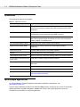
Revision History
Changes to the original manual are listed below:
Change
-01 Rev A
Date
5/2007
Description
Initial Release.
iv
MC50 with Windows® Mobile 5.0 Integrator Guide
Table of Contents
Chapter 1
About This Guide
Introduction .................................................................................................................... xi
Documentation Set .................................................................................................. xi
Configurations................................................................................................................ xii
Software Versions.................................................................................................... xiii
Chapter Descriptions ..................................................................................................... xiv
Related Documents and Software ................................................................................. xv
Service Information ........................................................................................................ xv
Chapter 1: Getting Started
Introduction ................................................................................................................... 1-1
Unpacking the Mobile Computer ................................................................................... 1-1
Accessories ................................................................................................................... 1-2
MC50 Sample Applications ........................................................................................... 1-2
Getting Started .............................................................................................................. 1-3
Installing and Removing the Main Battery .................................................................... 1-3
Installing the Main Battery ....................................................................................... 1-3
Removing the Main Battery ..................................................................................... 1-4
Charging the Battery ..................................................................................................... 1-4
Charging the Main Battery and Memory Backup Battery ........................................ 1-4
Calibrating the Battery ............................................................................................ 1-5
Charging Spare Batteries ........................................................................................ 1-5
Resetting the Mobile Computer .................................................................................... 1-6
Performing a Warm Boot ........................................................................................ 1-6
Performing a Cold Boot ........................................................................................... 1-6
Performing a Clean Boot ......................................................................................... 1-6
Installing the Windows Mobile 5.0 Operating System ................................................... 1-6
Locking the Keypad ...................................................................................................... 1-8
Chapter 2: Accessories
Introduction ................................................................................................................... 2-1
Cradles .................................................................................................................... 2-1
Miscellaneous ......................................................................................................... 2-1
Snap-on Modules .................................................................................................... 2-1
Headset ......................................................................................................................... 2-2
Multi Media Card (MMC) / Secure Device (SD) Card ................................................... 2-3
vi
MC50 with Windows® Mobile 5.0 Integrator Guide
Single Slot USB Cradle .................................................................................................
Setup .......................................................................................................................
Charging the Mobile Computer Battery ...................................................................
Charging the Spare Battery ....................................................................................
Battery Charging Indicators ....................................................................................
Four Slot USB Cradle ...................................................................................................
Setup .......................................................................................................................
UConnect ................................................................................................................
Charging ................................................................................................................
Battery Charging Indicators ....................................................................................
Four Slot Ethernet Cradle .............................................................................................
Setup .......................................................................................................................
Daisychaining Cradles ............................................................................................
Ethernet Cradle Drivers ..........................................................................................
Charging ................................................................................................................
Battery Charging Indicators ....................................................................................
Four Slot Spare Battery Charger ..................................................................................
Spare Battery Charging ..........................................................................................
Battery Charging Indicators ....................................................................................
Magnetic Stripe Reader (MSR) .....................................................................................
Attaching and Removing .........................................................................................
Using the MSR .......................................................................................................
Cable Adapter Module ..................................................................................................
Attaching and Removing .........................................................................................
Battery Charging .....................................................................................................
USB Connection .....................................................................................................
Universal Battery Charger (UBC) Adapter ....................................................................
Setup .......................................................................................................................
Battery Insertion and Removal ................................................................................
Battery Charging Indicators ....................................................................................
2-4
2-4
2-5
2-5
2-5
2-7
2-8
2-8
2-12
2-12
2-13
2-13
2-14
2-15
2-17
2-17
2-18
2-18
2-19
2-20
2-20
2-20
2-22
2-22
2-23
2-24
2-25
2-25
2-25
2-26
Chapter 3: ActiveSync
Introduction ...................................................................................................................
Installing ActiveSync .....................................................................................................
Mobile Computer Setup ................................................................................................
Setting Up an ActiveSync Connection on the Host Computer ......................................
Synchronization with a Windows Mobile 5.0 Device ...............................................
3-1
3-1
3-2
3-3
3-4
Chapter 4: Application Deployment
Introduction ...................................................................................................................
Security .........................................................................................................................
Application Security ................................................................................................
Digital Signatures ....................................................................................................
Device Management Security .................................................................................
Remote API Security ...............................................................................................
Packaging .....................................................................................................................
Deployment ...................................................................................................................
4-1
4-1
4-1
4-1
4-3
4-4
4-4
4-4
Table of Contents
Installation Using ActiveSync .................................................................................. 4-4
Installation Using Storage Card .............................................................................. 4-5
Installation Using AirBEAM ..................................................................................... 4-5
Image Update ......................................................................................................... 4-5
Creating a Splash Screen ....................................................................................... 4-6
XML Provisioning .......................................................................................................... 4-7
Creating an XML Provisioning File .......................................................................... 4-7
XML Provisioning vs. RegMerge and CopyFiles ..................................................... 4-7
Storage ......................................................................................................................... 4-9
Random Access Memory ........................................................................................ 4-9
Persistent Storage .................................................................................................. 4-10
Application Folder ................................................................................................... 4-10
System Configuration Manager .................................................................................... 4-11
File Types ............................................................................................................... 4-11
User Interface ......................................................................................................... 4-11
File Deployment ...................................................................................................... 4-13
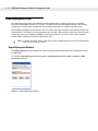
Rapid Deployment Client .............................................................................................. 4-14
Rapid Deployment Window ..................................................................................... 4-14
Scanning RD Bar Codes ......................................................................................... 4-15
AirBEAM Smart ............................................................................................................. 4-17
AirBEAM Package Builder ...................................................................................... 4-17
AirBEAM Smart Client ............................................................................................. 4-18
Synchronizing with the Server ................................................................................ 4-27
AirBEAM Staging .................................................................................................... 4-27
Symbol Mobility Developer Kits .................................................................................... 4-28
Chapter 5: Wireless Applications
Introduction ................................................................................................................... 5-1
Signal Strength Icon ...................................................................................................... 5-2
Turning the WLAN Radio On and Off ........................................................................... 5-3
Find WLANs Application ............................................................................................... 5-4
Profile Editor Wizard ..................................................................................................... 5-5
Profile ID ................................................................................................................. 5-5
Operating Mode ...................................................................................................... 5-6
Ad-Hoc .................................................................................................................... 5-7
Authentication ......................................................................................................... 5-7
Tunneled Authentication ......................................................................................... 5-8
User Certificate Selection ....................................................................................... 5-10
Server Certificate Selection .................................................................................... 5-11
Credential Cache Options ....................................................................................... 5-11
User Name .............................................................................................................. 5-13
Password ................................................................................................................ 5-14
Advanced Identity ................................................................................................... 5-14
Encryption ............................................................................................................... 5-15
IP Address Entry ..................................................................................................... 5-17
Transmit Power ....................................................................................................... 5-19
Battery Usage ......................................................................................................... 5-20
Manage Profiles Application ................................................................................... 5-21
vii
viii
MC50 with Windows® Mobile 5.0 Integrator Guide
Wireless Status Application ..........................................................................................
Signal Strength Window ..........................................................................................
Current Profile Window ...........................................................................................
IPv4 Status Window ................................................................................................
Wireless Log Window .............................................................................................
Versions Window ....................................................................................................
Wireless Diagnostics Application ..................................................................................
ICMP Ping Window .................................................................................................
Trace Route Window ..............................................................................................
Known APs Window ................................................................................................
Options .........................................................................................................................
Operating Mode Filtering ........................................................................................
Band Selection ........................................................................................................
System Options .......................................................................................................
Change Password ...................................................................................................
Export ......................................................................................................................
Persistence ...................................................................................................................
Log On/Off Application ..................................................................................................
User Already Logged In ..........................................................................................
No User Logged In ..................................................................................................
Registry Settings ...........................................................................................................
5-24
5-25
5-27
5-28
5-29
5-30
5-31
5-32
5-33
5-33
5-34
5-35
5-35
5-36
5-36
5-37
5-38
5-39
5-39
5-39
5-41
Chapter 6: Maintenance & Troubleshooting
Introduction ...................................................................................................................
Maintaining the Mobile Computer ...........................................................................
Troubleshooting ............................................................................................................
Mobile Computer .....................................................................................................
Four Slot Spare Battery Charger ............................................................................
Single Slot USB Cradle ...........................................................................................
Four Slot USB and Ethernet Cradles ......................................................................
Cable Adapter Module ............................................................................................
Magnetic Stripe Reader ..........................................................................................
6-1
6-1
6-2
6-2
6-4
6-5
6-6
6-7
6-7
Appendix A: Technical Specifications
Technical Specifications ...............................................................................................
MC50 Accessory Specifications ..............................................................................
COM Port Definitions ....................................................................................................
Pin-Outs ........................................................................................................................
A-1
A-5
A-8
A-9
Appendix B: Keypad Maps
Introduction ................................................................................................................... B-1
Example .................................................................................................................. B-1
Keypads ........................................................................................................................ B-2
Glossary
Table of Contents
Index
Tell Us What You Think...
ix
x
MC50 with Windows® Mobile 5.0 Integrator Guide
About This Guide
About This Guide
Introduction
This Integrator Guide provides information about setting up and configuring MC50 with Windows Mobile 5.0
mobile computers and accessories.
NOTE
Screens and windows pictured in this guide are samples and can differ from actual screens.
Documentation Set
The documentation for the MC50 is divided into guides that provide information for specific user needs.
•
Microsoft® Applications User Guide for Symbol Devices - describes how to use Microsoft-developed
applications.
•
Symbol Application Guide - describes how to use Symbol-developed applications.
•
MC50 User Guide - describes how to use the MC50 mobile computer.
•
MC50 Integrator Guide - describes how to set up MC50 product accessories and how to install
software.
•
API Help File - provides API information for writing applications for the MC50.
xii
MC50 with Windows® Mobile 5.0 Integrator Guide
Configurations
Depending on device configuration, the MC50 includes the following features:
•
Operating System: Microsoft Windows Mobile 5.0
•
Memory Configuration: 64 MB ROM/64 MB RAM
•
Display: 3.5” QVGA transflective color touchscreen
•
Keypads: Navigation (PDA-style) or QWERTY
•
Data Capture: 1-dimensional bar code scanning via linear CMOS, 1-dimensional and 2-dimensional bar
code imaging, or image capture via camera
•
Radio: 802.11b wireless LAN (WLAN).
About This Guide
xiii
Software Versions
This guide covers various software configurations and references are made to operating system or software
versions for:
•
Adaptation Kit Update (AKU) version
•
Fusion version.
AKU Version
To determine the Adaptation Kit Update (AKU) version:
Tap Start > Settings > System tab > About icon > Version tab.
This tab lists the operating system version and the build number. The last part of the build number represents
the AKU number. For example, Build 15704.3.5.0 indicates that the device is running AKU version 3.5.0.
Fusion Software
To determine the Fusion software version:
Tap Wireless Strength icon > Wireless Status > Versions.
xiv
MC50 with Windows® Mobile 5.0 Integrator Guide
Chapter Descriptions
Topics covered in this guide are as follows:
•
Chapter 1, Getting Started describes the accessories available for the mobile computer and how to set
up power connections and battery charging capabilities, where applicable.
•
Chapter 2, Accessories describes the accessories available for the MC50 and how to set up power
connections and battery charging capabilities, where applicable.
•
Chapter 3, ActiveSync provides instructions on installing ActiveSync and setting up a partnership
between the mobile computer and a host computer.
•
Chapter 4, Application Deployment describes new features in Windows Mobile 5.0 including new security
features, how to package applications, and procedures for deploying applications onto the mobile
computer.
•
Chapter 5, Wireless Applications describes how to configure the wireless connection.
•
Chapter 6, Maintenance & Troubleshooting, includes instructions on cleaning and storing the mobile
computer, and provides troubleshooting solutions for potential problems during mobile computer
operation.
•
Appendix A, Technical Specifications includes a table listing the technical specifications for the mobile
computer.
•
Appendix B, Keypad Maps contains keypad maps for keypad configurations.
Notational Conventions
The following conventions are used in this document:
•
“Mobile computer” refers to any Symbol hand-held computer.
•
Italics are used to highlight chapters and sections in this and related documents
•
Bold text is used to highlight the following:
• dialog box, window and screen names
• drop-down list and list box names
• check box and radio button names
• icons on a screen.
• key names on a keypad
• button names on a screen.
•
Bullets (•) indicate:
• action items
• lists of alternatives
• lists of required steps that are not necessarily sequential.
•
Sequential lists (e.g., those that describe step-by-step procedures) appear as numbered lists.
About This Guide
NOTE
xv
This symbol indicates something of special interest or importance to the reader. Failure to read the note
will not result in physical harm to the reader, equipment or data.
CAUTION
WARNING!
This symbol indicates that if this information is ignored, the possiblity of data or material damage may
occur.
This symbol indicates that if this information is ignored the possibility that serious personal
injury may occur.
Related Documents and Software
The following documents provide more information about the MC50 mobile computers.
•
MC50 Quick Start Poster, p/n 72-67793-xx
•
MC50 Regulatory Guide, p/n 72-67863-xx
•
MC50 User Guide, p/n 72E-68195-xx
•
Microsoft® Applications User Guide for Symbol Devices, p/n 72-68197-xx
•
Symbol Application Guide, p/n 72-65258-xx
•
Symbol Mobility Developer Kits (SMDKs), available at:http://support.symbol.com.
•
ActiveSync software, available at: http://www.microsoft.com.
For the latest version of this guide and all guides, go to: http://support.symbol.com.
Service Information
If you have a problem with your equipment, contact Motorola Enterprise Mobility Support for your region.
Contact information is available at: http://www.symbol.com/customersupport. If you purchased your Enterprise
Mobility business product from a Motorola business partner, contact that business partner for support.
Before contacting, have the model number and serial number at hand. If your problem cannot be solved by
Motorola Enterprise Mobility Support, you may need to return your equipment for servicing and will be given
specific directions.
Motorola is not responsible for any damages incurred during shipment if the approved shipping container is not
used. Shipping the units improperly can possibly void the warranty.
xvi
MC50 with Windows® Mobile 5.0 Integrator Guide
Chapter 1
Getting Started
Chapter 1
Chapter 1 Getting Started
Introduction
This chapter provides information about the mobile computer, accessories, charging the mobile computer, and
resetting the mobile computer.
Unpacking the Mobile Computer
Carefully remove all protective material from around the mobile computer and save the shipping container for
later storage and shipping. Verify that the equipment listed below is included:
• mobile computer
• stylus, in the stylus silo
• hand strap
• soft case
• Regulatory Guide
• Quick Start Guide (poster).
Depending on the configuration ordered, the mobile computer package can also include:
• standard or extra capacity battery
• AC adaptor
• communication/charging cable
• power supply
• US line cord
• headset
• desktop cradle.
Inspect the equipment. If any equipment is missing or damaged, contact the Motorola Global Customer
Interaction Center immediately. See Service Information on page xv for contact information.
1-2
MC50 with Windows® Mobile 5.0 Integrator Guide
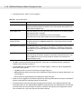
Accessories
The following accessories are available:
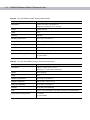
Table 1-1 MC50 Accessories
Accessory
Description
Single Slot USB Cradle
Charges the mobile computer main battery and a spare battery, and
synchronizes the mobile computer with a host computer through a USB
connection.
Four Slot USB Cradle
Charges up to four mobile computers, and synchronizes the mobile
computer with a host computer through a USB connection.
Four Slot Ethernet Cradle
Charges up to four mobile computers, synchronizes the mobile computer
with a host computer through an Ethernet connection, and networks the
mobile computer via an Ethernet hub.
Four Slot Spare Battery Charger
Charges up to four mobile computer spare batteries.
Magnetic Stripe Reader (MSR)
Snaps on to the mobile computer and adds magstripe reading
capabilities.
Rigid Carrying Case
Provides added protection for the mobile computer.
Headset
For audio playback in noisy environments.
Cable Adapter Module (CAM)
Snap-on required to connect the following cables to the mobile computer:
AC line cord (country-specific) and
power supply
Used with the CAM to charge the mobile computer.
Auto charge cable
Used with the CAM to charge the mobile computer using a vehicle’s
power port.
USB cable
Used with the CAM to add USB communication capabilities.
Universal Battery Charger Adapter
Adapts the UBC for use with MC50 batteries.
Software
Symbol Mobility Developer Kits (SMDKs), available at:
http://www.symbol.com/mc50.
MC50 Sample Applications
To download Mobile 5.0 sample applications that assist in application development, visit
http://support.symbol.com.
Copy the sample applications CAB file to the MC50’s Temp directory, and tap the file to install. To access the
sample applications, tap Start > Programs > Samples icon. Refer to the Symbol Application Guide, p/n
72-65258-xx for information on using the applications.
Getting Started
1-3
Getting Started
Before using the mobile computer for the first time:
• install the main battery
• charge the main battery and backup battery
• start the mobile computer
• configure the mobile computer.
Charge the main battery before or after it is installed. Use one of the spare battery chargers to charge the main
battery (out of the mobile computer), or one of the cradles to charge the main battery installed in the mobile
computer.
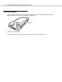
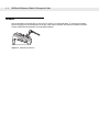
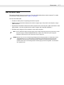
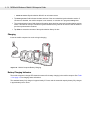
Installing and Removing the Main Battery
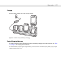
Installing the Main Battery
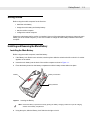
Before using the mobile computer, install the battery:
1.
If the Battery Lock Switch is not unlocked, use the stylus to slide the switch to the left to unlock it. A red dot
appears on the switch.
2.
Insert the main battery into the back of the mobile computer as show in Figure 1-1.
3.
Press the battery down into the battery compartment until the battery release slides into place.
Battery
Battery Lock Switch
Battery Release
Figure 1-1 Inserting the Battery
NOTE
4.
Ensure the battery is positioned correctly, placing the battery charging contacts on top of the charging
contacts in the battery compartment.
Using the stylus, slide the Battery Lock Switch to the right to lock it.
1-4
MC50 with Windows® Mobile 5.0 Integrator Guide
Removing the Main Battery
To remove the main battery:
1.
Press the power button to suspend the mobile computer.
2.
Using the stylus, slide the Battery Lock Switch to the left to unlock it. A red dot appears on the switch.
3.
Slide the battery release down, and pull the battery up and out of the mobile computer.
Charging the Battery
Charging the Main Battery and Memory Backup Battery
Before using the mobile computer for the first time, charge the main battery until the amber charge status LED
remains lit (see Table 1-2 on page 1-5 for charge status indications). To charge the mobile computer, use a
cradle or the CAM with a charging cable.
The mobile computer is equipped with a memory backup battery which automatically charges from the
fully-charged main battery. When using the mobile computer for the first time, the backup battery requires
approximately 24 hours to fully charge. This is also true any time the backup battery is discharged, which
occurs when the main battery is removed for several hours. The backup battery retains data in memory for at
least 30 minutes when the mobile computer's main battery is removed. When the mobile computer reaches a
very low battery state, the combination of main battery and backup battery retains data in memory for at least
72 hours.
NOTE
Do not remove the main battery within the first 15 hours of use. If the main battery is removed before the
backup battery is fully charged, data can be lost.
Use the following accessories to charge batteries:
• Cradles: The mobile computer and spare batteries slip into a cradle for battery charging. For detailed
cradle setup and charging procedures see:
• Single Slot USB Cradle on page 2-4.
• Four Slot Ethernet Cradle on page 2-13
• Four Slot Ethernet Cradle on page 2-13.
• Cable Adapter Module (CAM): The CAM snaps on to the mobile computer to provide charging capability,
when used with one of the accessory charging cables. For detailed setup and charging procedures see
Cable Adapter Module on page 2-22.
• Chargers: The mobile computer’s spare battery charging accessories are used to charge batteries that
are removed from the mobile computer. For detailed spare battery charging accessories setup and
charging procedures see:
• Single Slot USB Cradle on page 2-4
• Four Slot Spare Battery Charger on page 2-18
• Universal Battery Charger (UBC) Adapter on page 2-25.
Getting Started
1-5
To charge the main battery in the mobile computer using a cradle or the CAM with a charging cable:
1.
Ensure the accessory used to charge the main battery is connected to the appropriate power source (see
Chapter 2, Accessories for setup information).
2.
Insert the mobile computer into a cradle or attach the CAM.
3.
The mobile computer begins charging. The Charge LED is amber while charging, then turns green when
fully charged.
The standard battery fully charges in approximately 3.5 hours and the extended capacity battery fully charges
in approximately seven hours.
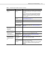
Table 1-2 Mobile Computer LED Charge Indicators
LED
Indication
Green
Main battery is fully charged.
Amber
Charging main battery.
Flashing Amber
Error in charging; check cable connections.
Calibrating the Battery
The MC50 battery requires periodic calibration to maintain an accurate calibration of the battery's gas gauge.
To calibrate the battery, deplete the battery completely from a full charge condition. Motorola recommends
performing this once a week.
Charging Spare Batteries
Use one of the following accessories to charge spare batteries:
• Single Slot USB Cradle
• Four Slot Spare Battery Charger
• UBC Adapter.
To charge a spare battery:
1.
Ensure the accessory used to charge the spare battery is connected to the appropriate power source (see
Chapter 2, Accessories for setup information).
2.
Insert the spare battery into the accessory’s spare battery charging slot with the charging contacts on the
battery aligned with the charging pins in the charging slot, and gently press down on the battery to ensure
proper contact.
The battery begins charging. The amber charge LED on the accessory lights to show the charge status.
See Chapter 2, Accessories for charging indications for the accessory.
In the single slot cradle, the standard battery fully charges in 3.5 hours and the extended capacity battery fully
charges in approximately seven hours. Using other accessories, the standard battery fully charges in 2.5 hours
and the extended capacity battery fully charges in approximately six hours.
1-6
MC50 with Windows® Mobile 5.0 Integrator Guide
Resetting the Mobile Computer
There are two reset functions, warm boot and cold boot. A warm boot restarts the mobile computer by closing
all running programs. A cold boot also restarts the mobile computer, and also resets the clock. Data saved in
flash memory or a memory card is not lost.
Perform a warm boot first. If the mobile computer still does not respond, perform a cold boot.
Performing a Warm Boot
Press the reset button on the back of the mobile computer with the stylus.
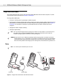
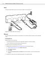
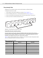
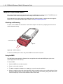
Performing a Cold Boot
Hold down the Power and right Scan/Action buttons, then press and release the reset button located below
the battery release on the back of the mobile computer. Release the Power and right Scan/Action buttons.
Power Button
Reset Button
Scan/Action Button
Figure 1-2 Boot Buttons
Performing a Clean Boot
CAUTION
Only an authorized system administrator should perform a clean boot.
You must connect the mobile computer to AC power during a clean boot. Removing AC power from
the mobile computer during a clean boot may render the mobile computer inoperable.
A clean boot resets the mobile computer to the factory default settings. All data in the Application folder is
retained. To perform a clean boot, download the Clean Boot Package from Support Central. Follow the
instructions included in the package to install and run the package on the mobile computer.
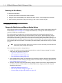
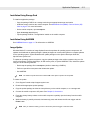
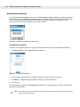
Installing the Windows Mobile 5.0 Operating System
To upgrade the Pocket PC 2003 operating system to the Mobile 5.0 operating system:
1.
Download the upgrade zip file, available for purchase, to a desktop computer.
2.
Cold boot the MC50. See Performing a Cold Boot on page 1-6.
Getting Started
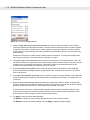
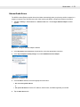
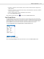
3.
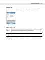
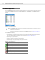
1-7
Tap Start > Settings > System tab > Memory icon > Main tab.
Figure 1-3 Memory Window - Main Tab
4.
Move the slider to to the left to allocate approximately 40 MB of memory for programs. Ensure the slider
does not move back to the right, which can occur if you allocate more than 40 MB for programs.
5.
Tap ok.
6.
Warm boot the MC50. See Performing a Warm Boot on page 1-6.
7.
Verify that the MC50 maintained the memory allocation set before the warm boot. If not, repeat steps 2
through 4.
8.
Extract all files from the zip archive and copy them to an SD card.
9.
Insert the SD card into the MC50. See Multi Media Card (MMC) / Secure Device (SD) Card on page 2-3 for
instructions.
10. Place the MC50 into a cradle with AC power applied.
11. Use File Explorer to navigate to the Storage Card folder. To open File Explorer, tap Start > Programs > File
Explorer.
12. Tap the mc50_update.lnk file to initiate the upgrade. The upgrade takes approximately 10 minutes.
CAUTION
Do not remove the mobile computer from the cradle or remove power during the upgrade.
1-8
MC50 with Windows® Mobile 5.0 Integrator Guide
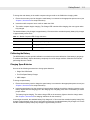
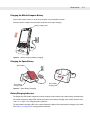
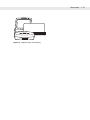
Locking the Keypad
Use the Keypad Lock switch to lock the keypad so that keys are not accidently pressed. Note that when
locked, the mobile computer does not respond to keypad input.
Keypad Lock
Figure 1-4 Function Buttons
Move this switch up to lock the keypad. Move the switch down to free the keypad for use.
Chapter 2
Accessories
Chapter 2
Chapter 2 Accessories
Introduction
MC50 accessories provide a variety of product support capabilities. Accessories include cradles, Magnetic
Stripe Reader (MSR) and Cable Adapter Module (CAM) snap-ons, four-slot spare battery charger, headset,
Multimedia Card (MMC), Secure Device (SD) card, and Universal Battery Charger (UBC) adapter.
Cradles
• Single Slot USB cradle charges the mobile computer main battery and a spare battery. It also
synchronizes the mobile computer with a host computer through a USB connection.
• Four Slot USB cradle charges the mobile computer main battery. It also synchronizes the mobile
computer with a host computer through a USB connection.
• Four Slot Ethernet cradle charges the mobile computer main battery and connects the mobile computer
with an Ethernet network.
Miscellaneous
• Four Slot Spare Battery Charger charges up to four mobile computer spare batteries.
• Headset can be used in noisy environments.
• Multimedia Card or Secure Digital (SD) Card provides secondary non-volatile storage.
• UBC adapter adapts the UBC for use with MC50 batteries.
Snap-on Modules
• MSR snaps on to the mobile computer and adds magstripe read capabilities.
• CAM snaps on to the mobile computer and connects cables to the mobile computer for battery charging
and synchronizing the mobile computer with a host computer through a USB connection.
The CAM uses the cables listed below:
• AC line cord (country-specific) and power supply, charges the mobile computer.
• Auto charge cable, charges the mobile computer using a vehicle’s cigarette lighter.
• USB cable, adds USB communication capabilities.
2-2
MC50 with Windows® Mobile 5.0 Integrator Guide
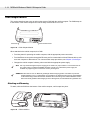
Headset
Use the headset to communicate via Voice-over-IP (VoIP) or for audio playback. To connect the headset,
remove the plug from the headset jack at the top of the mobile computer and insert the headset connector.
Contact a Motorola representative for compatible headsets.
Figure 2-5 Headset Connection
Accessories
2-3
Multi Media Card (MMC) / Secure Device (SD) Card
The MMC/SD card slot provides secondary non-volatile storage. The slot is located at the top of the mobile
computer (see Figure 2-5).
A variety of third-party cards can be used in the mobile computer for storage, Bluetooth connection,
Voice-over-IP, and other functions. Refer to the documentation provided with the card for more information,
and follow the manufacturer’s recommendations for use.
NOTE
SD cards are inter-operable with MMC cards; both can be used in MC50 mobile computers.
CAUTION
Follow proper ESD precautions to avoid damaging the MMC/SD. Proper ESD precautions include, but
are not limited to, working on an ESD mat and ensuring that the operator is properly grounded.
To insert the MMC/SD:
1.
Power off the mobile computer.
2.
Remove the card cover at the top of the mobile computer by removing the screw and lifting the cover out of
the slot.
3.
If a card is already installed, press the card in to release it, then remove it.
4.
Insert the new card with the card contacts aligning with the contacts in the MMC/SD housing, until you feel
a click.
Figure 2-6 MMC/SD Card Insertion
5.
Replace the housing cover and secure with the screw.
2-4
MC50 with Windows® Mobile 5.0 Integrator Guide
Single Slot USB Cradle
This section describes how to set up and use a Single Slot USB cradle with the mobile computer. For USB
communication setup procedures see Chapter 3, ActiveSync.
The Single Slot USB Cradle:
• Provides 5.4 VDC power for operating the mobile computer.
• Synchronizes information between the mobile computer and a host computer. (With customized or third
party software, it can also synchronize the mobile computer with corporate databases.) See Chapter 3,
ActiveSync for information on setting up a partnership between the mobile computer and a host
computer.
• Charges the mobile computer’s battery.
• Charges a spare battery.
NOTE
Use only a Motorola-approved power supply (p/n 50-14000-147) output rated 5.4 Vdc and minimum 3A.
The power supply is certified to EN60950 with SELV outputs. Use of alternative power supply will
invalidate any approval given to this device and may be dangerous.
HINWEIS Benutzen Sie nur eine von Motorola genehmigte Stromversorgung (Teilenr. 50-14000-147) mit einer
Ausgangsleistung von 5.4 V (Gleichstrom) und mindestens 3A. Die Stromversorgung ist nach EN60950
für die Verwendung in SELV-Stromkreisen zertifiziert. Bei Verwendung eines anderen Netzteils werden
alle für das Gerät gewährten Genehmigungen außer Kraft gesetzt, und der Betrieb kann gefährlich sein.
Setup
NOTE
The cradle requires a dedicated port on the host.
USB Port
Power Port
Power Supply
Figure 2-7 Single Slot Cradle Power and USB Connections
Accessories
2-5
Charging the Mobile Computer Battery
Connect the cradle to power, or to the host computer using the USB connection.
Insert the mobile computer into the mobile computer slot to begin charging.
Battery Charging LED
Figure 2-8 Mobile Computer Battery Charging
Charging the Spare Battery
Spare Battery
Spare Battery
Charging Well
Spare Battery
Charging LED
Figure 2-9 Spare Battery Charging
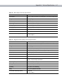
Battery Charging Indicators
The Single Slot USB Cradle charges the mobile computer’s main battery and a spare battery simultaneously.
The mobile computer’s charge LED indicates the status of the battery charging in the mobile computer. See
Table 1-2 on page 1-5 for charging status indications.
The spare battery charging LED on the cradle indicates the status of the spare battery charging in the cradle.
See Table 2-3 on page 2-6 for charging status indications.
2-6
MC50 with Windows® Mobile 5.0 Integrator Guide
The standard battery fully charges in approximately 3.5 hours and the extended capacity battery fully charges
in approximately seven hours.
Table 2-3
Spare Battery LED Charging Indicators
Spare Battery LED
(on cradle)
Indication
Off
No spare battery in slot; spare battery not placed correctly; cradle is not
powered.
Solid Amber
Spare battery is charging.
Flashing Amber
Error in charging; check placement of spare battery.
Solid Green
Spare battery is fully charged.
Accessories
2-7
Four Slot USB Cradle
This section describes how to set up and use a Four Slot USB cradle with the mobile computer. For cradle
communication setup procedures see, Chapter 3, ActiveSync.
The Four Slot USB cradle:
• Provides 12 VDC power for operating the mobile computer.
• Enables data communication between the mobile computer (up to four) and a host computer, using a
USB connection.
• Synchronizes information between the mobile computer and a host computer. (With customized or third
party software, it can also synchronize the mobile computer with corporate databases.)
• Simultaneously charges up to four batteries in the mobile computer.
NOTE
Use only a Motorola-approved power supply (p/n 50-14000-148) output rated 12 Vdc and minimum 3.33A.
The power supply is certified to EN60950 with SELV outputs. Use of alternative power supply will
invalidate any approval given to this device and may be dangerous.
HINWEIS Benutzen Sie nur eine von Motorola genehmigte Stromversorgung (Teilenr. 50-14000-148) mit einer
Ausgangsleistung von 12 V (Gleichstrom) und mindestens 3.33A. Die Stromversorgung ist nach
EN60950 für die Verwendung in SELV-Stromkreisen zertifiziert. Bei Verwendung eines anderen
Netzteils werden alle für das Gerät gewährten Genehmigungen außer Kraft gesetzt, und der Betrieb
kann gefährlich sein.
2-8
MC50 with Windows® Mobile 5.0 Integrator Guide
Setup
Connect the USB cradle to a power source and to a USB port on the host device.
Power Port
USB Port
Figure 2-10 Four Slot USB Cradle Connection
UConnect
UConnect software enables automatic synchronization of every mobile computer inserted in the Four-Slot USB
cradle.
Installing UConnect
Install UConnect in one of two ways:
• Download individual UConnect files to the Application partition of the mobile computer.
• Copy a .CAB file to the mobile computer and launch the file.
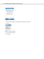
To install UConnect via downloading individual files:
1.
2.
Download the UConnect files from http://support.symbol.com to the host computer.
a.
On http://support.symbol.com, select Software Downloads.
b.
Select Mobile Computers.
c.
Select MC50.
d.
Select Four-Slot USB Cradle Drivers for MC50w vx.x, then download the .zip file to the development
computer.
Unzip the file. Copy the files to the Application partition of the mobile computer.
Accessories
3.
2-9
Perform a hard reset.
The Connect.reg file contains information on customizing UConnect's startup settings.
To install UConnect via the .CAB file:
1.
Download the UConnect .CAB file from http://support.symbol.com, to the host computer.
2.
Copy the file from the host computer to the mobile computer.
3.
On the mobile computer, navigate to the .CAB file and double-tap the file.
4.
Follow the screen prompts to install.
With this method, the .CAB file does not install the .cpy and .reg files.
Once installed, UConnect launches automatically upon mobile computer startup. Each mobile computer must
first form an ActiveSync partnership with a host computer for UConnect to successfully manage
synchronization.
Configuring UConnect
To customize default settings for UConnect, create a .reg file that overrides UConnect’s initial default settings.
Refer to UConnect.reg, included with UConnect, for information on setting custom hard reset and default
settings.
To customize UConnect temporarily (until the next hard reset):
1.
Tap
in the mobile computer’s command bar to display the SysTray menu.
Figure 2-11 UConnect SysTray Menu
2.
Tap Settings.
2 - 10 MC50 with Windows® Mobile 5.0 Integrator Guide
Figure 2-12 UConnect Settings Window
3.
Select the Allow UConnect to manage synchronization check box to allow UConnect to control docking
events and schedule synchronization sessions. UConnect launches ActiveSync when a mobile computer
is inserted in the cradle to synchronize the mobile computer and the host computer. If another inserted
mobile computer is synchronizing, UConnect reschedules synchronization based on the connection retry
interval setting.
Deselect this check box to restore control of cradle events to ActiveSync. This may be necessary when
temporarily connecting to a non-partnered host computer as a guest.
4.
In the Cancel sync if not connected in text box, enter the maximum time in seconds (between 5 and 120),
that UConnect waits for a connection to occur when starting a synchronization session. If UConnect cannot
connect to the host computer within this time, it cancels the session and reschedules based on the
connection retry interval setting. The default value is 15 seconds.
5.
In the If connection fails retry after text box, enter the number of seconds (between 30 and 9999) that
UConnect waits before attempting another synchronization after a failed or lost connection. The default
value is 30 seconds.
6.
In the When sync completes, resync after text box, enter the number of minutes (between 10 and 999) that
UConnect waits after successful synchronization before scheduling another session. The default value is
15 minutes.
7.
Select the Limit connect time per session to check box to specify the maximum number of minutes that
UConnect waits for a synchronization session to complete successfully. Then enter the number of minutes
(between 10 and 999) in the text box. The default value is enabled, 30 minutes.
If UConnect does not receive a synchronization complete notification from ActiveSync within this time,
UConnect disconnects from the host computer to allow recovery in instances where ActiveSync on the
host computer or mobile computer cannot complete synchronization.
8.
Tap Apply to apply UConnect setting changes.
Tap Restore to discard UConnect setting changes and return to the previous settings.
Tap Defaults to restore the default settings. Then tap Apply to apply the default settings.
Accessories 2 - 11
Manually Synchronizing
To synchronize a mobile computer immediately without waiting for a scheduled synchronization, tap File > Sync
Now. Note that this option is not active if the mobile computer is not in the cradle, or if synchronization is
already in progress.
Closing UConnect
To hide the UConnect user interface without exiting UConnect, tap
.
To exit UConnect and transfer control of docking events and synchronization to ActiveSync, tap File > Exit.
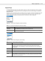
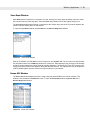
UConnect Status
To view the status of UConnect events, tap
> Status. The Status window displays the following information.
Figure 2-13 UConnect Status Window
• The Dock status: field indicates the current docked status of the mobile computer.
• The Last sync time: field indicates the date and time the last synchronization session started. If UConnect
has not performed synchronization, None appears. Use this field to determine if successful
synchronization occurred since the last time the mobile computer was docked.
• The Last sync status: field indicates the status of the most recent or currently active synchronization
session. Possible values are:
• Successful: The last synchronization session completed successfully.
• Waiting for connection: Synchronization started and UConnect is waiting for the connection with the
host to complete.
• In progress: Synchronization started and UConnect is waiting for a synchronization complete
notification from ActiveSync.
• Failed: Cable detached: Synchronization failed because the mobile computer is not inserted or the
USB cable is detached.
• Failed: No connection: UConnect could not establish a connection to the host computer.
• Failed: Connection lost: Connection to the host was lost before synchronization completed.
• Failed: Connect time exceeded: Synchronization did not complete within the maximum time allowed
per session.
2 - 12 MC50 with Windows® Mobile 5.0 Integrator Guide
• Failed: No reason: Synchronization failed for an unknown reason.
• The Next sync time: field indicates the date and time of the next scheduled synchronization session. If
UConnect is disabled, the mobile computer is not inserted, or a session is in progress, N/A appears.
• The synchronization history field displays information about docking events and synchronization session
status. This field can list up to 100 lines of synchronization history, and can be used to view the status of
previous synchronization sessions.
• Tap Clear to erase the contents of the synchronization history list box.
Charging
Insert the mobile computer into a slot to begin charging.
Figure 2-14 Mobile Computer Battery Charging
Battery Charging Indicators
The mobile computer’s charge LED shows the status of the battery charging in the mobile computer. See Table
1-2 on page 1-5 for charging status indications.
The standard battery fully charges in approximately 3.5 hours and the extended capacity battery fully charges
in approximately seven hours.
Accessories 2 - 13
Four Slot Ethernet Cradle
This section describes how to set up and use a Four Slot Ethernet cradle with the mobile computer. For cradle
communication setup procedures see, Chapter 3, ActiveSync.
The Four Slot Ethernet cradle:
• Provides 12 VDC power for operating the mobile computer.
• Enables data communication between the mobile computer (up to four) and a host computer, using an
Ethernet connection.
• Synchronizes information between the mobile computer and a host computer.
• Connects the mobile computer (up to four) to an Ethernet network.
• Simultaneously charges up to four batteries in the mobile computer.
NOTE
Use only a Motorola-approved power supply (p/n 50-14000-148) output rated 12 Vdc and minimum 3.33A.
The power supply is certified to EN60950 with SELV outputs. Use of alternative power supply will
invalidate any approval given to this device and may be dangerous.
HINWEIS Benutzen Sie nur eine von Motorola genehmigte Stromversorgung (Teilenr. 50-14000-148) mit einer
Ausgangsleistung von 12 V (Gleichstrom) und mindestens 3.33A. Die Stromversorgung ist nach
EN60950 für die Verwendung in SELV-Stromkreisen zertifiziert. Bei Verwendung eines anderen
Netzteils werden alle für das Gerät gewährten Genehmigungen außer Kraft gesetzt, und der Betrieb
kann gefährlich sein.
Setup
Connect the Ethernet cradle to a power source and to an Ethernet hub or a port on the host device.
Power Port
Ethernet Port 1
Ethernet Hub
Connection
Figure 2-15 Four Slot Ethernet Cradle Connection
2 - 14 MC50 with Windows® Mobile 5.0 Integrator Guide
Daisychaining Cradles
Daisychain up to four Ethernet cradles to connect several cradles to an Ethernet network.
To daisychain more than one cradle:
1.
Connect power to each cradle to daisychain, as shown in Setup on page 2-13.
2.
Connect an Ethernet cable to Port 1 of the first cradle as shown in Setup on page 2-13.
3.
Connect a second Ethernet cable between Port 2 of the first cradle, and Port 1 of the second.
4.
Connect up to two more cradles as described in Step 3.
Ethernet Port 1
Ethernet Port 2
Figure 2-16 Daisychaining Four Slot Ethernet Cradles
Bandwidth Considerations when Daisychaining
Each cradle added to the daisychain impacts the bandwidth provided to the inserted mobile computers,
particularly when the mobile computers attempt to send and receive at data rates that exceed the bandwidth
provided to the chain (typically 100 Mbps). If a mobile computer in a daisychained cradle does not use its
bandwidth, that bandwidth is allocated to other inserted mobile computers.
Table 2-4 shows available bandwidth, based on 100 Mpbs, for the maximum number of daisychained cradles,
with each attempting transmission at the maximum data rate.
Table 2-4 Daisychaining Bandwidth
Daisychained Cradles
Bandwidth Provided to Cradle
(Mbit/sec)
Inserted Mobile Computer’s Share of
Bandwidth
Cradle 1
100,000,000
20,000,000
Cradle 2
20,000,000
4,000,000
Cradle 3
4,000,000
800,000
Cradle 4
800,000
160,000
Cradle 5
160,000
32,000
Cradle 6
32,000
6,400
Cradle 7
6,400
1,280
Accessories 2 - 15
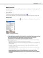
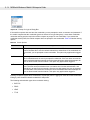
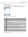
Ethernet Cradle Drivers
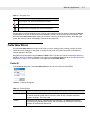
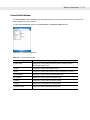
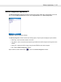
The MC50 includes Ethernet cradle drivers that initiate automatically when you place the mobile computer in a
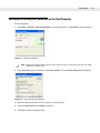
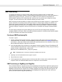
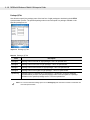
properly connected Four Slot Ethernet cradle. After inserting the MC50, configure the Ethernet connection:
1.
Tap Start > Settings > Connections tab > Network Cards icon. The Configure Network Adapters window
appears.
Figure 2-17 Configure Network Adapters Window
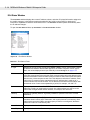
2.
In the My network card connects to: drop-down list, select the appropriate connection.
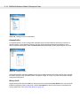
3.
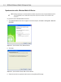
In the Tap an adapter to modify settings: list, select USB/Ethernet Series Adapter.
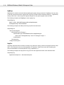
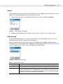
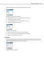
Figure 2-18 IP Address Tab
4.
In the IP address window, select the appropriate radio button:
• Use server-assigned IP address
or
• Use specific IP address. Enter the IP address, Subnet mask, and Default gateway, as needed.
5.
Tap the Name Servers tab.
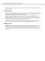
2 - 16 MC50 with Windows® Mobile 5.0 Integrator Guide
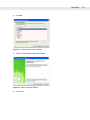
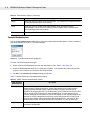
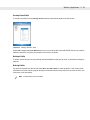
Figure 2-19 Name Servers Tab
6.
Enter the appropriate DNS, Alt DNS, WINS, and Alt WINS server addresses.
7.
Tap ok.
Figure 2-20 Adapters Dialog Box
8.
Tap ok to confirm the setup.
9.
Tap ok to exit.
Accessories 2 - 17
Charging
Insert the mobile computer into a slot to begin charging.
Figure 2-21 Mobile Computer Battery Charging
Battery Charging Indicators
The mobile computer’s charge LED shows the status of the battery charging in the mobile computer. See Table
1-2 on page 1-5 for charging status indications.
The standard battery fully charges in approximately 3.5 hours and the extended capacity battery fully charges
in approximately seven hours.
2 - 18 MC50 with Windows® Mobile 5.0 Integrator Guide
Four Slot Spare Battery Charger
This section describes how to set up and use the Four Slot Spare Battery Charger to charge up to four MC50
spare batteries.
NOTE
Use only a Motorola-approved power supply (p/n 50-14000-148) output rated 12 Vdc and minimum 3.33A.
The power supply is certified to EN60950 with SELV outputs. Use of alternative power supply will
invalidate any approval given to this device and may be dangerous.
HINWEIS Benutzen Sie nur eine von Motorola genehmigte Stromversorgung (Teilenr. 50-14000-148) mit einer
Ausgangsleistung von 12 V (Gleichstrom) und mindestens 3.33A. Die Stromversorgung ist nach
EN60950 für die Verwendung in SELV-Stromkreisen zertifiziert. Bei Verwendung eines anderen
Netzteils werden alle für das Gerät gewährten Genehmigungen außer Kraft gesetzt, und der Betrieb
kann gefährlich sein.
Spare Battery Charging
1.
Connect the charger to a power source.
2.
Insert the spare battery into a spare battery charging well and gently press down on the battery to ensure
proper contact.
Spare
Battery
Power Port
Spare Battery
Charging Well
(4)
Spare Battery
Charging LEDs
(4)
Figure 2-22 Four Slot Spare Battery Charger
Accessories 2 - 19
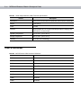
Battery Charging Indicators
An amber LED is provided for each battery charging well. See Table 2-5 for charging status indications. The
standard battery fully charges in approximately 2.5 hours and the extended capacity battery fully charges in
approximately six hours.
Table 2-5
Spare Battery LED Charging Indicators
LED
Indication
Off
No spare battery in slot; spare battery not placed correctly; cradle is not
powered.
Fast Blinking Amber
Error in charging; check placement of spare battery.
Slow Blinking Amber
Spare battery is charging.
Solid Amber
Charging complete.
2 - 20 MC50 with Windows® Mobile 5.0 Integrator Guide
Magnetic Stripe Reader (MSR)
This section describes how to set up and use the snap-on MSR with the mobile computer. The MSR snaps on
to the bottom of the mobile computer and can be easily removed when not in use.
When attached to the mobile computer, the MSR allows the mobile computer to capture data from magnetic
stripe cards. To download MSR data capture software, visit http://support.symbol.com.
Attaching and Removing
To attach, slide the MSR onto the bottom of the mobile computer and secure by snapping the arms into the
mobile computer housing.
Card Reader Slot
Arms
Figure 2-23 MSR Installation
To remove the MSR open the arms and pull the MSR from the mobile computer.
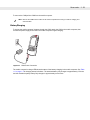
Using the MSR
The MSR3000 sample application illustrates how an application should handle MSR inputs (refer to the
Symbol Applications User’s Guide).
To use the MSR:
1.
Attach the MSR to the mobile computer.
2.
Power on the mobile computer.
3.
Tap Start > Programs > Samples icon > MSR icon to start the sample application.
4.
Swipe the magnetic stripe card through the MSR, with the magnetic stripe on the card facing down. Swipe
the card in either direction, from left to right or from right to left. For best results, gently press down on the
card while swiping to ensure contact with the bottom of the reader.
Accessories 2 - 21
Figure 2-24 Magnetic Stripe Card Swiping
2 - 22 MC50 with Windows® Mobile 5.0 Integrator Guide
Cable Adapter Module
This section describes how to set up and use the snap-on CAM with the mobile computer. The CAM snaps on
to the bottom of the mobile computer and can be easily removed when not in use.
Communications Port
Power Port
Figure 2-25 Cable Adapter Module
When attached to the mobile computer, the CAM:
• Provides power for operating the mobile computer, with the appropriate power connection.
• Provides Ethernet connection through the Ethernet port for communication with an Ethernet device, such
as a host computer or Ethernet hub. For communication setup procedures, see Chapter 3, ActiveSync.
• Charges the mobile computer’s battery, when used with the appropriate power supply.
NOTE
Use only a Motorola-approved power supply (p/n 50-14000-147) output rated 5.4 Vdc and minimum 3A.
The power supply is certified to EN60950 with SELV outputs. Use of alternative power supply will
invalidate any approval given to this device and may be dangerous.
HINWEIS Benutzen Sie nur eine von Motorola genehmigte Stromversorgung (Teilenr. 50-14000-147) mit einer
Ausgangsleistung von 5.4 V (Gleichstrom) und mindestens 3A. Die Stromversorgung ist nach EN60950
für die Verwendung in SELV-Stromkreisen zertifiziert. Bei Verwendung eines anderen Netzteils werden
alle für das Gerät gewährten Genehmigungen außer Kraft gesetzt, und der Betrieb kann gefährlich sein.
Attaching and Removing
To attach, slide the CAM onto the bottom of the mobile computer, until it snaps into place.
Figure 2-26 CAM Installation
Accessories 2 - 23
To remove the CAM pull the CAM from the mobile computer.
NOTE
Remove the CAM from the bottom of the mobile computer before using a cradle for charging and
communication.
Battery Charging
To charge the mobile computer’s battery through the CAM, attach the CAM to the mobile computer, then
connect the power supply to the CAM. The mobile computer begins charging.
Figure 2-27 CAM Power Connection
The mobile computer’s charge LED shows the status of the battery charging in the mobile computer. See Table
1-2 on page 1-5 for charging status indications. The standard battery fully charges in approximately 3.5 hours
and the extended capacity battery fully charges in approximately seven hours.
2 - 24 MC50 with Windows® Mobile 5.0 Integrator Guide
USB Connection
The CAM can connect to and communicate with a USB device, such as a host computer, through its data port.
See Chapter 3, ActiveSync for the host computer communication setup procedure.
To connect the CAM to a USB device, connect one end of the data cable to the data port on the CAM and the
other end to the USB port on the device.
Data Port
To Device
USB Port
Figure 2-28 CAM USB Connection
Accessories 2 - 25
Universal Battery Charger (UBC) Adapter
This section describes how to use the UBC adapter to charge a spare battery.
Use the UBC with a power supply as a standalone spare battery charger, or with the four station UBC2000 to
simultaneously charge up to four spare batteries. For additional information about the UBC2000, see the UBC
2000 Universal Battery Charger Product Guide (p/n 70-33188-xx).
NOTE
Use only a Motorola-approved power supply (p/n 50-14000-147) output rated 5.4 Vdc and minimum 3A.
The power supply is certified to EN60950 with SELV outputs. Use of alternative power supply will
invalidate any approval given to this device and may be dangerous.
HINWEIS Benutzen Sie nur eine von Motorola genehmigte Stromversorgung (Teilenr. 50-14000-147) mit einer
Ausgangsleistung von 5.4 V (Gleichstrom) und mindestens 3A. Die Stromversorgung ist nach EN60950
für die Verwendung in SELV-Stromkreisen zertifiziert. Bei Verwendung eines anderen Netzteils werden
alle für das Gerät gewährten Genehmigungen außer Kraft gesetzt, und der Betrieb kann gefährlich sein.
Setup
Power Port
Power Supply
AC Line Cord
Figure 2-29 UBC Adapter Power Connection
Battery Insertion and Removal
Insert the battery into the battery well with the charging contacts on the battery aligning with the charging pins
on the adapter, and gently press down on the battery to ensure proper contact.
To remove the battery, press the battery release and lift battery out of the well.
2 - 26 MC50 with Windows® Mobile 5.0 Integrator Guide
.
Battery
Battery Well
)
llow
)
REA
(Gre DY
en
Battery Release
CH
A
(Sol RGIN
id Ye
G
or S
TA
(Flas ND
B
hing
Yello Y or
w)
FA
(Flas ULT
hin
g Ye
llow
)
UBC Adapter
POWER
READY
(Green)
CHARGING or STANDBY or FAULT
(Solid Yellow)
(Flashing Yellow)
(Flashing Yellow)
Figure 2-30 UBC Adapter
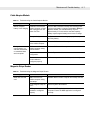
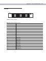
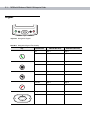
Battery Charging Indicators
To charge a spare battery using the UBC adapter, connect the power supply to the UBC (see Universal Battery
Charger (UBC) Adapter on page 2-25), then insert the spare battery. The spare battery begins charging.
The UBC’s charge LEDs show the status of the battery charging in the adapter. Table 2-6 shows battery
charging status indications. The standard battery fully charges in approximately 2.5 hours and the extended
capacity battery fully charges in approximately six hours.
POWER
READY
(Green)
CHARGING or STANDBY or FAULT
(Flashing Yellow)
(Solid Yellow)
(Flashing Yellow)
Figure 2-31 UBC Adapter LEDs
Table 2-6 UBC Adapter Charge LED Status Indications
LED
Indication
Description
POWER
Red
Power is connected to the UBC Adapter.
READY
Green
Charging complete.
Accessories 2 - 27
Table 2-6 UBC Adapter Charge LED Status Indications
LED
CHARGING
or
STANDBY or
FAULT
Indication
Description
Yellow
Normal charge.
Flashing
Yellow
The battery was deeply discharged and is being trickle charged to bring the
voltage up to the operating level. After operating level voltage is achieved the
battery charges normally.
Flashing
Yellow
Charging error, check placement of mobile computer/spare battery.
2 - 28 MC50 with Windows® Mobile 5.0 Integrator Guide
Chapter 3
ActiveSync
Chapter 3
Chapter 3 ActiveSync
Introduction
To communicate with various host devices, install Microsoft ActiveSync (version 4.1 or higher) on the host
computer. Use ActiveSync to synchronize information on the mobile computer with information on the host
computer. Changes made on the mobile computer or host computer appear in both places after
synchronization.
NOTE
Making an ActiveSync connection between the mobile computer and a host computer disables the WLAN
radio (if applicable). This is a Microsoft security feature to prevent connection to two networks at the
same time.
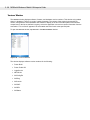
ActiveSync software:
• Allows working with mobile computer-compatible host applications on the host computer. ActiveSync
replicates data from the mobile computer so the host application can view, enter, and modify data on the
mobile computer.
• Synchronizes files between the mobile computer and host computer, converting the files to the correct
format.
• Backs up the data stored on the mobile computer. Synchronization is a one-step procedure that ensures
the data is always safe and up-to-date.
• Copies (rather than synchronizes) files between the mobile computer and host computer.
• Controls when synchronization occurs by selecting a synchronization mode, e.g., set to synchronize
continually while the mobile computer is connected to the host computer, or set to only synchronize on
command.
• Selects the types of information to synchronize and control how much data is synchronized.
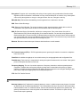
Installing ActiveSync
To install ActiveSync on the host computer, download version 4.1 or higher from the Microsoft web site at
http://www.microsoft.com. Refer to the installation included with the ActiveSync software.
3-2
MC50 with Windows® Mobile 5.0 Integrator Guide
Mobile Computer Setup
NOTE
Microsoft recommends installing ActiveSync on the host computer before connecting the mobile
computer.
The mobile computer can be set up to communicate either with a serial connection or a USB connection.
Chapter 2, Accessories provides the accessory setup and cable connection information for use with the mobile
computer. The mobile computer communication settings must be set to match the communication settings
used with ActiveSync.
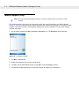
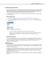
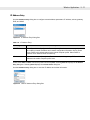
1.
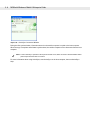
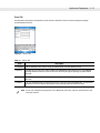
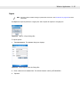
On the mobile computer tap Start > Programs > ActiveSync icon. The ActiveSync window appears.
Figure 3-32 ActiveSync Window
2.
Tap Menu > Connections.
3.
Select the connection type from the drop-down list.
4.
Tap OK to exit the Connections window and tap OK to exit the ActiveSync window.
5.
Proceed with installing ActiveSync on the host computer and setting up a partnership.
ActiveSync
3-3
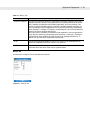
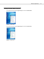
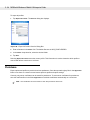
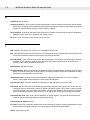
Setting Up an ActiveSync Connection on the Host Computer
To start ActiveSync:
1.
Select Start > Programs > Microsoft ActiveSync on the host computer. The ActiveSync window displays.
Figure 3-33 ActiveSync Window
NOTE
2.
Assign each mobile computer a unique device name. Do not try to synchronize more than one mobile
computer to the same name.
In the ActiveSync window, select File > Connection Settings. The Connection Settings window appears.
Figure 3-34 Connection Settings Window
3.
Select the appropriate check box for the type of connection used.
4.
Select the Show status icon in Taskbar check box.
5.
Select OK to save any changes made.
3-4
MC50 with Windows® Mobile 5.0 Integrator Guide
Synchronization with a Windows Mobile 5.0 Device
NOTE
Making an ActiveSync connection between the mobile computer and a host computer disables the WLAN
radio (if applicable). This is a Microsoft security feature to prevent connection to two networks at the
same time
To synchronize with a Windows Mobile 5.0 device:
1.
If the Get Connected window does not appear on the host computer, select Start > All Programs > Microsoft
ActiveSync.
Figure 3-35 Synchronization Setup Wizard Window
2.
Click Next.
Figure 3-36 Synchronization Directly With a Server Window
3.
Select the check box to synchronize with a server running Microsoft Exchange.
ActiveSync
4.
Click Next.
Figure 3-37 Synchronization Option Window
5.
Select the appropriate settings and click Next.
Figure 3-38 Wizard Complete Window
6.
Click Finish.
3-5
3-6
MC50 with Windows® Mobile 5.0 Integrator Guide
Figure 3-39 ActiveSync Connected Window
During the first synchronization, information stored on the mobile computer is copied to the host computer.
When the copy is complete and all data is synchronized, the mobile computer can be disconnect from the host
computer.
NOTE
The first ActiveSync operation must be performed with a local, direct connection. Windows Mobile retains
partnerships information after a cold boot.
For more information about using ActiveSync, start ActiveSync on the host computer, then see ActiveSync
Help.
Chapter 4
Application Deployment
Chapter 4
Chapter 4 Application Deployment
Introduction
This chapter describes new features in Windows Mobile 5.0 including new security features, how to package
applications, and procedures for deploying applications onto the mobile computer.
Security
The MC50 mobile computers implement a set of security policies that determine whether an application is
allowed to run and, if allowed, with what level of trust. To develop an application, you must know the security
configuration of the device, and how to sign an application with the appropriate certificate to allow the
application to run (and to run with the needed level of trust).
Application Security
Application security controls the applications that can run on the mobile computer.
•
Trusted - All applications must be digitally signed by a certificate on the mobile computer.
•
Prompted - User is prompted to allow unsigned applications to run.
•
Open - All applications run.
Developers can include their own certificates and provision the device to “trusted.”
Digital Signatures
Digital signatures provide a way to authenticate the author of EXEs, DLLs, and packages. Digitally signed
applications give users confidence that an application comes from where they think it comes from. For
example, if an end-user downloads an update package from the internet that is digitally signed with Symbol's
software certificate, they are assured that the package is authentic and that it was created by Symbol. By
enforcing the use of digital signatures, users can also prevent malicious applications from executing on the
mobile computer. For example, users can provision the mobile computer to only execute “trusted” applications
(digitally signed).
Motorola ships all Windows Mobile 5.0 based products in an “open” state, which means all signed and
unsigned applications should work. However, customers can still reconfigure their mobile computers to operate
in the “trusted” mode. This means that only applications signed with a certificate from the Privileged Execution
Trust Certificate Store can run.
4-2
MC50 with Windows® Mobile 5.0 Integrator Guide
To support the broadest number of deployments, third-party software developers should perform the following
when releasing software for a Windows Mobile 5.0 devices:
•
Sign all their EXEs & DLLs with their private key
•
Provide the corresponding public certificate to end-users so that it can be installed into Privileged
Execution Trust Certificate Store.
If the software is installed via a .CAB file, developer should also:
•
Sign the .CAB file with their private key
•
Provide the corresponding public certificate to end-users so that it can be installed into SPC Certificate
Store.
Locking Down a Mobile Computer
Like most configuration options in Windows Mobile 5.0, security settings are set via XML provisioning. For
example, to enforce the “trusted” model and only allow applications signed with a privileged certificate to run,
use the following provisioning document:
<wap-provisioningdoc>
<characteristic type=“SecurityPolicy”>
<!-- Disallow unsigned apps -->
<parm name=“4102” value=“0”/>
<!-- No Prompt -->
<parm name=“4122” value=“1”/>
</characteristic>
</wap-provisioningdoc>
For more information on various security options, refer to the Security Policy Settings topic in the latest
Windows Mobile documentation.
Application Deployment
4-3
Installing Certificates
Use XML provisioning to query and delete certificates from certificate stores. To add a new certificate the
Privileged Execution Trust Certificate Store, use the following sample provisioning document:
<wap-provisioningdoc>
<characteristic type=“CertificateStore”>
<characteristic type=“Privileged Execution Trust Authorities”>
<characteristic type=“657141E12FA45786F6A57CA6464032D4B3A55475”>
<parm name=“EncodedCertificate” value=“
This is sample text. This is sample text. This is sample text. This is sample text.
This is sample text. This is sample text. This is sample text. This is sample text.
This is sample text. This is sample text. This is sample text. This is sample text. =”/>
</characteristic>
</characteristic>
</characteristic>
</wap-provisioningdoc>
To create your own provisioning document with real certificate information:
1.
Obtain a certificate from a security provider such as VeriSign.
2.
Double-click on the certificate file (.CER) to open it.
3.
Click on the Details tab and locate the Thumbprint field.
4.
Copy the contents of the Thumbprint field and replace the value in the XML example above.
5.
Click the Copy to File… button.
6.
Click Next to start the Certificate Export Wizard.
7.
Select Base-64 encoded X.509 (.CER) and then click Next.
8.
Set the File Name to CertOutput.xml and click Next.
9.
Click Finish to export the certificate.
10. Open the exported file, CertOutput.xml, in a text editor (i.e., NotePad).
11. Copy the contents of the file (excluding the first line, last line, and CR/LF) and replace the value of the
“EncodedCertificate” parameter in the xml example above.
Device Management Security
You can control access to certain device settings and security levels, such as installing applications and
changing security settings. Refer to the Windows Mobile Version 5.0 Help file for information on device
management security.
4-4
MC50 with Windows® Mobile 5.0 Integrator Guide
Remote API Security
The Remote API (RAPI) enables applications that run on a desktop to perform actions on a remote device.
RAPI provides the ability to manipulate the file system on the remote device, including the creation and
deletion of files and directories. By default, Symbol ships with RAPI in the restricted mode. Certain tools, such
as RAPIConfig, may not work properly. Refer to the Windows Mobile Version 5.0 Help file for finding
information on Remote API security policies.
Packaging
NOTE
Applications compiled for Windows Mobile 5.0 are not backward-compatible with previous versions.
Packaging combines an application's executable files into a single file, called a package. This makes it easier
to deploy and install an application to the mobile computer. Package new applications and updates, such as
new DLL files, as CAB files, then deploy them to Windows Mobile 5.0 devices. Refer to the Microsoft Windows
Mobile 5.0 Help file for information on CAB files.
Deployment
To install applications onto the mobile computer, developers package the application and all required files into
a CAB file, then load the file onto the mobile computer using one of the following options:
•
Microsoft ActiveSync 4.1 or greater
•
Storage Card
•
AirBEAM
•
Image Update (for updating the operating system).
Refer to the Microsoft Windows Mobile 5.0 Help file for information on CAB files.
Installation Using ActiveSync
To install an application package:
•
Connect the mobile computer to a host computer using ActiveSync. See Chapter 3, ActiveSync for more
information.
•
Locate the package file on the host computer.
•
In ActiveSync on the host computer, open Explorer for the mobile computer.
•
Copy the CAB file from the host computer to the \temp directory on the mobile computer.
•
On the mobile computer, navigate to the \temp directory.
•
Tap on the application CAB file. The application installs on the mobile computer.
Application Deployment
4-5
Installation Using Storage Card
To install an application package:
•
Copy the package CAB file to a storage card using an appropriate storage card reader.
•
Install the storage card into the mobile computer. See Multi Media Card (MMC) / Secure Device (SD)
Card on page 2-3 for more information.
•
On the mobile computer, open File Explorer.
•
Open the Storage Card directory.
•
Tap the package CAB file. The application installs on the mobile computer.
Installation Using AirBEAM
See AirBEAM Smart on page 4-17 for information on AirBEAM.
Image Update
Windows Mobile 5.0 contains an Image Update feature that updates all operating system components. All
updates are distributed as update packages. Update packages can contain either partial or complete updates
for the operating system. Symbol distributes the update packages on the Symbol Developer Web Site,
http://devzone.symbol.com.
To update an operating system component, copy the update package to the mobile computer using one of a
variety of transports, including ActiveSync, an SD memory card, or Symbol AirBEAM. Then, initiate the update
using one of the following methods:
•
Double-tap the package file in File Explorer (similar to extracting a CAB file)
•
Perform a special boot sequence that initiates the update.
•
Use AirBEAM.
NOTE
The mobile computer must have at least 5 MB of free space to perform an OS update.
To initiate an update:
1.
Go to Support Central at http://support.symbol.com.
2.
Download the appropriate update package.
3.
Copy the update package to either the \temp directory on the mobile computer, or to a storage card.
4.
Connect the mobile computer to AC power. See Chapter 2, Accessories.
5.
Press the primary battery release on the mobile computer to partially eject the battery from the mobile
computer.
6.
While the battery is partially released, simultaneously press and release the left scan trigger and the
Power button.
NOTE
After you insert the battery you have 2 seconds to press the trigger or left scan button.
4-6
MC50 with Windows® Mobile 5.0 Integrator Guide
7.
Push the battery to fully re-insert it in the mobile computer. One audible click can be heard as the battery is
fully inserted.
8.
Press and hold the left scan button.
9.
Connect the mobile computer to AC power using the CAM or insert the mobile computer into a powered
cradle.
10. The Update Loader application first looks for a file on a storage card. If it does not find it, it looks in the
\temp directory.
When it finds the appropriate file, it loads the package onto the mobile computer. A progress bar displays
until the update completes.
11. The mobile computer re-boots.
12. The calibration screen appears.
NOTE
When initiating an update via a boot sequence, the update loader looks for updates first on the root of an
installed SD card and then in the \temp folder on the mobile computer’s persistent storage volume. A
response file, pkgs.lst, indicates which files to update. In most cases, Symbol provides this pkgs.lst file
with the update and you should only modify it when updating a splash screen partition. See Creating a
Splash Screen for more information.
Creating a Splash Screen
Use a bitmap file to create a customized splash screens for the mobile computer. Use Image Update with a
bitmap file, rather than a package file, to update the splash screen.
To create a custom splash screen:
Create a .bmp file using a graphic program with the following specifications:
1.
2.
•
Size: 240 x 296.
•
Colors: 8 bits per pixel (256 colors) for color displays.
Modify the bitmap file and save.
To load the splash screen on the mobile computer:
1.
Create a text file named pkgs.lst which contains the name of the bmp file. For example, mysplash.bmp.
2.
Copy the bmp file and the pkgs.lst file to one of the following:
•
SD card root directory
•
mobile computer’s \temp directory
•
mobile computer’s \Windows directory.
3.
If using an SD card, insert the SD card into the mobile computer.
4.
Perform a cold boot.
5.
Press the trigger or side scan button for 5 seconds while booting to invoke the Update Loader and install
the splash screen.
Application Deployment
4-7
XML Provisioning
To configure the settings on a mobile computer XML provisioning should be used. To install an XML
provisioning file on the mobile computer, create a Cabinet Provisioning File (CPF) file. A CPF file is similar to a
CAB file and contains just one file: _setup.xml. Like a CAB file, the CPF extension is associated with
WCELoad.EXE. Opening a CPF extracts the XML code and uses it to provision and configure the mobile
computer. The user receives an e-mail notification indicating success or failure.
XML Provisioning provides the ability to configure various features of the mobile computer (i.e., registry and file
system). However, some settings require security privileges. To change registry settings via a CPF file, you
need to have certain privileges (roles). Some registry keys require you to simply be an Authenticated User,
while other registry keys require you to be a Manager. Refer to the Windows Mobile 5.0 Help file, Metabase
Settings for Registry Configuration Service Provider section, for the default role settings in Windows Mobile
5.0.
For those registry settings that require the Manager role, the CPF file must be signed with a privileged
certificate installed on the device. Refer to the Microsoft Windows Mobile 5.0 Help file and the Windows Mobile
5.0 SDK for instructions and sample test certificates.
Creating an XML Provisioning File
To create a .cpf file:
1.
Create a valid provisioning XML file named _setup.xml using an XML editor or the tools supplied with
Visual Studio 2005. (For example, use the SampleReg.xml sample created in the RegMerge section below
and rename it _setup.xml.) Ensure the file contains the required parameters for the operation. Refer to the
Microsoft Windows Mobile 5.0 Help file for information.
2.
In the Windows Mobile 5.0 tools directory on the desktop computer (typically \Program Files\Windows CE
Tools\wce500\Windows Mobile 5.0 Pocket PC SDK\Tools), run the Makecab.exe utility, using the following
syntax to create a .cpf file from the _setup.xml file:
MakeCab.exe /D COMPRESS=OFF _setup.xml myOutCpf
NOTE
COMPRESS=OFF is required for backward compatibility with Pocket PC.
3.
Optionally, use the Authenticode tools to sign the .cpf file.
4.
Tap the filename to install.
5.
Certain applications and settings require a cold boot to take affect. In these cases, cold boot the mobile
computer. Refer to the Windows Mobile Version 5.0 Help file for more information.
XML Provisioning vs. RegMerge and CopyFiles
Prior to Windows Mobile 5.0, Symbol used two drivers (RegMerge and CopyFiles) to update the registry and to
copy files during a cold boot. With Windows Mobile 5.0, Symbol recommends using XML provisioning instead.
RegMerge and CopyFiles are supported for backward compatibility but Symbol may eliminate support in the
future. The following sections provide examples of how RegMerge and CopyFiles were used, and how to
perform the same function using XML provisioning.
4-8
MC50 with Windows® Mobile 5.0 Integrator Guide
RegMerge
RegMerge.dll is a built-in driver that allows updating the registry during a clean boot. RegMerge runs very early
in the boot process and looks for registry files (.reg files) in certain Flash File System folders (i.e., \Application)
during a clean boot. It then merges the registry changes into the system registry located in RAM.
The following example uses RegMerge to set a registry key:
SampleReg.reg
[HKEY_LOCAL_MACHINE\Hardware\DeviceMap\Backlight]
“BacklightIntensity”=dword:00000036
The following example uses XML provisioning to perform the same task:
SampleReg.xml
<wap-provisioningdoc>
<characteristic type=“Registry”>
<characteristic type=“HKLM\Hardware\DeviceMap\Backlight”>
<parm name=“BacklightIntensity” value=“54” datatype=“integer” />
</characteristic>
</characteristic>
</wap-provisioningdoc>
CopyFiles
CopyFiles copies files from one folder to another on a clean boot. During a clean boot CopyFiles looks for files
with a .CPY extension in the root of the Application FFS partition. These files are text files containing the
source and destination for the desired files to copy, separated by “>”.
The following example uses CopyFiles to copy a file from the \Application folder to the \Windows folder:
SampleCpy.cpy
\Application\example.txt > \Windows\example.txt
Application Deployment
4-9
The following example uses XML provisioning to perform the same task:
SampleCpy.xml
<wap-provisioningdoc>
<characteristic type=“FileOperation”>
<characteristic type=“\Windows” translation=“filesystem”>
<characteristic type=“MakeDir”/>
<characteristic type=“example.txt” translation=“filesystem”>
<characteristic type=“Copy”>
<parm name=“Source” value=“\Application\example.txt” translation=“filesystem”/>
</characteristic>
</characteristic>
</characteristic>
</characteristic>
</wap-provisioningdoc>
Storage
Windows Mobile 5.0 contains three types of file storage:
•
Random Access Memory (RAM)
•
Persistent Storage
•
Application folder.
Random Access Memory
Executing programs use RAM to store data. Data stored in RAM is lost upon a warm boot. RAM also included
a volatile file storage area called Cache Disk.
Volatile File Storage (Cache Disk)
Windows Mobile 5.0 memory architecture uses persistent storage for all files, registry settings, and database
objects to ensure data is retained even after a power failure. Persistent storage is implemented using Flash
memory technology which is generally slower than volatile RAM memory. In certain situations the speed of the
operation is more important than the integrity of the data. For these situations, Symbol has provided a small
volatile File Storage volume, accessed as the Cache Disk folder. Disk operations to the Cache Disk folder are
much faster than to any of the persistent storage volumes, but data is lost across warm boots and power
interruptions. Note that a backup battery powers RAM memory, including the Cache Disk, when you remove
the main battery for a short period of time.
The mobile computer uses the Cache Disk for temporary data that can be restored from other sources, for
example, for temporarily “caching” HTML web pages by a browser or generating formatted files to send to a
printer. Both situations benefit from the increased speed of the cache disk, but you can restore the data if
needed.
DO NOT use the Cache Disk as a method to improve application performance. Analyze applications that
perform slower in persistent storage to optimize disk access. Common areas for optimization include
4 - 10 MC50 with Windows® Mobile 5.0 Integrator Guide
minimizing the number of reads and writes to a file, removing unneeded debug logging, and minimizing file
flushing or closing files.
Persistent Storage
Windows Mobile 5.0 protects all data and applications from power-related loss. Because Windows Mobile 5.0
mounts the entire file system and registry in persistent storage (rather than using RAM), MC50 devices provide
a reliable storage platform even in the absence of battery power.
Persistent storage provides application developers with a reliable storage system available through the
standard file system and registry APIs. Persistent storage is optimized for large reads and writes; therefore,
applications reading and writing data in large chunks tend to outperform those applications reading and writing
small blocks of data. Data in persistent storage is lost upon a clean boot.
Persistent storage contains all the directories under the root directory except for Application, Cache Disk, and
Storage Card (if a storage card is installed). Persistent storage is approximately 60 MB (formatted).
Application Folder
The Application folder is a super-persistent storage that is persistent even after a clean boot. Accessing data in
the Application folder is slower than accessing persistent storage. The Application folder is used for
deployment and device-unique data. For example, network profiles can be stored in the Application folder so
that connection to the network is available after a cold boot. The Application folder is approximately 20 MB
(formatted).
Application Deployment 4 - 11
System Configuration Manager
Symbol Configuration Manager (SCM) is a utility that runs on the development computer and is used to create
configuration files. These files, when deployed to a mobile computer, set configuration parameters for that
device. The configurable options for a mobile computer are defined in an XML file that is available on Support
Central for that mobile computer. SCM is also available on Support Central.
SCM eliminates the potential user errors that occur when manually editing registry settings.
File Types
SCM uses three types of files:
•
Symbol Configuration Template (.SCT) files are XML files that define the configurable parameters for a
device.
•
Registry Configuration Service Provider XML files for device provisioning.
•
CAB Provisioning Format (.CPF) file which is a .CAB archive that contains the provisioning XML. This file
is downloaded to the mobile computer and merged upon a clean boot.
User Interface
SCM's user interface consists of a tree control on the left side of the window which displays all the
configuration categories, and a data grid table on the right which displays all the configurable controls for the
selected category. Figure 4-1 shows the main window for a device’s .sct file.
Figure 4-1 Main SCM Window
4 - 12 MC50 with Windows® Mobile 5.0 Integrator Guide
Menu Functions
Use the main menu to access the program functionality described in Table 4-1.
Table 4-1 SCM Menu Functions
Menu Item
Description
File Menu
Open Config File
Open a saved configuration file (.SCD).
Save Config Changes
Save changes to the currently loaded configuration file.
Restore All Defaults
Restore all parameter values to the default state. The default values are stored in
a Symbol Configuration template file (i.e., MC70w.sct).
Export Changes to .xml
Export the changed parameter values to an XML file.
Export Changes to .cpf
Export the changed parameter values to an CPF file.
Export all to .xml
Export all the parameter values to an XML file.
Export all to .cpf
Export all the parameter values to an CPF file.
Exit
Exit Symbol Configuration Manager.
Device Menu
Device type
Change the current device type template. Each template (available from Support
Central) must reside in the SCM directory.
Help Menu
About
Display the About dialog which shows the application version.
Parameter State Indicators
The first column of the data table displays parameter state indicators. The state indicators display one of the
states in Table 4-2 for a particular parameter:
Table 4-2 Parameter Status Indicators
Icon
Indicator
Description
Modified
This parameter was changed from its initial factory setting.
Invalid
This parameter is not valid for the selected device type. This can occur when a
configuration file for one type of device is loaded and the device type is changed
using the Device menu. Values marked “invalid” are not included in an exported.
Application Deployment 4 - 13
Window Status Bar
The SCM status bar found on the bottom right corner of the window contains the items in Table 4-3 from left to
right:
Table 4-3 Window Status Bar Items
Status Bar Item
Description
Invalid Count
Number of parameters not valid for the selected device.
Modified Count
Number of parameters modified from the factory defaults.
Device Type
Device type - version.
Figure 4-2 Sample Status Bar
The sample status bar in Figure 4-2 shows that the current configuration file contains 1 Invalid Parameter and
2 Modified Parameters.
File Deployment
The CPF file created by the SCM export function must be deployed to the mobile computer.
1.
Optionally, use the Authenticode tools to sign the .cpf file.
2.
Make the .cpf file read-only, then copy it to the mobile computer.
3.
Tap the filename to install.
4.
Certain applications and settings require a cold boot to take affect. In these cases, cold boot the mobile
computer. Refer to the Windows Mobile Version 5.0 Help file for more information.
4 - 14 MC50 with Windows® Mobile 5.0 Integrator Guide
Rapid Deployment Client
The Rapid Deployment (RD) Client facilitates software downloads to a mobile computer from a Mobility
Services Platform (MSP) Console’s FTP server. The MSP Console is a web-based interface to the wireless
infrastructure monitoring and management tools provided by the MSP Lite or MSP Enterprise server.
When software packages are transferred to the FTP server, the mobile computer on the wireless network can
download them. The location of software packages are encoded in RD bar codes. When the mobile computer
scans a bar code(s), the software package(s) is downloaded from the FTP server to the mobile computer.
Multiple mobile computers can scan a single RD bar code.
NOTE
For detailed information about the MSP Console, MSP Lite/MSP Enterprise servers and creating RD bar
codes, refer to the MSP User Guide.
Rapid Deployment Window
The Rapid Deployment window displays bar code scan status and provides features for resetting and exiting
the application.
To access the Rapid Deployment window tap Start > Rapid Deployment Client or Start > Programs > Rapid
Deployment Client icon.
Figure 4-3 Rapid Deployment Window
Application Deployment 4 - 15
Table 4-4 Rapid Deployment Window
Text Box/Button
Description
Please scan all of the bar
codes...
Displays the status of a scanned bar code.
Waiting - indicates the mobile computer is ready to scan a bar code.
OK - indicates the mobile computer successfully scanned a bar code. (The
Indicator LED bar on the mobile computer turns green and a beep sounds).
If there are no bar codes left to scan, the Rapid Deployment Configuring window
displays.
Bar codes left to scan...
Displays a list of any remaining bar codes to scan (1-D bar codes only). When all
required bar codes are scanned successfully, the Rapid Deployment Configuring
window displays.
About
Displays the Rapid Deployment Client Info window.
Reset
Removes any previously scanned data.
Exit
Closes the application. A confirmation window displays. Tap Yes to exit or No to
return to the Rapid Deployment window.
Note: Exiting the application prior to scanning all required bar codes discards any
scanned data collected up to that point.
Scanning RD Bar Codes
When the mobile computer scans and successfully decodes a single or multiple RD bar codes, the data
encoded in the bar code can:
•
Reset the mobile computer’s connection profile. A connection profile is a set of Wireless Application
parameters that the mobile computer uses to access the wireless network.
•
Initiate downloads of one or more software packages from an FTP server to the mobile computer.
NOTE
Currently, RD only recognizes AirBEAM software packages. See AirBEAM Smart on page 4-17 for more
information.
4 - 16 MC50 with Windows® Mobile 5.0 Integrator Guide
To scan an RD bar code:
1.
Obtain the appropriate RD bar code(s) from the MSP Administrator.
2.
Launch the RD application on the mobile computer. The Rapid Deployment window displays.
Ready to Scan
No Bar Codes Left to Scan
Ready to Scan
Bar Codes Left to Scan are Listed
Figure 4-4 Rapid Deployment Window
3.
4.
Scan the appropriate bar code(s) to complete the configuration and/or download.
a.
A PDF417 bar code (2-D bar code) can contain all download data in a single bar code. In this case,
only one bar code may be required to scan.
b.
Multi-part linear bar codes (1-D bar codes) can require scanning several bar codes. Scan these bar
codes in any order. The text box under Bar codes left to scan... shows the remaining bar codes to scan
(see Figure 4-4).
After successfully scanning all appropriate bar codes, the mobile computer connects to the server and the
Rapid Deployment Configuring window displays while network settings are configured.
Figure 4-5 Rapid Deployment Window - Configuring
NOTE
If the mobile computer cannot connect to the server, it continues to retry until you cancel (exit) the
application. If failure to connect to the server persists, see the MSP Administrator.
Application Deployment 4 - 17
When configuration is complete:
•
The Today screen displays.
•
A new Wireless profile is created on the mobile computer from the data encoded in the scanned bar
code(s). See Chapter 5, Wireless Applications for more information about wireless profiles.
•
The designated package(s) are downloaded from the FTP server.
AirBEAM Smart
The AirBEAM Smart product allows specially designed software packages to be transferred between a host
server and Symbol wireless handheld devices. Before transfer, AirBEAM Smart checks and compares
package versions, so that only updated packages are loaded.
AirBEAM Smart resides on radio-equipped client devices and allows them to request, download, and install
software, as well as to upload files and status data. A single communications session performs both file
download and upload. The ability to transfer software over a radio network can greatly reduce the logistical
efforts of client software management.
In an AirBEAM Smart system, a network-accessible host server acts as the storage point for the software
transfer. The AirBEAM Smart Client uses the industry standard FTP or TFTP file transfer protocols to check the
host system for updates and, if necessary, to transfer updated software.
NOTE
For more information about AirBEAM Smart, refer to the AirBEAM® Smart Windows® CE Client Product
Reference Guide (p/n 72-63060-xx).
AirBEAM Package Builder
In a typical distributed AirBEAM system, software to be transferred is organized into packages. In general, an
AirBEAM package is a set of files that are assigned attributes both as an entire package and as individual
component files. The package is assigned a version number and the transfer occurs when an updated version
is available.
An AirBEAM package can optionally contain developer-specified logic to be used to install the package.
Installation logic is typically used to update client device flash images or radio firmware. Examples of common
AirBEAM packages would include packages for custom client application software, radio firmware, and
AirBEAM Smart Client software.
Once these packages are built, they are installed on the host server for retrieval by the handheld device. Use
the AirBEAM Package Builder utility to define, generate, and install AirBEAM packages to a server. The
packages are then loaded from the server onto a client device equipped with an AirBEAM Smart Client
executable.
For instructions on how to define, generate, and install AirBEAM packages to the server, refer to the AirBEAM
Package Builder Product Reference Guide, p/n 72-55769-xx.
4 - 18 MC50 with Windows® Mobile 5.0 Integrator Guide
AirBEAM Smart Client
The AirBEAM Smart Client resides on the handheld mobile computer. It is configured with the server access
information, the names of the packages to be downloaded and other controlling parameters. When the
AirBEAM Smart Client is launched, the device connects to the specified FTP server and checks the packages
it is configured to look for. If the package version was updated, the client requests the transfer.
AirBEAM License
The AirBEAM Smart Client is a licensed software product. A license key file stored on the client device enables
the AirBEAM Smart Client's version synchronization functionality. Build the license key file into AirBEAM Smart
Client's image, or download it in a special AirBEAM package.
The AirBEAM license key file contains a unique key and a customer specific banner that appears when the
AirBEAM Smart Client version synchronization logic is invoked.
Configuring the AirBEAM Smart Client
1.
Tap Start > Programs > AirBEAM Client. The AirBEAM Smart window appears.
2.
Tap File > Configure. The AirBEAM configuration window appears.
Figure 4-6 AirBEAM Configuration Window
Use the configuration window to view and edit AirBEAM Smart Client configurations. This dialog box has seven
tabs that you can modify - Packages(1), Packages(2), Server, Misc(1), Misc(2), Misc(3), and Misc(4).
Application Deployment 4 - 19
Packages(1) Tab
Use this tab to specify the package name of the first four of eight packages to load during the AirBEAM
synchronization process. The specified package name must correspond to a package available on the
specified package server.
Figure 4-7 Package (1) Tab
Table 4-5 Package (1) Tab
Field
Description
Package 1
Package name of the first of eight packages. This is an optional field.
Package 2
Package name of the second of eight packages. This is an optional field.
Package 3
Package name of the third of eight packages. This is an optional field.
Package 4
Package name of the fourth of eight packages. This is an optional field.
NOTE
Do not enter inadvertent trailing spaces on the Packages(1) tab. Information entered in these fields are
case and space sensitive.
4 - 20 MC50 with Windows® Mobile 5.0 Integrator Guide
Packages(2) Tab
Use this tab to specify the package name of the last four of eight packages to load during the AirBEAM
synchronization process. The specified package name must correspond to a package available on the
specified package server.
Figure 4-8 Package (2) Tab
Table 4-6 Package (2) Tab
Field
Description
Package 5
Package name of the fifth of eight packages. This is an optional field.
Package 6
Package name of the sixth of eight packages. This is an optional field.
Package 7
Package name of the seventh of eight packages. This is an optional field.
Package 8
Package name of the eighth of eight packages. This is an optional field.
Upload Pkg
Package name of a package to be processed for “upload files” during the AirBEAM
synchronization process. The specified package name must correspond to a package
available on the specified package server. This is an optional field.
NOTE
Do not enter inadvertent trailing spaces on the Packages(2) tab. Information entered in these fields are
case and space sensitive.
Application Deployment 4 - 21
Server Tab
Use this tab to specify the configurations of the server to which the client connects during the package
synchronization process.
Figure 4-9 Server Tab
Table 4-7 Server Tab
Field
Description
IP Address
The IP Address of the server. It may be a host name or a dot notation format.
Directory
The directory on the server that contains the AirBEAM package definition files. All AirBEAM
package definition files are retrieved from this directory during the package synchronization
process.
User
The FTP user name that is used during the login phase of the package synchronization
process.
Password
The FTP password that corresponds to the FTP user specified in the User field. The specified
password is used during the login phase of the package synchronization process.
NOTE
Do not enter inadvertent trailing spaces on the Server tab. Information entered in these fields are case
and space sensitive.
4 - 22 MC50 with Windows® Mobile 5.0 Integrator Guide
Misc(1) Tab
Use this tab to configure various miscellaneous features.
Figure 4-10 Misc(1) Tab
Table 4-8 Misc(1) Tab
Field
Description
Auto-load
Use this drop-down list to specify how to invoke the AirBEAM Smart Client when the
client device is rebooted. Options are:
Disable: the AirBEAM Smart Client is not invoked automatically during the boot
sequence.
Interactive: the AirBEAM Smart Client is invoked during the boot sequence and
begins package synchronization. The Synchronization Dialog box appears and you
must tap OK when the process completes.
Non-interactive: the AirBEAM Smart Client is invoked during the boot sequence and
begins package synchronization. The Synchronization Dialog box appears, but you
don’t have to tap OK when the process completes. The Synchronization Dialog box
closes automatically.
Background: the AirBEAM Smart Client is invoked automatically during the boot
sequence. The package synchronization process starts automatically. Nothing is
displayed while the synchronization process is occurring.
RAM Management
This check box specifies whether the automatic RAM management is enabled during
package synchronization.
Enable this to invoke RAM management logic when there is not enough free disk
space to download a package. The RAM management logic attempts to remove any
discardable AirBEAM packages resident on the client.
Application Deployment 4 - 23
Table 4-8 Misc(1) Tab
Field
Description
Suppress Separator
This check box specifies whether to suppress the automatic insertion of a file path
separator character when the client generated server package definition file names.
When enabled, the parameter also disables appending .apd to the package. This
feature is useful for AS/400 systems, in which the file path separator character is a
period. Enabling this feature appends the server directory (Directory) and package
name (Package 1, Package 2, Package 3, and Package 4) “as is” when building the
name for the server package definition file.
When this feature is disabled, a standard file path separator is used to separate the
server directory (Directory) and package name (Package 1, Package 2, Package 3,
and Package 4) when building the name for the server package definition file. In
addition, an .apd extension is appended automatically.
TFTP
This check box specifies whether to use the TFTP protocol to download files. By
default, the AirBEAM Smart Client uses the FTP protocol.
WNMS
This check box specifies whether the AirBEAM Smart Client uploads a WNMS
information file at the end of each version synchronization.
Misc(2) Tab
Use this tab to configure various miscellaneous features.
Figure 4-11 Misc(2) Tab
4 - 24 MC50 with Windows® Mobile 5.0 Integrator Guide
Table 4-9 Misc(2) Tab
Field
Description
Auto-retry
Use this field to specify whether the AirBEAM Smart Client automatically retries if
synchronization fails.
If this feature is enabled, the AirBEAM Smart Client displays a pop-up dialog indicating
the retry attempt. The pop-up dialog appears for the number of seconds specified in the
Retry Delay field.
Values for this field are:
-1: the AirBEAM Smart Client automatically retries indefinitely.
0: the AirBEAM Smart Client does not automatically retry.
-0: the AirBEAM Smart Client automatically retries up to the number of times specified.
Retry Delay
This field specifies the amount of time, in seconds, that the AirBEAM Smart Client delays
before automatically retrying after a synchronization failure.
In-use Test
This check box specifies whether the AirBEAM Smart Client tests to determine if a file is
in use before downloading. If the In-use Test feature is enabled, the AirBEAM Smart
Client downloads a temporary copy of any files that are in use. If any temporary in-use
files are downloaded the AirBEAM Smart Client automatically resets the client to
complete copying the in-use files. If the In-use Test feature is disabled, the
synchronization process fails (-813) if any download files are in use.
Wait Welcome
This check box specifies whether the AirBEAM Smart Client waits for the WELCOME
windows to complete before automatically launching the synchronization process after
a reset.
Close Apps
This check box specifies whether the AirBEAM Smart Client automatically attempts to
close non-system applications prior to resetting the mobile unit. If enabled the AirBEAM
Smart Client sends a WM_CLOSE message to all non-system applications before
resetting the mobile unit. This feature offers applications the opportunity to prepare (i.e.,
close open files) for the pending reset.
Misc(3) Tab
Use this tab to configure various miscellaneous features.
Figure 4-12 Misc(3) Tab
Application Deployment 4 - 25
Table 4-10 Misc(3) Tab
Field
Description
Use DHCP server
This check box control specifies whether the AirBEAM Smart Client uses the
DHCP response option 66 to specify the IP address of the FTP/TFTP server.
If enabled, special RF network registry settings are required to force the DHCP
server to return the TFTP server name field (option 66). The special RF network
registry settings are included, but commented out, in the radio network registry
initialization files (essid_xxxx_yy.reg).
Use DHCP bootfile
This check box control specifies whether the AirBEAM Smart Client uses the
DHCP response option 67 to specify the Package and Package 1 parameters.
If enabled, special RF network registry settings are required to force the DHCP
server to return the Bootfile name field (option 67). The special RF network
registry settings are included, but commented out, in the radio network registry
initialization files (essid_xxxx_yy.reg).
Misc(4) Tab
Use this tab to configure various miscellaneous features.
Figure 4-13 Misc(4) Tab
4 - 26 MC50 with Windows® Mobile 5.0 Integrator Guide
Table 4-11 Misc(4) Tab
Field
Description
Sched Mode
Specifies whether (and how) the scheduled mode is enabled. If enabled,
schedule mode causes the AirBEAM synchronization process to occur
periodically. The selections are:
Disable - The schedule mode is disabled.
Fixed time - The schedule mode is enabled. The AirBEAM synchronization will
be launched once per day at the time specified in the Sched Time setting. The
synchronization will be launched every day Sched Time minutes past midnight.
Fixed period - The schedule mode is enabled. The AirBEAM synchronization
will be launched at a period by the Sched Time setting. The synchronization will
be launched every Sched Time minutes.
Sched Time
This edit control specifies, in minutes, the period for the schedule mode. The
Sched Mode setting specifies how the Sched Time value is used.
Sched Load
This drop-down menu specifies the load mode to be used for scheduled
synchronization, if enabled. The selections are:
Default - Specifies that the load mode specified in the Auto-load setting is to be
used for scheduled synchronization sessions.
Interactive - The Synchronization Dialog displays when a scheduled
synchronization session occurs. The user is required to press the OK button to
dismiss the dialog.
Non-interactive - The Synchronization Dialog displays when a scheduled
synchronization session occurs. The dialog is automatically dismissed when the
synchronization is complete, unless an error occurs. If an error occurs the user is
required to press the OK button to dismiss the dialog.
Background - Nothing is displayed when the scheduled synchronization sessions
occur.
Sched Prmpt
Specifies whether the AirBEAM client prompts the user when updates are
available in schedule mode. The settings are:
Disable - Updated packages are automatically downloaded. The user is not
prompted.
Alert - Updated packages are not automatically downloaded. The user is
prompted to warm boot the device to initiate the package downloads.
Launch - Updated packages are not automatically downloaded. The user is
prompted to start the package download. The user can defer the package
download by responding no to the prompt. The MAXNOPRESS registry setting
can be used to limit the number of times the user can defer the update.
Confirm - Updated packages are not automatically downloaded. This value
behaves the same as the Launch value, except that the user is required to confirm
an additional prompt before the download starts.
Application Deployment 4 - 27
Synchronizing with the Server
When synchronization begins, the AirBEAM Smart Client attempts to open an FTP session using the AirBEAM
Smart Client configuration. Once connected, the client processes the specified packages. Packages are
loaded only if the server version of a given package is different from the version loaded on the client. When
upload completes, the AirBEAM Smart Client closes the FTP session with the server.
The AirBEAM Smart Client can launch an FTP session with the server either manually, when initiated by the
user, or automatically.
Manual Synchronization
1.
Configure the AirBEAM Smart Client. See Configuring the AirBEAM Smart Client on page 4-18.
2.
From the main AirBEAM CE window, tap File > Synchronize. Once connected, the AirBEAM Synchronize
window appears.
Figure 4-14 AirBEAM Synchronize Window
- The Status List displays messages that indicate the synchronization progress.
- Tap OK to return to the Main Menu. This button remains inactive until synchronization completes.
- Tap Retry to restart synchronization. This button is active only if there is an error during
synchronization.
Automatic Synchronization
To configure the AirBEAM Smart Client to launch automatically, use the Misc(1) preference tab (see Misc(1)
Tab on page 4-22). When setting automatic synchronization, use the Auto-load drop-down list to specify how to
invoke the AirBEAM Smart Client when the client device reboots. See Misc(1) Tab on page 4-22 for
instructions on enabling Auto Sync.
AirBEAM Staging
The AirBEAM Smart staging support simplifies the process of staging custom or updated operating software
onto mobile devices directly from manufacturing. The staging support is part of the AirBEAM Smart CE Client
integrated in the mobile computer.
The AirBEAM Smart support defaults the AirBEAM Client configuration to a known set of values and launches
the AirBEAM Smart package download logic. A staging environment, including an RF network, FTP server,
and AirBEAM packages must be set up. Ideally, set up a staging network and server to match the default
AirBEAM Staging client configuration.
Invoke the AirBEAM Smart staging utility from the Application directory (tap Start > Programs > File Explorer >
Windows).
4 - 28 MC50 with Windows® Mobile 5.0 Integrator Guide
The AirBEAM Staging support provides several benefits:
•
Loading many devices simultaneously over the RF network.
•
A simple single dialog user interface used to quickly start the software installation process.
Symbol Mobility Developer Kits
The Symbol Mobility Developer Kit (SMDK) family of products allows you to write applications that take
advantage of the capture, move and manage capabilities of Symbol mobile computers. Go to Support Central
at http://support.symbol.com to download the appropriate developer kit.
Chapter 5
Wireless Applications
Chapter 5
Chapter 5 Wireless Applications
Introduction
Wireless Local Area Networks (LANs) allow mobile computers to communicate wirelessly and send captured
data to a host device in real time. The MC50 mobile computer supports the IEEE 802.11a, 802.11b and
802.11g standards. Before using the mobile computer on a WLAN, the facility must be set up with the required
hardware to run the wireless LAN and the mobile computer must be configured. Refer to the documentation
provided with the access points (APs) for instructions on setting up the hardware.
To configure the mobile computer, a set of wireless applications provide the tools to configure and test the
wireless radio in the mobile computer. The Wireless Application menu on the task tray provides the following
wireless applications:
• Wireless Status
• Wireless Diagnostics
• Find WLANs
• Manage Profiles
• Options
• Enable/Disable Radio (Windows Mobile 5.0 only)
• Log On/Off.
Tap the Signal Strength icon to display the Wireless Applications menu.
Figure 5-1 Wireless Applications Menu
5-2
MC50 with Windows® Mobile 5.0 Integrator Guide
Signal Strength Icon
The Signal Strength icon in the task tray indicates the mobile computer’s wireless signal strength as follows:
Table 5-1 Wireless Applications Icons, Signal Strength Descriptions
Icon
Status
Action
Excellent signal strength
Wireless LAN network is ready to use.
Very good signal strength
Wireless LAN network is ready to use.
Good signal strength
Wireless LAN network is ready to use.
Fair signal strength
Wireless LAN network is ready to use. Notify the network
administrator that the signal strength is only “Fair”.
Poor signal strength
Wireless LAN network is ready to use. Performance may not be
optimum. Notify the network administrator that the signal strength
is “Poor”.
Out-of-network range (not
associated)
No wireless LAN network connection. Notify the network
administrator.
No wireless LAN network card
detected
No wireless LAN network card detected or radio disabled. Notify
the network administrator.
Wireless Applications
Turning the WLAN Radio On and Off
To turn the WLAN radio off tap the Signal Strength icon and select Disable Radio.
Figure 5-2 Disable Radio
To turn the WLAN radio on tap the Signal Strength icon and select Enable Radio.
Figure 5-3 Enable Radio
5-3
5-4
MC50 with Windows® Mobile 5.0 Integrator Guide
Find WLANs Application
Use the Find WLANs application to discover available networks in the vicinity of the user and mobile computer.
To open the Find WLANs application, tap the Signal Strength icon > Find WLANs. The Find WLANs window
displays.
Figure 5-4 Find WLANs Window
NOTE
The Find WLANs display is limited to 32 items (ESSIDs or MAC addresses). A combination of up to 32
ESSIDs/APs may be displayed.
Manually enter valid ESSIDs not displayed in the Find WLANs window. See Figure 4-5 on page 4-6.
The Find WLANs list displays:
• WLAN Networks - Available wireless networks with icons that indicate signal strength and encryption
type. The signal strength and encryption icons are described in Table 4-1 and Table 4-3.
• Network Type - Type of network.
• Channel - Channel on which the AP is transmitting.
• Signal Strength - The signal strength of the signal from the AP.
Table 5-2 Signal Strength Icon
Icon
Description
Excellent signal
Very good signal
Good signal
Fair signal
Poor signal
Out of range or no signal
Wireless Applications
5-5
Table 5-3 Encryption Icon
Icon
Description
No encryption. WLAN is an infrastructure network.
WLAN is an Ad-Hoc network.
WLAN access is encrypted and requires a password.
Tap-and-hold on a WLAN network to open a pop-up menu which provides two options: Connect and Refresh.
Select Refresh to refresh the WLAN list. Select Connect to create a wireless profile from that network. This
starts the Profile Editor Wizard which allows you to set the values for the selected network. After editing the
profile, the mobile computer automatically connects to this new profile.
Profile Editor Wizard
Use the Profile Editor Wizard to create a new profile or edit an existing profile. If editing a profile, the fields
reflect the current settings for that profile. If creating a new profile, the known information for that WLAN
network appears in the fields.
Navigate through the wizard using the Next and Back buttons. Tap X to quit. On the confirmation dialog box,
tap No to return to the wizard or tap Yes to quit and return to the Manage Profiles window. See Manage Profiles
Application on page 5-21 for instructions on navigating the Profile Editor Wizard.
Profile ID
In the Profile ID dialog box in the Profile Editor Wizard, enter the profile name and the ESSID.
Figure 5-5 Profile ID Dialog Box
Table 5-4 Profile ID Fields
Field
Description
Name
The name and (WLAN) identifier of the network connection. Enter a user friendly name for
the mobile computer profile used to connect to either an AP or another networked
computer. Example: The Public LAN.
ESSID
The ESSID is the 802.11 extended service set identifier. The ESSID is 32-character
(maximum) string identifying the WLAN, and must match the AP ESSID for the mobile
computer to communicate with the AP.
5-6
MC50 with Windows® Mobile 5.0 Integrator Guide
NOTE
Two profiles with the same user friendly name are acceptable but not recommended.
Tap Next. The Operating Mode dialog box displays.
Operating Mode
Use the Operating Mode dialog box to select the operating mode (Infrastructure or Ad-Hoc) and the country
location.
Figure 5-6 Operating Mode Dialog Box
Table 5-5 Operating Mode Fields
Field
Description
Operating Mode
Select Infrastructure to enable the mobile computer to transmit and receive data with an
AP. Infrastructure is the default mode.
Select Ad Hoc to enable the mobile computer to form its own local network where mobile
computers communicate peer-to-peer without APs using a shared ESSID.
Country
Country determines if the profile is valid for the country of operation.
Use the Country drop-down list to select the country of operation for the adapter. This
feature ensures that the adapter is using country code information compatible with the
country code data that the associated access point uses. Choose International to
automatically use the country of the associated access point. Otherwise select the correct
country of operation.
Tap Next. If Ad-Hoc mode was selected the Ad-Hoc dialog box displays. If Infrastructure mode was selected the
Authentication dialog box displays. See Authentication on page 4-9 for instruction on setting up authentication.
Wireless Applications
5-7
Ad-Hoc
Use the Ad-Hoc dialog box to select the required information to control Ad-Hoc mode. This dialog box does not
appear if you selected Infrastructure mode. To select Ad-Hoc mode:
1.
Select a channel number from the Channel drop-down list. The default is Channel 1 (2412 MHz).
Figure 5-7 Ad-Hoc Settings Dialog Box
2.
Tap Next. The Encryption dialog box displays. See Encryption on page 4-17 for encryption options.
Authentication
Use the Authentication dialog box to configure authentication. If you selected Ad-Hoc mode, you can only
select None because Ad-Hoc authentication is not supported.
Select an authentication type from the drop-down list and tap Next. Selecting PEAP or TTLS displays the
Tunneled dialog box. Selecting None, TLS, or LEAP displays the Encryption dialog box. See Encryption on page
4-17 for encryption options. Table 5-6 lists the available authentication options.
Figure 5-8 Authentication Dialog Box
Table 5-6 Authentication Options
Authentication
Description
None
Default setting when authentication is not required on the network.
EAP TLS
Select this option to enable EAP TLS authentication. EAP TLS is an authentication
scheme through IEEE 802.1x. It authenticates users and ensures only valid users can
connect to the network. It also restricts unauthorized users from accessing transmitted
information by using secure authentication certificates.
5-8
MC50 with Windows® Mobile 5.0 Integrator Guide
Table 5-6 Authentication Options (Continued)
Authentication
Description
PEAP
Select this option to enable PEAP authentication. This method uses a digital certificate
to verify and authenticate a user's identity.
LEAP
Select this option to enable LEAP authentication, which is based on mutual
authentication. The AP and the connecting mobile computer require authentication
before gaining access to the network.
TTLS
Select this option to enable TTLS authentication.
Tunneled Authentication
Use the Tunneled Authentication dialog box to select the tunneled authentication options. There are different
selections available for PEAP or TTLS authentication.
Figure 5-9 Tunneled Authentication Dialog Box
To select a tunneled authentication type:
1.
Select a tunneled authentication type from the drop-down list. See Table 5-7 and Table 5-8.
2.
Select the User Certificate check box if a certificate is required. If you selected the TLS tunnel type that
requires a user certificate, the check box is already selected.
3.
Tap Next. The Installed User Certificates dialog box appears.
Table 5-7 lists the PEAP tunneled authentication options.
Table 5-7 PEAP Tunneled Authentication Options
PEAP Tunneled
Authentication
Description
MS CHAP v2
Microsoft Challenge Handshake Authentication Protocol version 2 (MS CHAP v2) is a
password-based, challenge-response, mutual authentication protocol that uses the
industry-standard Message Digest 4 (MD4) and Data Encryption Standard (DES)
algorithms to encrypt responses. The authenticating server challenges the access client
and the access client challenges the authenticating server. If either challenge is not
correctly answered, the connection is rejected. MS CHAP v2 was originally designed by
Microsoft as a PPP authentication protocol to provide better protection for dial-up and
virtual private network (VPN) connections. With Windows XP SP1, Windows XP SP2,
Windows Server 2003, and Windows 2000 SP4, MS CHAP v2 is also an EAP type.
TLS
EAP TLS is used during phase 2 of the authentication process. This method uses a user
certificate to authenticate.
Wireless Applications
5-9
Table 5-8 lists the TTLS tunneled authentication options.
Table 5-8 TTLS Tunneled Authentication Options
TTLS Tunneled
Authentication
Description
CHAP
Challenge Handshake Authentication Protocol (CHAP) is one of the two main
authentication protocols used to verify the user name and password for PPP Internet
connections. CHAP is more secure than PAP because it performs a three way
handshake during the initial link establishment between the home and remote
machines. It can also repeat the authentication anytime after the link is established.
MS CHAP
Microsoft Challenge Handshake Authentication Protocol (MS CHAP) is an
implementation of the CHAP protocol that Microsoft created to authenticate remote
Windows workstations. MS CHAP is identical to CHAP, except that MS CHAP is
based on the encryption and hashing algorithms used by Windows networks, and the
MS CHAP response to a challenge is in a format optimized for compatibility with
Windows operating systems.
MS CHAP v2
MS CHAP v2 is a password based, challenge response, mutual authentication
protocol that uses the industry standard Message Digest 4 (MD4) and Data
Encryption Standard (DES) algorithms to encrypt responses. The authenticating
server challenges the access client and the access client challenges the
authenticating server. If either challenge is not correctly answered, the connection is
rejected. MS CHAP v2 was originally designed by Microsoft as a PPP authentication
protocol to provide better protection for dial-up and virtual private network (VPN)
connections. With Windows XP SP1, Windows XP SP2, Windows Server 2003, and
Windows 2000 SP4, MS CHAP v2 is also an EAP type.
PAP
Password Authentication Protocol (PAP) has two variations: PAP and CHAP PAP. It
verifies a user name and password for PPP Internet connections, but it is not as
secure as CHAP, since it works only to establish the initial link. PAP is also more
vulnerable to attack because it sends authentication packets throughout the network.
Nevertheless, PAP is more commonly used than CHAP to log in to a remote host like
an Internet service provider.
MD5
Message Digest-5 (MD5) is an authentication algorithm developed by RSA. MD5
generates a 128-bit message digest using a 128-bit key, IPSec truncates the
message digest to 96 bits.
5 - 10 MC50 with Windows® Mobile 5.0 Integrator Guide
User Certificate Selection
If you checked the User Certificate check box on the Tunneled Authentication dialog box or if TLS is the selected
authentication type, the Installed User Certificates dialog box displays. Select a certificate from the drop-down
list of currently installed certificates before proceeding. The selected certificate’s name appears in the
drop-down list. If the required certificate is not in the list, install it.
Figure 5-10 Installed User Certificates Dialog Box
User Certificate Installation
To install a user certificate (EAP TLS only) and a server certificate for EAP TLS and PEAP authentication:
1.
Tap Install Certificate. The Credentials dialog box appears.
*********
Figure 5-11 Credentials Dialog Box
2.
Enter the User:, Pwd: (password), and Server: information in their respective text boxes.
3.
Tap Retrieve. A Progress dialog indicates the status of the certificate retrieval.
4.
Tap ok to exit.
After the installation completes, the Installed User Certs dialog box displays with the certificate available in the
drop-down list for selection.
NOTE
To successfully install a user certificate, the mobile computer must already be connected to a network from
which the server is accessible.
Wireless Applications 5 - 11
Server Certificate Selection
If you select the Validate Server Certificate check box, a server certificate is required. Select a certificate on the
Installed Server Certificates dialog box. An hour glass may appear as the wizard populates the existing
certificate list. If the required certificate is not listed, install it:
Figure 5-12 Installed Server Certificates Dialog Box
1.
Tap the Install Certificate button. A dialog lists the currently loaded certificate files found in the default
directory, with the default extension.
Figure 5-13 Browse Server Certificates
2.
Use the Folder: drop-down list to browse to the certificate.
3.
If necessary, use the Type: drop-down list to select a different certificate extension.
4.
Select a certificate in the list to install it.
Credential Cache Options
If you selected any of the password-based authentication types, you can select different credential caching
options. These options specify when the network credential prompts appear: at connection, on each resume,
or at a specified time.
Entering the credentials directly into the profile permanently caches the credentials. In this case, the mobile
computer does not require user login. If a profile does not contain credentials entered through the configuration
editor, you must log in to the mobile computer before connecting.
Caching options only apply on credentials entered through the login dialog box.
5 - 12 MC50 with Windows® Mobile 5.0 Integrator Guide
Figure 5-14 Prompt for Login at Dialog Box
If the mobile computer does not have the credentials, you are prompted to enter a username and password. If
the mobile computer has the credentials (previous entered via a login dialog box), it uses these credentials
unless the caching options require the mobile computer to prompt for new credentials. If you entered the
credentials via the profile, the mobile computer does not prompt for new credentials. Table 4-9 lists the caching
options.
Table 5-9 Cache Options
Description
At Connect
Select this option to prompt for credentials whenever the WCS tries to connect to a new
profile. Deselect this to use the cached credentials to authenticate. If the credentials are
not cached, you are prompted to enter credentials. This option only applies when logged
in.
On Resume
Selecting this reauthenticates an authenticated user when a suspend/resume occurs.
Once reauthenticated, the user is prompted for credentials. If the user does not enter the
same credentials that were entered prior to the suspend/resume within three attempts, the
user is disconnected from the network. This option only applies when logged in.
At Time
Select this option to perform a local verification on an authenticated user at a specified
time. The time can be an absolute time or a relative time from the authentication, and
should be in at least 5 minute intervals. Once the time has passed, the user is prompted
for credentials. If the user does not enter the correct credentials within three attempts, the
user is disconnected from the network. This option only applies when logged in.
Entering credentials applies these credentials to a particular profile. Logging out clears all cached credentials.
Editing a profile clears all cached credentials for that profile.
The following authentication types have credential caching:
• EAP TLS
• PEAP
• LEAP
• TTLS.
Wireless Applications 5 - 13
Selecting the At Time check box displays the TIme Cache Options dialog box.
Figure 5-15 Time Cache Options Dialog Box
1.
Tap the Interval radio button to check credentials at a set time interval.
2.
Enter the value in minutes in the Min box.
3.
Tap the At (hh:mm) radio button to check credentials at a set time.
4.
Tap Next. The At Time dialog box appears.
Figure 5-16 At Time Dialog Box
5.
Enter the time using the 24 hour clock format in the (hh:mm) box.
6.
Tap > to move the time to the right. Repeat for additional time periods.
7.
Tap Next. The User Name dialog box displays.
User Name
The user name and password can be entered (but is not required) when the profile is created. When a profile
authenticates with credentials that were entered in the profile, caching rules do not apply. Caching rules only
apply on credentials that are entered through the login dialog box.
Figure 5-17 Username Dialog Box
5 - 14 MC50 with Windows® Mobile 5.0 Integrator Guide
Password
Use the Password dialog box to enter a password. If EAP/TLS is the selected authentication type, the
password is not required and the field is disabled.
Figure 5-18 Password Dialog Box
1.
Enter a password in the Password field.
2.
Select the Advanced ID check box, if advanced identification is required.
3.
Tap Next. The Encryption dialog box displays. See Encryption on page 4-17.
Advanced Identity
Use the Advanced ID dialog box to enter the 802.1X identity to supply to the authenticator. This value can be 63
characters long and is case sensitive. In TTLS and PEAP, it is recommended entering the identity anonymous
(rather than a true identity) plus any desired realm (e.g., anonymous@myrealm). A user ID is required before
proceeding.
NOTE
When authenticating with a Microsoft IAS server, do not use advanced identity.
Figure 5-19 Advanced Identity Dialog Box
Tap Next. The Encryption dialog box displays.
Wireless Applications 5 - 15
Encryption
Use the Encryption dialog box to select an encryption type. The drop-down list includes encryption types
available for the selected authentication type. See Table 4-11 for these encryption types.
Figure 5-20 Encryption Dialog Box
Table 5-10 Encryption Options
Encryption
Description
Open
Select Open (the default) when no data packet encryption is needed over the network.
Selecting this option provides no security for data transmitting over the network.
40-Bit WEP
Select 40-Bit WEP to use 40-bit key length WEP encryption. WEP keys are manually
entered in the edit boxes. Only the required number of edit boxes for a key length is
displayed (10 Hex digit value for 40-bit keys). Use the Key Index drop-down list to
configure the four WEP keys. The adapter uses the selected key. Note: The default Hex
digit keys are visible any time they are used. As a security precaution after setting the key
values for the network, the digits are replaced with asterisks * in the encryption key fields.
If the associated AP uses an optional passkey, the active adapter WLAN profile must use
one as well. The passkey is a plain text representation of the WEP keys displayed in the
encryption dialog box. The passkey provides an easy way to enter WEP key data without
having to remember the entire 40-bit (10 character) Hex digit string.
128-Bit WEP
Select 128-Bit WEP to use 128-bit key length WEP encryption. WEP keys are manually
entered in the edit boxes. Only the required number of edit boxes for a key length is
displayed (26 Hex digit value for 128-bit keys). Use the Key Index drop-down list to
configure the four WEP keys. The adapter uses the selected key. Note: The default Hex
digit keys are visible any time they are used. As a security precaution after setting the key
values for the network, the digits are replaced with asterisks * in the encryption key fields.
If the associated AP uses an optional passkey, the active adapter WLAN profile must use
one as well. The passkey is a plain text representation of the WEP keys displayed in the
encryption dialog box. The passkey provides an easy way to enter WEP key data without
having to remember the entire 128-bit (26 character) Hex digit string.
TKIP
Select this option to use Wireless Protected Access (WPA) via TKIP. Manually enter the
shared keys in the passkey field. Tap Next to display the passkey dialog box. Enter an 8
to 63 character string.
5 - 16 MC50 with Windows® Mobile 5.0 Integrator Guide
Table 5-11 Encryption / Authentication Matrix
Encryption
Authentication
Open
WEP
TKIP
None
Yes
Yes
Yes
EAP TLS
No
Yes
Yes
PEAP
No
Yes
Yes
LEAP
No
Yes
Yes
TTLS
No
Yes
Yes
Key Entry Page
If you select either 40-Bit WEP or 128-Bit WEP, and set Authentication to None, the wizard proceeds to the key
entry dialog box unless the Use Passkey check box was selected in the Encryption dialog box (see Figure 4-21
on page 4-17). To enter the key information:
1.
Enter the 40-bit or 128-bit keys into the fields.
2.
Tap Next.
40-Bit WEP Keys Dialog Box 128-Bit WEP Keys Dialog Box
Figure 5-21 40-Bit and 128-Bit WEP Keys Dialog Boxes
Passkey Dialog
When you select None as an authentication and WEP as an encryption, you can choose to enter a passkey by
checking the Use PassKey check box. The user is prompted to enter the passkey. For WEP, the Use PassKey
checkbox is only available if the authentication is None.
When you select None as an authentication and TKIP as an encryption, you must enter a passkey. The user
cannot enter a passkey if the encryption is TKIP and the authentication is anything other than None.
Figure 5-22 Passkey Dialog Box
Tap Next. The IP Address Entry dialog box displays.
Wireless Applications 5 - 17
IP Address Entry
Use the IP Address Entry dialog box to configure network address parameters: IP address, subnet, gateway,
DNS, and WINS.
Figure 5-23 IP Address Entry Dialog Box
Table 5-12 IP Address Entry
Encryption
Description
DHCP
Select Dynamic Host Configuration Protocol (DHCP) from the IP Address Entry drop-down
list to obtain a leased IP address and network configuration information from a remote
server. DHCP is the default setting for the mobile computer profile. When DHCP is
selected, the IP address fields are read-only.
Static
Select Static to manually assign the IP, subnet mask, default gateway, DNS, and WINS
addresses the mobile computer profile uses.
Select either DHCP or Static from the drop-down list and tap Next. Selecting Static IP displays the IP Address
Entry dialog box. Selecting DHCP displays the Transmit Power dialog box.
Use the IP Address Entry dialog box to enter the IP address and subnet information.
Figure 5-24 Static IP Address Entry Dialog Box
5 - 18 MC50 with Windows® Mobile 5.0 Integrator Guide
Table 5-13 Static IP Address Entry Fields
Field
Description
IP Address
The Internet is a collection of networks with users that communicate with each other. Each
communication carries the address of the source and destination networks and the
particular machine within the network associated with the user or host computer at each
end. This address is called the IP address (Internet Protocol address). Each node on the
IP network must be assigned a unique IP address that is made up of a network identifier
and a host identifier. Enter the IP address as a dotted-decimal notation with the decimal
value of each octet separated by a period, for example, 192.168.7.27.
Subnet Mask
Most TCP/IP networks use subnets to manage routed IP addresses. Dividing an
organization's network into subnets allows it to connect to the Internet with a single shared
network address, for example, 255.255.255.0.
Select the Advanced check box, then tap NEXT to display the Advanced Address Entry dialog box. Enter the
Gateway, DNS, and WINS address. Tap NEXT without selecting the Advanced check box to display the
Transmit Power dialog box.
Figure 5-25 Advanced Address Entry Dialog Box
The IP information entered in the profile is only used if you selected the Enable IP Mgmt check box in the
Options > System Options dialog box (System Options on page 4-38). If you didn’t select this, the IP
information in the profile is ignored and the IP information entered in the Microsoft interface applies.
Table 5-14 IP Config Advanced Address Entry Fields
Field
Description
G/W
The default gateway forwards IP packets to and from a remote destination.
DNS
The Domain Name System (DNS) is a distributed Internet directory service. DNS
translates domain names and IP addresses, and controls Internet email delivery. Most
Internet services require DNS to operate properly. If DNS is not configured, Web sites
cannot be located and/or email delivery fails.
WINS
WINS is a Microsoft® Net BIOS name server. WINS eliminates the broadcasts needed to
resolve computer names to IP addresses by providing a cache or database of
translations.
Tap Next. The Transmit Power dialog box displays.
Wireless Applications 5 - 19
Transmit Power
The Transmit Power drop-down list contains different options for Ad-Hoc and Infrastructure mode. Automatic
(i.e., use the current AP settings) and Power Plus (use higher than the current AP settings) are available for
Infrastructure mode.
Adjusting the radio transmission power level enables the user to expand or confine the transmission area with
respect to other wireless devices that could be operating nearby. Reducing coverage in high traffic areas
improves transmission quality by reducing the amount of interference in that coverage area.
Figure 5-26 Transmit Power Dialog Box (Infrastructure Mode)
Table 5-15 Transmit Power Dialog Box (Infrastructure Mode)
Field
Description
Automatic
Select Automatic (the default) to use the AP power level.
Power Plus
Select Power Plus to set the mobile computer transmission power one level higher
than the level set for the AP.
Figure 5-27 Transmit Power Dialog Box (Ad-Hoc Mode)
Table 5-16 Power Transmit Options (Ad-Hoc Mode)
Field
Description
Full
Select Full power for the highest transmission power level. Select Full power when
operating in highly reflective environments and areas where other devices could be
operating nearby, or when attempting to communicate with devices at the outer edge of a
coverage area.
30 mW
Select 30 mW to set the transmit power level to 30 mW.
15 mW
Select 15 mW to set the transmit power level to 15 mW.
5 mW
Select 5 mW to set the transmit power level to 5 mW.
1 mW
Select 1 mW for the lowest transmission power level. Use this level when communicating
with other devices in very close proximity, or in instances where you expect little or no radio
interference from other devices.
5 - 20 MC50 with Windows® Mobile 5.0 Integrator Guide
Tap Next to display the Battery Usage dialog box.
Battery Usage
Use the Battery Usage dialog box to select power consumption of the wireless LAN. There are three settings
available: CAM, Fast Power Save, and MAX Power Save. Battery usage cannot be configured in Ad-Hoc
profiles.
Figure 5-28 Battery Usage Dialog Box
NOTE
Power consumption is also related to the transmit power settings.
Table 5-17 Battery Usage Options
Field
Description
CAM
Continuous Aware Mode (CAM) provides the best network
performance, but yields the shortest battery life.
Fast Power Save
Fast Power Save (the default) performs in the middle of CAM and MAX
Power Save with respect to network performance and battery life.
MAX Power Save
Max Power Save yields the longest battery life while potentially reducing
network performance. In networks with minimal latency, Max Power
Save performs as well as Fast Power Save, but with increased battery
conservation.
Wireless Applications 5 - 21
Manage Profiles Application
The Manage Profiles window provides a list of user-configured wireless profiles. Define up to 32 profiles at any
one time. To open the Manage Profiles window, tap the Signal Strength icon > Manage Profiles.
Figure 5-29 Manage Profiles Window
Icons next to each profile identify the profile’s current state.
Table 5-18 Profile Icons
Icon
No Icon
Description
Profile is not selected, but enabled.
Profile is disabled.
Profile is cancelled. A cancelled profile is disabled until a connect or login function is performed
through the configuration editor.
Profile is in use and describes an infrastructure profile not using encryption.
Profile is in use and describes an infrastructure profile using encryption.
Profile is in use and describes an ad-hoc profile not using encryption.
Profile is in use and describes an ad-hoc profile using encryption.
Profile is not valid in the device current operating regulatory domain.
The profiles are listed in priority order for use by the automatic roaming feature. Change the order by moving
profiles up or down. To edit existing profiles, tap and hold one in the list and select an option from the menu to
connect, edit, disable (enable), or delete the profile. (Note that the Disable menu item changes to Enable if the
profile is already disabled.)
5 - 22 MC50 with Windows® Mobile 5.0 Integrator Guide
Figure 5-30 Manage Profiles Context Menu
Changing Profiles
A completed profile is a set of configuration settings that can be used in different locations to connect to a
wireless network. Create different profiles to have pre-defined operating parameters available for use in
various network environments. When the WLAN Profiles window displays, existing profiles appear in the list.
Figure 5-31 Manage Profiles
Tap and hold a profile and select Connect from the pop-up menu to set this as the active profile. Once selected,
the mobile computer uses the authentication, encryption, ESSID, IP Config, and power consumption settings
configured for that profile.
Editing a Profile
Tap and hold a profile and select Edit from the pop-up menu to display the Profile Wizard where you can set the
ESSID and operating mode for the profile. Use the Profile Wizard to edit the profile power consumption and
security parameters. See Profile Editor Wizard on page 4-6.
Wireless Applications 5 - 23
Creating a New Profile
To create new profiles from the Manage Profiles window, tap-and-hold anywhere in this window.
Figure 5-32 Manage Profiles - Add
Select Add to display the Profile Wizard wherein you can set the profile name and ESSID. Set security, network
address information, and power consumption level for the new profile.
Deleting a Profile
To delete a profile from the list, tap and hold and select Delete from the pop-up menu. A confirmation dialog box
appears.
Ordering Profiles
Tap and hold a profile from the list and select Move Up or Move Down to order the profile. If the current profile
association is lost, the mobile computer attempts to associate with the first profile in the list, then the next, until
it achieves a new association.
NOTE
Profile Roaming must be enabled.
5 - 24 MC50 with Windows® Mobile 5.0 Integrator Guide
Export a Profile
To export a profile to a registry file, tap and hold a profile from the list and select Export from the pop-up menu.
The Save As dialog box displays with the Application folder and a default name of WCS_PROFILE{profile
GUID}.reg (Globally Unique Identifier).
Figure 5-33 Save As Dialog Box
If required, change the name in the Name field and tap Save. A confirmation dialog box appears after the export
completes.
Wireless Status Application
To open the Wireless Status window, tap the Signal Strength icon > Wireless Status. The Wireless Status window
displays information about the wireless connection.
Figure 5-34 Wireless Status Window
The Wireless Status window contains the following options. Tap the option to display the option window.
• Signal Strength - provides information about the connection status of the current wireless profile.
• Current Profile - displays basic information about the current profile and connection settings.
Wireless Applications 5 - 25
• IPv4 Status - displays the current IP address, subnet, and other IP related information assigned to the
mobile computer.
• Wireless Log - displays a log of important recent activity, such as authentication, association, and DHCP
renewal completion, in time order.
• Versions - displays software, firmware, and hardware version numbers.
• Quit - exits the Wireless Status window.
Option windows contain a back button
to return to the main Wireless Status window.
Signal Strength Window
The Signal Strength window provides information about the connection status of the current wireless profile
including signal quality, missed beacons, and transmit retry statistics. The BSSID address (shown as AP MAC
Address) displays the AP currently associated with the connection. In Ad-Hoc mode, the AP MAC Address
shows the BSSID of the Ad-Hoc network. Information in this window updates every 2 seconds.
To open the Signal Status window, tap Signal Strength in the Wireless Status window.
Figure 5-35 Signal Strength Window
After viewing the Signal Strength window, tap the back button to return to the Wireless Status window.
5 - 26 MC50 with Windows® Mobile 5.0 Integrator Guide
Table 5-19 Signal Strength Status
Field
Signal
Description
Displays the Relative Signal Strength Indicator (RSSI) of the signal transmitted
between the AP and mobile computer. As long as the Signal Quality icon is green
the AP association is not jeopardized. If the icon is red (poor signal), an association
with a different AP could be warranted to improve the signal. The signal strength
icon changes depending on the signal strength.
Excellent Signal
Very Good Signal
Good Signal
Fair Signal
Poor Signal
Out of Range (no signal)
The radio card is off or there is a problem communicating with the radio card.
Status
Indicates if the mobile computer is associated with the AP.
Signal Quality
Displays a text format of the Signal icon.
Tx Retries
Displays a percentage of the number of data packets the mobile computer
retransmits. The fewer transmit retries, the more efficient the wireless network is.
Missed Beacons
Displays a percentage of the amount of beacons the mobile computer missed. The
fewer transmit retries, the more efficient the wireless network is. Beacons are
uniform system packets broadcast by the AP to keep the network synchronized.
Signal Level
The AP signal level in decibels per milliwatt (dBm).
Noise Level
The background interference (noise) level in decibels per milliwatt (dBm).
SNR
The access point/mobile computer Signal to Noise Ratio (SNR) of signal strength to
noise (interference) in decibels per milliwatt (dBm).
Association Count
Displays the number of APs the mobile computer connects to while roaming.
AP MAC Address
Displays the MAC address of the AP to which the mobile computer is connected.
Transmit Rate
Displays the current rate of the data transmission.
Wireless Applications 5 - 27
Current Profile Window
The Current Profile window displays basic information about the current profile and connection settings. This
window updates every two seconds.
To open the Current Profile window, tap Current Profile in the Wireless Status window.
Figure 5-36 Current Profile Window
Table 5-20 Current Profile Window
Field
Description
Profile Name
Displays the current profile name the mobile computer uses to
communicate with the AP.
ESSID
Displays the current profile ESSID name.
Mode
Displays the current profile mode, either Infrastructure or Ad-Hoc.
Authentication
Displays the current profile’s authentication type.
Encryption
Displays the current profile’s encryption type.
Channel
Displays the current profile’s channel setting.
Country
Displays the current profile’s country setting.
Transmit Power
Displays the radio transmission power level.
5 - 28 MC50 with Windows® Mobile 5.0 Integrator Guide
IPv4 Status Window
The IPv4 Status window displays the current IP address, subnet, and other IP related information assigned to
the mobile computer. It also allows renewing the address if the profile is using DHCP to obtain the IP
information. Tap Renew to initiate a full DHCP discover. The IPv4 Status window updates automatically when
the IP address changes.
To open the IPv4 Status window, tap IPv4 Status in the Wireless Status window.
Figure 5-37 IPv4 Status Window
Table 5-21 IPv4 Status Fields
Field
Description
IP Type
Displays the IP type for the current profile: DHCP or Static. If the IP type is DHCP, leased
IP address and network address data appear for the mobile computer. If the IP type is
Static, the values displayed were input manually in the IP Config tab on page 4-19.
IP Address
Displays the mobile computer’s IP address. The Internet is a collection of networks with
users that communicate with each other. Each communication carries the address of the
source and destination networks and the particular machine within the network associated
with the user or host computer at each end. This address is called the IP address. Each
node on the IP network must be assigned a unique IP address that is made up of a
network identifier and a host identifier. The IP address as a dotted-decimal notation with
the decimal value of each octet separated by a period, for example, 192.168.7.27.
Subnet
Displays the subnet address. Most TCP/IP networks use subnets to manage routed IP
addresses. Dividing an organization's network into subnets allows it to connect to the
Internet with a single shared network address, for example, 255.255.255.0.
Gateway
Displays the gateway address. A gateway forwards IP packets to and from a remote
destination.
DCHP Server
The Domain Name System (DNS) is a distributed Internet directory service. DNS
translates domain names and IP addresses, and controls Internet e-mail delivery. Most
Internet services require DNS to operate properly. If DNS is not configured, Web sites
cannot be located or e-mail delivery fails.
Lease Obtained
Displays the date that the IP address was obtained.
Lease Expires
Displays the date that the IP address expires and a new IP address is requested.
Wireless Applications 5 - 29
Table 5-21 IPv4 Status Fields (Continued)
Field
Description
DNS
Displays the IP address of the DNS server.
WINS
WINS is a Microsoft Net BIOS name server. WINS eliminates the broadcasts needed to
resolve computer names to IP addresses by providing a cache or database of translations.
MAC
An IEEE 48-bit address is assigned to the mobile computer at the factory to uniquely
identify the adapter at the physical layer.
Host Name
Displays the name of the mobile computer.
Wireless Log Window
The Wireless Log window displays a log of recent activity, such as authentication, association, and DHCP
renewal completion, in time order. Save the log to a file or clear the log (within this instance of the application
only). The auto-scroll feature automatically scrolls down when new items are added to the log.
To open the Wireless Log window, tap Wireless Log in the Wireless Status window. The Wireless Log window
displays.
Figure 5-38 Wireless Log Window
Saving a Log
To save a Wireless Log:
1.
Tap the Save button. The Save As dialog box displays.
2.
Navigate to the desired folder.
3.
In the Name filed, enter a file name and then tap OK. A text file is saved in the selected folder.
Clearing the Log
To clear the log, tap Clear.
5 - 30 MC50 with Windows® Mobile 5.0 Integrator Guide
Versions Window
The Versions window displays software, firmware, and hardware version numbers. This window only updates
when it is displayed. There is no need to update constantly. The content of the window is determined at
runtime, along with the actual hardware and software to display in the list. Executable paths of the software
components on the list are defined in registry, so that the application can retrieve version information from the
executable. “File not found” appears if the executable cannot be found at the specified path.
To open the Versions window, tap Versions in the Wireless Status window.
Figure 5-39 Versions Window
The window displays software version numbers for the following:
• Fusion Build
• Fusion Public API
• LoginService
• NETWLAN
• WCConfigEd
• WCDiag
• WCLaunch
• WCSAPI
• WCSRV
• WCStatus.
Wireless Applications 5 - 31
Wireless Diagnostics Application
The Wireless Diagnostics application window provides links to perform ICMP Ping, Trace Routing, and Known
APs. To open the Wireless Diagnostics window, tap the Signal Strength icon > Wireless Diagnostics.
Figure 5-40 Wireless Diagnostics Window
The Wireless Diagnostics window contains the following options. Tap the option to display the option window.
• ICMP Ping - tests the wireless network connection.
• Trace Route - tests a connection at the network layer between the mobile computer and any place on the
network.
• Known APs - displays the APs in range using the same ESSID as the mobile computer.
• Quit - Exits the Wireless Diagnostics window.
Option windows contain a back button
to return to the Wireless Diagnostics window.
5 - 32 MC50 with Windows® Mobile 5.0 Integrator Guide
ICMP Ping Window
The ICMP Ping window allows testing a connection at the network layer (part of the IP protocol) between the
mobile computer and an AP. Ping tests only stop when you tap the Stop Test button, close the Wireless
Diagnostics application, or if the mobile computer switches between infrastructure and ad-hoc modes.
To open the ICMP Ping window, tap ICMP Ping in the Wireless Diagnostics window.
Figure 5-41 ICMP Ping Window
To perform an ICMP ping:
1.
In the IP field, enter an IP address or select an IP address from the drop-down list.
2.
From the Size drop-down list, select a size value.
3.
Tap Start Test. The ICMP Ping test starts. Information of the ping test displays in the appropriate fields.
Wireless Applications 5 - 33
Trace Route Window
Trace Route traces a packet from a computer to a host, showing how many hops the packet requires to reach
the host and how long each hop takes. The Trace Route utility identifies where the longest delays occur.
The Trace Route window allows testing a connection at the network layer (part of the IP protocol) between the
mobile computer and any place on the network.
To open the Trace Route window, tap Trace Route in the Wireless Diagnostics window.
Figure 5-42 Trace Route Window
Enter an IP address or a DNS Name in the IP combo box, and tap Start Test. The IP combo box should match
the information shown in the ICMP Ping window’s IP combo box. When starting a test, the trace route attempts
to find all routers between the mobile computer and the destination. The Round Trip Time (RTT) between the
mobile computer and each router appears, along with the total test time. The total test time may be longer than
all RTTs added together because it does not only include time on the network.
Known APs Window
The Known APs window displays the APs in range using the same ESSID as the mobile computer. This
window is only available in Infrastructure mode. To open the Known APs window, tap Known APs in the
Wireless Diagnostics window.
Figure 5-43 Known APs Window
5 - 34 MC50 with Windows® Mobile 5.0 Integrator Guide
See Table 5-22 for the definitions of the icons next to the AP.
Table 5-22 Current Profile Window
Icon
Description
The AP is the associated access point, and is set to mandatory.
The AP is the associated access point, but is not set to mandatory.
The mobile computer is not associated to this AP, but the AP is set as mandatory.
The mobile computer is not associated to this AP, and AP is not set as mandatory.
Tap and hold on an AP to display a pop-up menu with the following options: Set Mandatory and Set Roaming.
Select Set Mandatory to prohibit the mobile computer from associating with a different AP. The letter M displays
on top of the icon. The mobile computer connects to the selected AP and never roams until:
• You select Set Roaming
• The mobile computer roams to a new profile
• The mobile computer suspends
• The mobile computer resets (warm or cold).
Select Set Roaming to allow the mobile computer to roam to any AP with a better signal. These settings are
temporary and never saved to the registry.
Tap Refresh to update the list of the APs with the same ESSID. The highest signal strength value is 32.
Options
Use the wireless Option dialog box to select one of the following operation options from the drop-down list:
• Operating Mode Filtering
• Regulatory
• Band Selection
• System Options
• Change Password
• Export.
Wireless Applications 5 - 35
Operating Mode Filtering
The Operating Mode Filtering options cause the Find WLANs application to filter the available networks found.
Figure 5-44 OP Mode Filtering Dialog Box
The AP Networks and Ad-Hoc Networks check boxes are selected by default.
Table 5-23 OP Mode Filtering Options
Field
Description
AP Networks
Select the AP Networks check box to display available AP networks and their
signal strength within the Available WLAN Networks (see Find WLANs
Application on page 4-5). These are the APs available to the mobile computer
profile for association. If this option was previously disabled, refresh the Available
WLAN Networks window to display the AP networks available to the mobile
computer.
AD-Hoc Networks
Select the Ad-Hoc Networks check box to display available peer (adapter)
networks and their signal strength within the Available WLAN Networks. These
are peer networks available to the mobile computer profile for association. If this
option was previously disabled, refresh the Available WLAN Networks window to
display the Ad Hoc networks available to the mobile computer.
Tap Save to save the settings or tap X to discard any changes.
Band Selection
Band Selection identifies the frequency bands scanned when finding WLANs on a 802.11 standard networks.
Figure 5-45 Band Selection Dialog Box
Table 5-24 Band Selection Options
Field
2.4GHz Band
Description
The Find WLANs application list includes all networks found in the 2.4 GHz band (802.11b
and 802.11g).
Tap Save to save the settings or tap X to discard any changes.
5 - 36 MC50 with Windows® Mobile 5.0 Integrator Guide
System Options
Use System Options to set miscellaneous system setting.
Figure 5-46 System Options Dialog Box
Table 5-25 System Options
Field
Description
Profile Roaming
Configures the mobile computer to roam to the next available WLAN profile when it moves
out of range of the current WLAN profile.
Enable IP Mgmt
Enables the Wireless Companion Services to handle IP address management. The
Wireless Companion Service configures the IP based on what is configured in the
network profile. Deselect this to manually configure the IP in the standard Windows IP
window. Enabled by default.
Change Password
Use Change Password to require a password before editing a profile. This allows pre-configuring profiles and
prevents users from changing the network settings. The user can use this feature to protect settings from a
guest user. By default, the password is not set.
Figure 5-47 Change Password Window
To create a password for the first time, leave the Current: text box empty and enter the new password in the
New: and Confirm: text boxes. Tap Save.
To change an existing password, enter the current password in the Current: text box and enter the new
password in the New: and Confirm: text boxes. Tap Save.
To delete the password, enter the current password in the Current: text box and leave the New: and Confirm:
text boxes empty. Tap Save.
NOTE
Passwords are case sensitive and can not exceed 160 characters.
Wireless Applications 5 - 37
Export
NOTE
Exporting options enables settings to persists after clean boot. See Persistence on page 5-38 for more
information.
Use Export to export all profiles to a registry file, and to export the options to a registry file.
Figure 5-48 Options - Export Dialog Box
To export options:
1.
Tap Export Options. The Save As dialog box displays.
Figure 5-49 Export Options Save As Dialog Box
2.
Enter a filename in the Name: field. The default filename is WCS_OPTIONS.REG.
3.
Tap Save.
5 - 38 MC50 with Windows® Mobile 5.0 Integrator Guide
To export all profiles:
1.
Tap Export All Profiles. The Save As dialog box displays.
Figure 5-50 Export All Profiles Save As Dialog Box
2.
Enter a filename in the Name: field. The default filename is WCS_PROFILES.REG.
3.
In the Folder: drop-down list, select the desired folder.
4.
Tap Save.
Selecting Export All Profiles saves the current profile. This information is used to determine which profile to
connect with after a warm boot or cold boot.
Persistence
Export options and profiles to provide clean boot persistence. Save the exported registry files in the Application
folder to use them on a clean boot and restore previous profile and option settings.
Currently, only server certificates can be saved for persistence. To save server certificates for persistence,
save the certificate files in the folder Application to install the certificates automatically on a clean boot.
NOTE
User certificates cannot be saved for clean boot persistence at this time.
Wireless Applications 5 - 39
Log On/Off Application
When the user launches the Log On/Off application, the mobile computer may be in two states; the user may
be logged onto the mobile computer by already entering credentials through the login box, or there is no user
logged on. Each of these states have a separate set of use cases and a different look to the dialog box, such
as the sample below.
Figure 5-51 Wireless Network Login Dialog Box
User Already Logged In
If already logged into the mobile computer, the user can launch the login dialog box for the following reasons:
• To connect to and re-enable a cancelled profile. To do this:
• Launch the Network Login dialog.
• Select the cancelled profile from the Wireless Profile list.
• Log in to the profile.
NOTE
Alternatively, use the Profile Editor Wizard to re-enable cancelled profiles, and choose to connect to the
cancelled profile. Logging in as a new user also re-enables cancelled profiles.
• To log off the mobile computer to prevent another user from accessing the current user’s network
privileges.
• To quickly log off the mobile computer and allow another user to log into the mobile computer.
No User Logged In
If no user is logged into the mobile computer, launch the login dialog box and log in to access user profiles.
The Login dialog box varies if it is:
• Launched by WCS, because the service is connecting to a new profile that needs credentials.
• Launched by WCS, because the service is trying to verify the credentials due to credential caching rules.
• Launched by a user, when a user is logged in.
5 - 40 MC50 with Windows® Mobile 5.0 Integrator Guide
• Launched by a user, when no user is logged in.
Table 5-26 Log On/Off Options
Field
Description
Wireless Profile Field
When launching the login application, the Wireless Profile field lists all the
wireless profiles that require credentials. This includes profiles that use EAP TLS,
PEAP, LEAP, and EAP-TTLS.
Profile Status Icon
The profile status icon (next to the profile name) shows one of the following states:
The selected profile is cancelled.
The selected profile is enabled but is not the current profile.
The profile is the current profile (always the case for WCS Launched).
Network Username and
Password Fields
The Network Username and Network Password fields are used as credentials for
the profile selected in the Wireless Profile field. Currently these fields are limited
to 159 characters.
Mask Password Checkbox
The Mask Password checkbox determines whether the password field is masked
(i.e., displays only the '*' character) or unmasked (i.e., displays the entered text).
Check the box to unmask the password. Uncheck the box to mask the password
(the default).
Status Field
The Status field displays status that is important to the login dialog. If the user
opens the dialog and needs to prompt for credentials for a particular profile, it can
use the Status field to let the user know that the network is held because the
password dialog is open.
• Tap OK to send the credentials through WCS API. If there are no credentials entered, a dialog box
indicates which field was not entered.
• The Log Off button only appears when a user is already logged on. When you tap the Log Off button,
select one of three options:
• Log Off logs off the current user and closes the login dialog box.
• Switch Users logs off the current user and re-initializes the login dialog box to appear when there is no
user logged on.
• Cancel closes the logoff dialog box and displays the login dialog box.
• When the user is logged off, the mobile computer only roams to profiles that do not require credentials or
profiles created with the credentials entered into the profile.
• The Cancel button closes the dialog without logging into the network. If the WCS launched the login
dialog rather than the user, tapping Cancel displays a warning that the cancel disables the current profile.
If you still choose to cancel the login, the profile is cancelled. Cancelling a profile suppresses it until a
user re-enables it or a new user logs onto the mobile computer.
Wireless Applications 5 - 41
Registry Settings
Use a registry key to modify some of the parameters. The registry path is:
HKLM\SOFTWARE\Symbol Technologies, Inc.\Configuration Editor
Table 5-27 Registry Parameter Settings
Key
Type
Default
Description
CertificateDirectory
REG_SZ
\\Windows
The default directory to find certificates.
EncryptionMask
REG_DWORD
0x0000001F
Defines the supported encryption types. This is a
bitwise mask with each bit corresponding to an
encryption type.
1 = Type is supported
0 = Type is not supported
Bit Number
0
1
2
3
Encryption Type
None
40-Bit WEP
128-Bit WEP
TKIP
5 - 42 MC50 with Windows® Mobile 5.0 Integrator Guide
Chapter 6
Maintenance & Troubleshooting
Chapter 6
Chapter 6 Maintenance & Troubleshooting
Introduction
This chapter includes instructions on cleaning and storing the mobile computer, and provides troubleshooting
solutions for potential problems during mobile computer operation.
Maintaining the Mobile Computer
For trouble-free service, observe the following tips when using the mobile computer:
• Do not scratch the screen of the mobile computer. When working with the mobile computer, use the
supplied stylus or plastic-tipped pens intended for use with a touch-sensitive screen. Never use an actual
pen or pencil or other sharp object on the surface of the mobile computer screen.
Motorola recommends using a screen protector, p/n KT-67525-01.
• The mobile computer is not water and dust resistant. Do not expose it to rain or moisture for an extended
period of time. In general, treat the mobile computer as a pocket calculator or other small electronic
instrument.
• The touch-sensitive screen of the mobile computer is glass. Do not to drop the mobile computer or
subject it to strong impact.
• Protect the mobile computer from temperature extremes. Do not leave it on the dashboard of a car on a
hot day, and keep it away from heat sources.
• Do not store or use the mobile computer in any location that is dusty, damp, or wet.
• Use a soft lens cloth to clean the mobile computer. If the surface of the mobile computer screen becomes
soiled, clean it with a soft cloth moistened with a diluted window-cleaning solution.
• Periodically replace the rechargeable battery to ensure maximum battery life and product performance.
Battery life depends on individual usage patterns.
• The MC50 battery requires periodic calibration to maintain an accurate calibration of the battery's gas
gauge. To calibrate the battery, deplete the battery completely from a full charge condition. Motorola
recommends performing this once a week.
6-2
MC50 with Windows® Mobile 5.0 Integrator Guide
Troubleshooting
Mobile Computer
Table 6-1 Troubleshooting the Mobile Computer
Problem
Mobile computer does
not turn on.
Cause
Solution
Lithium-ion battery not
charged.
Charge or replace the lithium-ion battery in the mobile
computer.
Lithium-ion battery not
installed properly.
Ensure battery is installed properly. See Installing and
Removing the Main Battery on page 1-3.
System crash.
Perform a warm boot. If the mobile computer still does not
turn on, perform a cold boot. See Resetting the Mobile
Computer on page 1-6.
Battery failed.
Replace battery. If the mobile computer still does not
operate, try a warm boot, then a cold boot. See Resetting
the Mobile Computer on page 1-6.
Mobile computer
removed from cradle
while battery was
charging.
Insert mobile computer in cradle and begin charging. The
standard battery requires approximately 3.5 hours and the
extended capacity battery requires approximately seven
hours to charge.
Cannot see characters
on display.
Mobile computer not
powered on.
Press the Power button.
During data
communication, no data
was transmitted, or
transmitted data was
incomplete.
Mobile computer
removed from cradle
or unplugged from
host computer during
communication.
Replace the mobile computer in the cradle, or reattach the
CAM data cable and re-transmit.
Incorrect cable
configuration.
See the System Administrator.
Communication
software was
incorrectly installed or
configured.
Perform setup as described in Chapter 3, ActiveSync.
Volume setting is low
or turned off.
Increase the volume using the volume buttons on the side
of the mobile computer.
Rechargeable
lithium-ion battery did
not charge.
Mobile computer does
not emit sound.
Maintenance & Troubleshooting
6-3
Table 6-1 Troubleshooting the Mobile Computer (Continued)
Problem
Mobile computer turns
itself off.
Cause
Solution
Mobile computer is
inactive.
The mobile computer turns off after a period of inactivity.
This period can be set from 1 to 5 minutes, in one-minute
intervals.
Check the Power window by selecting Start > Settings >
System tab > Power icon > Advanced tab. Change the
setting for a longer delay before the automatic shutoff
feature activates.
Battery is not inserted
properly.
Insert the battery properly. See Installing and Removing
the Main Battery on page 1-3.
Battery is depleted.
Recharge or replace the battery.
Battery has
exhausted its usable
life.
Replace the battery.
Battery’s gas gauge
has lost calibration.
Re-calibrate the battery. See Calibrating the Battery on
page 1-5.
Pressing keys or
buttons does not
activate the
corresponding feature.
Keypad is locked.
Place the keypad lock switch into the unlocked position.
Tapping the window
buttons or icons does
not activate the
corresponding feature.
LCD screen not
aligned correctly.
Re-calibrate the screen. Tap Start > Settings > System >
Screen icon, then tap the Align Screen button.
The system is not
responding.
Warm boot the system. See Resetting the Mobile
Computer on page 1-6.
Too many files stored
on the mobile
computer.
Delete unused memos and records. If necessary, save
these records on the host computer.
Too many applications
installed on the mobile
computer.
Remove unused installed applications from the mobile
computer to recover memory.
Select Start > Settings > System tab and tap the Remove
Programs icon. Select the unused program and tap
Remove.
A message appears
stating that the mobile
computer memory is
full.
6-4
MC50 with Windows® Mobile 5.0 Integrator Guide
Table 6-1 Troubleshooting the Mobile Computer (Continued)
Problem
The mobile computer
does not accept scan
input.
(Does not apply to
camera configurations.)
Cause
Solution
Scanning application
is not loaded.
Verify that the mobile computer is loaded with a scanning
application. See the System Administrator.
Unreadable bar code.
Ensure the symbol is not defaced.
Distance between exit
window and bar code
is incorrect.
Ensure mobile computer is within proper scanning range.
Mobile computer is
not programmed for
the bar code type.
Ensure the mobile computer is programmed to accept the
type of bar code scanned.
Mobile computer is
not programmed to
generate a beep.
If a beep on a good decode is expected and a beep is not
heard, check that the application is set to generate a beep
on good decode.
Battery is low.
If the scanner stops emitting a laser beam or aiming pattern
upon a trigger press, check the battery level. When the
battery is low, the scanner shuts off before the mobile
computer low battery condition notification.
Note: If the scanner is still not reading symbols, contact the
distributor or Motorola.
Four Slot Spare Battery Charger
Table 6-2 Troubleshooting the Four Slot Spare Battery Charger
Symptom
Battery not charging.
Possible Cause
Action
Battery was removed from
the charger or charger
was unplugged from AC
power too soon.
Re-insert the battery in the charger or re-connect the
charger’s power supply.
Battery is faulty.
Verify that other batteries charge properly. If so, replace
the faulty battery.
Battery contacts not
connected to charger.
Verify that the battery is seated in the battery well
correctly with the contacts facing down.
Maintenance & Troubleshooting
6-5
Single Slot USB Cradle
Table 6-3 Troubleshooting the Single Slot USB Cradle
Symptom
LEDs do not light
when mobile computer
or spare battery is
inserted.
Mobile computer
battery is not charging.
Spare battery is not
charging.
During data
communication, no
data was transmitted,
or transmitted data
was incomplete.
Possible Cause
Action
Cradle is not receiving
power.
Ensure the power cable is connected securely to both
the cradle and to AC power.
Mobile computer is not
seated firmly in the cradle.
Remove and re-insert the mobile computer into the
cradle, ensuring it is firmly seated.
Spare battery is not
seated firmly in the cradle.
Remove and re-insert the spare battery into the charging
slot, ensuring it is firmly seated.
Mobile computer was
removed from cradle or
cradle was unplugged
from AC power too soon.
Ensure cradle is receiving power. Ensure mobile
computer is seated correctly. Confirm main battery is
charging under Start > Settings > System > Power. The
standard battery requires approximately 3.5 hours and
the extended capacity battery requires approximately
seven hours to charge.
Battery is faulty.
Verify that other batteries charge properly. If so, replace
the faulty battery.
The mobile computer is
not fully seated in the
cradle.
Remove and re-insert the mobile computer into the
cradle, ensuring it is firmly seated.
Battery not fully seated in
charging slot.
Remove and re-insert the spare battery into the cradle,
ensuring it is firmly seated.
Battery inserted
incorrectly.
Re-insert the battery so the charging contacts on the
battery align with the contacts on the cradle.
Battery is faulty.
Verify that other batteries charge properly. If so, replace
the faulty battery.
Mobile computer removed
from cradle during
communication.
Replace mobile computer in cradle and retransmit.
Incorrect cable
configuration.
See the system administrator.
Communication software
improperly configured.
Perform setup as described in Chapter 3, ActiveSync.
6-6
MC50 with Windows® Mobile 5.0 Integrator Guide
Four Slot USB and Ethernet Cradles
Table 6-4 Troubleshooting the Four Slot USB and Ethernet Cradles
Symptom
Communication Status
LED does not light up.
Battery is not charging.
Attempt by the mobile
computer to
ActiveSync failed.
During communication,
no data was
transmitted, or
transmitted data was
incomplete.
Cause
Solution
Mobile computer is not
inserted correctly in the
cradle.
Remove, then reinsert the mobile computer securely.
Cradle is not receiving
power.
Ensure the power supply is securely connected to both
the cradle and AC power.
Mobile computer removed
from the cradle too soon.
Replace the mobile computer in the cradle. The
standard battery requires approximately 3.5 hours and
the extended capacity battery requires approximately
seven hours to charge. Tap Start > Settings > System >
Power to view battery status.
Battery is faulty.
Verify that other batteries charge properly. If so, replace
the faulty battery.
Mobile computer is not
inserted correctly in the
cradle.
Remove the mobile computer and reinsert it correctly.
Verify charging is active.
Tap Start > Settings > System > Power to view battery
status.
Mobile computer removed
from the cradle while the
LED was blinking green.
Wait one minute and reinsert the mobile computer in the
cradle. This allows the cradle to attempt another
synchronization.
ActiveSync on the host
computer has not yet
closed the previous
ActiveSync session.
Wait one minute and reinsert the mobile computer in the
cradle. This allows the cradle to attempt another
synchronization.
Incorrect cable
configuration.
Ensure the correct cable (USB or Ethernet) is used with
the cradle.
Communication software
improperly configured.
Perform setup as described in Chapter 3, ActiveSync.
Mobile computer removed
from cradle during
communication.
Replace mobile computer in cradle and retransmit.
Mobile computer has no
active connection.
An icon is visible in the status bar if a connection is
active.
Maintenance & Troubleshooting
6-7
Cable Adapter Module
Table 6-5 Troubleshooting the Cable Adapter Module
Symptom
Mobile computer
battery is not charging.
During data
communication, no
data was transmitted,
or transmitted data
was incomplete.
Possible Cause
Action
CAM was removed from
mobile computer or CAM
was unplugged from AC
power too soon.
Ensure CAM is attached correctly and receiving power.
Confirm main battery is charging under Start > Settings >
System > Power. The standard battery requires
approximately 3.5 hours and the extended capacity
battery requires approximately seven hours to charge.
Battery is faulty.
Verify that other batteries charge properly. If so, replace
the faulty battery.
CAM is not fully attached
to the mobile computer.
Reattach CAM to the mobile computer.
CAM removed from
mobile computer during
communication.
Reattach CAM to mobile computer and retransmit.
Incorrect cable
configuration.
See the System Administrator.
Communication software
is not installed or
configured properly.
Perform setup as described in Chapter 3, ActiveSync.
Magnetic Stripe Reader
Table 6-6 Troubleshooting the Magnetic Stripe Reader
Symptom
MSR does not read
card.
Possible Cause
Action
MSR removed from
mobile computer during
card swipe.
Reattach MSR to mobile computer and reswipe the card.
Faulty magnetic stripe on
card.
See the System Administrator.
MSR application is not
installed or configured
properly.
Ensure the MSR application is installed on the mobile
computer. Ensure the MSR application is configured
correctly.
6-8
MC50 with Windows® Mobile 5.0 Integrator Guide
Appendix A
Appendix A
Technical Specifications
Technical Specifications
Technical Specifications
The following table summarizes the mobile computer’s intended operating environment and technical
hardware specifications.
Table A-1 MC50 Technical Specifications
Feature
Description
Dimensions with standard battery:
Navigation Keypad, 1D Scanning
4.75 in. L x 3.00 in. W x 1.12 in. D
(12.07 cm L x 7.62 cm W x 2.84 cm D)
Navigation Keypad, 1D & 2D Imaging
4.75 in. L x 3.00 in. W x 1.16 in. D
(12.07 cm L x 7.62 cm W x 2.95 cm D)
Navigation Keypad, Camera
4.75 in. L x 3.00 in. W x 0.95 in. D
(12.07 cm L x 7.62 cm W x 2.41 cm D)
QWERTY Keypad, 1D Scanning
5.4 in. L x 3.00 in. W x 1.12 in. D
(13.71 cm L x 7.62 cm W x 2.84 cm D)
QWERTY Keypad, 1D & 2D Imaging
5.4 in. L x 3.00 in. W x 1.16 in. D
(13.71 cm L x 7.62 cm W x 2.95 cm D)
QWERTY Keypad, Camera
5.4 in. L x 3.00 in. W x 0.95 in. D (
13.71 cm L x 7.62 cm W x 2.41 cm D)
Dimensions with extended capacity battery:
Navigation Keypad, 1D Scanning
4.75 in. L x 3.00 in. W x 1.12 in. D
(12.07 cm L x 7.62 cm W x 2.84 cm D)
Navigation Keypad, 1D & 2D Imaging
4.75 in. L x 3.00 in. W x 1.16 in. D
(12.07 cm L x 7.62 cm W x 2.95 cm D)
Navigation Keypad, Camera
4.75 in. L x 3.00 in. W x 1.05 in. D
(12.07 cm L x 7.62 cm W x 2.67 cm D)
QWERTY Keypad, 1D Scanning
5.4 in. L x 3.00 in. W x 1.12 in. D
(13.71 cm L x 7.62 cm W x 2.84 cm D)
A-2
MC50 with Windows® Mobile 5.0 Integrator Guide
Table A-1 MC50 Technical Specifications (Continued)
Feature
Description
QWERTY Keypad, 1D & 2D Imaging
5.4 in. L x 3.00 in. W x 1.16 in. D
(13.71 cm L x 7.62 cm W x 2.95 cm D)
QWERTY Keypad, Camera
5.4 in. L x 3.00 in. W x 1.05 in. D
(13.71 cm L x 7.62 cm W x 2.67 cm D)
Weight with standard battery:
Navigation Keypad, 1D Scanning
6.8 oz (192.8 g)
Navigation Keypad, 1D & 2D Imaging
7.2 oz (204.1 g)
Navigation Keypad, Camera
6.9 oz (195.6 g)
QWERTY Keypad, 1D Scanning
7.2 oz (204.1 g)
QWERTY Keypad, 1D & 2D Imaging
7.6 oz (215.5 g)
QWERTY Keypad, Camera
7.3 oz (207.0 g)
Weight with extended capacity battery:
Navigation Keypad, 1D Scanning
8.3 oz (235.3 g)
Navigation Keypad, 1D & 2D Imaging
8.7 oz (246.6 g)
Navigation Keypad, Camera
8.4 oz (238.1 g)
QWERTY Keypad, 1D Scanning
8.7 oz (246.6 g)
QWERTY Keypad, 1D & 2D Imaging
9.1 oz (258.0 g)
QWERTY Keypad, Camera
8.8 oz (249.5 g)
Display
3.5” QVGA transflective color
Touch Panel
Resistive touch
Main Battery
Standard: Rechargeable Lithium-Ion 3.7 V 1560 mAh
Extended Capacity: Rechargeable Lithium-Ion 3.7 V 3600 mAh
Backup Battery
Provides 30 minutes backup at room temperature;
5 minutes at temperature extremes
Processor
Intel® XScale™ PXA270
Operating Platform
Microsoft® Windows® Mobile 5.0
Memory
64 MB RAM/ 64 MB ROM
Interface
RS-232, USB Client
Expansion Slot
SD/MMC user accessible (SDIO)
Options: scanner, camera, memory cards, Bluetooth radio
Appendix A: Technical Specifications A - 3
Table A-1 MC50 Technical Specifications (Continued)
Feature
Description
Keypad Options
Navigation keypad
QWERTY keypad
Optional Scan Engine 1-D Decode
Capability
Code 39, Code 128, Code 93, Codabar, Interleaved 2 of 5,
Discrete 2 of 5, MSI, UPC/EAN family (EAN-8, EAN-13, EAN-128,
UPC-A, UPC-E, UPC/EAN supplementals)
Optional Imaging 1-D and 2-D Decode
Capability
Code 39, Code 128, Code 93, Codabar, Code 11, Interleaved 2 of
5, Discrete 2 of 5, MSI, UPC/EAN family (EAN-8, EAN-13,
EAN-128, UPC-A, UPC-E, UPC/EAN supplementals), Coupon
Code, Code 39 Trioptic, Composite Code, PDF417, Micro
PDF417, GS1 DataBar Expanded, GS1 DataBar Limited, GS1
DataBar-14, Data Matrix, Maxi Code, QR Code, US Postnet, US
Planet, UK 4-state, Australian 4-state, Canadian 4-state,
Japanese 4-state, Dutch Kix
Optional Scan Engine Scanning
Specifications
Print Contrast: Minimum 35% absolute dark/light reflectance
measured at 675 nm.
Ambient Light Requirements:
Sunlight (max.): 8,000 ft. candles / 86,112 lux
Ambient Light (min.): 0.5 ft. candles / 5 lux (color temperature:
~5,000K)
Optional Imaging 1-D and 2-D Scanning
Specifications
Ambient Light Requirements (Sunlight): 9,000 ft. candles / 96,900
lux
Printer Support
Zebra: QL320, QL420, Cameo family, Encore 3 and 4 inch
Monarch: 9460
O’Neill: MF2T, MF4T, VMP2000
AIT: PT4000
Environmental
Operating Temperature
32° to 122° F (0° to 50° C)
Storage Temperature
-13° to 140° F (-25° to 60° C)
Charging Temperature
32° to 104° F (0° to 40° C)
Humidity
5% to 95% non-condensing
Electrostatic Discharge (ESD)
+/- 8 kV air
+/- 4 kV contact
802.11b (WLAN)
WLAN connectivity
IEEE 802.11b
Antenna
Internal
Bluetooth
Supports commercially available SD Bluetooth cards
A-4
MC50 with Windows® Mobile 5.0 Integrator Guide
Table A-1 MC50 Technical Specifications (Continued)
Feature
Security
Description
LEAP, PEAP, WEP (40/128 bit), WPA-PSK, TKIP, EAP/TLS, FIPS
140-2, CCX
Accessories
Cradles
Single-Slot USB: charging and USB communication
Four-Slot USB: charging and USB communication
Four-Slot Ethernet: charging and Ethernet communication
Chargers
Four-Slot Spare Battery Charger: charges four spare batteries
simultaneously
UBC Adapter: adapts the UBC for use with MC50 spare batteries
Magstripe Reader (MSR)
Adds magstripe reading capabilities.
Magnetic stripe format: ANSI, ISO, AAMVA, CA DMV,
user-configurable generic format
Swipe speed: 5 to 50 in. /127 to 1270 mm/sec, bi-directional
Cable Adapter Module (CAM)
Accommodates AC line cord and autocharge cable for charging,
and USB cable for communication
Miscellaneous
Headset: for use in noisy environments
SDIO Card: provides secondary non-volatile storage
Appendix A: Technical Specifications A - 5
MC50 Accessory Specifications
Table A-2 Single-Slot USB Cradle Technical Specifications
Feature
Description
Dimensions
4.3 in. L x 2.3 in. W x 3.2 in. H (10.92 cm L x 5.84 cm W x 8.13 cm H)
Weight
6.9 oz (196 g)
Power
5.4 V +/- 5%
Interface
USB
Operating Temperature
32° to 122° F (0° to 50° C)
Storage Temperature
-40° to 158° F (-40° to 70° C)
Charging Temperature
32° to 104° F (0° to 40° C)
Humidity
5% to 95% non-condensing
Drop
30.0 in. (76.2 cm) drops to vinyl tiled concrete at room temperature
Electrostatic Discharge (ESD)
+/- 8 kV air
+/- 4 kV contact
Table A-3 Four-Slot USB Cradle Technical Specifications
Feature
Description
Dimensions
18.0 in. L x 4.0 in. H x 5.0 in. D (45.72 cm H x 10.16 cm W x 12.7 cm D)
Weight
2.38 lb (1079 g)
Power
12 V
Interface
USB
Operating Temperature
32° to 122° F (0° to 50° C)
Storage Temperature
-40° to 158° F (-40° to 70° C)
Charging Temperature
32° to 104° F (0° to 40° C)
Humidity
5% to 95% non-condensing
Drop
30.0 in. (76.2 cm) drops to vinyl tiled concrete at room temperature
Electrostatic Discharge (ESD)
+/- 8 kV air
+/- 4 kV contact
A-6
MC50 with Windows® Mobile 5.0 Integrator Guide
Table A-4 Four-Slot Ethernet Cradle Technical Specifications
Feature
Description
Dimensions
3.34 in. H x 12.6 in. W x 2.83 in. D
(8.48 cm H x 32.00 cm W x 7.19 cm D)
Weight
2.38 lb (1079 g)
Power
12 V
Interface
Ethernet
Operating Temperature
32° to 122° F (0° to 50° C)
Storage Temperature
-40° to 158° F (-40° to 70° C)
Charging Temperature
32° to 104° F (0° to 40° C)
Humidity
5% to 95% non-condensing
Drop
30.0 in. (76.2 cm) drops to vinyl tiled concrete at room temperature
Electrostatic Discharge (ESD)
+/- 8 kV air
+/- 4 kV contact
Table A-5 Four-Slot Spare Battery Charger Technical Specifications
Feature
Description
Dimensions
8.25 in. L x 6.0 in. W x 1.7 in. H
(20.96 cm L x 15.24 cm W x 4.32 cm H)
Weight
13.6 oz (386 g)
Power
12 V
Operating Temperature
32° to 104° F (0° to 40° C)
Storage Temperature
-40° to 158° F (-40° to 70° C)
Charging Temperature
32° to 104° F (0° to 40° C)
Humidity
5% to 95% non-condensing
Drop
30.0 in. (76.2 cm) drops to vinyl tiled concrete at room temperature
Electrostatic Discharge (ESD)
+/- 8 kV air
+/- 4 kV contact
Appendix A: Technical Specifications A - 7
Table A-6 UBC Adapter Technical Specifications
Feature
Description
Dimensions
6.1 in. L x 2.9 in. W x 2.3 in. H (15.49 cm L x 7.37 cm W x 5.84 cm H)
Weight
5.2 oz (147 g)
Power
5.4 VDC
Operating Temperature
32° to 122° F (0° to 50° C)
Storage Temperature
-40° to 158° F (-40° to 70° C)
Charging Temperature
32° to 104° F (0° to 40° C)
Humidity
5% to 95% non-condensing
Drop
30.0 in. (76.2 cm) drops to vinyl tiled concrete at room temperature
Electrostatic Discharge (ESD)
+/- 8 kV air
+/- 4 kV contact
Table A-7 Magstripe Reader (MSR) Technical Specifications
Feature
Description
Dimensions
2.3 in. L x 3.14 in. W x 1.1 in. H (5.82 cm L x 7.98 cm W x 2.79 cm H)
Weight
1.7 oz (48 g)
Interface
Serial with baud rate up to 19,200
Format
ANSI, ISO, AAMVA, CA DMV, user-configurable generic format
Swipe Speed
5 to 50 in. (127 to 1270 mm) /sec, bi-directional
Decoders
Generic, Raw Data
Mode
Buffered, unbuffered
Track Reading Capabilities
Tracks 1 and 3: 210 bpi
Track 2: 75 and 210 bpi, autodetect
Operating Temperature
32° to 122° F (0° to 50° C)
Storage Temperature
-40° to 158° F (-40° to 70° C)
Humidity
5% to 95% non-condensing
Drop
4 ft. (1.22 m) drops to concrete
Electrostatic Discharge (ESD)
+/- 8 kV air
+/- 4 kV contact
A-8
MC50 with Windows® Mobile 5.0 Integrator Guide
Table A-8 Cable Adapter Module (CAM) Technical Specifications
Feature
Description
Dimensions
2.4 in. L x 3.2 in. W x 0.97 in. H (6.10 cm L x 8.13 cm W x 2.46 cm H)
Weight
1.5 oz (43 g)
Power
5.4 VDC
Interface
Accommodates AC line cord and autocharge cable for charging, and
USB cable for communication
Operating Temperature
-13° to 122° F (-25° to 50° C)
Storage Temperature
-40° to 158° F (-40° to 70° C)
Humidity
5% to 95% non-condensing
COM Port Definitions
Table A-9 MC50 External COM Connector Definitions
COM Port
Definition
COM1
Scanner
COM2
Available
COM3
IRComm
COM4
Raw IrDA
COM5
External Connector
COM6
Available
COM7
Available
COM8
Available
COM9
Available
Appendix A: Technical Specifications A - 9
Pin-Outs
Pin 1
Figure A-1 External Connector
Table A-10 External Connector Pin-Outs
Pin
Description
1
Power Gnd
2
Not connected
3
Not connected
4
USB_D-
5
USB_D+
6
USB_Gnd
7
USB_Vbus
8
USB_ID
9
RS232_TXD
10
RS232_RXD
11
RS232_RTS
12
RS232_CTS
13
RS232_DTR
14
RS232_DSR
15
External_5.0V
16
External DC In
A - 10 MC50 with Windows® Mobile 5.0 Integrator Guide
Keypad Maps
Appendix B
Appendix B
Keypad Maps
Introduction
This appendix contains the keypad map for the keypad configurations of the mobile computer. Each key is
listed in the table with its value, depending on the state of the keypad.
Example
As shown below, when the
key is pressed on the keypad, the default state displays the letter ‘q’. Press
the Shift key first to product a ‘Q’.
Table B-11 Keypad Map
Default
State
Key
Shift/Caps
State
Blue Key
State
Orange
Key State
q
Q
Start
&
VK Code
(Decimal)
ASCII Value
(Decimal)
81
113
160+81
81
-
-
160+55
35
In addition to key values, VK codes and ASCII values are listed for each key, where applicable.
B-2
MC50 with Windows® Mobile 5.0 Integrator Guide
Keypads
Figure B-2 Navigation Keypad
Table B-12 Navigation Keypad Functionality
Key
Default State
Call
VK Code (Decimal)
ASCII Value (Decimal)
App 1
App 1
-
-
App 2
App 2
-
-
App 3
App 3
-
-
App 4
App 4
-
-
Navigation
-
-
Select
-
-
Calendar
Contacts
End Call
Appendix B: Keypad Maps B - 3
Figure B-3 QWERTY Keypad
Table B-13 QWERTY Keypad Functionality
Default
State
Key
Shift/Caps
State
Blue Key
State
Orange
Key State
q
Q
Start Menu
&
w
W
Menu
$
e
E
Messaging
@
r
R
Calendar
%
VK Code
(Decimal)
ASCII Value
(Decimal)
81
113
160+81
81
-
-
160+55
35
87
119
160+87
87
-
-
160+52
36
69
101
160+69
69
-
-
160+50
64
82
114
160+82
82
-
-
160+53
37
B-4
MC50 with Windows® Mobile 5.0 Integrator Guide
Table B-13 QWERTY Keypad Functionality (Continued)
Default
State
Key
Shift/Caps
State
Blue Key
State
Orange
Key State
t
T
Contacts
/
y
Y
Phonepad
SEND
u
U
1
i
I
Up Arrow
2
o
O
3
p
P
OK/Close
END
a
A
(
VK Code
(Decimal)
ASCII Value
(Decimal)
84
116
160+84
84
-
-
191
47
89
121
160+89
89
198
198
114
-
85
117
160+85
85
-
-
49
49
73
105
160+73
73
132
-
50
50
79
111
160+79
79
-
-
51
51
80
112
160+80
80
-
-
115
-
65
97
160+65
65
-
-
-
-
Appendix B: Keypad Maps B - 5
Table B-13 QWERTY Keypad Functionality (Continued)
Default
State
Key
Shift/Caps
State
Blue Key
State
Orange
Key State
s
S
)
d
D
_
f
F
:
g
G
+
h
H
j
J
Left Arrow
4
k
K
Select
5
VK Code
(Decimal)
ASCII Value
(Decimal)
83
115
160+83
83
-
-
48
41
68
100
160+68
68
-
-
189
95
70
102
160+70
70
-
-
186
58
71
103
160+71
71
-
-
187
43
72
104
160+72
72
-
-
189
45
74
106
160+74
74
37
-
52
52
75
107
160+75
75
13
-
53
53
B-6
MC50 with Windows® Mobile 5.0 Integrator Guide
Table B-13 QWERTY Keypad Functionality (Continued)
Default
State
Key
Shift/Caps
State
Blue Key
State
Orange
Key State
l
L
Right Arrow
6
Backspace
Delete
Shift
CAPS
z
Z
?
x
X
!
c
C
‘
v
V
“
VK Code
(Decimal)
ASCII Value
(Decimal)
76
108
160+76
76
39
-
54
54
8
8
-
-
-
-
46
46
16
-
-
-
-
-
-
-
90
122
160+90
90
-
-
191
63
88
120
160+88
88
-
-
49
33
67
99
160+67
67
-
-
-
39
86
118
160+86
86
-
-
222
34
Appendix B: Keypad Maps B - 7
Table B-13 QWERTY Keypad Functionality (Continued)
Default
State
Key
Shift/Caps
State
Blue Key
State
Orange
Key State
b
B
=
n
N
7
m
M
Down Arrow
8
, (comma)
<
9
Backlight
áü/Sym
TAB
Back Tab
Star
*
VK Code
(Decimal)
ASCII Value
(Decimal)
66
98
160+66
66
-
-
187
61
78
110
160+78
78
-
-
55
55
77
109
160+77
77
40
-
56
56
188
44
188
60
-
-
57
57
-
-
-
-
-
-
122
-
9
9
-
-
-
-
160+9
9
-
-
-
-
-
-
56
42
B-8
MC50 with Windows® Mobile 5.0 Integrator Guide
Table B-13 QWERTY Keypad Functionality (Continued)
Default
State
Key
Shift/Caps
State
Blue Key
State
Orange
Key State
.
>
0
Return
(Enter)
#
VK Code
(Decimal)
ASCII Value
(Decimal)
190
46
160+190
62
-
-
48
48
13
13
-
-
-
-
160+51
35
Glossary
Chapter 1
Glossary
Numeric
802.11/802.11b. A radio protocol that may be used by the Symbol Spectrum24 radio card. Symbol radio cards
that use the 802.11 protocol also have an ESS_ID.
A
Access Point. Access Point (AP) refers to Symbol’s Spectrum24 Ethernet Access Point. It is a piece of
communications equipment that manages communications between the host computer system and one or
more wireless terminals. An AP connects to a wired Ethernet LAN and acts as a bridge between the
Ethernet wired network and IEEE 802.11 interoperable radio-equipped mobile units, such as a mobile
computer. The AP allows a mobile user to roam freely through a facility while maintaining a seamless
connection to the wired network.
AirBEAM® Manager. AirBEAM® Manager is a comprehensive wireless network management system that
provides essential functions that are required to configure, monitor, upgrade and troubleshoot the
Spectrum24® wireless network and its components (including networked mobile computers). Some features
include event notification, access point configuration, diagnostics, statistical reports, auto-discovery,
wireless proxy agents and monitoring of access points and mobile units.
AirBEAM® Smart Client. . AirBEAM® Smart Client is part of Symbol’s AirBEAM® suite, which also includes
AirBEAM® Safe and AirBEAM® Manager. The AirBEAM® Smart Client system uses the network accessible
host server to store software files that are to be downloaded to the mobile computers. The AirBEAM® Smart
Client provides the mobile computers with the "smarts" to request software from the host. It allows them to
request, download and install software, as well as to upload files and status data. The AirBEAM® Smart
Client uses the industry standard FTP or TFTP file transfer protocols to check the host system for updates,
and if necessary, to transfer updated software. Most often, AirBEAM® Smart Client is used with wireless
networks, but any TCP/IP connection can be used. For more information, refer to the AirBEAM® Smart
Windows® CE Client Product Reference Guide (p/n 72-63060-xx).
AP. See Access Point.
Aperture. The opening in an optical system defined by a lens or baffle that establishes the field of view.
API. An interface by means of which one software component communicates with or controls another. Usually
used to refer to services provided by one software component to another, usually via software interrupts or
function calls
1-2
MC50 with Windows® Mobile 5.0 Integrator Guide
Application Programming Interface. See API.
ASCII. American Standard Code for Information Interchange. A 7 bit-plus-parity code representing 128 letters,
numerals, punctuation marks and control characters. It is a standard data transmission code in the U.S.
Autodiscrimination. The ability of an interface controller to determine the code type of a scanned bar code.
After this determination is made, the information content is decoded.
B
Bar. The dark element in a printed bar code symbol.
Bar Code. A pattern of variable-width bars and spaces which represents numeric or alphanumeric data in
machine-readable form. The general format of a bar code symbol consists of a leading margin, start
character, data or message character, check character (if any), stop character, and trailing margin. Within
this framework, each recognizable symbology uses its own unique format. See Symbology.
Bar Code Density. The number of characters represented per unit of measurement (e.g., characters per inch).
Bar Height. The dimension of a bar measured perpendicular to the bar width.
Bar Width. Thickness of a bar measured from the edge closest to the symbol start character to the trailing edge
of the same bar.
Bit. Binary digit. One bit is the basic unit of binary information. Generally, eight consecutive bits compose one
byte of data. The pattern of 0 and 1 values within the byte determines its meaning.
Bits per Second (bps). Bits transmitted or received.
Boot or Boot-up. The process a computer goes through when it starts. During boot-up, the computer can run
self-diagnostic tests and configure hardware and software.
bps. See Bits Per Second.
Byte. On an addressable boundary, eight adjacent binary digits (0 and 1) combined in a pattern to represent a
specific character or numeric value. Bits are numbered from the right, 0 through 7, with bit 0 the low-order
bit. One byte in memory is used to store one ASCII character.
C
CDRH. Center for Devices and Radiological Health. A federal agency responsible for regulating laser product
safety. This agency specifies various laser operation classes based on power output during operation.
CDRH Class 1. This is the lowest power CDRH laser classification. This class is considered intrinsically safe,
even if all laser output were directed into the eye's pupil. There are no special operating procedures for this
class.
Glossary 1 - 3
CDRH Class 2. No additional software mechanisms are needed to conform to this limit. Laser operation in this
class poses no danger for unintentional direct human exposure.
Character. A pattern of bars and spaces which either directly represents data or indicates a control function,
such as a number, letter, punctuation mark, or communications control contained in a message.
Character Set. Those characters available for encoding in a particular bar code symbology.
Check Digit. A digit used to verify a correct symbol decode. The scanner inserts the decoded data into an
arithmetic formula and checks that the resulting number matches the encoded check digit. Check digits are
required for UPC but are optional for other symbologies. Using check digits decreases the chance of
substitution errors when a symbol is decoded.
Codabar. A discrete self-checking code with a character set consisting of digits 0 to 9 and six additional
characters: ( - $ : / , +).
Code 128. A high density symbology which allows the controller to encode all 128 ASCII characters without
adding extra symbol elements.
Code 3 of 9 (Code 39). A versatile and widely used alphanumeric bar code symbology with a set of 43
character types, including all uppercase letters, numerals from 0 to 9 and 7 special characters (- . / + % $
and space). The code name is derived from the fact that 3 of 9 elements representing a character are wide,
while the remaining 6 are narrow.
Code 93. An industrial symbology compatible with Code 39 but offering a full character ASCII set and a higher
coding density than Code 39.
Code Length. Number of data characters in a bar code between the start and stop characters, not including
those characters.
Cold Boot. A cold boot restarts the mobile computer and erases all user stored records and entries.
COM Port. Communication port; ports are identified by number, e.g., COM1, COM2.
Continuous Code. A bar code or symbol in which all spaces within the symbol are parts of characters. There
are no intercharacter gaps in a continuous code. The absence of gaps allows for greater information density.
Cradle. A cradle is used for charging the terminal battery and for communicating with a host computer, and
provides a storage place for the terminal when not in use.
D
DCP. See Device Configuration Package.
Dead Zone. An area within a scanner's field of view, in which specular reflection may prevent a successful
decode.
Decode. To recognize a bar code symbology (e.g., UPC/EAN) and then analyze the content of the specific bar
code scanned.
1-4
MC50 with Windows® Mobile 5.0 Integrator Guide
Decode Algorithm. A decoding scheme that converts pulse widths into data representation of the letters or
numbers encoded within a bar code symbol.
Decryption. Decryption is the decoding and unscrambling of received encrypted data. Also see, Encryption and
Key.
Depth of Field. The range between minimum and maximum distances at which a scanner can read a symbol
with a certain minimum element width.
Device Configuration Package. The Symbol Device Configuration Package provides the Product Reference
Guide (PRG), flash partitions, Terminal Configuration Manager (TCM) and the associated TCM scripts. With
this package hex images that represent flash partitions can be created and downloaded to the mobile
computer.
DHCP. (Dynamic Host Configuration Protocol) Software that automatically assigns IP addresses to client
stations logging onto a TCP/IP network. Similar to BOOTP, but also permits the leasing of an IP address. It
eliminates having to manually assign permanent IP addresses. DHCP software typically runs in servers and
is also found in network devices such as routers that allow multiple users access to the Internet.
DHCP Server. A server in the network or a service within a server that assigns IP addresses.
Discrete 2 of 5. A binary bar code symbology representing each character by a group of five bars, two of which
are wide. The location of wide bars in the group determines which character is encoded; spaces are
insignificant. Only numeric characters (0 to 9) and START/STOP characters may be encoded.
Discrete Code. A bar code or symbol in which the spaces between characters (intercharacter gaps) are not part
of the code.
DNS Server. The Control Panel allows you to set the IP address for a DNS Server, if used. This allows users
to use server names, rather than IP addresses. It is set on the Network tab of the Control Panel.
Domain Name. The Control Panel allows you to set a Domain Name for the DNS Server, if used (e.g.,
symbol.com). It is set on the Network tab of the Control Panel.
DOS. Disk Operating System. This is basic software that allows you to load and use software applications on
your computer. Also see NetID.
DRAM. Dynamic random access memory.
E
EAN. European Article Number. This European/International version of the UPC provides its own coding format
and symbology standards. Element dimensions are specified metrically. EAN is used primarily in retail.
Element. Generic term for a bar or space.
Encoded Area. Total linear dimension occupied by all characters of a code pattern, including start/stop
characters and data.
Glossary 1 - 5
Encryption. Encryption is the scrambling and coding of data, typically using mathematical formulas called
algorithms, before information is transmitted over any communications link or network. A key is the specific
code used by the algorithm to encrypt or decrypt the data. Also see, Decryption and Key.
ENQ (RS-232). ENQ software handshaking is also supported for the data sent to the host.
ESD. Electro-Static Discharge
ESN. Electronic Serial Number. The unique hardware number associated with a cellular device, which is
transmitted to the system when the device communicates witht he celllular system.
ESS_ID. Extended Service Set Identifier, defines the coverage area. Prior to the release of the 802.11
specification the ESS_ID was called the Net_ID or Network Identifier. For terminals using Spectrum24
radios with the 802.11 protocol, an ESS_ID allows facilities to limit which Access Points a mobile computer
can communicate with. It is set on the Network tab of the Control Panel. The terminal can only communicate
with Spectrum24 Access Points that have matching ESS_IDs.
Ethernet. Ethernet communication port. Allows a wired interface to a radio network.
F
File Transfer Protocol (FTP). A TCP/IP application protocol governing file transfer via network or telephone
lines. See TCP/IP.
Flash Disk. An additional megabyte of non-volatile memory for storing application and configuration files.
Flash Memory. Flash memory is responsible for storing the system firmware and is non-volatile. If the system
power is interrupted the data is not be lost.
Frequency Hopping. The use of a random sequence of frequency channels to achieve spread spectrum
compliance. Stations that use frequency hopping change their communications frequency at regular
intervals. A hopping sequence determines the pattern at which frequencies are changed. Messages take
place within a hop. See Hopping Sequence and Spread Spectrum.
FTP. See File Transfer Protocol.
G
Gateway Address. An IP address for a network gateway or router. A mobile computer may be part of a subnet
as specified by its IP address and Netmask. It can send packets directly to any node on the same subnet.
If the destination node is on a different subnet, then the terminal sends the packet to the gateway first. The
gateway determines how to route the packet to the destination subnet. This field is an option used by
networks that require gateways.
1-6
MC50 with Windows® Mobile 5.0 Integrator Guide
H
Hard Reset. See Cold Boot.
Hopping Sequence. A set of random frequencies designed to minimize interference with other sets of random
frequencies. A hopping sequence determines the pattern with which a station that uses frequency hopping
changes its communications frequency. See Frequency Hopping.
Host Computer. A computer that serves other terminals in a network, providing such services as computation,
database access, supervisory programs and network control.
Hz. Hertz; A unit of frequency equal to one cycle per second.
I
IDE. Intelligent drive electronics. Refers to the solid-state hard drive type.
IEC. International Electrotechnical Commission. This international agency regulates laser safety by specifying
various laser operation classes based on power output during operation.
IEC (825) Class 1. This is the lowest power IEC laser classification. Conformity is ensured through a software
restriction of 120 seconds of laser operation within any 1000 second window and an automatic laser
shutdown if the scanner's oscillating mirror fails.
IEEE Address. See MAC Address.
Imaging Scanning. Mobile computers with an integrated imager use digital camera technology to take a digital
picture of a bar code, store the resulting image in memory and execute state-of-the-art software decoding
algorithms to extract the data from the image.
Input/Output Ports. I/O ports are primarily dedicated to passing information into or out of the terminal’s
memory. Series 9000 mobile computers include Serial and USB ports.
Intercharacter Gap. The space between two adjacent bar code characters in a discrete code.
Interleaved 2 of 5. A binary bar code symbology representing character pairs in groups of five bars and five
interleaved spaces. Interleaving provides for greater information density. The location of wide elements
(bar/spaces) within each group determines which characters are encoded. This continuous code type
uses no intercharacter spaces. Only numeric (0 to 9) and START/STOP characters may be encoded.
Interleaved Bar Code. A bar code in which characters are paired together, using bars to represent the first
character and the intervening spaces to represent the second.
Internet Protocol Address. See IP.
I/O Ports. interface The connection between two devices, defined by common physical characteristics, signal
characteristics, and signal meanings. Types of interfaces include RS-232 and PCMCIA.
IOCTL. Input/Output Control.
Glossary 1 - 7
IP. Internet Protocol. The IP part of the TCP/IP communications protocol. IP implements the network layer (layer
3) of the protocol, which contains a network address and is used to route a message to a different network
or subnetwork. IP accepts “packets” from the layer 4 transport protocol (TCP or UDP), adds its own header
to it and delivers a “datagram” to the layer 2 data link protocol. It may also break the packet into fragments
to support the maximum transmission unit (MTU) of the network.
IP Address. (Internet Protocol address) The address of a computer attached to an IP network. Every client and
server station must have a unique IP address. A 32-bit address used by a computer on a IP network. Client
workstations have either a permanent address or one that is dynamically assigned to them each session.
IP addresses are written as four sets of numbers separated by periods; for example, 204.171.64.2.
IPX/SPX. Internet Package Exchange/Sequential Packet Exchange. A communications protocol for Novell. IPX
is Novell’s Layer 3 protocol, similar to XNS and IP, and used in NetWare networks. SPX is Novell's version
of the Xerox SPP protocol.
IS-95. Interim Standard 95. The EIA/TIA standard that governs the operation of CDMA cellular service. Versions
include IS-95A and IS-95B. See CDMA.
K
Kerberos. Kerberos is a network authentication protocol. It is designed to provide strong authentication for
client/server applications by using secret-key cryptography. A free implementation of this protocol is
available from the Massachusetts Institute of Technology. Kerberos is available in many commercial
products as well.
Key. A key is the specific code used by the algorithm to encrypt or decrypt the data. Also see, Encryption and
Decrypting.
L
LAN. Local area network. A radio network that supports data communication within a local area, such as within
a warehouse of building.
LASER. Light Amplification by Stimulated Emission of Radiation.The laser is an intense light source. Light from
a laser is all the same frequency, unlike the output of an incandescent bulb. Laser light is typically coherent
and has a high energy density.
Laser Diode. A gallium-arsenide semiconductor type of laser connected to a power source to generate a laser
beam. This laser type is a compact source of coherent light.
Laser Scanner. A type of bar code reader that uses a beam of laser light.
LCD. See Liquid Crystal Display.
LED Indicator. A semiconductor diode (LED - Light Emitting Diode) used as an indicator, often in digital
displays. The semiconductor uses applied voltage to produce light of a certain frequency determined by the
semiconductor's particular chemical composition.
1-8
MC50 with Windows® Mobile 5.0 Integrator Guide
Light Emitting Diode. See LED.
Liquid Crystal Display (LCD). A display that uses liquid crystal sealed between two glass plates. The crystals
are excited by precise electrical charges, causing them to reflect light outside according to their bias. They
use little electricity and react relatively quickly. They require external light to reflect their information to the
user.
M
MAC Address (also called IEEE Address). Spectrum24® devices, like other Ethernet devices, have unique,
hardware-encoded MAC (also called IEEE addresses). MAC addresses determine the device sending or
receiving data. The MAC address is a 48-bit number written as six hexadecimal bytes separated by colons.
MC. Mobile Computer.
MDN. Mobile Directory Number. The directory listing telephone number that is dialed (generally using POTS) to
reach a mobile unit. The MDN is usually associated with a MIN in a cellular telephone -- in the US and
Canada, the MDN and MIN are the same value for voice cellular users. International roaming considerations
often result in the MDN being different from the MIN.
MIL. 1 mil = 1 thousandth of an inch.
MIN. Mobile Identification Number. The unique account number associated with a cellular device. It is broadcast
by the cellular device when accessing the cellular system.
Misread (Misdecode). A condition which occurs when the data output of a reader or interface controller does
not agree with the data encoded within a bar code symbol.
Mobile Computer. In this text, mobile computer refers to the Symbol Series 9000 wireless portable computer. It
can be set up to run as a stand-alone device, or it can be set up to communicate with a network, using
wireless radio technology.
N
NetBeui. A non-routable LAN protocol that is an extension to NetBIOS. Used for IBM’s OS/2-based LAN
Manager and Microsoft’s LAN Manager and Windows for Workgroups.
NetID. For terminals using Spectrum24 radios with the Spring protocol, a NetID allows facilities to limit which
Access Points a mobile computer can communicate with. It is set on the Network tab of the Control Panel.
The terminal can only communicate with Spectrum24 Access Points that have matching NetIDs. Also see
ESS_ID.
Nominal. The exact (or ideal) intended value for a specified parameter. Tolerances are specified as positive
and negative deviations from this value.
Nominal Size. Standard size for a bar code symbol. Most UPC/EAN codes are used over a range of
magnifications (e.g., from 0.80 to 2.00 of nominal).
Glossary 1 - 9
NVM. Non-Volatile Memory.
O
ODI. See Open Data-Link Interface.
Open Data-Link Interface (ODI). Novell’s driver specification for an interface between network hardware and
higher-level protocols. It supports multiple protocols on a single NIC (Network Interface Controller). It is
capable of understanding and translating any network information or request sent by any other
ODI-compatible protocol into something a NetWare client can understand and process.
Open System Authentication. Open System authentication is a null authentication algorithm.
P
PAN. . Personal area network. Using Bluetooth wireless technology, PANs enable devices to communicate
wirelessly. Generally, a wireless PAN consists of a dynamic group of less than 255 devices that
communicate within about a 33-foot range. Only devices within this limited area typically participate in the
network.
Parameter. A variable that can have different values assigned to it.
Percent Decode. The average probability that a single scan of a bar code would result in a successful decode.
In a well-designed bar code scanning system, that probability should approach near 100%.
PING. (Packet Internet Groper) An Internet utility used to determine whether a particular IP address is online. It
is used to test and debug a network by sending out a packet and waiting for a response.
Print Contrast Signal (PCS). Measurement of the contrast (brightness difference) between the bars and
spaces of a symbol. A minimum PCS value is needed for a bar code symbol to be scannable. PCS = (RL RD) / RL, where RL is the reflectance factor of the background and RD the reflectance factor of the dark
bars.
Programming Mode. The state in which a scanner is configured for parameter values. See Scanning Mode.
Q
Quiet Zone. A clear space, containing no dark marks, which precedes the start character of a bar code symbol
and follows the stop character.
QWERTY. A standard keyboard commonly used on North American and some European PC keyboards.
“QWERTY” refers to the arrangement of keys on the left side of the third row of keys.
1 - 10
MC50 with Windows® Mobile 5.0 Integrator Guide
R
RAM. Random Access Memory. Data in RAM can be accessed in random order, and quickly written and read.
Reflectance. Amount of light returned from an illuminated surface.
Resolution. The narrowest element dimension which is distinguished by a particular reading device or printed
with a particular device or method.
RF. Radio Frequency.
ROM. Read-Only Memory. Data stored in ROM cannot be changed or removed.
Router. A device that connects networks and supports the required protocols for packet filtering. Routers are
typically used to extend the range of cabling and to organize the topology of a network into subnets. See
Subnet.
RS-232. An Electronic Industries Association (EIA) standard that defines the connector, connector pins, and
signals used to transfer data serially from one device to another.
S
Scan Area. Area intended to contain a symbol.
Scanner. An electronic device used to scan bar code symbols and produce a digitized pattern that corresponds
to the bars and spaces of the symbol. Its three main components are:
1. Light source (laser or photoelectric cell) - illuminates a bar code.
2. Photodetector - registers the difference in reflected light (more light reflected from spaces).
3. Signal conditioning circuit - transforms optical detector output into a digitized bar pattern.
Scanning Mode. The scanner is energized, programmed and ready to read a bar code.
Scanning Sequence. A method of programming or configuring parameters for a bar code reading system by
scanning bar code menus.
SDK. Software Development Kit
Self-Checking Code. A symbology that uses a checking algorithm to detect encoding errors within the
characters of a bar code symbol.
Shared Key. Shared Key authentication is an algorithm where both the AP and the MU share an authentication
key.
SMDK. Symbol Mobility Developer’s Kit.
Soft Reset. See Warm Boot.
Glossary 1 - 11
Space. The lighter element of a bar code formed by the background between bars.
Spectrum24. Symbol’s frequency-hopping, spread spectrum cellular network.
Specular Reflection. The mirror-like direct reflection of light from a surface, which can cause difficulty decoding
a bar code.
Spread Spectrum. A technique for uniformly distributing the information content of a radio signal over a
frequency range larger than normally required for robust transmission of data. Spreading the signal without
adding additional information adds significant redundancy, which allows the data to be recovered in the
presence of strong interfering signals such as noise and jamming signals. The primary advantage of spread
spectrum technology is its ability to provide robust communications in the presence of interfering signals.
Spring Radio Protocol. A radio protocol that may be used by the Symbol Spectrum24 radio card. Symbol
Radio cards that use the Spring protocol also have an Net ID.
Start/Stop Character. A pattern of bars and spaces that provides the scanner with start and stop reading
instructions and scanning direction. The start and stop characters are normally to the left and right margins
of a horizontal code.
STEP. Symbol Terminal Enabler Program.
Subnet. A subset of nodes on a network that are serviced by the same router. See Router.
Subnet Mask. A 32-bit number used to separate the network and host sections of an IP address. A custom
subnet mask subdivides an IP network into smaller subsections. The mask is a binary pattern that is
matched up with the IP address to turn part of the host ID address field into a field for subnets. Default is
often 255.255.255.0.
Substrate. A foundation material on which a substance or image is placed.
Symbol. A scannable unit that encodes data within the conventions of a certain symbology, usually including
start/stop characters, quiet zones, data characters and check characters.
Symbol Aspect Ratio. The ratio of symbol height to symbol width.
Symbol Height. The distance between the outside edges of the quiet zones of the first row and the last row.
Symbol Length. Length of symbol measured from the beginning of the quiet zone (margin) adjacent to the start
character to the end of the quiet zone (margin) adjacent to a stop character.
Symbology. The structural rules and conventions for representing data within a particular bar code type (e.g.
UPC/EAN, Code 39, PDF417, etc.).
T
TCP/IP. (Transmission Control Protocol/Internet Protocol) A communications protocol used to internetwork
dissimilar systems. This standard is the protocol of the Internet and has become the global standard for
communications. TCP provides transport functions, which ensures that the total amount of bytes sent is
received correctly at the other end. UDP is an alternate transport that does not guarantee delivery. It is
1 - 12
MC50 with Windows® Mobile 5.0 Integrator Guide
widely used for real-time voice and video transmissions where erroneous packets are not retransmitted. IP
provides the routing mechanism. TCP/IP is a routable protocol, which means that all messages contain not
only the address of the destination station, but the address of a destination network. This allows TCP/IP
messages to be sent to multiple networks within an organization or around the world, hence its use in the
worldwide Internet. Every client and server in a TCP/IP network requires an IP address, which is either
permanently assigned or dynamically assigned at startup.
Telnet. A terminal emulation protocol commonly used on the Internet and TCP/IP-based networks. It allows a
user at a terminal or computer to log onto a remote device and run a program.
Terminal. See Mobile Computer.
Terminal Emulation. A “terminal emulation” emulates a character-based mainframe session on a remote
non-mainframe terminal, including all display features, commands and function keys. The MC9000 Series
supports Terminal Emulations in 3270, 5250 and VT220.
TFTP. (Trivial File Transfer Protocol) A version of the TCP/IP FTP (File Transfer Protocol) protocol that has no
directory or password capability. It is the protocol used for upgrading firmware, downloading software and
remote booting of diskless devices.
Tolerance. Allowable deviation from the nominal bar or space width.
Transmission Control Protocol/Internet Protocol. See TCP/IP.
Trivial File Transfer Protocol. See TFTP.
U
UDP. User Datagram Protocol. A protocol within the IP protocol suite that is used in place of TCP when a reliable
delivery is not required. For example, UDP is used for real-time audio and video traffic where lost packets
are simply ignored, because there is no time to retransmit. If UDP is used and a reliable delivery is required,
packet sequence checking and error notification must be written into the applications.
UPC. Universal Product Code. A relatively complex numeric symbology. Each character consists of two bars
and two spaces, each of which is any of four widths. The standard symbology for retail food packages in the
United States.
V
Visible Laser Diode (VLD). A solid state device which produces visible laser light.
Glossary 1 - 13
W
Warm Boot. A warm boot restarts the mobile computer by closing all running programs. All data that is not
saved to flash memory is lost.
WEP. Wired Equivalent Privacy, is specified by IEEE for encryption and decryption of RF (wireless)
communications.
WEP Encryption. (Wired Equivalent Privacy encryption) The conversion of data into a secret code for
transmission over a public network. The original text, or plaintext, is converted into a coded equivalent called
ciphertext via an encryption algorithm. The ciphertext is decoded (decrypted) at the receiving end and
turned back into plaintext. The encryption algorithm uses a key, which is a binary number that is typically
from 40 to 128 bits in length. The greater the number of bits in the key (cipher strength), the more possible
key combinations and the longer it would take to break the code. The data is encrypted, or “locked,” by
combining the bits in the key mathematically with the data bits. At the receiving end, the key is used to
“unlock” the code and restore the original data.
Wireless Local Area Network (WLAN). See LAN.
WNMP. (Wireless Network Management Protocol) This is Symbol’s proprietary MAC layer protocol used for
inter access point communication and other MAC layer communication.
WNMS (renamed to AirBEAM® Manager). See AirBEAM® Manager.
1 - 14
MC50 with Windows® Mobile 5.0 Integrator Guide
Index
IndexIndex
Numerics
802.11 ESSID . . . . . . . . . . . . . . . . . . . . . . . . . . . . . . 5-5
A
accessories . . . . . . . . . . . . . . . . . . . . . . . . . . . . . . . . 1-2
auto charge cable . . . . . . . . . . . . . . . . . . . . . . . . 2-1
cables . . . . . . . . . . . . . . . . . . . . . . . . . . . . . . . . . 2-1
CAM . . . . . . . . . . . . . . . . . . . . . . . . . . . . . . 2-1, 2-22
charging . . . . . . . . . . . . . . . . . . . . . . . . . . . 2-23
installation . . . . . . . . . . . . . . . . . . . . . . . . . 2-22
USB connection . . . . . . . . . . . . . . . . . . . . . 2-24
cradle . . . . . . . . . . . . . . . . . . . . . . . . . . . . . . . . . 2-1
four slot Ethernet cradle . . . . . . . . . . . . . . . 2-1, 2-13
four slot spare battery charger . . . . . . . . . . 2-1, 2-18
four slot USB cradle . . . . . . . . . . . . . . . . . . . 2-1, 2-7
headset . . . . . . . . . . . . . . . . . . . . . . . . . . . . . 2-1, 2-2
magnetic stripe reader . . . . . . . . . . . . . . . . . . . . 2-1
MMC . . . . . . . . . . . . . . . . . . . . . . . . . . . . . . . 2-1, 2-3
MSR . . . . . . . . . . . . . . . . . . . . . . . . . . . . . . . . . 2-20
installation . . . . . . . . . . . . . . . . . . . . . . . . . 2-20
magnetic stripe reading . . . . . . . . . . . . . . . 2-20
SD card . . . . . . . . . . . . . . . . . . . . . . . . . . . . . 2-1, 2-3
single slot USB cradle . . . . . . . . . . . . . . . . . . . . 2-4
SMDK . . . . . . . . . . . . . . . . . . . . . . . . . . . . . . .xv, 1-2
specifications . . . . . . . . . . . . . . . . . . . . . . . . . . . A-5
UBC . . . . . . . . . . . . . . . . . . . . . . . . . . . . . . . . . 2-25
battery insertion . . . . . . . . . . . . . . . . . . . . . 2-25
charging indicators . . . . . . . . . . . . . . . . . . . 2-26
UBC adapter . . . . . . . . . . . . . . . . . . . . . . . . . . . . 2-1
USB charger cable . . . . . . . . . . . . . . . . . . . . . . . 2-1
ActiveSync . . . . . . . . . . . . . . . . . . . . . . . . . . . . . . . . 3-1
deploying CAB files . . . . . . . . . . . . . . . . . . . . . . 4-4
installing . . . . . . . . . . . . . . . . . . . . . . . . . . . . . . . 3-1
setting up a connection . . . . . . . . . . . . . . . . . . . . 3-3
ad-hoc . . . . . . . . . . . . . . . . . . . . . . . . . . . . . . . . . . . . 5-6
ad-hoc networks . . . . . . . . . . . . . . . . . . . . . . . . . . . 5-35
AirBEAM
AirBEAM Smart . . . . . . . . . . . . . . . . . . . . . . . . 4-17
Client . . . . . . . . . . . . . . . . . . . . . . . . . . . . . . . . 4-18
configuring . . . . . . . . . . . . . . . . . . . . . . . . . . . . . 4-18
deploying CAB files . . . . . . . . . . . . . . . . . . . . . . . 4-5
license . . . . . . . . . . . . . . . . . . . . . . . . . . . . . . . . 4-18
package builder . . . . . . . . . . . . . . . . . . . . . . . . . 4-17
rapid deployment . . . . . . . . . . . . . . . . . . . . . . . . 4-15
staging . . . . . . . . . . . . . . . . . . . . . . . . . . . . . . . . 4-27
synchronization with server . . . . . . . . . . . . . . . . 4-27
AP networks . . . . . . . . . . . . . . . . . . . . . . . . . . . . . . . 5-35
application deployment . . . . . . . . . . . . . . . . . . . 4-1, 4-4
CAB files . . . . . . . . . . . . . . . . . . . . . . . . . . . . . . . 4-4
application folder . . . . . . . . . . . . . . . . . . . . . . . . . . . 4-10
application packaging . . . . . . . . . . . . . . . . . . . . . . . . 4-4
application security . . . . . . . . . . . . . . . . . . . . . . . . . . 4-1
authentication
EAP-TLS . . . . . . . . . . . . . . . . . . . . . . . . . . . . . . . 5-7
LEAP . . . . . . . . . . . . . . . . . . . . . . . . . . . . . . . . . . 5-8
none . . . . . . . . . . . . . . . . . . . . . . . . . . . . . . . . . . 5-7
PEAP . . . . . . . . . . . . . . . . . . . . . . . . . . . . . . . . . . 5-8
auto charge cable . . . . . . . . . . . . . . . . . . . . . . . . . . . 2-1
B
backup battery
charging . . . . . . . . . . . . . . . . . . . . . . . . . . . . . . . . 1-4
battery
backup charging . . . . . . . . . . . . . . . . . . . . . . . . . 1-4
charging . . . . . . . . . . . . . . . . . . . . . . . . . . . . 1-4, 1-5
charging main battery . . . . . . . . . . . . . . . . . . . . . 1-4
installing . . . . . . . . . . . . . . . . . . . . . . . . . . . . . . . 1-3
removing . . . . . . . . . . . . . . . . . . . . . . . . . . . . . . . 1-4
spare charging . . . . . . . . . . . . . . . . . . . . . . . . . . . 1-5
boot
clean . . . . . . . . . . . . . . . . . . . . . . . . . . . . . . . . . . 1-6
cold . . . . . . . . . . . . . . . . . . . . . . . . . . . . . . . . . . . 1-6
warm . . . . . . . . . . . . . . . . . . . . . . . . . . . . . . . . . . 1-6
bullets . . . . . . . . . . . . . . . . . . . . . . . . . . . . . . . . . . . . xiv
C
CAB files . . . . . . . . . . . . . . . . . . . . . . . . . . 4-4, 4-7, 4-11
Index - 2
MC50 with Windows® Mobile 5.0 Integrator Guide
deployment via ActiveSync . . . . . . . . . . . . . . . . . 4-4
deployment via AirBEAM . . . . . . . . . . . . . . . . . . 4-5
deployment via image update . . . . . . . . . . . . . . . 4-5
deployment via storage card . . . . . . . . . . . . . . . . 4-5
cable
pinouts . . . . . . . . . . . . . . . . . . . . . . . . . . . . . . . . A-9
cable adapter module . . . . . . . . . . . . . . . . . . . .2-1, 2-22
charging . . . . . . . . . . . . . . . . . . . . . . . . . . . . . . 2-23
installation . . . . . . . . . . . . . . . . . . . . . . . . . . . . . 2-22
troubleshooting . . . . . . . . . . . . . . . . . . . . . . . . . . 6-7
USB connection . . . . . . . . . . . . . . . . . . . . . . . . 2-24
cables . . . . . . . . . . . . . . . . . . . . . . . . . . . . . . . . . . . . 2-1
AC line cord . . . . . . . . . . . . . . . . . . . . . . . . . . . . 2-1
auto charge cable . . . . . . . . . . . . . . . . . . . . . . . . 2-1
USB charger . . . . . . . . . . . . . . . . . . . . . . . . . . . . 2-1
cache disk . . . . . . . . . . . . . . . . . . . . . . . . . . . . . . . . . 4-9
CAM . . . . . . . . . . . . . . . . . . . . . . . . . . . . . . . . . .2-1, 2-22
charging . . . . . . . . . . . . . . . . . . . . . . . . . . . . . . 2-23
installation . . . . . . . . . . . . . . . . . . . . . . . . . . . . . 2-22
troubleshooting . . . . . . . . . . . . . . . . . . . . . . . . . . 6-7
USB connection . . . . . . . . . . . . . . . . . . . . . . . . 2-24
certificates . . . . . . . . . . . . . . . . . . . . . . . . . . . . . . . . . 4-3
charging batteries . . . . . . . . . . . . . . . . . . . . . . . .1-4, 1-5
charging spare batteries . . . . . . . . . . . . . . . . . . . . . . 1-5
clean boot . . . . . . . . . . . . . . . . . . . . . . . . . . . . . . . . . 1-6
cleaning . . . . . . . . . . . . . . . . . . . . . . . . . . . . . . . . . . . 6-1
cold boot . . . . . . . . . . . . . . . . . . . . . . . . . . . . . . . . . . 1-6
conventions
notational . . . . . . . . . . . . . . . . . . . . . . . . . . . . . . .xiv
copyfile . . . . . . . . . . . . . . . . . . . . . . . . . . . . . . . . . . . 4-8
country setting . . . . . . . . . . . . . . . . . . . . . . . . . . . . . . 5-6
cpf file . . . . . . . . . . . . . . . . . . . . . . . . . . . . . . . .4-7, 4-11
cradles
Ethernet drivers . . . . . . . . . . . . . . . . . . . . . . . . . 2-15
four slot Ethernet . . . . . . . . . . . . . . . . . . . . .2-1, 2-13
charging . . . . . . . . . . . . . . . . . . . . . . . . . . . 2-17
charging indicators . . . . . . . . . . . . . . . . . . . 2-17
setup . . . . . . . . . . . . . . . . . . . . . . . . . . . . . . 2-13
four slot spare battery charger . . . . . . . . . .2-1, 2-18
charging . . . . . . . . . . . . . . . . . . . . . . . . . . . 2-18
charging indicators . . . . . . . . . . . . . . . . . . . 2-19
setup . . . . . . . . . . . . . . . . . . . . . . . . . . . . . . 2-18
four slot USB . . . . . . . . . . . . . . . . . . . . . . . . .2-1, 2-7
charging . . . . . . . . . . . . . . . . . . . . . . . . . . . 2-12
charging indicators . . . . . . . . . . . . . . . . . . . 2-12
setup . . . . . . . . . . . . . . . . . . . . . . . . . . . . . . . 2-8
UConnect . . . . . . . . . . . . . . . . . . . . . . . . . . . 2-8
single slot USB . . . . . . . . . . . . . . . . . . . . . . .2-1, 2-4
charging . . . . . . . . . . . . . . . . . . . . . . . . . . . . 2-5
charging indicators . . . . . . . . . . . . . . . . . . . . 2-5
setup . . . . . . . . . . . . . . . . . . . . . . . . . . . . . . . 2-4
troubleshooting . . . . . . . . . . . . . . . . . . . 6-4, 6-5, 6-6
creating cpf file . . . . . . . . . . . . . . . . . . . . . . . . . . . . . 4-7
SCM . . . . . . . . . . . . . . . . . . . . . . . . . . . . . . . . . . 4-11
creating splash screen . . . . . . . . . . . . . . . . . . . . . . . . 4-6
D
data capture
indicator . . . . . . . . . . . . . . . . . . . . . . . . . . . . . . . 4-15
scanning . . . . . . . . . . . . . . . . . . . . . . . . . . . . . . 4-15
default gateway . . . . . . . . . . . . . . . . . . . . . . . . . . . . 5-17
deployment . . . . . . . . . . . . . . . . . . . . . . . . . . . . . 4-1, 4-4
CAB files . . . . . . . . . . . . . . . . . . . . . . . . . . . . . . . 4-4
file . . . . . . . . . . . . . . . . . . . . . . . . . . . . . . . . . . . 4-13
DHCP . . . . . . . . . . . . . . . . . . . . . . . . . . . . . . . . . . . . 5-17
digital signatures . . . . . . . . . . . . . . . . . . . . . . . . . . . . 4-1
DNS . . . . . . . . . . . . . . . . . . . . . . . . . . . . . . . . 5-17, 5-18
E
EAP-TLS . . . . . . . . . . . . . . . . . . . . . . . . . . . . . . . . . . 5-7
encryption
open system . . . . . . . . . . . . . . . . . . . . . . 5-15, 5-17
TKIP (WPA) . . . . . . . . . . . . . . . . . . . . . . . . . . . . 5-15
ESD . . . . . . . . . . . . . . . . . . . . . . . . . . . . . . . . . . . . . . 2-3
F
file deployment . . . . . . . . . . . . . . . . . . . . . . . . . . . . . 4-13
flash card . . . . . . . . . . . . . . . . . . . . . . . . . . . . . . . . . . 2-2
flash file system
copyfile . . . . . . . . . . . . . . . . . . . . . . . . . . . . . . . . . 4-8
regmerge . . . . . . . . . . . . . . . . . . . . . . . . . . . . . . . 4-8
four slot Ethernet cradle . . . . . . . . . . . . . . . . . . 2-1, 2-13
charging . . . . . . . . . . . . . . . . . . . . . . . . . . . . . . . 2-17
charging indicators . . . . . . . . . . . . . . . . . . . . . . . 2-17
drivers . . . . . . . . . . . . . . . . . . . . . . . . . . . . . . . . 2-15
setup . . . . . . . . . . . . . . . . . . . . . . . . . . . . . . . . . 2-13
troubleshooting . . . . . . . . . . . . . . . . . . . . . . . . . . 6-6
four slot spare battery charger . . . . . . . . . . . . . 2-1, 2-18
charging . . . . . . . . . . . . . . . . . . . . . . . . . . . . . . . 2-18
charging indicators . . . . . . . . . . . . . . . . . . . . . . . 2-19
setup . . . . . . . . . . . . . . . . . . . . . . . . . . . . . . . . . 2-18
troubleshooting . . . . . . . . . . . . . . . . . . . . . . . . . . 6-4
four slot USB cradle . . . . . . . . . . . . . . . . . . . . . . 2-1, 2-7
charging . . . . . . . . . . . . . . . . . . . . . . . . . . . . . . . 2-12
charging indicators . . . . . . . . . . . . . . . . . . . . . . . 2-12
setup . . . . . . . . . . . . . . . . . . . . . . . . . . . . . . . . . . 2-8
troubleshooting . . . . . . . . . . . . . . . . . . . . . . . . . . 6-6
UConnect . . . . . . . . . . . . . . . . . . . . . . . . . . . . . . . 2-8
G
gateway . . . . . . . . . . . . . . . . . . . . . . . . . . . . . . . . . . 5-18
Index - 3
H
hard reset . . . . . . . . . . . . . . . . . . . . . . . . . . . . . . . . . 1-6
headset . . . . . . . . . . . . . . . . . . . . . . . . . . . . . . . . 2-1, 2-2
I
image update
deploying CAB files . . . . . . . . . . . . . . . . . . . . . . 4-5
information, service . . . . . . . . . . . . . . . . . . . . . . . . . . . xv
infrastructure . . . . . . . . . . . . . . . . . . . . . . . . . . . . . . . 5-6
installing battery . . . . . . . . . . . . . . . . . . . . . . . . . . . . 1-3
installing Windows Mobile 5.0 . . . . . . . . . . . . . . . . . . 1-6
IP address . . . . . . . . . . . . . . . . . . . . . . . . . . . . . . . . 5-18
IP config
DNS . . . . . . . . . . . . . . . . . . . . . . . . . . . . . . . . . 5-18
gateway . . . . . . . . . . . . . . . . . . . . . . . . . . . . . . 5-18
IP address . . . . . . . . . . . . . . . . . . . . . . . . . . . . 5-18
subnet mask . . . . . . . . . . . . . . . . . . . . . . . . . . . 5-18
WINS . . . . . . . . . . . . . . . . . . . . . . . . . . . . . . . . 5-18
magnetic stripe reading . . . . . . . . . . . . . . . . . . . 2-20
troubleshooting . . . . . . . . . . . . . . . . . . . . . . . . . . 6-7
multi media card . . . . . . . . . . . . . . . . . . . . . . . . . 2-1, 2-3
O
open system . . . . . . . . . . . . . . . . . . . . . . . . . 5-15, 5-17
operating environment . . . . . . . . . . . . . . . . . . . . . . . . A-1
operating mode . . . . . . . . . . . . . . . . . . . . . . . . . . . . . 5-6
P
packaging . . . . . . . . . . . . . . . . . . . . . . . . . . . . . . . . . 4-4
PEAP . . . . . . . . . . . . . . . . . . . . . . . . . . . . . . . . . . . . . 5-8
persistent storage . . . . . . . . . . . . . . . . . . . . . . . . . . 4-10
pinouts . . . . . . . . . . . . . . . . . . . . . . . . . . . . . . . . . . . . A-9
profile
create new . . . . . . . . . . . . . . . . . . . . . . . . . . . . . 5-23
delete . . . . . . . . . . . . . . . . . . . . . . . . . . . . . . . . . 5-23
edit . . . . . . . . . . . . . . . . . . . . . . . . . . . . . . . . . . . 5-22
profile name . . . . . . . . . . . . . . . . . . . . . . . . . . . . . . . . 5-5
K
keypad
locking . . . . . . . . . . . . . . . . . . . . . . . . . . . . . . . . 1-8
maps . . . . . . . . . . . . . . . . . . . . . . . . . . . . . . . . . . B-2
L
LEAP . . . . . . . . . . . . . . . . . . . . . . . . . . . . . . . . . . . . . 5-8
locking keypad . . . . . . . . . . . . . . . . . . . . . . . . . . . . . 1-8
locking mobile computer . . . . . . . . . . . . . . . . . . . . . . 4-2
M
magnetic stripe reader . . . . . . . . . . . . . . . . . . . 2-1, 2-20
installation . . . . . . . . . . . . . . . . . . . . . . . . . . . . . 2-20
magnetic stripe reading . . . . . . . . . . . . . . . . . . 2-20
troubleshooting . . . . . . . . . . . . . . . . . . . . . . . . . . 6-7
maintenance . . . . . . . . . . . . . . . . . . . . . . . . . . . . . . . 6-1
MMC . . . . . . . . . . . . . . . . . . . . . . . . . . . . . . 2-1, 2-2, 2-3
Mobility Services Platform Console . . . . . . . . . . . . 4-14
mode
802.11 ESSID . . . . . . . . . . . . . . . . . . . . . . . . . . . 5-5
ad-hoc . . . . . . . . . . . . . . . . . . . . . . . . . . . . . . . . . 5-6
country . . . . . . . . . . . . . . . . . . . . . . . . . . . . . . . . 5-6
infrastructure . . . . . . . . . . . . . . . . . . . . . . . . . . . . 5-6
operating . . . . . . . . . . . . . . . . . . . . . . . . . . . . . . . 5-6
profile name . . . . . . . . . . . . . . . . . . . . . . . . . . . . 5-5
Motorola enterprise mobility support . . . . . . . . . . . . . . xv
MSP . . . . . . . . . . . . . . . . . . . . . . . . . . . . . . . . . . . . 4-14
MSR . . . . . . . . . . . . . . . . . . . . . . . . . . . . . . . . . 2-1, 2-20
installation . . . . . . . . . . . . . . . . . . . . . . . . . . . . . 2-20
R
RAM . . . . . . . . . . . . . . . . . . . . . . . . . . . . . . . . . . . . . . 4-9
random access memory . . . . . . . . . . . . . . . . . . . . . . . 4-9
RAPI . . . . . . . . . . . . . . . . . . . . . . . . . . . . . . . . . . . . . 4-4
rapid deployment client . . . . . . . . . . . . . . . . . . . . . . 4-14
AirBEAM . . . . . . . . . . . . . . . . . . . . . . . . . . . . . . 4-15
bar codes . . . . . . . . . . . . . . . . . . . . . . . . . . . . . . 4-15
RD . . . . . . . . . . . . . . . . . . . . . . . . . . . . . . . . . . . . . . 4-14
AirBEAM . . . . . . . . . . . . . . . . . . . . . . . . . . . . . . 4-15
bar codes . . . . . . . . . . . . . . . . . . . . . . . . . . . . . . 4-15
regmerge . . . . . . . . . . . . . . . . . . . . . . . . . . . . . . . . . . 4-8
remote API . . . . . . . . . . . . . . . . . . . . . . . . . . . . . . . . . 4-4
removing battery . . . . . . . . . . . . . . . . . . . . . . . . . . . . 1-4
reset . . . . . . . . . . . . . . . . . . . . . . . . . . . . . . . . . . . . . . 1-6
hard . . . . . . . . . . . . . . . . . . . . . . . . . . . . . . . . . . . 1-6
soft . . . . . . . . . . . . . . . . . . . . . . . . . . . . . . . . . . . . 1-6
S
scanning
RD bar codes . . . . . . . . . . . . . . . . . . . . . . . . . . 4-15
SCM . . . . . . . . . . . . . . . . . . . . . . . . . . . . . . . . . . . . . 4-11
file deployment . . . . . . . . . . . . . . . . . . . . . . . . . 4-13
file types . . . . . . . . . . . . . . . . . . . . . . . . . . . . . . 4-11
menu . . . . . . . . . . . . . . . . . . . . . . . . . . . . . . . . . 4-12
parameter indicators . . . . . . . . . . . . . . . . . . . . . 4-12
user interface . . . . . . . . . . . . . . . . . . . . . . . . . . . 4-11
XML provisioning . . . . . . . . . . . . . . . . . . . . . . . . 4-11
SD . . . . . . . . . . . . . . . . . . . . . . . . . . . . . . . . . . . 2-1, 2-3
Index - 4
MC50 with Windows® Mobile 5.0 Integrator Guide
SDK
See SMDK . . . . . . . . . . . . . . . . . . . . . . . . . . xv, 1-2
secure device card . . . . . . . . . . . . . . . . . . . . . . . . . . 2-3
secure digital card . . . . . . . . . . . . . . . . . . . . . . . . . . . 2-1
security . . . . . . . . . . . . . . . . . . . . . . . . . . . . . . . . . . . 4-1
application . . . . . . . . . . . . . . . . . . . . . . . . . . . . . . 4-1
certificates . . . . . . . . . . . . . . . . . . . . . . . . . . . . . . 4-3
device management . . . . . . . . . . . . . . . . . . . . . . 4-3
digital signatures . . . . . . . . . . . . . . . . . . . . . . . . . 4-1
locking device . . . . . . . . . . . . . . . . . . . . . . . . . . . 4-2
remote API . . . . . . . . . . . . . . . . . . . . . . . . . . . . . 4-4
service information . . . . . . . . . . . . . . . . . . . . . . . . . . . xv
signal strength . . . . . . . . . . . . . . . . . . . . . . . . . . . . . 5-26
single slot USB cradle . . . . . . . . . . . . . . . . . . . . . . . . 2-4
charging . . . . . . . . . . . . . . . . . . . . . . . . . . . . . . . 2-5
charging indicators . . . . . . . . . . . . . . . . . . . . . . . 2-5
setup . . . . . . . . . . . . . . . . . . . . . . . . . . . . . . . . . . 2-4
troubleshooting . . . . . . . . . . . . . . . . . . . . . . . . . . 6-5
SMDK . . . . . . . . . . . . . . . . . . . . . . . . . . . . . . . . . . . 4-28
soft reset . . . . . . . . . . . . . . . . . . . . . . . . . . . . . . . . . . 1-6
spare batteries
charging . . . . . . . . . . . . . . . . . . . . . . . . . . . . . . . 1-5
spare battery charger . . . . . . . . . . . . . . . . . . . . . . . . 2-1
charging . . . . . . . . . . . . . . . . . . . . . . . . . . . . . . 2-18
charging indicators . . . . . . . . . . . . . . . . . . . . . . 2-19
setup . . . . . . . . . . . . . . . . . . . . . . . . . . . . . . . . . 2-18
splash screen
creating . . . . . . . . . . . . . . . . . . . . . . . . . . . . . . . . 4-6
static . . . . . . . . . . . . . . . . . . . . . . . . . . . . . . . . . . . . 5-17
storage . . . . . . . . . . . . . . . . . . . . . . . . . . . . . . . . . . . . 4-9
application folder . . . . . . . . . . . . . . . . . . . . . . . . 4-10
cache disk . . . . . . . . . . . . . . . . . . . . . . . . . . . . . . 4-9
persistent . . . . . . . . . . . . . . . . . . . . . . . . . . . . . 4-10
volatile . . . . . . . . . . . . . . . . . . . . . . . . . . . . . . . . . 4-9
storage card
deploying CAB files . . . . . . . . . . . . . . . . . . . . . . . 4-5
subnet mask . . . . . . . . . . . . . . . . . . . . . . . . . . . . . . 5-18
support . . . . . . . . . . . . . . . . . . . . . . . . . . . . . . . . . . . . . xv
suspend mode . . . . . . . . . . . . . . . . . . . . . . . . . . . . . . 1-4
Symbol configuration manager . . . . . . . . . . . . . . . . 4-11
file deployment . . . . . . . . . . . . . . . . . . . . . . . . . 4-13
file types . . . . . . . . . . . . . . . . . . . . . . . . . . . . . . 4-11
menu . . . . . . . . . . . . . . . . . . . . . . . . . . . . . . . . . 4-12
parameter indicators . . . . . . . . . . . . . . . . . . . . . 4-12
user interface . . . . . . . . . . . . . . . . . . . . . . . . . . 4-11
XML provisioning . . . . . . . . . . . . . . . . . . . . . . . 4-11
Symbol Mobility Developer Kit . . . . . . . . . . . xv, 1-2, 4-28
T
technical specifications . . . . . . . . . . . . . . . . . . . . . . . A-1
accessories . . . . . . . . . . . . . . . . . . . . . . . . . . . . . A-5
TKIP (WPA) . . . . . . . . . . . . . . . . . . . . . . . . . . . . . . . 5-15
troubleshooting . . . . . . . . . . . . . . . . . . . . . . . . . . . . . . 6-2
CAM . . . . . . . . . . . . . . . . . . . . . . . . . . . . . . . . . . . 6-7
four slot Ethernet cradle . . . . . . . . . . . . . . . . . . . . 6-6
four slot spare battery charger . . . . . . . . . . . . . . . 6-4
four slot USB cradle . . . . . . . . . . . . . . . . . . . . . . . 6-6
mobile computer . . . . . . . . . . . . . . . . . . . . . . . . . 6-2
MSR . . . . . . . . . . . . . . . . . . . . . . . . . . . . . . . . . . . 6-7
single slot USB cradle . . . . . . . . . . . . . . . . . . . . . 6-5
U
UBC
battery insertion . . . . . . . . . . . . . . . . . . . . . . . . . 2-25
charging indicators . . . . . . . . . . . . . . . . . . . . . . . 2-26
power connection . . . . . . . . . . . . . . . . . . . . . . . . 2-25
UBC adapter . . . . . . . . . . . . . . . . . . . . . . . . . . . . . . . . 2-1
UConnect . . . . . . . . . . . . . . . . . . . . . . . . . . . . . . . . . . 2-8
universal battery charger . . . . . . . . . . . . . . . . . . . . . . 2-1
battery insertion . . . . . . . . . . . . . . . . . . . . . . . . . 2-25
charging indicators . . . . . . . . . . . . . . . . . . . . . . . 2-26
power connection . . . . . . . . . . . . . . . . . . . . . . . . 2-25
unpacking . . . . . . . . . . . . . . . . . . . . . . . . . . . . . . . . . . 1-1
upgrading to Windows Mobile 5.0 . . . . . . . . . . . . . . . 1-6
USB . . . . . . . . . . . . . . . . . . . . . . . . . . . . . . . . . . . . . . 6-5
USB charger . . . . . . . . . . . . . . . . . . . . . . . . . . . . . . . . 2-1
V
volatile storage . . . . . . . . . . . . . . . . . . . . . . . . . . . . . . 4-9
W
warm boot . . . . . . . . . . . . . . . . . . . . . . . . . . . . . . . . . . 1-6
WINS . . . . . . . . . . . . . . . . . . . . . . . . . . . . . . . 5-17, 5-18
WLAN
logging on and off . . . . . . . . . . . . . . . . . . . . . . . 5-39
X
XML provisioning . . . . . . . . . . . . . . . . . . . . . . . . . . . . 4-7
certificates . . . . . . . . . . . . . . . . . . . . . . . . . . . . . . 4-3
SCM . . . . . . . . . . . . . . . . . . . . . . . . . . . . . . . . . . 4-11
Motorola, Inc.
One Motorola Plaza
Holtsville, New York 11742-1300
http://www.symbol.com
72E-89351-01
Revision A - May 2007