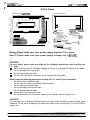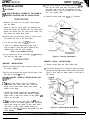
1
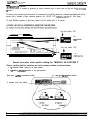
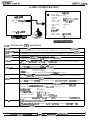
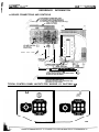
MARVEL: TM 8 @ 2000 MARVEL CHARACTERS, INC.ALL RIGHTS RESERVED.
OCAPC~M co., LTD. 2000, OCAPCOM
U.S.A.. INC. 2000 ALL RIGHTS RESERVED.
STRIDER: @MOT0 KIKAKU. WAPCOM CO.. LTD. 2000.
OCAPC~M U.S.A., INC. 2000 ALL RIGHTS RESERVED.
This
video game has been produced under the license from Marvel Characters. Inc.
OPERATORS MANUAL
WARNING
This game is for use in the United States of America and Canada.
Sales, export or operation outside of these countries may be
constructed as copyright and trademark infringements and is strictly
prohibited. Violators are subject to severe penalties and will be
prosecuted to the full extent of the law.
MVCTI 300
031300
000224 USA
THANK YOU FOR PURCHASING MARVEL VS. CAPCOM 2 TN. WE INVITE YOU TO USE
FOLLOWING MAILING ADDRESS, TELEPHONE OR FAX NUMBER FOR PARTS OR
INFORMATION CONCERNING THIS GAME:
CAPCOMa COIN-OP, INC.
ATTN: CUSTOMER SERVICE
475 OAKMEAD PARKWAY
SUNNYVALE, CA 94086
PHONE:
(408) 522-5327
FAX:
(408) 522-533 1
THE SERIAL NUMBERS OF YOUR GAME ARE LOCATED ON THE PRINTED CIRCUIT BOARDS
AS SHOWN BELOW. PLEASE HAVE THESE SERIAL NUMBERS AVAILABLE WHEN
CONTACTING US FOR SERVICE INFORMATION.
AAMA SERIAL NUMBER
PLEASE RECORD THE AAMA SERIAL NUMBER HERE:
1) AAMA SERIAL NUMBER:
PLEASE APPLY PRODUCT SERIAL NUMBER STICKER HERE:
~8COIN-0P.
,b&-iR VEL VS. CAPC0.M 2 N
INC.
TABLE OF CONTENTS
Warranty Information
ii
Safety Notices
...
III
Kit Inspection
Kit Parts List
PCB & Cables information
PCB Handling information
2
Kit Installation
Preparation
Installation
Marquee
Control Panel Overlay
Cabinet Decals
Control Panel Components
Test Switch/Service Switch
PC Boards
Wiring
Control Panel
Test Switch/Service Switch
PC Boards
:
3
l
3
3
:13
5’
4. 13
4, 13
6, 13
Game Adjustments
NAOMI SYSTEM Test Mode
Cautions on NAOMI SYSTEM Test Menu
Game Test Mode
Accessing the Menu
How to Select an Item
Menu Item Descriptions
.
Selecting monitor type (31 K or 15K)
NAOMI Converter setting (6 Button 2 Players/ 4 Button 4 Players)
Game Configuration
Game Configuration option
Sound Mode
Reference Information
Table 1: JAMMA Connections
Table 2: Test Switch/Service Switch wiring chart
Table 3: Auxiliary Cable (P/N 03-0105) connections
PCB Connector and Control location
Control Panel sample layout
11
12
12
17
17
17
Inside of back cover
Inside of back cover
-COIKOP. INC.
\
LIMITED PRODUCT WARRANTY
(APPLIES TO DOMESTIC SALES ONLY)
CAPCOMO COIN-OP, INC. (Seller), warrants only to the initial purchaser of its products, that the items
listed below are free from defects in material and workmanship under normal use and service for the
warranty periods specified:
A. Printed Circuit Boards:
B. Electronic and Mechanical Components:
Ninety (90) Days
Ninety (90) Days
No other part of Seller’s products.are warranted.
Warranty periods are effective from the initial date of shipment from seller to its authorized distributors.
Seller’s sole liability shall be, at its option, to repair or replace products which are returned to Seller
during the warranty periods specified, provided:
A. Seller is notified promptly upon discovery by buyer that stated products are defective;
9. Such products are properly packaged and then returned, prepaid to Seller’s designated plant.
This warranty does not apply to any parts damaged during shipment or handling, or due to improper
installation, usage or alteration. In no event shall Seller be liable for any anticipated profits, loss of
profits, loss of use, incidental or consequential damages or any other losses incurred by the customer
in connection with the purchase of a CAPCOMB COIN-OP, INC. product.
.WARRANTY
DISCLAIMER
EXCEPT AS SPECIFICALLY PROVIDED IN A WRIT-TEN CONTRACT BETWEEN SELLER AND
PURCHASER, THERE ARE NO OTHER WARRANTIES, EXPRESSED OR IMPLIED, INCLUDING
ANY IMPLIED WARRANTIES OF MERCHANTABILIP/ OR FITNESS FOR A PARTICULAR
PURPOSE.
IMPORTANT NOTICE
THIS SHIPMENT HAS BEEN CAREFULLY INSPECTED AND PROPERLY PACKAGED BEFORE
LEAVING THE FACTORY. WE CANNOT ASSUME RESPONSIBILITY FOR BREAKAGE THAT MAY
OCCUR DURING TRANSPORTATION OF THE GAME. IF THIS GAME IS DAMAGED UPON
RECEIPT FROM THE CARRIER, IMMEDIATELY NOTIFY THE CARRIER AND FILE A DAMAGE
REPORT.
COIN-OP.
INC.
,U4R VEL VS. ~C0.W 2 =
SAFETY NOTICES
The. following safety instructions apply to all game operators and service personnel. There are
specific warnings and cautions throughout this manual where they apply. Read this page before
preparing your game for play.
CAUTION
For your safety, please read and abide by the following instructions when handling the P.C.
-b*ad.-~~.~
~~~~
~~~
l
l
l
l
Make sure the power is off before installing the board or changing the settings of the board.
Do not damage the wiring cables.
Do not disassemble the case.
Do not touch the board, connectors or the harness with wet hands.
Please keep the following instructions to keep the P.C. board in good condition.
l
Do not block the ventilation slots.
l
Do not keep the board in extremely cold/hot places.
l
Do not drop or bump the board.
l
Do not spill any liquids on the case.
l
Do not disassemble the case.
l
Always keep the connectors clean.
l
Do not disconnect the connectors, cables, or the harness while the power is on.
WARNING.
Plug the game into a properly grounded outlet to prevent shock hazards and assure proper game
operation. Do not use a cheater plug to defeat the power cord’s grounding pin. Do not cut off the
ground pin.
EPILEPSY WARNING
A very small portion of the population has a condition which may cause them to experience epileptic
seizures or have momentary loss of consciousness when viewing certain kinds of flashing lights or
patterns that are present in our daily environment. These persons may experience seizures while
watching some kinds of television pictures or playing certain video games. People who have not had
any previous seizures may nonetheless have an undetected epileptic condition.
If you or anyone in your family has experienced symptoms linked to an epileptic condition (e.g.,
seizures or loss of awareness), immediately consult your physician before using any video games.
Parents should observe their children while they play video games. If you or your child experience
the following symptoms: dizziness, altered vision, eye or muscle twitching, involuntary movements,
loss of awareness, disorientation, or convulsions, DISCONTINUE USE IMMEDIATELY and consult
your physician.
-
~°COIN-OP.
INC.
JuRvEJc
vs
KIT INSPECTION
CHECK THAT ALL OF THE FOLLOWING PARTS HAVE BEEN SHIPPED WITH YOUR KIT.
IF Ally PARTS ARE MISSING, CONTACT YOUR DISTRIBUTOR IMMEDIATELY.
MVCTIOOO “MARVEL VS. CAPCOM 2 FULL KIT” PARTS LIST
PART NO.
DESCRIPTION
QN
MVCTI 400
MARVEL VS. CAPCOM 2 COMPLETE PCB
1
NAOMI-CONVERTER
JVS TO JAMMA CONVERTER FOR NAOMI SYSTEM
1
CBL-VGA
CABLE ASSY, D-SUB 15PIN, VGAISVGA CABLE
1
CBL-USB
CABLE ASSY, USB CABLE
1
CBL-AUDIO-ST
CABLE ASSY, STEREO AUDIO CABLE
1
CBL-POWER-NAOMI
CABLE ASSY, POWER CABLE 8PIN FOR NAOMI
1
MVCTI 110
MARQUEE, “MARVEL VS. CAPCOM 2”
1
MVCTI 300
OPERATORS MANUAL, “MARVEL VS. CAPCOM 2”
1
NOM1 300
SEGA NAOMI SERVICE MANUAL
1
AW00245-2
BUT-TON/
JOYSTICK LABEL, GENERIC
1
MVCT2520-01
1
GE1 200
GAME PLAY INSTRUCTION - TOP
“MARVEL VS. CAPCOM 2”
GAME PLAY INSTRUCTION - BOTTOM
“MARVEL VS. CAPCOM 2”
MONITOR CARD
AW00147
DECAL, CABINET SIDE
2
AW00216
CONTROL PANEL OVERLAY
1
PLO0376
MARQUEE PLEX, CLEAR, 27.0 X 9.0 X l/8”
1
GE2030
JOYSTICK, 8 WAY
2
16-6130
SWITCH, l-PLAYER START BUT-TON (WHITE)
1
16-6131
SWITCH, 2-PLAYER START BUTTON (WHITE)
1
16-0133
SWITCH, BUTTON (RED)
4
16-6134
SWITCH, BUlTON (BLUE)
4
16-0136
SWITCH, BUTON (GREEN)
4
MVCT2520-62
Note: Because of availability, your kit may contain different color of push buttons.
1
1
,’
~*COIN-OP,
.UAR VEL VS. ~4PcO.U 2 =
INC.
PCB & Cables
POWER STONE COMPLETE
PC8
NAOMI CONVERTER
US8 A-B Cable
G’
VGAJSVGA
Video Extension
--v
‘--#7-y
---,
‘-l/
/=--
Cable
Audio Extension Cable
Note 1: Please make sure your power supply supports 7A or more.
Note 2: Please make sure your power supply voltage is at +5V-C5%.
CAUTION
For your safety, please read and abide by the following instructions when handling the
P.C. board.
*
Make sure the power is off before installing the board or changing the settings of the board.
l
Do not damage the wiring cables.
0
Do not disassemble the case.
0
Do not touch the board, connectors or the harness with wet hands.
Please keep the following instructions to keep the P.C. board in good condition.
l
Do not block the ventilation slots.
l
Do not keep the board in extremely cold/hot places.
l
Do not drop or bump the board.
l
Do not spill any liquids on the case.
l
Do not disassemble the case.
a
Always keep the connectors clean.
l
Do not disconnect the connectors, cables, or the harness while the power is on.
WARNING
Plug the game into a property grounded outlet to prevent shock hazards and assure proper game
operation. Do not use a cheater plug to defeat the power cord’s grounding pin. Do not cut off the
ground pin.
MARVEL VS. G~PCOM 2 nr
(IT INSTALLATION
/! WA.RNING:
3
1AKE SURE ELECTRICAL POWER TO THE GAME IS
,FF BEFORE STARTING THE KIT INSTALLATION.
13. Peel off the backings of the 6-button and joystick decalsalign over the control panel holes, and press in place on’
the overlay (refer to the drill hole template for proper
placement). Using a knife, trim material from the center
hole of the joystick decal.
14. Install the control panel cover, figure.1.
(If required).
PREPARATION
Disconnect and remove the old printed circuit board(s)
from the cabinet.
Remove or open the control panel, and disconnect and
remove the buttons and joystick(s) from the control panel.
Remove any covering from the control panel overlay, and
then remove the control panel overlay.
Determine where any new holes should go. Center punch
any needed new holes on the control panel.
Cut out the new holes using a l-3/16” hole saw.
If there is an additional Control Panel Cover, figure 1
(such as plastic or lexan) that will be utilized cut any
additional holes using the same template.
‘Cover is not included in the kit.
Plug up unused holes with a wood dowel (l-1/8” diameter)
and sand any rough edges.
Figure 1: Overlay Installation
INSTALLATION
CABINET
IARQUEE
INSTALLATION
INSTALLATION
15. Remove monitor glass and install monitor card
Remove the marquee plexi glass, marquee overlay, and
the cabinet graphics.
Install the new marquee and replace the plexi glass. Clear
plexi glass is included In “full” kit.
ZONTROL
:igure 1)
DECAL
16. Peel-off the backing to the instruction decals and place
on both the top and bottom of the monitor card. (See
Figure 2). Also, apply the cabinet decals to both sides of
the cabinet
PANEL OVERLAY INSTALLATION (See
O.The control panel overiay in the kit is oversized to
accommodate most control panel sizes. Center the
overlay on the control panel, leaving some excess
material at the edges.
INSTRUCTION
”
1. Remove the protective backing from the overlay and
press it down on the control panel, keeping it property
aligned. Press it down firmly, smooth out any bubbles, ana
press it over the edges.
2.Trim any excess from the overlay. Place the drill hole
template on top of the overlay, aligning it with the joystick
holes. Pierce through the overlay at each control panel
hole. Then, cut away overlay material covering the
joystick and button hoies. Remove the template and clean
off the overiay.
Figure 2: Cabinet Decal Installation
RE-ASSEMBLY OF COMPONENTS
CONTROL PANEL WIRING
17. Notice that there are two white buttons. See figure 3.
The WHITE buttons are START buttons. Install the one
player button on the top left-hand side of the control
panel, and the two players button on the top right-side of
the control panel.
Control
Red Green
21. Reconnect the existing JAMMA connectors to the
control panel according to the chart in table 1 on
page 17.
l-war 1A god
the player 2 kick
22. Connect the pla,LL
u
buttons to the auxiliary cable harness as shown
in figure 6. Make the connections according to
the chart in table 2.
To *w*
Panel
Blue
Red Green
Blue
R e d Green B l u e
Red Green
Blue
NOTE: All switch wires used in this game must be wired
to the N.O. (Normally-Open) connection on the switches.
Each switch requires a ground wire on the COM.
(Common) connector and the appropriate control or switch
wire on the N.O. (Normally-Open) connector of the switch.
BUttOtIS
-3
Remning
y&
R i n g s Swwhcs
-
Figure 6: Auxiliary Cable Harness
Tg p&
TEST SWITCH WIRING
$ffl
.lY
Figure 4: Control Panel Buttons and Switches
18. Install all
as shown
immediate
buttons to
buttons to
buttons and retaining rings on the control panel
in Figure 4. Install two red buttons to the
right of each joystick, install two green
the right of the red ones, and install two blue
the right of the green ones.
23. Your cabinet may already equipped with test switch
and service switch. When installing, the test switch
and service switch, should be mounted inside the
coin door and on top of the cash box for easy access.
(See Table 3: for wiring detail)
NOTE: Test switch and service switch should be
installed for this game to access NAOMI test
menu system.
19. Install the switches on the buttons as shown in figure 4.
Orient the switches so that when a button is pressed, the
plastic contact on the switch is depressed.
20. Install the joysticks on the control panel as shown in
figure 5.
Figure 7: TestiService switch mounting
Volume adjustments must be made through the
volume control knob located on the NAOMI CONVERTER PC- board.
24.
Figure 5: Joystick installation
If you are converting a cabinet that is equipped with
CAPCOM@ Q-SOUND, you may use stereo audio
output connect to existing Q-SOUND POWER
AMPLIFIER. And set “SOUND MODE” to “Stereo”.
See “SYSTEM CONFIGURATION” for detail.
r.*
l
w -COlN-CP. INC.
.u-tR VEL VS. CAP,--:u
;’ 1’1
!, ,~, , ,
PC BOARD INSTALLATION
25. install the PCB and the NAOMI-CONVERTER to the mounting shelf.
l
Wood Screws for NAOMI-CONVERTER are not included in the kit.
PARALLEL MOUNTING
-0 mw.s” -r c- UL
PC BOARD MOUNTlNG TIPS
l
Parallel
Mounting
This mounting style is recommended for a reguial
style cabinet equipped wtth a horizontal mounting
shelf.
l
Tandem Mounting.
This mounting style could be used for cabinets
which have a vertical mounting shelf.
,/!. _ .
mA-L;..--E=ZZ---L’
.-.---,
-
TANDEM
MOUNTING
TO POWER SUPPL”, CONTROL PANEL
COlN OOOR AND TEST SWITCHES
If you are mounting in tandem make sure you havl?
enough room to access cables, connectors and
switches.
l
Stacked Mounting.
If your cabinet does not have enough room to
mount two PC Boards in parallel or Tandem
position. This mounting style may be used to Ins&II
the PC Boards.
Use large mounting brackets supplied in the kit to
mount the NAOMI-CONVERTER over the top of
the game PC Board.
We recommend mounting PC Boards in the
horizontal position for easy access and stable
operation.
m@COIN-OP,
PC
INC.
.WiR VEL VS. CdPC0.u 2 :I
.,.,.
BOARD WIRING CONNECTIONS
WARNING
Improper installation of the connector
harness (JAMMA I USBNIDEO) to the
PC board connector may cause
damage to the PC board..
30. Attach Power, US6 cable, Audio cable and Video cable to NAOMI Board.
31. Connect other end to NAOMI-COVERTER Board.
32. If you are installing the game equipped with High-Resolution monitor, connect the Video cable to the monitor.
A standard low-resolution video signal is supplied through the JAMMA connector on the
NAOMI-CONVETER, if your cabinet is not equipped with a high-resolution monitor.
The NAOMI-CONVERTER Board will not convert video signal frequency and signal level.
33. Connect the JAMMA harness connector to the edge connector on the NAOMI-CONVERTER Board.
34. If you elect to use Q-Sound Audio Amplifier or similar stereo amplifier board, connect audio cable to audio
output on the NAOMI-CONVERTER Board.
Audio volume control is located on the NAOMI-CONVERTER Board.
Sound setting and output terminal (please refer to GAME CONFIGURATION to set the SOUND MODE)
SOUND MODE
STEREO
MONAURAL
l
CONNECTOR LOCATIONS TWs-
. JAMMA CONNECTm sKE
OUTPUT TERMINAL
JAMMA HARNESS ONLY
STEREO OUT
JAMMA H A R N E S S O N L Y
STEREO OUT
Add~t”,“~l Connector
SOUND
MONAURAL
STEREO
MONAURAL
-wWlNG
DIAGRAM
~*CCWOP.
INC.
it&iR VEL VS. CAPCOM Z -
NAOMI SYSTEM TEST MODE
‘his test mode mainly allows the PC Board to be checked for accurate functioning, monitor color to be adjusted
s well as COIN ASSIGNMENT AND GAME ASSIGNMENT to be adjusted.
‘or the details of “NAOMI SYSTEM MENU”, please refer to “NAOMI SERVICE MANUAL”.
iOW TO ENTER THE TEST &MODE
Move the arrow (Cursor)
Enter to selected item
For the details of
“NAOMI SYSTEM MENU”
please refer to
“NAOMI SERVICE MANUAL”.
To enter the GAME TEST MODE, move the ” - > ” cursor to GAME TEST MODE in the NAOMI SYSTEM
.kllCNU and press the Test Button.
r
- >
SYSTEM MENU
-VERSION
--> %ZTT
SOUND TEST
C. R. T TEST
SYSTEM ASSIGNMENTS
COIN ASSIGNMENTS
BOOKKEEPING
BACKUPDATACLEAR
CLOCK SmNG
ROM BOARD TEST
GAh4ETESTh4OOE p4ARVEL vs. CAPCOM 2)
EXIT
SELECT MTH SERVICE BUlTON
\
GAME TEST MODE
INPUT TEST
GAME DATA
GAME CONFIGURATION
EXIT
PRESS Tit-% BUTTON
SELECT = 1 P UP or DOWN
START = 1P SHOT1
CAUTIONS ON NAOMI SYSTEM MENU
1) Please set the CABINET TYPE and the MONITOR TYPE of the SYSTEM ASSIGNlMENTS
menu to
“2 PLAYER(S)” and “HORIZONTAL” respectively.
This game will not function properly if above is not followed.
2) The following is the default settings of COIN ASSIGNMENTS.
t-nr;u
UVY. CH’VTF
w--i-- -TYPE
- - -
COMMON
COI-WCREDIT
co!24 CHUTE $1
COIN CHUTE $2
#12
2 COINS 1 CREDIT
2 COINS 1 CREDIT
SE-ITING
3) Please refer to the following for the SEQUENCE SETTING of the COIN ASSIGNMENTS.
SEQUENCE 1: Credits required to start the game.
SEQUENCE 2: Credits required to continue the game.
* SEQUENCE 3-8 is not available in MARVEL VS. CAPCOM 2.
* Ex) Standard setting
One(l) credit to start and continue the game.
SEQUENCE 1
SEQUENCE 2
1 CREDIT(S)
1 CREDIT(S)
t Credits required to start the game.
t Credits required to continue the game.
* Ex) 2 credits start, 1 credit continue setting
Players need 2 credits to start the game but only one credit to continue the game.
SEQUENCE 1
SEQUENCE 2
2 CREDIT(S)
1 CREDIT(S)
t Credits required to start the game.
t Credits required to continue the game.
4 ) BOOKKEEPING t/2 indicates the following:
Pl(P2) SEQ 1: The number of times the game was started from Player 1 and Player 2 each.
Pl(P2) SEQ 2: The number of times the game was continued from Player 1 and Player 2 each.
* SEQ 3-8 is not available in “MARVEL VS. CAPCO~I 2”.
W
The number of “Start” of 2P side.
The number of “Start” of 1P side.
I
Pl
Pl
SEQ 1
SEQ 2
82
36
/
The number of “Continue“ of 1P side.
/
P2
P2
SEQ 1
SEQ 2
45
15
‘\
The number of “Continue” of 2P side.
.,.I.,
I
Propnctav and confidcntirl information.
not to be disclosed or copted vtthouc the cxpreu pc- ‘on of CAPCOMO
COIN-OP. LUC.
i.,,I’s;1
,. I. .
s*COIN-OP.
,w#?vEL vs. cAPcOM2~
INC.
GAME TEST MODE
The test menu allows you to test input devices such as joysticks, buttons and coin mechs
Through the test menu you can also access the game configuration menu. where you can change the settings of the game.
The game data shows the earning-related data.
Your setting will be saved in the backup RAM. Do not turn off the power before you EXIT game test mode!
The NAOMI SYATEM MEW will appear when you EXIT GAME TEST MODE
GAx:E TEST MODE
- > INPUT TEST
GAME DATA
GAME CONFIGURATION
CONTROLS IN GAME TEST MODE
l
* Use the Jcystti and the Mlon
AS ~lluslralaa
EXIT
SELECT = 1P UP or DOWN
S T A R T = 1P SHOT1
1. TEST ,MENtJ ITELM DESCRIPTIONS
IXPUT
TESTS THE “INPUT SIGNAL” OF THE LEVER AND THE BUTTONS. WHEN THE “INPUT SIGNAL” IS
DETECTED, THE NUMBER CHANGES FROM “0” TO “1”.
.
INSIDE MPUT TEST, YOU CAN TEST UP TO TWO SERVICE BUTTONS. M CASE YOUR
CABINET HAS ONLY ONE SERVICE BL-ITON. PLEASE MAKE SURE IF THE 1P SERVICE
BUTTON FUNCTIONS PROPERLY.
(PLEASE NOTE HOWEVER. ON CERT.-\13 CiBLUETS, IT IS POSSIBLE THE NUMBER
CHANGES TO “1” ON BOTH 1P AND 2P SIDE.)
19
G.OlE DATA
SHOWS THE Ei’&NMG-RELATED DAT.4. PLE.\SE
SETTINGS FOR YOUR LOCATION.
CONFIGURATION
SETS THE GAME PLAY SETTINGS SUCH
E‘XIT
RETURNS TO NAOMI SYSTEM IMENU
Propncca~
and cowidcnutl
rnfomruoo.
USE THE INFO TO DETERMIXE THE BEST COI?.’
.A5 DIFFICC’LTY, NUMBER OF ROUNDS. TIMER ETC.
ZIOC to bc disclosed DI copled vlthout rhc express pcrm~u~e~ of CAPCOMO COIN.OP. INC.
-COIN-OP,
INC.
. 3lK MONlTbR CABINET
The NAOMI board is capable of producing a screen resolution that is three times as high as the CP-SYSTEM
II board.
To achieve the maximum performance, it is essential to install the board in a cabinet equipped with a 31K
monitor that is capable of high resolution graphics. (Ex. “BLAST CITY” “MEGALO 410” etc. from Sega)
To enjoy NAOMI’s graphics at their best, please use the cabinet with 31 K monitor.
Turn this switch “ON”
For
15K Monitor
Turn this switch “OFF”.
I
Naomi converter slide switch setting for “MARVEL VS.CAPCOM 2”
Please confirm that the switches are set in proper position as shown below.
1. “C SYNC/H/V SYNC” switch is on right position.
2. “4P 4SHOT /2P 6SHOT”
[View from JAMMA
switch is on right position.
connector side]
C SYNC/H/V SYNC select switch
4P
4SHOT I 2P 6SHOf
select switch
GAME CONFIGURATION
GAME CONF lGUR4TlON
->
GAME TEST MOOE
INPUT TEST
GAME DATA
-> G A M E CONFlGURATlON EXIT
SOUND MODE
DEMO SOUND HALF
CONTINUE
DIFFICULTY
DAMAGE LEVEL
TIMER SPEED
STEREO
OFF
ON
EASY [***4****]HARD
L O W [* 2 l *I HIGH
SLOW [* 2 * *] FAST
GAME SPEED
EVENT
JOIN-IN
DEFAULT
FREESELECT
OFF
ON
SAVF
R FYI1
I,..---...
SELECT = 1P UP or WWN
START = IP SHOT1
SELECT OPTION = 1PUPorOOWN
MODIFY SETTING = 1P LEFT or RIGHT
= 1P SHOT1 or SHOT2
DECIDE WITH
SHOT 1
GXME
CONFIGURATION ITEAM DESCRIPTIONS
iOUND MODE
)EMO SOU;YD HALF
ZONTINUE
)IFFICULTY
hM.-iGE LEVEL
TIMER SPEED
;ASlE SPEED
EVENT
JOIN-JN
DEFAULT
PLEASE SET THIS ITEM TO STEREO FOR NOR” OPERATIONS. SETTING TO “MONAURAL” WIU. MAKE YOUR
S O U N D O U T P U T M O N A U R A L . ( W H E N U S M G N A O M I C O N V E R T E R K I T . P L E A S E R E F E R TO PAGE 3.)
I F S E T T O “ O N ” , T H E A T T R A C T M O D E D E M O S O U N D P L A Y S A T H A L F V O L U M E . ( T O E N A B L E T H J S SEFl-lNG.
“ADVERTISE SOUND” MUST SET “ON”. PLEASE REFFER TO “NAOMI SYSTEM MENU” FOR DETAIL.)
TURNS ON AND OFF THE CONTINUE FEATURE.
SETS THE GAMES DJFFICULTY
LEVEL. THERE ARE 8 LEVELS TN TOT%.
A S T H E N U M B E R I N C R E A S E S . T H E GAME GETS MORE DIFFICULT.
S E T S T H E ATTACK P O W E R . T H E R E A R E 4 LEVELS I-N TOTAL.
AS THE NUMBER MCREASES, THE AT-TACK POWER MCREASES. (THUS THE AVERAGE PLAY TIME GETS
SHORTER)
SETS THE TIMER SPEED. THERE ARE 4 LEVELS IN TOTAL.
AS THE NU%fBER INCREASES. THE TJME ELAFSES QUICKER
SETS THE GAME SPEED. THE FOLLOWING ARE AVAJLABLE:
“NORMAL”:
REGULAR SETTING.
“TuRB0”:
QUICKER GAME PLAY.
“FREE SELECT”:
ALLOWS THE PLAYER TO SELECT “NORMAL” OR “TURBO”.
USE THJS FUNCTJON FOR EVENTSiTOURN4MMTS. IF SET TO ON, ONLY 1 CREDIT IS REQUIRED FOR 2 PLAYERS
“ V S . ” G A M E . HOWEVER T H E G A M E W I L L B E O V E R F O R B O T H P L A Y E R S R E G A R D L E S S O F T H E G A M E R E S U L T .
PLEASE SET THIS TO OFF FOR STANDARD OPERATIONS.
U S E D T O T U R N O N A N D O F F T H E JOM-IN FEATURE. PLEASE SET TO ON FOR STANDARD OPERATIONS.
IF YOU WlSH THE GAME SET-TJNG TO BE PLAYED BY 1 PLAYER ONLY(ADVISABLE FOR BEGJNNERS). SET TO
OFF.
RESETS ALL THE SETTINGS TO THE FACTORY DEFAULTS. (JNITLtLIZE)
NOT ONLY THE GAME CONFJGIJRATION
BUT ALSO THE SETTINGS IN NAOMI SYSTEM MENU(COlN
A S S I G N M E N T S , E T C . ) W I L L B E R E S E T T O T H E FOLLOWTNG FACTORY DEFAULTS.
ADVERTISE SOUND
.MONlTOR TYF’E
:
ON
:
COIN CHUTE TYPE
:
COIN/CREDIT SETTING :
SEQUENCE SETTING :
SAVE & EXIT
HORIZONTAL
COMMON
#12 (2 COINS 1 CREDIT)
SEQl=l (1 CREDIT TO START)
SEQZ=l (1 CREDIT TO CON-ITNUE)
FOR MORE DETAILS REGARDING THE NAO,MI SYSTEM ,M.ENU, PLEASE REFER TO THE “%GMI SERVICE
MAAX AL.”
S.&-S YOUR GA,ME CONFIGURATION zX%D COIN/SYSTEM ASSIGNMENTS AND RETURNS TO THE GAME TEST
MODE.
(m T.&ES APPRO,YI&UTELY
2 SECONDS TO SAVE THE SETl-INCS. PLEASE DO NOT I-LJRh OFF THE
POWER WHILE SAYING.)
11
Prom-ieury and con6dcaual mformation. not to be disclosed or covered
mthout
the express
pcrrnurro~
of CAf’COMO
COIN.OP.
INC.
1
.MAR VEL VS. cAPco:M 2 =
G&m CONFIGUR4TION
1
- S OUND
-
DEMO
OPTIONS
MONAURAL
MODE
SOUNDHALF
ON
OFF
NOTE:
Sound setting and output terminal (please refer to GAME CONFIGURATION to set the SOUND MODE)
SOUND MODE
STEREO
MONAURAL
OUTPUT TERMINAL
JAMMA HARNESS ONLY
STEREO OUT
JAMMA HARNESS ONLY
STEREO OUT
SOUND
MONAURAL
STEREO
MONAURAL
In case you wire both “JAMMA harness” and “Stereo Out,” the sound will only go through
“Stereo Out” and not the JAMMA harness.
@i&@@&&OIN-OP.
MARVEL
INC.
Table 1:
JAMMA
VS. CdPCOM2=
Harness Connections
SOLDER SIDE
GNn
N/C
I t-XX 3
2 PLAYER
DOWN
2 PL4YER L E F T
’
7 PI AYFR
RIGHT
Table 2:
Test Switch/Service Switch Wiring Chart
Wiring of the test bracket requires connections to the main JAMMA harness.
CONNECTS TO
SWITCH FUNCTION
TEST
SERVICE
GROUND
Table 3:
Auxiliary Cable
t W I R E C O L O R 1 CONNECTORODD 1
RED
( PLAY
RI IIF
I
PLAY
(
N/C
i N/C
t BLACK
I
) PLAYER 2 KICK
( COMMON
JAMMA
JAMMA
“15
“R”
JAMMA
“A” . “6” , ‘E” , “F” “1” , “2” , “27” OR ‘28”
(P/N 03-0105)
Connections
CONNECTOR
EVEN
1 WIRE COLOR 1
-‘COIN-OP.
INC.
MAR VEL VS.
REFERENCE
PC
INFORMATION
BOARD CONNECTIONS AND CONTROLS
STEREO
AUDIO
CABLE.
P SWITCH- === I/
/ POWER CABLE:
I
II
I!
‘* PSW2:(S&ICE
SVI
I
I,
.---
----_. - _. _
---
--- -- ___
FOR LOW-RES MONITOR:
TYPICAL CONTROL PANEL LAYOUTS FOR “MARVEL VS. CAPCOM 2 IxF’
i
GiPC0.t.f
2 rn
WARNINGS & NOTICES
WARNING
A very smash portion of the population has a condition which may cause them to experience epileptic
seizures or have momentary loss of consciousness when viewing certain kinds of flashing lights or
patterns that are present in our daily environment These persons may experience seizures while
watching some kinds of television pictures or playing certain video games. People who have not had
any previous seizures may nonetheless have an undetected epileptic condition.
if you or anyone in your family has experienced symptoms linked to an epileptic condition (e.g.
seizures or loss of awareness), immediately consult your physician before using any video games.
We recommend that parents observe their children while they play video games. If you or your child
experience the following symptoms: dizziness, altered vision, eye or muscle twitching, involuntary
movements, loss of awareness, disorientation, or convulsions, DlSCONTlNUE USE IMMEDIATELY
WARNING
Federal law provides severe civil and criminal penalties for the unauthorized reproduction,
distribution, or exhibition of copyrighted audiovisual works and video games.
The Federal Bureau of Investigation investigates allegations of criminal copyright infringement.
NOTICE
This equipment has been tested and found to comply with the iimits for a Class A digital device,
pursuant to Part 15 of the FCC Rules. These limits are designed to provide reasonable protection
against harmful interference when the equipment is operated in a commercial environment. This
equipment generates, uses, and can radiate radio frequency energy and, if not installed and used in
accordance with the instruction manual, may cause harmful interference to radio communications.
Operation of this equipment in a residential area is likely to cause harmful interference, in which case
the user will be required to correct the interference at his own expense.
NOTICE
Information in this manual is subject to change without notice. CAPCOM COIN-OP, INC. resewes the
right to make improvements in equipment function, design, or components as progress in
engineering or manufacturing methods may warrant.
NOTICE
No part of this publication may be reproduced by any mechanical, photographic, or electronic
process, or in the form of a photographic recording, nor may be transmitted, or otherwise copied for
public or private use, without permission from the publisher.
A P
W”
COIN-OP, INC.
475 Oakmead Parkway
Sunnyvale, CA 94086
Phone: (408) 774-0500
Fax: (408) 522-5331
Copyright 0 2000 CAPCOM 63 COIN-OP, INC.,
All Rights Reserved