1
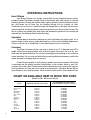
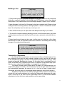
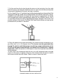
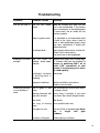
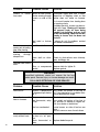
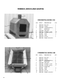
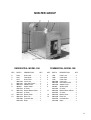
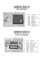
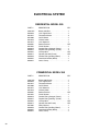
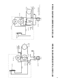
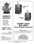
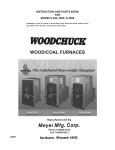
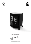
THE
BRYAN FURNACE
$10.00
RIK-MAR CORPORATION
400 Stone
Stone City
City Drive
Drive ●• Bryan,
Bryan, Texas
Texas
Phone 979-779-1616
409-779-1616
FAX 979-822-0540
409-822-0540
OWNERS MANUAL
Residential, Commercial Wood Burning Furnaces
All installations must be in accordance
with local and state codes which may
differ from this manual.
Save these instructions.
U.S. Patent 4,194,688
Canadian Patent 1,123,295
Shown With Optional Furnace Stand kit
P.N. 907-015
Thank you for choosing the Bryan Furnace for your solid fuel heating needs.
Pride, craftsmanship, and a high grade of materials insure that you have chosen a
furnace of the highest quality. This quality construction, together with our patented
outdoor installation guarantees you the safest, cleanest solid fuel heating system
available. With a minimum of maintenance, your furnace should provide you with
many years of trouble free service.
Please read through these instructions before beginning installation of your
furnace. They contain many helpful tips on installing, maintaining, and operating
your Bryan Furnace. Check with your local building officials to be in conformance
with local building, plumbing, and electrical codes. These instructions can help you
now as well as in the future and should be retained for your reference.
TRANSPORTATION
DAMAGES
Before proceeding, please inspect your furnace for any damages which may have
occurred in shipping. If you find any damage, please notify your dealer immediately. He
will take action to correct the problem.
TABLE OF CONTENTS
Operating Instructions
How It Works
Operation
Building a Fire
Temperature Adjustment
Creosote and Soot Formation and the Need for Removal
Ash Removal
Helpful Hints
Page
2
2
3
3
4
5
5
Installation Instructions
General Notes
Window or Wall Installation
Separate Duct System
Heat Pump Connection
Central Heat Connection
Special Precautions for Indoor Installation
7
7
8
10
10
11
Trouble Shooting
13
Maintenance
15
Section 10 – Parts Breakdown
10 10 1010 10 10 10 10 10 10 10 -
1
2
3
4
5
6
7
6
7
8
9
Firebox, Brick and Grates
Shelter Assemblies
Door Assemblies
Damper Box Group
Electrical Components
Residential Model 350 Wiring Diagram
Commercial Model 300 Wiring Diagram
Mount Kit Group
Chimney Parts
Furnace Stand Kit
Supplies
16
17
18
19
20
21
21
22
22
22
23
Section 20 – General Inspection and Care
20
20
20
20
20
-
Warranty
1
1
1
1
2
Periodic Inspections
Oiling Blower Motor
Adjusting Door Handles
Replacing Door Ropes
Re-Sealing Door Frame
24
24
24
24
24
Inside Back Cover
1
OPERATING INSTRUCTIONS
How It Works
Your Bryan Furnace is an airtight, natural draft furnace located inside an insulated metal shelter. The blower, located on top of the furnace, pulls cold (return) air from the
building, passes it through the shelter where it picks up heat from the combustion chamber, and forces the air back into the building through the hot (supply) air duct.
Combustion air for the fire is pulled through the damper box on the door into the combustion chamber and exhaust gases leave through the flue on the top of the furnace. The
two air systems are sealed from each other and combustion gases will not normally be
released into the building (See Trouble Shooting).
Operation
Please keep in mind when operating any solid fuel heater that unlike a gas, oil, or
electric heater, the fire cannot simply be turned on or off to control building temperature.
Once a solid fuel fire is established, it must be allowed to burn to conclusion.
Firewood
The Bryan Furnace will burn any type of wood up to 12” in diameter and 30” in
length. Wood can be burned either with or without grates. Store your fuel in a dry, covered area with good ventilation. Do not stack wood against the building as this invites an
insect infestation. Do not store fuel within the furnace installation clearances or within the
space required for charging and ash removal.
Firewood varies greatly in quality due to species and moisture content. Wood that
is seasoned and dry greatly improves the efficiency of the furnace. Wood of over 20%
moisture will not burn well. Pine and some other softwoods burn very quickly with high creosote production and very few coals. If pine must be burned, it should be burned with an
open damper in very small quantities. These woods are best used to start hardwood fires.
CHART ON AVAILABLE HEAT IN WOOD PER CORD
(Based on 20% Moisture In Wood)
TYPE
Hickory
Maple (Hard)
Beech
Oak (White)
Oak (Red)
Birch (Yellow)
Elm
Tamarack
Maple (Sot)
Cherry
Ash
Spruce
Hemlock
Pine(White)
Aspen
Basswood
2
AVERAGE WEIGHT PER CORD
3,595
3,075
3,240
3,750
3,240
3,000
2,750
2,500
2,500
2,550
2,950
2,100
2,100
1,800
1,900
1,900
Ibs.
Ibs.
Ibs.
Ibs.
Ibs.
Ibs.
Ibs.
Ibs.
Ibs.
Ibs.
Ibs.
Ibs.
Ibs.
Ibs.
Ibs.
Ibs.
APPROXIMATE BTU AVAILABLE
IN AN AIR-DRIED CORD OF WOOD
30,600,000
29,000,000
27,800,000
27,700,000
26,300,000
26,200,000
24,500,000
24,010,000
24,000,000
35,500,000
22,600,000
18,100,000
17,910,000
17,900,000
17,700,000
17,101,000
Building a Fire
CAUTION
Never use chemicals or fluids to start or
freshen-up a fire. Do not burn garbage,
gasoline, naphtha, engine oil or any
other fuel not approved with this unit.
1. Place several pieces of crumpled newspaper on the grate, crisscross the newspaper
balls with a couple of handfuls of dry kindling wood 3/4” thickness or less, then several
small pieces of dry firewood. Be sure the smokepipe damper is open if one is installed.
2. Ignite the paper. It will take 5 to 10 minutes for the fire to establish itself. Once you have
some good red hot burning embers, add larger pieces of wood. All installations are different. You will quickly learn the best way to start your unit.
3. After 30- 40 minutes you can adjust the intake damper according to your needs.
4. To reload the furnace containing existing hot coals, rake the coals evenly, add a few
smaller pieces over the coals. then load up. Do not use an automatic stoker with this furnace.
5. Never leave the ash clean-out door open to allow more air to the fire as this allows
extreme heat to enter the automatic draft control located on the loading door causing
damage to the solenoid and thermostat.
CAUTION
The handle on the ash door can become extremely
hot, use care when handling. The ash door must be
securely closed whenever the furnace is unattended to prevent dangerous overheating.
Temperature Adjustment
A solid fuel fire burns cleanest in an environment with an unlimited supply of oxygen. Allowing a fire to burn this way, however, produces a short, very hot fire with most
of the released heat going up the flue and the extreme temperatures causing a safety
hazard and possibly damaging the furnace. On the other hand, a smothered fire produces an extremely long, smoldering burn which is inefficient and produces large quantities of soot or creosote with the danger of a clogged flue or stack fire.
The Bryan Furnace controls these factors by means of a thermostatically controlled intake damper mounted on the furnace door. As the fire gets hotter, the thermostat automatically decreases the amount of air to the fire to keep it under control.
Conversely, as the fire cools off, the damper begins opening to allow the fire more air.
Temperature adjustments are made by turning the knob on the door clockwise for
a hotter fire, and counter clockwise for a cooler fire. Make small adjustments with reference to the arrow on the knob and the hotter decal. Wait 15 to 30 minutes between
adjustments to allow the fire to reach equilibrium at the new setting.
3
CAUTION
The damper control mechanism
must not be altered for any reason.
*An additional safety system is built into your Bryan Furnace to control an
overtemperature condition. This system consists of a solenoid mounted in a separate
compartment above the damper box on the door. If electrical power to the furnace is
interrupted, the solenoid will automatically close the damper. Also, if air temperature in
the furnace reaches approximately 220° F, the solenoid will shut the damper and it will
not re-open until the furnace has cooled to approximately 160° F. Do not use the
overtemperature safety system to control the fire with a maximum damper setting.
This causes an extremely inefficient burn with the fire smothered about half of the
time. Maximum heat output is achieved by setting the damper so that temperatures do not quite reach an overtemperature condition.
NOTE: The solenoid will produce a low buzzing sound and the cover will be warm as long
as it is receiving electrical power. The noise will cease if the solenoid is closing the
damper due to either a power failure or over-temperature. If the solenod produces a loud
chatter, unplug the furnace immediately and see the trouble shooting guide.
CAUTION
Never operate your furnace so that any
portion becomes red hot. This is dangerous
as well as damaging to the furnace.
Creosote and Soot Formation and the Need for Removal
When wood is burned slowly, it produces tar and other organic vapors, which combine with expelled moisture to form creosote (soot with coal burning). The creosote
vapors condense in the relatively cool chimney flue of a slow-burning fire. As a result,
creosote residue accumulates on the flue lining. When ignited, this creosote makes an
extremely hot fire.
The chimney connector and chimney should be inspected at least twice monthly
during the heating season to determine if a creosote build-up has occurred.
If creosote has accumulated, it should be removed to reduce the risk of a chimney fire. If you clean your own chimney and stove pipe, we recommend purchasing the
equipment professionals use. Wire brushes are available in enough sizes and shapes to
be a snug fit inside any common flue.
NOTE: Establish a routine for the storage of fuel, care of the unit and firing techniques.
Check daily for creosote build-up until experience shows how often cleaning is necessary. Be aware that the hotter the fire, the less creosote is deposited and weekly cleanings may be necessary in mild weather even though monthly cleanings may be enough
in the coldest months. Have a clearly understood plan to handle a chimney fire.
* laboratory listed furnaces only
4
CAUTION
In the event of a chimney fire:
1. Close all air inlets and doors on the furnace.
2. Call the fire department.
3. Leave the building safely.
Ash Removal
The ash door can be opened slightly for a few seconds before servicing to allow
smoke to clear. Ashes should be removed frequently.
1. The ash door should not be opened with a full load of burning wood a this allows
excess combustion air to enter the chamber and can cause over heating .
2. After Unit has cooled down, open ash door, remove the ash pan using protective
gloves and place ashes in acceptable noncombustible container.
3. Do not leave the ash door open while emptying ashes as this allows uncontrolled combustion air to enter fire chamber and can cause overheating.
CAUTION
Ashes should be placed in a metal container with a tight
fitting lid. The closed container of ashes should be placed
on a noncombustible floor or on the ground, well away
from all combustible materials, pending final disposal. If
the ashes are disposed, of by burial in soil or otherwise
locally dispersed, they should be retained in the closed
container until all cinders have thoroughly cooled.
Helpful Hints
A small hot fire is more efficient and safer than a large smoldering one. During relatively warm weather, add only enough wood so that the fire will burn out in a desired
time. If the building becomes too hot, simply open a window. Do not unplug the furnace
or block the furnace air.
As your fire burns down, the fan will begin to cycle on and off as it moves the heated air out and the fan control thermostat is cooled. If you desire to run the fan below the
thermostat temperature range (+90° ), turn the thermostat override switch (on the bottom
of the fan box) to the “on” position. This will cause the fan to run continuously
whether there is heat in the furnace or not.
After 7 days of 8 to 10 hour burns, open the damper and allow the fire to burn hot
for 15 to 20 minutes while in attendance. This will help to minimize creosote or soot buildup.
Combustion air must be available above the fuel bed. Try to stack logs so that air
can circulate between them.
Loading and ash doors must be kept tightly closed and gaskets in good condition.
Inspect the furnace in the dark for light showing around the door. Door gaskets need to
be replaced every year or so.
A small portable generator of sufficient amperage can be used to operate the furnace
during an extended power outage. Do not operate this furnace without electrical power.
5
6
INSTALLATION INSTRUCTIONS
Please read completely before starting.
NOTICE TO OUR CUSTOMERS: Your Bryan Furnace is absolutely the safest, cleanest
solid fuel burning system available. Your furnace has been assembled from the finest
materials available by skilled craftsmen under the supervision of a strict quality control
program. Bryan Furnace Works, however, has no control over the handling of your furnace during shipment or installation. The possibility does exist, however remote, that a
broken seal will allow some smoke or fumes into the home. If the possibility of smoke
or fumes in the home is absolutely unacceptable, do not install this furnace. Keep
in mind that smoke in the home is a certainty with a fireplace or indoor heater.
WARNING
The installation of this unit must comply with state
and local requirements and be inspected by the
state or local building inspector, if required. Only
laboratory listed units can be installed indoors.
General Notes
The air from a solid fuel appliance is considerably hotter than from gas, oil or electric furnaces. Do not connect this furnace to anything other than metal ductwork.
Both hot and cold air ducts should be insulated outdoors. In addition, the hot air
duct should be insulated for its entire length. There should be a minimum of 1 “ of
insulation between the hot air duct and any flammable surface.
Your furnace has been tested to determine the minimum safe clearances to combustible materials. The clearances listed below should be adhered to strictly.
Sides of furnace
Rear of furnace
Top of furnace
Front of furnace
Flue pipe (single wall connector to
to chimney) if used
Ducting
8”
16”
24”
48”
18”
6” for first 16” from rear of unit, then 2”
Do not connect the Bryan Furnace to a chimney serving another appliance.
If the furnace is placed on a flammable surface, the floor must be protected by a
fireproof millboard or equivalent. The fireproofing must extend under the furnace and at
least 16” in front of and 8” either side of the fuel loading door.
Pull return air from the same area where supply air is being delivered. Do not pull
return air from a small or closed area where another heating appliance is located.
The resulting partial vacuum could cause the other appliance to malfunction.
Do not install the hot air inlet directly below a flammable or heat sensitive material (drapes, blinds, plastic, etc.) or those objects can be damaged by rising heat.
7
Window or Wall Installation
Tools Needed: Drill with 1/8” bit, metal cutting shears, screwdriver, silicone caulking.
ALL parts for installation are provided except the exhaust stack and rain cap. Additional
sheet metal work for nonstandard installations can be done at any sheet metal shop.
1. After uncrating, remove all of the parts from inside the furnace, being careful not to
bend or damage the sheet metal.
2. Mount the furnace door with the attached pins.
3. If the face plate is to be painted, it is best to do this before installation. With the grill
off, mask the cord, wipe the metal with vinegar or other weak acid, and spray paint when
dry. Use a high temperature resistant paint to avoid a fire hazard.
4. Window Installation - Cut the face plate to size to completely fill the window. The plate
can be cut at one or both ends to center the grill as desired. Cutting must be done carefully and the plate should be left long enough so that it will slip into the window frame and
the window can then be closed against it to form a seal. Place the strips of insulation provided between the window frame and the face plate to seal and insulate. If the plate is
installed vertically, insure that the return air side (with the wire) is on the bottom.
Vertical Opening
Horizontal Opening
5. Wall Installation - Cut a 14” x 28” opening through the wall (either vertically or horizontally) and line it with 1” fiberglass insulation (provided). Cut the face plate 2” from the duct
box on either end (see drawing below). Push the duct box through the wall from the inside
and fasten the face plate to the wall. If the plate is installed vertically, insure that the return
air side (with the wire) is on the bottom. Slip the rectangular cover plate over the ducts from
the outside and fasten it to the wall. Caulk any openings. The face plate can reach temperatures of over 200°F. If it is mounted on a surface which can be damaged by
these temperatures, place 1/4” ceramic spacers between the face plate and the wall.
6. Decide which way you want the door on the furnace to face. You can position the furnace with the door facing left or right or away from the wall. Position the furnace on
bricks, a concrete base or optional furnace stand.
8
7. Pull the cord from the fan box through the return air duct and plug it into the outlet
behind the grill on the face plate. Attach the return air duct to the fan box and face plate
using screws. Weatherproof the joints with tape or caulking.
8. Use a listed 6” Class “A” residential type building heating appliance chimney.Metal-Fab
Temp/guard 2100 deg. double wall insulated chimney with stainless steel liner is recommended for best performance and longest life. Your furnace is equipped with a 6” double
wall insulated starter section manufactured by Metal-Fab, Inc of Wichita, Kansas. Use of
an unsuitable chimney can lead to degraded performance, damage to the furnace, and
possible voiding of the warranty. The Metal Fab Temp/Guard chimney and cap may be
purchased from you dealer or distributor.
9. Plug in the electrical cord inside the building. The furnace must be connected to a single outlet circuit or to a 20 Ampere circuit. The furnace must be grounded either
through The electric cord (third prong) or by driving a copper coated steel rod six
(6) feet into the ground and attaching it to the base of the furnace with a 14 gauge
copper wire. Check the operation of the damper to insure that it operates freely and can
close completely.
10. Start a fire in the furnace and allow the fan to run until smoke and fumes no longer
come out of the warm air opening at the rear of the furnace. Attach the warm air duct to
the furnace and duct box with screws. Check for warm air leaks and caulk.
STANDARD WINDOW OR WALL INSTALLATION
9
Separate Duct System
Observe the general rules and the applicable parts under window-wall installation.
If possible, run your duct work under the floor to deliver heat at floor level. With the residential model furnace, avoid over fifty (50) feet of duct work or air delivery will be unsatisfactory. With any furnace, the more turns and branches in the ducting, the less air will
be delivered. Avoid 90° elbows
Heat Pump Connection
This installation should be made by a qualified installer.
Observe the general rules and the applicable parts under window-wall installation.
Install separate turn air duct to the building… the heat pump. Tap into the hot air duct with
an elbow or at an angle so that the hot air from the Bryan Furnace is delivered downstream. A plastic joint in the heat pump ductwork will have to be removed, if present. The
heat pump can be turned off at the breaker box if desired. Any obstructions in the heat
pump duct must be removed before using it as an air conditioner.
Central Heat Connection
10
This installation should be made by a qualified installer.
Observe the general rules and the applicable parts under window-wall installation.
Run a return air duct separate from the return air for the central furnace or the hot air from
the Bryan Furnace may try to short circuit back through the central furnace. Attach the hot
air duct to the hot air plenum of the central furnace with an elbow or at an angle so that
hot air from the Bryan Furnace is delivered downstream. Insure that hot air from the Bryan
Furnace is not delivered so that it passes through an air conditioner coil. Obstructions in
the plenum may have to be moved to operate a central air conditioner.
CENTRAL HEAT CONNECTION
For a down draft furnace, such as in a mobile home, do not attach the hot duct
from the Bryan Furnace to the hot air plenum, or the heat will rise through the central furnace
instead of going down the duct work. Split the hot air supply from the Bryan Furnace with
a “Y” and install one branch into each of the hot air ducts, again pointed downstream.
DOWNDRAFT FURNACE
Special Precautions for Indoor Installations (laboratory listed units
only)
Chimney
The greatest hazard to a solid fuel furnace is an unsuitable chimney. If an existing
chimney is to be used, insure that it is a “class A” factory built chimney. Have the chimney inspected to insure that it is clean and in good condition. Of special danger are
class “B” aluminum gas vents which may already be installed and should never be
used. If a new chimney is to be installed, the chimney dealer will be able to provide
advice and the necessary parts. Particular attention should be paid to the point where
the flue passes through a wall or ceiling. This penetration should always be made with
insulated pipe and the proper accessories. The top of the chimney should be at least
three (3) feet higher than the roof at the point of exit. With pitched roofs, the top of the
chimney must be at least two (2) feet higher than any point on the roof within ten (10)
feet of the chimney. Check with your local Building Inspector for local building code compliances. Never use a masonry chimney as they can clog or collect deposits and may
cause chimney fire.
11
12
Troubleshooting
Problem
Possible Cause
Solution
Fire will not stay lit. Fire not well estab- Keep the furnace door open until the
lished.
fire is well established. If the access
door is closed prior to the development
of some coals, the air intake will not
function properly.
Damp or green wood.
It is advisable to use seasoned wood
to build a fire. Later, when a bed of
coals is well established, green wood
may burn satisfactorily if mixed with
seasoned wood.
Insufficient draft.
Open damper thermostat for a hotter fire.
Check flue for obstructions.
Flue may have to be lengthened.
Building is not warm Unit too small for Replace with larger until or have reguenough.
building - check speci- lar furnace help heat the building. If
fications.
furnace is producing 200°F air at
outlet (150° commercial or coal
burner) it is performing at or above
Its rated capacity.
Insufficient insulation Reinsulate.
i n bu i l d i n g - h e a t i s
escaping.
lmproper installation.
Excessive creosote
or soot buildup in
stack.
Review installation instructions.
Check for hot air leaks.
Use of green or wet Use seasoned dry wood or burn smallwood.
er charges hotter.
Burning softwoods with Avoid using if possible. If you must
high resin content.
burn them, burn small charges hotter.
Poor draft.
See above.
Too long of burning Burn smaller-hotter fires.
times.
Flue pipe too cool.
Too cool of fire or improper pipe. Never
use
a
single
wall
pipe
outdoors.
Air leaks in flue pipe.
Check pipe top to bottom.
13
Problem
Possible Cause
Solution
fumes Normal for new furnace. Disconnect supply duct until it clears.
Smoke entering through Reposition of lengthen stack so that
louvers on side of fan smoke does not settle on furnace.
box.
Try to avoid smoke from loading door
by opening slowly.
If problem persists, louvers can be covered with tape. Closing off louvers
will prevent fresh air from being
brought into building and can lead
to fan overheating. Observe furnace
closely to insure that fan does not
shut off.
Bad weld or broken If above do not fix problem, contact
seal.
your dealer immediately.
See above.
Excessive
smoke Insufficient draft.
coming out of loading
door when loading.
See above.
Puffs of smoke Insufficient draft.
coming
through
damper box.
Down draft on chim- Check for obstructions near chimney,
ney.
trees, buildings, etc.
Replace gasket.
Improper seal around Torn or loose gasket.
door.
Worn or compressed Reverse latch for tighter fit.
gasket.
Replace gasket.
Smoke or
from vent.
WARNING
Unqualified individuals should not remove the fan box
access panel. Personal injury or furnace damage can result.
CALL AN ELECTRICIAN OR YOUR DEALER!
Problem
Possible Cause
Normal if temperature
in furnace drops below
90° F.
Fan will not run with No power to furnace.
heat in furnace.
Bad thermostat, relay,
or fan.
Solution
Turn switch on bottom of fan box to
“on” if you desire fan to run below thermostat temperature range.
Check electrical supply.
Turn switch on bottom of fan box to
“on” position to attempt to regain fan.
Call your dealer or electrician.
Fan has overheated.
Insure louvers on side of fan box are
clear.
Fan will come on once it cools down.
Fan runs continu- Switch on bottom of Move switch to “auto” position.
ousIy without heat. fan box is in “on” position.
Stuck thermostat or Replace defective parts.
relay.
Fan cuts off.
14
Problem
Possible Cause
Solution
Damper will not Mechanism is jammed Check for cause through hole in door
open / solenoid on or has become discon- behind damper box.
nected.
door is buzzing.
*Damper will not Furnace
open / solenoid on power.
door is not buzzing.
has
lost Check electrical supply.
Furnace has overheat- Limit switch will close damper if outlet
ed.
air exceeds 220°F. Set your damper for
a cooler fire.
Circuit breaker on bot- Push in button after insuring that
tom of fan box has damper mechanism is not jammed. If
popped.
breaker continues to pop, call your
dealer or electrician.
Transformer, solenoid, Call your dealer or an electrician.
or wiring is bad.
*laboratory listed furnaces only
Additional References
For further information on using your heater safely, obtain a copy to the National
Fire Protection Association publication “Using Coal and Wood Stoves Safely”, NFPA No.
HS-8- 1974. The address of the NFPA is Battery March Park, Quincy, Ma 02269.
Some additional suggested readings are:
Havens, David, The Woodburner’s Handbook, Brunswick, Maine, Harpswell Press, 1973.
Shelton, Jay and Shapiro, Andrew B., The Woodburner’s Encyclopedia, Waitsfield,
Vermont Crossroads Press, 1976.
Gay, Larry, The Complete Book of Heating with Wood, Charlotte, Vermont, Garden Way
Publishing, 1974.
Self, Charles, Wood Heating Handbook, Blue Ridge Summit, Pennsylvania, Tab Books,
1977.
Maintenance
Unit - Keep the unit itself clean for extended life. Promptly paint over any rust spots which
may appear on the galvanized surfaces with cold galvanizing spray paint available at
hardware stores, heating & cooling supply stores, etc.
Fan - Warning: always disconnect the electrical supply to the furnace before
exposing the fan for maintenance. Every six months, remove the fan box access panel
and lightly oil the motor through the two oil holes on the top side of the motor. Periodically
remove the return duct at the fan box and clean the squirrel cage to maintain fan efficiency.
Parts
Contact your dealer or the factory for parts. When ordering, simply state the model
furnace and part desired. Defective parts being replaced under warranty must be
returned to the dealer or factory before new parts will be issued.
15
FIREBOX, BRICK AND GRATES
RESIDENTIAL MODEL 350
KEY
PART #
DESCRIPTION
1
2
3
960-1370
960-1450
950-1304
1527
950-1409
950-1554
950-1400
904-048
960-1562
960-1453
960-1565
Base Pan . . . . . . . . . . . .1
Firebox . . . . . . . . . . . . .1
Firebox Stack Assy . . . .1
Baffle Plate . . . . . . . . . .1
Rear Brick . . . . . . . . . . .1
Fire Brick, 1” split . . . . .16
Fire Brick, spt tap . . . . . .9
Grate . . . . . . . . . . . . . . .3
Poker . . . . . . . . . . . . . . .1
Ash Pan . . . . . . . . . . . . .1
Support, Grate S.S.
4
5
6
8
9
10
11
QTY
COMMERCIAL MODEL 300
KEY
PART #
DESCRIPTION
1
2
3
960-1370
960-1455
950-1304
1527
950-1409
950-1401
950-1400
950-1419
904-048
960-1562
960-1453
960-1565
Base Pan . . . . . . . . . . . .1
Firebox . . . . . . . . . . . . .1
Firebox Stack Assy . . . .1
Baffle Plate . . . . . . . . . .1
Rear Brick . . . . . . . . . . .1
Fire Brick, 1” split . . . . .16
Fire Brick, spt tap . . . . . .9
Bridge Brick . . . . . . . . . .
Grate . . . . . . . . . . . . . . .3
Poker . . . . . . . . . . . . . . .1
Ash Pan . . . . . . . . . . . . .1
Support, Grate S.S.
4
5
6
7
8
9
10
11
16
QTY
SHELTER GROUP
COMMERCIAL MODEL 300
RESIDENTIAL MODEL 350
KEY
PART #
DESCRIPTION
3
4
5
1420
1422
1415
960-1558
960-1452
960-1376
904-037
950-1324
960-1559
950-1325
960-1549
960-1370
950-1380
950-1350
Outer Liner . . . . . . . .
Outer Back . . . . . . . .
Outer Front . . . . . . .
Inner Liner . . . . . . . .
Galv. Door Frame . . .
Adapter Plate . . . . . .
Starter Collar . . . . . .
8” Collar . . . . . . . . . .
Blower Mount w/Duct
3” Collar . . . . . . . . . .
Blower Cover . . . . . .
Base Pan . . . . . . . . .
Insulation Set . . . . . .
Rope . . . . . . . . . . . .
7
8
9
11
13
14
.
.
.
.
.
.
.
.
.
.
.
.
.
.
QTY
KEY
PART #
DESCRIPTION
.
.
.
.
.
.
.
.
.
.
.
.
.
.
3
4
5
1501
1503
1576
960-1456
960-1452
960-1376
904-037
950-1324
960-1559
950-1325
960-1549
960-1370
950-1542
950-1350
Outer Liner . . . . . . . .
Outer Back . . . . . . . .
Outer Front . . . . . . .
Inner Liner . . . . . . . .
Galv. Door Frame . . .
Adapter Plate . . . . . .
Starter Collar . . . . . .
8” Collar . . . . . . . . . .
Blower Mount w/Duct
3” Collar . . . . . . . . . .
Blower Cover . . . . . .
Base Pan . . . . . . . . .
Insulation Set . . . . . .
Rope . . . . . . . . . . . .
.1
.1
.1
.1
.1
.1
.1
.1
.1
.1
.1
.1
.1
.1
7
8
9
11
13
14
QTY
.
.
.
.
.
.
.
.
.
.
.
.
.
.
.
.
.
.
.
.
.
.
.
.
.
.
.
.
.1
.1
.1
.1
.1
.1
.1
.1
.1
.1
.1
.1
.1
.1
17
COMMERCIAL MODEL 300
RESIDENTIAL MODEL 350
Door Assemblies
KEY
PART #
DESCRIPTION
QTY
1
2
3
4
5
6
7
8
904-039
904-038
960-1349
904-073
904-041
103-015
103-024
111-015
950-1350
908-001
960-1418
Door Frame, Cast . . . .
Door, Cast . . . . . . . . .
Door Handle Assembly
Wire Grip . . . . . . . . . .
Door Catch . . . . . . . .
Lock Washer . . . . . . .
Lock Nut . . . . . . . . . .
Door Hinge Rivet . . . .
Door Rope . . . . . . . . .
Door Glue, 3 oz . . . . .
Damper Box Assembly
See Page 21
.
.
.
.
.
.
.
.
.
.
.
COMMERCIAL MODEL 300
RESIDENTIAL MODEL 350
Ash Door Assemblies
KEY
PART #
DESCRIPTION
12
13
14
15
904-042
102-012
904-043
950-1351
908-001
960-1349
904-073
904-041
103-015
103-024
101-001
Ash Door . . . . . . . . . . .
Hinge Pin, Ash Door . .
Frame, Ash Door . . . . .
Ash Door Rope . . . . . .
Door Glue, 3 oz . . . . . .
Door Handle Assembly .
Wire Grip . . . . . . . . . . .
Door Catch . . . . . . . . .
Lock Washer . . . . . . . .
Lock Nut . . . . . . . . . . .
Screw, Frame Mounting
17
18
19
20
21
22
18
QTY
.1
.1
.1
.1
.1
.1
.1
.1
.1
.1
.8
.1
.1
.1
.1
.1
.1
.1
.2
.1
.1
.1
COMMERCIAL MODEL 300
RESIDENTIAL MODEL 350
Damper Box
KEY
PART #
DESCRIPTION
QTY
2
3
4
5
6
7
8
9
10
11
12
13
14
15
960-1413
960-1418
903-044
102-017
705-016
1541
705-017
1335
102-008
102-021
102-011
801-068
607-012
1533
950-1417
111-006
Damper Box Assembly Comp.
Damper Knob . . . . . . . . . . . .
1/4” Flat Washer . . . . . . . . . .
Bi-Metal Damper Spring . . . . .
Anti-Rotation Bracket . . . . . . .
Damper Spring . . . . . . . . . . .
Damper Chain . . . . . . . . . . . .
Bolt, 1/4” x 2 1/2” HHCS . . . .
1/4” Hex Nut . . . . . . . . . . . . .
1/4” Lock Nut . . . . . . . . . . . . .
Damper Decal . . . . . . . . . . . .
115V Damper Solenoid . . . . .
Solenoid Cover . . . . . . . . . . .
Solenoid Cable Assembly . . .
Cotter Pin . . . . . . . . . . . . . . .
.1
.1
.4
.1
.1
.1
.1
.2
.1
.1
.1
.1
.1
.1
.1
KEY
PART #
DESCRIPTION . . . . . . . . . . .QTY
16
17
18
19
20
21
22
23
24
25
26
1347
603-023
903-020
1539
950-1426
960-1379
1534
903-017
1577
1346
101-002
908-001
111-016
101-011
101-015
Solenoid Link Wire . . . . . . . . .
Conduit Fitting, 90 Deg. Mtl. . .
1/8” x 1/2” F/G Sealing Gask .
Heat Baffle . . . . . . . . . . . . . .
Insulation Insert . . . . . . . . . . .
Damper Box . . . . . . . . . . . . .
Solenoid Box Base . . . . . . . .
Spacer Insulation . . . . . . . . . .
Expanded Metal Intake . . . . .
Damper Pivot Rod . . . . . . . . .
#10 x 5/8 Tek Screws . . . . . . .
Door Glue, 2 oz . . . . . . . . . . .
l/8” Pop Rivets . . . . . . . . . . . .
#10 x 3/8” Tek Screw Solenoid
3/16” Flat Washer . . . . . . . . .
.1
.1
.1
.1
.1
.1
.1
.1
.1
.1
.4
.1
.6
.1
.2
19
ELECTRICAL SYSTEM
RESIDENTIAL MODEL 350
PART #
DESCRIPTION
QTY
960-1557
604-023
601-021
601-006
601-016
607-012
603-007
601-025
603-013
603-012
604-022
603-011
603-023
603-022
603-021
Blower, 350 Res. . . . . . . . . . . . . . . . . . . .1
115V Pigtail Cord . . . . . . . . . . . . . . . . . . .1
Thermostat Button . . . . . . . . . . . . . . . . . .4
On/Off Switch . . . . . . . . . . . . . . . . . . . . .1
Hi-Limit Switch . . . . . . . . . . . . . . . . . . . . .1
115V Solenoid . . . . . . . . . . . . . . . . . . . . .1
Double Terminal . . . . . . . . . . . . . . . . . .A/R
Circuit Breaker . . . . . . . . . . . . . . . . . . . . .1
Conduit Fitting, Straight (Plastic) . . . . . . .1
Conduit Fitting, 90 Deg. (Plastic) . . . . . . .2
Hi-Temp Wire . . . . . . . . . . . . . . . . . . . . .A/R
Liquatite Conduit (Plastic) . . . . . . . . . . .A/R
Conduit Fitting 90 Deg. (Metal) . . . . . . . . .2
Greenfield Conduit (Metal) . . . . . . . . . . . .1
Loom, Clamp . . . . . . . . . . . . . . . . . . . . . .1
COMMERCIAL MODEL 350
20
PART #
DESCRIPTION
QTY
960-1547
604-023
601-021
601-006
607-012
601-016
603-007
601-025
603-013
603-012
604-022
603-011
607-002
603-023
603-022
603-021
Blower, 300 Comm. . . . . . . . . . . . . . . . . .1
115V Pigtail Cord . . . . . . . . . . . . . . . . . . .1
Thermostat Button . . . . . . . . . . . . . . . . . .1
On/Off Switch . . . . . . . . . . . . . . . . . . . . .1
115V Solenoid . . . . . . . . . . . . . . . . . . . . .1
Hi-Limit Switch . . . . . . . . . . . . . . . . . . . . .1
Double Terminal . . . . . . . . . . . . . . . . . . .A/R
Circuit Breaker . . . . . . . . . . . . . . . . . . . . .1
Conduit Fitting, Straight (Plastic) . . . . . . .1
Conduit Fitting, 90 Deg. (Plastic) . . . . . . .1
Hi-Temp Wire . . . . . . . . . . . . . . . . . . . . .A/R
Liquatite Conduit Plastic) . . . . . . . . . . . .A/R
Relay, Mercury . . . . . . . . . . . . . . . . . . . . .1
Conduit Fitting 90 Deg. (Metal) . . . . . . . . .2
Greenfield Conduit (Metal) . . . . . . . . . . . .1
Loom, Clamp . . . . . . . . . . . . . . . . . . . . . .1
WIRING DIAGRAM-COMMERCIAL MODEL 300
WIRING DIAGRAM-RESIDENTIAL MODEL 350
21
MOUNT KIT
KEY
PART #
DESCRIPTION
1
2
3
4
960-1550
601-024
604-023
603-015
603-008
950-1532
904-047
603-025
603-026
101-002
Mount. . . . . . . . . . . .
115V Outlet . . . . . . .
16/3 SJO Cord . . . . .
Strain Bushing . . . . .
Wire Terminal . . . . .
Flashing Plate . . . . .
24” x 12” Grille . . . . .
J-Box . . . . . . . . . . . .
J-Box Cover Plate . .
#10 x 5/8” Tek Screw
6
7
8
9
10
QTY
.
.
.
.
.
.
.
.
.
.
.
.
.
.
.
.
.
.
.
.
.
.
.
.
.
.
.
.
.
.
.
.
.
.
.
.
.
.
.
.
.
.
.
.
.
.
.
.
.
.
.
.
.
.
.
.
.
.
.
.
.
.
.
.
.
.
.
.
.
.
.1
.1
.1
.2
.3
.1
.1
.1
.1
.6
CHIMNEY PARTS GROUP
904-044
904-049
904-050
904-054
6” Stack Band
6” x 48” Double Wall Chimney Pipe
6” Spark Arrestor Cap
6” x 24” Double Wall Chimney Pipe
(Non-Stock Item)
FURNACE STAND KIT
970-1554
22
Furnace Stand Kit
SUPPLIES
PART #
DESCRIPTION
101-001
101-002
111-016
908-014
908-013
908-001
908-002
908-003
903-017
921-022
921-015
603-011
903-020
907-015
907-016
907-017
909-003
909-004
903-018
904-075
903-040
903-041
1/4” X 1” Self Drilling Screw, ea.
#10 x 5/8” Self Drilling Screw, ea.
18” Pop Rivet
Refractory Cement, 1 qt.
Silicone Sealer, 10.3 oz Tube
Door Gasket Cement, 3 oz.
Door Gasket Cement, 11 oz.
Refractory Cement, 1 pint
Door Rope, Ft. Bulk
Cold Spray Galvanizing Compound, Spray
Paint, Black Spray, Hi-Heat, 16 oz.
3/8” Liquatite Conduit, fr. (4’ min.)
Gasket Tape, ft.
Operator & Parts Manual, Bryan Furnace
Brochure, Bryan Furnace
Metal-Fab Brochure
Pallet, Universal
Box, Universal
Insulation, sq. ft.
10” x 54” Flex Duct, 2 per unit
10” UV Sheath, Pre-cut, 2 per unit
10” UV Sheath, Bulk
23
GENERAL INSPECTION AND CARE FOR YOUR FURNACE
Periodic inspections need to made on your furnace. Inspect for loose hardware, damaged or worn parts
and bad seals on joint areas.
Keep all fasteners tight or properly adjusted.
Replace any damaged or worn parts.
All joints need to be properly sealed to keep moisture out of unit.
Paint any rusted parts.
Wipe unit down with a light film of oil.
20-1 OILING BLOWER MOTOR
1. Unplug unit from electrical supply.
2. Remove blower cover.
3. Clean and inspect blower area.
4. Place a few drops of oil into holes. (Holes are marked on motor.)
Note: Some blowers will need to be removed.from unit to access oil holes.
Note: Some commercial blowers have sealed bearings and do not require lubrication.
5. Install blower cover.
6. Plug unit in and test.
20-1 ADJUSTING DOOR HANDLE
Important: All doors must seal tightly for safe operation.
Periodic adjustments will need to be made with the door handle. As rope seats in and wears it will be necessary to tighten the door handle.
This is done simply by tightening the nut on the back side of latch catch.
If all adjustment has been taken out it may be necessary to remove door catch from handle and rotate
catch 180 degrees. This ear is thicker than the other side and will allow for a tighter fit.
20-1 REPLACING DOOR ROPES
1. Remove door from unit.
2. Remove old rope from rope channel.
3. Clean all old glue and rust out of rope channel.
4. Apply an even film of high temperature glue all the way around rope channel.
5. Start with one end of rope and push into rope channel. Work all the way around the rope channel.
Note: Do not start rope on the corner.
Note: The rope may need to be pulled or pushed back up to make fit. Make sure the rope is even all
the way around door.
6. Apply glue to each end of rope and glue together.
7. Turn door over and leave until glue has set up.
8. Re-assemble door to furnace.
20-2 RE-SEALING DOOR FRAME
1. Remove door from unit.
2. Remove door frame. (Remove all screws in frame)
3. Clean all old cement from frame and shelter assembly.
4. Apply refractory cement generously to frame. Fill corner joints in the shelter assembly.
5. Place frame into shelter assembly and clamp in place.
6. Install screws and tighten.
Note: If screws will not tighten up, it will be necessary to drill holes out and install 1/4” bolts with nuts.
7. Remove clamps and clean any excess cement up.
8. Install door on furnace.
24
LIMITED WARRANTY
1. We warrant each new furnace manufactured by us and still owned by original purchaser to be
free from defects in material and workmanship.
2. This warranty shall become effective from date of purchase and remain in effect for a period of
one year for all components with the following exceptions:
(A.) The combustion chamber shall remain in effect for a period of five years from date of purchase by original owner.
3. This warranty applies only to defects in material and workmanship. It does not apply to normal
worn parts or to damage caused by:
(A.) Misuse, neglect, modification, or lack of maintenance.
(B.) Use of an accessory or part not manufactured or sold by us.
(C.) Alteration or removal of parts.
(D.) Smoke or fumes.
4. Reasonable access must be provided to the product for warranty service.
5. This warranty does not cover the following services:
(A.) Telephone or rental charges of any type.
(B.) Inconvenience, loss of time or income.
(C.) Other consequential damages.
6. After receipt and inspection of unit to insure all parts and workmanship are satisfactory, the following parts are not warrantied:
(A.) Cast iron grates.
(B.) Door gaskets and latches.
(C.) Fire brick and front or rear refractory.
7. Claims shall be made under this warranty by written notice to Manufacturer’s local distributor. If
the service is not covered by this warranty, purchaser shall pay for all related labor and material.
8. Our obligation under this warranty shall be limited to repairing a defective part or at our option
replacing such part or parts as shall be necessary to remedy any malfunction resulting from
defects in material or workmanship as covered by this warranty. We reserve the right to change or
improve the design of the product without assuming any obligation to modify any product previously manufactured.
9. Manufacturer hereby disclaims that the furnace is suitable to act as the sole heating unit for any
structure.
10. The duration of any implied warranty hereunder is hereby limited to a period of one year from
date of purchase.
WARRANTY REGISTRATION
This card must be completed and mailed within 10 days of the purchase of your Bryan Furnace for your
warranty to come into effect.
Name ______________________________________________________________________________
Address ____________________________________________________________________________
City ____________________State ____________Zip ____________Phone ____________________
Date Purchased ________________Model ____________________Serial No. __________________
Dealers Name ________________________________________________________________________
Address ____________________________________________________________________________
City __________________________________State ____________________Zip ________________
Price Paid ______________Dealer Installed ______________Owner Installed ________________
How did you first hear about the Bryan Furnace: Friend ________________Dealer ________________
Show __________Advertising (type) ______________________Other ____________________
From ______________________
__________________________
__________________________
Place
Stamp
Here
RIK-MAR INC.
P.O. Box 4232
Bryan, Texas 77805