1
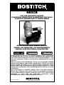
N80CB
COIL-FED PNEUMATIC NAILERS
CLAVADORAS NEUMÁTICAS ALIMENTADAS POR ROLLO
CLOUEURS PNEUMATIQUES À ENROULEMENT
OPERATION and MAINTENANCE MANUAL
MANUAL DE OPERACIÓN y DE MANTENIMIENTO
MANUEL D’INSTRUCTIONS et D’ENTRETIEN
ADVERTENCIA:
ATTENTION:
BEFORE OPERATING THIS TOOL, ALL OPERATORS SHOULD STUDY THIS MANUAL,
TO UNDERSTAND AND FOLLOW THE SAFETY WARNINGS AND INSTRUCTIONS.
KEEP THESE INSTRUCTIONS WITH THE TOOL FOR FUTURE REFERENCE. IF YOU
HAVE ANY QUESTIONS, CONTACT YOUR BOSTITCH REPRESENTATIVE OR DISTRIBUTOR.
ANTES DE OPERAR ESTA HERRAMIENTA, TODOS LOS OPERADORES DEBERÁN
ESTUDIAR ESTE MANUAL PARA PODER COMPRENDER Y SEGUIR LAS ADVERTENCIAS SOBRE SEGURIDAD Y LAS INSTRUCCIONES. MANTENGA ESTAS
INSTRUCCIONES CON LA HERRAMIENTA PARA FUTURA REFERENCIA. SI TIENE
ALGUNA DUDA, COMUNÍQUESE CON SU REPRESENTANTE DE BOSTITCH O CON SU
DISTRIBUIDOR.
LIRE ATTENTIVEMENT LE PRÉSENT MANUEL AVANT D’UTILISER L’APPAREIL.
PRÊTER UNE ATTENTION TOUTE PARTICULIÈRE AUX CONSIGNES DE SÉCURITÉ
ET AUX AVERTISSEMENTS. GARDER CE MANUEL AVEC L’OUTIL POUR FUTURE
RÉFÉRENCE. SI VOUS AVEZ DES QUESTIONS, CONTACTEZ VOTRE
REPRÉSENTANT OU VOTRE CONCESSIONNAIRE BOSTITCH.
102775 REV F 2/00
Stanley Fastening Systems
INTRODUCTION
The Bostitch N80CB is a precision-built tool; designed for high speed, high volume nailing. These tools will deliver efficient, dependable service when used correctly and with
care. As with any fine power tool, for best performance the manufacturer’s instructions
must be followed. Please study this manual before operating the tool and understand
the safety warnings and cautions. The instructions on installation, operation and maintenance should be read carefully, and the manual kept for reference. NOTE: Additional
safety measures may be required because of your particular application of the tool.
Contact your Bostitch representative or distributor with any questions concerning the
tool and its use. Bostitch, Inc., East Greenwich, Rhode Island 02818.
INDEX
Warranty . . . . . . . . . . . . . . . . . . . . . . . . . . . . . . . . . . . . . . . . . . . . . . . .2
Safety Instructions . . . . . . . . . . . . . . . . . . . . . . . . . . . . . . . . . . . . . . . .3
Tool Specifications: Air Consumption & Operating Pressure . . . . . . . . 4
Air Supply: Fittings, Hoses, Filters, Regulators . . . . . . . . . . . . . . . . . . .5
Lubrication and Cold Weather Operation . . . . . . . . . . . . . . . . . . . . . . . .5
Loading the Tool . . . . . . . . . . . . . . . . . . . . . . . . . . . . . . . . . . . . . . . . .6
Adjusting for Nail Length . . . . . . . . . . . . . . . . . . . . . . . . . . . . . . . . . . . .6
Operating the Tool . . . . . . . . . . . . . . . . . . . . . . . . . . . . . . . . . . . . .7 & 8
Basic Tool Function Diagram . . . . . . . . . . . . . . . . . . . . . . . . . . . . . . . . .9
Maintaining the Pneumatic Tool . . . . . . . . . . . . . . . . . . . . . . . . . . . . . . .9
Trouble Shooting . . . . . . . . . . . . . . . . . . . . . . . . . . . . . . . . . . . . . . . .10
Driver Maintenance/Adjusting Exhaust . . . . . . . . . . . . . . . . . . . . . . . . .11
Accessories . . . . . . . . . . . . . . . . . . . . . . . . . . . . . . . . . . . . . . . . . . . .11
NOTE:
Bostitch tools have been engineered to provide excellent customer satisfaction and are
designed to achieve maximum performance when used with precision Bostitch fasteners
engineered to the same exacting standards. Bostitch cannot assume responsibility for
product performance if our tools are used with fasteners or accessories not meeting
the specific requirements established for genuine Bostitch nails, staples and accessories.
LIMITED WARRANTY
Bostitch, Inc., warrants to the original retail purchaser that this product is free from defects
in material and workmanship, and agrees to repair or replace, at Bostitch's option, any
defective product within 1 year from the date of purchase This warranty is not transferable. It only covers damage resulting from defects in material or workmanship, and it does
not cover conditions or malfunctions resulting from normal wear, neglect, abuse, accident
or repairs attempted or made by other than our regional repair center or authorized warranty service center. Driver blades, bumpers and o-rings are considered normally wearing
parts.
THIS WARRANTY IS IN LIEU OF ALL OTHER EXPRESS WARRANTIES. ANY WARRANTY OF MERCHANTABILITY OR FITNESS FOR A PARTICULAR PURPOSE IS LIMITED TO THE DURATION OF THIS WARRANTY. BOSTITCH SHALL NOT BE LIABLE
FOR ANY INCIDENTAL OR CONSEQUENTIAL DAMAGES.
This warranty is limited to sales in the United States and Canada. Some states do not
allow limitations on how long an implied warranty lasts, or the exclusion or limitation of incidental or consequential damages, so the above limitations or exclusions may not apply to
you. This warranty gives you specific legal rights, and you may also have other rights
which vary from state to state.
To obtain warranty service, return the product at your expense together with proof of purchase to a Bostitch Regional or authorized warranty repair center. You may call us at 1800-556-6696 for the location of authorized warranty service centers in your area.
-2-
SAFETY INSTRUCTIONS
EYE PROTECTION which conforms to ANSI specifications and provides protection
against flying particles both from the FRONT and SIDE should ALWAYS be worn by
the operator and others in the work area when loading, operating or servicing this
tool. Eye protection is required to guard against flying fasteners and debris, which
could cause severe eye injury.
The employer and/or user must ensure that proper eye protection is worn. Eye protection equipment must conform to the requirements of the American National
Standards Institute, ANSI Z87.1-1989 and provide both frontal and side protection.
NOTE: Non-side shielded spectacles and face shields alone do not provide adequate protection.
CAUTION: ADDITIONAL SAFETY PROTECTION will be required in some environments. For example, the working area may include exposure to noise level which can
lead to hearing damage. The employer and user must ensure that any necessary
hearing protection is provided and used by the operator and others in the work area.
Some environments will require the use of head protection equipment. When
required, the employer and user must ensure that head protection conforming to
ANSI Z89.1 1986 is used.
AIR SUPPLY AND CONNECTIONS
Do not use oxygen, combustible gases, or bottled gases as a power source for this
tool as tool may explode, possibly causing injury.
Do not use supply sources which can potentially exceed 200 P.S.I.G. as tool may
burst, possibly causing injury.
The connector on the tool must not hold pressure when air supply is disconnected. If a wrong fitting is used, the tool can remain charged with air after disconnecting and thus will be able to drive a fastener even after the air line is disconnected possibly causing injury.
Do not pull trigger or depress contact arm while connected to the air supply as the
tool may cycle, possibly causing injury.
Always disconnect air supply: 1.) Before making adjustments; 2.) When servicing the
tool; 3.) When clearing a jam; 4.) When tool is not in use; 5.) When moving to a different work area, as accidental actuation may occur, possibly causing injury.
LOADING TOOL
When loading tool: 1.) Never place a hand or any part of body in fastener discharge
area of tool; 2.) Never point tool at anyone; 3.) Do not pull the trigger or depress
the trip as accidental actuation may occur, possibly causing injury.
OPERATION
Always handle the tool with care: 1.) Never engage in horseplay; 2.) Never pull
the trigger unless nose is directed toward the work; 3.) Keep others a safe distance from the tool while tool is in operation as accidental actuation may occur,
possibly causing injury.
The operator must not hold the trigger pulled on contact arm tools except during fastening operation as serious injury could result if the trip accidentally contacted someone or something, causing the tool to cycle.
Keep hands and body away from the discharge area of the tool. A contact arm tool
may bounce from the recoil of driving a fastener and an unwanted second fastener may be driven possibly causing injury.
Check operation of the contact arm mechanism frequently. Do not use the tool if
the arm is not working correctly as accidental driving of a fastener may result. Do
not interfere with the proper operation of the contact arm mechanism.
Do not drive fasteners on top of other fasteners or with the tool at an overly steep
angle as this may cause deflection of fasteners which could cause injury.
Do not drive fasteners close to the edge of the work piece as the wood may split,
allowing the fastener to be deflected possibly causing injury.
MAINTAINING THE TOOL
When working on air tools note the warnings in this manual and use extra care
when evaluating problem tools.
-3-
N80CB TOOL SPECIFICATIONS
All screws and nuts are metric.
MODEL
TOOL
ACTUATION
LENGTH
HEIGHT
N80CB-1
Contact Trip
12-1/16” (306mm)
13-1/4” (336mm)
5-9/16” (140mm)
WIDTH
8lb. 8oz. (3.86kgs.)
WEIGHT
N80CB-2
Sequential Trip
12-1/16” (306mm)
13-1/4” (336mm)
5-9/16” (140mm)
8lb. 8oz. (3.86kgs.)
TOOL AIR FITTING:
This tool uses a 1/4 N.P.T. male plug. The inside diameter should be .275” (7mm) or larger.
The fitting must be capable of discharging tool air pressure when disconnected from the air
supply. The connector socket on the air hose should be .275” (7mm) inside diameter or larger.
OPERATING PRESSURE:
70 to 100 p.s.i.g. (4.9 to 7.0 kg/cm2). Select the operating pressure within this range for best
fastener performance.
DO NOT EXCEED THIS RECOMMENDED OPERATING PRESSURE.
AIR CONSUMPTION:
The N80CB requires 7.2 cubic feet per minute of free air to operate at the rate of 100 nails per
minute, at 80 p.s.i.g. (5.6 kg/cm2). Take the actual rate at which the tool will be run to
determine the amount of air required. For instance, if your fastener usage averages 50 nails
per minute, you need 50% of the 7.8 c.f.m. which is required for running at 100 nails per minute.
OPERATION
BOSTITCH OFFERS TWO TYPES OF OPERATION FOR THIS SERIES TOOL
CONTACT TRIP
The common operating procedure on “Contact Trip” tools is for the operator to contact the work
to actuate the trip mechanism while keeping the trigger pulled, thus driving a fastener each
time the work is contacted. This will allow rapid fastener placement on many jobs, such as
sheathing, decking and pallet assembly.
All pneumatic tools are subject to recoil when driving fasteners. The tool may bounce,
releasing the trip, and if unintentionally allowed to recontact the work surface with the trigger
still actuated (finger still holding trigger pulled) an unwanted second fastener will be driven.
SEQUENTIAL TRIP
The Sequential Trip requires the operator to hold the tool against the work before pulling the
trigger. This makes accurate fastener placement easier, for instance on framing, toe nailing
and crating applications.
The Sequential Trip allows exact fastener location without the possibility of driving a second
fastener on recoil, as described under “Contact Trip”.
The Sequential Trip Tool has a positive safety advantage because it will not accidentally drive a
fastener if the tool is contacted against the work – or anything else – while the operator is
holding the trigger pulled.
MODEL IDENTIFICATION:
Refer to Operation Instructions on page 4 before proceeding to use this tool.
CONTACT TRIP
Identified by:
BLACK TRIGGER
SEQUENTIAL TRIP
Identified by:
GRAY TRIGGER
-4-
AIR SUPPLY AND CONNECTIONS
Do not use oxygen, combustible gases, or bottled gases as a power
source for this tool as tool may explode, possibly causing injury.
FITTINGS:
Install a male plug on the tool which is free flowing and which will release air pressure
from the tool when disconnected from the supply source.
HOSES:
Air hoses should have a minimum of 150 p.s.i. (10.6 kg/cm2) working pressure rating or
150 percent of the maximum pressure that could be produced in the air system. The
supply hose should contain a fitting that will provide “quick disconnecting” from the male
plug on the tool.
SUPPLY SOURCE:
Use only clean regulated compressed air as a power source for this tool. NEVER USE
OXYGEN, COMBUSTIBLE GASES, OR BOTTLED GASES, AS A POWER SOURCE FOR
THIS TOOL AS TOOL MAY EXPLODE.
REGULATOR:
A pressure regulator with an operating pressure of 0 - 125 p.s.i. (0 - 8.79 KG/CM2) is
required to control the operatiing pressure for safe operation of this tool. Do not connect this
tool to air pressure which can potentially exceed 200 p.s.i. (14 KG/CM2)as tool may fracture or
burst, possibly causing injury.
OPERATING PRESSURE:
Do not exceed recommended maximum operating pressure as tool wear will be greatly
increased. The air supply must be capable of maintaining the operating pressure at the tool.
Pressure drops in the air supply can reduce the tool’s driving power. Refer to “TOOL SPECIFICATIONS” for setting the correct operating pressure for the tool.
FILTER:
Dirt and water in the air supply are major causes of wear in pneumatic tools. A filter will
help to get the best performance and minimum wear from the tool. The filter must have adequate flow capacity for the specific installation. The filter has to be kept clean to be effective in
providing clean compressed air to the tool. Consult the manufacturer’s instructions on proper
maintenance of your filter. A dirty and clogged filter will cause a pressure drop which will
reduce the tool’s performance.
LUBRICATION
Frequent, but not excessive, lubrication is required for best performance. Oil added through the
air line connection will lubricate the internal parts. Use BOSTITCH Air Tool Lubricant, Mobil Velocite
#10, or equivalent. Do not use detergent oil or additives as these lubricants will cause accelerated wear
to the seals and bumpers in the tool, resulting in poor tool performance and frequent tool maintenance.
If no airline lubricator is used, add oil during use into the air fitting on the tool once or twice a day. Only
a few
drops of oil at a time is necessary. Too much oil will only collect inside the tool and will be
noticeable in the exhaust cycle.
COLD WEATHER OPERATION:
For cold weather operation, near and below freezing, the moisture in the air line may freeze and prevent
tool operation. We recommend the use of BOSTITCH WINTER FORMULA air tool lubricant or permanent antifreeze (ethylene glycol) as a cold weather lubricant.
CAUTION: Do not store tools in a cold weather environment to prevent frost or ice formation on
the tools operating valves and mechanisms that could cause tool failure.
NOTE: Some commercial air line drying liquids are harmful to “O”-rings and seals – do not use
these low temperature air dryers without checking compatibility.
-5-
LOADING THE N80CB SERIES COIL NAILER
EYE PROTECTION which conforms to ANSI specifications and provides protection against flying particles both from the FRONT and SIDE should ALWAYS be
worn by the operator and others in the work area when loading, operating or servicing this tool. Eye protection is required to guard against flying fasteners and
debris, which could cause severe eye injury.
The employer and/or user must ensure that proper eye protection is worn. Eye
protection equipment must conform to the requirements of the American National
Standards Institute, ANSI Z87.1-1989 and provide both frontal and side protection.
NOTE: Non-side shielded spectacles and face shields alone do not provide adequate protection.
TO PREVENT ACCIDENTAL INJURIES:
• Never place a hand or any other part of the body in nail discharge area of tool
while the air supply is connected.
• Never point the tool at anyone else.
• Never engage in horseplay.
• Never pull the trigger unless nose is directed toward the work.
• Always handle the tool with care.
• Do not pull the trigger or depress the trip mechanism while loading the tool.
Canister
cover
Door
Canister
bracket
Canister
latch
Feed pawl
Canister
bottom
1. Open the magazine: pull down down latch and swing door open. Swing magazine cover open.
2. Check adjustment: the nailer must be set for the length of nail to be used. Nails will not feed
smoothly if the magazine is not correctly adjusted.
The N80CB accepts from 1-1/2” to 3-1/4” nails. To change setting:
a) Release the canister latch on the rear of the canister.
b) Pull out canister bottom by swinging right to left until tabs disengage.
c) Inside the canister bracket are settings in inches and millimeters. The canister is adjusted correctly
when the length of the nail being used is shown in the window of the canister bottom.
IN.
1 3/4
MM
(45)
2
(50)
2 1/4
(57)
2 1/2
(65)
2 3/4
(70)
3
(75)
3 1/4
(83)
Canister
bracket
3. Load the coil of nails:
Place a coil of nails over the post in the canister.
Uncoil enough nails to reach the feed pawl, and
place the second nail between the teeth on the
feed pawl. The nail heads fit in slot on nose.
4. Swing cover closed.
Canister
bottom
5. Close the door.
Check that latch engages. (If it does not engage,
check that the nail heads are in the slot on the
nose).
Window
Note: The canister is adjusted correctly for 1-1/2”
and 1-3/4” nails when “1-3/4 (45)” appears in the
window of the canister bottom.
NOTE: Use only nails recommended by Bostitch for use in Bostitch N80CB Series nailers or nails
which meet Bostitch specifications.
-6-
TOOL OPERATION
EYE PROTECTION which conforms to ANSI specifications and provides protection against flying particles both from the FRONT and SIDE should
ALWAYS be worn by the operator and others in the work area when loading,
operating or servicing this tool. Eye protection is required to guard against
flying fasteners and debris, which could cause severe eye injury.
The employer and/or user must ensure that proper eye protection is worn.
Eye protection equipment must conform to the requirements of the American
National Standards Institute, ANSI Z87.1-1989 and provide both frontal and
side protection. NOTE: Non-side shielded spectacles and face shields alone
do not provide adequate protection.
BEFORE HANDLING OR OPERATING THIS TOOL:
I. READ AND UNDERSTAND THE WARNINGS CONTAINED IN
THIS MANUAL.
II. REFER TO “TOOL SPECIFICATIONS” IN THIS MANUAL TO
IDENTIFY THE OPERATING SYSTEM ON YOUR TOOL.
There are three available systems on BOSTITCH pneumatic tools. They are:
1. TRIGGER OPERATION 2. CONTACT TRIP OPERATION 3. SEQUENTIAL TRIP OPERATION
OPERATION
1. TRIGGER OPERATION
A TRIGGER OPERATED tool requires a single action to drive a fastener. Each time the
trigger is pulled the tool will drive a fastener. The trigger operated model is intended for
use only when a contact trip or sequential trip cannot be used due to the requirements of
the application.
2. CONTACT TRIP OPERATION
The CONTACT TRIP MODEL tool contains a contact trip that operates in conjunction with
the trigger to drive a fastener. There are two methods of operation to drive fasteners with
a contact trip tool.
A. SINGLE FASTENER PLACEMENT: To operate the tool in this manner, first
position the contact trip on the work surface, WITHOUT PULLING THE TRIGGER.
Depress the contact trip until the nose touches the work surface and then pull the
trigger to drive a fastener. Do not press the tool against the work with extra force.
Instead, allow the tool to recoil off the work surface to avoid a second unwanted
fastener. Remove your finger from the trigger after each operation.
B. RAPID FASTENER OPERATION: To operate the tool in this manner, hold the
tool with the contact trip pointing towards but not touching the work surface. Pull
the trigger and then tap the contact trip against the work surface using a bouncing
motion. Each depression of the contact trip will cause a fastener to be driven.
The operator must not hold the trigger pulled on contact trip tools
except during fastening operation, as serious injury could result if the
trip accidentally contacted someone or something, causing the tool to
cycle.
Keep hands and body away from the discharge area of the tool. A contact trip tool may bounce from the recoil of driving a fastener and an
unwanted second fastener may be driven, possibly causing injury.
3. SEQUENTIAL TRIP OPERATION:
The SEQUENTIAL TRIP MODEL contains a contact trip that operates in conjunction with
the trigger to drive a fastener. To operate a sequential trip tool, first position the contact
trip on the work surface WITHOUT PULLING THE TRIGGER. Depress the contact trip
and then pull the trigger to drive a fastener. As long as the contact trip is contacting the
work and is held depressed, the tool will drive a fastener each time the trigger is
depressed. If the contact trip is allowed to leave the work surface, the sequence
described above must be repeated to drive another fastener.
-7-
TOOL OPERATION CHECK:
CAUTION: Remove all fasteners from tool before performing tool operation check.
1. TRIGGER OPERATED TOOL:
A. With finger off the trigger, hold the tool with a firm grip on the handle.
B. Place the nose of the tool against the work surface.
C. Pull the trigger to drive. Release the trigger and cycle is complete.
CAUTION: THE TOOL WILL CYCLE EACH TIME THE TRIGGER IS PULLED!
2. CONTACT TRIP OPERATION:
A. With finger off the trigger, press the contact trip against the work surface.
THE TOOL MUST NOT CYCLE.
B. Hold the tool off the work surface, and pull the trigger.
THE TOOL MUST NOT CYCLE.
C. With the tool off the work surface, pull the trigger.
Press the contact trip against the work surface.
THE TOOL MUST CYCLE.
D. Without touching the trigger, press the contact trip against the work surface,
then pull the trigger.
THE TOOL MUST CYCLE.
3. SEQUENTIAL TRIP OPERATION:
A. Press the contact trip against the work surface, without touching the trigger.
THE TOOL MUST NOT CYCLE.
B. Hold the tool off the work surface and pull the trigger.
THE TOOL MUST NOT CYCLE.
Release the trigger. The trigger must return to the trigger stop on the frame.
C. Pull the trigger and press the contact trip against the work surface.
THE TOOL MUST NOT CYCLE.
D. With finger off the trigger, press the contact trip against the work surface. Pull the trigger.
THE TOOL MUST CYCLE.
IN ADDITION TO THE OTHER WARNINGS CONTAINED IN THIS MANUAL OBSERVE THE FOLLOWING FOR SAFE OPERATION
• Use the BOSTITCH pneumatic tool only for the purpose for which it was
designed.
• Never use this tool in a manner that could cause a fastener to be directed toward the user
or others in the work area.
• Do not use the tool as a hammer.
• Always carry the tool by the handle. Never carry the tool by the air hose.
• Do not alter or modify this tool from the original design or function without approval from
BOSTITCH, INC.
• Always be aware that misuse and improper handling of this tool can cause injury to
yourself and others.
• Never clamp or tape the trigger or contact trip in an actuated position.
• Never leave a tool unattended with the air hose attached.
• Do not operate this tool if it does not contain a legible WARNING LABEL.
• Do not continue to use a tool that leaks air or does not function properly. Notify your
nearest Bostitch representative if your tool continues to experience
functional problems.
-8-
BASIC TOOL OPERATION
Bostitch pneumatic tools are cycled by a compressed air operated single piston design.
The following illustrations show the four functional cycles that occur when the tool is operated to
drive a fastener:
EXHAUST
OPEN
FIG.1
AT REST
FIG.2
DRIVING STROKE
PISTON
STOP
RESERVOIR
OF HIGH
PRESSURE
AIR
EXHAUST
SEALED BY
PISTON STOP
HEAD VALVE CLOSED
TRIGGER VALVE PORT
HEAD VALVE
TRIGGER VALVE PORT
BLOCKED
(TO SUPPLY AIR TO TOP OF HEAD VALVE)
RESERVOIR OF
HIGH PRESSURE AIR
HOLES IN
CYLINDER
WALL
RETURN
CHAMBER
TRIGGER VALVE
ACTUATED
TRIGGER VALVE RELEASED
BUMPER
PASSAGE FOR
AIR RELEASED FROM HEAD VALVE
AIR RELEASED
FROM ABOVE
HEAD VALVE
SLOTS FOR AIR FLOW
FOR PISTON RETURN
EXHAUST
STILL
CLOSED
FIG.3
END OF STROKE
TRIGGER STILL
PULLED
EXHAUST
OPEN
HEAD VALVE CLOSED
HEAD VALVE OPEN
AIR FLOWS
INTO
RETURN
CHAMBER
PISTON IS
SEALED
AGAINST
BUMPER
FIG.4
RETURNING
AIR IN
RETURN
CHAMBER
PUSHES
PISTON
UPWARD
TRIGGER VALVE
STILL ACTUATED
TRIGGER VALVE
RELEASED –
AIR PRESSURE RETURNS
TO TOP OF HEAD VALVE
MAINTAINING THE PNEUMATIC TOOL
When working on air tools, note the warnings in this manual and use extra care
evaluating problem tools.
CAUTION: Pusher spring (constant force spring). Caution must be used when working with
the spring assembly. The spring is wrapped around, but not attached to, a roller. If the spring
is extended beyond its length, the end will come off the roller and the spring will roll up with a
snap, with a chance of pinching your hand. Also the edges of the spring are very thin and
could cut. Care must also be taken to insure no permanent kinks are put in the spring as this
will reduce the springs force.
REPLACEMENT PARTS:
BOSTITCH replacement parts are recommended. Do not use modified parts or parts
which will not give equivalent performance to the original equipment.
ASSEMBLY PROCEDURE FOR SEALS:
When repairing a tool, make sure the internal parts are clean and lubricated. Use Parker “O”-LUBE
or equivalent on all “O”-rings. Coat each “O”-ring with “O”-LUBE before assembling. Use a small
amount of oil on all moving surfaces and pivots. After reassembly add a few drops of
BOSTITCH Air Tool Lubricant through the air line fitting before testing.
AIR SUPPLY-PRESSURE AND VOLUME:
Air volume is as important as air pressure. The air volume supplied to the tool may be inadequate
because of undersize fittings and hoses, or from the effects of dirt and water in the system.
Restricted air flow will prevent the tool from receiving an adequate volume of air, even though the
pressure reading is high. The results will be slow operation, misfeeds or reduced driving power.
Before evaluating tool problems for these symptoms, trace the air supply from the tool to the supply
source for restrictive connectors, swivel fittings, low points containing water and anything else that
would prevent full volume flow of air to the tool.
-9-
TROUBLE SHOOTING
PROBLEM
CAUSE
Trigger valve housing leaks air
Trigger valve stem leaks air
Frame/nose leaks air
O-ring cut or cracked . . . . . . . . . . . . . .Replace O-ring
O-ring/seals cut or cracked . . . . . . . . . .Replace trigger valve assembly
Loose nose screws . . . . . . . . . . . . . . . .Tighten and recheck
O-ring or Gasket is cut or cracked . . . . .Replace O-ring or gasket
Bumper cracked/worn . . . . . . . . . . . . . .Replace bumper
Damaged gasket or seal . . . . . . . . . . . .Replace gasket or seal
Cracked/worn head valve bumper . . . . .Replace bumper
Loose cap screws . . . . . . . . . . . . . . . . .Tighten and recheck
Air supply restriction . . . . . . . . . . . . . . .Check air supply equipment
Tool dry, lack of lubrication . . . . . . . . . .Use BOSTITCH Air Tool Lubricant
Worn head valve O-rings . . . . . . . . . . .Replace O-rings
Broken cylinder cap spring . . . . . . . . . .Replace cylinder cap spring
Head valve stuck in cap . . . . . . . . . . . .Disassemble/Check/Lubricate
Tool dry, lacks lubrication . . . . . . . . . . .Use BOSTITCH Air Tool Lubricant
Broken cylinder cap spring . . . . . . . . . .Replace cap spring
O-rings/seals cut or cracked . . . . . . . . .Replace O-rings/seals
Exhaust blocked . . . . . . . . . . . . . . . . .Check bumper, head valve spring, muffler
Trigger assembly worn/leaks . . . . . . . . .Replace trigger assembly
Dirt/tar build up on driver . . . . . . . . . . .Disassemble nose/driver to clean
Cylinder sleeve not seated correctly
on bottom bumper . . . . . . . . . . . . . . . .Disassemble to correct
Head valve dry . . . . . . . . . . . . . . . . . . .Disassemble/lubricate
Air pressure too low . . . . . . . . . . . . . . .Check air supply equipment
Worn bumper . . . . . . . . . . . . . . . . . . . .Replace bumper
Tar/dirt in driver channel . . . . . . . . . . . .Disassemble and clean nose and driver
Air restriction/inadequate air flow through
quick disconnect socket and plug . . . . .Replace quick disconnect fittings
Worn piston O-ring . . . . . . . . . . . . . . . .Replace O-ring, check driver
Tool dry, lacks lubrication . . . . . . . . . . .Use BOSTITCH Air Tool Lubricant
Damaged pusher spring . . . . . . . . . . . .Replace spring
Low air pressure . . . . . . . . . . . . . . . . . .Check air supply system to tool
Loose magazine nose screws . . . . . . . .Tighten all screws
Fasteners too short for tool . . . . . . . . . .Use only recommended fasteners
Bent fasteners . . . . . . . . . . . . . . . . . . .Discontinue using these fasteners
Wrong size fasteners . . . . . . . . . . . . . .Use only recommended fasteners
Leaking head cap gasket . . . . . . . . . . .Tighten screws/replace gasket
Trigger valve O-ring cut/worn . . . . . . . .Replace O-ring
Broken/chipped driver . . . . . . . . . . . . . .Replace driver (check piston O-ring)
Dry/dirty magazine . . . . . . . . . . . . . . . .Clean/lubricate use BOSTITCH
.Air Tool Lubricant
Worn magazine . . . . . . . . . . . . . . . . . .Replace magazine
Driver channel worn . . . . . . . . . . . . . . .Replace nose/check door
Wrong size fasteners . . . . . . . . . . . . . .Use only recommended fasteners
Bent fasteners . . . . . . . . . . . . . . . . . . .Discontinue using these fasteners
Loose magazine/nose screws . . . . . . . .Tighten all screws
Broken/chipped driver . . . . . . . . . . . . . .Replace driver
Frame/cap leaks air
Failure to cycle
Lack of power; slow to cycle
Skipping fasteners; intermittent feed
Fasteners jam in tool
CORRECTION
COIL NAILERS
Skipping fasteners; intermittent feed
Fasteners jam in tool/canister
Feed piston dry . . . . . . . . . . . . . . . . . .Add BOSTITCH Air Tool Lubricant
in hole in feed piston cover
Feed piston O-rings cracked/worn . . . .Replace O-rings/check bumper and spring.
Lubricate assembly.
Check Pawl binding . . . . . . . . . . . . . . .Inspect Pawl and spring on door.
Must work freely.
Canister bottom not set correctly . . . . .Set canister bottom for length of nails
being used
Broken weld wires in nail coil . . . . . . . .Remove coil of nails and use another coil
Wrong size fasteners for tool . . . . . . . .Use only recommended fasteners/check
canisterbottom adjustment
Broken welded wires in nail coil . . . . . .Remove coil of nails and use another coil
Wrong slide plate adjustment for
wire/plastic collated nail coil . . . . . . . . .Adjust switch pins for wire/plastic collated
nail coil
-10-
N80CB DRIVER MAINTENANCE INSTRUCTIONS
Worn driver causing poor quality or loss of power:
• Wear on the driving tip will affect the nail drive, giving symptoms of bent and incompletely driven
nails, and damaged nail heads.
• The driver length may be adjusted to allow the driving tip to be redressed to compensate for
wear. Heat and precise measurement are required. Contact a qualified service technician for
this adjustment.
• The length setting for a new driver is shown below. Measurement is from the bottom face of the
main piston.
• Note that the measurement from the top of the piston gives the maximum amount the driver
may be adjusted to allow redressing. Always extend the driver the minimum required to allow
redressing to restore the driving end; several redressings will be possible before this maximum
depth is reached.
6.000"- –6.020”
6.020"
6.000”
Standard
Length N80CB/N80P
N80CB/N80P
Standard
Length
(152.4mm – 152.9mm)
(152.4mm - 152.9mm)
SEE NOTE
3/8" (9.5mm) maximum limit of driver recessed
into piston. Do not exceed this limit
NOTE: WHEN DRESSING IS REQUIRED, USE
.015" - .025 x 45˚ CHAMFER
(.38 - .64mm x 45˚ CHAMFER)
NOTE: Driver wear of approximately 1/8” (3mm) can be tolerated in most applications.
However, in difficult driving applications, driver wear or approximately 1/16” (1.5mm) may
cause a slight reduction in the apparent driving power.
NOTE: For “Flush-Driving”, length settings shorter than shown above may be used.
However, the adjusted length should never be less than 5.705” (144.9mm), or more than
6.055” (153.8mm), otherwise normal nailer function may be adversely affected.
DIRECTIONAL EXHAUST DEFLECTOR
Loosen screw as shown. Adjust to desired exhaust direction and tighten screw.
ACCESSORIES AVAILABLE:
BC601
BC602
BC603
BC604
100679
SEQ1
N80K2
N80CK1
N80CK2
ORK11
BK3
N80154A
pallets
851325
831385
105005
4 oz. Bostitch Air-Tool Lubricant
1 pint Bostitch Air-Tool Lubricant
1 pint Bostitch “Winter-Formula” Air-Tool Lubricant
1 quart Bostitch Air-Tool Lubricant
Lube 1 lb. can
Sequential Trip Conversion Kit
Remote Control Kit
Smooth Trip Kit
Dial-A-DepthTM Fastener Control Kit
O-Ring Kit
Bumper Kit
Replacement Driver Assembly - A “Hard Driver” for high volume applications, such as
Loctite 271 (.02 oz.)
Loctite 242 (.02 oz.)
Assembly, Adjustable Contact Trip
-11-