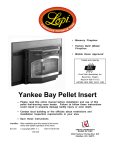
1
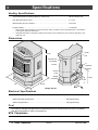
Astoria™ Pellet Stove • Horizontal Or Vertical Vent • Freestanding Stove • Mobile Home Approved • Class A Chimney Retrofit • Hearth Stove into Existing Masonry Chimney , Masonry Fireplace, or Z.C. Fireplace Tested and Listed by Omni-Test Laboratories, Inc. Portland, Oregon Report # 028-S-42-2 ASTM E1509-2004 - - Please read this entire manual before installation and use of this pellet fuelburning room heater. Failure to follow these instructions could result in property damage, bodily injury, or even death. - - Contact local building or fire officials about restrictions and installation inspection requirements in your area. - - Save these instructions. Installer: After installation give this manual to the home-owner and explain operation of this stove. $10.00 Copyright 2008, T.I. 4080725 Part # 100-01154 4800 Harbour Pointe Blvd. SW Mukilteo, WA 98275 Introduction 2 Introduction We welcome you as a new owner of an Astoria pellet heater. In purchasing an Astoria you have joined the growing ranks of concerned individuals whose selection of an energy system reflects both a concern for the environment and aesthetics. The Astoria is one of the finest home heaters the world over. This manual will explain the installation, operation, and maintenance of this pellet-burning heater. Please familiarize yourself with the Owner's Manual before operating your heater and save the manual for future reference. Included are helpful hints and suggestions which will make the installation and operation of your new heater an easier and more enjoyable experience. We offer our continual support and guidance to help you achieve the maximum benefit and enjoyment from your heater. Important Information No other Astoria heater has the same serial number as yours. The serial number is on the safety label on the back of the appliance. This serial number will be needed in case you require service of any type. Model: Astoria PS Serial Number: Purchase Date: To receive full warranty coverage, you will need to show evidence of the date you purchased your heater. Do not mail your Bill of Sale to us. We suggest that you attach your Bill of Sale to this page so that you will have all the information you need in one place should the need for service or information occur. Purchased From: © Travis Industries Mail your Warranty Card Today, and Save Your Bill of Sale. 4080725 100-0115 4 Table of Contents Introduction Operation (continued) Introduction ......................................................2 Important Information .........................................2 Safety Precautions Safety Precautions ............................................4 Specifications Heating Specifications ........................................6 Dimensions.......................................................6 Electrical Specifications......................................6 Fuel.................................................................6 EPA Compliance ................................................6 Installation Manual Mode.....................................................22 Auto Mode ........................................................23 Restrictor Adjustment .........................................24 Restrictor Adjustment .........................................24 Adjusting the Fan Speed......................................24 Start-Up Sequence.............................................25 "AUGER ON" Light..............................................25 "MAINTENANCE REQUIRED" Light ........................25 "MANUAL AUGER" Button....................................26 Power Outages..................................................26 Using a Pellet/Corn Mix with This Heater .................26 Maintenance Before You Begin ...............................................7 Packing List......................................................7 Installation Options ............................................7 Planning The Installation .....................................7 Stove Placement ...............................................7 Floor Protection Requirements..............................7 Clearances - Straight Installation ..........................8 Clearances - Corner Installation ............................8 Venting the Pellet Stove ......................................9 Maximum Venting Distance .............................9 Pellet Vent Type............................................10 Installing the Pellet Vent .................................10 Pellet Vent Termination...................................10 Mobile Home Requirements ..................................11 Outside Air (used for combustion) .........................11 Alcove Installation Requirements ..........................12 Baffle Installation...............................................12 Door Seal Verification .........................................12 Restrictor Adjustment .........................................12 Thermostat Installation .......................................13 Installation Example: Direct "Through-the-wall" Installation .......................................................14 Installation Example: Interior Vertical Installation ....15 Installation Example: Class A Chimney Retrofit ........16 InstallationExample: Masonry FireplaceHearthStove.......................17 InstallationExample: Zero-Clearance(Metal)FireplaceHearthStove..18 InstallationExample: FreestandingMasonry Chimney................19 Daily Maintenance (whenever using the stove).........27 Inspect the Burn ...........................................27 Make Sure Pellets are Not Piling Up...................27 Check Firepot for Clinkers ...............................28 Cleaning the Firepot .......................................28 Door Opening ...............................................29 Weekly Maintenance (or every 5 bags of pellets) ......30 Flyash Removal ............................................30 Clean the Hopper...........................................30 Clean the Heat Exchange Tubes.......................30 Clean the Baffles...........................................31 Sweep Ash Into Ashpan..................................32 Check Ashpan, Dispose if necessary ................33 Clean the Glass ............................................33 Yearly Maintenance (or every ton) .........................34 Clean the Vertical Exhaust Duct .......................34 Clean the Exhaust Blower ...............................35 Clean the Vent ..............................................35 Door Seal.....................................................36 Normal Operating Sounds Normal Operating Sounds ....................................39 Safety Label Safety Label .....................................................40 Warranty Warranty ..........................................................41 Index Operation Safety Notice ....................................................20 Location of Controls ...........................................20 Starting the Heater for the First Time ......................20 Loading Pellets..................................................21 The Two Modes of Operation ................................21 © Travis Industries 3 4080725 Index...............................................................42 100-01154 Safety Precautions 4 • Do not operate the heater if you smell smoke coming from the heater. Turn the M ODE switch to "OFF", monitor your heater, and call your dealer. Gas • Contact your local building officials to obtain a permit and information on any installation restrictions or inspection requirements in your area. Notify your insurance company of this heater as well. Ok • Never use gasoline, gasoline-type lantern fuel, kerosene, charcoal lighter fluid, or similar liquids to start or 'freshen up' a fire in this heater. Keep all such liquids well away from the heater while it is in use. a Se lan t • The exhaust system must be completely airtight and properly installed. The pellet vent joints must be sealed with RTV 500o F. (260o C.) silicone sealant. • Do not unplug the heater if you suspect a malfunction. Turn the MODE SWITCH to "OFF" and periodically inspect the heater. • This unit must be properly installed to prevent the possibility of a house fire. The instructions must be strictly adhered to. Do not use makeshift methods or compromise in the installation. • Never try to repair or replace any part of the heater unless instructions are given in this manual. All other work should be done by a trained technician. • Your heater requires periodic maintenance and cleaning (see "Maintaining Your Heater"). Failure to maintain your heater may lead to smoke spillage in your home. • The viewing door and ashpan must be closed and latched during operation. • Never block free airflow through the open vents of the unit. • Do not operate the heater if the flame becomes dark & sooty of if the firepot overfills with pellets. Turn the MODE SWITCH to "OFF" and periodically inspect the heater (see "Running Your Heater"). © Travis Industries A A A A AA A AA A AA AA A A AA AA AAA AAA AA AA AA AA 4080725 • Allow the heater to cool before carrying out any maintenance or cleaning. Ashes must be disposed in a metal container with a tight lid and placed on a non-combustible surface well away from the home or structure. • This heater is designed and approved for pelletized wood fuel or a mixture up to 50% corn, 50% pellets. See page 25 for details on using a corn pellet mix. 100-0115 4 Safety Precautions ? • The heater will not operate during a power outage. If a power outage does occur, check the heater for smoke spillage and open a window if any smoke spills into the room. • This heater must be connected to a standard 115 V., 60 Hz grounded electrical outlet. Do not use an adapter plug or sever the grounding plug. Do not route the electrical cord underneath, in front of, or over the heater. • Keep foreign objects out of the hopper. • When installed in a mobile home, the heater must be bolted to the floor, have outside air, and NOT BE INSTALLED IN THE BEDROOM (Per H.U.D. requirements). Check with local building officials. Mobile Home • Disconnect the power cord before performing any maintenance. NOTE: Turning the Mode Switch to "OFF" does not disconnect all power to the heater. This Manual 5 • The exhaust system should be checked twice a year minimum for any build-up of soot or creosote. • Do not throw this manual away. This manual has important operating and maintenance instructions that you will need at a later time. Always follow the instructions in this manual. • Do not touch the hot surfaces of the heater. Educate all children of the danger of a hightemperature heater. Young children should be supervised when they are in the same room as the heater. • Do not place clothing or other flammable items on or near the heater. Because this heater can be controlled by a thermostat there is a possibility of the heater turning on and igniting any items placed on or near it. • Travis Industries, Inc. grants no warranty, implied or stated, for the installation or maintenance of your heater, and assumes no responsibility of any consequential damage(s). Proposition 65 Warning: Fuels used in gas, woodburning or oil fired appliances, and the products of combustion of such fuels, contain chemicals known to the State of California to cause cancer, birth defects and other reproductive harm. California Health & Safety Code Sec. 25249.6 © Travis Industries 4080725 100-0115 4 Specifications 6 Heating Specifications Approximate Maximum Heating Capacity (in square feet)* ........................................800 to 2,250 Sq. Feet Burn Rate (Pounds per Hour)**............................................................................1.7 to 5.5 Maximum Burn Time on Low Burn** ......................................................................67.5 Hours Hopper Capacity ..............................................................................................115 Pounds * Heating capacity will vary depending on the home's floor plan, degree of insulation, and the outside temperature. It is also affected by the fuel size, quality, and moisture level. ** Small pellets will increase or decrease the stated burn rates and burn times. Differences of plus or minus 20% depending on fuel quality may occur. Dimensions Center 33-3/8" Line This tab is for 7-1/4" the scraper 4" rod tool. Diameter Air Inlet (1-3/4" Outside Exhaust 1/2" AA AA Diameter) 28" 17-5/8" 10-1/2” 26-1/2" Weight: 250 Lbs. Electrical Specifications Electrical Rating.........................................................................................115 Volts, 3.6 Amps, 60 Hz Watts During Start-Up Sequence ...................................................................400 (approximately) Watts During Operation ...............................................................................180 (approximately) Fuel • This heater is designed and approved for pelletized wood fuel or a mixture up to 50% corn, 50% pellets. See page 25 for details on using a corn pellet mix. EPA Compliance This heater has been tested exempt from EPA Phase II Requirements by OMNI-Test Laboratories, Inc. © Travis Industries 4080725 100-0115 4 Installation 7 (For Qualified Installers Only) Before You Begin READ THIS ENTIRE MANUAL BEFORE YOU INSTALL AND USE THIS HEATER. FAILURE TO FOLLOW THE INSTRUCTIONS MAY RESULT IN PROPERTY DAMAGE, BODILY INJURY, OR EVEN DEATH. Check with local building officials for any permits required for installation of this pellet heater and notify your insurance company before proceeding with installation. Packing List • Thermostat & Wire • Scraper Rod Tool • Brush • Spare Fuses Installation Options • • • • • Residential or Mobile Home (see the section "Mobile Home Requirements") Alcove Compatible (see the section "Alcove Installation") Horizontal or Vertical Vent Outside Air Compatible Vent with L-Vent, L-Vent Fireplace Liner, or Type A Chimney (with adapter) Planning The Installation HINT: HINT: HINT: HINT: Have an authorized Travis Industries dealer install this heater. If you install the heater yourself, have your dealer review your installation plans. Sketch out a detailed plan of the installation including dimensions. Then verify the dimensions with the requirements listed in this manual. When determining the location of the stove, locate the wall studs (for horizontal penetrations) and ceiling trusses (for vertical penetrations). You may wish to adjust the stove position slightly to ensure the vent does not intersect with a framing member. Place the heater outside and load 10 pounds of pellets inside the hopper. Plug the heater in and let it run on HIGH until the pellets run out. This will cure the paint and burn off any oil on the steel, eliminating any smell inside the home. Stove Placement • • HINT: • Stove must be placed so that no combustibles are within, or can swing within (e.g. drapes, doors), 36" of the front of the heater. If the stove is placed in a location where the ceiling height is less than 7', it must follow the requirements in the section "Alcove Installation Requirements". REDUCING CLEARANCES - Clearances may be reduced by methods specified in NFPA 211, listed wall shields, pipe shields, or other means approved by local building or fire officials. Heater and floor protection must be installed on a level, secure floor. Floor Protection Requirements • • The heater must be installed on a non-combustible floor protector extending the full width and depth of the heater and extending 6" in front (minimum 27-3/4" wide by 31" deep) (minimum .018" thick - 26 gauge) . Must extend under and 2" to each side and rear of a "Tee" (if used). © Travis Industries 4080725 100-0115 4 Installation 8 (For Qualified Installers Only) Clearances - Straight Installation Through the Wall Installations Interior Vertical Vents A A A A A A AAAAAAAA AAAAAAAA AAAAAAAA AAAAAAAA AAAAAAAA AAAAAA AAAAAAAA AAAAAA AAAAAAAA AAAAAA AAAAAAAA AAAAAAAA AAAAAAAA Clearances - Corner Installation Vent Clearance* “Tee” 3” Minimum 2” Minimum** 9” Minimum 9” Minimum 6” Minimum AAAAAAAA AAAAAAAA AAAAAAAA AAAAAAAA AAAAAAAA AAAAAAAA AAAAAAAA AAAAAAAA AAAAAA AAAAAAAA AAAAAA AAAAAAAA AAAAAA AAAAAAAA AAAAAAAA AAAAAAAA Floor Protection 6” Minimum Through the Interior Vertical Vents Wall Vents A AAAAAAAAAAAAAAA A AA AAAAAAAAAAAAA A AAAAAAAAAAAAAAA AAAAAAAAAAAA AAAAAAAAAAAA AAAAAAAAAAAAA AAAAAAAAAAAAAAAAAAAAAAAAA AAAAAAAAAAAA AAAAAAAAAAAAA AAAAA AAAAAAAAAAAA AAAAAAAAAAAAA AAAAA AAAAA AAAAAAAAAAAA AAAAAAAAAAAAA AAAAA AAAAA AAAAAAAAAAAA AAAAAAAAAAAAA AAAAA AAAAA AAAAAAAAAAAA AAAAAAAAAAAAA AAAAA AAAAA AAAAAAAAAAAA AAAAAAAAAAAAA AAAAA AAAAAAAAAAAA AAAAAAAAAAAAA AAAAAAAAAAAA AAAAAAAAAAAAA AAAAAAAAAAAA 3” Minimum Vent Clearance* 3” Minimum 45° 2” Minimum** 45° Elbow “Tee” 3” Minimum 3” Minimum 6” Minimum 6” Minimum Floor Protection * Install vent at clearance specified by the vent manufacturer. NOTE: If interior vertical vent is used, the stove to backwall dimension is determined by the vent being used. This dimension will vary depending on the brand of pellet vent used. To determine the distance from the backwall to the stove, connect the "Tee" and add the vent clearance . ** The floor protection must extend 2” or to the wall (whichever is less) – all vent clearances must be met. © Travis Industries 4080725 100-0115 4 Installation 9 (For Qualified Installers Only) Venting the Pellet Stove • INSTALL VENT AT CLEARANCES SPECIFIED BY THE VENT MANUFACTURER. • DO NOT CONNECT THE PELLET VENT TO A VENT SERVING ANY OTHER APPLIANCE OR STOVE. • DO NOT INSTALL A FLUE DAMPER IN THE EXHAUST VENTING SYSTEM OF THIS UNIT. • USE AN APPROVED WALL THIMBLE WHEN PASSING THE VENT THROUGH WALLS AND A CEILING SUPPORT/FIRE STOP SPACER WHEN PASSING THE VENT THROUGH CEILINGS (MAKE SURE TO MAINTAIN CLEARANCE TO ANY COMBUSTIBLES). • No more than one tee and 180° of elbows (one tee with two 90° elbows, one tee with one 90° and two 45° elbows, etc.). 33 Feet (max.) Maximum Venting Distance • Vent must have a support bracket every 5' of pellet vent when exterior of structure 30 Feet The vent height and run must not exceed the distance shown in the shaded region shown to the right. 25 Feet 20 Feet Venting into this shaded area may require restrictor adjustments. See the section “Restrictor Adjustment” for details. 15 Feet 10 Feet NOTE: To achieve optimum performance, we recommend keeping the vent as short as possible (horizontal run especially). 5 Feet © Travis Industries 4080725 10 Feet (max.) 5 Feet 0 Feet 0 Feet 100-0115 4 Installation 10 (For Qualified Installers Only) Pellet Vent Type • Must be 4" diameter Type "L" (except for masonry fireplace installations) - or - connect the vent to a factory built type "A" chimney. All vent joints (including adapters, elbows, etc…) must be sealed with 500° F. RTV silicone. Installing the Pellet Vent Seal each vent section (including adapters, elbows, etc...) by injecting a liberal amount of 500° F. RTV silicone into the gap between sections. V RT F. 0 ° ne 0 5 ico Sil • Horizontal sections must have a 1/4" rise every 12" of travel. • Pellet vent connections must be sealed airtight with 500° F. RTV silicone and screwed together with at least three sheet metal screws. Pellet Vent Termination • Vent must terminate on the exterior of the dwelling. Horizontal terminations must protrude a minimum12" from the wall. Vertical terminations must protrude a minimum 24" from the roof surface. In addition, all clearances listed below must be met. • Must have an approved cap (to prevent water from entering) or a 45° downturn with rodent screen. • If the termination is located on a windy side of the house, an approved house shield is recommended to prevent soot from building up on the side of the house. • Must not be located where it will become plugged by snow or other material. H G X A F B D C F H A E NOTE: Measure clearances to the nearest edge of the exhaust hood. A B C D E F G H X Minimum 4' clearance below or beside any door or window that opens (This clearance may be reduced to18” if using outside air (see page 11) – we recommend the door or window be kept closed during operation. Minimum 1’ clearance below or beside any window that does not open. Minimum 1' clearance above any door or window that opens Minimum 2' clearance from any adjacent building Minimum 7' clearance above any grade when adjacent to public walkways NOTE: Vent may not terminate in covered walkway or breezeway. Minimum 2' clearance above any grass, plants, or other combustible materials Minimum 3' clearance from any forced air intake of any other appliance Minimum 2' clearance below eaves or overhangs Minimum 1' clearance horizontally from combustible wall Must be a minimum of 2' above the roof © Travis Industries 4080725 100-0115 4 Installation 11 (For Qualified Installers Only) Mobile Home Requirements • Outside air is required (used for combustion) - see the directions below. • The heater must be bolted to the floor (Some states do not require this; check with your local building department). See the illustration to the right. • The heater must be grounded to the steel chassis of the mobile home (Some states do not require this; check with your local building department). WARNING: CAUTION: b Use the lag bolts (used to secure the stove to the pallet) to screw the pedestal to the floor. 7/16” Socket a DO NOT INSTALL IN SLEEPING ROOM. THE STRUCTURAL INTEGRITY OF THE MANUFACTURED HOME FLOOR, WALL, AND CEILING/ROOF MUST BE MAINTAINED. Remove the ash pan (see page 29). Outside Air (used for combustion) Must not be drawn from an enclosed space (garage, unventilated crawl space). Travis Industries strongly suggests outside air for all residential installations, especially for those that are energy efficient, air-tight homes. • Must not be over 15' long. • Must be made with 1 3/4" diameter or larger metal or aluminum duct with a metal screen attached to the end to keep out rodents (P.V.C. or other combustible materials may not be used). We recommend the Travis Industries Outside Air Kit (part # 99200136). • • This valve must be open (the rod Center Line stove is in operation. Air Inlet (1-3/4" Seal the area around Outside the tube to prevent Diameter) air from entering 1/2" AA Must not terminate above or within 1' of the chimney termination. through the wall. Select a location between framing members for the outside air hole. AA AAAAAAAAA AAA AAAAAA AA AA AAAAAAAAA AAAAAAAA AAA AA AA AA AA AAAAAAAAA AAAAAAAA AAA AAAAAA AAA AAAAA AAA AA AAAAAAAAA AAAAAAAA AAAA AAAAA AAAAAA AAA AA AA A AAAA A AAAAAAAAA AAAAAAAA AAA AAA AAA AAAAAAAAA AAAA AAAAAAAA AAAAA AAAA AAAAAA AAA AAAAAAAA AAA AA AAAAAAAAAA AAAAAAAAA AAAAAAAA AAA AAAAAAAAA AAAAAAAA AAA AA AAAAAAAAA AAAAAAAA AAA AAAAAAAAA AAAAAAAA AAAA AAAAAAAAA AAAAAAAA AAAAAAAA 10-1/2” Must have a rain cap or down-turned elbow to prevent water from entering. Cut a minimum 2" diameter hole in the wall. Must be located so that it will not become plugged by snow or other material. © Travis Industries parallel with the tube) when the Sil ico ne • NOTE: Sil ico ne HINT: Silic one • 1-3/4" Diameter Flex Duct Rain Hood with Rodent Screen 4080725 100-0115 4 Installation 12 (For Qualified Installers Only) Alcove Installation Requirements When the pellet stove is placed in a location where the ceiling height is less than 7' tall, it is considered an alcove installation. Because of the reduced height, the requirements listed below must be met. • Minimum height is 60" • Maximum depth is 48" • Minimum width is 46" • Minimum clearance of 9" on each side and 3" on back Baffle Installation Install the baffles included with the stove (see page 29 for details). Door Seal Verification The door is aligned prior to leaving the factory. However, shipping and installation may cause the door to become mis-aligned. Verify the door is correctly aligned and seals properly (see the section "Door Seal" under Yearly Maintenance). Restrictor Adjustment The restrictor is used to adjust airflow to the firepot. It should be adjusted to match the heat output setting and burn the pellets at the appropriate rate. This keeps the firepot as clean as possible. For low heat output settings the restrictor will need to be closed or near closed to limit the amount of air. This prevents the stove from burning the pellet fuel faster than it is fed. For medium heat output settings the restrictor will need to be opened to a medium position. For high heat output settings the restrictor will need to be opened to a high position. This prevents the firepot from over-filling with pellets and becoming clogged with ash clumps. Keeping your firepot clean is the most important step to maintaining a safe and efficient stove. Check and clean your firepot daily until you find the correct restrictor settings and appropriate firepot cleaning interval. Not Enough Air If clinkers (ashes that solidify into a clump) develop or the flame appears lazy and slow to blow the ash out of the firepot, pull the restrictor outward until the flame becomes active and the firepot holes remain clean. NOTE: If the restrictor is fully out, yet the firepot does not remain clean, the stove needs to be cleaned and checked for air leaks (see “Maintenance” section of this manual). Too Much Air If the flames are too active (small, flickering flames) or if burning pellets are expelled from the firepot, move the restrictor rod inwards until the flame slows down and no burning pellets are expelled (note: it is okay to have “glowing embers” jump out of the firepot). Another symptom of too much air is the heater “blowing the fire out” – a condition in which the pellets burn faster than they are fed (this is most common on low). © Travis Industries AA 4080725 100-0115 4 Installation 13 (For Qualified Installers Only) Thermostat Installation ! Do not connect 120 VAC to the thermostat circuit of this heater (do not use a household thermostat used for a wall-board or other electical heater). A thermostat is included with this heater (part # 99300650). Follow the directions below to install. 1 Attach the thermostat wire to the circuit board (see the illustration below). Route the wire through the back of the heater (away from any hot or moving components). Pull the cover off the thermostat 50 60 70 80 90 50 60 70 80 90 Run the thermostat wires through the wall (cut off excess wire, leaving 6” of slack). Robertshaw Attach the quick-connects to the two posts near the molex connector on the circuit board (orientation does not mater). 2 3 Expose 1/2” of wire and attach to these two posts. Determine a location for the thermostat that is within range of the 20' length of thermostat wire. It should be centralized in the room and away from the heater. The wire may be routed externally on the wall or behind the wall (preferred). Standard Screwdriver Follow the directions to the right to attach the thermostat and thermostat wires. © Travis Industries Attach the thermostat to the wall through these two holes. 4080725 100-0115 4 14 Installation (For Qualified Installers Only) Installation Example: Direct "Through-the-wall" Installation Horizontal Rain Cap Type "L" Vent Outside Air 12” Minimum A AA A AAAAAAAAAAAA A A AAAAAAAAAAAA A A A A AAAAAAA A AAAAAAA A AAAAAAA AAAAA A AAAAAAA AAAAA A AAAAAAA AAAAAAA AAAAA A AAAAAAA A AAAAAAA AAAAAAA AA AA AA AA AA AA A A AA AA AAAAAAAAAAAAAAA A AAAAAAAAAA AAAAAAAAAAAAAA House Shield - prevents discoloration to outside of home - HIGHLY RECOMMENDED 3” Minimum Wall Thimble (note clearance between vent and combustibles) V RT F. 0 ° one 0 5 ilic S 9” Minimum Seal each vent section (including adapters, elbows, etc...) by injecting a liberal amount of 500° F. RTV silicone into the gap between sections. Floor Protection 6” Minimum 3” Minimum 12” Minimum 17-5/8” © Travis Industries Floor Protection 10-1/2” 4080725 100-0115 4 Installation 15 (For Qualified Installers Only) Installation Example: Interior Vertical Installation AA AAAAAAAAAAAAAA AAAAAAAA AA AA AAAAAAAA AAAAAAAA AA AA AAAAAAAA AAAAAAAA AA AAAAAAAA AAAAAAAA AA AA AAAAAAAA AAAAAA AA AAAAAAAA AAAAAA AA AAAAAAAA AAAAAA AAAAAAAA AAAAAAAA AAAAAAAA 2” Minimum Vent Clearance* “Tee” Outside Air (optional) Type "L" Vent 9” Minimum Floor Protection 6” Minimum Vertical Cap AAAAAAAAAAAAAAAA AAAAAAAAAAAAAAAA AAAAAAAAAAAAAAAA AAAA AAAAAAAAAAAAAAAA AAAA AAAAAAAAAAAAAAAA AAAA AAAAAAAAAAAAAAAA AAAA AAAAAAA AAAAAAAAAAA AAAAAAAAAAAAAAAA AAAAAAAAAAAAAAAA AAAA A AAAAAAAA AAAAAAA A A AA AAA AAA A AA AAA A AA A A A A A A A A A A AAAAAAAAAAAAAAA A AAAAAAAAAAAAA 24” Minimum Storm Collar Roof Flashing Insulation must maintain clearance*. Vent must maintain clearance to combustibles*. Ceiling Support / Fire Stop Spacer “L” Vent V RT F. 0° e 50ilicon S Seal each vent section (including adapters, elbows, etc...) by injecting a liberal amount of 500° F. RTV silicone into the gap between sections. Vent Clearance* 2” Min. Floor Protection Outside air may be drawn from a ventilated crawl space. * Install vent at clearance specified by the vent manufacturer. © Travis Industries 4080725 100-0115 4 16 Installation (For Qualified Installers Only) Installation Example: Class A Chimney Retrofit AAAAAAAA AA AAAAAAAAAAAA AAAAAAAA AA AAAAAAAA AA AAAAAAAA AA AAAAAAAA AA AAAAAAAA AA AAAAAAAA AA AAAAAA AA AAAAAAAA AAAAAA AAAAAAAA AAAAAA AAAAAAAA AAAAAAAA AAAAA AAAAA AAA AAAAA AAA AAA AAAAAAAAAAAAA AAA AAAAAAAAAAAAA AAA AAAAAAAAAAAAA AAAAA AAA AAAAAAAAAAAAA AAAAA AAA AAAAAAAAAAAAA AAAAA AAA AAAAAAAAAAAAA AAAAA AAA AAAAAAAAAAAAA AAAAA AAA AAAAA A A AA A AA A AA AAA AA A A A A A A A A AAAAAAAAAAAAAA A AAAAAAAAAAAA 2” Minimum Vent Clearance* “Tee” Outside Air (optional) Type "L" Vent 9” Minimum Floor Protection 6” Minimum V RT F. 0° e 50ilicon S Class A Chimney Storm Collar Seal each vent section (including adapters, elbows, etc...) by injecting a liberal amount of 500° F. RTV silicone into the gap between sections. Roof Flashing Class A Chimney must maintain clearances outlined in the chimney’s installation instructions (usually 2”). Class A Chimney Ceiling Support “L” Vent to Class A Chimney Adapter “L” Vent Vent Clearance* 2” Min. Floor Protection Outside air may be drawn from a ventilated crawl space. * Install vent at clearance specified by the vent manufacturer. © Travis Industries 4080725 100-0115 4 Installation 17 (For Qualified Installers Only) Installation Example: Masonry Fireplace Hearth Stove Vertical Cap “L” Vent Cover Plate (non-combustible) AAAAA AAAA AAAAA AAA A AA AAA AAAA AAAA AA AA AAAAAA AA AAA AA AAAA AA AAAA AA AAA AA AAAA AAAAAA AAAAAAAAA AA AAAAAA AAAA AA AAA AA AA AAAA AA AAA AA AA AA AAAA AAA AA AAAAA AA AA AA AA AAAA AAA AA AAAAA AAAA AAA AA AA AA AAAAA AA AA AAAA AA AAAAA AAAA AA AA AA AAAAA AAAAAA AAAAA AAAAA AA AA AA AA AAA AAAA AA AAAAA AAA AAAA AAAAA AA AA AA AA AAAAA AA AA AAAAA AA AA AAA AA AAAAA AA AA AAA AAAAA AA AA AA AA AA AA AA AA AA AA AA AA AA AA AA AA AA AA AA AA AAA AA AA AA AAAAAA AAAAAAAAAAAAAAAAAAAAAAAAAAA AA AA AA AA AA AA AA AA AA AA AA AA AA AA AAA AA AA AA AA AA AA AA AAAA AA Storm Collar one Silic Seal the cover plate with silicone. Seal each vent section (including V RT F. 0° e 5 0 ilicon S “L” Vent Flex Section adapters, elbows, etc...) by injecting a liberal amount of 500° F. RTV silicone into the gap between sections. Allow room for the hopper lid to open 57-1/2” Lintel 3” Outside air may be drawn from the ash cleanout. 6” Min. NOTE: you will probably need a short horizontal section here to clear the lintel and allow the hopper lid to open. © Travis Industries 4080725 100-0115 4 18 Installation (For Qualified Installers Only) Installation Example: Zero-Clearance (Metal) Fireplace Hearth Stove Vertical Cap Storm Collar “L” Vent Cover Plate (non-combustible) one Silic Seal the cover plate with silicone. AA AA AAAA AA AAAA AA AAAA AA AAAA AA AAAA AA AAAA AA AAAAA AAAA AA AAAAA AAAAA AAAA AA AAAAA AAAA AAAAA AA AAAAA AAAA AA AAAAA AAAA AAAAAA AAAAAA AAAA AAAAAA AAAAAA AAAAAA AAAAAA AAAAAA AAAAAA AAA AA AAA AAA AAA AAA AAA AAAAA AAA AAA AAA Seal each vent AAAA AAAA AAAA AAAA “L” Vent Flex Section section (including V RT F. 0° e 50 licon Si adapters, elbows, etc...) by injecting a liberal amount of 500° F. RTV silicone into the gap between sections. Allow room for the hopper lid to open 57-1/2” 3” 6” Min. NOTE: you will probably need a short horizontal section here to clear the lintel and allow the hopper lid to open. © Travis Industries 4080725 100-0115 4 Installation 19 (For Qualified Installers Only) Installation Example: Freestanding Masonry Chimney Vertical Cap “L” Vent Cover Plate (non-combustible) Storm Collar AAA AAAA AA AAAA AAA AA AA AAA AAAAAAAAA AAA AA AAAA AA AAA AAA AA AAAAA AA AAA AAAA AAAAAAAAA AAAA AAAAA AA AAA AAA AA AAAA AAAA AAAAA AA AAA AAA AA AAAA AAA AAAA AAAAA AA AA AAA AAAA AAA AA AAAA AA AAA AAA AA AA AAA AAAA AAAAA AAAA AA AAA AAA AA AA AAA AAAA AAA AA AA AAA AAAA AAA AA AAAA AA AAA AAA AA AA AAA AAAA AAA AA AA AAAA AAA AA AAA AAA AAA AA AA AAA AA AA AAA AAA AA AAAAAA AA AAA AAAAA AAAAAA AA AAA AAA AA AAAAAA AA AAA AA AAA AAA AAAAA AA AAAAAA AAAAAA AA AAA AAA AA AA AAA AAA AAAAA AA AAA AA AA AAA AAA AA AA AAA AAA AA AA AAA AAA AA AA AAA AA AAA AAA AAAAA AA AA AAA AAA AA AAA AA AA AAA AA AAAAAAAAAAAAAAAAAAA AAAAAAAAAAA AA AAA AAA AAAAAAAAAAAAAAAAAAAAA AAAAAAAAAAA AAA AAAAAAAAAAA AAA one Silic Seal the cover plate with silicone. Seal each vent section (including adapters, elbows, V RT F. 0° e 50ilicon S etc...) by injecting a liberal amount of 500° F. RTV silicone into the gap between sections. “L” Vent Flex Section “L” Vent Sections Vent Clearance* Allow room for the hopper lid to open 57-1/2” Clean-Out Access 6” Min. * Install vent at clearance specified by the vent manufacturer. © Travis Industries 4080725 100-0115 4 Operation 20 Safety Notice Read this entire manual (especially the "Safety Precautions" on pages 4 and 5) before using this stove. Failure to follow the instructions may result in property damage, bodily injury, or even death. ! Do not unplug the stove to turn it off. This stove relies upon electricity to push the flue gases out the pellet vent – unplugging it may lead to smoke entering your room. ! Failure to maintain your heater will lead to a restricted combustion air system, leading to poor performance and in some cases, smoke spillage into the room. See the "Maintenance" section for details. Location of Controls Control Panel Restrictor The restrictor adjusts the amount of air flowing to the flame. 50 60 70 80 90 50 60 70 80 90 Robertshaw SET Tim Set e CanTim cele RO OM TE OF MP F °F MIN TIM ER TEM P °F Thermostat or Remote (required for Auto Operation) A u to Firepot Starting the Heater for the First Time Start the Heater - Let it Burn for 1 Hour - THEN OPEN THE DOOR The stove paint is cured through heat. To prevent it from bonding to the door gasket, you must burn the heater for approximately 1 hour, then open and close the door to break any bonding. Curing the Paint This stove uses a heat-activated paint that will emit some fumes while starting the first fire. Open doors and windows to the room to vent these fumes. You may also notice oil burning off of the interior of the stove. This ruststopping agent will soon dissipate. Priming the Auger 2 to 4 hours AA AA A AAA A Because of its electronic control panel, this stove does not require priming. If you run out of pellets you may notice it will take approximately 5 minutes longer for the stove to start. © Travis Industries 4080725 100-0115 4 Operation 21 Loading Pellets Lift the hopper lid to its vertical position. Pour pellets into the hopper until full. NOTE: The hopper holds approximately 115 pounds of pellets. To Close the Hopper Lid: lift the lid, pull this tab forward, then lower the lid down. To Open the Hopper Lid: These notches allow lift the hopper lid from this handle. you to open the hopper lid to the level you wish. Pe ll ets AAAAA AAAAAAAAA AAAAAAAA AAAAAAAAA AAAAA AAAAAAA AAAAAAAAA AAAAA AAAAAA AAAAAAA AAAAAAAAA AAAAA AAAAAA AAAAAAAAA AAAAA AAAAAA Make sure pellets are not left on this heat shield. Warning: The front edge of the hopper lid becomes very hot, do not touch the area below the handle. The Two Modes of Operation Manual Manual mode requires the user to turn the heater on and off manually. Auto (requires a thermostat) Auto mode allows you to use a thermostat to control room temperature. The stove automatically turns on when the temperature drops below the thermostat setting. Once the stove reaches operating temperature, the stove then runs at the heat output setting selected. Switching Modes While in Operation Whenever the stove is switched from one mode to another while in operation, the stove will enter the "startup" sequence for a minimum of 20 minutes. DISCONNECT POWER BEFORE SERVICE H E A T O U T P U T H E A T HIGH MED LOW AUTO MANUAL These indicator lights AUGER are used to determine MAINT. which mode you are in. (REQUIRED) UP AUTO OFF MANUAL DOWN MANUAL Use the mode switch to determine the mode. F A N START UP MANUAL DOWN AUGER TM TRAVIS INDUSTRIES HOUSE OF FIRE © Travis Industries 4080725 100-01154 Operation 22 Manual Mode Manual mode requires the user to turn the heater on and off manually. H E A T To Start Press the "Manual Start" button. That's it. The stove automatically goes to a medium burn rate and high fan while the igniter starts the fire burning within 10 minutes. During this period the lowest “HEAT OUTPUT” light will flash. If the stove does not start in 30 minutes, the stove turns off. F A N AUTO OFF MANUAL UP MANUAL DOWN START UP MANUAL DOWN AUGER Once up to temperature, the stove will then run at the heat output setting selected on the control panel (see “To Adjust the Heat” below). TM TRAVIS INDUSTRIES HOUSE OF FIRE To Shut Down Move the mode switch to "OFF". The exhaust blower will still run until the heater cools down. UP H E A T AUTO OFF MANUAL MANUAL DOWN START UP F A N MANUAL DOWN AUGER TM TRAVIS INDUSTRIES HOUSE OF FIRE DISCONNECT POWER BEFORE SERVICE H E A T To Adjust the Heat O U T P U T Press the "Heat” buttons to adjust the heat output. NOTE: During start-up you may adjust the heat setting. This heat setting will take affect once the start-up sequence is complete. H E A T F A N HIGH MED LOW AUTO MANUAL AUGER MAINT. (REQUIRED) UP AUTO OFF MANUAL DOWN MANUAL These lights indicate the heat output setting. NOTE: the lights may be difficult to see from an angle. START UP MANUAL DOWN AUGER TM Press the “up” or “down” button to adjust the heat output. TRAVIS INDUSTRIES HOUSE OF FIRE © Travis Industries 4080725 100-01154 Operation 23 Auto Mode Auto mode allows you to use a thermostat to control room temperature. The stove automatically turns on when the temperature drops below the thermostat setting. Once the stove reaches operating temperature, the stove then runs at the heat output setting selected. To Adjust Room Temperature (or Start the Stove) Move the thermostat to the heat setting desired. If the room is cooler than the setting, the stove will go through the start-up sequence for approximately 10 minutes. During this period the lowest “HEAT OUTPUT” light will flash. Once up to temperature, the stove will then run at the heat output setting selected on the control panel. If the room is too hot, move the thermostat to a lesser setting. DISCONNECT POWER BEFORE SERVICE H E A T To Adjust the Heat Press the "Heat” buttons to adjust the heat output. O U T P U T HINT: If you find that the stove turns on and off repeatedly, you may wish to turn the heat output to a lesser setting. The lower setting will provide a more consistent heat output over time, eliminating the need for the thermostat to repeatedly turn the stove off. NOTE: If the thermostat calls for heat while the stove is still cooling down, the stove will go through the start-up sequence (for a minimum of 20 minutes). H E A T F A N HIGH AUTO MANUAL MED AUGER LOW MAINT. (REQUIRED) UP AUTO OFF MANUAL MANUAL DOWN These lights indicate the heat output setting. NOTE: the lights may be difficult to see from an angle. START UP MANUAL DOWN AUGER Press the “up” or “down” button to adjust the heat output. TM TRAVIS INDUSTRIES HOUSE OF FIRE To Shut Down Move the mode switch to "OFF". The exhaust blower will still run until the heater cools down. H E A T F A N UP AUTO OFF MANUAL DOWN MANUAL START UP MANUAL DOWN AUGER TM TRAVIS INDUSTRIES HOUSE OF FIRE © Travis Industries 4080725 100-01154 Operation 24 Restrictor Adjustment The restrictor is used to adjust airflow to the firepot. It should be adjusted to match the heat output setting and burn the pellets at the appropriate rate. This keeps the firepot as clean as possible. For low heat output settings the restrictor will need to be closed or near closed to limit the amount of air. This prevents the stove from burning the pellet fuel faster than it is fed. For medium heat output settings the restrictor will need to be opened to a medium position. For high heat output settings the restrictor will need to be opened to a high position. This prevents the firepot from over-filling with pellets and becoming clogged with ash clumps. Keeping your firepot clean is the most important step to maintaining a safe and efficient stove. Check and clean your firepot daily until you find the correct restrictor settings and appropriate firepot cleaning interval. Not Enough Air If clinkers (ashes that solidify into a clump) develop or the flame appears lazy and slow to blow the ash out of the firepot, pull the restrictor outward until the flame becomes active and the firepot holes remain clean. NOTE: If the restrictor is fully out, yet the firepot does not remain clean, the stove needs to be cleaned and checked for air leaks (see “Maintenance” section of this manual). Too Much Air If the flames are too active (small, flickering flames) or if burning pellets are expelled from the firepot, move the restrictor rod inwards until the flame slows down and no burning pellets are expelled (note: it is okay to have “glowing embers” jump out of the firepot). Another symptom of too much air is the heater “blowing the fire out” – a condition in which the pellets burn faster than they are fed (this is most common on low). AAAA Adjusting the Fan Speed H E A T F A N UP Press the “up” or “down” AUTO OFF MANUAL DOWN button to adjust the fan speed. MANUAL START UP MANUAL DOWN AUGER NOTE: When adjusting the fan speed the HEAT TM OUTPUT lights will flash TRAVIS INDUSTRIES HOUSE OF FIRE the fan speed setting for one second. © Travis Industries 4080725 100-01154 Operation 25 Start-Up Sequence This stove utilizes a start-up sequence whenever the mode switch is changed or the heater is started when cold. This is to ensure proper operation through all possible settings and operational states (hot or cold, pellets burning or not burning, etc.). This sequence over-rides all user settings (except the "OFF" position) to set the auger feed rate to medium, the exhaust blower to high, and the igniter on. During this period the lowest “HEAT OUTPUT” light will flash. "AUGER ON" Light This light comes on when the auger is turning. This allows the operator to determine when the auger is turning. "MAINTENANCE REQUIRED" Light N O T E: If the “MAINTENACE REQUIRED” light comes on, check the items below before calling for service. # 6 Light (red) DISCONNECT POWER BEFORE SERVICE H E A T The “MAINTENACE REQUIRED” light is used to indicate maintenance is required on the heater. It will turn on due to various operating circumstances. When it turns on, a second light will turn on near “HEAT OUTPUT” (see the illustration to the right). Determine the maintenance code (2, 4, or 6), then use the chart below to diagnose and remedy the situation. O U T P U T HIGH MED LOW # 4 Light (yellow) AUTO # 2 Light (green) MANUAL AUGER MAINT. (REQUIRED) Light Likely Cause Remedy 2 (green) • Heavy Ash Build-Up in Exhaust Duct • Clean the Firebox (see page 34) • Heavy Ash Build-Up in Exhaust Housing or Plugged Tubing • Clean the Exhaust Housing and Tubing (see page 35) • Heavy Ash Build-Up in Vent • Clean the Vent (see page 35) • Heater Ran Out of Pellets • Refill the Hopper (see page 21) • Heater Did Not Start-Up Correctly • Re-Start the Heater and Verify the Pellets Ignite after 10 Minutes • Power Outage • Re-Start the Heater (see page 26) • Restrictor Not Set Properly • Re-Start the Heater and Monitor Restrictor Setting (see page 24) • Burnpot Clogged • Clean Burnpot (see page 28) • Air Leak • Verify Door, Glass, and Ashpan Seal Correctly (see page 37) • Heavy Ash Build-Up • Clean the Firebox (see page 34), Exhaust Housing (see page 35), and Vent (see page 35) • Electrical Input Error (voltage or mhz fluctuation, amp deficiency, etc.) • Unplug the Heater then Plug it Back In (this restarts the circuit board) • Components Over-Heated • Clean the Heater and Vent (a plugged heater will slow exhaust flow, increasing temperatures – see pages 34- 35) • Faulty Wiring / System Fault • If this Fault Persists, Contact Your Dealer 4 (yellow) 6 (red) © Travis Industries 4080725 100-01154 Operation 26 "MANUAL AUGER" Button This button turns the auger on. It is used to “prime” the auger after the hopper has run out of pellets. Power Outages If a sustained power outage occurs while in "Manual", the stove will go to a "cool down" mode to vacate smoke once power returns. If the power outage was short, the heater will go to the start-up sequence. If in "Auto", the stove will re-start (if the room is cool). ! Because this stove relies upon a blower to evacuate the smoke, some smoke may enter the home during a power outage. To keep to a minimum, leave the door closed. Using a Pellet/Corn Mix with This Heater This heater may burn a mixture of corn and wood pellets up to a 50% - 50% proportion by volume. Shelled corn burned in Travis pellet appliances must be clean (free of husk and cob residue) and have a moisture content no greater than 15%. DO NOT BURN A MIX WITH MORE THAN 50% CORN TO WOOD PELLETS. THOROUGHLY MIX THE TWO FUELS TOGETHER TO BE SURE OF AN EVEN BURN RATE. • If combustion is slow, if the fire is slow to start, or if clinkers (ashes that solidify into a clump) build up rapidly in the fire pot, decrease the proportion of corn and increase the proportion of wood pellets until you find a proportion that works well in your appliance. • If your stove or insert is operated with a thermostat, you may notice the automatic igniter at times fails to light a 50/50 corn to pellet mix. If you experience this, decrease the proportion of corn and increase the proportion of wood pellets in the mix. For an optimum fire and greatest efficiency, it is important to keep the fire pot free of built up ashes. If you are burning only high quality wood pellets, you should check and clean the fire pot at least every two weeks or after ten bags of pellets. If the pellets you are burning have a high ash content or if you burn a corn/wood pellet mixture, we recommend that you check the fire pot every day and clean it if necessary. © Travis Industries 4080725 100-0115 4 Maintenance 27 Daily Maintenance (whenever using the stove) Inspect the Burn When burning on high, the flames should be bright orange with embers jumping from the firepot. NOTE: the optimal restrictor position will vary over time as soot builds up inside the exhaust system. See "Restrictor Adjustment" for details. Make Sure Pellets are Not Piling Up If the pellets pile up over the burn pot, turn the mode switch to "OFF". A AA AA AA AA AA AAA AAA AA AA AA AA A AA A AA A A AA AA AA A The most likely causes are: • Restrictor needs adjustment (see “Restrictor Adjustment” in the installation section of this manual) • The door, glass, or ashpan is open or has an air leak • The firepot requires cleaning • The exhaust system requires cleaning © Travis Industries 4080725 100-0115 4 Maintenance 28 Daily Maintenance (whenever using the stove) - Continued Check Firepot for Clinkers If the flames seem to be coming only from the sides, or are orange/black, turn the heater off and check for clinkers (ashes that solidify into a clump). A AA A A AA AA AA AA AA A A AA A A The most likely causes are: • Restrictor needs adjustment (see “Restrictor Adjustment” in the installation section of this manual) • Poor pellet quality • The door or glass has an air leak • The exhaust system requires cleaning Cleaning the Firepot WARNING: Make sure the heater has fully cooled (approximately 25 minutes) before opening the door and conducting service. A AA AA AA A A AA AA To clean the firepot, open the door (see page 27) and knock away any debris on the firepot with a screwdriver. If severely clogged, remove the firepot to gain better access. © Travis Industries 4080725 100-0115 4 Maintenance 29 Daily Maintenance (whenever using the stove) - Continued Door Opening WARNING: Make sure the heater has fully cooled (approximately 25 minutes) before opening the door and conducting service. Phillips Screwdriver Bracket (attached to side of heater) AAAAAAAA AAA AAAAAAAA AAA AAAAAAAA AAAAAAAA AAAAAAAA AAA AAAAAAA AAAAAAA AAAAAAA AAAAAAA Pawl Door Frame Lock Nut When securing the door, make NOTE: Do not overtighten the pawl. This can sure the pawl fits permanently damage the latch and over the bracket prematurely wear out the door gasket. before tightening. © Travis Industries 4080725 With the pawl free of the bracket, the door may be swung open. 100-01154 Maintenance 30 Weekly Maintenance (or every 5 bags of pellets) Flyash Removal This heater was designed to allow for easy flyash removal with the included tools. However, to ease maintenance, several pellet stove owners have purchased vacuums specifically made to remove flyash. Furthermore, some of these vacuums are heat-resistant to allow for flyash removal while it is still warm. Do not use a standard vacuum on this appliance (except to clean the pellet dust out of the hopper). Standard vacuums may spread the fine particles inside the flyash into the home and are not heat-resistant (hot flyash may cause the internal portion of vacuums to ignite). Clean the Hopper Run the stove until the pellets run out. Open the hopper and remove the dust and debris near the bottom of the hopper. Clean the Heat Exchange Tubes Open the hopper lid. WARNING: The front edge of the hopper lid becomes very hot, do not touch the area below the handle. AA AAAAAA AAAAA AAAAAA AAAAAA AAAAA AA AAAAAA AAAAAA AAAAA AAAAAA AAAAAA AAAAA AAAAAA Store the scraper rod tool by hanging it on the hanger on the back of the stove. Heat Exchanger Cleaning Rod With the door closed, insert the included tool into the hole on the heat exchanger cleaning rod. Move the heat exchange cleaner up and down several times. © Travis Industries Keep the door closed so the flyash does not enter the room. 4080725 100-0115 4 Maintenance 31 Weekly Maintenance (or every 5 bags of pellets) - continued Cleaning the Optional Gold Surfaces (Door and optional Grill) Fingerprints or other marks left on gold surfaces may become etched in place if they are not wiped clean prior to turning the stove on. Clean the gold with denatured alcohol and a soft cloth (make sure the heater is cool). Other cleaners may leave a film that may become etched into the gold. Clean the Baffles WARNING: Make sure the heater has fully cooled (approximately 25 minutes) before conducting service. Use both hands to lift each baffle up and forward. Then tilt the baffle downward to remove any flyash that may have accumulated on top of the baffle. N O T E: you do not need to remove the baffle from the firebox. The firebox baffles install on ledges at the top of the firebox. The two tabs (at the outside back corners) insert into notches at the right and left rear corners of the firebox walls. NOTE: The left baffle AAAAAAAA AAAAAAAAAAAA AAAAAAAA AAAAAAAA AAAAAAAA AAAAAAAAAA AAAAAAA AAAAAAA AAAAAAA is larger than the right baffle. Air Tubes The baffles install on ledges above the firebrick. Firebrick © Travis Industries 4080725 100-0115 4 Maintenance 32 Weekly Maintenance (or every 5 bags of pellets) - continued Sweep Ash Into Ashpan WARNING: The firebox becomes very hot during operation. Let the stove cool completely before conducting service. a Lift it up and away from the firebox. Repeat for the opposite side. b Swing the side ash trap door up. Ash Trap Door c Lift the firepot out of its holder. d Slide the ash pan trap door forward to expose the ash dumps (the door can be removed and cleaned if necessary) Firepot Ash Pan Trap Door e Brush all flyash into the ash dumps, including the flyash inside the firepot holder. AAA AA AAA © Travis Industries f Replace the ash trap doors and firepot. Slide the ash pan trap door forward. AA AA 4080725 100-0115 4 Maintenance 33 Weekly Maintenance (or every 5 bags of pellets) - continued Check Ashpan, Dispose if necessary WARNING: Make sure the heater has fully cooled (approximately 25 minutes) before conducting service. WARNING: The ashpan must be in place while the heater is in use. The ash pan has a built in handle to ease transportation of the ashes. AAAAAAA AAAAAAA AAAAAAA AAA AAAAAAA AAA AAAAAAA AAAAAAA NOTE: When replacing the ash pan make sure it is pushed all the way in. Disposal of Ashes – Ashes should be placed in a metal container with a tight fitting lid. The closed container of ashes should be placed on a noncombustible floor or on the ground, well away from all combustible materials, pending final disposal. If the ashes are disposed of by burial in soil or otherwise locally dispersed, they should be retained in the closed container until all cinders have been thoroughly cooled. Clean the Glass Open the doors and clean the glass with a non-abrasive glass cleaner and rag. © Travis Industries 4080725 100-0115 4 Maintenance 34 Yearly Maintenance (or every ton) The following section details extensive maintenance procedures. We strongly suggest these items be carried out by a trained service technician, possibly by a service agreement set up with your dealer. WARNING: Disconnect the power cord and make sure the heater has fully cooled prior to conducting service. Soot and Flyash: Formation and Need for Removal – The products of combustion will contain small particles of flyash. The flyash will collect in the exhaust venting system and restrict the flow of the flue gases. Incomplete combustion, such as occurs during startup, shutdown, or incorrect operation of the room heater will lead to some soot formation which will collect in the exhaust venting system. The exhaust venting system should be inspected at least once every year to determine if cleaning is necessary. Clean the Vertical Exhaust Duct Clean the refractory and the entire area behind it Remove both (both sides). refractory clips. Remove these doors to remove fallen flyash and soot (see “Bi-Weekly Clean the Exhaust Duct (the stove must be cool and unplugged) a Open the hopper lid and remove the two screws holding the side doors in place. Phillips Screwdriver b Clean the Convection Blower Swing the side panels open. d c (the stove must be cool and unplugged) Use a vacuum or bottle Remove the brush to remove all cover plates over the exhaust duct (both sides) The convection blower inlet can be vacuumed out (if needed). If extensive cleaning is needed, it can be removed for cleaning. flyash from the exhaust duct (if the gasket is damaged, replace). AA AA Cover Plate 7/16" Nutdriver © Travis Industries 4080725 100-0115 4 Maintenance 35 Yearly Maintenance (or every ton) - continued Clean the Exhaust Blower a b Open the hopper lid and remove the screw holding the left door in place. Remove the knob on the restrictor rod. Swing the left side panel open. Remove the six screws holding the exhaust blower motor in place. 11/32" Socket Phillips Screwdriver Pull the motor out (be careful not to damage the wiring or blades - replace gasket if it is damaged). c Exhaust Box Blower Blades Flow Switch Tube Nipple (attached to exhaust box) Exhaust Motor d Restrictor Knob Blower Housing Clean the blower blades, blower housing, and exhaust box. You may wish to use a vacuum to pull ash out of the vent system. When replacing the motor, take care to align the gasket (if it is damaged, replace). Check the nipple and flow switch tube. Insert a pipe cleaner through the nipple to dislodge any flyash. NOTE: The flow switch will shut off the auger if the tube becomes clogged or dislodged. Make sure it is cleaned out and correctly attached. Clean the Vent AA AA AA Flyash will deposit along sections that are horizontal. Warning: Make sure the cap is free of debris (especially if it has a screen that could become blocked). AA AA AA Check the vent sections for creosote accumulation (indicating a poorly burning stove). Accumulation over 1/4” must be removed. On vertically vented systems, the dirtiest portion is often the point where the vent turns upwards (i.e. the "Tee"). Fortunately, the "Tee" has a builtin clean-out cover. Place a container under the “Tee”, disconnect the cover and remove all flyash. While open, use a flashlight to look up the vent to check for build-up. Whenever any portion of the pellet vent is disconnected, the joints must be sealed with RTV 500° F. silicone sealant. © Travis Industries 4080725 100-0115 4 Maintenance 36 Yearly Maintenance (or every ton) - continued Door Seal ! • Air leaks into the firebox will decrease the stove's performance greatly, leading to excessive sooting, inefficient burning, and perhaps a malfunction. The door gasket must contact the entire perimeter of the door and create an airtight seal. To verify this, open the door, hold a dollar bill against the body of the heater, close the door, and secure the latch. The dollar bill should be held firmly in place (check the entire perimeter of the door. If it is loose or falls out, the door must be adjusted (see the following page). AA AA AA Correctly Aligned Door When properly adjusted, the door should be evenly spaced from the front of the stove (and shut tight, Door Alignment Because the door is three-sided, it is crucial the door is aligned correctly. We recommend that you open the hopper lid and look down upon the door and body of the heater. Use the illustration to the right to determine the correct door alignment. compressing the gasket). Hinge Latch AAAAAAAAAAAAAAAA Top of Stove AAAAAAAAAAAAAAAA AAAAAAAAAAAAAAAA AAAAAAAAAAAAAAAA AAAAAAAAAAAAAAAA Door Note how both corners are evenly spaced. Latch Too Tight - In the illustration below, the latch is too tight (this is the most common misalignment). Loosen the latch and tighten the hinge. AAAAAAAAAAAAAAAAA AAAAAAAAAAAAAAAAA AAAAAAAAAAAAAAAAA AAAAAAAAAAAAAAAAA Note how the gasket separates from the body. Hinge Too Tight - In the illustration below, the hinge is too tight. Loosen the hinge and tighten the latch. AAAAAAAAAAAAAAAA AAAAAAAAAAAAAAAA AAAAAAAAAAAAAAAA AAAAAAAAAAAAAAAA Note how the gasket separates from the body. © Travis Industries 4080725 100-0115 4 Maintenance 37 Yearly Maintenance (or every ton) - continued Adjusting the Door Hinge and Latch • The door hinge and door latches may be adjusted to pull the door closer to the body. The illustration below details how to adjust these components. NOTE: Make sure to read the section "Door Alignment" on the previous page before adjusting the door. Open the hopper lid and remove the two screws holding the side doors in place. Latch Adjustment Loosen the lock nut and twist the pawl (clockwise to tighten, counter-clockwise to loosen). Tighten the lock nut to secure in place. Bracket (attached to side of heater) Door Pawl Lock Nut Door Hinge Bracket Dimple (used to monitor hinge bracket position) Hinge Adjustment (1) With the door closed, loosen the two bolts going through the door hinge bracket. Door (2) Loosen the four nuts used to move the hinge adjusting plate. Tighten or loosen these nuts to adjust the door hinge bracket. Adjust the upper and lower nuts equally to insure the door remains level. Tighten the four nuts. Hinge Adjusting Plate (3) Tighten the two bolts loosened in © Travis Industries 4080725 100-0115 4 Maintenance 38 Yearly Maintenance (or every ton) - continued Check for Air Leaks Around the Door, Glass, and Ashpan ! • • • Air leaks into the firebox will decrease the stove's performance greatly, leading to excessive sooting, inefficient burning, and perhaps a malfunction. Inspect the door gasket to make sure it is fully attached. Use stove gasket cement to re-attach if necessary. If the door gasket is worn or flattened, replace. If the glass is cracked, replace. The glass is held in place by glass clips. See the illustration below for details. Remove the ashpan and inspect the gasket around the perimeter of the ashpan. Re-attach, or replace the gasket if necessary. Door Trim Door Frame Door Gasket AAAAA AAAAA AAAAA AAAAA AAAAA AAA AAA AAA Attachment Nuts 5/16" Nutdriver Glass Clip Airwash Bracket Glass (with channel gasket) AAAAAAAAAA AAAAAAAAAA AAAAAAA AAA AAAAAAA AAAAAAA AAA AA A A AAA AAAAAAA AA AAAAAAAA AAAAAAA AAA AAAAAAA AA AAAAAAA AAA AA A A A AAAAAAA AA AAAA A AAAAAAA AAAAAAA AA AAAAAAA AA A AAAAAAA AA AAAAAAA AA AA AAA A AA AAAAAAA AAAA AA AA AA AAAAAAA AA AA AAAAAAA AAAAAAA AA AA AA AA Door Gasket Glass Clips Airwash Brackets Replacement Parts ASH DUMP PLATE, LARGE PS/PI ASHTRAP DOORS AUGER BEARING PLT, LOWER, LRG AUGER BUSHING PLATE, UPPER AUGER DRIVE COLLAR, 1997 & UP AUGER FLIGHT INSPECTION COVER AUGER FLIGHT, 2000+ LRG PEL AUGER MOTOR STOP, P11-P15 AUGER MOTOR, ALL PS/PI AUGER SUB-ASS'Y - LARGE PEL BLOWER, COMB, PELLET BLOWER, CONV, P2-8/11-15/G1 BRUSH, BROOM STYLE - PELLET BURNPOT ASSY, FIREPOT CABLE HANGER CLIP CNTRL BRD, LG PEL (P13-15) CORD RESTRAINER DAMPER PLATE S-ASS'Y - LRG PS DRAFT (FLOW) SWITCH DRAFT FLOW TUBING FIRE-BACK, CAST IRON, FIREBOX BAFFLE, LEFT FIREBOX BAFFLE, RIGHT FUSE HOLDER (IN-LINE) FUSE, 5AMP, 5 - FOR INLINE FUSE, 6AMP, 5 - CONTROL BOARD GASKET CEMENT (WHITE), 4oz. GASKET, ASHPAN 70" BLK 1/2"x1/8" ADH © Travis Industries 91002022 93005054 91002024 93005093 91002021 210-02702 91002013 93005096 90-0191 91002020 93005535 98900755 100-04301 99300171 100-04310 100-00203 100-00112 221-22089 93005060 99300164 93005059 210-05199 210-05198 100-00210 93-0695 93005019 99900409 99900428 GASKET, DOOR 7/8" x 85" WHITE ROPE GASKET, GLASS 5/8"x137" BLACK GLASS, FRONT, P12/14, P13 GLASS, SIDE, P12/14, P13 GROMMET, IGNITOR WIRE BLACK RUBBER GSKT, CLEAN-OUT CVR, 3.250 x 2.750 GSKT, COMB BLOWER (BODY) GSKT, COMB BLOWER(MOTOR) 7" dia GSKT, EXHAUST PLATE 4.25"x4.25" HANDLE, HOPPER LID HANDLE, PEL CNTRL BOARD 97 HINGE PLATE ASS'Y HOSE NIPPLE, BARBED IGNITER, LG PS/PI KNOB (PHENOLIC), 3/4" dia LBL, EXHAUST DAMPER MAGNET w/OUT SHEATH 1x.75" 1/4" THICK OIL PAN, COMB BLOWER - LG PEL POWER CORD, PS/PI REFRACTORY SIDE CLIP, LEFT REFRACTORY SIDE CLIP, RIGHT SCRAPER ROD (P12/13/14) SNAP-DISC - 120deg CERAMIC NO SNAP-DISC - 120deg NO # NO SNAP-DISC - 200deg NC # NC TOOL, GLASS LATCH/RESTRICT0R WIRE HRNS, PEL, JUMPER, LRGPELLET WIRE HRNS, PEL, PS/PI 97 & UPLARGE OR SMALL 4080725 99900431 99900398 91002004 91002005 100-02811 100-03235 100-03206 100-03231 100-03230 100-04312 99300094 91002017 100-04307 99300149 100-04241 112-00505 100-02801 210-03216 93005015 210-03831L 210-03831R 211-01660 100-00232 100-00231 100-00233 100-02302 100-00390 100-00391 100-0115 4 Normal Operating Sounds 39 Exhaust Blower This blower may create a low-pitched hum. This sound will change as the HEAT OUTPUT is altered. Auger Motor When feeding pellets, you may hear the intermittent buzz of this motor running. Heat Exchanger Tubes You may hear the heated air being forced through these tubes by the convection fan. Convection Fan The modern high efficiency fan may produce a low hum, particularly on "HIGH". This sound will change as the FAN setting is changed. Firepot As pellets are fed into the firepot, a light clicking sound may be heard. © Travis Industries 4080725 100-0115 4 Safety Label 40 WARNING - DO NOT REMOVE OR COVER THIS LABEL Listed Pelletized Solid Fuel Burning Appliance Also for Use in Mobile Homes Model: Astoria PS Report No. 028-S-42-2 Serial No: Tested to: ASTM E, 1509-95, Room Heater Pellet Burning Type (UM) 84 HUD Electrical Rating: 115V, 60Hz, 3 Amp; Start 3 Amps, Run 1.5 Amps Maximum Input Rating: 5.5 lbs (2.5kg)/hr This pellet fired appliance has been tested and listed for use in manufactured (mobile) homes in accordance with OAR 814-23-900 through 814-23-909. WARNING - FOR MANUFACTURED HOMES: Do not install appliance in a sleeping room. Must utilize outside combustion air inlet (part #99200136) or equivalent. Structural integrity of the manufactured home floor, ceiling, and walls must be maintained. Install only in accordance with the manufacturer’s installation and operating instructions. Contact local building or fire officials about restrictions and installation inspection in your area. Use only listed 4 in./100 mm diameter listed type “L” or “PL” venting system. See manufacturer’s installation instructions and local codes for precautions required for passing chimney through a combustible wall or ceiling. Do not connect this appliance to a vent serving another appliance. Inspect and clean exhaust venting system frequently in accordance with manufacturer’s instructions. May be installed in a sleeping room with use of outside combustion air inlet (Part #99200136) or equivalent. Minimum Clearance to Combustible Materials (Measured to Stove Top) 9” 9” ** 3” 3” 9” 9” 3” 3” 3” A H ADJACENT WALL C B G H D ADJACENT WALL A B C D E BACKWALL E RIGHT SIDEWALL Left Sidewall Right Sidewall Backwall Corner Flue Vent Horizontal Through the Wall Installation LEFT SIDEWALL Interior Vertical Flue Installation E D FLOOR PROTECTOR Maximum alcove depth 48 in/1220 mm, minimum ceiling height 60 in/1525 mm, minimum alcove width 46 in/1165 mm. Combustible floor must be protected by a non-combustible material, extending to the front (G) 6 in/150 mm and to the sides (H) 0 in/0 mm. EXCEPTIONS: Non-combustible floor protection must extend beneath a vent tee when installed. ** This dimension will vary depending on brand of listed type “L” vent. See manual for details. For use with 1/4 in/6 mm to 5/16 in/7 mm diameter pelletized wood fuels only. Replace glass only with 5 mm ceramic glass available from your dealer. DANGER: Risk of electrical shock. Disconnect power supply before servicing. Route power cord away from unit. Do not route power cord beneath heater. Operate only with viewing door and ash removal tray tightly closed. Do not obstruct combustion air openings. The space beneath heater must not be obstructed. Keep all furnishings away from heater. Mfg. by TRAVIS INDUSTRIES, INC. 10850 117th Pl N.E. Kirkland, WA 98033 U.S. ENVIRONMENTAL PROTECTION AGENCY This model is exempt from EPA certification under 40 CFR 60.531 by definition [Wood Heater (A) “Air-to-fuel Ratio”]. 2001 2002 2003 Jan Feb Mar Date of Manufacture Apr May Jun DO NOT REMOVE THIS LABEL © Travis Industries Jul Aug Sep Oct MADE IN U.S.A. 4080725 Nov Dec 0406 100-0115 4 Limited 7 Year Warranty 41 To register your TRAVIS INDUSTRIES, INC. 7 Year Warranty, complete the enclosed warranty card and mail it within ten (10) days of the appliance purchase date to: TRAVIS INDUSTRIES, INC., 4800 Harbour Pointe Blvd. SW, Mukilteo, WA 98275. TRAVIS INDUSTRIES, INC. warrants this appliance (appliance is defined as the equipment manufactured by Travis Industries, Inc.) to be defect-free in material and workmanship to the original purchaser from the date of purchase as follows: Check with your dealer in advance for any costs to you when arranging a warranty call. Mileage or service charges are not covered by this warranty. This charge can vary from store to store. Years 1 & 2 - COVERAGE: PARTS & LABOR Firebox Assembly: Ceramic Glass Accessories Firepot, Firepot Holder, Ash Cleanout Doors, Ashbox or Ash Dump, Cast Fireback, Heat Exchanger Tubes, Exhaust Manifold, Exhaust Box Glass (breakage from thermal shock) Ceramic Log with Log Shelf, Remote Igniter System Re-Installation Allowance Door Assembly: Door Frame, Latch Assembly, Glass Retainers Auger Assembly Auger Flight, Auger Tube, Auger Bushings Igniter, Igniter Leads Electrical System In cases where heater must be removed from home for repairs, a partial cost of re-installation is covered (pre-authorization required) Auger Motor, Convection Blower, Exhaust Blower, Circuit Board, Snap Disks, Wiring Harness, Vacuum Switch One-Way Freight Allowance Cast Iron Parts One-way freight allowance on pre-authorized repair done at factory is covered. Warranted against breakage, cracking, or burn through Exclusions: Paint, Gasketing Years 3 Through 5 - COVERAGE: PARTS & LABOR Firebox Assembly: Door Assembly: Firepot, Firepot Holder, Ash Cleanout Doors, Ashbox or Ash Dump, Cast Fireback, Heat Exchanger Tubes, Exhaust Manifold, Exhaust Box One-Way Freight Allowance Door Frame, Latch Assembly, Glass Retainers One-way freight allowance on pre-authorized repair done at factory is covered. Auger Assembly Auger Flight, Auger Tube, Auger Bushings Exclusions: Paint, Gasketing, Ceramic Glass, Igniter System, Electrical System, Cast Iron Parts, Accessories, Re-Installation Allowance Years 6 & 7 - COVERAGE: PARTS ONLY Firebox Assembly: Door Assembly: Firepot, Firepot Holder, Ash Cleanout Doors, Ashbox or Ash Dump, Cast Fireback, Heat Exchanger Tubes, Exhaust Manifold, Exhaust Box Door Frame, Latch Assembly, Glass Retainers Exclusions: Paint, Gasketing, Ceramic Glass, Igniter System, Electrical System, Cast Iron Parts, Accessories, Auger Assembly, Re-Installation Allowance, One-Way Freight Allowance, Labor CONDITIONS & EXCLUSIONS 1. 2. 3. 4. 5. 6. 7. 8. 9. 10. 11. 12. 13. 14. 15. 16. 17. This new appliance must be installed by a qualified installer. It must be installed, operated, and maintained at all times in accordance with the instructions in the Owner’s Manual. Any alteration, willful abuse, accident, neglect, or misuse of the product shall nullify this warranty. This warranty is nontransferable, and is made to the ORIGINAL purchaser, provided that the purchase was made through an authorized Travis dealer. Discoloration and some minor expansion, contraction, or movement of certain parts and resulting noise, is normal and not a defect and, therefore, not covered under warranty. The warranty, as outlined within this document, does not apply to the chimney components or other Non-Travis accessories used in conjunction with the installation of this product. If in doubt as to the extent of this warranty, contact your authorized Travis retailer before installation. Travis Industries will not be responsible for inadequate performance caused by environmental conditions such as nearby trees, buildings, roof tops, wind, hills or mountains or negative pressure or other influences from mechanical systems such as furnaces, fans, clothes dryers, etc. This Warranty is void if: a. The unit has been operated in atmospheres contaminated by chlorine, fluorine or other damaging chemicals. b. The unit is subject to submersion in water or prolonged periods of dampness or condensation. c. Any damage to the unit, combustion chamber, heat exchanger or other components due to water, or weather damage which is the result of, but not limited to, improper chimney/venting installation. Exclusions to this 7 Year Warranty include: injury, loss of use, damage, failure to function due to accident, negligence, misuse, improper installation, alteration or adjustment of the manufacturer's settings of components, lack of proper and regular maintenance, damage incurred while the appliance is in transit, alteration, or act of God. This 7 Year warranty excludes damage caused by normal wear and tear, such as paint discoloration or chipping, worn or torn gasketing, chipped or cracked firebrick, etc. Also excluded is damage to the unit caused by abuse, improper installation, modification of the unit, or the use of fuel other than that for which the unit is configured. Damage to gold or nickel surfaces caused by fingerprints, scratches, melted items, or other external sources left on the gold or nickel from the use of cleaners other than denatured alcohol is not covered in this warranty. TRAVIS INDUSTRIES, INC. is free of liability for any damages caused by the appliance, as well as inconvenience expenses and materials. Incidental or consequential damages are not covered by this warranty. In some states, the exclusion of incidental or consequential damage may not apply. This warranty does not cover any loss or damage incurred by the use or removal of any component or apparatus to or from the Travis appliance without the express written permission of TRAVIS INDUSTRIES, INC. and bearing a TRAVIS INDUSTRIES, INC. label of approval. Any statement or representation of Travis products and their performance contained in Travis advertising, packaging literature, or printed material is not part of this 7 year warranty. This warranty is automatically voided if the appliance’s serial number has been removed or altered in any way. If the appliance is used for commercial purposes, it is excluded from this warranty. No dealer, distributor, or similar person has the authority to represent or warrant Travis products beyond the terms contained within this warranty. TRAVIS INDUSTRIES, INC. assumes no liability for such warranties or representations. Travis Industries will not cover the cost of the removal or re-installation of hearths, facing, mantels, venting or other components. If for any reason any section of this warranty is declared invalid, the balance of the warranty remains in effect and all other clauses shall remain in effect. This 7 year warranty is the only warranty supplied by Travis Industries, Inc., the manufacturer of the appliance. All other warranties, whether express or implied, are hereby expressly disclaimed and purchaser’s recourse is expressly limited to the warranties set forth herein. IF WARRANTY SERVICE IS NEEDED: 1. 2. 3. 4. If you discover a problem that you believe is covered by this warranty, you MUST REPORT it to your Travis dealer WITHIN 30 DAYS, giving them proof of purchase, the purchase date, and the model name and serial number. Travis Industries has the option of either repairing or replacing the defective component. If your dealer is unable to repair your appliance’s defect, he may process a warranty claim through TRAVIS INDUSTRIES, INC., including the name of the dealership where you purchased the appliance, a copy of your receipt showing the date of the appliance’s purchase, and the serial number on your appliance. At that time, you may be asked to ship your appliance, freight charges prepaid, to TRAVIS INDUSTRIES, INC. TRAVIS INDUSTRIES, INC., at its option, will repair or replace, free of charge, your appliance if it is found to be defective in material or workmanship within the time frame stated within this 7 year warranty. TRAVIS INDUSTRIES, INC. will return your appliance, freight charges (years 1 to 5) prepaid by TRAVIS INDUSTRIES, INC., to your regional distributor, or dealership. Check with your dealer in advance for any costs to you when arranging a warranty call. Mileage or service charges are not covered by this warranty. This charge can vary from store to store. © Travis Industries 4080725 100-0115 4 Index 42 "AUGER ON" Light..............................................25 "MAINTENANCE REQUIRED" Light ........................25 Alcove Installation Requirements ..........................12 Auto Mode ........................................................23 Baffle Installation...............................................12 Before You Begin ...............................................7 Weekly Maintenance (or every 5 bags of pellets) ......30 Check Ashpan, Dispose if necessary.....................33 Check Firepot for Clinkers....................................28 Clean the Exhaust Blower ....................................35 Clean the Glass .................................................33 Clean the Heat Exchange Tubes ...........................30 Clean the Hopper ...............................................30 Clean the Vent...................................................35 Clean the Vertical Exhaust Duct............................34 Cleaning the Firepot............................................28 Clearances - Corner Installation ............................8 Clearances - Straight Installation ..........................8 Daily Maintenance (whenever using the stove).........27 Dimensions.......................................................6 Door Seal Verification .........................................12 Electrical Specifications......................................6 EPA Compliance ................................................6 Floor Protection Requirements..............................7 Flyash Removal .................................................30 Fuel.................................................................6 Heating Specifications ........................................6 Important Information .........................................2 Inspect the Burn ................................................27 Installation Example: Class A Chimney Retrofit ........16 InstallationExample: Direct "Through-the-wall"Installation.............14 InstallationExample: FreestandingMasonry Chimney................19 Installation Example: Interior Vertical Installation ....15 InstallationExample: Masonry FireplaceHearthStove.......................17 InstallationExample: Zero-Clearance(Metal)FireplaceHearthStove..18 Installation Options ............................................7 Installing the Pellet Vent......................................10 Introduction ......................................................2 © Travis Industries Loading Pellets ................................................. 21 Location of Controls ........................................... 20 "MAINTENANCE REQUIRED" Light........................ 25 Make Sure Pellets are Not Piling Up ....................... 27 Manual Mode .................................................... 22 Maximum Venting Distance.................................. 9 Mobile Home Requirements.................................. 11 Normal Operating Sounds.................................... 39 Outside Air (used for combustion) ......................... 11 Packing List ..................................................... 7 Pellet Vent Termination ....................................... 10 Pellet Vent Type ................................................ 10 Planning The Installation ..................................... 7 Power Outages ................................................. 26 Restrictor Adjustment......................................... 12 Restrictor Adjustment......................................... 24 Safety Label ..................................................... 40 Safety Notice.................................................... 20 Safety Precautions ............................................ 4 Starting the Heater for the First Time...................... 20 Start-Up Sequence ............................................ 25 Stove Placement ............................................... 7 Sweep Ash Into Ashpan ...................................... 32 The Two Modes of Operation ................................ 21 Thermostat Installation ....................................... 13 Venting the Pellet Stove...................................... 9 Warranty.......................................................... 41 Yearly Maintenance (or every ton)......................... 34 4080725 100-01154