1
This Manual is Bookmarked
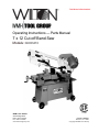
Operating Instructions — Parts Manual
7 x 12 Cut-off Band Saw
Models: 3400/3410
WHM TOOL GROUP
2420 Vantage Drive
Elgin, Illinois 60124
Ph.: 800-274-6848
www.wmhtoolgroup.com
177339
Part No. 9078201
Revision A7 10/06
Copyright © WMH Tool Group
Warranty and Service
WMH Tool Group, Inc., warrants every product it sells. If one of our tools needs service or repair, one of our Authorized Service Centers
located throughout the United States can give you quick service. In most cases, any of these WMH Tool Group Authorized Service
Centers can authorize warranty repair, assist you in obtaining parts, or perform routine maintenance and major repair on your
WILTON® tools. For the name of an Authorized Service Center in your area call 1-800-274-6848.
MORE INFORMATION
Group distributor, or visit wiltontool.com.
WARRANTY
WILTON products carry a limited warranty which varies in duration based upon the product. (MW = Metalworking)
WHAT IS COVERED?
This warranty covers any defects in workmanship or materials subject to the exceptions stated below. Cutting tools, abrasives and
other consumables are excluded from warranty coverage.
WHO IS COVERED?
This warranty covers only the initial purchaser of the product.
WHAT IS THE PERIOD OF COVERAGE?
The general WILTON warranty lasts for the time period specified in the product literature of each product.
WHAT IS NOT COVERED?
This warranty does not cover defects due directly or indirectly to misuse, abuse, negligence or accidents, normal wear-and-tear,
improper repair or alterations, or lack of maintenance.
HOW TO GET SERVICE
The product or part must be returned for examination, postage prepaid, to a location designated by us. For the name of the location
nearest you, please call 1-800-274-6848.
You must provide proof of initial purchase date and an explanation of the complaint must accompany the merchandise. If our inspection
discloses a defect, we will repair or replace the product, or refund the purchase price, at our option.
We will return the repaired product or replacement at our expense unless it is determined by us that there is no defect, or that the defect
resulted from causes not within the scope of our warranty in which case we will, at your direction, dispose of or return the product.
In the event you choose to have the product returned, you will be responsible for the handling and shipping costs of the return.
HOW STATE LAW APPLIES
This warranty gives you specific legal rights; you may also have other rights which vary from state to state.
LIMITATIONS ON THIS WARRANTY
WMH TOOL GROUP LIMITS ALL IMPLIED WARRANTIES TO THE PERIOD OF THE LIMITED WARRANTY FOR EACH PRODUCT. EXCEPT AS
STATED HEREIN, ANY IMPLIED WARRANTIES OR MERCHANTABILITY AND FITNESS ARE EXCLUDED. SOME STATES DO NOT ALLOW
LIMITATIONS ON HOW LONG THE IMPLIED WARRANTY LASTS, SO THE ABOVE LIMITATION MAY NOT APPLY TO YOU.
WMH TOOL GROUP SHALL IN NO EVENT BE LIABLE FOR DEATH, INJURIES TO PERSONS OR PROPERTY, OR FOR INCIDENTAL,
CONTINGENT, SPECIAL, OR CONSEQUENTIAL DAMAGES ARISING FROM THE USE OF OUR PRODUCTS. SOME STATES DO NOT
ALLOW THE EXCLUSION OR LIMITATION OF INCIDENTAL OR CONSEQUENTIAL DAMAGES, SO THE ABOVE LIMITATION OR EXCLUSION
MAY NOT APPLY TO YOU.
WMH Tool Group sells through distributors only. The specifications in WMH catalogs are given as general information and are not
binding. Members of WMH Tool Group reserve the right to effect at any time, without prior notice, those alterations to parts, fittings, and
accessory equipment which they may deem necessary for any reason whatsoever.
Table of Contents
Cover Page .......................................................................................................................... 1
Warranty ................................................................................................................................ 2
Table of Contents .................................................................................................................. 3
General Specifications .......................................................................................................... 4
Warnings ............................................................................................................................ 5-6
Using the Vise .................................................................................................................... 7-9
Setting Blade Guides ............................................................................................................ 9
Hydraulic Feed Control ........................................................................................................ 10
Using Stock Stop ................................................................................................................. 10
Changing Blade Speeds ..................................................................................................... 11
Blade Selection ................................................................................................................... 11
Evaluating Cutting Eficiency ................................................................................................ 11
Blade Break-in Procedures ................................................................................................. 11
Starting a Cut ...................................................................................................................... 11
Angle Cuts ..................................................................................................................... 12-13
Replacing Blades ................................................................................................................ 14
Adjusting Blade Tracking ..................................................................................................... 14
Blade Alignment Adjustments .............................................................................................. 15
When to Adjust Blade Guides .............................................................................................. 15
Replacing Blade Guides and Support Components ............................................................. 16
Adjust Blade for Parallelism ................................................................................................ 16
Adjusting Blade Vertical ...................................................................................................... 17
Test Cutting to Verify Adjustment Accuracy ........................................................................... 17
Adjusting Guide Bearings .................................................................................................... 18
Replacing Guide Bearings .................................................................................................. 18
Adjusting Blade Back Up Bearing ....................................................................................... 18
Replacing the Drive Wheel .................................................................................................. 19
Installing the Vertical Sawing Table ...................................................................................... 19
Replacing Idler Wheel or Bearings ...................................................................................... 19
Servicing the Hydraulic Control Cylinder .............................................................................. 20
Machine Set-up ................................................................................................................... 21
Uncrating and Spotting the Saw ........................................................................................... 21
Electrical ............................................................................................................................. 21
Changing Operating Voltage ............................................................................................... 21
Installing the Coolant Kit ...................................................................................................... 22
Chip Brush Replacement .................................................................................................... 22
Adjusting Horizontal Stop and Motor Switch ......................................................................... 22
To Replace or Adjust the Horizontal Stop ............................................................................. 22
Adjusting the Motor Switch Actuator..................................................................................... 22
Troubleshooting .............................................................................................................. 23-24
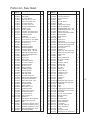
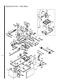
Replacement Parts and Breakdowns ............................................................................. 25-30
3
General
Specifications
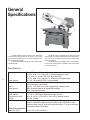
The Wilton Models 3400 and 3410 cut-off band saws
are designed for high production cut-off work. Four cutting
speeds and a hydraulic feed control allows the efficient cutting of virtually any material.
A removable table also allows the saw to function as a
vertical band saw.
The Model 3410 is equipped with an optional coolant
system which can greatly extend blade life and speed the cutting of a variety of materials which are best cut with cutting
fluids and coolants.
The Model 3400 is not equipped with a coolant system.
However, the coolant system is available as an add-on kit for
customer installation.
Specifications:
Cutting capacity
4
Blade speeds
Blade drive
Motor
Blade guides
Blade size
Blade wheels
Dimensions (LWH)
Weight
Wet cutting package
7 in. (178mm) round bar stock or tubing
9 1/2 in. wide x 7 in. high (240 x 178mm) rectangular stock
12 in. wide x 1 in. high (305 x 25.4mm) flat stock
3 3/4 in. wide x 6 in. high (95.3 x 150mm) at 45 degree angle
80, 130, 180 and 265 SFM -- belt selectable
Heat treated steel worm pinion driving a bronze
worm ring gear in an oil bath
3/4 HP, 1725 RPM, 115/230V, single phase, capacitor start
Side: Eccentric shaft with sealed ball bearings
Rear: Sealed ball bearing
3/4 x .032 x 93 in.
11 7/16 in. (280.56mm) diameter flanged cast iron
50 x 18 x 41 in. (1270 x 457 x 1041mm) in lowered position
275 lbs. (125kg)
1 gallon (4.4L) capacity tank with 3GPM (13L/M) pump -- Optional wet kit
Part No. 5635500 includes tank with baffle, pump 120V/240V, hoses,
flexible nozzle, shut-off valve and required electrics. This kit is delivered
installed on Model 3410 saws.
Vertical saw operation
9 1/2 x 10 in. (241 x 254mm)
Table size (LW)
- Misuse of this machine can cause serious injury.
- For safety, machine must be set up, used and serviced
properly.
- Read, understand and follow instructions in the
operator’s and parts manual which was shipped with
your machine.
When setting up machine:
- Always avoid using machine in damp or poorly lighted
work areas.
- Always be sure machine is securely anchored to the
floor.
- Always keep machine guards in place.
- Always put start switch in OFF“ position before
plugging in machine.
When using machine:
- Never operate with machine guards missing.
- Always wear safety glasses with side shields (See
ANSI Z87.1)
- Never wear loose clothing or jewelry.
- Never overreach — you may slip and fall into the
machine.
- Never leave machine running while away from it.
- Always shut off the machine when not in use.
When servicing machine:
- Always unplug machine from electrical power while
servicing.
- Always follow instructions in operators and parts
manual when changing accessory tools or parts.
- Never modify the machine without consulting Wilton
Corporation.
You — the stationary power tool user — hold the
key to safety.
Read and follow these simple rules for best
results and full benefits from your machine. Used
properly, Wilton’s machinery is among the best in
design and safety. However, any machine used
improperly can be rendered inefficient and unsafe. It is
absolutely mandatory that those who use our products
be properly trained in how to use them correctly. They
should read and understand the Operators and Parts
Manual as well as all labels affixed to the machine.
Failure in following all of these warnings can cause
serious injuries.
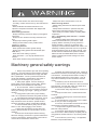
Machinery general safety warnings
1. Always wear protective eye wear when operating
machinery. Eye wear shall be impact resistant, protective
safety glasses with side shields which comply with ANSI
Z87.1 specifications. Use of eye wear which does not
comply with ANSI Z87.1 specifications could result in
severe injury from breakage of eye protection.
2. Wear proper apparel. No loose clothing or
jewelry which can get caught in moving parts. Rubber
soled footwear is recommended for best footing.
3. Do not overreach. Failure to maintain proper
working position can cause you to fall into the machine or
cause your clothing to get caught — pulling you into the
machine.
4. Keep guards in place and in proper working
order. Do not operate the machine with guards removed.
5. Avoid dangerous working environments. Do not
use stationary machine tools in wet or damp locations.
Keep work areas clean and well lit. Special electrics
should be used when working on flammable materials.
6. Avoid accidental starts by being sure the start
switch is OFF” before plugging in the machine.
7. Never leave the machine running while unattended. Machine shall be shut off whenever it is not in
operation.
8. Disconnect electrical power before servicing.
Whenever changing accessories or general maintenance
is done on the machine, electrical power to the machine
must be disconnected before work is done.
9. Maintain all machine tools with care. Follow all
maintenance instructions for lubricating and the changing
of accessories. No attempt shall be made to modify or
have makeshift repairs done to the machine. This not
only voids the warranty but also renders the machine
unsafe.
10. Machinery must be anchored to the floor.
11. Secure work. Use clamps or a vise to hold work,
when practical. It is safer than using your hands and it
frees both hands to operate the machine.
12. Never brush away chips while the machine is in
operation.
13. Keep work area clean. Cluttered areas invite
accidents.
14. Remove adjusting keys and wrenches before
turning machine on.
15. Use the right tool. Don't force a tool or attachment to do a job it was not designed for.
16. Use only recommended accessories and follow
manufacturers instructions pertaining to them.
17. Keep hands in sight and clear of all moving
parts and cutting surfaces.
18. All visitors should be kept at a safe distance
from the work area. Make workshop completely safe by
using padlocks, master switches, or by removing starter
keys.
19. Know the tool you are using — its application,
limitations, and potential hazards.
5
20.Some dust created by power sanding, sawing,
grinding, drilling and other construction activities
contains chemicals known to cause cancer, birth
defects or other reproductive harm. Some examples of
these chemicals are:
Lead from lead based paint
crystalline silica from bricks and cement and other
masonry products, and
arsenic and chromium from chemically-treated
lumber.
21.Your risk from those exposures varies, depending on how often you do this type of work. To reduce your
exposure to these chemicals: work in a well ventilated
area, and work with approved safety equipment, such as
those dust masks that are specifically designed to filter
out microscopic particles.
Conductor length
0-50 feet
50-100 feet
Over 100 feet
General Electrical Cautions
This saw should be grounded in accordance with
the National Electrical Code and local codes and
ordinances. This work should be done by a qualified
electrician. The saw should be grounded to protect the
user from electrical shock.
Wire sizes
Caution: for circuits which are far away from the
electrical service box, the wire size must be increased
in order to deliver ample voltage to the motor. To
minimize power losses and to prevent motor overheating and burnout, the use of wire sizes for branch
circuits or electrical extension cords according to the
following table is recommended:
AWG (American wire gauge) number
240 volt lines
120 volt lines
No. 14
No. 14
No. 14
No. 12
No. 12
No. 8
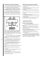
Safety instructions on sawing systems
6
1. Always wear leather gloves when handling
saw blade. The operator shall not wear gloves when
operating the machine.
2. All doors shall be closed, all panels replaced,
and all other safety guards in place prior to the machine
being started or operated.
3. Be sure that the blade is not in contact with the
workpiece when the motor is started. The motor shall
be started and you should allow the saw to come to full
speed before bringing the workpiece into the saw blade.
4. Keep hands away from the blade area. See
figure A.
5. Remove any cut off piece carefully while
keeping your hands free of the blade area.
6. Saw must be stopped and electrical supply
must be cut off before any blade replacement or
adjustment of blade support mechanism is done, or
before any attempt is made to change the drive belts or
before any periodic service or maintenance is performed on the saw.
7. Remove all loose items and any unnecessary
work pieces from the area before starting machine.
8. Bring adjustable saw guides and guards as
A
B
close as possible to the work piece.
9. Always wear protective eye wear when
operating, servicing or adjusting machinery. Eyewear
shall be impact resistant, protective safety glasses with
side shields complying with ANSI Z87.1 specifications.
Use of eye wear which does not comply with ANSI
Z87.1 specifications could result in severe injury from
breakage of eye protection. See figure B.
10. Non-slip footwear and safety shoes are
recommended. See figure C.
11. Wear ear protectors (plugs or muffs) during
extended periods of operation. See figure D.
12. The workpiece, or part being sawed, must be
securely clamped before the saw blade enters it.
13. Remove cut off pieces carefully, keeping
hands away from sawblade.
14. Saw must be stopped and electrical supply
cut off or machine unplugged before reaching into
cutting area.
15. Avoid contact with coolant, especially
guarding your eyes.
C
D
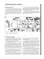
Operating Instructions
Using the vise
The vise on the saw table has two jaws. The jaw
closest to the right hand side of the table is the stationary
jaw. This jaw is firmly secured to the table using its pivot
and lock bolts. When making a straight cut the stationary
jaw is at right angles to the saw blade. When making an
angle cut, the stationary jaw is first loosened, then
adjusted to the desired angle, then secured to the table,
again.
The jaw closest to the left hand side of the table is
the locking jaw. This jaw clamps the workpiece against the
stationary jaw to hold it securely for cutting. The locking
jaw can pivot to conform to the angle of the work piece
which is held in the stationary jaw.
Before cutting can begin, the vise must be properly
set and positioned. The procedures are different for right
angle cutting and for angle cutting. Setting procedures are
given in the following sections.
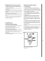
Figure 1: Vise jaw nomenclature
Locking vise jaw
The locking jaw is an assembly which includes the
lead screw nut which encases the lead screw, the lead
screw shaft (which screws into the lead screw nut,) the
thrust shaft, spring, and quick release handle.
The thrust shaft moves up or down when the quick
release handle moves up or down.
The thrust shaft has a nut under the quick release
handle which adjusts the clamping pressure between the
adjustable jaw and the table, itself. When this nut is too
tight, the adjustable jaw cannot pivot. When this nut is too
loose, the jaw can pivot, and also tilt upward. Therefore,
this nut should be slightly loose. This will allow the jaw to
pivot an conform to any angle at which the stationary jaw
is set.
However, you should guard against excessive
loosening of this nut. If too loose, the jaw can tilt when it
contacts the workpiece and full clamping pressure cannot
be effectively applied to the workpiece.
If the shaft is too tight to allow pivoting of the jaw,
loosen the shaft slightly by turning the nut under the quick
release handle counterclockwise. If the jaw tilts exces-
sively, use the nut under the quick release handle to
tighten the shaft slightly so the jaw slides easily, but flat
against the saw table.
The locking vise jaw is tightened or loosened against
the workpiece being cut by using the lead screw handle.
The handle is attached to a lead screw underneath the saw
table. The lead screw has a series of grooves on its
length. These grooves capture a thrust shaft on the lower
side of the locking jaw. As the lead screw handle is turned,
the grooves move to the left or right, and therefore the
locking jaw is moved to the left or right to open or close the
jaw against any workpiece on the table.
The thrust shaft on the locking vise jaw is a component part of the quick release handle on top of the locking
jaw. This quick release handle is spring loaded to force the
handle (and, therefore, the thrust shaft) downward.
When you pull up on the quick release handle, the
thrust shaft is removed from its groove. This allows you to
slide the jaw to a new position on the table. Releasing the
handle pushes the thrust shaft against the lead screw
shaft. When the lead screw handle is turned, a groove will
7
eventually catch the thrust shaft and allow you to open or
close the locking jaw at its new lead screw position.
When you slide the jaw to a new position, you can
see where the nearest lead screw groove is by looking
through the slot above the lead screw. (See Figure 1.)
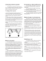
Changing the locking
jaw location:
1. Lift the quick release handle.
2. Slide the jaw until it contacts the workpiece.
3. Turn the lead screw handle until the thrust shaft drops
into a groove.
4. Further turning of the lead screw handle will either
clamp or release the workpiece in the vise. Turn
clockwise to increase clamping pressure. Turn
counterclockwise to release clamping pressure.
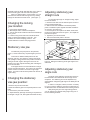
Adjusting stationary jaw:
straight cuts
For accurate right angle or "straight" cutting, adjust
the vise as follows:
1. Disconnect the saw from its electrical power source to
prevent accidental start-ups.
2. With the saw arm and blade in horizontal position,
place a machinist's square against the blade and stationary vise jaw. (See Figure 2.)
3. If the vise jaw is not square to the blade, loosen both
the pivot and lock bolts shown in Figure 1, and adjust the
jaw until it is square.
4. Tighten the pivot and lock bolts.
5. Reconnect electrical power to the saw.
Stationary vise jaw
The stationary vise jaw pivots on the pivot bolt,
Figure 1, and is locked at any required angle by the lock
bolt.
There are two different table positions for the
stationary vise jaw. One position is used for right angle
cuts ("straight" cutting) and the other position is used for
cutting of all other angles. Moving the vise from one
position to the other requires unbolting and re-bolting the
jaw to the saw table.
Four tapped holes in the saw table allow a change
of pivot and lock bolt position. The holes in the right-most
position closest to the motor are used for right angle
cutting. The holes in the left-most position are used for all
angle cutting.
8
Changing the stationary
vise jaw position:
1. Remove the pivot and lock bolts.
2. Slide the stationary jaw to the required position on the
table.
3. Re-insert the pivot and lock bolts.
4. Adjust stationary jaw angle according to requirements
for straight or angle cuts, then tighten both bolts securely.
Figure 2: Setting the stationary jaw at right angles to the
saw blade.
Adjusting stationary jaw:
angle cuts
The angle of the stationary vise jaw with respect to
the saw blade is what determines the cut angle on the
workpiece. The stationary jaw can be adjusted to any
angle between 0 degrees (right angle to the blade) and 45
degrees.
In order to cut angles, however, it will be necessary
for you to move the stationary vise jaw to its left-most set
of attachment holes as described in the following sections.
After placing the jaw in the angle cutting position,
you can adjust to the desired cutting angle using one of
the two following methods.
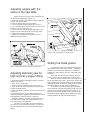
Adjusting angles with the
scale on the saw table
There is a scale on the rear of the saw base which
can be used to establish the angle of cut.
1. Raise the saw arm to full height and lock it in position
with the quick shut-off valve.
2. Slide the locking jaw to full open position.
3. Loosen the pivot and lock bolts shown in Figure 1.
4. Lay a straight edge on the saw frame so it contacts the
stationary vise jaw. (See Figure 3.)
5. Turn the vise jaw until the straight edge is above the
angle of cut you require as shown on the angle gauge.
6. Tighten both the pivot and lock bolts.
7. Remove the straight edge and proceed to cut as
described in Angle sawing.
Figure 4: Using a protractor to set jaw angle
Setting the blade guides
Figure 3: Using table scale to set jaw for angle cuts
Adjusting stationary jaw for
high accuracy angle cutting:
1. Raise the saw arm to full height and lock it in position
with the shut-off valve.
2. Open the vise to full width.
3. Loosen the pivot and lock bolts shown in Figure 1.
4. Open the shut-off valve and lower the saw arm until it
is at full horizontal position.
5. Take a machinist's protractor and set it to the angle you
need to cut.
6. Lay the protractor on the saw table and place one
edge of the protractor against the saw blade and the other
edge against the stationary vise jaw. (Figure 4.)
7. Adjust the stationary vise jaw until its angle is correct
with respect to the blade, then lock the stationary jaw
firmly using the pivot and lock bolts.
The saw is now accurately set to the exact angle
you have set on the machinist's protractor. You can now
saw the workpieces according to instructions on Angle
sawing.
To produce accurate cuts the distance between the
blade guide/supports must be set correctly. Whenever
possible, set the blade guide assembly so it clears the
workpiece by approximately 1/8 inch on either side of the
workpiece.
The guides may be moved by loosening the lock
handles which secure the bracket bars to the saw arm.
There is, however, a limit to how close the guide can
be set with respect to the table. When set too close to the
blade clearance slot, the guide bearings can hit the table
casting and prevent the arm from moving to full horizontal.
When this happens, the saw cannot complete its cut.
This won't be a problem with the right-hand guide.
On the other hand, the left-hand guide typically cannot be
much closer to the right-hand guide than 6 inches or so.
Therefore, when cutting smaller section material, be sure
the blade is correctly adjusted, tensioned properly, sharp,
and appropriate to the type of material being cut.
9
Controlling the cut:
Hydraulic feed control
10
The weight of the saw arm typically provides all of
the force needed to move the saw blade through the
workpiece. In fact, if the full weight of the arm is allowed
to make the cut, rapid blade wear and poor cutting
accuracy will result. Therefore, a hydraulic feed control is
provided which gives the operator control over the speed
and efficiency of cutting.
The hydraulic feed control is a single-acting
hydraulic cylinder attached between the saw base and
saw arm. The hydraulic control cylinder has two flow
controls. The control needle valve -- used by the operator
to control the rate of cutting -- is on top of the cylinder. A
quick shut-off valve is located in a hydraulic line on the
outside of the cylinder.
The control cylinder is single-acting because it can
be used to resist motion in the downward direction, only.
The control cylinder offers no resistance to upward
movement.
The amount of downward force can be controlled by
using the needle valve on top of the cylinder. When the
needle valve is closed the cylinder is "locked." With the
needle valve open slightly, the cylinder permits slow, or
light downward force. As the needle valve is opened
further, increasing weight of the saw arm presses on the
blade and workpiece.
The needle valve is opened, during any cut, until the
operator determines that the saw is operating efficiently.
This is usually evaluated by observing chip formation.
See the section on Blade Selection, for more information
on evaluating cutting efficiency.
The quarter-turn quick shut off valve in the external
line of the control cylinder can be turned to lock the
cylinder at any time. For instance, it can be used to lock
the blade above the work piece to allow you to measure
the length of cut on the workpiece. Or, it can be used for
making repeated cuts after the needle valve has been set
for best cutting efficiency. (This is described in the next
section.)
To close the hydraulic control circuit and lock the
cylinder, turn the quick shut off valve handle so it is at
right angles to the hydraulic line or hydraulic cylinder.
To open the hydraulic control circuit and return feed
control to the needle valve, turn the quick shut off handle
so it is parallel with the hydraulic line or hydraulic cylinder.
Figure 6: Using the stock stop
Using the stock stop
for repeated cuts
If you are cutting multiple pieces of stock, all to the
same specified length, use the stock stop.
1. Lower the saw arm to its horizontal position.
2. Loosen the stock stop set screws as necessary to slide
the stop upward and more-or-less into position.
(There are two set screws which are use to lock the stop
stock in position. One is on the saw table and is typically
used to adjust the distance between the stop and the
blade. The other set screw is on the stop, itself, and is
typically used to adjust the height of the stop above the
table. However, you can use any combination of set
screws you find convenient to adjust the stop to the
distance and height which works for the stock you are
cutting.)
3. Using a ruler or scale, measure the distance between
the blade and stock stop.
4. When the correct cut-off distance is obtained, be sure
the stock stop is at a position which allows the cutoff
piece to fall away from the blade as the cut is completed.
Then, tighten the stock stop set screws securely.
5. Raise the saw arm.
6. Place a workpiece in the saw vise and slide the
workpiece so it contacts the stock stop.
7. Open the hydraulic control cylinder quick shut off valve
and move the saw blade to just above the workpiece then close the needle valve so the arm is locked in
position.
8. Measure the distance between the end of the
workpiece and the blade to verify that you have set the
stock stop at the correct distance. (See Figure 6.)
9. When you are satisfied that your cut-off distance is
correct, you may begin cutting by turning on the saw and
opening the needle valve until the blade is cutting
efficiently.
To continue making multiple cuts take the following steps:
1. Do not change the setting on the needle valve.
2. Raise the saw arm so it clears the stock being cut and
lock the hydraulic control cylinder using the quick shut off
valve.
3. Release the vise slightly using the handle wheel -move the stock up to the stock stop -- tighten the vise
again.
4. Turn on the saw and open the quick shut off valve.
Because you established an efficient cutting rate on the
previous cuts using the needle valve, there is no reason to
change its setting. The quick shut off, alone, can be used
to begin and complete the cut.
Changing blade speeds
The Models 3410 and 3400 are 4-speed cut-off
saws. The different speeds are obtained by changing the
position of the drive V-belt which connects the motor
pulley to the drivewheel gearbox pulley.
To change blade speeds:
1. Disconnect the saw from its electrical power source to
prevent any possibility of accidental motor start-up.
2. Allow the saw arm to rest at its full horizontal position.
3. Open the pulley cover to expose the V-belt and
pulleys.
4. Loosen the motor plate lock bolt jam nut and lock bolt.
5. Loosen the jam nuts on the motor plate adjustment
bolts, then loosen the motor plate adjustment bolts so the
motor can slide on its mounting plate to where the V-belt
can be removed from the pulleys.
6. Put the V-belt in the pulley position for the speed you
require --- refer to Figure 7 for belt locations and speeds
available.
7. Tension the belt by adjusting the motor adjustment
bolts until the V-belt has one belt's width of slack when
pressed firmly in the center of its travel.
8. Reverse steps 1 through 5, above, to complete the
speed change.
265 SFM
180 SFM
130 SFM
80 SFM
Gearbox
Motor
Evaluating cutting efficiency
Is the blade cutting efficiently? The best way to
determine this is to observe the chips formed by the
cutting blade.
If the chip formation is powdery, then the feed is
much too light, or the blade is too dull.
If the chips formed are curled, but colored -- that is,
either blue or straw colored from heat generated during
the cut -- then the feed rate is too high.
If the chips are slightly curled and are not colored by
heat -- the blade is sufficiently sharp and is cutting at its
most efficient rate.
Blade break-in procedures
New blades are very sharp and, therefore, have a
tooth geometry which is easily damaged if a careful breakin procedure is not followed. You may want to consult
manufacturers' literature for break-in of specific blades on
specific materials. However, the following procedure will
be adequate for break-in of Wilton supplied blades on
lower alloy ferrous materials.
1. Clamp a round section work piece in the vise. The
work piece should be 2 inches or larger in diameter.
2. With the saw on low speed, begin the cut with a very
light feed rate.
3. After the saw has completed 1/3rd of the cut, increase
the feed rate slightly and allow the saw to complete the
cut.
4. Without disturbing the position of the needle valve,
begin a second cut on the same or similar work piece.
5. After the blade has completed about 1/3rd of the cut,
increase the rate of feed and observe chip formation until
cutting is at its most efficient rate (see Evaluating blade
efficiency, above) ...then allow the saw to complete the
cut. The blade can now be considered ready for regular
service.
Figure 7: Belt position/speed relationships
Blade selection
The saw is delivered with a blade adequate for a
variety of cut-off jobs on a variety of common materials.
Wilton also can provide you with other blades. See the
parts listings for available blade types. See Table 1, for
some recommended speeds for various materials.
However, these selections, while appropriate to the many
of shop cutting needs, don't begin to exhaust the wide
variety of blades of special configuration (tooth pitch and
set) and special alloys for cutting unusual or exotic
materials.
For very high production on cutting of special
materials, or to cut hard-to-cut materials such as stainless
steel, tool steel, titanium, etc., you can ask your industrial
distributor for more specific blade recommendations.
Also, the supplier who provides the workpiece material
should be prepared to provide you with very specific
instructions regarding the best blade (and coolant or
cutting fluid, if needed) for the material or shape supplied.
Starting a cut
To avoid blade damage, follow these procedures:
1. Never start a cut with the blade resting on the
workpiece.
2. Never start a cut on a sharp edge. If the workpiece
has a sharp edge, use a file to knock off the sharp edge
before lowering the blade onto the workpiece.
3. Have the motor on and running at full speed before
cutting.
4. Use the hydraulic control cylinder needle valve to
begin the cut of any single piece (although succeeding
pieces of the same type can be started using the quick
shut off valve.)
5. If you use coolant or cutting fluid, turn on the flow of
coolant before starting a cut.
11
Right angle cuts -single pieces of stock
1. Raise the saw arm to its full up, open position.
2. Pull up on the quick release handle on the locking vise
jaw and slide the vise jaws apart.
3. Place the stock on the saw table, between the vise
jaws. If the stock is long, support the stock with
appropriate infeed and outfeed supports.
4. Pull up on the quick release handle and slide the
locking vise jaw up against the workpiece.
5. Turn the lead screw handle until the quick release
thrust shaft falls into a groove on the lead screw and puts
light clamping pressure on the workpiece.
6. Lower the saw arm until the blade is just above the
workpiece.
7. Lock the saw arm in position by turning the hydraulic
feed needle valve clockwise.
8. Adjust the position of the stock until the cut-off distance
you require is directly under the blade.
9. Tighten the vise so the workpiece is clamped firmly.
Note: if you are sawing a workpiece with a sharp
edge up -- use a file to knock off the sharp edge before
beginning any saw cuts. This will prevent damage to
teeth on the blade. See Figure 8 for details.
10. Turn the saw switch ON and allow the motor and
blade to come up to full speed.
11. If using a coolant system, turn on the valve at the
nozzle.
12. Carefully open the hydraulic control needle valve open
(counterclockwise) so the cutting arm lowers gently into
the workpiece and begins cutting.
13. Continue to open the hydraulic control valve until an
efficient cutting rate is established.
14. When the saw completes its cut, the motor will shut
off and the cut piece will fall away from the table.
15. If you are using a coolant system, turn it off the valve
at the nozzle.
12
Table 1: Suggested cutting speeds
Suggested cutting speeds for a variety of materials.
Speeds are recommended speeds for a 4 inch thick work
piece, a bi-metal blade, dry cutting. (No cutting fluid.
Speeds may be increased when cutting fluid is used -observe chip formation to determine most efficient cutting
rate.)
Decrease these speeds 30-50% for carbon steel blades.
Increase speed 15% for materials 1/4 inch thick, 12% for
materials 3/4 inch thick, 10% for materials 1 1/4 inch thick,
and 5% for 2 1/2 inch thick material. Decrease speed
12% when cutting eight inch material. When selecting
blade tooth pitch, be sure to have two or more teeth in
contact with the material at all times to avoid tooth
breakage.
Angle cutting
1. Raise the saw arm to full height and lock it in position
with the quick shut off valve.
2. Slide the vise open.
3. Set the stationary vise jaw to the angle required
according to the instructions in Adjusting stationary vise
jaw.
4. Put the workpiece in position on the saw table.
5. Adjust the locking vise jaw to the workpiece using
instructions in Adjusting the locking jaw.
6. Adjust the blade guide/support bearing brackets
according to instructions in Setting the blade guides.
7. Release the quick shut off valve and lower the arm and
blade to just above the workpiece, then lock the arm in
position using the hydraulic cylinder control needle valve.
8. Adjust the workpiece to the required cut-off position
under the blade.
9. Tighten the vise securely.
10. If you are starting your cut on a sharp edge, use a
file to knock off the sharp edge so the blade isn't damaged
at the start of the cut.
11. If using coolant or cutting fluid, turn on valve at the
nozzle.
12. Turn the saw switch ON.
13. Open the hydraulic cylinder needle valve until the
blade contacts the workpiece and establishes a cut -- then
open the control cylinder valve until the blade is cutting
efficiently.
14. When the cut is completed the motor will turn off and
the cut piece will fall away from the saw. Turn off the
coolant flow and repeat the steps above as necessary to
continue with more cuts.
Note: the stock stop can be used for multiple angle cuts in
the same way as described for straight cuts. See Using
the stock stop for repeated cuts.
Material
Structural steel shapes
Low carbon steel
Medium carbon steel
High carbon steel
Cr-moly steel
Ni-Cr-moly steel
Chromium steel
Cr-vanadium steel
Tool steel
Stainless steel
Free machining steel
Cast iron
Copper alloy (CU-Zm)
Bronze
Al-bronze
Monel
Titanium alloy
Aluminum (T-6+)
Speed
165
160-165
115
90-100
105-135
90-115
80-140
105-115
40-80
40-70
80-100
55-90
55
90
40
40-45
25-40
80-160
Figure 8: Placing workpieces in the vise
13
Maintenance
Replacing blades
1. Disconnect the saw from its electrical power source to
prevent accidental start-ups.
2. Raise the saw arm to its full vertical position and lock it
in place using the quick shut off valve on the hydraulic
control cylinder.
3. Lift the safety cover in the lower portion of the blade
guard door by sliding it upward. There is no need to
remove it completely from its slot.
4. Remove the two screws with plastic knobs which hold
the blade guard door closed and swing the door open to
expose the drive and idler wheels, and the blade.
5. Turn the blade tension handle counterclockwise until
the blade hangs loose in the saw arm.
6. Use leather gloves to prevent cuts and scratches and
use protective eyewear which meets ANSI Specification
Z87.1. and pull the blade off of the drive wheels and out of
the blade guides. Store the blade carefully before
proceeding.
7. Slide the new blade into the blade guides -- then loop
the blade over the upper and lower drive wheels.
Note: it is possible to install the blade backwards. The
teeth on the blade should be pointing downward, toward
the motor, at the time the blade is installed.
14
8. Push the blade so it is seated against the shoulders of
the wheels. When it is seated against the shoulders...
9. ...turn the blade tension wheel clockwise to increase
tension on the blade. Don't over-tension the blade.
Tension it enough so it doesn't slip while cutting.
10. When you are satisfied that the saw is tensioned
correctly, reconnect the saw to its electrical power source.
11. Check the tracking of the blade according to
instructions in the section on Adjusting blade tracking,
below.
12. Close the wheel guard door and secure it using the
two plastic knobbed screws.
13. Slide the safety cover downward in its slot until it is
fully closed.
14. The new blade is installed and ready for the Blade
break-in procedures.
To adjust blade tracking:
1. Loosen the sliding plate draw block bolt slightly so the
adjustment set screw will be able to move the draw block.
2. Turn the coolant pump switch OFF, if coolant is used.
3. Turn the saw ON.
4. Insert a 4mm hex wrench in the socket head track
adjustment set screw.
5. Turn the track adjustment set screw so the blade starts
to move away from the shoulder -- then immediately turn
the screw the other direction so the blade stops -- then
moves slowly toward the shoulder.
6. Use the blade tracking adjustment screw to stop the
motion of the blade on the wheel as it gets close to the
shoulder. Now, put a strip of paper between the blade and
wheel as shown in Figure 9. KEEP FINGERS CLEAR OF
THE BLADE AND WHEEL. (That's why the paper strip
should be at least 6 inches long.)
7. The paper should not be cut, this first attempt. Next,
turn the track adjustment set screw a tiny amount more
and repeat the insertion of the paper between the blade
and wheel.
You may have to repeat this step several times before the
blade and shoulder cut the paper into two pieces. Don't
be in a hurry. Patience and accuracy here will pay off with
better, more accurate, quieter cutting and much longer
machine and blade life.
8. When the paper is cut, turn the adjustment screw
counterclockwise, slightly. This assures that the blade is
not touching the shoulder of the wheel.
9. Tighten the two bolts which hold the draw block.
Adjusting blade tracking
If the blade is fully tensioned, release tension
slightly before attempting to adjust the saw blade tracking.
A badly worn or bent blade will be extremely difficult to
track properly -- if it can be tracked successfully, at all.
The track of the saw blade is adjusted using the track
adjustment mechanism on the idler wheel. The track
adjustment tilts the wheel to "steer" the blade on the
wheels. Tracking adjustment is performed with the saw
arm in vertical position, blade guard doors open and the
saw running. Therefore, USE EXTREME CAUTION
WHEN PERFORMING BLADE TRACKING CHECKS AND
ADJUSTMENTS.
Figure 9: Inserting the paper strips between the blade
and wheel to adjust blade-to-shoulder clearance
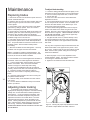
Blade alignment adjustments
The blade can suffer from several out-of-adjustment
conditions. These conditions are shown in Figure 10.
Figure 10: Blade alignment fault conditions
Establishing a reference surface for blade adjustment
So long as major changes and adjustments to the
blade guide system are not made, you will not have to
perform the following procedure. However, assuming the
"worst possible case" -- someone dismantles all of the
guides and components -- here is how to determine a
baseline reference surface for subsequent blade guide
system adjustments.
1. Disconnect the saw from its electrical power source to
prevent accidental start-ups.
2. Be sure the blade is fully tensioned and in good
condition. Use of a new blade is best for this operation.
3. Remove the blade guide, brackets, and all blade
guiding and supporting components which normally
capture and guide the blade at the cutting postion.
4. Lower the saw arm to full horizontal position.
5. Place a machinists square against the blade and
adjust the stationary vise jaw so it is at right angles to the
blade.
6. You have established a reference surface at the
stationary vise face. All subsequent adjustments of blade
parallelism and vertical can be made using the stationary
vise face or the saw table.
When to adjust the
blade guides
The blade guides, when installed at the factory,
have been adjusted for maximum sawing effectiveness
and, if not disturbed, damaged or worn, should require no
field adjustment other than moving the guide brackets as
needed to clear the workpieces being sawed.
However, if the components get out of alignment or
need replacement the following instructions give you the
complete method for adjusting the system.
In particular, there five planes, angles or clearances
which need to be considered.
1. The blade must run parallel to the saw blade clearance
slot. (See Figure 10.)
2. The blade must be square with the vise jaws. (See
Figure 2.)
3. The blade must the vertical and square with respect to
the saw table and must not be twisted. (See Figure 10.)
4. The guide bearings must provide the correct side
clearance and support for the blade.
5. The blade back-up bearing must be correctly placed
behind the blade.
As we say, so long as no component relationships
are disturbed, the factory settings should be adequate to
your tasks. However, parts wear or damage does occur.
When parts are replaced, adjustment of the blade
positioning will almost certainly be necessary.
Of course, regardless of whether or not a component has been disturbed or replaced, at any time you are
not getting the cutting action or accuracy you expect, or
whenever the troubleshooting chart recommends it, you
can and should check the blade support components.
15
Figure 11: Nomenclature for blade guide assembly and its
components
Replacing blade guide
and support components
All component parts are secured with nuts, bolts,
washers, or snap rings. To remove and replace any
component, first remove the blade according to instructions in Replacing blades. Then remove and replace the
faulty component(s).
The guide and support bearings are mounted on
eccentric shafts to permit adjustment of the bearing axis.
See Figure 11. By loosening the eccentric lock nuts and
using a wrench to turn the eccentric, all clearances and
positions can be adjusted.
Replacing a blade guide bearing is covered in the
section on Replacing guide bearings.
In the case of replacing a single faulty component
(such as a single bearing or pair of bearings on an
eccentric) you do not necessarily have to adjust all of the
other components -- however, their adjustment should be
checked when any other adjustment is made.
Before making any adjustments be certain to
disconnect the saw from its electrical power source to
prevent accidental motor start-ups.
parallel to the stationary jaw, no further parallelism
adjustment is required. However, if the blade is at an
angle to the jaw, determine which bearing set you are
going to move and the direction in which you need to
move it. Then proceed to the following steps.
4. Keep the bearing eccentric from moving by putting a
wrench on the adjustment tang of the eccentric. (See
Figure 12.)
5. Loosen the eccentric lock nut so you can rotate the
eccentric using the adjustment tang.
6. Turn the eccentric until you have shifted the bearing
assembly to where you want it to move.
7. Tighten the eccentric lock nut.
8. Adjust the bearing on the other side of the blade so the
bearing clearance adjustment is correct. YOU MUST
PERFORM THIS STEP. The blade is being twisted by the
bearing assemblies and a lot of pressure is being exerted
by the blade against the bearings. See Adjusting guide
bearings.
9. Check the blade for squareness and vertical and readjust as necessary until it is parallel to the clearance slot,
square to the vise jaw, vertical to the table, with side guide
bearings correctly adjusted.
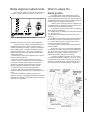
Adjust blade for parallelism:
1. Use a new blade or a blade in nearly new condition and
have it fully tensioned and tracking correctly before
making any adjustments.
2. Be sure the stationary vise jaw is at a right angle to the
blade. If you are not certain the jaw is correctly adjusted,
use the procedure under Establishing a reference angle,
to be sure the jaw is correctly set.
3. Lower the saw arm to full horizontal position.
4. Use a machinist's protractor against the stationary vise
jaw and check the blade for parallel. If the blade is
16
Figure 12: Adjusting blade parallelism using the support
bearing eccentrics. Use two wrenches -- one to lock and
unlock the lock nut, the other to adjust the bearings using
the tang on the guide bearing shaft.
Adjusting blade vertical:
The blade guide bearing seat can rotate as needed to
make the blade vertical to the saw table. Follow these
instructions.
1. With the saw arm in horizontal position, put a
machinists square on the table, and against the blade, as
shown. The blade should be square (vertical) to the table.
If not...
2. Slightly loosen the socket head cap screw which
secures the bearing seat to the bracket bar.
3. Use a wrench to rotate the seat until the blade is
vertical. (See Figure 13.)
4. Tighten the socket head cap screw securely.
5. Check the other blade guide for vertical. Adjust, if
necessary.
6. After adjusting for vertical, RECHECK THE BLADE
FOR PARALLEL. Changes in vertical can easily result in
changes in parallelism. See Adjusting blade parallelism.
Test cutting to verify
adjustment accuracy
Test cuts can be used to determine whether or not
you have adjusted the blade accurately. Use 2 inch bar
stock to perform these test cuts, as follows:
1. With the bar stock securely clamped in the vise, make
a cut through the bar stock. (See Figure 14.)
2. Mark the top of the bar stock.
3. Move the bar stock about 1/4 inch past the blade so
you can begin a second cut.
4. Rotate the bar stock 180 degrees so the mark you
made is now at the bottom of the cut.
5. Make a cut through the bar stock.
6. Use a micrometer to measure the thickness variation
between the top and bottom of the disc you have cut from
the bar stock. Unless things are truly perfectly aligned,
there is almost certain to be a certain amount of "wedge"
to the shape of the disc you have cut. The saw blade can
be considered correctly adjusted when the variation
measured is no more than .012 inch across the face of the
disc.
If you do not have a 2 inch bar stock available for a
test cut, use a larger diameter test work piece rather than
a smaller one. The maximum thickness variation on any
test piece should be no more than .003 inches, per side,
per inch of stock diameter.
Figure 13: Adjusting blade vertical
17
Figure 14: Step-by-step method to produce a test disc
which can be measured for "wedge" - a measurement for
testing cutting accuracy.
Adjusting guide bearings
Replacing guide bearings
There are eight side blade guide/support bearings.
These bearings are installed in the bearing seat, and the
seat is attached to the sliding adjustment bracket.
These bearings are stacked, with two bearings on
each adjustment eccentric. The width of each pair of
stacked bearings is slightly less than the width of a blade.
The force against each of the bearings in each
stack is not equal. This is because the bearings are
twisting the blade. This puts a much higher force against
the two bearings which are doing most of the twisting.
Look at Figure 15 for a diagram which shows this effect.
1. Remove the blade as outlined in steps 1 through 6 of
Replacing blades.
2. Remove the jam nut on the eccentric upon which you
are going to replace bearings.
3. Remove the clip which secures the bearings on the
eccentric shaft.
4. Tap the old bearings off and press the new bearings
on.
5. Replace the snap ring which secures the bearings on
the eccentric.
6. Reinstall the eccentric in its position and tighten the
jam nut loosely on the eccentric.
7. Install the blade according to instructions 7 through 14
in Replacing blades.
8. Adjust bearing clearance according to instructions in
the previous section: Adjusting guide bearings.
Adjusting blade
back-up bearings
Figure 15: Guide bearing forces. Blade twist and clearance is exaggerated for demonstration. In practice, the
blade will be standing vertical between the bearings when
they are adjusted correctly.
18
The bearings are adjusted by moving the eccentrics
as required, and by using your fingers to twist the bearings to see if they can rotate, and how difficult it is to
rotate them.
The bearing clearance is correctly adjusted when
the bearings labeled with an "A" in Figure 15 cannot be
turned at all, and when bearings labeled with a "B" in
Figure 15 can barely be turned with your fingers.
If the supporting bearings don't turn at all -- the setup is too tight. If they can be turned easily using your
thumb and forefinger -- the set-up is too loose.
To adjust:
1. Put a wrench on the adjustment tang of the bearing set
you want to adjust. This prevents the eccentric from
turning.
2. Use another wrench to loosen the lock nut for the
eccentric bolt.
3. Turn the eccentric using the adjustment tang to loosen
or tighten the bearing set, as needed.
4. Tighten the jam nut.
5. Check bearing tightness on both sides of the blade.
Re-adjust as required until the conditions described in the
above paragraphs is obtained.
The back-up bearings support the rear of the saw
blade as it takes the pressure of cutting. (Refer to
Figure 11.)
1. Being careful not to disturb the vertical angle of the
guide bearing seat, loosen the socket head cap screw
which secures the seat.
2. Move the seat downward until the back-up bearing just
barely touches the back of the blade.
3. Tighten the socket head cap screw securely.
4. Perform this same operation on the other back-up
bearing, if required.
After adjusting the back-up bearings, CHECK FOR
BLADE VERTICAL according instructions in Adjusting
blade vertical. It is very easy to disturb the vertical plane
of the blade while performing this adjustment, and a blade
which is not vertical will NOT cut straight.
Replacing the drive wheel
1. Complete steps 1 through 6 in Replacing blades.
2. Remove the snap ring which secures the lower wheel
to the gearbox output shaft.
3. Pull the wheel off of the gearbox output shaft using a
suitable puller.
4. Inspection: Examine the wheel for damage on its drive
edge, shoulder, or the shaft boss. Replace if any faults
are found.
5. Reinstall the wheel by pressing and/or tapping it back
onto the shaft using a soft-faced mallet.
6. Reinstall the snap ring which retains the wheel on the
shaft.
7. Complete steps 7 through 14 of Replacing blades and
any steps in Adjusting blade tracking, as needed to
complete the installation.
Installing the
vertical sawing table
1. Disconnect the saw from its electrical power source to
prevent accidental motor start-ups.
2. Raise the saw to full vertical position and lock in
position using the quick lock valve.
3. Remove the two flat head cap screws which hold the
small cutting plate to the bearing seat.
4. Place the large vertical cutting plate in position and use
the two flat head cap screws to attach it firmly to the
bearing seat.
5. Reconnect the saw to electrical power and it is ready to
use as a vertical band saw.
Replacing idler wheel
or bearings
1. Complete steps 1 through 6 in Replacing blades.
2. Remove center bolt and washer from the idler wheel.
3. Remove the two bolts which hold the sliding plate draw
block in the sliding plate and remove the wheel and draw
block from the saw as an assembly.
4. Using a suitable puller or press, pull or press the
wheel, complete with bearings, off of the draw block.
5. Using a suitable puller, remove the two bearings from
inside the wheel hub.
6. Inspections: Inspect the bearings for evidence of
leakage and turn them to feel for roughness or other
internal flaws. Replace if leaking or roughness is felt.
Examine the wheel for damage on its drive edge, shoulder, or the bearing mounting boss. Replace if any faults
are found.
7. To install new bearings use a suitable press to press
them in the center of the wheel until the races are flush
with the shoulder inside the wheel hub. (See Figure 17.)
8. Press the bearing and wheel assembly onto the shaft
of the sliding block.
9. Reinstall the washer and bolt which retain the wheel on
the shaft.
10. Reinstall the draw block and wheel assembly to the
saw arm using the bolts to secure it to the plate.
11. Complete steps 7 through 14 of Replacing blades and
any steps in Adjusting blade tracking, as needed to
complete the installation.
19
Figure 17: Idler wheel bearing
configuration
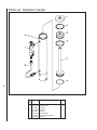
Servicing the hydraulic
control cylinder
20
Over a long period of service the hydraulic control
cylinder may need replacement of its internal seals. Use
the following procedure. (See Figure 18.)
1. Lower the arm to its horizontal position.
2. Remove the upper fasteners, lower set screw, and pin
which secure the cylinder to the saw arm and saw base.
3. Working over a container suitable to hold the fluid, pull
the control rod to its full extended position.
4. Remove the nut on the bottom fitting of the valve and
line assembly. Being careful not to kink the copper line,
remove the end of the line from the fitting in the cylinder.
5. Slowly push the control rod to its fully collapsed
position. This will force most of the hydraulic fluid from
the cylinder.
6. Put the line back into its fitting and tighten its securing
nut.
7. Remove the needle valve assembly from the valve
body.
8. Pull off the plastic cap at the top of the cylinder.
9. Remove the internal snap ring at the top of the
cylinder.
10. Wrap a rag around the top of the cylinder to catch
and cushion the top cap when it is expelled from the
cylinder.
11. Use a source of VERY LOW PRESSURE air and
apply pressure to the needle valve cavity in the valve
body. The top cap will pop out of the cylinder and into the
rag.
12. Remove the lower snap ring from inside the cylinder.
13. Slide the piston assembly from the cylinder, complete.
14. Remove the bottom nut, washer and rubber ring from
the bottom of the piston rod.
15. Remove piston from the rod.
16. Remove the U-ring from the piston.
17. Remove the one external and the two internal O-rings
from the top cap.
Discard all soft parts.
18. Clean all metal parts with a suitable solvent.
19. Use clean hydraulic fluid as a lubricant for all subsequent operations. Install the three O-rings on the top cap
and the U-ring on the piston.
20. Install the piston, U-ring lip down, on the piston rod.
21. Install the rubber ring against the bottom of the piston
and secure it with the washer and nut.
22. Slide the piston assembly into the cylinder. A slight
twisting motion will help ease the U-ring into the cylinder.
Push the piston assembly all of the way to the bottom of
the cylinder.
23. Install the bottom snap ring inside the cylinder.
24. Again working over a container which can catch any
spilled fluid, fill the cylinder with hydraulic fluid until it
comes out the valve body. Use a high quality hydraulic
jack oil for the hydraulic fluid.
25. Install the top cap on the piston rod and slide it into
the cylinder, flush with the bottom snap ring. Again, a
slight twisting motion will help ease the top cap into
positon. You will almost certainly expel some fluid from
the valve body while doing this, which is why you are
doing it over a container.
26. Reinstall the needle valve assembly into the valve
body and tighten it.
27. Install the top snap ring.
28. Install the plastic cap on top of the cylinder.
29. Reinstall the cylinder on the saw by reversing
steps 1 to 3, above.
Note: do not dispose of discarded hydraulic
fluid carelessly. Use a licensed waste oil
disposal service to handle discarded fluids.
Figure 18: Hydraulic control cylinder exploded view
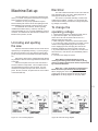
Machine Set-up
The saw delivered to you has been adjusted at the
factory. A number of test pieces have been cut using the
saw to verify the accuracy of cutting.
Therefore, the only set-up operations required
before releasing the saw for service are spotting the saw
and establishing the electrical connections to the motor.
If ordered with the coolant kit, the kit is typically
installed at the Wilton factory. However, if the kit is
ordered separately by you, it must be installed by a set-up
mechanic, so instructions for this task are included in this
Machine set-up section, as well.
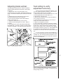
Uncrating and spotting
the saw
Spot the saw where it makes the most sense for the
operations you will probably be doing. If you are going to
be doing cut-off work on very long pieces of stock, allow
plenty of room for the stock, infeed and outfeed supports,
etc.
Remove the saw from the shipping skid and discard
any hold-down devices which might have secured the saw
to the skid.
Note the lock plate on the arm of the saw which is
secured under the bump rubber. This lock plate must be
removed before the saw arm can be raised. You may
discard the lock plate and cap screw used to hold it in
place. Be sure, however, to replace the nut on the bottom
of the horizontal stop.
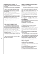
Electrical
The saw is delivered as either a 120 volt or 240 volt
saw, depending upon your order. Wiring diagrams for
either type of circuit are shown here.
The motor is connected, internally, to achieve the
voltage set-up required. However, you can change the
motor's internal wiring connections to change the operating voltage, if necessary.
To change the
operating voltage
1. Disconnect the saw from its electrical power source.
2. Open the motor plate. The requirements for
either 120 or 240 volt connection will be seen on a
diagram inside the motor plate.
3. After making the connections, close the motor plate.
4. If you are using a plug connection to a socket, you will
need to use the appropriate plug for the new power
source supplying the saw, then plug the cord into the
supplying receptacle to reconnect power to the saw.
5. If you are hard wired to a junction box, connect to the
wires in the box, close the box, and reestablish power to
the branch.
6. The saw is now ready for service.
Note: Wilton recommends that any wiring
involving hard wiring of the saw to a branch, or any
change of voltage supplied to the motor, be performed
by a licensed electrician.
Note: also --- if the coolant kit is installed on the
Model 3410 saw is perwired for 120 volt operation .
When changing the motor voltage to 240 volts, the
coolant pump must be changed to 240 volt following
Figure-20 or the wiring diagram on the pump lable.
21
Figure 19: 115 volt wiring diagram
Figure 20: 230 Volt wiring diagram
Installing the coolant kit
1. Install the baffle in the tank so the pump is held at one
end of the tank.
2. Put the tank and pump assembly in the flanges which
hold it in the saw base. The pump should be at the saw
motor end of the base.
3. Install the nozzle assembly in the fixture in the righthand guide bearing bracket and secure it with the set
screw in the fixture.
4. Install the delivery hose between the nipple on the
pump and the nipple on the nozzle assembly.
5. Install the return line between the nipple on the table
and the empty side of the tank.
6. Wire the pump motor to the pump switch according to
the wiring diagram on the facing page. Female spade
clips for the pump-to-switch connections are not supplied
with the kit and must be sourced locally, by you.
7. Test the system by putting coolant in the tank and
turning on the pump switch and motor switch.
8. The system is ready for use on the saw.
Chip brush replacement
The chip brush is a circular wire brush which is
mounted in a bracket at the right-hand side of the saw
arm. The purpose of the brush is to remove chips from
the saw teeth and off of the blade so excessive amounts
of chips don't get into the wheel guard section of the saw.
The brush shaft spins in the bracket and the shaft is
secured using a set screw and collar. With extended use
this brush will be worn and require replacement.
1. Disconnect the saw from its power source to prevent
accidental motor start-up.
2. Remove the set screw and collar from the brush shaft.
3. Remove the old brush and replace it with a new one.
4. Install the collar and set screw so the brush can spin
freely in the bracket.
5. Adjust the bracket, if necessary, so the brush makes
light contact with the saw blade.
22
Adjusting the horizontal stop
and motor switch
The horizontal stop and motor switch are located on
the front of the saw table at the left hand side. The
horizontal stop is a rubber disc, mounted on a flat-headed
screw. The screw height, and therefore the horizontal
position of the saw arm, is adjusted using two nuts on the
screw.
The motor switch is supposed to turn the motor off
just before the arm contacts the horizontal stop. In this
way a complete cut can be made and the blade can be
automatically stopped before the arm is lifted to set up
another cut.
Adjust the horizontal stop whenever the rubber disc
is worn to the point where the stop requires replacement.
To replace or adjust the horizontal stop:
1. Disconnect the saw from its electrical power source to
prevent accidental motor start up.
2. Raise the saw arm to its full up position.
3. Remove the lower nut which secures the horizontal
stop screw to the saw and remove the horizontal stop
assembly, complete.
4. Install the new horizontal stop and make the nuts
which secure it finger tight.
5. Lower the saw arm to its horizontal position.
7. Adjust the horizontal stop height, using the upper and
lower nuts, until the saw blade is below the level of the
table surface and is fully into the blade relief slot on the
table.
8. To be certain the blade has made enough downward
travel to make a complete cut on the largest workpiece
which fits in the saw:
8.1. Open the adjustable vise jaw to its widest position
8.2. Place a straight edge flat on the saw table and
move it to where it contacts the blade.
8.3. The saw blade teeth should be below the saw table
along the entire distance you can slide the straight edge.
Adjust the horizontal stop until this condition is met.
9. Tighten the horizontal stop nuts securely.
10. Reestablish the electrical connection to the saw and
proceed to adjust the motor switch actuator.
Adjusting the
motor switch actuator
1. Raise the arm until the switch actuator is not in contact
with the switch.
2. Turn the switch ON.
3. Lower the arm until the arm contacts the horizontal
stop. The motor switch should shut off the motor just
before the arm contacts the horizontal stop.
4. If necessary, bend the switch actuator and re-test the
system until the correct motor shut-off instant is obtained.
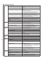
Troubleshooting
Problem
Excessive
blade
breakage
Probable cause
Material loose in the vise
Incorrect feed or speed
Incorrect blade tension
Teeth in contact with work before saw is
started
Blade rubs on wheel flange
Misaligned blade guides
Blade too thick for wheel diameter
Premature
blade
dulling
Cracking at weld
Teeth too coarse
Too much blade speed
Inadequate feed pressure
Hard spot or scale on material
Work hardening of material (especially
stainless steel)
Blade installed backwards
Incorrect coolant or no coolant
Crooked
cuts
Insufficient blade tension
Work not square
Potential solutions
1. Use more pressure to tighten vise.
2. Check stationary jaw pivot and lock bolts for tightness.
3. Check quick release handle nut for excessive tightness
-- nut should be just tight enough to keep adjustable jaw
from tilting when tightening.
4. If you are stacking multiple pieces in the vise, be sure
all of the pieces are captured by the vise pressure.
1. Check technical literature for recommended feeds and
speeds for the material and blade you are using.
2. Check chip formation to adjust speed and feed to
correct rate when sawing.
1. Adjust blade tension to where it just does not slip on
the wheel.
1. Be sure the saw motor has come fully up to speed
before beginning a cut and be sure the blade is not resting
on the workpiece before the motor has come up to full
speed.
1. Use paper cutting method of adjusting blade tracking.
See Blade Tracking Adjustment.
2. Check drive and idler wheels for looseness in mounting parts or worn/damaged bearings.
1. Adjust blade guides.
1. Use a thinner blade. Check with your blade supplier
for recommendations on blade thickness for a specific
wheel diameter.
1. Replace blade.
1. Use finer tooth blade.
1. Try next lower speed or check technical literature for
specific recommendations regarding speeds for specific
blade and material being cut.
2. Check with materials supplier for recommendations on
the workpiece material supplied.
3. If using coolant, check with supplier regarding correct
coolant for the job.
1. Increase pressure while observing chip formation to be
sure you are cutting efficiently.
1. Reduce speed of blade.
2. Increase feed pressure in scale or hard spots .
1. Work hardening materials such as stainless require a
heavy, continuous cut. Be sure you are using a sharp
blade, then, if necessary, release some counterbalance
spring pressure by loosening the tension nut if work
hardening of the material is a problem.
1. Reinstall blade so teeth point toward right end of saw.
1. Check with materials supplier and/or blade supplier for
coolant recommendations.
2. Check with coolant supplier for specific recommendations on the blade and material you are using.
1. Increase tension so blade is above the slipping point.
1. Adjust the stationary vise jaw so it is square to the
blade.
2. Clamp work tightly in the vise.
3. Check blade for vertical and adjust, if necessary.
4. Perform test cuts according to instructions on page
until cuts are satisfactorily square.
5. Move guide bearings as close as possible to work
while still completing the cut.
6. Check guide bearings, seats and brackets for possible
looseness or wear.
23
Troubleshooting
Feed pressure too great
Guide bearings not adjusted properly
Inadequate blade tension
Blade guides incorrectly spaced
Dull blade
Incorrect speed
Rough
cuts
Blade guide assembly loose
Blade guide bearing assembly loose
Blade tracking too far away from wheel
flanges
Worn upper wheel bearings
Loose upper wheel mounting assembly
Too much feed or speed
Blade too coarse
Incorrect blade for material
Blade
twisting
Cut is binding blade
Too much blade tension
Loose guide bearing eccentrics
Worn guide bearings
Incorrect guide bearing adjustment
Loose guide bearing bracket
Loose bearing seat attachment screw
24
Unusual
wear on
side/back of
blade
Breaking
teeth
Blade guides worn
Blade guide bearings not adjusted properly
Blade guide bearing bracket loose
Blade running on wheel flange
Teeth too coarse for work
Too heavy feed
Too slow speed
Vibrating work piece
Tooth gullets loading
Motor
running too
hot
Blade in contact with workpiece before motor
is started
Blade tension too high
Blade too coarse for work (pipes, especially)
Blade is too fine for work (heavier, soft
material)
Worn transmission and worm gear
Gears need lubrication
1. Observe chip formation to be sure cutting is efficient.
1. Adjust guide bearings according to instruction in this
manual.
1. Increase blade tension so blade does not slip on the
wheels.
1. Move guide brackets until they just clear the workpiece
while making a complete cut.
2. For small section pieces, be sure the blade is sharp
and correctly tensioned. Use less feed pressure.
1. Replace blade when it dulls.
2. Consider using a coolant, if not already used.
1. Check technical literature for recommended speeds
and blade type for material being cut -- observe chip
formation to verify efficient cutting.
1. Tighten guide bracket.
1. Check tightness of bearing seat bolt.
1. Use paper cutting method of setting blade tracking.
1. Replace bearings if worn.
1. Tighten all bolts securing wheel to arm.
1. Try one step lower speed and observe chip formation
for efficient cutting/feed rate.
1. Use finer blade. Check with suppliers for recommendations for the material you are cutting.
1. Check with blade suppliers for recommendations for
exotic or unusual materials or specifications.
1. Be sure workpiece is flat on saw table.
2. Decrease feed pressure.
1. Reduce tension to just above point where blade slips.
1. Check eccentric jam nuts for tightness.
1. Check guide bearings for wear. Replace if necessary.
1. Adjust guide bearings according to instructions in this
manual.
1. Tighten bracket on saw arm.
1. Tighten bearing seat attachment screw -- adjust blade
for vertical and parallel.
1. Replace.
1. Check and adjust for proper clearance.
1. Tighten bracket to saw arm.
1. Adjust blade tracking using the paper cutting method.
1. Use blade with finer pitch.
1. Decrease feed rate -- observe chip formation to verify
efficient cutting.
1. Increase blade speed. Check technical literature or
blade or workpiece supplier for blade speed recommendations.
1. Be sure vise is tight.
2. Support slender cross section or long workpieces with
appropriate out-feed supports.
3. If stacking pieces in the vise, be sure all workpieces
are securely captured by the vise.
1. Use coarser blade or one with a tooth geometry more
appropriate to the workpiece being cut.
1. Always allow motor to come fully up to speed before
beginning cut.
1. Decrease blade tension to just above slip point.
1. Use finer pitch blade.
1. Use coarser blade.
1. Replace gears in transmission gearbox.
1. Check gearbox and add oil as required.
Replacement Parts
This section provides exploded view illustrations that show the replacement parts for the Model 3400 and 3410
7-Inch x 12-Inch Horizontal Cut-Off Band Saw. Also provided are parts listings that provide part number and
description. The item numbers shown on the illustration relate to the item number in the facing parts listing.
Order replacement parts from:
WHM TOOL GROUP
2420 Vantage Drive
Elgin, Illinois 60124
Ph.: 800-274-6848
Identify the replacement part by the part number shown in the parts listing. Be sure to include the model
number and serial number of your machine when ordering replacement parts to assure that you will receive
the correct part.
25
26
Exploded View - Saw Head
Parts List - Saw Head
Ref.
no.
1
2
4-1
5
6
7
8
9A
10A
11A
12
12
13
14
Part.no.
5710011
5710021
5710041
5710051
5710061
5710071
5710081
5710091
5710111
5710121
5710131
5711921
5710141
Description
Pulley cover
Motor pulley
HH screw 5/16X1
Motor 3/4 HP 115V 1PH
Motor mount plate assy.
HH screw 5/16x5/8
HH screw 5/16x1-1/4
Tapping screw 6mmx20
Gearbox cover
Gearbox gasket
Trnsmsion gear 20mm bore
Trnsmsion gear 25mm bore
Ball bearing 6005
Saw Blade:
5632141 3/4 X .032 X 93" 8 TPI
5632151 3/4 X .032 X 93" 8 T STND
5632161 3/4 X .032 X 93" 14 TPI
15
5710161 Oil seal 20.42.7
5711881 Oil seal 25.47.7
16
5635271 Ball bearing 6004Z
5680391 Ball bearing 6005Z
17
5710181 Trnsmsion Shaft - 5/8 bore
5711931 Trnsmsion Shaft - 7/8 bore
18
5710191 Blade whl rear 20mm bore
5711831 Blade whl rear 25mm bore
19
5710211 Washer 3/8
21
5710231 Belt 3V-270
22
5710241 Worm pulley
23
5710251 Set screw 5/16x3/8
23-1 5517501 Set screw 5/16x3/4
25
9100451 Ball bearing 6003
26
5710281 Oil seal 17.35.7
27
5710291 Bearing bushing
28
5710311 Ball bearing 6003
29
5710321 Worm gear shaft
30
5710331 Snap ring 42mm
30
5711871 Snap ring 47mm
31
9052181 HH screw 5/16x1-1/2
32
5710351 Blade tension sliding plate
33
5710361 Sliding plate draw block
34
5710371 Blade wheel shaft - front
35
5710381 Bearing bushing
36
9100331 Ball bearing 6203
37
5710411 Switch actuator
38
5710421 Blade wheel - front
39
9100331 Ball bearing 6203
40
5710441 Phillips screw 1/4x1/2
41
5710451 HH screw 5/16x3/4
42
5710461 HH screw 1/4x1/2
42-1 5517502 Spring washer 1/4
42-2 5517503 Washer 1/4
43
5710471 Blade tension sliding guides
44
5710481 Blade tension adj. knob
45
5630601 Knob
46A 5710511 Transmission gearbox 42mm
5711861 Transmission gearbox 47mm
47
5710521 Adjustable bracket bar - front
48
5710531 Blade adjustable seat - front
49
5632831 Ball bearing 608ZZ
Qty.
1
1
4
1
1
3
1
4
1
1
1
2
1
1
1
1
1
1
1
1
3
1
1
1
1
2
1
2
2
1
1
1
1
1
1
1
1
4
1
7
1
1
2
1
2
1
1
1
2
Ref.
Part.no.
no.
50
51
51-1
52
53
54A
55
56
57
58
59
60
61
62
62-1
62-2
63
65
5710551
5710561
5517504
5710571
5710581
5710591
5710611
5710621
5710631
5710641
5710651
5710661
5710671
5710681
5517505
5517506
5710691
5710721
5711821
66
5710731
67
5710741
67A 5711561
68
5710751
5711811
85
5710941
87
5710961
93
5711031
93-1 5517507
94
5711041
98
5711081
103 5711141
116 5711281
122 5711351
141 5711561
142 5711571
145 5711391
147 5711431
148 5711471
149 5711481
150 5711841
152 5710531A
153 5710631A
155 5711951
156 5711251
158 5711991
159 5710511A
160 5711801
161 5517509
162 5517510
163 5517511
164 5517512
165 5517513
166 5517514
167 5517515
168 5517516
169 5517517
170 5517518
171 5517519
172 5517508
5711421
Description
Bearing pin
Eccentric shaft assy.
Center shaft assy.
Brush
Hex nut 3/8x24
Oil plug
Phillips screw 1/4x3/8
Vertical cutting plate
Blade adjustable sear - rear
Adjustable bracket bar - rear
SHCS 5/16x1-1/8
Vertical cutting plate (small)
Brush bracket
Nozzle bracket
Valve
Nozzle cock
Blade guard
Saw bow (arm)-rounded style
Saw bow (arm)-square style
HH screw 5/16x2-1/2
Thumb screw
Washer 1/4
Blade cover assy early style
Blade cover assy later style
Washer 5/16
Collar
Spring washer 5/16
Adj. Screw 1/4x3/8
Nut 5/16
Set screw 1/4x1/4
Washer 5/16
Hex nut 5/16
Key 5mm
Washer 1/4
Screw 3/16x1/4
Cooling fan cover
Capacitor cover
Capacitor
Cooling fan
Bushing
Blade guide assy left side
Blade guide assy right side
Rubber flap
Cord
C-clip
Cmplte gearbox 42mm bore
Cmplte gearbox 47mm bore
Block plate
Hex soc. screw 3/16x1/2
Bearing bushing
Key 6x20
HH screw 3/8x1
Spring washer 3/8
Washer 3/8x35x4
Top support
HH screw 3/8x1-1/2
Spring washer 3/8
Nut 3/8
HH screw 1/4x3/8
Junction box cvr (not shown)
Qty.
2
2
2
1
4
1
2
1
1
1
2
1
1
1
1
1
1
1
2
3
2
1
6
1
13
2
4
2
2
1
1
8
2
1
1
1
1
1
1
1
1
1
1
1
1
1
3
1
1
1
1
1
1
2
2
2
2
1
27
Exploded View - Saw Base
28
Parts List - Saw Base
Ref. Part no. Description
no.
19
20
20-1
68
69
70
71
72
73
74
75
76
77
77-1
78
79
81
5710211
5710221
5517520
5517521
5710761
5710771
5710781
5710791
5710811
5710821
5710831
5710841
5710851
5517522
5628371
5507523
5710891
5711781
82
5710911
83
5710921
83
5711791
84
5710931
85
5710941
86
5710951
88
5517523
88-1 5517524
89
5710981
90
5710991
91
5711011
92
5711411
93
5711031
94
5711041
95
5711051
5711751
96
5517525
97
5517526
99A 5517527
100 5711111
101 5711061
102 5711131
104 5711151
105 5711161
107 5711181
5711761
108 5711191
Spring washer 3/8
HH screw 5/16x3/4
HH screw 5/16x1/2
Set screw 5/16x3/8
Handle
Nut
Vise screw
Spring
Vise thrust shaft
Nut seat
Vice jaw movable
Vice jaw stationary
HH screw 1/2x1-1/2
HH screw 1/2x1-1/4
Spring washer 1/2
Washer 1/2
Handle wheel 13mm
Handle wheel 15mm
Set screw 5/16x3/8
Lead screw - 13mm
Lead screw - 15mm
HH screw 5/16x1
Washer 5/16
Lead screw seat
RH Ph. Screw 3/16x1/4
RH Ph. Screw 3/16x3/8
Spring handle mount - rear
Spring adjustable rod
Spring
HH screw 5/16x1-1/4
Spring washer 5/16
Nut 5/16
Pivot arm - 5/8 bore
Pivot arm - 7/8 bore
HH screw 3/8x1 3/4
Nut 3/8
Fiber hex. nut 1/2
Washer 1/2
HH screw 3/8x1-1/2
Spring Washer 3/8
Power switch Assembly
Angle scale
Table - 5/8 bore
Table - 7/8 bore
HH screw 3/8x1
Qty.
2
8
6
1
1
1
1
1
1
1
1
1
1
1
2
1
1
1
1
2
37
1
2
2
1
1
1
1
23
21
1
1
3
2
2
2
2
2
1
1
2
Ref. Part no. Description
no.
109
110
111
115
119
120
121
123
124
125
127
130
131
131A
132
135A
137
138
139
143
144
161
146
147
148
149
150
151
152
153
154
155
156
157
160
160A
162
163
164
165
166
167
168
169
170
171
172
9056991 Nut 3/8x7x14
5711221 90 degree support
5517529 HH screw 3/8x1-3/4
5711271 Support shaft -5/8
5711771 Support shaft - 7/8
5711321 Stock stop
5711331 Thumb screw
5711341 Stock stop rod
5517530 HH screw 5/16x3/4
5711371 Horizontal stop screw support
5711381 Horizontal stop screw
5517531 HH screw 5/16x1
5711441 Trough
5711451 Floor stand, left
5711451R Floor stand, right
5711461 Skirt
5711491 Shelf
5711521 Enclosure
5711531 Gasket
5711541 Cover plate
5711261 Screen
5711961 Spacer
5711941 Drain hose
5711971 Switch box
5711981 Round head screw 3/16x3/8
5517535 Cylinder
5517536 Hex. soc. screw M10x40
5517537 Washer 3/8
5517538 Spring washer 3/8
5517539 Nut M10
5517540 HH screw 3/8x1
5517541 Spring washer 3/8
5517542 Set screw
5517543 Bottom support
5517544 Support rod
5042291 Modular box
5711452 Plastic funnel
5042281 Coolant pump 120V/240V
5517532 HH. screw 1/4x1/2
5517533 Hose fitting
5517534 Hose Clamp 13mm
9307291 Hose
5517528 Jam nut 3/8
5635500 Wet kit
5518228 Flat Washer 5/8
5518229 Wheel
5518230 Wheel shaft
5518231 Split pin
Qty.
2
1
2
1
1
1
1
2
1
1
5
1
1
1
1
1
1
1
1
1
1
1
1
2
1
1
1
1
1
2
2
1
1
1
1
1
1
4
1
1
1
1
2
4
4
2
4
29
Parts List - Hydraulic Cylinder
30
Ref. Part no. Description
no.
1
2
3
4
5
6
7
8
5517547
5517548
5517549
5517550
5517551
5517552
5517553
5517554
Dust cover
Retaining ring
Oil-seal
Oil-piston
O-ring
Cylinder body
Oil pressure regulator
Oil duct
Qty.
1
2
1
1
1
1
1
1