1
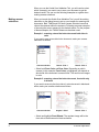
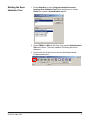
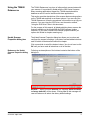
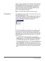
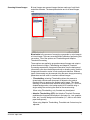
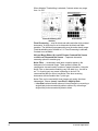
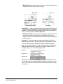
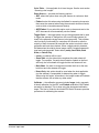
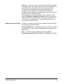
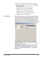
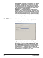
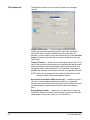
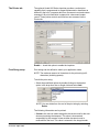
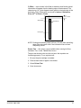
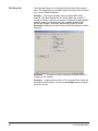
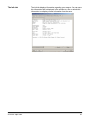
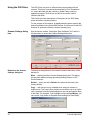
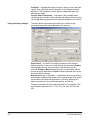
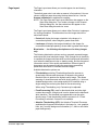
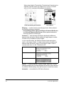
i200 Series Scanners Image Processing Guide A-61520 Image Processing Guide for i200 Series Scanners Overview This documentation introduces concepts that may be new to many users. The Kodak i200 Series Scanners provide the ability to process scanned images to improve their quality. Using these features the scanner can sometimes make the scanned image look better than the original document. Basic image processing concepts are reviewed in this chapter to help you take advantage of these powerful features. Image processing refers to several separate features of the scanner that allow you to automatically adjust each image in a certain way that may improve the resulting images. Common examples of image processing features are correcting any skew in the fed document, cutting the edges of the image off to remove any unneeded border or cleaning up extraneous “noise” on the image. The idea is to do this automatically so you can get better images with a minimum amount of rework. The information that follows describes the image processing features by walking you through the Scan Validation Tool. The same options should be available on the user interface of the software application you are using (i.e., Kodak Capture Software). All fields on the Scan Validation Tool are described in this document. Common terms Following are a few common terms that are used throughout this document: Bi-tonal or Binary — black-and-white. Simplex — indicates that only one side of the document (the front side) will be scanned, creating a single page image. Duplex — indicates that both sides of the document will be scanned, creating two page images. Cameras — it is important to understand the concept of “cameras”. The Kodak i250 Scanner is a simplex scanner. The camera has the ability to separate color and bi-tonal/binary data simultaneously. This means it scans one-sided documents; a front color image and a front bitonal/binary image, allowing you to capture one side of a document either in color/grayscale or black-and-white. Effectively the means you have two cameras on the i250 Scanner; front color and front bi-tonal. The Kodak i260 and i280 Scanner are a duplex scanners. The cameras have the ability to separate color and bi-tonal/binary data simultaneously. This means it scans both sides of a two-sided document; a front color image, a rear color image, a front bi-tonal/ binary image, and a rear bi-tonal/binary image, allowing you to capture both sides of a document in either color/grayscale, black-and-white, or a combination of color and black-and-white. Effectively this means that you have four cameras on the i260 and i280 Scanners; front color, rear color, front bi-tonal and rear bi-tonal. A-61520 April 2005 1 When you use the Kodak Scan Validation Tool, you will need to select which camera(s) you want to use to scan your document to get the desired results. You can use the following examples as a guide when making camera selections. Making camera selections When you launch the Kodak Scan Validation Tool, you will be making selections on the dialog boxes to set up your images for scanning test documents. Both TWAIN and ISIS have camera selection boxes that refer to the cameras within the scanners. Following are some examples of choosing the correct camera for the desired results. For the purpose of these examples, the TWAIN Datasource has been used. Example 1: scanning a two-sided color document both sides in color If you want to scan a two-sided color document, make your camera selections as follows: Camera selection Result - Side 1 Result - Side 2 • Select both Front Color and Rear Color. Depending on which camera (in this example, Front Color) is highlighted, will depend on which side of the document is scanned first. The result is two images in color. Example 2: scanning a two-sided color document, front side only in bi-tonal If you want to scan only the front side of a color document in black-andwhite, make your camera selections as follows: Camera selection Original - Side 1 Result - Side 1 • Select and highlight Front Bitonal. The resultant image will be the front side of the document in black-and-white. 2 A-61520 April 2005 Starting the Scan Validation Tool 1. Select Start>Run or select Programs>Kodak>Document Imaging>Scan Validation Tool. Enter the filename or choose Browse to locate the ScanValidation.exe file. 2. Select TWAIN (or ISIS) for the Driver Type and the Kodak Scanner i200 as the Driver. The Scan Validation Tool dialog box will be displayed. 3. Double-click the Scanner icon to access the Kodak Scanner Properties dialog box. A-61520 April 2005 3 Scan Validation Tool dialog box The Scan Validation Tool (SVT) is a diagnostic application that Kodak provides with most Kodak scanners. The SVT user interface allows access to all the features of the scanner and is a good way to verify that the scanner is working properly. The Scan Validation Tool allows you to verify scanner functionality using both the TWAIN Datasource and the ISIS Driver. Displays the user interface for the selected driver. Disables the scanner Displays four images at a time Enables the scanner Closes the image viewer (no images will be displayed) Enables to scanner to feed one page Allows you to select the directory to store scanned images and their file names. Only available when Save Images to Files is selected. Displays eight images at a time Displays two images at a time Displays one image at a time Displays the License Key window Display Every enter the sampling rate of the images you wish to display while scanning. For example, to see every image, enter a value of 1. To see every 10th image, enter a value of 10. Last File displays the full path and file name for the last stored image. Total displays the total number of images scanned during the current Scan Validation Tool session. 4 A-61520 April 2005 Using the TWAIN Datasource The TWAIN Datasource is a piece of software that communicates with your scanner. It is provided by Kodak with the i200 Series Scanners. Many scanning applications support the TWAIN standard and this datasource can be used to interface with these applications. This section provides descriptions of the scanner features using options on the TWAIN tabs and how to set these options. If you are using the TWAIN Datasource, follow the procedures in this section to set up your scanner. If you are using the ISIS Driver, see the section entitled, “Using the ISIS Driver” later in this document. For the purpose of this manual, all displayed dialog boxes assume the features available on the Kodak i260 and i280 Scanners (duplex scanners). If you have a Kodak i250 Scanner (simplex scanner) all options are limited to simplex scanning only. Kodak Scanner Properties dialog box The Kodak Scanner Properties dialog box allows you to review and configure the scanner’s settings. It consists of several tabbed windows each of which will be described within this chapter. Click on each tab to set all the desired values. You do not have to click OK until you have made all selections on all of the tabs. Buttons on the Kodak Scanner Properties dialog box Following are descriptions of the buttons located at the bottom of the dialog box. Defaults when you select Defaults, the message Reset all values to factory defaults? will be shown. Clicking Yes on this message will reset all values on all tabs to the factory default settings. A-61520 April 2005 5 Copy copies the settings of the front camera to the rear camera for the selected camera (bi-tonal, color or grayscale). For example, if you have Front Bi-tonal highlighted, these values will be copied to the Rear Bi-tonal camera. If you have Front Color highlighted, these values will be copied to the Rear Color camera. This option is only available for the Kodak i260 and i280 Scanners. OK saves the values set on all tabs. Cancel closes the dialog box without saving any changes. The Imaging tab The Imaging tab allows you to define several image processing values that can be applied to your scanner. The Camera Selection box lists the available sides (front and rear) of any document where you can define individual image processing values. For detailed information about the cameras, refer to the beginning of this chapter, “Making camera selections”. On the Kodak i250/i280 Scanner (duplex) there is a separate camera for each side of the document being scanned. The Kodak Scanner Drivers allow you to control the camera settings independently. Some settings apply only to bi-tonal images, other apply to color images. By selecting the appropriate camera and image type you can control the scanner’s output. • If you have a Kodak i260 or i280 Scanner, you can select any individual camera (i.e., Front Color, Rear Color, Front Bi-tonal and/ or Rear Bi-tonal) or any combination of the cameras. This means you can do the front side, rear side or both sides of a document. • If you have a Kodak i250 Scanner, you can select either Front Color and/or Front Bi-tonal. This means you can do the front side of a document depending on how the documents are placed in the feeder. • Whatever is highlighted in the Camera Selection box determines the values available on the Imaging, Paper, Compression and Dropout tabs. 6 A-61520 April 2005 Scanning bi-tonal images Bi-tonal images are scanned images that are made up of only blackand-white elements. The descriptions below are for bi-tonal images only. Binarization is the process of converting a grayscale or color image to a bi-tonal image. There are several different methods of performing this conversion. Two of the options are iThresholding and Adaptive Threshold Processing. These options are applied to grayscale scanned images and output a bi-tonal electronic image. iThresholding and Adaptive Threshold Processing separate the foreground information from the background information even when the background color or shading varies, and the foreground information varies in color quality and darkness. Different types of documents may be scanned using the same image processing parameters and still result in excellent scanned images. • iThresholding: selecting iThresholding allows the scanner to dynamically evaluate each document to determine the optimal threshold value to produce the highest quality image. This allows scanning of mixed document sets with varying quality (i.e., faint text, shaded backgrounds, color backgrounds) to be scanned using a single setting thus reducing the need for document sorting. When using iThresholding, only Contrast may be adjusted. • Adaptive Thresholding (ATP): the Adaptive Threshold Processor separates the foreground information in an image (i.e., text, graphics, lines, etc.) from the background information (i.e., white or non-white paper background). When using Adaptive Thresholding, Threshold and Contrast may be adjusted. A-61520 April 2005 7 When Adaptive Thresholding is selected, Contrast values may range from 1 to 100. Fixed thresholding ATP disabled ATP enabled Fixed Processing used for black-and-white and other high contrast documents. A single level is set to determine the black-and-white transition. The threshold is programmable over the entire density range. Fixed thresholding sets Contrast to 0. If Fixed Processing is selected, Contrast is not available. 64-Level Bayer Dither, 64-Level 45 Degree Clustered Dot Screen and 64-Level Dispersed Dot Screen represent alternative screening options to emulate gray. Noise Filter occasionally small dots or specks appear in the background of a scanned image. These specks increase file compression size and usually contain no image information. Using the Noise Filter on documents containing very fine detail (e.g., the dot on an "i" in 4-point type) may cause information to be lost. It is recommended that you do not use Noise Filter when scanning documents with text smaller than 7-point type. Noise Filter can be used with bi-tonal images only and is front/rear independent. Choose (none), Lone Pixel or Majority Rule. • Lone Pixel reduces random noise on bi-tonal images by converting a single black pixel surrounded by white to white or by converting a single white pixel surrounded by black to black. 8 A-61520 April 2005 • Majority Rule sets the central pixel value in a matrix according to the majority of white or black pixels in a matrix. No Noise Filter Used Lone Pixel Image Filter used to enhance images containing dot matrix text and/ or images printed with shaded or colored backgrounds using halftone screens. This filter effectively eliminates noise caused by the halftone screen. Choose (none) or Halftone Removal. • Halftone Removal is used to enhance images containing dot matrix text and/or images with shaded or colored backgrounds using halftone screens. This filter effectively eliminates noise caused by the halftone screen. Contrast % sets the image contrast by adjusting the difference between black-and-white, thereby making an image sharper or softer. In a low contrast setting, the difference between black-and-white is small, so the image is softer. In a high contrast setting, the difference between black-and-white is large, so the image is clearer. Select a contrast value from 1 to 100. The default is 50. Contrast 1 Contrast 60 Contrast 100 Adjust the contrast setting by dragging the Contrast sliding bar to the left or right to achieve the desired contrast setting, or you can enter a value (1 to 100) in the Contrast text box. Scan the document to check the contrast. A-61520 April 2005 9 Threshold used to convert a grayscale image to a bi-tonal image. The thresholding value is an integer ranging from 0 to 255. A low threshold value produces a lighter image, and can be used to subdue backgrounds and subtle, unneeded information. A high threshold value produces a darker image, and can be used to help pick up faint images. Adjust the threshold setting by dragging the Threshold sliding bar to the left or right to achieve the desired threshold setting, or you can enter a value (0 to 255) in the Threshold text box. Scan the document to check the threshold. 200 dpi; 80 Threshold 20 Contrast 200 dpi; 80 Threshold 100 Contrast Resolution or dots per inch (dpi) indicates the scanning resolution, which largely determines the quality of the scanned image. The greater the resolution, the better the reproduction. However, scanning at a higher resolution also increases scanning time and file size. The industry standard is 200 dpi (about 8 pixels/mm). Choose a resolution value from the drop down list. The default value is 200 dpi. Available resolutions are 75, 100, 150, 200, 240, 300, 400 or 600. Polarity the host PC provides information to the scanner defining whether the image should be stored in standard or reverse polarity. The default polarity is Black on a White background. Reverse polarity is White on a Black background. Black on White polarity 10 White on Black polarity A-61520 April 2005 Color Table Not applicable for bi-tonal images. See the next section “Scanning color images”. Paper Source — provides the following options: • ADF: select this option when using the scanner in continuous feed mode. • Flatbed: select this when using the flatbed for scanning documents that cannot be scanned when using the automatic document feeder, such as thick or bound documents (books). • ADF/Flatbed: if you select this option, and no documents are in the ADF, the scanner will automatically use the flatbed. Toggle Patch — the toggle patch is a type 4/toggle patch that is used to trigger the scanner to change from the current image stream (bitonal) to the alternative image stream (color/grayscale). This provides color-on-the-fly functionality for customers who choose to scan the majority of their documents bi-tonal with the option to switch to color/ grayscale and back when desired. When a toggle patch is detected, this determines the side(s) whose image output is toggled between bitonal and color/grayscale. Select either (none), Same Side, Both Sides, or Detect Only. • (none): no patches will be used. • Same Side: only the side which recognizes the patch sheet will toggle. For example, if a patch sheet contains a patch on the front side only, the front stream will toggle but the rear stream will not. • Both Sides: if a patch is recognized on either the front or the rear, both front and rear streams will toggle. • Detect Only: this option should be used when the host application (not the scanner) is responsible for determining when to toggle. When using this option, information in the image header will indicate that the scanner will not take any other action. Calibrate — the calibration process includes Image (color, grayscale, bi-tonal) calibration for the ADF, and Flatbed calibration if the Flatbed accessory is attached. This is done using the designated calibration target. The User’s Guide for the Kodak i200 Series Scanners provides procedures for calibrating the scanner. A-61520 April 2005 11 Scanning color images The descriptions below are for scanning color images only. Resolution or dots per inch (dpi) indicates the scanning resolution, which largely determines the quality of the scanned image. The greater the resolution, the better the reproduction. However, scanning at a higher resolution also increases scanning time and file size. Choose a resolution value from the drop down list. The default is 200 dpi. Available resolutions are: 75, 100, 150, 200, 240, 300, 400 or 600. Color Table the selection of a color table effects how the scanner reproduces the color of a scanned document. Color Tables are look-up tables that store color descriptions which can be used for gamma correction of images being transferred between different equipment (i.e., scanners, printers, monitors, etc.). You can choose from these Kodak default color tables: Mixed, Mixed 1, Mixed 2, Mixed 3, Photo and Text, or if you have created your own custom color tables using the Brightness and Contrast Control, these tables will also be available. For more information on the Brightness and Contrast Control, see the Reference Guide, A-61506. Convert Color to Grayscale enable this option when you want the captured image to be 8-bit grayscale instead of 24-bit color. Paper Source — provides the following options: • ADF: select this option when using the scanner in continuous feed mode. • Flatbed: select this when using the flatbed for scanning documents that cannot be scanned when using the automatic document feeder, such as thick or bound documents (books). • ADF/Flatbed: if you select this option, and no documents are in the ADF, the scanner will automatically use the flatbed. 12 A-61520 April 2005 Toggle Patch — the toggle patch is a type 4/toggle patch that is used to trigger the scanner to change from the current image stream (bitonal) to the alternative image stream (color/grayscale). This provides color-on-the-fly functionality for customers who choose to scan the majority of their documents bi-tonal with the option to switch to color/ grayscale and back when desired. When a toggle patch is detected, this determines the side(s) whose image output is toggled between bitonal and color/grayscale. Select either (none), Same Side, Both Sides, or Detect Only. • (none): no patches will be used. • Same Side: only the side which recognizes the patch sheet will toggle. For example, if a patch sheet contains a patch on the front side only, the front stream will toggle but the rear stream will not. • Both Sides: if a patch is recognized on either the front or the rear, both front and rear streams will toggle. • Detect Only: this option should be used when the host application (not the scanner) is responsible for determining when to toggle. When using this option, information in the image header will indicate that the scanner will not take any other action. Calibrate — the calibration process includes Image (color, grayscale, bi-tonal) calibration for the ADF, and Flatbed calibration if the Flatbed accessory is attached. This is done using the designated calibration target. The User’s Guide for the Kodak i200 Series Scanners provides procedures for calibrating the scanner. A-61520 April 2005 13 Scanning grayscale images The descriptions below are for scanning grayscale images only. Resolution or dots per inch (dpi) indicates the scanning resolution, which largely determines the quality of the scanned image. The greater the resolution, the better the reproduction. However, scanning at a higher resolution also increases scanning time and file size. Choose a resolution value from the drop down list. The default is 200 dpi. Available resolutions are: 75, 100, 150, 200, 240, 300, 400 or 600. Color Tables the selection of a color table effects how the scanner reproduces the color of a scanned document. Color Tables are look-up tables that store color descriptions which can be used for gamma correction of images being transferred between different equipment (i.e., scanners, printers, monitors, etc.). The selection of a color table effects how the scanner reproduces the color of a scanned document. You can choose from these Kodak default color tables: Mixed, Mixed 1, Mixed 2, Mixed 3, Photo and Text, or if you have created your own custom color tables using the Brightness and Contrast Control, these tables will also be available. For more information on the Brightness and Contrast Control, see the Reference Guide, A-61506. Convert Color to Grayscale enable this option when you want the captured image to be 8-bit grayscale instead of 24-bit color. This option must be enabled to get a grayscale image. Paper Source — provides the following options: • ADF: select this option when using the scanner in continuous feed mode. • Flatbed: select this when using the flatbed for scanning documents that cannot be scanned when using the automatic document feeder, such as thick or bound documents (books). • ADF/Flatbed: if you select this option, and no documents are in the ADF, the scanner will automatically use the flatbed. 14 A-61520 April 2005 Toggle Patch — the toggle patch is a type 4/toggle patch that is used to trigger the scanner to change from the current image stream (bitonal) to the alternative image stream (color/grayscale). This provides color-on-the-fly functionality for customers who choose to scan the majority of their documents bi-tonal with the option to switch to color/ grayscale and back when desired. When a toggle patch is detected, this determines the side(s) whose image output is toggled between bitonal and color/grayscale. Select either (none), Same Side, Both Sides, or Detect Only. • (none): no patches will be used. • Same Side: only the side which recognizes the patch sheet will toggle. For example, if a patch sheet contains a patch on the front side only, the front stream will toggle but the rear stream will not. • Both Sides: if a patch is recognized on either the front or the rear, both front and rear streams will toggle. • Detect Only: this option should be used when the host application (not the scanner) is responsible for determining when to toggle. When using this option, information in the image header will indicate that the scanner will not take any other action. Calibrate — the calibration process includes Image (color, grayscale, bi-tonal) calibration for the ADF and Flatbed calibration if the Flatbed accessory is attached. This is done using the designated calibration target. The User’s Guide for the Kodak i200 Series Scanners provides procedures for calibrating the scanner. A-61520 April 2005 15 The Paper tab The Paper tab allows you to define values relating to image output (i.e., cropping values, rotation, paper size and units of measure). Camera selection box lists the available sides of an image that you can define individual image processing values. The display window on the right will display the cropping area you are altering. The cropping area will change as values are being altered. Cropping values Cropping allows you to capture a portion of the document being scanned. Cropping options can be used independently with color/ grayscale and bi-tonal images and are also front and rear side independent, however for simultaneous output scanning color/ grayscale and bi-tonal image cropping must be the same per side. • On an i260 or i280 Scanner two cropping options can be set per document. • On an i250 Scanner one cropping option can be assigned per document. Cropping select one of the following options: • Automatic: dynamically adjusts the cropping window for different document sizes based upon the edges of the image. Use this option for batches of mixed-sized documents. • Aggressive: eliminates any residual white/gray border on any image edges. When using Aggressive cropping, there is a possibility that a small amount of image data from the edge of the document may be lost. • Fixed to Transport: (used for batches of same-sized documents) allows you to define the area or zone to be imaged. If you select this option, enter the x and y offset values, width and length. You can enter the desired values in the fields or use the arrow keys to define the desired area. The Display window will show image placement as you change the values. 16 A-61520 April 2005 • Relative to Document: (zone processing): (used for batches of same-sized documents) — zone processing is a floating fixed crop window located relative to the upper left corner of a document. It allows you to select an area on the document to be delivered in either color/grayscale or bi-tonal format (a separate window for both bi-tonal and color/grayscale may be defined). Different parameters may be selected for both the front and rear of the image. For example, some applications have a requirement to store part of an image in color and the rest of the image in bi-tonal format (this saves storage space by not storing the entire image in color). This option may be used in conjunction with auto cropping where a separate color/grayscale or bi-tonal area to be saved is desired. It is useful in applications where a photograph, signature, embossment or seal appears in a consistent area for an application (you may want that small area in color/grayscale and the rest in bi-tonal). Enter the x and y offset which defines the upper left corner of the zone relative to the upper left corner of the desired document. Enter the length and width of the zone to be captured. Original Bi-tonal image Relative to Document You can enter the desired values in the fields or use the arrow keys to define the desired area. The Display window will show the cropping area as you change the values. Make sure the relative cropping offset, width, and length are correct and that the document is being scanned is at least the same size as the zone you defined. A-61520 April 2005 17 • Long Paper (i280 Scanner only): allows you to scan documents that exceed the 34-inch maximum length. You can scan documents that are up to 609 cm (20 feet) long at resolutions up to 300 dpi. These document types include document rolls (e.g., EKG charts, chart recorder rolls, and other roll-type documents). The scanned document is delivered in multiple image segments. Segment size is defined by entering the x and y offset values, width and length. You can enter the desired values in the fields or use the arrow keys to define the desired area. The Display window shows image placement as you change the values. Recommended segment size is 10 to 12 inches. NOTE: When using the Long Paper option, all selected cameras are affected. Automatic Deskew select this option to automatically deskew a document within ±0.3 degrees of the leading edge of the document. This option is only available if you have Automatic cropping selected. NOTE: To prevent data loss, the document must have all four corners within the image path. X-Offset — for Fixed to Transport cropping, this is the distance from the left end of the scanner to the left edge of the scanning area. For Relative to Document cropping this is the distance from the left edge of the document to the left edge of the zone. This option is not available if you use Automatic or Aggressive cropping. Y-Offset — for Fixed to Transport and Relative to Document cropping, this is the position from the top end of the document to the top end of the scanning area. This option is not available if you use Automatic, Aggressive or Long Paper cropping. Width — the width of the scanning area. This option is not available if you use Automatic or Aggressive cropping. Length — the length of the scanning area. If Overscan is not selected, the scanner will not continue capturing beyond the trail edge of the document. For example, if you setup the scanner for 8 1/2 x 11”, portrait-fed documents, and you scan an 8 1/2 x 4” document, the scanner will return an 8 1/2 x 4” scanned area. This option is not available if you use Automatic or Aggressive cropping. Center Frame — when using Fixed to Transport, Relative to Document or Long Paper cropping, automatically calculates the x-offset for centerfed feeding based upon document size selected. This option is not available if you use Automatic or Aggressive cropping. Rotate Frame — when using Fixed to Transport, Relative to Document or Long Paper cropping, automatically calculates the offset values based upon feed orientation of the document size selected (landscape vs. portrait). This option is not available if you use Automatic or Aggressive cropping. 18 A-61520 April 2005 Overscan — allows you to add a specified value (inches/mm) before and after the edge of the image. Overscan values can be applied to the top and bottom of an image and/or the left and right of an image. Overscan is used in applications where automatic feeding of excessively skewed documents is likely. Overscan reduces the possibility of corner clipping on skewed images. Overscan can only be used with Fixed to Transport cropping. To set Overscan values, select where you want to apply Overscan values: Top/Bottom, Left/Right; All Sides then select the amount of inches/mm you want applied. Select a value within the range of 0 to .375 inches. (none) is the default. Combined Overscan and Length values cannot exceed 34 inches. Additional paper selections In addition to cropping values that can be applied using the Paper tab, the following options are available: Preset Front/Rear Size the default paper size is set when a scanner is first selected. You can choose a different paper size using the dropdown list box. Units defines the primary measurement system. Inches, Centimeters, Picas, Points, 20th of Points, and Pixels are available. A-61520 April 2005 19 The Compression tab Compression squeezes a file to decrease the total size. Bi-tonal images are normally compressed using a CCITT standard called Group IV, often used in conjunction with TIFF files. Color and grayscale images are often compressed using JPEG techniques. TIFF (Tagged Image File Format) is a file format standard commonly used for bi-tonal images. It is often used in conjuction with the CCITT Group IV compression standard to reduce image file size. Color and grayscale images can be saved in this format too, but they are usually found uncompressed and are, therefore, quite large. Use the Compression tab to select compression settings. JPEG (Joint Photographic Editor Group). This group developed and lent their name to a file compression standard for color and grayscale images that is widely used by scanners, digital cameras and software applications. On Microsoft Windows-based systems, a file with the extension .jpg has normally been compressed using this standard. Camera Selection box lists the available sides (Front Color, Rear Color, etc.) of an image that you can define individual image processing values. Compression the i200 Series Scanners can be configured to output bi-tonal, grayscale, and color images in various supported formats and resolutions independent of each other and each side of the image. These options vary based on the type of scanner. For bi-tonal scanning the following compressions are available: • CCITT Group 4 • (none) 20 A-61520 April 2005 The following color/grayscale compression options are available: • JPEG — JPEG compression offers a JPEG quality of Draft, Good, Better, Best, Superior. - Draft: smallest file size with draft image quality - Good: larger file size with good image quality - Better: larger file size with better image quality - Best: larger file size with the best image quality - Superior: largest file size with superior image quality • (none) produces an uncompressed bitmap The Dropout tab Electronic Color Dropout is used to eliminate a form’s background so that a document management system may automatically — through OCR (Optical Character Recognition) and ICR (Intelligent Character Recognition) technology — read pertinent data without interference from the lines and boxes of the form. The i200 Series Scanners can dropout either red, green or blue. The Dropout tab allows you to select the desired dropout color and alter the filter threshold and background. Camera Selection box electronic color drop-out is available only for bi-tonal and grayscale images. Color Dropout choose the color you want to eliminate: (none) Remove Red, Remove Green, Remove Blue. If you select Color Dropout for both front and rear, the dropout color must match. For example, if you select Front Bitonal - Blue, you must select Rear Bitonal - Blue. A-61520 April 2005 21 Filter Threshold the value that is used to identify the color which will be dropped out. This value is applied to the color area. Color with a Red/Green/Blue component more than the entered value is dropped. This setting determines how much of the selected color is dropped out. A lower value will leave more of the selected color in, while a higher value will drop more of the selected color out. Background this value will be substituted in the grayscale (prethresholded) image for the color being removed. Therefore, this value should be higher than the threshold value selected on the Imaging tab for this pixel to become the background color. For example, if you are scanning a white document with a green form and you have selected a bi-tonal threshold value of 127, you should choose an electronic color drop-out background value greater than 127 so the substituted pixel will be white in the dropped-out image. The Multifeed tab Multi-feed Detection aids in document processing by detecting documents that may go through the feeder overlapped. Multi-feeds can occur due to stapled documents, adhesives on documents, or electrostatically charged documents. Length Detection choose the minimum length of the document that can be scanned with a multi-feed being detected. The Display window will show the size of the document as you change the value. You can select to display this amount in Inches, Centimeters, Picas, Points, 20th of Points or Pixels. A value of 0 indicates no length detection. Length detection is best used when scanning same-sized documents. The maximum value is 17 inches for the i250/i260 Scanners with 64 MB. If your scanner is upgraded with 256 MB, the value is 26 inches. The maximum value is 34 inches for the i280 Scanner. 22 A-61520 April 2005 Document Ultrasonic Monitor — controls how aggressively the scanner will work to determine if more than one document is fed into the transport. You may set the Multi-Feed Detection to high, medium, or low sensitivity. If you disable Sensitivity, no detection will occur. NOTE: Regardless of the setting, Post-It™ notes will be detected as multi-fed documents. Sensitivity levels: • (none) • Low Sensitivity: this setting is the least aggressive setting and is less likely to detect labels, poor quality, thick or wrinkled documents as multi-fed documents. • Medium Sensitivity: this is the default. Use Medium Sensitivity if your application has varying document thicknesses or labels attached to the document. Depending on the label material, most documents with labels should not be detected as a multi-fed document. • High Sensitivity: the most aggressive setting. Multifeed Stops Scanning if this option is not selected, the scanner will log the condition but continue to operate. You can choose the sound you would like your PC to make to alert you of a multifeed. To choose a sound: • Click on the Browse button and choose the desired .wav file. A-61520 April 2005 23 The Options tab The Options tab allows you to set Image Transfer and Transport controls. Image Transfer Order if you are using simultaneous output scanning (bi-tonal and color/grayscale) for either side, this option controls the order in which the scanner returns image data. For example, if you are scanning color and bi-tonal and you select Bi-tonal Image, the scanner will return the bi-tonal front image, then the front color image. Transport Timeout allows you to set a transport timeout value. This value is the amount of time the scanner will wait after the last document enters the transport before the transport timeout action is taken. You can specify a time delay setting from 1 to 30 seconds. If this option is disabled, the transport will continue to run until it is stopped by the host. NOTE: Setting a long transport timeout value will affect the life of the tires on the feed module and separator module. Special Document Mode (i280 Scanner only) — enable this option if you want to scan irregularly shaped documents (e.g., pages with coupons removed or documents with large holes or cutouts) that would normally produce unexpected results such as truncated images or jams. Energy Saving Control allows you to set the amount of time the scanner will remain inactive before the scanner goes into an idle state (sleep mode). Choices are: (none) or 15 to 60 minutes. 24 A-61520 April 2005 The Printer tab The optional Kodak i200 Series Imprinter provides a vertical print capability that is programmed to support alphanumeric characters as defined by the host. It supports date, time, document count and custom messages. All print information is captured in a document header record. These printer controls and functions are accessed via the Printer tab. Enable — check this option to enable the Imprinter. Print String setup Print strings can be defined to match your application needs. NOTE: The maximum amount of characters for the print string is 40 characters (including spaces). To build the print string: • Select the predefined options by double-clicking on the desired option in the drop-down box or single-click and select Add. NOTE: You can delete from the end of the print string by selecting Delete. The following information can be printed: • Counter: this value is used to assign the document count for the next document entering the transport. This value is incremented sequentially by the scanner unless another document count is received from the host. This value is returned in the image header. A-61520 April 2005 25 • Counter Format used to control the width of the document counter. Values range from 1 to 9. The following choices are available for printing the counter format. - Display leading zeros format (e.g., 0009) - Suppress leading zeros format (e.g., 9) - Compress leading zeros format (e.g., 9) • Date (in one of the following formats): MMDDYYYY, DDMMYYYY or YYYYMMDD. This format is defined in the Date Format field. • Date Delimiter select one of the date delimiters: Forward slash (/), hyphen (-), period (.), blank or (none). For example: 12/05/2004, 1205-2004, 12.05.2004 or 12 05 2004 or 12052004 (none). • Time: valid format is HH:MM. HH =00 to 23; MM = 00 to 59. • Message: enter the text you want printed on a scanned document. Trailing spaces, after the text, are supported. Leading spaces, before the text, are not supported. Each message can be up to 20 characters. You can define up to 6 unique message strings. To add a message string: 1. Verify that the desired message is displayed in the Message field. If it is not, use the arrows to navigate to the desired message string. 2. Select Message from predefined options window. 3. Select Add. Printing orientation You can select what orientation you want your information to be printed in as well as the location on your document. Font available in Small and Large. Information is printed on each document in one of the four orientations: Large Comic, Large Cinema, Small Comic, Small Cinema. Large Comic Large Cinema Small Comic Small Cinema 26 A-61520 April 2005 Y-Offset enter a value in this field to determine how far the printed information will appear from the leading edge of the document. The character top (“A” in the diagram below) points to the right edge of the document. The Y-Offset value can be set in Inches, Centimeters, Picas, 20th of Picas or Pixels. .35 in = Y offset A Start position Character top Printing area NOTE: Printing automatically stops 0.89 cm (.35-inch) from the trailing edge of the document even if the information has not been completely printed. Printer Test this option is only available when running the Scan Validation Tool, via the TWAIN Data Source. The print test checks to be sure the ink jets in the Imprinter are functioning properly. To run a printer test: 1. Be sure the print cartridge is installed. 2. Place a blank sheet of paper in the feeder. 3. Select Printer Test. 4. Scan documents. A-61520 April 2005 27 The Setup tab The Setup tab allows you to download firmware and set the scanner clock. The Setup tab is only available when running the Scan Validation Tool, via the TWAIN Datasource. Package the scanner firmware runs your Kodak i200 Series Scanner. The value displayed in the Current field is the version of firmware currently in use by your scanner. Periodically Kodak releases updated versions of firmware which are available through Kodak Service and Support. Also check www.Kodak.com/go/DI. When Download is selected, the Select Scanner Firmware dialog box will be displayed. Download… this option is used to download the latest version of firmware to your scanner. Configure displays the local time, UTC (Universal Time Clock) and the scanner serial number. You can use the Update button to change the local time only. 28 A-61520 April 2005 The Info tab A-61520 April 2005 The Info tab displays information regarding your scanner. You can save this information that is displayed in the window to a file or refresh this information to redisplay current information from the save. 29 Using the ISIS Driver The ISIS Driver is a piece of software that communicates with the scanner. This driver is created and maintained by Pixel Translations, Inc. and is provided with the scanner by Kodak. Many scanning applications support ISIS drivers and this driver can be used to interface with them. This section provides descriptions of the options on the ISIS dialog boxes and how to set these options. For the purpose of this manual, all displayed dialog boxes assume the features available on the Kodak i280 Scanner. If you have a Kodak i250 Scanner all options are limited to simplex scanning only. Scanner Settings dialog box See the section entitled, “Starting the Scan Validation Tool” earlier in this document to access the Scanner Settings dialog box. Buttons on the Scanner Settings dialog box Following are descriptions of the buttons located at the bottom of the dialog box. More displays the More Scanner Settings dialog box. This dialog box provides additional image processing settings unique to i200 Series Scanners. Default when you select Default, the values will be reset to the factory defaults. Copy this function is only available when using the scanner in duplex mode. The Copy button provides a convenient way to set up the color, grayscale or binary image settings on one side and transfer them to the other. For example, if you highlight and set up Front Binary, you can use the Copy button to duplicate those settings for Rear Binary. 30 A-61520 April 2005 About displays the About dialog box. The About dialog box provides detailed information such as the driver version number, certification status and the version of QuickDriver used to develop this driver. Calibrate — the calibration process allows you to calibrate the scanner using the designated calibration target. When Calibrate is selected, the Calibrate dialog box is displayed. • Click OK to continue with the scanner calibration. Area displays the Scan Area dialog box. OK saves the values set on all dialog boxes. Cancel closes the dialog box without saving any changes. Camera settings area The selections in the Camera area list the available sides (front and back) of an image where you can define individual image processing values. Options include: Front Color, Front Binary, Back Color and Back Binary. For detailed information about Camera selection, see the section entitled, “Making camera selections” earlier in this document. On the Kodak i260/i280 Scanners there is a separate camera for each side of the document being scanned. The Kodak Scanner Drivers allow you to control the camera settings independently. Some settings apply only to binary (black-and-white) images, others apply to color/grayscale images. By selecting the appropriate camera and image type, you can control the scanner’s output. When starting the configuration process, use the steps below as a guide: 1. Check the images you wish to capture (Enable camera settings). 2. Select the order to transfer the images (Color First or Binary First). 3. Configure each image by highlighting it (Configure). Enable camera settings select the desired checkbox to enable the Front Color, Front Binary, Back Color or Back Binary settings as desired. This indicates the images you wish to capture and transfer to the host PC. (It is possible to capture only rear images.) Enable your selection by putting a checkmark in the desired box. Color First/Binary First define the transfer order by selecting the Color First or Binary First radio button. This determines which image is transferred to the host PC first when using simultaneous output scanning. For example, if you are scanning front color and front binary and you select Binary First the scanner will return the front binary image, then the front color image. A-61520 April 2005 31 Configure highlight the image you want to setup. As you select the image, other options will become available on the Scanner Settings dialog box. The availability of these options is dependent upon the selection you make. Convert Color to Grayscale this option is only available when configuring color cameras. When selected, the scanner will convert the color image data to grayscale before making it available to the host PC. Image processing settings The other options on this dialog box allow you to define image processing values that can be applied to your scanner. Scan Source the host PC provides information to the scanner defining whether to scan one or both sides of the document. Simplex indicates that only one side (front side) of the document will be scanned. Simplex – Back indicates that only one side (back side) of the document will be scanned. Duplex indicates that both sides of the document will be scanned. Dots per inch (dpi) or Resolution indicates the scanning resolution, which largely determines the quality of the scanned image. The greater the resolution, the better the reproduction. However, scanning at a higher resolution also increases scanning time and file size. Choose a resolution value from the drop-down list. The default is 200 dpi. Available resolutions are: 75, 100, 150, 200, 240, 300, 400 and 600. 32 A-61520 April 2005 Cropping allows you to capture a portion of the document being scanned. All cropping options can be used with color/grayscale and binary images. Front and Rear cropping are independent, however, for simultaneous output scanning, color/grayscale and binary cropping must be the same per side. Only one cropping option can be assigned per image. Select one of the following options: • Fixed to Transport: (used for batches of same-sized documents) allows you to define the area or zone to be imaged. Fixed to Transport cropping is used in conjunction with paper size and page layout and assumes you are center-feeding your documents. If you are not using center feeding, you must select the Area button to define your scan area. See the section entitled “Defining the Scan area” later in this document. • Automatic: dynamically adjusts the cropping window for different document sizes based on the edges of the image. Use this option for batches of mixed-sized documents. • Aggressive: eliminates any residual black border on any image edges. In order to achieve this, there is a possibility that a small amount of image data from the edge of the document may be lost. • Relative to Document: (zone processing): (used for batches of same-sized documents) — zone processing is a floating fixed crop window (the zone) located relative to the upper left corner of a document. It allows you to select an area on the document to be delivered in either color/grayscale or binary format (a separate window for both binary and color/grayscale may be defined). Different parameters may be selected for both the front and rear of the image. For example, some applications have a requirement to store part of an image in color and the rest of the image in binary format (this saves storage space by not storing the entire image in color.) A-61520 April 2005 33 This option may be used in conjunction with auto cropping where a separate color/grayscale or binary area to be saved is desired. It is useful in applications where a photograph, signature, embossment or seal appears in a consistent area for an application (you may want that small area in color/grayscale and the rest in binary). Original Bi-tonal image Relative to Document To define the zone, select Area to display the Scan Area dialog box. See the section entitled, “Defining the scan area” later in this document for more information. • Long Paper (i280 Scanner only): allows you to scan documents that exceed the 34-inch maximum length. You can scan documents that are up to 609 cm (20 feet) long at resolutions up to 300 dpi. These document types include document rolls (e.g., EKG charts, chart recorder rolls, and other roll-type documents). The scanned document is delivered in multiple image segments. Segment size is defined by entering the x and y offset values, width and length. You can enter the desired values in the fields or use the arrow keys to define the desired area. The Display window shows image placement as you change the values. Recommended segment size is 10 to 12 inches. NOTE: When using the Long Paper option, all selected cameras are affected. Color Correction — the selection of a color table affects how the scanner reproduces the color of a scanned document. You can choose from these Kodak default color tables: Mixed, Mixed 1, Mixed 2, Mixed 3, Photo and Text. 34 A-61520 April 2005 Page layout The Page Layout area allows you to select paper size and viewing orientation. The default paper size is set when a scanner is first selected. You can choose a different paper size using the drop-down list box. Use the Scanner’s Maximum to enable auto cropping. NOTE: The Page Size and Page Layout selections also appear on the Scan Area dialog box. If you make a change on the Scanner Settings dialog box, the same selections will appear on the Scan Area dialog box and vice versa. The Page Layout area allows you to select either Portrait or Landscape for viewing orientation. This determines how the image data will be stored and viewed. • Portrait will display the image orientation in the shape of a conventional portrait, where height is greater than width. • Landscape will display the image orientation in the shape of a conventional landscape painting, where width is greater than height. Binarization the following descriptions are for binary images only. The following binarization options work on grayscale scanned images and outputs a bi-tonal electronic image. Their strength lies in the ability to separate the foreground information from the background information even when the background color or shading varies, and the foreground information varies in color quality and darkness. Different types of documents may be scanned using the same image processing parameters and results in excellent scanned images. Available binarization options are: • iThresholding: selecting iThresholding allows the scanner to dynamically evaluate each document to determine the optimal threshold value to produce the highest quality image. This allows scanning of mixed document sets with varying quality (i.e., faint text, shaded backgrounds, color backgrounds) to be scanned using a single setting thus reducing the need for document sorting. When using iThresholding, only Contrast may be adjusted. • Fixed Processing (FP): used for black-and-white and other high contrast documents. A single level is set to determine the black-andwhite transition. The threshold is programmable over the entire density range. Fixed thresholding sets the contrast to 0. If Fixed Processing is selected, Contrast is not available. • Adaptive Thresholding (ATP): the Adaptive Threshold Processor separates the foreground information in an image (i.e., text, graphics, lines, etc.) from the background information (i.e., white or non-white paper background). A-61520 April 2005 35 When using Adaptive Thresholding, Threshold and Contrast may be adjusted. Contrast values may range from 1 to 100. A Contrast value of 100 is considered fully adaptive thresholding. Fixed thresholding ATP disabled ATP enabled Dithering a method used to simulate gray levels. When selected, the Dithering options are available. • 64-Level Bayer Dither, 64-Level 45 Degree Clustered Dot Screen and 64-Level Dispersed Dot Screen: these represent alternative screening options to emulate gray. Contrast % sets the image contrast by adjusting the difference between black-and-white, thereby making an image sharper or softer. Contrast is only available for binary images. In a low contrast setting, the difference between black-and-white is small, so the image is softer. In a high contrast setting, the difference between black-and-white is large, so the image is clearer. Select a contrast value from 1 to 100. The default is 50. Contrast 1 Contrast 60 Contrast 100 Manual is always selected for binary images. Adjust the Contrast setting by dragging the Contrast sliding bar to the left or right to achieve the desired Contrast setting. Scan the document to check the contrast. Automatic — not available for i200 Series Scanners. 36 A-61520 April 2005 Threshold used to convert a grayscale image into a binary (1 bit/ pixel) image. The thresholding value ranges from 0 to 255. The default is 90. A low threshold value will produce a lighter image, and can be used to subdue backgrounds and subtle, unneeded information. A high threshold value will produce a darker image, and can be used to help pick up faint images. Adjust the Threshold setting by dragging the Threshold sliding bar to the left or right to achieve the desired Threshold setting. Scan the document to check the threshold. 200 dpi; 80 Threshold; 20 Contrast 200 dpi; 80 Threshold; 100 Contrast Lighten, Normal and Darken are used as quick sets to adjust the threshold. Lighten = 72, Normal = 90 and Darken = 128. A-61520 April 2005 37 More Scanner Settings dialog box Additional image processing values unique to the i200 Series Scanners are available when you choose the More button on the Scanner Settings dialog box. Camera settings area The selections in the Camera area list the available sides (front and back) of an image where you can define individual image processing values. When starting the configuration process, use the steps below as a guide: 1. Check the images you wish to capture (Enable camera settings). 2. Select the order to transfer the images (Color First/Binary First). 3. Configure each image by highlighting it (Configure). Enable camera settings select the desired checkbox to enable the Front Color, Front Binary, Back Color or Back Binary settings as desired. This indicates the images you wish to capture and transfer to the host PC. (It is possible to capture only rear images.) You can enable your selection by putting a checkmark in the desired box. Color First/Binary First define the transfer order by selecting the Color First or Binary First radio button. This determines which image is transferred to the host PC first when using simultaneous output scanning. For example, if you are scanning front color and front binary and you select Binary First, the scanner will return the front binary image then the front color image. Configure highlight the image you want to setup. As you select the image, other options will become available on the More Scanner Settings dialog box. The availability of these options is dependent upon the selection you make. Convert Color to Grayscale this option is only available when configuring color cameras. When selected, the scanner will convert the color image data to grayscale before making it available to the host. 38 A-61520 April 2005 Scan Source the host PC provides information to the scanner defining whether to scan one or both sides of the document. Simplex indicates that only one side (front side) of the document will be scanned. Simplex – Back indicates that only one side (rear side) of the document will be scanned. Duplex indicates that both sides of the document will be scanned. JPEG (Joint Photographic Editor Group) Quality. This group developed and lent their name to a file compression standard for color and grayscale images that is widely used by scanners, digital cameras and software applications. On Microsoft Windows-based systems, a file with the extension .jpg has normally been compressed using this standard. JPEG compression offers a JPEG quality of Draft, Good, Better, Best and Superior. • Draft smallest file size with draft image quality. • Good larger file size with good image quality. • Better larger file size with better image quality. • Best larger file size with the best image quality. • Superior largest file size with superior image quality. Overscan — allows you to add a specified value (inches/mm) before and after the edge of the image. Overscan values can be applied to the top and bottom of an image and/or the left and right of an image. Overscan is used in applications where automatic feeding of excessively skewed documents is likely. Overscan reduces the possibility of corner clipping on skewed images. Overscan can only be used with Fixed to Transport cropping and Deskew must be disabled. To set Overscan values, select where you want to apply Overscan values: Top/Bottom, Left/Right; All Sides then select the amount of inches/mm you want applied. Select a value within the range of 0 to .375 inches. (none) is the default. Combined Overscan and Length values cannot exceed 34 inches. Units defines the primary measurement system. Pixels, Inches, and Centimeters are available. Image Control options A-61520 April 2005 The following Image Control options are available: 39 Deskew check this option to automatically deskew a document within ±0.3 degrees of the leading edge of the document. Automatic deskew can detect up to a 45-degree skew and correct up to a 24degree angle at 200 dpi or a 10-degree skew angle at 300 dpi. This option is not available when you have Fixed to Transport or Relative to Document cropping selected. NOTE: To prevent data loss, the document must have all four corners within the image path. Halftone Removal used to enhance images containing dot matrix text and/or images with shaded or colored backgrounds using halftone screens. This filter effectively eliminates noise caused by the halftone screen. This option is only applied to binary images. Polarity the host PC provides information to the scanner defining whether the image should be stored in standard or reverse polarity. The default polarity is Black on a White background. Reverse polarity is White on a Black background. Black on White polarity White on Black polarity Noise filter — Occasionally small dots or specks appear in the background of a scanned image. These specks increase file compression size and usually contain no image information. Using the Noise Filter on documents containing very fine detail (e.g., the dot on an "i" in 4-point type) may cause information to be lost. It is recommended that you do not use the Noise Filter when scanning documents with text smaller than 7-point type. Noise Filter can be used with binary images only and is Front/Rear independent. Choose None, Lone Pixel or Majority Rule. • Lone Pixel reduces random noise on binary images by converting a single black pixel surrounded by white to white or by converting a single white pixel surrounded by black to black. 40 A-61520 April 2005 • Majority Rule sets the central pixel value in a matrix according to the majority of white or black pixels in a matrix. No Noise Filter Used Lone Pixel Toggle Patch — the toggle patch is a type 4/toggle patch that is used to trigger the scanner to change from the current image stream (bitonal) to the alternative image stream (color/grayscale). This provides color-on-the-fly functionality for customers who choose to scan the majority of their documents bi-tonal with the option to switch to color/ grayscale and back when desired. When a toggle patch is detected, this determines the side(s) whose image output is toggled between bitonal and color/grayscale. Select either (none), Same Side, Both Sides, or Detect Only. • (none): no patches will be used. • Same Side: only the side which recognizes the patch sheet will toggle. For example, if a patch sheet contains a patch on the front side only, the front stream will toggle but the rear stream will not. • Both Sides: if a patch is recognized on either the front or the rear, both front and rear streams will toggle. • Detect Only: this option should be used when the host application (not the scanner) is responsible for determining when to toggle. When using this option, information in the image header will indicate that the scanner will not take any other action. A-61520 April 2005 41 Color Dropout — electronic color dropout is used to eliminate a form’s background so that a document management system may automatically — through OCR (Optical Character Recognition) and ICR (Intelligent Character Recognition) technology — read pertinent data without interference from the lines and boxes of the form. You can select the desired dropout color, and alter the filter threshold and background. Electronic color dropout is available only for binary images. Dropout Color the i200 Series Scanners can drop out red, green or blue. None is the default. Background Value this value will be substituted in the grayscale (pre-thresholded) image for the color being removed. Therefore, this value should be higher than the threshold value selected on the Scanner Settings dialog box for this pixel to become the background color. The default value is 245. For example, if you are scanning a white document with a green form and you have selected a binary threshold value of 127, you should choose an electronic color dropout background value greater than 127 so the substituted pixel will be white in the dropped-out image. Threshold value the value that is used to identify the color which will be dropped out. This value is applied to the color area. Color with a Red/Green/Blue component more than the entered value is dropped. This setting determines how much of the selected color is dropped out. A lower value will leave more of the selected color in, while a higher value will drop more of the selected color out. The default value is 175. 42 A-61520 April 2005 Scanner Control dialog box Selecting the Scanner Control button on the More Scanner Settings dialog box displays the Scanner Control dialog box. This dialog box allows you to set multi-feed detection and transport control. The settings in this dialog box do not effect the quality of the image. See the section entitled, “Setting scanner controls” later in this document. OK saves the values set on the dialog box. Cancel closes the dialog box without saving any changes. Multi-Feed Detection options Length Detection this option can be enabled or disabled. The default is disabled. If Length Detection is enabled, enter the maximum length. This is the minimum length of the document that can be scanned with a multi-feed being detected. Length detection is used when scanning same-sized documents to check for overlap. For example, if you are scanning 8.5 x 11-inch (A4) documents in portrait mode, you may want to enter a value of 11.25 inches (28.57 cm) in the Maximum Length field. The maximum value is 14 inches (35.56 cm). Auto Set when enabled, will automatically set the maximum length value to .50-inch (1.27 cm) greater than the length of the currently selected page size. Stop Scanner on Multi-Feed — when selected, the scanner will log the condition and stop the scanner You can choose the sound you would like your PC to make to alert you of a multifeed. Sound Alarm on Multi-Feed — select this option to choose the sound you would like your PC to make to alert you of a multifeed To choose a sound: 1. Click on the Sound button to display the Open dialog box. 2. Choose the desired .wav file. 3. Click Open on the dialog box and the sound will be saved. A-61520 April 2005 43 Ultrasonic Detection Sensitivity levels • Low Sensitivity: this setting is the least aggressive setting and is less likely to detect labels, poor quality, thick or wrinkled documents as multi-fed documents. • Medium Sensitivity: this is the default. Use Medium Sensitivity if your application has varying document thicknesses or labels attached to the document. Depending on the label material, most documents with labels should not be detected as a multi-fed document. • High Sensitivity: the most aggressive setting. Units — defines the primary measurement system. Pixels, Inches, and Centimeters are available. Enable Energy Saver — allows you to set the amount of time the scanner will remain inactive before the scanner goes into an idle state (sleep mode). Choices are: (none) or 15 to 60 minutes. Transport timeout allows you to set a transport timeout value. This value is the amount of time the scanner will wait after the last document enters the transport before the transport timeout action is taken. You can specify a time delay setting from 1 to 30 seconds. If this option is disabled, the transport will continue to run until it is stopped by the host. Setting a long transport timeout value will affect the life of the tires on the feed module and separator module Special Document Mode (i280 Scanner only) — enable this option if you want to scan irregularly shaped documents (e.g., pages with coupons removed or documents with large holes or cutouts) that would normally produce unexpected results such as truncated images or jams. 44 A-61520 April 2005 Defining the Scan area The Scan Area dialog box is only available for images when the Cropping option selected on the Scanner Settings dialog box is either Fixed to Transport or Relative to Document cropping. To access the Scan Area dialog box, select Area on the Scanner Settings dialog box. NOTE: Select the side and image to be defined by highlighting Front Color, Front Binary, Back Color or Back Binary as appropriate based on the cropping option selected for each of these in the Scanner Settings dialog box. The scan areas defined for all camera selections are independent. A-61520 April 2005 45 The Scan Area dialog box allows you to define the amount of image data which is returned to the host. The area can be defined in Pixels, Inches or Centimeters. Page size and layout the default paper size is set when a scanner is first selected. You can choose a different paper size using the dropdown list box. NOTE: The Page Size and Page Layout selections also appear on the Scanner Settings dialog box. If you make a change on the Scan Area dialog box, the same selections will appear on the Scanner Settings dialog box and vice versa. The Page Layout area allows you to select either Portrait or Landscape. Portrait will display the image orientation in the shape of a conventional portrait, where height is greater than width. Landscape will display the image orientation in the shape of a conventional landscape painting, where width is greater than height. Area: X the distance from the left end of the scanner to the left-edge of the scanning area. Y — the position from the top end of the document to the top end of the scanning area. Width — the width of the scanning area. Height — the height of the scanning area. Snap causes the dimensions of the Area box to be controlled in fixed 1/8-inch increments. This option is not available in Pixels mode. 46 A-61520 April 2005 EASTMAN KODAK COMPANY Document Imaging Rochester, New York 14650 www.kodak.com/go/docimaging Kodak is a trademark of Eastman Kodak Company. A-61520 4/2005 © Eastman Kodak Company, 2005