1
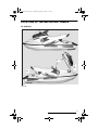
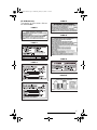
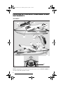
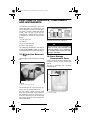
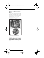
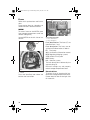
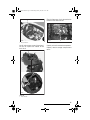
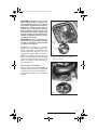
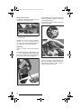
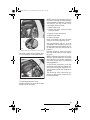
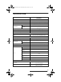
smo2003-004a.fm Page 0 Wednesday, January 22, 2003 1:09 PM SAFETY WARNING Disregarding any of the safety precautions and instructions contained in this Operator’s Guide, the Safety Handbook, the Safety Videocassette and on the on-product warning labels could cause injury, including the possibility of death. The operator has the responsibility to inform passenger(s) of safety precautions. This Operator’s Guide, the Safety Handbook and Safety Videocassette should remain with the craft at the time of resale. DECLARATION OF CONFORMITY 2003 PWC Electro Magnetic Compatibility (EMC) Compliance with 93/68 EC Directive. The 2003 Sea-Doo Personal Watercraft do comply with the above mentioned directive and with 89/336 EC directive in order to match the current European requirements on Personal Watercraft (PWC). Knight’s Spray-Nine† is a trademark of Korkay System Ltd GTX† is a trademark of Castrol Ltd. Used under license The following trademarks are the property of Bombardier Inc. or its subsidiaries: SEA-DOO® BOMBARDIER-ROTAX® BOMBARDIER LUBE® BOMBARDIER Formula XP-S II Synthetic Injection Oil Sea-Doo LKTM Rotax® Printed in Canada (smo2003-004a.fm SH) ®*Trademarks of Bombardier Inc. and/or its subsidiaries. ©2002 Bombardier Inc. All rights reserved. smo2003-004a.fm Page 1 Wednesday, January 22, 2003 1:09 PM NOTE Dear 2003 XP DI watercraft owner. Use the information pertaining to the RX DI model in the 2003 Operator’s Guide (P/N 219 000 290) and then use this supplement to complete the specific information that applies to your XP DI model. 1 smo2003-004a.fm Page 2 Wednesday, January 22, 2003 1:09 PM TABLE OF CONTENTS LOCATION OF THE IMPORTANT LABELS ................................... 3 LOCATION OF CONTROLS, COMPONENTS AND INSTRUMENTS . 6 FUNCTIONS OF CONTROLS, COMPONENTS AND INSTRUMENTS ........................................................................... 8 15) Oil Injection Reservoir Cap................................................................ 8 16) Front Storage Compartment Cover ................................................... 8 26) Mooring Cleats .................................................................................. 9 37) Fuses ................................................................................................. 9 38) Battery ............................................................................................... 9 41) Storage Compartment/Engine Cover Latches ................................... 9 42) Rear Access Cover ............................................................................ 9 43) Automatic Bilge Pump....................................................................... 9 OPERATING INSTRUCTIONS ...................................................... 10 SPECIAL PROCEDURES.............................................................. Towing the Watercraft in Water .............................................................. MAINTENANCE .......................................................................... Lubrication ............................................................................................... Periodic Inspection Chart......................................................................... Fuses ....................................................................................................... TRAILERING, STORAGE AND PRE-SEASON PREPARATION....... Storage .................................................................................................... SPECIFICATIONS........................................................................ 2 12 12 13 13 13 14 16 16 21 smo2003-004b.fm Page 3 Wednesday, January 22, 2003 11:41 AM LOCATION OF THE IMPORTANT LABELS XP DI Models 8 4 2 9 12 3-5 F08L1UL TYPICAL 3 smo2003-004b.fm Page 4 Wednesday, January 22, 2003 11:41 AM Label 1 F08A04L 4 smo2003-004b.fm Page 5 Wednesday, January 22, 2003 11:41 AM Label 5 XP DI Model Only The location of these labels differ on the XP DI model. Label 2 F00A23Y Label 8 F00A22Y Label 3 F00A27Y F02L2D0 Label 9 Label 4 F00A1AY Label 12 F00L29Y F08G04Y F00L2XY 5 smo2003-004b.fm Page 6 Wednesday, January 22, 2003 11:41 AM LOCATION OF CONTROLS, COMPONENTS AND INSTRUMENTS XP DI Model 19 16 23 42 43 26 41 26 18 15 37 38 14 F08L1WL TYPICAL NOTE: Components not shown here are the same as on the RX DI models in the 2003 Sea-Doo Operator’s Guide. 6 smo2003-004b.fm Page 7 Wednesday, January 22, 2003 11:41 AM 14) Fuel Tank Cap 15) Oil Injection Reservoir Cap 16) Front Storage Compartment Cover 18) Tool Kit 19) Air Intake Opening 23) Rear Grab Handle 26) Mooring Cleats 37) Fuses 38) Battery 41) Storage Compartment/Engine Cover Latches 42) Rear Access Cover 43) Automatic Bilge Pump NOTE: Some components shown in the 2003 Sea-Doo Operator’s Guide do not apply to this watercraft. Refer to the following list: 7) Shift Lever 8) Fuel Gauge/Low Oil Warning Light 10) Tachometer 13) Fuel Tank Valve 17) Front Storage Compartment Cover Latch 20) Seat Strap 21) Seat Latch 22) Seat Extension Latch 24) Rear Storage Basket 30) Boarding Step 35) Reverse Gate 39) Side Vanes 7 smo2003-004b.fm Page 8 Wednesday, January 22, 2003 11:41 AM FUNCTIONS OF CONTROLS, COMPONENTS AND INSTRUMENTS The following components have the same operation as explained in the 2003 Operator’s Guide, only their location differ. To know where they are located, refer to the LOCATION OF CONTROLS, COMPONENTS AND INSTRUMENTS section in the previous pages. 14) Fuel Tank Cap 18) Tool Kit 19) Air Intake Opening 23) Rear Grab Handle The following components are specific to the XP DI models. Refer to the following updated texts and/or illustrations. 15) Oil Injection Reservoir Cap Open engine cover and remove storage tray. 1 F08G04Y Reinstall cap and fully tighten it. WARNING Do not overfill. Never exceed the MAX. oil level line. Reinstall cap and fully tighten. Oil is inflammable. Always wipe off any oil spillage from the bilge. 16) Front Storage Compartment Cover It gives access to the front storage compartment. Always relatch cover after closing. The tray is provided with separate compartments. 1 2 F08L0VZ TYPICAL 1. Oil injection reservoir cap To add injection oil in the reservoir, unscrew the cap counterclockwise. Do not overfill. Make sure oil level does not exceed the level shown on the following drawing. Otherwise, siphon out the extra oil. Do not operate the engine when oil level exceeds the recommendation. 8 F08L0UY 1. Fire extinguisher (sold separately) 2. Retaining strap smo2003-004b.fm Page 9 Wednesday, January 22, 2003 11:41 AM WARNING Ensure to properly secure extinguisher with the supplied retaining straps. 42) Rear Access Cover It gives access to the battery, drive system, suspension, exhaust system and bailer pick-ups. Always relatch cover. 26) Mooring Cleats 43) Automatic Bilge Pump All Models These cleats can be temporarily used for docking, while refueling for example. CAUTION: Never use mooring cleats to pull or lift the watercraft. Bilge pump evacuates water from the bilge. When safety lanyard cap is installed on its post, bilge pump automatically turns on. It will remain on until all water is evacuated, if any, then it will shut down automatically. When engine is running, bilge pump will automatically start periodically to evacuate water. F08L0TZ 1 1. Mooring cleats 37) Fuses Fuses are located in engine compartment. Refer to MAINTENANCE for more details. 38) Battery Battery is located in bilge under seat. Refer to SPECIAL PROCEDURES. 41) Storage Compartment/ Engine Cover Latches Pull both latch levers upward in order to open the storage compartment/engine cover. Always relatch cover on both sides. NOTE: Verify periodically the lock pins tightness. Tighten if needed and make sure storage compartment/engine cover latches properly. 9 smo2003-004b.fm Page 10 Wednesday, January 22, 2003 11:41 AM OPERATING INSTRUCTIONS Variable Trim System The variable trim system (VTS) changes the angle of the jet pump nozzle to provide the operator with a fast, effective system to compensate for load, thrust, riding position and water conditions. Correctly adjusted, it can improve handling, reduce porpoising, and position the watercraft at its best riding angle to attain maximum performance. When first using the watercraft, the operator should become familiar with the use of the variable trim system (VTS) at varying speeds and water conditions. A mid-range trim is generally used when cruising. Experience alone will dictate the best trim for the conditions. During the watercraft break-in period, when lower speeds are recommended, it is an excellent opportunity to gain familiarity of trim adjustment and its effects. When the nozzle is positioned in an upward angle, the water thrust directs the bow of the watercraft upward. This position is used to optimize high speed. 10 1 2 8° F08J0AY 3 TYPICAL 1. Push on arrow pointing upward on VTS button 2. Bow up 3. Nozzle up smo2003-004b.fm Page 11 Wednesday, January 22, 2003 11:41 AM 1 2 8° F08J0BY 3 TYPICAL 1. Push on arrow pointing downward on VTS button 2. Bow down 3. Nozzle down 11 smo2003-004b.fm Page 12 Wednesday, January 22, 2003 11:41 AM SPECIAL PROCEDURES Towing the Watercraft in Water It is the same as explained in the 2003 Operator’s Guide. The hose location and routing differs. Refer to the following updated text and illustration. Remove rear access cover. Install pincher as shown. 1 F08E08Y 1. Hose pincher on water supply hose Properly relatch cover. CAUTION: When finished towing the watercraft, hose pincher should be removed before operating it. Failure to do so will result in damage to the engine. 12 smo2003-004b.fm Page 13 Wednesday, January 22, 2003 11:41 AM MAINTENANCE Lubrication Seal Carrier Using a grease gun, carefully lubricate seal carrier of mid bearing until grease is just coming out of seal. 1 F08E0BY 1. Grease seal carrier of mid bearing Periodic Inspection Chart The following is to be added for the XP DI models. PTO flywheel and seal carrier FIRST 10 HOURS L L OPERATOR PROPULSION SYSTEM I: Inspect, verify, clean, adjust, lubricate, replace if necessary C: Clean L: Lubricate R: Replace EVERY 25 HOURS OR 3 MONTHS EVERY 50 HOURS OR 6 MONTHS EVERY 100 HOURS OR 1 YEAR TO BE PERFORMED BY FREQUENCY DESCRIPTION 13 smo2003-004b.fm Page 14 Wednesday, January 22, 2003 11:41 AM Fuses Refer to this updated text and illustrations. Fuses can be found at 2 locations; on the MPEM and in the electrical box. MPEM To access fuses on the MPEM, open front storage compartment cover and remove storage tray. Locate MPEM on the left side of watercraft. 1 2 F1 : FP F2 : ACC F3 : REG F4 : VTS F5 : BAT F6 : INJ 1 15A 2A 25A 7.5A 25A 15A F1 F2 F3 F4 F5 F6 F18H06Y FUSE IDENTIFICATION 1. Fuse identification 2. Fuse description Fuse identification: The fuses (F) are identified from 1 to 6. Fuse description: The fuses are described with abbreviation as follows: FP: Fuel pump ACC: Accessories (information center) REG: Regulator (charging system) VTS: Variable Trim System BAT: Battery INJ: Injection system The fuse description is followed by the ampere rating (A). Reinstall storage tray and properly relatch storage compartment cover. F08H0JY 1. MPEM Fuses are identified, look above and besides the fuse holder. 14 Electrical Box To access fuses in the electrical box, open front storage compartment cover. Locate electrical box on the right side of watercraft. smo2003-004b.fm Page 15 Wednesday, January 22, 2003 11:41 AM Electric bilge pump fuse is located at the bottom of the electrical box. 1 F08H0KY F12H02Y 1 1. Electrical box 1. Electric bilge pump fuse Unclip and remove cover of the electrical box to expose the holder of the main fuse. Properly reinstall removed components. Properly relatch storage compartment cover. 1 2° 1° F18H1BY TYPICAL 1. Fuse holder 15 smo2003-004b.fm Page 16 Wednesday, January 22, 2003 11:41 AM TRAILERING, STORAGE AND PRE-SEASON PREPARATION The information pertaining to trailering, storage and pre-season preparation is similar to the one explained in the 2003 Operator’s Guide, except for the following updated text and illustrations. Storage Engine Draining Remove rear access panel. Check engine drain hose (the lowest one connected to the crankcase cooling outlet). Make sure there is no sand or other particles in it and that it is not obstructed so that water can exit the engine. Clean hose and fitting as necessary. CAUTION: Water in engine drain hose should be free to flow out, otherwise water could be trapped in engine. Should water freeze in engine, severe damage will occur. Check engine drain hose for obstructions. Disconnect the quick connect fitting. Press both tabs and pull fitting. 2 1 F08E0FY 1. Disconnect engine drain hose (crankcase cooling outlet) 2. Air compressor drain line Lower hose as necessary so that draining can take place. Reconnect fitting when done. Also ensure air compressor drain line is not obstructed. Clean as necessary. See illustration above. Antifreezing Protection NOTE: This procedure requires approximately 2.8 L (3 U.S. qt.) of antifreeze. In cool regions where freezing point may be encountered, cooling system should be filled with an equal part of water and antifreeze solution. 16 smo2003-004b.fm Page 17 Wednesday, January 22, 2003 11:41 AM CAUTION: Antifreeze mix must be fed in cooling system. Otherwise remaining water will freeze. This operation requires a good technical knowledge of the cooling system path. If antifreezing is not performed adequately engine/exhaust system may freeze and cause severe engine damage. We strongly recommend this operation be performed by an authorized SEA-DOO dealer. CAUTION: Always use ethylene glycol antifreeze containing corrosion inhibitors specifically recommended for aluminum engines. NOTE: When available, it is recommended to use biodegradable antifreeze compatible with internal combustion aluminum engines. This will contribute to protect the environment. NOTE: The engine will not have to run during this operation but should have been ran before, to exhaust as much water as possible, from cooling system components. 1 2 F08E0GY 1. Water inlet hose 2. Engine cylinder drain hose (coming from underneath engine) Hose Pinchers Installation Some hoses have to be plugged to prevent draining, before filling cooling system jackets with the antifreeze. Install hose pinchers at the following location: 1 F08E0PY 1. Water outlet hose underneath tuned pipe 17 smo2003-004b.fm Page 18 Wednesday, January 22, 2003 11:41 AM Hose Disconnection Disconnect the bottom hose at the water regulator valve on muffler. Pour antifreeze mix in engine until the colored solution appears at cooling system bleed outlet. At this point, install a hose pincher on bleed outlet hose. 1 1 F08E0SY 1. Disconnect the bottom hose from water regulator valve Temporarily install a hose of approximately 1 m (3 ft) in length with a 12.7 mm (1/2 in) internal diameter over the previously disconnected hose. Antifreeze Insert a funnel into the temporary hose. Ensure to hold the funnel approximately 1 m (3 ft) above the deck when pouring the antifreeze to create enough pressure so that it flows properly. F08E0MY 1. Bleed outlet hose Continue to pour until antifreeze appears at the engine drain hose (crankcase cooling outlet). Then, install a hose pincher on this hose. A F08E0TY A. 1 m (3 ft) to ease antifreeze flow 18 smo2003-004b.fm Page 19 Wednesday, January 22, 2003 11:41 AM 1 F08E0JY 1. Engine drain hose (crankcase cooling outlet) Continue to pour until antifreeze flows in air compressor water outlet hose. 1 F08E0EY NOTE: Most of the antifreeze will drain out when removing the hose pinchers. Use a container to recover it. DISPOSE ANTIFREEZE AS PER YOUR LOCAL LAWS AND REGULATIONS. 1. Bleed outlet hose. 2. Engine drain hose (crankcase cooling cover outlet). 3. Engine cylinder drain hose. 4. Water outlet hose. 5. Water inlet hose. Install a temporary hose on the open fitting of the water regulator valve. Pour approximately 200 mL (7 oz) of antifreeze in the temporary hose to allow antifreeze flowing through the water regulator valve and into muffler to protect it. Remove temporary hoses and reconnect the factory hose to water regulator valve. NOTE: Although antifreeze will mainly drain out, the antifreeze has mixed with the water that was possibly trapped in the water jackets and thus preventing freezing problems. At pre-season preparation, drain the remaining antifreeze from cooling system prior to using the watercraft. Ensure no hose pincher was forgotten at storage. The following steps should be performed to provide the watercraft enhanced protection. 1. Air compressor water outlet hose The pouring operation is over. Remove pinchers in this order to allow proper flow of antifreeze. 19 smo2003-004b.fm Page 20 Wednesday, January 22, 2003 11:41 AM Clean the bilge with hot water and detergent or with bilge cleaner. Rinse thoroughly. Lift front end of watercraft to completely drain bilge. If any repairs are needed to body or to the hull contact your authorized SEA-DOO dealer. For paint touch up to mechanical parts use Bombardier spray paint. Final Steps Refer to this updated text. Apply a good quality marine wax to the body. The seat should be partially left opened and the rear access cover and storage tray should be removed during storage. This will avoid engine compartment condensation and possible corrosion. If the watercraft is to be stored outside, cover it with an opaque tarpaulin to prevent sun rays and grime from affecting the plastic components, watercraft finish as well as preventing dust accumulation. CAUTION: The watercraft should never be left in water for storage. Never leave the watercraft stored in direct sunlight. 20 smo2003-004b.fm Page 21 Wednesday, January 22, 2003 11:41 AM SPECIFICATIONS XP DI (6130/6131) ENGINE Engine type Induction type Rotax 947, 2-stroke Reed valve Exhaust system Exhaust valve Water cooled/water injected with regulator Rotax Adjustable Variable Exhaust (RAVE) Type Lubrication Oil type Number of cylinders Displacement Oil injection BOMBARDIER Formula XP-S II synthetic injection oil 2 951.2 cm3 (58 in3) Rev limiter setting COOLING 7300 ± 50 RPM Open circuit. Direct flow from propulsion unit Type ELECTRICAL Magneto generator output Ignition system type Spark plug Make and type Gap Starting system Battery Fuse 270 W @ 6000 RPM Digital inductive NGK, ZFR4F 1.1 mm (.043 in) Electric starter with reduction gear 12 V, 19 A•h Battery Main 25 A 30 A Charging system (REG) VTS system 25 A 7.5 A Information center (ACC) Injection system (INJ) 15 A Fuel pump (FP) Bilge pump 15 A 3A 2A FUEL SYSTEM Fuel type Fuel injection Regular unleaded gasoline with 87 octane minimum (R+M)/2 Orbital direct fuel injection, twin throttle body (46 mm (1.81 in)) 21 smo2003-004b.fm Page 22 Wednesday, January 22, 2003 11:41 AM XP DI (6130/6131) Bombardier Formula pump PROPULSION Propulsion system Jet pump type Transmission Axial flow, single stage Direct drive/split front and rear Reverse system No SEA-DOO synthetic polyolester oil SAE 75W90 GL5 Jet pump oil type Pivoting angle of direction (nozzle) Minimum required water level for jet pump DIMENSIONS Number of passengers ➀ ~ 20° 90 cm (3 ft) 2 Overall length Overall width 272 cm (107 in) 112 cm (44.1 in) Overall height Weight 104 cm (40.6 in) 274 kg (605 lb) Load limit (passengers + luggage) CAPACITIES 181 kg (400 lb) Fuel tank Fuel tank reserve (from low level signal Oil injection tank Impeller shaft reservoir 51 L (13.5 U.S. gal) 9.8 L (2.6 U.S. gal) Capacity 4 L (1.1 U.S. gal) 100 mL (3.4 U.S. oz) Oil level Up to plug ➀ Refer to load limit. BOMBARDIER INC. reserves the right to make changes in design and specifications and/or to make additions to, or improvements in its products without imposing any obligation upon itself to install them on its products previously manufactured. 22