1
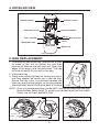
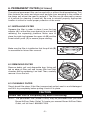
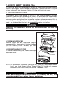
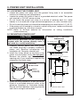
CENTRAL VACUUM
POWER UNIT
! HOUSEHOLD TYPE !
CX450 & CXKIT450A
MODEL NO. SFDB-DA
AB0020
HOMEOWNERS OPERATING INSTRUCTIONS
READ AND SAVE THESE INSTRUCTIONS
Broan-NuTone Canada Inc.;
Mississauga, Ontario
www.broan.ca
888-882-7626
To register this product, visit www.broan.ca
30042423 Rev. E
IMPORTANT SAFETY INSTRUCTIONS
READ ALL INSTRUCTIONS BEFORE USING THIS APPLIANCE.
When using an electric appliance, basic precautions should always be followed,
including the following:
WARNING
!
TO REDUCE THE RISK OF FIRE, ELECTRIC SHOCK, OR PERSONAL INJURY:
• Do not use on wet surfaces or outdoors.
• Do not allow to be used as a toy. Close attention is necessary when used by or
near children.
• Use only as described in this manual. Use only manufacturer's recommended
attachments.
• Do not put any object into openings. Do not use with any opening blocked; keep
free of dust, lint, hair, and anything that may reduce air flow.
• Keep hair, loose clothing, fingers and all parts of body away from openings and
moving parts.
• Do not pick up anything that is burning or smoking, such as cigarettes, matches,
or hot ashes.
• Do not use without dustbag or filter in place.
• Do not use to blow leaves or debris.
• Do not vacuum liquids or fine powders (such as drywall dust).
• Do not put any object on the unit.
• Ensure air flows freely to both side intake vents and exhausts unobstructed
from top outlet.
• Do not install the unit horizontally.
• Do not use the pail as a wash pail.
• Do not use the pail as a stool.
• Turn off all controls before unplugging.
• Use extra care when cleaning on stairs.
• Avoid picking up sharp objects.
• Do not use to pick up flammable or combustible liquids such as gasoline or use
in areas where they may be present.
• Do not use with damaged cord or plug. If appliance is not working as it should,
if it has been dropped, damaged, left outdoors, or dropped into water, return it
to a service center.
• Do not unplug the unit by pulling on cord. To unplug, grasp the plug, not the cord.
• Do not handle plug or appliance with wet hands.
• Connect to a properly grounded outlet only. See grounding instructions on
page 9.
• Any servicing other than that recommended in this manual should be
performed by an authorized service facility.
• We recommend that your unit be inspected by a specialized technician once a
year.
SAVE THESE INSTRUCTIONS
-2-
1. OPERATION
The power unit is located away from the everyday living areas of your home — usually
in the garage, basement, or utility room. Through a network of strong, lightweight
tubing, the power unit connects to inlets strategically placed throughout your
home. When you are ready to clean, attach the wand and cleaning tool onto the
end of the hose. Open the inlet cover and insert the end of the hose into the inlet.
Use the ON/OFF switch on the hose handle* to activate the power unit. As you
vacuum, dirt and dust are transported to the power unit where they remain in a
bag or in the debris pail.
NOTE: The rocker switch on the front of the power unit can be used to turn the
power unit on.
Use the cleaning tools as you would for any other vacuum cleaner. Avoid picking
up pine needles, coffee sticks and other similar objects. These kinds of objects
may become lodged in the hose or tubing.
2. VACUUM POWER CONTROL
The hose handle* is equipped with a control ring to
regulate the air flow. The control ring covers a “bleeder”
hole. Open the hole to reduce the suction for cleaning
draperies, small rugs, and other light fabrics. Some
very thick, plush carpets with high density yarns also
require reduced suction to make the nozzle easier to
push. Be sure to close the control ring completely
over the hole to produce the maximum power required
for most other cleaning tasks.
AA0009
CONTROL
RING
3. WHEN TO CHANGE BAG OR EMPTY DEBRIS PAIL**
With a 6 U.S. Gallons capacity, under normal conditions the bag/debris pail
requires changing/emptying approximately twice a year. If the bag/debris pail is
filled, you will notice a complete loss of vacuum in the system. Unless this loss of
vacuum is caused by a blockage in the system, changing the bag or emptying the
debris pail will solve the problem.
NOTE: Even if not filled to capacity, if the bag seems tightly stretched when
removing the debris pail, changing the bag will prevent it from tearing.
* The accessory kit is included only with the CXKIT450A model. See section 11
on page 10 for more details.
** In order to use the debris pail to collect debris, the optional permanent filter has
to be installed in the power unit (see permanent filter instructions on page 5).
-3-
4. DETAILED VIEW
ROCKER
EXHAUST
SWITCH
SECONDARY
INLET
FILTER
VACUUM
DISPOSABLE
CHAMBER
INLET
CHAMBER
OUTLET
BAG
ADAPTER
LATCH
BAG
DEBRIS
PAIL
AL0003
5. BAG REPLACEMENT
1. To remove the disposable bag, release both latches
on sides of the unit by pulling out and then
pushing up. Remove the pail from unit. Grasp the
edges of the bags’ collar and pull down. The bag
will slide off easily. Do not pull on the bag.
2. Unfold new bag.
3. Grasp collar where indicated on the bag and insert
over bag adapter. Be careful not to tear the bag.
Ensure that the collar is positioned between the
taper ring and the bag stopper on the bag adapter
(see illustration below). Put the pail back in its place
AA0004
NOTE : A set of 3 replacement bags (model 391C) may be purchased from you local
Broan-NuTone Sales Outlet. To locate your nearest Broan-NuTone Sales
Outlet, call toll free 1-888-882-7626.
TAPER
AO0024
RING
BAG
STOPPER
-4-
AO0025
6. PERMANENT FILTER (OPTIONAL)
The optional permanent filter can be used with or without the disposable bag. This
filter protects the motor and stops small particles from escaping to the outside of
the power unit wihout the need to replace it. The filter can be removed by means
of a pull-tab for cleaning (if need be). Be sure to reinstall properly. Appropriate
location is critical to insure proper protection of the motor.
6.1 INSTALLING FILTER
Squeeze the filter in order to place it over the bag
adapter (A). Let the filter prop against the unit wall by
releasing the squeezing pressure. Make sure to
place the rigid ring between the upper rib (B) and the
three bottom posts (C) to ensure proper sealing.
A
B
C
AO0028
Make sure the filter is installed so that the pull tab (D)
is accessible for future filter removal.
D
AA0005
6.2 REMOVING FILTER
Remove debris pail and disposable bag. Using pull
tab on edge of filter, pull and loosen filter from inlet
chamber wall by squeezing it on itself. Then, carefully
remove it from the unit.
AO0027
6.3 CLEANING FILTER
Simply brush filter clean. If the filter is excessively soiled, wash in a mild detergent
and let it dry completely before putting it back in its place.
CAUTION
Ensure that filter is completely dry before reinstalling.
NOTE: The permanent filter (model PF450) may be purchased from you local
Broan-NuTone Sales Outlet. To locate your nearest Broan-NuTone Sales
Outlet, call toll free 1-888-882-7626.
-5-
7. HOW TO EMPTY DEBRIS PAIL
To empty the debris pail, release both latches on sides of the unit by pulling out
and then pushing up. Holding the pail by the latches, lower it from unit. Carry pail
to trash receptacle and dispose of debris. Put the pail back in its place.
8. SECONDARY FILTER
A secondary safety filter, located at the top of the vacuum chamber provides
protection against dirt being pulled into the motor if the disposable bag or permanent
filter should accidentally be torn. This filter should be checked and cleaned if
necessary, when replacement bag is installed or when optional permanent filter is
removed for cleaning. Simply brush filter clean. If the filter is excessively soiled,
wash in a mild detergent and let it dry completely before reinstalling.
CAUTION
Operating the power unit without the secondary filter will void the
warranty.
8.1 REMOVING FILTER
Remove debris pail and disposable bag or
permanent filter. Remove both locking sleeves
from the retaining hooks. Carefully pull filter
down to remove.
RETAINING
HOOKS
8.2 REINSTALLING FILTER
To reinstall the secondary filter, reverse the steps
described above.
SECONDARY
FILTER
LOCKING
SLEEVES
AO0029
NOTE: A replacement secondary filter (part no. 10941310) may be purchased
from your local Broan-NuTone Sales Outlet. To locate your nearest
Broan-NuTone Sales Outlet, call toll free 1-888-882-7626.
! WARNING
When performing installation, servicing or cleaning the unit, it is
recommended to wear safety glasses and gloves.
-6-
9. POWER UNIT INSTALLATION
9.1 LOCATING THE POWER UNIT
• Locate the power unit away from the general living area in an accessible
location for cleaning and maintenance.
• Locate the power unit within 6 feet of a grounded electrical outlet. The power
unit requires a 120 VAC power source.
• Do not locate the power unit close to a source of extreme heat (i.e.: water
heater) or in an area with a high ambient temperature (i.e.: attic, furnace room).
• Do not locate the power unit where the temperature can drop below 0°C (32°F).
• If the power unit is located in a closet or a small utility room, make sure the area
is well-ventilated (i.e.: with door louvers).
NOTE: Refer to NuTone website for information on tubing installation
(www.nutone.ca).
9.2 MOUNTING POWER UNIT
CAUTION
Make sure to assemble the wall mounting
bracket with the screws directly onto a
wall stud for a solid installation.
MINIMUM WALL CLEARANCE
DIMENSIONS
14" MIN.
PVC TUBING STRAP
INLET
INLET
EXHAUST
1. Carefully remove debris pail from power
unit. Make sure bag is properly installed in
power unit. Remove accessories and
installation kit. Securely reinstall pail.
2. Install the 3-way elbow on the back of the
power unit and press firmly (do not glue).
Remove the plastic cap from the inlet
opening only if your installation requires the
connection into both inlets.
TOP VIEW
CEILING
12" MINIMUM TO CEILING
WALL BRACKET
EXHAUST
3-WAY ELBOW
DO NOT GLUE
22"
REMOVE
PLASTIC CAP
(IF NEED BE)
41"
INLET
INLET
60"
AO0030
3. Install mounting bracket on a wall stud within
6 feet of a grounded electrical outlet, at the
distances specified on illustration beside.
Ensure that wall between mounting bracket
and inlet is straight and leveled.
FRONT VIEW
18" MINIMUM ABOVE FLOOR
FLOOR
AD0040A
-7-
9. POWER UNIT INSTALLATION (CONT’D)
RETAINING SCREW
LOCATIONS
4. Use the mounting bracket as a template to
mark the position of its screws. Drill the
upper and lower screw holes into the stud
using a 3/16” drill bit.
MOUNTING BRACKET
CENTER OPENING
AA0006
5. Using a Phillips screwdriver, secure the mounting bracket to the wall with
2 no. 14 x 2” screws (included). Make sure that the bracket is tight against the
wall.
6. Hang the power unit by inserting its back hook
into the center opening of its mounting bracket.
Make sure hook is securely engaged in bracket.
Secure the power unit to the mounting bracket,
with the provided no. 6 x 3/8” screw and washer
into the small remaining hole using a Phillips
screwdriver (see illustrations beside).
WASHER/SCREW
LOCATION
WASHER/SCREW
INSTALLED
TOP
TOP
AD0041
AD0042
OF THE
UNIT
OF THE
UNIT
7. Run house vacuum line up to the 3-way elbow behind the power unit. Secure
house vacuum line to the appropriate 3-way elbow opening with PVC glue (do
not glue the 3-way elbow to the power unit).
8. Connect muffler (if desired) and exhaust tubing to exhaust outlet on top of the
power unit. The exhaust should not be vented into a wall, ceiling or concealed
space in the house. Exterior vented exhaust lines should end using model V142
wall cap.
NOTE: Exhausting the power unit to the outside is recommended for optimal
performance but is not required.
9. Once everything is in place, secure the
piping (near the elbow) to the wall using the
included PVC strap.
AO0031
-8-
PVC
STRAP
10. GROUNDING INSTRUCTIONS
! WARNING
Improper connection of the equipment-grounding conductor can result in a
risk of electric shock. Check with a qualified electrician or service person if
you are in doubt as to whether the outlet is properly grounded. Do not
modify the plug provided with the appliance — if it will not fit the outlet,
have a proper outlet installed by a qualified electrician.
This appliance must be grounded. If it should malfunction or break down, grounding
provides a path of least resistance for electric current, to reduce the risk of electric
shock. This appliance is equipped with a cord having an equipment-grounding
conductor and grounding plug. The plug must be inserted into an appropriate outlet
that is properly installed and grounded in accordance with all local codes and
ordinances.
This appliance is for use on a nominal 120-volt circuit and has a grounding attachment
plug that looks like the plug illustrated below. Make sure that the appliance is
connected to an outlet having the same configuration as the plug. No adapter
should be used with this appliance.
1. Using pliers, install both crimp connectors (included) to low voltage wire
(22 gauge minimum, 2-conductor, model V133, not included).
2. Connect low voltage wire to tabs located on outside of the power unit.
3. The power unit is equipped with a 6-foot grounded cord. Plug cord into
120-volt grounded receptacle.
CRIMP
POWER
CONNECTORS
LOW VOLTAGE TABS
UNIT
OVERCURRENT
PROTECTOR BUTTON
POWER
CORD
GROUNDED
OUTLET BOX
INLET
GROUNDED
LEADS
OUTLETS
GROUNDING
MODEL V133 (22/2)
PIN
LOW VOLTAGE WIRE
TO
OTHER
INLETS
AE0031
INLET
INLET
INLET
NOTE: INLET LEADS TO BE CONNECTED TO POWER UNIT LOW VOLTAGE TABS USING CRIMP CONNECTORS
(INCLUDED) AND LOW VOLTAGE HARNESS.
-9-
11. ACCESSORY KIT
MODEL
CX450
CXKIT450A
ACCESSORY KIT
NOT included
Included
Accessory kit includes:
• Multi-Surface tool for carpet, tile, wood and ceramic.
AA0007
• 30’ Low-voltage crushproof hose with 360° rotating handle.
Deluxe hose hanger included.
AA0008
• Standard tool set:
12” wide hard floor brush with swivel
neck.
Aluminum ratchet telescopic wand;
from a collapsed length of 22” to an
extended length of 39”.
Natural bristle upholstery tool.
Square faced dusting brush.
10” crevice tool with notched end.
Clip-on caddy.
AA0003
- 10 -
12. TROUBLESHOOTING GUIDE
PROBLEMS
POSSIBLE
1. Loss or
decrease
of vacuum
occurs.
• The plastic cap is not installed on • Place the included plastic cap on
the unused inlet.
the unused inlet opening.
• Debris pail or disposable bag is • Change disposable bag or empty
completely full.
debris pail as described on page 4.
NOTE: Clean secondary filter if
necessary.
• Obstruction in the hose. A blockage • Disconnect the hose from the wall
inlet and insert a blunt instrument
in the hose can be determined by
into the hose — slightly smaller in
inserting the hose into any wall
diameter — such as a flexible
inlet and, while power unit is
garden hose. Push the garden
running, check each additional
hose through the cleaning system
inlet for normal suction by holding
hose until the obstruction has
the palm of your hand over the
been cleared.
open inlet. If normal suction is felt
at all other inlets, insert the hose
into a second inlet. If the blockage
still exists it is located in the hose.
However, if the blockage does not
occur when the hose is changed,
the blockage is probably located in
the tubing system leading to the
original inlet.
• Obstruction in the tubing system • Insert hose end into any inlet with
power unit running, place the palm
inside the walls.
of your hand over the opposite
end of the hose. When you can
feel the suction increase, hold
your hand over the hose end for a
few seconds and then quickly
remove your hand. This procedure
repeated several times should
clear the obstruction. If the
blockage is not cleared, contact
your nearest Service Center.
• Wall inlet cover not properly • Check all wall inlet covers to be sure
they are closed and sealed tightly.
sealed.
• Defective inlet. Check other wall inlets. • Replace defective wall inlet.
• Power unit overcurrent protector • Turn the unit off by using the
has been activated.
power switch on the unit. Check
the overcurrent protector button
located on the left side of the
power unit (push to reset the
system). Turn unit back on.
• Blown fuse or tripped circuit • Replace fuse or reset circuit
breaker on house electrical panel.
breaker on house electrical panel.
• Thermoprotector
has
been • Turn the unit off by using the
power switch on the unit. Wait
activated.
30 minutes to let the unit cool
down. Turn unit back on.
• Defective hose.
• Replace hose as required.
2. Power unit
does not
start or
stops
suddenly.
POSSIBLE REMEDY
CAUSES
3. Power unit • An electrical short has occurred • A complete check of all wall inlets
fails to stop
somewhere in the system.
and power unit low voltage control
when the
leads connections.
hose is
Contact your authorized Service
removed.
Center.
- 11 -
BROAN-NUTONE CANADA INC.
CENTRAL VACUUM POWER UNIT
LIMITED LIFETIME WARRANTY
Broan-NuTone Canada warrants to the original consumer purchaser that its central vacuum power unit will
be free from defects in materials and workmanship for as long as you own your home in which it was
originally installed with the exception of the motor and electronic components which will be warranted for
three (3) years. The first year of this warranty covers the parts and labor in an authorized service center.
THERE ARE NO OTHER WARRANTIES, EXPRESSED OR IMPLIED, INCLUDING, BUT NOT LIMITED
TO, IMPLIED WARRANTIES OF MERCHANTABILITY OR FITNESS FOR A PARTICULAR PURPOSE.
During these time periods, Broan-NuTone Canada will, at its option, repair or replace the power unit or
part without charge, which is found to be defective under normal use and service. THIS WARRANTY DOES
NOT APPLY TO THE INSTALLATION OR THE PARTS USED IN THE INSTALLED TUBING SYSTEM. All
central vacuum hoses, electric or air-driven brushes, filters, attachments and accessories are warranted for
one (1) year from the original purchase date with the exception to consumables such as light bulbs and belts.
This warranty does not cover (a) normal maintenance and service or (b) any products or parts which have
been subject to misuse, negligence, accident, improper maintenance or repair (other than by Broan-NuTone
Canada or an authorized representative), faulty installation or installation contrary to recommended
installation instructions.
The duration of any implied warranty is limited to the period as specified for the express warranty.
BROAN-NUTONE CANADA’S OBLIGATION TO REPAIR OR REPLACE, AT BROAN-NUTONE CANADA’S
OPTION, SHALL BE THE PURCHASER'S SOLE AND EXCLUSIVE REMEDY UNDER THIS WARRANTY.
BROAN-NUTONE CANADA SHALL NOT BE LIABLE FOR INCIDENTAL, CONSEQUENTIAL OR SPECIAL
DAMAGES ARISING OUT OF OR IN CONNECTION WITH PRODUCT USE OR PERFORMANCE. Please
do not return your unit to place of purchase. Please visit www.nutone.ca for your closest service center. You
may also call 1-888-882-7626 for the name of an authorized representative in your area. This warranty
supersedes all prior warranties.
To qualify for warranty service, you must notify Broan-NuTone Canada at the address or telephone number
stated below. We will then forward you the authorized service depot in your area. You will be required to
present evidence of the original purchase date.
Date of Installation
Builder or Installer
Model Number and Product Description
Serial number
IF YOU NEED ASSISTANCE OR SERVICE:
For the location of your nearest Broan-NuTone Canada Inc. dealer:
Dial Toll Free: 1-888-882-7626
Please be prepared to provide:
Product model number • Date and proof of purchase • The nature of the difficulty
Broan-NuTone Canada Inc.
1140 Tristar Drive, Mississauga, Ontario L5T 1H9
www.nutone.ca
Product specifications subject to change without notice.
- 12 -