1
DIVAR IP 6000 2U
DIP-6080-00N, DIP-6082-8HD, DIP-6083-8HD
en
Installation Manual
DIVAR IP 6000 2U
Table of Contents | en
3
Table of contents
1
Safety precautions
5
1.1
General safety precautions
5
1.2
Electrical safety precautions
6
1.3
ESD precautions
7
1.4
Operating precautions
7
1.5
Important notices
8
1.6
FCC and ICES compliance
8
2
System overview
9
2.1
Chassis features
9
2.2
Chassis components
9
2.2.1
Chassis
10
2.2.2
Backplane
10
2.2.3
Fans
10
2.2.4
Mounting rails
10
2.2.5
Power supply
10
2.2.6
Air shroud
10
2.3
System interface
10
2.3.1
Control panel buttons
11
2.3.2
Control panel LEDs
12
2.3.3
Drive carrier LEDs
12
3
Chassis setup and maintenance
13
3.1
Removing the chassis cover
13
3.2
Installing hard drives
14
3.2.1
Removing hard drive trays
14
3.2.2
Installing a hard drive
15
3.3
Installing an optional floppy or fixed hard drive
16
3.4
Installing or replacing a DVD-ROM drive
17
3.5
Replacing the internal transcoder device
17
3.6
Replacing or installing the front port panel
17
3.7
Installing the motherboard
18
3.8
Installing the air shroud
18
3.9
System fans
19
3.10
Power supply
20
3.10.1
Replacing the power supply
21
3.10.2
Replacing the power distributor
22
4
Rack installation
23
4.1
Unpacking the system
23
4.2
Preparing for setup
23
4.2.1
Choosing a setup location
23
4.2.2
Rack precautions
23
4.2.3
General system precautions
24
4.2.4
Rack mounting considerations
24
4.3
Rack mounting instructions
24
4.3.1
Separating the sections of the rack rails
25
4.3.2
Installing the inner rails
26
4.3.3
Installing the outer rails to the rack
26
4.3.4
Installing the chassis into the rack
27
Bosch Sicherheitssysteme GmbH
Installation Manual
2014.01 | V2 | DOC
4
en | Table of Contents
DIVAR IP 6000 2U
4.3.5
Installing the chassis into a Telco rack
27
4.4
Turning on the system
28
5
Appendix
29
5.1
Motherboard
29
5.1.1
Motherboard layout
29
5.1.2
Motherboard component overview
30
5.1.3
Motherboard features
32
5.1.4
Block diagram
34
5.2
Chipset overview
34
5.3
PC health monitoring
35
5.4
Power configuration settings
35
5.5
Power supply
36
5.6
Super I/O
36
5.7
iSCSI support
36
5.8
Overview of the Nuvoton BMC controller
37
5.9
RAID disaster recovery
37
5.9.1
Multiple disks failed - theory
38
5.9.2
Multiple disks failed - practice
43
5.9.3
Foreign configuration disk appears in the Windows GUI after booting
46
5.9.4
MegaCLI Commandline Utility
47
2014.01 | V2 | DOC
Installation Manual
Bosch Sicherheitssysteme GmbH
DIVAR IP 6000 2U
Safety precautions | en
5
Safety precautions
1
Observe the safety precautions in this chapter.
1.1
General safety precautions
Follow these rules to ensure general safety:
–
Keep the area around the system clean and free of clutter.
–
Place the chassis top cover and any system components that have been removed away
from the system or on a table so that they won't accidentally be stepped on.
–
While working on the system, do not wear loose clothing such as neckties and
unbuttoned shirt sleeves, which can come into contact with electrical circuits or be
pulled into a cooling fan.
–
Remove any jewelry or metal objects from your body, which are excellent metal
conductors that can create short circuits and harm you if they come into contact with
printed circuit boards or areas where power is present.
–
After accessing the inside of the system, close the system back up and secure it to the
rack unit after ensuring that all connections have been made.
–
The system is heavy when fully loaded. When lifting the system, two people at either end
should lift slowly with their feet spread out to distribute the weight. Always keep your
back straight and lift with your legs.
Warning!
Interruption of mains supply:
!
Voltage is applied as soon as the mains plug is inserted into the mains socket.
However, for devices with a mains switch, the device is only ready for operation when the
mains switch (ON/OFF) is in the ON position. When the mains plug is pulled out of the
socket, the supply of power to the device is completely interrupted.
Warning!
Removing the housing:
!
To avoid electric shock, the housing must only be removed by qualified service personnel.
Before removing the housing, the plug must always be removed from the mains socket and
remain disconnected while the housing is removed. Servicing must only be carried out by
qualified service personnel. The user must not carry out any repairs.
Warning!
Power cable and AC adapter:
!
When installing the product, use the provided or designated connection cables, power cables
and AC adaptors. Using any other cables and adaptors could cause a malfunction or a fire.
Electrical Appliance and Material Safety Law prohibits the use of UL or CSA-certified cables
(that have UL/CSA shown on the code) for any other electrical devices.
Bosch Sicherheitssysteme GmbH
Installation Manual
2014.01 | V2 | DOC
6
en | Safety precautions
DIVAR IP 6000 2U
Warning!
Lithium battery:
Batteries that have been inserted wrongly can cause an explosion. Always replace empty
!
batteries with batteries of the same type or a similar type recommended by the manufacturer.
Handle used batteries carefully. Do not damage the battery in any way. A damaged battery
may release hazardous materials into the environment.
Dispose of empty batteries according to the manufacturer's instructions.
Warning!
!
Handling of lead solder materials used in this product may expose you to lead, a chemical
known to the State of California to cause birth defects and other reproductive harm.
Notice!
Electrostatically sensitive device:
To avoid electrostatic discharges, the CMOS/MOSFET protection measures must be carried
out correctly.
When handling electrostatically sensitive printed circuits, grounded anti-static wrist bands
must be worn and the ESD safety precautions observed.
Notice!
Installation should only be carried out by qualified customer service personnel in accordance
with the applicable electrical regulations.
Disposal
Your Bosch product has been developed and manufactured using highquality materials and components that can be reused.
This symbol means that electronic and electrical devices that have reached
the end of their working life must be disposed of separately from
household waste.
In the EU, separate collecting systems are already in place for used
electrical and electronic products. Please dispose of these devices at your
local communal waste collection point or at a recycling center.
1.2
Electrical safety precautions
Basic electrical safety precautions should be followed to protect you from harm and the
system from damage:
–
Be aware of the locations of the power on/off switch on the chassis as well as the room's
emergency power-off switch, disconnection switch or electrical outlet. If an electrical
accident occurs, you can then quickly remove power from the system.
–
Do not work alone when working with high voltage components.
–
Power should always be disconnected from the system when removing or installing main
system components, such as the motherboard or memory modules. When disconnecting
power, you should first turn off the system and then unplug the power cords from all the
power supply modules in the system.
–
When working around exposed electrical circuits, another person who is familiar with the
power-off controls should be nearby to switch off the power if necessary.
2014.01 | V2 | DOC
Installation Manual
Bosch Sicherheitssysteme GmbH
DIVAR IP 6000 2U
Safety precautions | en
–
7
Use only one hand when working with powered-on electrical equipment. This is to avoid
making a complete circuit, which will cause electrical shock. Use extreme caution when
using metal tools, which can easily damage any electrical components or circuit boards
they come into contact with.
–
The power supply power cords must include a grounding plug and must be plugged into
grounded electrical outlets. The unit has more than one power supply cord. Disconnect
both power supply cords before servicing to avoid electrical shock.
–
Mainboard replaceable soldered-in fuses: Self-resetting PTC (Positive Temperature
Coefficient) fuses on the mainboard must be replaced by trained service technicians only.
The new fuse must be the same or equivalent as the one replaced. Contact technical
support for details and support.
Caution!
Mainboard Battery: There is a danger of explosion if the onboard battery is installed upside
!
down, which will reverse its polarities. This battery must be replaced only with the same or
an equivalent type recommended by the manufacturer (CR2032). Dispose of used batteries
according to the manufacturer's instructions.
Caution!
!
DVD-ROM Laser: This system comes without a DVD-ROM drive but if added: To prevent direct
exposure to the laser beam and hazardous radiation exposure, do not open the enclosure or
use the unit in any unconventional way.
1.3
ESD precautions
Electrostatic Discharge (ESD) is generated by two objects with different electrical charges
coming into contact with each other. An electrical discharge is created to neutralize this
difference, which can damage electronic components and printed circuit boards. The
following measures are generally sufficient to neutralize this difference before contact is made
to protect your equipment from ESD:
–
Do not use mats designed to decrease electrostatic discharge as protection from
electrical shock. Instead, use rubber mats that have been specifically designed as
electrical insulators.
–
Use a grounded wrist strap designed to prevent static discharge.
–
Keep all components and printed circuit boards (PCBs) in their antistatic bags until ready
for use.
–
–
Touch a grounded metal object before removing the board from the antistatic bag.
Do not let components or printed circuit boards come into contact with your clothing,
which may retain a charge even if you are wearing a wrist strap.
–
Handle a board by its edges only. Do not touch its components, peripheral chips, memory
modules or contacts.
–
When handling chips or modules, avoid touching their pins.
–
Put the mainboard and peripherals back into their antistatic bags when not in use.
–
For grounding purposes, make sure your computer chassis provides excellent
conductivity between the power supply, the case, the mounting fasteners and the
mainboard.
1.4
Operating precautions
The chassis cover must be in place when the system is operating to assure proper cooling. Out
of warranty damage to the system can occur if this practice is not strictly followed.
Bosch Sicherheitssysteme GmbH
Installation Manual
2014.01 | V2 | DOC
8
en | Safety precautions
DIVAR IP 6000 2U
Note:
Please handle used batteries carefully. Do not damage the battery in any way. A damaged
battery may release hazardous materials into the environment. Do not discard a used battery
in the garbage or a public landfill. Please comply with the regulations set up by your local
hazardous waste management agency to dispose of your used battery properly.
1.5
Important notices
Accessories - Do not place this unit on an unstable stand, tripod, bracket,
or mount. The unit may fall, causing serious injury and/or serious damage to
the unit. Use only with the cart, stand, tripod, bracket, or table specified by
the manufacturer. When a cart is used, use caution and care when moving
the cart/apparatus combination to avoid injury from tip-over. Quick stops,
excessive force, or uneven surfaces may cause the cart/unit combination to
overturn. Mount the unit per the manufacturer's instructions.
1.6
FCC and ICES compliance
(only for U.S.A. and Canada)
This equipment has been tested and found to comply with the limits for a Class A digital
device pursuant to Part 15 of the FCC Rules. These limits are designed to provide reasonable
protection against harmful interference when the equipment is operated in a commercial
environment. This equipment generates, uses, and can radiate radio frequency energy and, if
not installed and used in accordance with the manufacturer’s instruction manual, may cause
harmful interference with radio communications. Operation of this equipment in a residential
area is likely to cause harmful interference, in which case you will be required to correct the
interference at your own expense.
2014.01 | V2 | DOC
Installation Manual
Bosch Sicherheitssysteme GmbH
DIVAR IP 6000 2U
2
System overview | en
9
System overview
DIVAR IP 6000 is an affordable, simple and reliable all-in-one recording management solution
for network surveillance systems of up to 64 cameras. Powered by VRM (Video Recording
Manager) software, the system is an intelligent IP storage device that eliminates the need for
separate NVR (Network Video Recorder) server and storage hardware.
The system is a 2U rack mount unit that combines advanced recording management and stateof-the-art iSCSI storage into a single cost-effective, plug and play IP recording appliance for ITminded customers seeking for a state-of-the-art “second generation” NVR recording solution.
The DIVAR IP 6000 2U chassis features a unique and highly-optimized design. The chassis is
equipped with high efficiency power supply.
High performance fans provide ample optimized cooling for memory modules. Hot-swap drive
bays offer maximum storage capacity in a 1U form factor.
DIVAR IP 6000 features:
–
Instant real time access to video
View high quality HD video despite low or limited bandwidth connections. Dynamic
Transcoding technology ensures that you can view your video immediately — anytime,
anywhere.
–
Remote viewing
DIVAR IP 6000 comes with our advanced Video Client for remote viewing. Video Client is a
Windows PC application for live viewing and playback including Configuration Manager.
Configuration Manager allows the settings of the DIVAR IP 6000 be configured. A standalone archive player will allow archive playback and authentication without any other
workstation software.
For information on supported hardware, see the datasheet for DIVAR IP 6000 in the Bosch
Online Product Catalog.
2.1
Chassis features
The DIVAR IP 6000 2U high-performance chassis includes the following features:
–
CPU
The chassis supports a Dual-core Xeon processor.
–
Hard drives
The chassis features 8 slots for U320 SCSI or SAS/SATA drives. These drives are hot
swappable. Once setup correctly, these drives can be removed without powering down
the server. In addition, these drives support SAF-TE (SCSI) and SES2 (SAS/SATA)
–
I/O expansion slots
Each chassis model includes seven low-profile I/O expansion slots.
–
Peripheral drives
Each chassis supports one slim DVD-ROM Drive (not included) and one slim Floppy Drive.
These drives allow you to quickly install or save data.
–
Other features
Other onboard features are included to promote system health. These include various
three cooling fans, a convenient power switch, reset button, and 5 LED indicators.
2.2
Chassis components
This chapter describes the most common components included with your chassis. For more
information, see the installation instructions detailed later in this manual.
Bosch Sicherheitssysteme GmbH
Installation Manual
2014.01 | V2 | DOC
10
en | System overview
DIVAR IP 6000 2U
Chassis
2.2.1
The chassis includes 8 hard drive bays. The chassis accepts a 2U backplane, 3 fans and
2 power supplies.
Backplane
2.2.2
Each chassis comes with a 2U backplane. The backplane accepts SAS/SATA hard drives.
Warning!
!
Use caution when servicing and working around the backplane. Hazardous voltage or energy
is present on the backplane when the system is operating. Do not touch the backplane with
any metal objects and make sure no ribbon cables touch the backplane.
2.2.3
Fans
The chassis supports 3 system fans that are powered from the motherboard. These fans are
2U high and are powered by 3-pin connectors.
2.2.4
Mounting rails
The unit can be placed in a rack for secure storage and use. To setup your rack, follow the
step-by-step instructions included in this manual.
2.2.5
Power supply
Each chassis model includes 2 high-efficiency power supplies (redundant). In the unlikely
event your power supply fails, replacement is simple and can be accomplished without tools.
2.2.6
Air shroud
Air shrouds are shields, usually plastic, which conduct the airflow directly to where it is
needed. Always use the air shroud included with your chassis.
2.3
System interface
There are several LEDs on the front and rear of the chassis. The LEDs show the over-all status
of the system and the activity and health of specific components.
2014.01 | V2 | DOC
Installation Manual
Bosch Sicherheitssysteme GmbH
DIVAR IP 6000 2U
System overview | en
11
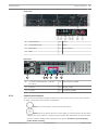
Front view:
1
Power Failure
5
Power
2
Overheat/Fan Fail
6
Reset
3
NIC1/NIC2
7
Power on/off
4
HDD
Rear view:
3
2
1
4
2x mains connection 100 – 240 VAC,
1
5
6
4
Serial interface COM1
50 - 60 Hz
2.3.1
2
2x PS/2
5
Monitor (VGA)
3
2x USB
6
2x Ethernet (RJ45)
Control panel buttons
There are two push-buttons located on the front of the chassis. These are (in order from left
to right) a reset button and a power on/off button.
–
Reset: The reset button is used to reboot the system.
–
Power: The main power switch is used to apply or remove power from the power
supply to the server system. Turning off system power with this button removes the main
power but keeps standby power supplied to the system. Therefore, you must unplug
system before servicing.
Bosch Sicherheitssysteme GmbH
Installation Manual
2014.01 | V2 | DOC
12
en | System overview
2.3.2
DIVAR IP 6000 2U
Control panel LEDs
The control panel located on the front of the chassis has LEDs to provide you with critical
information related to different parts of the system. This section explains what each LED
indicates.
–
Power failure: A flashing LED indicates a power failure in the power supply.
–
Overheat/fan fail: A flashing LED indicates a fan failure.
When continuously on (not flashing) the LED indicates an overheat condition, which may
be caused by cables obstructing the airflow in the system or the ambient room
temperature being too warm. Check the routing of the cables and make sure all fans are
present and operating normally. You should also check to make sure that the chassis
covers are installed. Finally, verify that the heat sinks are installed properly.
This LED will remain flashing or on as long as the fan failure/overheat condition exists.
–
NiC2: A flashing LED indicates network activity on GLAN2.
–
NIC1: A flashing LED indicates network activity on GLAN1.
–
HDD: A flashing LED indicates IDE channel activity in the SAS/SATA drive, SCSI
drive, and/or DVD-ROM drive activity.
–
Power: Indicates power is being supplied to the system's power supply units.
This LED should normally be illuminated when the system is operating.
2.3.3
Drive carrier LEDs
Your chassis uses SAS/SATA.
SAS/SATA drives
Each SAS/SATA drive carrier has two LEDs.
–
Green: Each Serial ATA drive carrier has a green LED. When illuminated, this green LED
(on the front of the SATA drive carrier) indicates drive activity. A connection to the SATA
backplane enables this LED to blink on and off when that particular drive is being
accessed.
–
Red: The red LED indicates a SAS/SATA drive failure. If one of the SAS/SATA drives fail,
you should be notified by your system management software.
2014.01 | V2 | DOC
Installation Manual
Bosch Sicherheitssysteme GmbH
DIVAR IP 6000 2U
Chassis setup and maintenance | en
13
Chassis setup and maintenance
3
This chapter covers the steps required to install components and perform maintenance on the
chassis.
Caution!
!
Review the warnings and precautions listed in the manual before setting up or servicing this
chassis.
Related topics:
Safety precautions, page 5
Rack precautions, page 23
General system precautions, page 24
3.1
Removing the chassis cover
To remove the chassis cover:
1. Remove the two screws on each side of the cover, which secure the cover to the chassis.
2.
Press the release tabs to remove the cover from the locked position. Press both tabs at
the same time.
3.
Once the top cover is released from the locked position, slide the cover toward the rear
of the chassis.
4.
Lift the cover off the chassis.
Notice!
Except for short periods of time, do NOT operate the server without the cover in place. The
chassis cover must be in place to allow proper airflow and prevent overheating.
Bosch Sicherheitssysteme GmbH
Installation Manual
2014.01 | V2 | DOC
14
en | Chassis setup and maintenance
3.2
DIVAR IP 6000 2U
Installing hard drives
This chapter describes the removing and installing of hard drives.
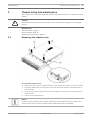
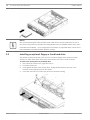
3.2.1
Removing hard drive trays
The drives are mounted in drive carriers to simplify their installation and removal from the
chassis. These carriers also help promote proper airflow for the drive bays.
1
Drive carrier
2
Dummy drive
To remove hard drive trays from the chassis:
1. Press the release button on the drive carrier. This extends the drive carrier handle.
2.
Use the handle to pull the drive out of the chassis.
Notice!
Except for short periods of time (swapping hard drives), do not operate the unit with the
hard drives removed from the bays.
2014.01 | V2 | DOC
Installation Manual
Bosch Sicherheitssysteme GmbH
DIVAR IP 6000 2U
3.2.2
Chassis setup and maintenance | en
15
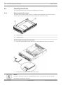
Installing a hard drive
The drives are mounted in drive carriers.
To install a hard drive to the hard drive carrier:
1. Remove the screws securing the dummy drive to the carrier.
2.
Remove the dummy drive from the carrier.
3.
Install a new drive into the carrier with the printed circuit board side facing down so that
the mounting holes align with those in the carrier.
4.
Secure the hard drive by tightening all 6 screws.
Drive carrier
1
5.
2
SAS/SATA hard drive
Replace the drive carrier into the chassis bay. Make sure that the drive carrier handle is
completely closed.
Bosch Sicherheitssysteme GmbH
Installation Manual
2014.01 | V2 | DOC
16
en | Chassis setup and maintenance
DIVAR IP 6000 2U
Notice!
We recommend using the respective Bosch hard disk drives. The hard disk drives as one of
the critical component are carefully selected by Bosch based on available failure rates. HDD –
not delivered from Bosch – are not supported. Information on supported HDDs can be found
in the datasheet in the Bosch Online Product Catalog.
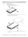
3.3
Installing an optional floppy or fixed hard drive
The chassis models include two open slots for an optional floppy drive, and/or hard disk
drive(s). To utilize these slots, the dummy drive and the slot cover must be removed.
To remove the dummy drive or hard disk drive:
1. Disconnect the chassis from any power source.
2.
Press the release tab.
3.
Push against the back of the dummy drive, sliding the dummy drive and slot cover
forward, out through the front of the chassis.
4.
2014.01 | V2 | DOC
Insert the drive into rear of the open slot and connect the wiring.
Installation Manual
Bosch Sicherheitssysteme GmbH
DIVAR IP 6000 2U
3.4
Chassis setup and maintenance | en
17
Installing or replacing a DVD-ROM drive
The chassis models are not shipped with a DVD-ROM from factory as the OS is pre-installed on
the disk on module drive (DOM).
If you must install a new or replace a faulty DVD ROM, observe the following instructions.
1
DVD-ROM
2
Front port panel
To install or replace a DVD-ROM drive:
1. Turn off the unit and if necessary, remove the unit from the rack.
2.
Remove the chassis cover.
3.
Unplug the drives power and data cables from the motherboard and/or backplane.
4.
If you are adding a new DVD-ROM drive:
Remove the mini-bezel (grate) from the drive bay The bezel can be removed by pulling out
the hard drive beneath the DVD-ROM drive bay, then pulling the mini-bezel forward.
If you are replacing a drive:
Locate the locking tab at the rear (left hand side when viewed from the front) of the DVDROM drive. Push the tab toward the drive and push the drive unit out the front of the
chassis.
5.
Insert the new drive unit in the slot until the tab locks in place.
6.
Reconnect the data and power cables.
7.
Replace the chassis cover. replace the unit in the rack, if necessary, then turn on the
system.
3.5
Replacing the internal transcoder device
The chassis model includes an internal USB transcoder device.
Notice!
To replace or install the transcoder device, please apply to one of the Bosch RMA helpdesks.
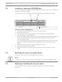
3.6
Replacing or installing the front port panel
If you must install a new or replace a damaged front port panel, observe the following
instructions.
Bosch Sicherheitssysteme GmbH
Installation Manual
2014.01 | V2 | DOC
18
en | Chassis setup and maintenance
1
DIVAR IP 6000 2U
DVD-ROM
2
Front port panel
To replace or install the front port panel:
1. Turn off and unplug the unit.
2.
Remove the chassis cover.
3.
Disconnect the power and data cables from the front port panel to other chassis
components including the motherboard and backplane.
4.
Remove the old port panel by depressing the release tab, then pulling the unit out of the
chassis.
3.7
5.
Insert the new front port panel unit in the slot until the tab locks into place.
6.
Connect the data and power cables to the backplane and motherboard.
Installing the motherboard
Motherboard problems will be handled by trained support people only.
3.8
Installing the air shroud
Air shrouds concentrate airflow to maximize fan efficiency. The air shroud does not require
screws to set up.
2014.01 | V2 | DOC
Installation Manual
Bosch Sicherheitssysteme GmbH
DIVAR IP 6000 2U
Chassis setup and maintenance | en
19
To install the air shroud:
4 Place air shroud in the chassis. The air shroud fits behind the two fans closest to the
power supply.
Note: If a 16 DIMM (13.68" x 13") motherboard is used, it is necessary to use the optional
MCP-310-82502-0N air shroud.
To check the air flow:
1. Make sure there are no objects to obstruct airflow in and out of the chassis. In addition, if
you are using a front bezel, make sure the bezel's filter is replaced periodically.
2.
Do not operate the system without drives or drive trays in the drive bays. Use only
3.
Make sure no wires or foreign objects obstruct air flow through the chassis. Pull all
recommended material.
excess cabling out of the airflow path or use shorter cables. The control panel LEDs
inform you about system status.
See also:
–
System interface, page 10.
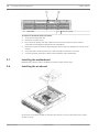
3.9
–
Air shroud, page 10.
–
Rack installation, page 23.
System fans
The system fans provide cooling for the chassis. These fans circulate air through the chassis as
a means of lowering the chassis internal temperature.
1
1
Bosch Sicherheitssysteme GmbH
Release Tab
Installation Manual
2014.01 | V2 | DOC
20
en | Chassis setup and maintenance
DIVAR IP 6000 2U
Warning!
!
The fans might still be turning when you remove the fan assembly from the chassis. Keep
fingers, screwdrivers, and other objects away from the openings in the fan assembly's
housing.
To replace a system fan:
1. If necessary, open the chassis while the power is running to determine which fan has
failed. (Never run the system for an extended period of time with the chassis open.)
2.
Turn off the power to the system and unplug the power cord from the outlet.
3.
Remove the failed fan's wiring from the motherboard.
4.
Press the fan release tab to lift the failed fan from the chassis and pull it completely from
the chassis.
5.
Place the new fan into the vacant space in the housing while making sure the arrows on
the top of the fan (indicating air direction) point in the same direction as the arrows on
the other fans.
6.
Reconnect the power cord, turn on the system and make sure that the fan is working
properly before replacing the chassis cover.
3.10
Power supply
The chassis has two redundant power supplies. The power supplies are auto-switching
capable. This enables the power supplies to automatically sense and operate at a 100 V to
240 V input voltage.
LED status:
–
Amber lighted LED: The power supply is off.
–
2014.01 | V2 | DOC
Green lighted LED: The power supply is operating.
Installation Manual
Bosch Sicherheitssysteme GmbH
DIVAR IP 6000 2U
Chassis setup and maintenance | en
21
Warning!
!
Redundant power supplies
This unit might have more than one power supply connection. To de-energize the unit, remove
all connections.
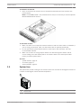
3.10.1
Replacing the power supply
The power supply can be replaced without turning off the system if a redundant power supply
is available. Replacement units can be ordered directly from Bosch RMA desk.
To replace the power supply:
1. Only for units with one power supply: Turn off the unit and unplug the power cord.
2.
Push the release tab (on the back of the power supply) as illustrated.
3.
Pull the power supply out using the handle provided.
4.
Replace the failed power module with the same model.
5.
Push the new power supply module into the power bay until you hear a click.
6.
Plug the AC power cord back into the module and turn on the unit.
Bosch Sicherheitssysteme GmbH
Installation Manual
2014.01 | V2 | DOC
22
en | Chassis setup and maintenance
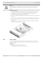
3.10.2
DIVAR IP 6000 2U
Replacing the power distributor
Redundant server chassis that are 2U or greater require a power distributor. The power
distributor provides failover and power supply redundancy.
To replace the power distributor:
1. Turn off the unit and remove the plug from the wall socket or power strip.
2.
Remove all cable connections to the power supply from the motherboard, backplane, and
other components. Also, remove both power supplies.
3.
Locate the power distributor between the power supply and the fan row.
4.
Remove the three screws securing the power supply.
5.
Gently pull the power distributor from the chassis. Gently guide all the cables through the
power distributor housing.
6.
Slide the new power distributor module into the power distributor housing. Make that
you slide the cables through the bottom of the housing.
7.
Reconnect all the power cables, replace the power supply, and insert the plug into the
wall.
2014.01 | V2 | DOC
Installation Manual
Bosch Sicherheitssysteme GmbH
DIVAR IP 6000 2U
Rack installation | en
23
Rack installation
4
This chapter provides a quick setup checklist to get your chassis up and running. Following
these steps in the order given should enable you to have the system operational within a
minimum amount of time.
Unpacking the system
4.1
You should inspect the box the chassis was shipped in and note if it was damaged in any way.
If the chassis itself shows damage, file a damage claim with the carrier who delivered it and
notify the respective Bosch RMA desk.
You will also need it placed near at least one grounded power outlet.
Due to the weight of the system: After opening the top of the shipping box, one person should
stand at either end and lift the disk array out together.
Be sure to read the safety precautions.
4.2
Preparing for setup
The box the system is shipped in includes a rack mount kit, which you will need to install the
system into the rack.
Follow the steps in the order given to complete the installation process in a minimum amount
of time. Read this section before you begin the installation procedure outlined in the sections
that follow.
4.2.1
Choosing a setup location
–
Situate the system in a clean, dust-free area that is well ventilated. Avoid areas where
heat, electrical noise and electromagnetic fields are generated. Place the system near a
grounded power outlet.
–
Leave approximately 25 inches clearance in front of the rack to be able to open the front
door completely.
–
Leave approximately 30 inches of clearance in the back of the rack to allow for sufficient
airflow and ease in servicing.
–
Install the system only in a Restricted Access Location (dedicated equipment rooms,
service closets and the like).
Notice!
This product is not suitable for use with visual display work place devices acccording to §2 of
the the German Ordinance for Work with Visual Display Units.
4.2.2
Rack precautions
Warning!
!
To prevent bodily injury when mounting or servicing this unit in a rack, you must take special
precautions to ensure that the system remains stable. The following guidelines are provided
to ensure your safety:
–
Ensure that the leveling jacks on the bottom of the rack are fully extended to the floor
with the full weight of the rack resting on them.
–
In single rack installations, attach stabilizers to the rack.
Bosch Sicherheitssysteme GmbH
Installation Manual
2014.01 | V2 | DOC
24
en | Rack installation
–
DIVAR IP 6000 2U
If the rack is provided with stabilizing devices, install the stabilizers before mounting or
servicing the unit in the rack.
–
This unit should be mounted at the bottom of the rack if it is the only unit in the rack.
–
When mounting this unit in a partially filled rack, load the rack from the bottom to the top
with the heaviest component at the bottom of the rack.
–
In multiple rack installations, couple the racks together.
–
Always make sure the rack is stable before extending a component from the rack.
–
Extend only one component at a time - extending two or more simultaneously may cause
the rack to become unstable.
4.2.3
General system precautions
–
Review the electrical and general safety precautions that came with the components you
are adding to your chassis.
–
Determine the placement of each component in the rack before installing the rails.
–
Install the heaviest components on the bottom of the rack first, and then work up.
–
Use a regulating uninterruptible power supply (UPS) to protect the system from power
surges, voltage spikes if you want to keep your system operating in case of a power
failure.
–
Allow the SATA hard drives and power supply modules to cool before touching them.
–
Always keep the rack’s front door and all panels and components on the system closed
when not servicing to maintain proper cooling.
See also:
–
Safety precautions, page 5
4.2.4
Rack mounting considerations
Ambient operating temperature
If installed in a closed or multi-unit rack assembly, the ambient operating temperature of the
rack environment may be greater than the ambient temperature of the room. Therefore,
consideration should be given to installing the equipment in an environment compatible with
the manufacturer’s maximum rated ambient temperature (Tmra).
Reduced airflow
Equipment should be mounted into a rack so that the amount of airflow required for safe
operation is not compromised.
Mechanical loading
Equipment should be mounted into a rack so that a hazardous condition does not arise due to
uneven mechanical loading.
Circuit overloading
Consideration should be given to the connection of the equipment to the power supply
circuitry and the effect that any possible overloading of circuits might have on overcurrent
protection and power supply wiring. Appropriate consideration of equipment nameplate
ratings should be used when addressing this concern.
Reliable ground
A reliable ground must be maintained at all times. To ensure this, the rack itself should be
grounded. Particular attention should be given to power supply connections other than the
direct connections to the branch circuit (i.e. the use of power strips, etc.).
4.3
Rack mounting instructions
This section provides information on installing the chassis into a rack unit. There are a variety
of rack units on the market, which may mean the assembly procedure will differ slightly. You
should also refer to the installation instructions that came with the rack unit you are using.
2014.01 | V2 | DOC
Installation Manual
Bosch Sicherheitssysteme GmbH
DIVAR IP 6000 2U
Rack installation | en
25
Notice!
This rail will fit a rack between 26" and 33.5" deep.
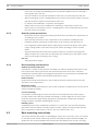
4.3.1
Separating the sections of the rack rails
The chassis package includes two rail assemblies in the rack mounting kit. Each assembly
consists of two sections:
–
an inner fixed chassis rail that secures directly to the chassis
–
an outer fixed rack rail that secures directly to the rack itself.
To separate the inner and outer rails:
1. Locate the rail assembly in the chassis packaging.
2.
Extend the rail assembly by pulling it outward.
3.
Press the quick-release tab.
4.
Separate the inner rail extension from the outer rail assembly.
Bosch Sicherheitssysteme GmbH
Installation Manual
2014.01 | V2 | DOC
26
en | Rack installation
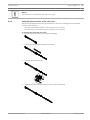
4.3.2
DIVAR IP 6000 2U
Installing the inner rails
The chassis includes a set of inner rails in two sections: inner rails and inner rail extensions.
The inner rails are pre-attached to the chassis, and do not interfere with normal use of the
chassis if you decide not to use a server rack. The inner rail extension is attached to the inner
rail to mount the chassis in the rack.
3
1
2
To install the inner rails:
1. Place the inner rail extensions on the side of the chassis aligning the hooks of the chassis
with the rail extension holes. Make sure the extension faces "outward" just like the preattached inner rail.
4.3.3
2.
Slide the extension toward the front of the chassis.
3.
Secure the chassis with 2 screws as illustrated.
4.
Repeat steps for the other inner rail extension.
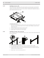
Installing the outer rails to the rack
Outer rails attach to the rack and hold the chassis in place. The outer rails extend between 30
inches and 33 inches.
3
1
2
To install the outer rails to the rack:
1. Secure the back end of the outer rail to the rack, using the screws provided.
2.
Press the button where the two outer rails are joined to retract the smaller outer rail.
3.
Hang the hooks of the rails onto the rack holes and if desired, use screws to secure the
front of the outer rail onto the rack.
4.
2014.01 | V2 | DOC
Repeat steps 1-3 for the remaining outer rail.
Installation Manual
Bosch Sicherheitssysteme GmbH
DIVAR IP 6000 2U
Rack installation | en
27
Locking Tabs
Both chassis rails have a locking tab, which serves two functions. The first is to lock the
system into place when installed and pushed fully into the rack, which is its normal position.
Secondly, these tabs also lock the system in place when fully extended from the rack. This
prevents the system from coming completely out of the rack when you pull it out for servicing.
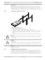
Installing the chassis into the rack
4.3.4
To install the chassis into a rack:
1. Extend the outer rails as illustrated above.
2.
Align the inner rails of the chassis with the outer rails on the rack.
3.
Slide the inner rails into the outer rails, keeping the pressure even on both sides. When
the chassis has been pushed completely into the rack, it should click into the locked
position.
4.
Optional screws may be used to secure the to hold the front of the chassis to the rack.
Warning!
!
Do not pick up the unit with the front handles. The handles are designed to pull the system
from a rack only.
Warning!
Stability hazard
!
Before sliding the unit out for servicing make sure that the rack stabilizing mechanism is in
place, or the rack is bolted to the floor. Failure to stabilize the rack can cause the rack to tip
over.
See also:
Rack precautions, page 23
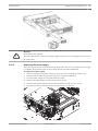
4.3.5
Installing the chassis into a Telco rack
To install the chassis into a Telco type rack, use two L-shaped brackets on either side of the
chassis (four in total). First, determine how far the chassis will extend out the front of the
rack. Larger chassis should be positioned to balance the weight between front and back. If a
bezel is included on the chassis, remove it. Then attach the two front brackets to each side of
Bosch Sicherheitssysteme GmbH
Installation Manual
2014.01 | V2 | DOC
28
en | Rack installation
DIVAR IP 6000 2U
the chassis, then the two rear brackets positioned with just enough space to accommodate
the width of the Telco rack. Finish by sliding the chassis into the rack and tightening the
brackets to the rack.
4.4
Turning on the system
The last thing to be done is to provide input power to the system.
To turn on the system:
1. Plug the power cord from the power supply unit into a high-quality power strip that offers
protection from electrical noise and power surges. We recommended using an
uninterruptible power supply (UPS).
2.
2014.01 | V2 | DOC
Press the power button on the control panel to turn on the system.
Installation Manual
Bosch Sicherheitssysteme GmbH
DIVAR IP 6000 2U
5
Appendix | en
29
Appendix
This chapter gives information for supporting and troubleshooting.
5.1
Motherboard
All graphics shown in this chapter were based upon the latest PCB Revision available at the
time of publishing of the manual. The motherboard you've received can differ from the
graphics shown in this chapter.
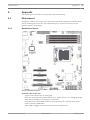
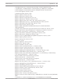
5.1.1
Motherboard layout
Figure 5.1: Motherboard layout
Important notes to the user:
–
Jumpers not indicated are for testing only.
–
When LE2 (Onboard Power LED Indicator) is on, system power is on. Unplug the power
cable before installing or removing any components.
–
All systems have a SATA DOM connected to Serial ATA ports (I-SATA-5) with a small
power connector (DOM PWR).
–
SATA-DOM: Is plugged in connector I-SATA-5 on the motherboard.
Bosch Sicherheitssysteme GmbH
Installation Manual
2014.01 | V2 | DOC
30
en | Appendix
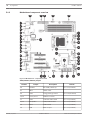
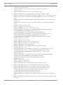
5.1.2
DIVAR IP 6000 2U
Motherboard component overview
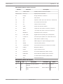
Figure 5.2: Motherboard – component overview
X8SIL/X8SIL-F/X8SIL-V jumpers
Jumper
Number
2014.01 | V2 | DOC
Description
Default
38
JPUSB1
BP USB0/1 Wake-up
42
JBT1
CMOS Clear
40
JPES
Energy Saving Feature
13,14
JI2C1/JI2C2
SMB to PCI Slots
17
JPG1
Onboard VGA Enable
Pins 1-2 (Enabled)
11,12
JPL1/JPL2
LAN1/LAN2 Enable
Pins 1-2 (Enabled)
24
JPT1
TPM Enable
Pins 1-2 (Enabled)
10
JPB
BMC Jumper
Pins 1-2 (Enabled)
Installation Manual
Pins 1-2 (Enabled)
Pins 2-3 (Disabled)
Bosch Sicherheitssysteme GmbH
DIVAR IP 6000 2U
Appendix | en
31
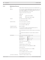
X8SIL/X8SIL-F/X8SIL-V headers/connectors
Number
Connector
Description
4,16
COM1/COM2
COM1/2 Serial connection headers
33,32,27,23,7
Fans 1~5
System/CPU fan headers
34
Floppy
Floppy Disk Drive connector
5
JAR
Alarm Reset
30
JD1
Speaker header (Pins 3/4: Internal, 1~4:External)
28
JF1
Front Panel Control header
41
JL1
Chassis Intrusion header
29
JLED
Power LED Indicator header
37
JPW1
24-pin ATX main power connector (required)
36
JPW2
+12V 8-pin CPU power connector (required)
1
KB/Mouse
Keyboard/mouse connectors
8,9
LAN1~LAN2,
Gigabit Ethernet (RJ45) ports (LAN1/LAN2)
21
I-SATA 0~5
Serial ATA ports (X8SIL has 4 Serial ATA Ports)
2
IPMI
IPMI LAN Port (X8SIL-F Only)
35
JPI2C
PWR supply (I2C) System Management Bus
31
SPKR1
Internal speaker/buzzer
25
T-SGPIO-0/1
Serial General Purpose IO headers (for SATA)
3,20
USB0/1
Backplane USB 0/1
19
USB 4
Type A USB Connector
18
USB 10/11
Front Panel USB header (X8SIL-F Only)
22
DOM PWR
Disk-On-Module (DOM) Power Connector
39
JTPM
Trusted Platform Module (TPM) Header
6
VGA
Onboard Video Port
X8SIL/X8SIL-F/X8SIL-V LED indicators
Number
26
LED
LE4
Description
Onboard Standby PWR LED
Color/State
Status
Green: Solid on
PWR On
Yellow: Blinking
IPMI: Normal
Indicator
15
LE7
IPMI Heartbeat LED (X8SIL-F
Only)
Bosch Sicherheitssysteme GmbH
Installation Manual
2014.01 | V2 | DOC
32
en | Appendix
5.1.3
DIVAR IP 6000 2U
Motherboard features
CPU
Single Intel Xeon 3400 series processor in an LGA1156 socket.
Memory
Four (4) 240-pin, DDR3 SDRAM DIMM sockets with support for
up to 16GB of UDIMM or up to 32GB of RDIMM memory (ECC/
DDR3 1333/1066/800 MHz memory only.)
Supports dual-channel memory bus
DIMM sizes
Chipset
UDIMM
1 GB, 2 GB, and 4GB
RDIMM
1 GB, 2GB, 4GB, and 8GB
Intel 3420 Chipset (X8SIL-F/X8SIL-V)
Intel 3400 Chipset (X8SIL)
Expansion Slots
Two (2) PCI Express 2.0 (x8) slot
One (1) PCI Express x4 (x8) slot
One (1) 32-bit PCI 33MHz slot
Integrated Graphics
Matrox G200eW
Network Connections
Two Intel 82574L Gigabit (10/100/1000 Mb/s) Ethernet
Controllers for LAN 1 and LAN 2 ports.
Two (2) RJ-45 Rear IO Panel Connectors with Link and Activity
LEDs
Single Realtek RTL8201N PHY to support IPMI 2.0 (X8SIL-F
Only)
I/O Devices
SATA Connections (X8SIL-F/X8SIL-V Only)
SATA Ports
Six (6)
RAID (Windows)
RAID 0, 1, 5, 10
RAID (Linux)
RAID 0, 1, 10
SATA Connections (X8SIL Only)
SATA Ports
Four (4)
Integrated IPMI 2.0 (X8SIL-F Only)
IPMI 2.0 supported by the WPCM450 Server BMC
Floppy Disk Drive
One (1) floppy drive interface (up to 1.44 MB)
USB Devices (X8SIL Only)
Two (2) USB ports on the rear IO panel
One (1) Type A internal connector
I/O Devices (Continued)
2014.01 | V2 | DOC
USB Devices (X8SIL-F/X8SIL-V Only)
Installation Manual
Bosch Sicherheitssysteme GmbH
DIVAR IP 6000 2U
Appendix | en
33
Two (2) USB ports on the rear IO panel
Four (4) USB header connectors for front access
One (1) Type A internal connector
Keyboard/Mouse
PS/2 Keyboard/Mouse ports on the I/O backplane
Serial (COM) Ports
Two (2) Fast UART 16550 Connections: one 9-pin RS-232 port
and one header
Super I/O
Winbond Super I/O 83627DHG-P
BIOS
32 Mb SPI AMI BIOS SM Flash BIOS
DMI 2.3, PCI 2.3, ACPI 1.0/2.0/3.0, USB Keyboard and SMBIOS
2.5
Power Configuration
ACPI/ACPM Power Management
Main switch override mechanism
Keyboard Wake-up from Soft-Off
Internal/External moder ring-on
Power-on mode for AC power recovery
PC Health Monitoring
CPU Monitoring
Onboard voltage monitors for CPU core, +3.3V, +5V, +/-12V,
+3.3V Stdby, +5V Stdby, VBAT, HT, Memory, Chipset
CPU 3-Phase switching voltage regulator
CPU/System overheat LED and control
CPU Thermal Trip support
Thermal Monitor 2 (TM2) support
Fan Control
Fan status monitoring with firmware 4-pin (Pulse Width
Modulation) fan speed control
Low noise fan speed control
System Management
PECI (Platform Environment Configuration Interface) 2.0
support
System resource alert via Supero Doctor III
SuperoDoctor III, Watch Dog, NMI
Chassis Intrusion Header and Detection
CD Utilities
Bosch Sicherheitssysteme GmbH
BIOS flash upgrade utility
Installation Manual
2014.01 | V2 | DOC
34
en | Appendix
DIVAR IP 6000 2U
Drivers and software for Intel 3400/3420 chipset utilities
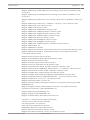
5.1.4
Other
ROHS 6/6 (Full Compliance, Lead Free)
Dimensions
Micro ATX form factor, 9.6" x 9.6"
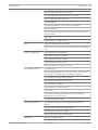
Block diagram
The following graphic shows the block diagram of the motherboard.
Figure 5.3: Block diagram
Notice!
This is a general block diagram and may not exactly represent the features on your
motherboard. See the Motherboard Features pages for the actual specifications of each
motherboard.
5.2
Chipset overview
The X8SIL/X8SIL-F/X8SIL-V supports the Intel Xeon 3400 processor series. Built upon the
functionality and the capability of the single-chip Intel 3400 chipset, the X8SIL/X8SIL-F/X8SILV motherboard provides the performance and feature set required for single-processor-based
systems with configuration options optimized for entry-level server platforms.The high-speed
Direct Media Interface (DMI) featured in the Intel 3400/3420 chipset enables the X8SIL/X8SILF/X8SIL-V motherboard to offer a high-speed Direct Media Interface (DMI) for chip-to-chip true
isochronous communication with the processor. This feature allows the X8SIL/X8SIL-F/X8SILV to achieve up to 10 Gb/s of software-transparent data transfer on each direction, achieving
2014.01 | V2 | DOC
Installation Manual
Bosch Sicherheitssysteme GmbH
DIVAR IP 6000 2U
Appendix | en
35
better performance than comparable systems. The X8SIL/X8SIL-F/X8SIL-V also features a TCO
timer (to enable the system to recover from a software/hardware lock), ECC Error Reporting,
Function Disable and Intruder Detect.
Intel 3400/3420 chipset features
–
Direct Media Interface (up 10 Gb/s transfer, Full Duplex)
5.3
–
Intel Matrix Storage Technology and Intel Rapid Storage Technology
–
Dual NAND Interface
–
Intel I/O Virtualization (VT-d) Support
–
Intel Trusted Execution Technology Support
–
PCI Express 2.0 Interface (up to 5.0 GT/s)
–
SATA Controller (up to 3G/s)
–
Advanced Host Controller Interface (AHCI)
PC health monitoring
This section describes the PC health monitoring features of the X8SIL/X8SIL-F/X8SIL-V. These
features are supported by an onboard System Hardware Monitor chip.
Recovery from AC power loss
BIOS provides a setting for you to determine how the system will respond when AC power is
lost and then restored to the system. You can choose for the system to remain powered off (in
which case you must hit the power switch to turn it back on) or for it to automatically return
to a power on state. The default setting is Last State.
Onboard voltage monitoring
The onboard voltage monitor will scan the following voltages continuously: CPU core, +3.3V,
+5V, +/-12V, +3.3V Stdby, +5V Stdby, VBAT, HT, Memory, Chipset. Once a voltage becomes
unstable, it will give a warning or send an error message to the screen. Users can adjust the
voltage thresholds to define the sensitivity of the voltage monitor by using SD III.
Fan status monitor with software
PC health monitoring can check the RPM status of the cooling fans via Supero Doctor III.
CPU overheat LED and control
This feature is available when the user enables the CPU overheat warning feature in the BIOS.
This allows the user to define an overheat temperature. When this temperature reaches this
pre-defined overheat threshold, the CPU thermal trip feature will be activated and it will send
a signal to the buzzer and, at the same time, the CPU speed will be decreased.
5.4
Power configuration settings
This section describes the features of your motherboard that deal with power and power
settings.
Slow blinking LED for suspend-state indicator
When the CPU goes into a suspend state, the chassis power LED will start blinking to indicate
that the CPU is in the suspend mode. When the user presses any key, the CPU will wake-up
and the LED indicator will automatically stop blinking and remain on.
BIOS support for USB keyboard
If the USB keyboard is the only keyboard in the system, it will function like a normal keyboard
during system boot-up.
Main switch override mechanism
When an ATX power supply is used, the power button can function as a system suspend
button. When the user presses the power button, the system will enter a SoftOff state. The
monitor will be suspended and the hard drive will spin down. Pressing the power button again
to wake-up the whole system. During the SoftOff state, the ATX power supply provides power
Bosch Sicherheitssysteme GmbH
Installation Manual
2014.01 | V2 | DOC
36
en | Appendix
DIVAR IP 6000 2U
the system to keep the required circuitry "alive". In case the system malfunctions and you
want to turn off the power, just press and hold the power button for 4 seconds. The power
will turn off and no power will be provided to the motherboard.
5.5
Power supply
A stable power source is necessary for proper and reliable operation. It is even more
important for processors that have high CPU clock rates of 1 GHz and faster.
The X8SIL/X8SIL-F/X8SIL-V accommodates ATX12V standard power supplies. Although most
power supplies generally meet the specifications required by the CPU, some are inadequate. A
2-Amp of current supply on a 5V Standby rail is strongly recommended.
It is strongly recommended that you use a high quality power supply that meets ATX12V
standard power supply Specification 1.1 or later. It is also required that the 12V 8-pin power
connection (JPW2) be used for adequate power supply. In areas where noisy power
transmission is present, you may choose to install a line filter to shield the computer from
noise. It is recommended that you also install a power surge protector to help avoid problems
caused by power surges.
DIVAR IP 6000 does not have a function to determine pre-failure of a power supply. The power
supply will have the LED to show it is “OK” or “failed” by showing the color green or amber for
the respective status. When the power supply fails, it shows amber, when it is functioning
correctly it shows green.
5.6
Super I/O
The disk drive adapter functions of the Super I/O chip include a floppy disk drive controller
that is compatible with industry standard 82077/765, a data separator, write precompensation circuitry, decode logic, data rate selection, a clock generator, drive interface
control logic and interrupt and DMA logic. The wide range of functions integrated onto the
Super I/O greatly reduces the number of components required for interfacing with floppy disk
drives. The Super I/O supports two 360 K, 720 K, 1.2 M, 1.44 M or 2.88 M disk drives and data
transfer rates of 250 Kb/s, 500 Kb/s or 1 Mb/s.
It also provides two high-speed, 16550-compatible serial communication ports (UARTs). Each
UART includes a 16-byte send/receive FIFO, a programmable baud rate generator, complete
modem control capability and a processor interrupt system. Both UARTs provide legacy speed
with baud rate of up to 115.2 Kbps as well as an advanced speed with baud rates of 250 K,
500 K, or 1 Mb/s, which support higher speed modems.
The Super I/O provides functions that comply with ACPI (Advanced Configuration and Power
Interface), which includes support of legacy and ACPI power management through a SMI or
SCI function pin. It also features auto power management to reduce power consumption.
5.7
iSCSI support
The X8SIL/X8SIL-F/X8SIL-V motherboard supports the iSCSI Internet Protocol. iSCSI is an IP
networking standard used to link and manage data storage, and transfer data across the
internet and private intranets through long distance. iSCSI can be used to transmit data over
local area networks (LANs), wide area networks (WANs), or the Internet. It can enable
location-independent data storage and retrieval.
iSCSI allow clients to issue SCSI commands to remote SCSI storage devices and allow data
centers to consolidate remote storage devices into storage arrays, giving an illusion of locallyattached disks to host servers. Unlike fiber-optic networks that require special cabling, iSCSI
can run over long distance using existing networks.
2014.01 | V2 | DOC
Installation Manual
Bosch Sicherheitssysteme GmbH
DIVAR IP 6000 2U
Appendix | en
37
For the X8SIL/X8SIL-F/X8SIL-V motherboard, iSCSI is supported on LAN 1. This can be
enabled through the BIOS: Advanced => PCI/PnP Configuration => Onboard LAN1 Option ROM
Select.
5.8
Overview of the Nuvoton BMC controller
The Nuvoton WPCM150 is a combined Baseboard Management Controller and 2D/VGAcompatible Graphics Core with PCI interface, Virtual Media and Keyboard, and a Keyboard/
Video/Mouse Redirection (KVMR) module.
The WPCM150 interfaces with the host system via a PCI interface to communicate with the
Graphics core. It supports USB 2.0 and 1.1 for remote keyboard/mouse/virtual media
emulation. It also provides an LPC interface to control Super I/O functions and connects to
the network via an external Ethernet PHY module or shared NCSI connections.
The Nuvoton BMC communicates with onboard components via six SMBus interfaces, fan
control, Platform Environment Control Interface (PECI) buses, and General Purpose I/O (TSGPIO) ports.
It also includes the following features:
–
One X-Bus parallel interface for expansion I/O connections
–
Three ADC inputs, Analog and Digital Video outputs
–
Two serial for boundary scan and debug
There are two different versions of the Nuvoton BMC chip that are used in this product series.
The Nuvoton WPCM150 (Manufacturer P/N WPCM150GA0BX5) which includes all of the
features above, is the chip installed in the X8SIL motherboard. Another version, the Nuvoton
WPCM450 (Manufacturer P/N WPCM450RA0BX) also has all the features as described above
plus IPMI 2.0 support. This particular chip is installed in the X8SIL-F and X8SIL-V models.
However, IPMI is supported only on the X8SIL-F motherboard.
5.9
RAID disaster recovery
A failure of multiple disks (offline - status) happens in different ways that involve various,
sometimes unusual methods to restore the RAID system. Normally, the cache of the RAID
disks should be set to "write through" if no UPS is active, and the controller be buffered by a
battery, when controller cache is set to "write back". Nevertheless, both caches have a great
influence on the RAID performance.
Bosch Sicherheitssysteme GmbH
Installation Manual
2014.01 | V2 | DOC
38
en | Appendix
DIVAR IP 6000 2U
Basically, the RAID controller writes the raidconfiguration - information (COD = configurationon-disk) in an only field on each disk managed by the controller. The data area of a disk is
never used by this, no matter, how often you write and delete the RAID configuration. "New"
or "Clear" Configuration deletes the COD, if available.
"Save Configuration" saves the new COD. "Initialize" deletes the Disk Data (OS).
The data area can only be deleted with a "fast" or "full" initialization; as long as an initialization
is omitted, the OS file system is still there. But OS only boots, if the original RAID
configuration is restored (if no multiple hardware damage exists).
If, for example, the RAID is deleted accidently (eg. with "clear" or "new configuration" instead
of add),and the configuration is set up exactly (in disk order and stripesize) the same as
before, the data area on the remaining operating system boots again without any problem.
This fact is useful when the RAID (COD) was lost for some reason, but the disks are OK.
5.9.1
Multiple disks failed - theory
If multiple disks have failed (by power failure, backplane error, etc.), it is important to know
the order, which disk failure degraded the RAID (first fail) and which disk ID prevented a
further access to the RAID (second fail).
For instance:
RAID 5 (4 disks) got from rebuild to offline, no Hot Spare
- 2 disks online
2014.01 | V2 | DOC
Installation Manual
Bosch Sicherheitssysteme GmbH
Appendix | en
DIVAR IP 6000 2U
39
- 2 disks missing
- 2 disks "foreign configuration" or "unconfigured good"
The rebuild only could start, when the other three disks were online before: the rebuild disk is
"first fail", degraded RAID was rebuilding. "Foreign" disk is the "second fail" disk, one of the
disks, from which the parity data was copied to the rebuilding disk before the crash.
If in "degraded" mode, the surviving disks was still used, a "parity – inconsistency" between
the first failed (first fail) and the second failed disk occurs. But a RAID 5 is not usable when a
second disk fails, so no inconsistency can exist.
If you try to restore the RAID, the first fail disk could be used for rebuild later (or a new disk).
But the "second failed" disk must be used for hopefully get the offline RAID degraded again.
Two tools are useful to analyze what happened:
- the Event Viewer in the Controller Bios Utility
- the MegaCLI, a Command-Line Utility
How to use the Event Viewer in the Controller Bios Utility
Click on an event in the main screen; choose "physical" or "virtual drive" and an event class
(informational, warning, critical or fatal); start at an appropriate sequence number (minus a
few hundred), choose the number of events.
Bosch Sicherheitssysteme GmbH
Installation Manual
2014.01 | V2 | DOC
40
en | Appendix
DIVAR IP 6000 2U
In this example, we choose a start sequence 5800 (from 6412) and all 612 events left. We find
a timestamp, that PD (Physical Drive) 6 was removed. PD 4 stops rebuilding.
Finally, PD 4 is also removed.
The VD event reports first a degraded state, then an offline state. The "first failed" disk was
the rebuilding PD4. When PD6 failed, the rebuild stopped, when PD4 was gone, RAID gets
offline.
2014.01 | V2 | DOC
Installation Manual
Bosch Sicherheitssysteme GmbH
DIVAR IP 6000 2U
Appendix | en
41
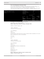
How to use the MegaCLI Command-Line Utility
Use a bootable DOS USB stick with XMS manager "himem.sys" and start the MegaCLI.exe.
Please see the command reference in MegaCLI Commandline Utility, page 47.
The whole amount of log events can be seen with MegaCLI –AdpAliLog –aAll > evt.txt; but it
takes a few minutes until the large file is written and it is too much information.
For example, it is much better, to use this commands
(create with "-f …txt" a file for analysis)
MegaCli -AdpEventLog -GetEvents -warning -f warning.txt -aALL
Adapter: 0 - Number of Events : 288
seqNum: 0x00001875
Time: Mon Jul 19 13:37:28 2010
Code: 0x00000124
Class: 1
Locale: 0x20
Event Description: Patrol Read can't be started, as PDs are either not ONLINE, or are in a VD
with an active process, or are in an excluded VD
Event Data:
===========
None
seqNum: 0x0000188b
Time: Mon Jul 19 13:52:41 2010
Code: 0x00000070
Class: 1
Locale: 0x02
Event Description: Removed: PD 06(e0xfc/s6)
Event Data:
===========
Device ID: 6
Enclosure Index: 252
Slot Number: 6
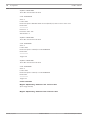
MegaCli -AdpEventLog -GetEvents -critical -f critical.txt -aALL
Adapter: 0 - Number of Events : 288
Bosch Sicherheitssysteme GmbH
Installation Manual
2014.01 | V2 | DOC
42
en | Appendix
DIVAR IP 6000 2U
seqNum: 0x00001893
Time: Mon Jul 19 13:52:41 2010
Code: 0x00000065
Class: 2
Locale: 0x02
Event Description: Rebuild failed on PD 04(e0xfc/s4) due to source drive error
Event Data:
===========
Device ID: 4
Enclosure Index: 252
Slot Number: 4
seqNum: 0x000018ba
Time: Mon Jul 19 14:12:25 2010
Code: 0x000000fb
Class: 2
Locale: 0x01
Event Description: VD 00/0 is now DEGRADED
Event Data:
===========
Target Id: 0
seqNum: 0x000018bc
Time: Mon Jul 19 14:12:25 2010
Code: 0x000000fb
Class: 2
Locale: 0x01
Event Description: VD 01/1 is now DEGRADED
Event Data:
===========
Target Id: 1
Useful commands:
MegaCli -AdpEventLog -GetEvents -info -f info.txt -aALL
(but a large text file)
MegaCli -AdpEventLog -GetEvents -fatal -f fatal.txt -aALL
2014.01 | V2 | DOC
Installation Manual
Bosch Sicherheitssysteme GmbH
DIVAR IP 6000 2U
Appendix | en
Adapter: 0 - Number of Events : 288
Adapter: 0 - Number of Events : 288
seqNum: 0x0000188f
seqNum: 0x00001891
Time: Mon Jul 19 13:52:41 2010
Time: Mon Jul 19 13:52:41 2010
Code: 0x000000fc
Code: 0x000000fc
Class: 3
Class: 3
Locale: 0x01
Locale: 0x01
Event Description: VD 00/0 is now OFFLINE
Event Description: VD 01/1 is now OFFLINE
Event Data:
Event Data:
===========
===========
Target Id: 0
Target Id: 1
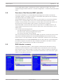
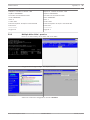
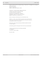
5.9.2
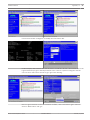
43
Multiple disks failed - practice
Press "C" to enter Utility. Click "start" and "scan disks".
You get to the "foreign configuration import" screen.
Select one of the two configurations and click Preview.
Bosch Sicherheitssysteme GmbH
Installation Manual
2014.01 | V2 | DOC
44
en | Appendix
DIVAR IP 6000 2U
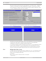
All disks are seen, but configuration is marked as not importable; click Cancel and view
Configuration 2. It is the same; this means, a complex situation requires manual interaction.
Click to clear all configurations, ignore the warning.
Before clear foreign configuration, 2 disks were missing, two were foreign. After clear, the
foreign disks now are shown as unconfigured.
2014.01 | V2 | DOC
Installation Manual
Bosch Sicherheitssysteme GmbH
DIVAR IP 6000 2U
Appendix | en
45
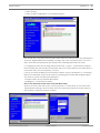
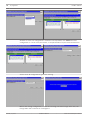
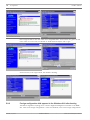
Use the event viewer or MegaCLI to identify the "first failed" disk.
In this example, disk in Slot 4 was first fail, Slot 7 second fail. Click on "second fail" PD7 in the
Logical View and you get in the Physical drive menu. Choose "replace missing PD" and the
correct row for Slot 7 drive and click "go". Ignore the warning.
Now in Logical View we see this disk marked as offline; click on the disk to get in PD menu.
Click on "Make online" and "go".
Bosch Sicherheitssysteme GmbH
Installation Manual
2014.01 | V2 | DOC
46
en | Appendix
DIVAR IP 6000 2U
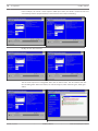
Now in logical view we see disk online and a degraded RAID. Click on disk 4 to get in the PD
menu. Click on correct row, on "Global" or "dedicated Hot Spare" and on "go".
Click on home; in the Logical View, the rebuild is starting.
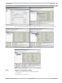
5.9.3
Foreign configuration disk appears in the Windows GUI after booting
The RAID is degraded. Topology error is shown. Right-click Megaraid Controller in the MSM
GUI. Click "scan foreign configuration". In the next window, click "clear foreign configuration".
2014.01 | V2 | DOC
Installation Manual
Bosch Sicherheitssysteme GmbH
DIVAR IP 6000 2U
Appendix | en
47
An unconfigured good drive is displayed. Right-click this drive and choose a hotspare type.
You see the rebuild is starting at once.
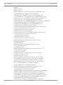
5.9.4
MegaCLI Commandline Utility
[-Silent] [-AppLogFile filename] [-NoLog] [-page [N]]
[-] is optional.
N - Number of lines per page.
Bosch Sicherheitssysteme GmbH
Installation Manual
2014.01 | V2 | DOC
48
en | Appendix
DIVAR IP 6000 2U
MegaCli -v
MegaCli -help|-h|?
MegaCli -adpCount
MegaCli -AdpSetProp {CacheFlushInterval -val} | { RebuildRate -val}
| {PatrolReadRate -val} | {BgiRate -val} | {CCRate -val}
| {ReconRate -val} | {SpinupDriveCount -val} | {SpinupDelay -val}
| {CoercionMode -val} | {ClusterEnable -val} | {PredFailPollInterval -val}
| {BatWarnDsbl -val} | {EccBucketSize -val} | {EccBucketLeakRate -val}
| {AbortCCOnError -val} | AlarmEnbl | AlarmDsbl | AlarmSilence
| {SMARTCpyBkEnbl -val} | {SSDSMARTCpyBkEnbl -val} | NCQEnbl | NCQDsbl
| {MaintainPdFailHistoryEnbl -val} | {RstrHotSpareOnInsert -val}
| {EnblSpinDownUnConfigDrvs -val} | {EnblSSDPatrolRead -val}
| {DisableOCR -val} | {BootWithPinnedCache -val}
| AutoEnhancedImportEnbl | AutoEnhancedImportDsbl -aN|-a0,1,2|-aALL
| {ExposeEnclDevicesEnbl -val} -aN|-a0,1,2|-aALL
| {DsblSpinDownHsp -val} -aN|-a0,1,2|-aALL
| {SpinDownTime -val} -aN|-a0,1,2|-aALL
MegaCli -AdpSetProp -AutoDetectBackPlaneDsbl -val -aN|-a0,1,2|-aALL
val - 0=Enable Auto Detect of SGPIO and i2c SEP.
1=Disable Auto Detect of SGPIO.
2=Disable Auto Detect of i2c SEP.
3=Disable Auto Detect of SGPIO and i2c SEP.
MegaCli -AdpSetProp -CopyBackDsbl -val -aN|-a0,1,2|-aALL
val - 0=Enable Copyback.
1=Disable Copyback.
MegaCli -AdpSetProp -EnableJBOD -val -aN|-a0,1,2|-aALL
val - 0=Disable JBOD mode.
1=Enable JBOD mode.
MegaCli -AdpSetProp -DsblCacheBypass -val -aN|-a0,1,2|-aALL
val - 0=Enable Cache Bypass.
1=Disable Cache Bypass.
MegaCli -AdpSetProp -LoadBalanceMode -val -aN|-a0,1,2|-aALL
val - 0=Auto Load balance mode.
1=Disable Load balance mode.
MegaCli -AdpSetProp -UseFDEOnlyEncrypt -val -aN|-a0,1,2|-aALL
val - 0=FDE and controller encryption (if HW supports) is allowed.
1=Only support FDE encryption, disallow controller encryption.
MegaCli -AdpSetProp -PrCorrectUncfgdAreas -val -aN|-a0,1,2|-aALL
val - 0= Correcting Media error during PR is disabled.
1=Correcting Media error during PR is allowed.
MegaCli -AdpSetProp -DsblSpinDownHSP -val -aN|-a0,1,2|-aALL
val - 0= Spinning down the Hot Spare is enabled.
1=Spinning down the Hot Spare is disabled.
MegaCli -AdpGetProp CacheFlushInterval | RebuildRate | PatrolReadRate
| BgiRate | CCRate | ReconRate | SpinupDriveCount | SpinupDelay
| CoercionMode | ClusterEnable | PredFailPollInterval | BatWarnDsbl
| EccBucketSize | EccBucketLeakRate | EccBucketCount | AbortCCOnError
| AlarmDsply | SMARTCpyBkEnbl | SSDSMARTCpyBkEnbl | NCQDsply
| MaintainPdFailHistoryEnbl | RstrHotSpareOnInsert
| EnblSpinDownUnConfigDrvs | EnblSSDPatrolRead | DisableOCR
2014.01 | V2 | DOC
Installation Manual
Bosch Sicherheitssysteme GmbH
Appendix | en
DIVAR IP 6000 2U
49
| BootWithPinnedCache | AutoEnhancedImportDsply | AutoDetectBackPlaneDsbl
| CopyBackDsbl | LoadBalanceMode | UseFDEOnlyEncrypt | WBSupport | EnableJBOD
| DsblCacheBypass | ExposeEnclDevicesEnbl | DsblSpinDownHsp | SpinDownTime
| PrCorrectUncfgdAreas -aN|-a0,1,2|-aALL
| DsblSpinDownHSP -aN|-a0,1,2|-aALL
MegaCli -AdpAllInfo -aN|-a0,1,2|-aALL
MegaCli -AdpGetTime -aN|-a0,1,2|-aALL
MegaCli -AdpSetTime yyyymmdd hh:mm:ss -aN
MegaCli -AdpSetVerify -f fileName -aN|-a0,1,2|-aALL
MegaCli -AdpBIOS -Enbl |-Dsbl | -SOE | -BE | -Dsply -aN|-a0,1,2|-aALL
MegaCli -AdpBootDrive {-Set {-Lx | -physdrv[E0:S0]}}|-Get -aN|-a0,1,2|-aALL
MegaCli -AdpAutoRbld -Enbl|-Dsbl|-Dsply -aN|-a0,1,2|-aALL
MegaCli -AdpCacheFlush -aN|-a0,1,2|-aALL
MegaCli -AdpPR -Dsbl|EnblAuto|EnblMan|Start|Stop|Info| SSDPatrolReadEnbl |
SSDPatrolReadDsbl
|{SetDelay Val}|{-SetStartTime yyyymmdd hh}|{maxConcurrentPD Val} -aN|-a0,1,2|-aALL
MegaCli -AdpCcSched -Dsbl|-Info|{-ModeConc | -ModeSeq [-ExcludeLD -LN|-L0,1,2]
[-SetStartTime yyyymmdd hh ] [-SetDelay val ] } -aN|-a0,1,2|-aALL
MegaCli -AdpCcSched -SetStartTime yyyymmdd hh -aN|-a0,1,2|-aALL
MegaCli -AdpCcSched -SetDelay val -aN|-a0,1,2|-aALL
MegaCli -FwTermLog -BBUoff|BBUoffTemp|BBUon|Dsply|Clear -aN|-a0,1,2|-aALL
MegaCli -AdpAlILog -aN|-a0,1,2|-aALL
MegaCli -AdpDiag [val] -aN|-a0,1,2|-aALL
val - Time in second.
MegaCli -AdpBatTest -aN|-a0,1,2|-aALL
MegaCli -PDList -aN|-a0,1,2|-aALL
MegaCli -PDGetNum -aN|-a0,1,2|-aALL
MegaCli -pdInfo -PhysDrv[E0:S0,E1:S1,...] -aN|-a0,1,2|-aALL
MegaCli -PDOnline -PhysDrv[E0:S0,E1:S1,...] -aN|-a0,1,2|-aALL
MegaCli -PDOffline -PhysDrv[E0:S0,E1:S1,...] -aN|-a0,1,2|-aALL
MegaCli -PDMakeGood -PhysDrv[E0:S0,E1:S1,...] | [-Force] -aN|-a0,1,2|-aALL
MegaCli -PDMakeJBOD -PhysDrv[E0:S0,E1:S1,...] -aN|-a0,1,2|-aALL
MegaCli -PDHSP {-Set [-Dedicated [-ArrayN|-Array0,1,2...]] [-EnclAffinity] [-nonRevertible]}
|-Rmv -PhysDrv[E0:S0,E1:S1,...] -aN|-a0,1,2|-aALL
MegaCli -PDRbld -Start|-Stop|-ShowProg |-ProgDsply
-PhysDrv [E0:S0,E1:S1,...] -aN|-a0,1,2|-aALL
MegaCli -PDClear -Start|-Stop|-ShowProg |-ProgDsply
-PhysDrv [E0:S0,E1:S1,...] -aN|-a0,1,2|-aALL
MegaCli -PdLocate {[-Start] | -stop } -physdrv[E0:S0,E1:S1,...] -aN|-a0,1,2|-aALL
MegaCli -PdMarkMissing -physdrv[E0:S0,E1:S1,...] -aN|-a0,1,2|-aALL
MegaCli -PdGetMissing -aN|-a0,1,2|-aALL
MegaCli -PdReplaceMissing -physdrv[E0:S0] -arrayA, -rowB -aN
MegaCli -PdPrpRmv [-UnDo] -physdrv[E0:S0] -aN|-a0,1,2|-aALL
MegaCli -EncInfo -aN|-a0,1,2|-aALL
MegaCli -EncStatus -aN|-a0,1,2|-aALL
MegaCli -PhyInfo -phyM -aN|-a0,1,2|-aALL
MegaCli -LDInfo -Lx|-L0,1,2|-Lall -aN|-a0,1,2|-aALL
MegaCli -LDSetProp {-Name LdNamestring} | -RW|RO|Blocked | WT|WB [-Immediate]|RA|NORA|
ADRA
| Cached|Direct | -EnDskCache|DisDskCache | CachedBadBBU|NoCachedBadBBU
Bosch Sicherheitssysteme GmbH
Installation Manual
2014.01 | V2 | DOC
50
en | Appendix
DIVAR IP 6000 2U
-Lx|-L0,1,2|-Lall -aN|-a0,1,2|-aALL
MegaCli -LDGetProp -Cache | -Access | -Name | -DskCache -Lx|-L0,1,2|-LALL
-aN|-a0,1,2|-aALL
MegaCli -getLdExpansionInfo -Lx|-L0,1,2|-Lall -aN|-a0,1,2|-aALL
MegaCli -LdExpansion -pN -dontExpandArray -Lx|-L0,1,2|-Lall -aN|-a0,1,2|-aALL
MegaCli -LDInit {-Start [-full]}|-Abort|-ShowProg|-ProgDsply -Lx|-L0,1,2|-LALL -aN|-a0,1,2|-aALL
MegaCli -LDCC {-Start [-force]}|-Abort|-ShowProg|-ProgDsply -Lx|-L0,1,2|-LALL -aN|-a0,1,2|aALL
MegaCli -LDBI -Enbl|-Dsbl|-getSetting|-Abort|-ShowProg|-ProgDsply -Lx|-L0,1,2|-LALL -aN|a0,1,2|-aALL
MegaCli -LDRecon {-Start -rX [{-Add | -Rmv} -Physdrv[E0:S0,...]]}|-ShowProg|-ProgDsply
-Lx -aN
MegaCli -LdPdInfo -aN|-a0,1,2|-aALL
MegaCli -LDGetNum -aN|-a0,1,2|-aALL
MegaCli -LDBBMClr -Lx|-L0,1,2,...|-Lall -aN|-a0,1,2|-aALL
MegaCli -CfgLdAdd -rX[E0:S0,E1:S1,...] [WT|WB] [NORA|RA|ADRA] [Direct|Cached]
[CachedBadBBU|NoCachedBadBBU] [-szXXX [-szYYY ...]]
[-strpszM] [-Hsp[E0:S0,...]] [-AfterLdX] [-Force]|[FDE|CtrlBased] -aN
MegaCli -CfgSscdAdd -Physdrv[E0:S0,...] {-Name LdNamestring} -aN|-a0,1,2|-aALL
MegaCli -CfgEachDskRaid0 [WT|WB] [NORA|RA|ADRA] [Direct|Cached]
[CachedBadBBU|NoCachedBadBBU] [-strpszM]|[FDE|CtrlBased] -aN|-a0,1,2|-aALL
MegaCli -CfgClr -aN|-a0,1,2|-aALL
MegaCli -CfgDsply -aN|-a0,1,2|-aALL
MegaCli -CfgLdDel -LX|-L0,2,5...|-LALL -aN|-a0,1,2|-aALL
MegaCli -CfgSscdDel -LX|-L0,2,5...|-LALL -aN|-a0,1,2|-aALL
MegaCli -CfgFreeSpaceinfo -aN|-a0,1,2|-aALL
MegaCli -CfgSpanAdd -r10 -Array0[E0:S0,E1:S1] -Array1[E0:S0,E1:S1] [ArrayX[E0:S0,E1:S1] ...] -aN
MegaCli -CfgSpanAdd -r50 -Array0[E0:S0,E1:S1,E2:S2,...] -Array1[E0:S0,E1:S1,E2:S2,...]
[-ArrayX[E0:S0,E1:S1,E2:S2,...] ...] [WT|WB] [NORA|RA|ADRA] [Direct|Cached]
[CachedBadBBU|NoCachedBadBBU][-strpszM][-szXXX[-szYYY ...]][-AfterLdX]|
[FDE|CtrlBased] -aN
MegaCli -CfgAllFreeDrv -rX [-SATAOnly] [-SpanCount XXX] [WT|WB] [NORA|RA|ADRA]
[Direct|Cached] [CachedBadBBU|NoCachedBadBBU] [-strpszM]
[-HspCount XX [-HspType -Dedicated|-EnclAffinity|-nonRevertible]] |
[FDE|CtrlBased] -aN
MegaCli -CfgSave -f filename -aN
MegaCli -CfgRestore -f filename -aN
MegaCli -CfgForeign -Scan | [-SecurityKey sssssssssss] -aN|-a0,1,2|-aALL
MegaCli -CfgForeign -Dsply [x] | [-SecurityKey sssssssssss] -aN|-a0,1,2|-aALL
MegaCli -CfgForeign -Preview [x] | [-SecurityKey sssssssssss] -aN|-a0,1,2|-aALL
MegaCli -CfgForeign -Import [x] | [-SecurityKey sssssssssss] -aN|-a0,1,2|-aALL
MegaCli -CfgForeign -Clear [x]|[-SecurityKey sssssssssss] -aN|-a0,1,2|-aALL
x - index of foreign configurations. Optional. All by default.
MegaCli -AdpEventLog -GetEventLogInfo -aN|-a0,1,2|-aALL
MegaCli -AdpEventLog -GetEvents {-info -warning -critical -fatal} {-f <fileName>} -aN|-a0,1,2|aALL
MegaCli -AdpEventLog -GetSinceShutdown {-info -warning -critical -fatal} {-f <fileName>} -aN|a0,1,2|-aALL
2014.01 | V2 | DOC
Installation Manual
Bosch Sicherheitssysteme GmbH
Appendix | en
DIVAR IP 6000 2U
51
MegaCli -AdpEventLog -GetSinceReboot {-info -warning -critical -fatal} {-f <fileName>} -aN|a0,1,2|-aALL
MegaCli -AdpEventLog -IncludeDeleted {-info -warning -critical -fatal} {-f <fileName>} -aN|a0,1,2|-aALL
MegaCli -AdpEventLog -GetLatest n {-info -warning -critical -fatal} {-f <fileName>} -aN|-a0,1,2|aALL
MegaCli -AdpEventLog -GetCCIncon -f <fileName> -LX|-L0,2,5...|-LALL -aN|-a0,1,2|-aALL
MegaCli -AdpEventLog -Clear -aN|-a0,1,2|-aALL
MegaCli -AdpBbuCmd -aN|-a0,1,2|-aALL
MegaCli -AdpBbuCmd -GetBbuStatus -aN|-a0,1,2|-aALL
MegaCli -AdpBbuCmd -GetBbuCapacityInfo -aN|-a0,1,2|-aALL
MegaCli -AdpBbuCmd -GetBbuDesignInfo -aN|-a0,1,2|-aALL
MegaCli -AdpBbuCmd -GetBbuProperties -aN|-a0,1,2|-aALL
MegaCli -AdpBbuCmd -BbuLearn -aN|-a0,1,2|-aALL
MegaCli -AdpBbuCmd -BbuMfgSleep -aN|-a0,1,2|-aALL
MegaCli -AdpBbuCmd -BbuMfgSeal -aN|-a0,1,2|-aALL
MegaCli -AdpBbuCmd -SetBbuProperties -f <fileName> -aN|-a0,1,2|-aALL
MegaCli -AdpFacDefSet -aN
MegaCli -AdpM0Flash -f filename
MegaCli -AdpGetConnectorMode -ConnectorN|-Connector0,1|-ConnectorAll -aN|-a0,1,2|-aALL
MegaCli -AdpSetConnectorMode -Internal|-External|-Auto -ConnectorN|-Connector0,1|ConnectorAll -aN|-a0,1,2|-aALL
MegaCli -PhyErrorCounters -aN|-a0,1,2|-aALL
MegaCli -DirectPdMapping -Enbl|-Dsbl|-Dsply -aN|-a0,1,2|-aALL
MegaCli -ShowEnclList -aN|-a0,1,2|-aALL
MegaCli -ShowVpd -Page N -Encl N -aN|-a0,1,2|-aALL
MegaCli -EnclLocate -Start|-Stop -Encl N -aN|-a0,1,2|-aALL
MegaCli -EnclFwDownload -Encl N -Esm A|B -f <filename> -aN|-a0,1,2|-aALL
MegaCli -PdFwDownload [-SataBridge] -PhysDrv[0:1,1:2,...] -f <filename> -aN|-a0,1,2|-aALL
MegaCli -SetFacDefault -Encl N -Esm A|B -f <filename> -aN|-a0,1,2|-aALL
MegaCli -PDCpyBk -Start -PhysDrv[E0:S0,E1:S1] -aN|-a0,1,2|-aALL
MegaCli -PDCpyBk -Stop|-ShowProg|-ProgDsply -PhysDrv[E0:S0] -aN|-a0,1,2|-aALL
MegaCli -PDInstantSecureErase -PhysDrv[E0:S0,E1:S1,...] | [-Force] -aN|-a0,1,2|-aALL
MegaCli -LDMakeSecure -Lx|-L0,1,2,...|-Lall -aN|-a0,1,2|-aALL
MegaCli -DestroySecurityKey | [-Force] -aN
MegaCli -CreateSecurityKey -SecurityKey sssssssssss | [-Passphrase sssssssssss] |[-KeyID
kkkkkkkkkkk] -aN
MegaCli -ChangeSecurityKey -OldSecurityKey sssssssssss | -SecurityKey sssssssssss|
[-Passphrase sssssssssss] | [-KeyID kkkkkkkkkkk] -aN
MegaCli -GetKeyID [-PhysDrv[E0:S0]] -aN
MegaCli -SetKeyID -KeyID kkkkkkkkkkk -aN
MegaCli -VerifySecurityKey -SecurityKey sssssssssss -aN
sssssssssss - It must be between eight and thirty-two
characters and contain at least one number,
one lowercase letter, one uppercase
letter and one non-alphanumeric character.
kkkkkkkkkkk - Must be less than 256 characters.
MegaCli -GetPreservedCacheList -aN|-a0,1,2|-aALL
MegaCli -DiscardPreservedCache -Lx|-L0,1,2|-Lall -aN|-a0,1,2|-aALL
Bosch Sicherheitssysteme GmbH
Installation Manual
2014.01 | V2 | DOC
52
en | Appendix
DIVAR IP 6000 2U
MegaCli -AdpInfoCompare {-checkFw <string> | -checkID -hex | -checkBatt -val | -checkDimm val} -aN|-a0,1,2|-aALL
MegaCli -adpFwDump
MegaCli -AdpNameRtn -aN|-a0,1,2|-aALL
sssssssssss - It must be between eight and thirty-two
characters and contain at least one number,
one lowercase letter, one uppercase
letter and one non-alphanumeric character.
kkkkkkkkkkk - Must be less than 256 characters.
MegaCli -ShowSummary [-f filename] -aN
Note: The directly connected drives can be specified as [:S]
Wildcard '?' can be used to specify the enclosure ID for the drive in the
only enclosure without direct connected device or the direct connected
drives with no enclosure in the system.
Note:[-aALL] option assumes that the parameters specified are valid
for all the Adapters.
The following options may be given at the end of any command above:
[-Silent] [-AppLogFile filename] [-NoLog] [-page [N]]
[-] is optional.
N - Number of lines per page.
Exit Code: 0x00
2014.01 | V2 | DOC
Installation Manual
Bosch Sicherheitssysteme GmbH
Bosch Sicherheitssysteme GmbH
Robert-Bosch-Ring 5
85630 Grasbrunn
Germany
www.boschsecurity.com
© Bosch Sicherheitssysteme GmbH, 2014