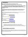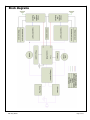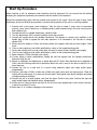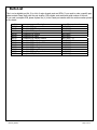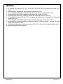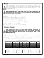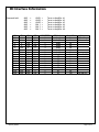
1
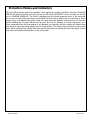
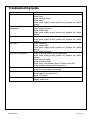
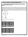
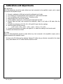
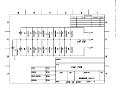
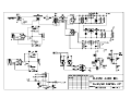
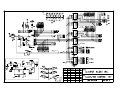
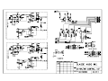
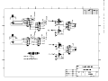
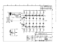
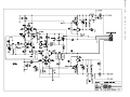
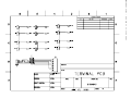
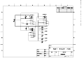
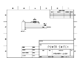
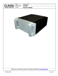
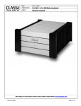
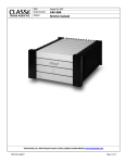
Classé Audio Inc.
Date:
July 17, 2007
Model Number:
CA-401
Subject:
Service manual
Classé Audio, Inc. 5070 François Cusson Lachine, Québec Canada H8T1B3, www.classeaudio.com
PRO-SVR_LEGACY
Page 1 of 13
Table of Contents
Introduction 3
Important Notes on Servicing 3
Ordering Replacement Parts 3
Block Diagrams 4
Start up Procedure 5
Protection Modes and Indicators 6
Troubleshooting Guide 7
Output Transistors Testing and Replacement 8
Calibrations and Adjustments 19
Parts List 10
Updates 11
Fuses 12
Voltage Change 12
IR Interface Information 13
Schematics 14
The contents of this document as well as the files associated with it contain confidential information that is proprietary to Classé Audio
Incorporated and are intended solely for the purpose of servicing product. No part of its contents may be used, copied, disclosed, or conveyed to
any party in any manner whatsoever without prior written permission from Classé Audio Incorporated.
PRO-SVR_LEGACY
Page 2 of 13
Introduction
Please read this manual carefully before commencing servicing!
Only qualified and authorized personnel should attempt to service this product.
The lightning flash with arrowhead symbol, within an equilateral triangle, is intended
to alert the user to the presence of uninsulated dangerous voltage within the
product’s enclosure that may be of sufficient magnitude to constitute a risk of electric
shock to persons.
The exclamation point within an equilateral triangle is intended to alert the user to
the presence of important operating and maintenance (servicing) instructions.
Classé has a global product support network. For product assistance or to order replacement parts please
contact your nearest service center always quoting the unit serial number.
North America
Phone: (978) 664-2870 E-mail: [email protected]
Europe
Phone: 44 (0) 1903 221 700 E-mail: [email protected]
Asia
Phone: (852) 2790 8903 E-mail: [email protected]
Rest of the World
Phone: (514) 636-6384 E-mail: [email protected]
Important Notes on Servicing
1. ALWAYS observe ESD precautions when handling electronic modules or PCBAs.
2. NEVER exchange boards with a different revision number, unless authorized by Classé.
3. ALWAYS use Classé original replacement parts. The use of generic parts may void the warranty of
the unit.
Ordering Replacement Parts
There may be a delay in processing incomplete requests. Please be sure to include all required information.
Remember to quote the serial number of the unit on all replacement part orders and the Classé order number
when returning defective parts for credit.
PRO-SVR_LEGACY
Page 3 of 13
Block diagrams
PRO-SVR_LEGACY
Page 4 of 13
Start Up Procedure
When receiving a unit, an assiduous visual inspection must be performed. Do not connect the unit without
analysing the symptoms reported by the customer and the results of the inspection.
Using the troubleshooting guide, find the problem and proceed to the repair. Once this step is done, follow
these steps, known as the start-up procedure, to ensure that everything in the unit is in working condition.
1. Proceed with a post repair visual inspection. Take the time to check if every wire is reconnected
properly, every screw is bolted on, no soldering and/or metal residues lying in the unit, every fuse has
been replaced, etc.
2. Connect the unit to a variable transformer, setted to 0Vac.
3. Turn the bias trimpot (RV1) counter clockwise until a click is heard.
4. Connect the bypass wire to the variable transformer. This bypass is a power cord, modified on the
female side in order to bypass the soft start sequence. It is connected to the line tab on voltage
selector PCB.
5. Slowly raise the voltage to 10Vac, and check positive and negative rails and pre-driver supply. Check
fuses.
6. If one or more supply are not within specifications, return to the troubleshooting guide.
7. Slowly raise voltage until you hear relays click, this point is around 55Vac. Recheck every supply.
8. If one or more supply are not within specifications, return to the troubleshooting guide.
9. Raise voltage to 120Vac. Recheck every supply
10. If every supply is within specifications, unplug the unit and bypass from the variable transformer.
Reconnect only the unit.
11. Report to calibration and adjusments to adjust bias and DC offset. Note that bias can be adjusted to
14mV, and the following tests can be performed before the unit is send to the burn-in bench for a 24
hours warm-up.
12. Connect the unit to a load, and to a source using balanced inputs and single ended inputs,
independently.
13. Perform a test with a 200Hz, a 2kHz and a 20kHz tone, both sinus wave and square wave. Check the
output with a oscilloscope, on 4 ohms and 8 ohms loads. Take special cares about oscillation and phase
correlation between channels.
14. Connect the unit to a small speaker, and short the input. Check for any noise. Perform this step with
single ended inputs and balanced inputs, independently.
15. Put the unit on a burn-in bench, and let it sit for 24 hours, then readjust bias. Let the unit on the burnin bench for another 72 hours.
16. Redo steps 11 to 14 before shipping to the customer.
PRO-SVR_LEGACY
Page 5 of 13
Protection Modes and Indicators
The front LED shows the status of the amplifier. When starting up normally, the CA401 will show a FLASHING
RED LED for about 15 seconds and if all is normal, the LED will go SOLID RED. If there is a fault, the LED will
go to a FLASHING GREEN LED. The CA401 is equipped with four Mosfet protection fuses. In the event that
one or more of these fuses would blow, the technician will first need to identify and cure the cause of failure
(please report to troubleshooting guide). When the cause has been identified, disconnect the unit from the
system including the AC power. Remove the top cover and look for damaged or burned components. If no
other components than the fuses appear to be damaged, the technician can then replace the broken fuses
with the same value and rating (please report to fuses section). The Mosfet fuses are located on the control
board. When replacing fuses, please make sure that the fuse holder are holding the fuses very tightly. A loose
fuse holder can translate into distortion on top of the signal.
PRO-SVR_LEGACY
Page 6 of 13
Troubleshooting Guide
Symptom
Unit won’t turn on
Smoked and/or burned
components
Blown fuses
No output
Unit turn into protection
Excessive buzz and/or hum
Oscillation
Intermittent signal
PRO-SVR_LEGACY
Possible cause
Check connections;
Check fuses;
Check soft-start circuit;
Check relays;
Check power supply circuits (positive rail, negative rail,
supply).
Check for short between components and ground;
Check output transistors;
Check output relays;
Check power supply circuits (positive rail, negative rail,
supply).
Check for short between fuse and ground;
Check power supply circuits (positive rail, negative rail,
supply).
Check connexions;
Check output relays;
Check power supply circuits (positive rail, negative rail,
supply);
Check output transistors.
Check for smoked and/or burned components;
Check power supply circuits (positive rail, negative rail,
supply);
Check source and load;
Check protection circuit;
Check sensor wires between sensor PCB and control PCB;
Check outputs transistors and Mosfet drivers.
Check electrical lines;
Check for a ground loop in the system.
Check source;
Check capacitors on main board;
Check 4.7ƻ resistor.
Check connections;
Replace shield wires.
Mosfet
Mosfet
Mosfet
Mosfet
Mosfet
Page 7 of 13
Output Transistors Testing and Replacement
PLEASE NOTE THAT THESE TESTS ARE ONLY EFFECTIVE ON BIPOLAR TRANSISTORS.
DO NOT PERFORM THESE TESTS ON MOSFET DEVICES, AS THEY ARE LIKELY TO
BECOME SHORT DURING THE TEST.
You should check all pin combinaisons, as there is a chance that only one side of the transistor is short. When
replacing outputs transistors, the technician should first disconnect both outputs and main board to check if
the blown outputs were caused by a faulty component on the amplifier’s base. Blown output transistors should
be replaced by kits, not individually. These kits contains matched transistors for both rails of one channel.
When replacing blown output transistors, you must also replace positive and negative Mosfet drivers and bias
transistor. Carefully inspect 4.7ƻ resistor and 10ƻ soft start resistor, and replace if necessary. Replace any
burnt component or board.
Pins : 1
2
Case
Base
Emitter
Collector
You should have these results, if the transistor is good.
MJ21194 (NPN)
Positive lead
B
B
C
C
E
E
Negative lead
C
E
B
E
B
C
Result
Conductive
Conductive
Infinite
Infinite
Infinite
Infinite
Negative lead
C
E
B
E
B
C
Result
Infinite
Infinite
Conductive
Infinite
Conductive
Infinite
MJ21193 (PNP)
Positive lead
B
B
C
C
E
E
PRO-SVR_LEGACY
Page 8 of 13
Calibrations and Adjustments
Bias adjustment:
Note: Bias adjustment should be made without any load connected to the amplifier’s output, and no signal
connected to the amplifier’s input.
1.
2.
3.
4.
5.
6.
Connect a multimeter to R8 leads and set the multimeter to mV scale.
Turn trimpot RV1 counterclockwise until it reaches 0ƻ. A click should be heard.
Turn on amplifier, and let it warm up for 15 minutes on idle.
Adjust trimpot RV1 to get a 14mV reading.
Let the amplifier warm up for a 24 hours period with signal and load.
Remove signal and load, and reconnect the multimeter, setted to mV scale, to R8 leads. Note the
reading.
7. Connect the multimeter to R9, R10, R11, R12 and R13 leads. Note the readings.
8. Input the results into this formula:
((144 – mVR8 – mVR9 – mVR10 – mVR11 – mVR12 – mVR13) ÷ 6) + mVR8
9. Connect the multimeter to R8 leads, and adjust RV1 to match the reading to the formula result.
10. Results should be around 24mV.
DC offset:
Note: DC offset adjustment should be made without any load connected to the amplifier’s output, and no
signal connected to the amplifier’s input.
On these units, DC offset can’t be adjusted. Measure DC offset using a voltmeter connected to the output
posts, scale setted to mV. DC offset should be less than 10mV.
PRO-SVR_LEGACY
Page 9 of 13
Parts List
This is not a detailed part list. It is a list of major chassis parts and PCBs. If you need to order a specific part,
please contact Classe Audio with the part location, PCB number, and model and serial number of the unit.
If you need a complete PCB, please replace the (x) in the Classe part number with the revision number printed
on the board.
Parts
B1DAX
B01GX
B012X
B013X
B015X
B017X
B017X
B018X
B019X
B1D8X
B02AX
B1D6X
B20BX
PRO-SVR_LEGACY
Complete
Complete
Complete
Complete
Complete
Complete
Complete
Complete
Complete
Complete
Complete
Complete
Complete
PCB,
PCB,
PCB,
PCB,
PCB,
PCB,
PCB,
PCB,
PCB,
PCB,
PCB,
PCB,
PCB,
Description
power switch
filter
capacitor
control
input
output, bottom
output, top
output, middle
sensor
soft start
amplifier
voltage selector
IR sensor
Classe part number
B1DAXR(x)
B01GXR(x)
B012XR(x)
B013XR(x)
B015XR(x)
B017XR(x) – B
B017XR(x) – T
B018XR(x)
B019XR(x)
B1D8XR(x)
B02AXR(x)
B1D6XR(x)
B20BXR(x)
Page 10 of 13
Updates
1. On board B015X, replace R101, R103, R105, R201, R203 and R205 with Classe part number A2111308.
2. On board B013X, replace R108 with Classe part number A211-1344
3. On board B02AX (both PCBs), replace R140 and R141 with Classe part number A211-1458
4. On board B017X (both PCBs), replace RV1 with Classe part number A214-1003
5. On board B018X (both PCBs), replace R5 and R6 with Classe part number A205-1016
6. On board B02AX, check C115 and C117 for damage and replace them if necessary with Classe part
number A201-1162
7. On board B012X, remove brackets and install 4 stand off, Classe part number A307-1089
8. On board B013X, replace PO11XR02 program with 040AR3, Classe part number and drop rail sensor
voltage from 500mV to 275mV
9. On chassis, install capacitors Classe part number A201-1162 on AC poles of the bridge rectifiers (both)
10. Replace shield wires with newer type.
PRO-SVR_LEGACY
Page 11 of 13
Fuses
EXTRA PRECAUTIONS SHOULD BE TAKEN WHEN REPAIRING, MODIFYING, OR
TROUBLESHOOTING IN THE POWER SUPPLY AREA. UNIT MUST BE DISCONNECT
FROM MAIN SOURCE AND CAPACITORS MUST BE DISCHARGED USING A 100W
INCANDESCENT BULB.
WHEN REPLACING FUSES, PLEASE MAKE SURE THAT THE FUSE HOLDERS ARE
HOLDING THE FUSES VERY TIGHTLY. A LOOSE FUSE HOLDER CAN TRANSLATE INTO
DISTORTION ON TOP OF THE SIGNAL.
Main fuses:
For 100 – 120v units: 15A slo-blo, Classe part number MDA-15A
For 220 – 240v units: 12A slo-blo, Classe part number MDA-12A
The main fuse is located at the back of the unit, on the rear panel.
Control board fuse: 0.50A, Classe part number 225.500
The control board fuse is located on top of the control board (B013X)
Mosfet fuses: 0.75A, Classe part number 225.750
The Mosfet fuses are located on top of the control board (B013X)
Voltage Change
EXTRA PRECAUTIONS SHOULD BE TAKEN WHEN REPAIRING, MODIFYING, OR
TROUBLESHOOTING IN THE POWER SUPPLY AREA. UNIT MUST BE DISCONNECT
FROM MAIN SOURCE AND CAPACITORS MUST BE DISCHARGED USING A 100W
INCANDESCENT BULB.
1. Set the primary wires of the main transformer as described below.
2. Replace the varistor, according to new line voltage, following Classe’s recommendations. If varistor is
not available, remove old varistor and leave it empty.
3. Set the jumpers accordingly on the auxiliary transformer located at the back of the unit on the top
main board on the left-hand side of the auxiliary transformer (see tables below)
Mains
Z1
Z2
100VAC
120VAC
220VAC
240VAC
Blue
Gray
Gray
Gray
Black
Yellow
Black
Yellow
Mains
100/120VAC
220/240VAC
PRO-SVR_LEGACY
Position 1
In
Out
Primary wires, main transformer
Z3
Z4
Z5
Z6
White
White
White
White
Orange
Orange
-
Blue
Blue
Orange
Orange
Jumpers, auxiliary transformer
Position 2
Position 3
Out
Out
Out
In
Z7
Z8
Gray
Blue
-
Yellow
Black
Yellow
Black
Position 4
Out
Out
Varist
or
140
140
250
250
Position 5
In
Out
Page 12 of 13
IR Interface Information
Press and hold:
J3
X
X
X
X
X
X
X
X
Out
Out
Out
Out
Out
Out
Out
Out
PRO-SVR_LEGACY
AMP
AMP
AMP
AMP
AMP
AMP
J2
X
X
X
X
Out
Out
Out
Out
X
X
X
X
Out
Out
Out
Out
J1
X
X
Out
Out
X
X
Out
Ot
X
X
Out
Out
X
X
Out
Out
+
+
+
+
+
+
LINE 1
LINE 2
LINE 3
BAL 1
BAL 2
BAL 3
J0
X
Out
X
Out
X
Out
X
Out
X
Out
X
Out
X
Out
X
Out
=
=
=
=
=
=
Turns
Turns
Turns
Turns
Turns
Turns
ADDRESS
0
1
2
3
4
5
0
0
0
1
2
3
4
5
0
0
on
on
on
on
on
on
Amplifier
Amplifier
Amplifier
Amplifier
Amplifier
Amplifier
#
#
#
#
#
#
RC Button
Amp1
Amp2
Amp3
Amp4
Amp5
Amp6
Amp1
Amp1
DC
DC
DC
DC
DC
DC
DC
DC
1
2
3
4
5
6
Auto ON
No
No
No
No
No
No
No
Yes
No
No
No
No
No
No
No
Yes
Note
QC setting
On with AC
On with AC
Page 13 of 13
B012XR03.sch-1 - Tue Jul 17 11:42:43 2007
B015XR06.sch-1 - Tue Jul 17 11:43:10 2007
B017XR05_B018XR04.sch-1 - Tue Jul 17 11:43:35 2007
B019XR02.sch-1 - Tue Jul 17 11:35:07 2007
B01GXR02.sch-1 - Tue Jul 17 11:41:29 2007
B02AXR01.sch-1 - Tue Jul 17 11:35:49 2007
B1D6XR01.sch-1 - Tue Jul 17 11:36:18 2007
B1D8XR00.sch-1 - Tue Jul 17 11:36:43 2007
B20BXR00.sch-1 - Tue Jul 17 11:42:04 2007