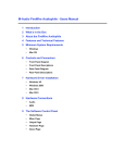
1
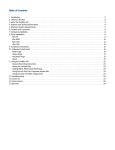
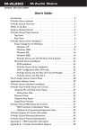
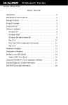
TAMPA Manual
version: Tampa-081602
Table of Contents
Introduction . . . . . . . . . . . . . . . . . . . . . . . . . . . . . . . . . . . . . . . . . . . . .2
Temporal Harmonic Alignment . . . . . . . . . . . . . . . . . . . . . . . . . . .2
Dual Optical Servo Compressor . . . . . . . . . . . . . . . . . . . . . . . . . .2
Your TAMPA’s Features . . . . . . . . . . . . . . . . . . . . . . . . . . . . . . . . . . . . .2
Front and Rear Panel Descriptions . . . . . . . . . . . . . . . . . . . . . . . . . . . .3
Front Panel Features . . . . . . . . . . . . . . . . . . . . . . . . . . . . . . . . . . .3
Rear Panel Features . . . . . . . . . . . . . . . . . . . . . . . . . . . . . . . . . . . .5
Setup and Connection . . . . . . . . . . . . . . . . . . . . . . . . . . . . . . . . . . . . .5
AC power . . . . . . . . . . . . . . . . . . . . . . . . . . . . . . . . . . . . . . . . . . .5
Connecting Your Tampa’s Outputs . . . . . . . . . . . . . . . . . . . . . . . . .6
Power-Up Procedure . . . . . . . . . . . . . . . . . . . . . . . . . . . . . . . . . . .8
Connecting To Your Tampa’s Inputs . . . . . . . . . . . . . . . . . . . . . . . .8
TAMPA Controls . . . . . . . . . . . . . . . . . . . . . . . . . . . . . . . . . . . . . . . . .9
Setting Levels . . . . . . . . . . . . . . . . . . . . . . . . . . . . . . . . . . . . . . . . .9
The Input Impedance Selector . . . . . . . . . . . . . . . . . . . . . . . . . . .11
Using the Phase Invert Switch . . . . . . . . . . . . . . . . . . . . . . . . . . .11
Using the Low-Cut Filter . . . . . . . . . . . . . . . . . . . . . . . . . . . . . . .11
Setting the Compressor . . . . . . . . . . . . . . . . . . . . . . . . . . . . . . . .12
TAMPA Specifications . . . . . . . . . . . . . . . . . . . . . . . . . . . . . . . . . . . . .16
Preamp Specs . . . . . . . . . . . . . . . . . . . . . . . . . . . . . . . . . . . . . . .16
Analog Compressor Specs . . . . . . . . . . . . . . . . . . . . . . . . . . . . . .16
Technical Support & Contact Information . . . . . . . . . . . . . . . . . . . . . .17
Your TAMPA’s Warranty . . . . . . . . . . . . . . . . . . . . . . . . . . . . . . . . . . .18
Introduction
Congratulations on your purchase of the TAMPA, designed and
manufactured by M-Audio. TAMPA is a professional, single channel
microphone/instrument preamp unlike any other.That’s because our design
team set out to discover just why expensive tube technology sounds so
good, and devise a way to land that sound at affordable solid state prices.
The result is far beyond tube modeling. It’s a whole new technology called
Temporal Harmonic Alignment™.
• Balanced/unbalanced TRS instrument input
• 24-bit digital S/PDIF and AES/EBU output for direct connection to your
digital recording gear
• 20dB gain switch for an amazing maximum system gain of 66dB
• 20dB passive output pad switch
• Low-cut switch to eliminate rumble
• Discrete, class A circuitry throughout
• VU-style meters for output level and compression gain reduction
• Clip indicator
Temporal Harmonic Alignment
Front and Rear Panel Descriptions
—the Secret Behind the Sound: In natural sound sources such as strings,
drum heads and vocal chords, harmonics share a characteristic temporal
(phase) relationship to the fundamental. Our ears exhibit the same
qualities. Solid state electronics induce distortion in the form of additional
harmonics that are out of phase with the original source. Tube-based
devices strike the ear as having such a “warm” sound because the added
harmonics have the same temporal relationship as natural mechanisms
(although predominantly in the midrange).This results in a sweet spot that
makes vocals, guitars and other midrange-rich content sound especially
pleasing. TAMPA’s revolutionary new Temporal Harmonic Alignment
technology produces that same phase relationship found in both tubes and
nature. And unlike tubes, TAMPA’s sweet spot spans the full spectrum of
your sound—from bass to cymbals.
Figure 1 - TAMPA Front Panel Features
Front Panel Features
• Professional mic/instrument preamp with Temporal Harmonic Alignment
• Built-in dual optical servo compressor
• Balanced phantom-powered XLR mic input with variable impedance for
optimized performance with vintage mics
1. POWER:Turns master power on/off for the unit.
2. +48V: Provides 48-volt phantom power to the XLR microphone input
when engaged. Switch to the ON position when using a microphone
requiring phantom power.
3. +48V INDICATOR: Lights when +48V switch is engaged to indicate that
phantom power is on.
4. MICROPHONE/INSTRUMENT: Neutrix connector accepts both an XLR
microphone input and a 1/4” TRS balanced or TS unbalanced instrument input.
5. INST/MIC: Switches between instrument and microphone inputs. Set to
“INST” when using the 1/4” input jack, and set to “MIC” when using the
XLR input jack.When INST is selected, the XLR input is disabled, and when
MIC is selected, the 1/4” input is disabled.
6. INPUT IMPEDANCE: Allows user to select input impedances of 2400
ohms, 1200 ohms, 600 ohms or 300 ohms. This is particularly useful in
conjunction with vintage mics requiring one of these impedances. For many
modern mics, the recommended setting is 2400 ohms, though the load
impedance setting is much more critical for vintage mics.
7. GAIN: Master preamp gain where fully counterclockwise yields minimum
gain (0db) and fully clockwise delivers maximum gain (34dB).
8. +20dB: Provides an additional 20dB of preamp gain when engaged.
2
3
Dual Optical Servo Compressor
TAMPA also includes a dual optical servo compressor that is worth the
price alone. Three fundamental problems plague engineers in designing
compressors—distortion, noise and accuracy.The VCA technology used in
inexpensive compressors exhibits less than professional specs on all three
counts. Simple optical servo technology is much more quiet and accurate,
yet has its own issues with distortion. The dual optical servo technology
we use in TAMPA yields low noise, consistent accuracy, low distortion and
exceptional transparency—and it comes built-in to a great mic preamp.
Your TAMPA’s Features
9. LOW CUT: Rolls off 12dB per octave at 80Hz and below when engaged.
Use this to avoid rumble from passing traffic, footsteps and so forth.
10. COMPRESSOR IN/OUT: Engages/disengages the TAMPA’s entire
compressor stage. When disengaged, TAMPA’s compressor circuitry is
removed from the signal path.
11. COMPRESSOR IN/OUT INDICATOR: Lights when the COMPRESSOR
IN/OUT switch is set to the “IN” position to indicate that the compressor
is on and is part of the signal path.
12. THRESHOLD: Threshold level at which the compressor engages. Range is
from –20dB to +20dB.
13. RATIO: Ratio of the input dynamic above the compression threshold to the
output dynamic above the compression threshold. Range is from 1.1:1 to 10:1.
14. ATTACK: Controls the amount of time required for the compressor to
reduce the gain once the threshold level is reached. Range is 1 millisecond
to 11 milliseconds.
15. RELEASE: Controls the amount of time it takes the compressor to return to
normal or zero gain reduction. Range is from 250 milliseconds to 5 seconds.
16. GAIN REDUCTION METER: Provides metering (in decibels) of the
gain reduction resulting from compression, where 0 VU represents
zero gain reduction.
17. OUTPUT METER: Provides metering (in decibels) of TAMPA’s overall output
level (prior to the 20dB PAD), where 0 VU represents +26dBu.This meter is
unaffected by the 20dB PAD switch. Note that this is a `quasi-peak type’
meter whose ballistics respond with approximately the same dynamics as the
human ear.
18. CLIP: Indicator illuminates when output signal reaches +26dBu (approx.
0VU on OUTPUT METER).This is equivalent to approximately 4dB below
the digital clipping level of 30.5dBu.
19. PHASE: Reverses the phase of TAMPA’s output.The INVERT position forces
TAMPA’s analog audio output to be 180 degrees out of phase from the
input, where the NORM position leaves the analog output in phase with
the input. NOTE: Digital output is always in phase with the input.
20. 20dB PAD: When engaged, attenuates TAMPA’s analog output by 20dB—
useful in avoiding the overload of subsequent equipment in the sound
chain. The 20dB pad will also allow you increase the gain on the TAMPA
preamp and force the signal into an area of greater soft-clipping/tube
emulation.The 20dB PAD appears in the TAMPA circuit after the OUTPUT
LEVEL METER. NOTE: Digital output level is not affected by the 20dB pad.
21. SAMPLE RATE:Adjusts the sample rate of TAMPA’s digital outputs to match
the sampling rate of the digital gear TAMPA is feeding. Settings are 44.1kHz,
48kHz, 88.2kHz and 96kHz.
Figure 2 - TAMPA Back Panel Features
Rear Panel Features
1. S/PDIF OUTPUT: Outputs a mono 24-bit S/PDIF signal on both left and
right channels at the sample rate specified by the SAMPLE RATE selector.
This female coaxial RCA jack accepts a digital coaxial cable with a male RCA
plug, and connects to external gear that will receive a S/PDIF digital signal.
2. AES/EBU OUTPUT: Outputs a mono 24-bit AES/EBU signal on both left
and right channels at the sample rate specified by the SAMPLE RATE
selector. This male XLR jack accepts a digital coaxial cable with a female
XLR plug, and connects to external gear that will receive an AES/EBU
digital signal.
3. BALANCED/UNBALANCED 1/4” TRS OUTPUT: Outputs a balanced
analog line-level signal when using a 1/4” TRS plug, or an unbalanced analog
line-level signal when using a 1/4” TS plug.
4. BALANCED XLR OUTPUT: Outputs a balanced analog line-level signal on
a male XLR jack, and accepts a standard audio cable with a female XLR
plug. Pin 2 is positive. (You should verify that other equipment you are
connecting is also wired with pin 2 positive.)
5. 12VAC: Power connector for TAMPA’s external power supply.
(WARNING: Do not use any power supply other than the model that
shipped with your TAMPA, as damage to your equipment may result.)
Setup and Connection
Connecting TAMPA to your equipment is simple.
AC power
To route AC power to TAMPA, connect the external power supply
that comes with TAMPA between the 12VAC jack on the rear panel
and AC power.
WARNING: Do not use any other power supply than the model that
shipped with your TAMPA, as damage to your equipment may result.
4
5
Connecting Your Tampa’s Outputs
The TAMPA is a microphone and instrument preamplifier, outputting a linelevel analog and/or digital signal. It may be connected to a variety of
devices, such as the line input to a computer sound card and other types
of recording equipment, the line inputs of a mixing console, or the digital
inputs of a sound card or D/A converter.
Figure 4 - TAMPA to Mixer Line Input (XLR Out)
NOTE: The balanced configuration will yield 6dB more level than the
unbalanced configuration.
To output to analog equipment:
Connect either the 1/4” or XLR OUTPUT on TAMPA’s rear panel to your
mixing console, recorder or other line-level device. Using an XLR or 1/4” TRS
connector will result in a balanced output, while a 1/4” TS connector will yield
an unbalanced output. (Balanced cables help insure a cleaner signal—use
balanced cabling when possible.)
Figure 3 - TAMPA to Analog Sound Card (1/4" Out)
To output to digital equipment:
1. Connect either the S/PDIF OUTPUT or AES/EBU OUTPUT to your sound
card, digital recorder or other digital device using an analogous connector
and a good quality digital cable.
2. Use the SAMPLE RATE knob to select the sample rate matching that of the
destination device. Set the destination device to receive it’s sampling clock
source from an “external device.”
CAUTION: While connected to digital equipment, disconnect any
unbalanced analog output connectors in order to insure optimal
digital performance.
(break-out box)
Figure 5 - TAMPA to Digital Sound Card (SPDIF Out)
1/4" output may be used with
TRS or TR cable for
balanced or unbalanced output
Note: AES/EBU may also be used to output digital signal
6
7
Power-Up Procedure
TAMPA Controls
Normal power-up procedure would be to turn on the TAMPA first, and
then the rest of the gear in the signal chain, with power amps or powered
speakers being last.
Setting Levels
1. Turn off or turn down the volume on your monitors and/or the other gear
that receives a signal from TAMPA.
2. Turn the GAIN control on TAMPA all the way down.
3. Set the POWER switch to the “POWER” position. The VU meters will
illuminate to indicate that power is on.
4. Turn on or turn up each successive piece of gear that your TAMPA is
connected to in the signal chain.
Note: It is highly recommended to turn down the volume on your
monitors and/or other gear that receives a signal from TAMPA before
turning TAMPA on or off or making connections.
Connecting To Your Tampa’s Inputs
Instrument Input:
1. Connect the instrument to TAMPA’s MICROPHONE/INSTRUMENT
INPUT using either a 1/4” TRS balanced or TS unbalanced cable.
2. Switch the INST/MIC switch to the INST position.
Microphone Input:
1. With the GAIN knob on the TAMPA turned fully counterclockwise,
connect the microphone to TAMPA’s MICROPHONE/INSTRUMENT
INPUT using a cable with a standard XLR male connector.
2. Switch the INST/MIC switch to the MIC position. If your microphone
requires phantom power, flip the +48V switch to the +48V position.
3. Use the GAIN knob to apply the microphone’s output signal to the TAMPA input.
4. While testing the microphone, experiment with different INPUT
IMPEDANCE settings to find the best combination of signal level and
tonality for a given microphone. Experimentation is required because there
is no standard impedance across mics, or even standard methodology of
load balancing. Vintage mics and many modern tube mics typically work
best when loaded with a matching impedance, so set the INPUT
IMPEDANCE selector as closely as possible to the impedance spec of the
mic. On the other hand, start with the 2400 setting for modern solid-state
condenser mics because most are intended for connection to higher
impedance loads (even though they might have low impedance specs).
Again, we recommend experimentation because the only rule of thumb is
to use the setting that produces the best sound.
8
TAMPA has the ability to provide a massive 66dB of gain. Due to TAMPA’s
Temporal Harmonic Alignment technology, higher overall levels (also called
“soft clipping”) bring increased levels of harmonics that commonly
translate to the ear as greater warmth. Still, the signal level at the line input
of the device receiving the TAMPA’s output signal will ultimately be the
determining factor in where you set TAMPA’s gain controls.
Since setting levels on the TAMPA may include the use of the Compressor
section as well as the OUTPUT PAD switch, please refer to the sections,
“Setting the Compressor” and “Using the Output Pad” for more
information.
To set the signal level:
1. Make certain that the +20dB switch is set to the OFF position.
2. If you are using analog outputs, make certain that the 20dB PAD is set to
the OUT position.
3. While supplying a representative signal to the input source, slowly rotate the
GAIN control clockwise until the OUTPUT meter begins to register a
change in level. If you have rotated the GAIN control completely clockwise
and are still not showing a level on the OUTPUT meter, then reset the GAIN
control to the minimum position, engage the +20dB switch and slowly rotate
the GAIN control clockwise until the OUTPUT METER registers.
NOTE: At this time, you may want to begin to examine the signal level
showing up at the receiving device that the TAMPA is connected to.
It is not unusual for the TAMPA to register a relatively low level on
its output meter, while the receiving device is showing sufficient level
for recording or other purposes.
4. Experiment with GAIN control while continuing to provide a
representative source signal. Technically, you want to find a high GAIN
meter reading without triggering the CLIP indicator. Since the threshold for
the CLIP indicator is 4dB below digital clip, however, you may still have
plenty of headroom available. Here again, you must use your ears to find
the setting that sounds best.
5. If possible, adjust the input stage of the mixer, recording gear or other
devices that are connected to TAMPA’s output in order to get an optimal
signal. (Possible external device adjustments include operating level, trims,
faders and pads.) If TAMPA’s GAIN adjustment is the only level adjustment
in your signal chain, then adjust it according to the desired level on the
device receiving the TAMPA’s signal.
NOTE: If you find that TAMPA’s digital output is lower than desirable
when compression is engaged, try summing the identical left and
right digital outputs together. You’ll get 6dB more overall level and
3dB greater signal-to-noise ratio.
9
About Soft Clipping and the 20dB Pad Switch:
Soft clipping (often referred to as tube saturation in tube gear) is often
desirable to add the perception of warmth to a recording.TAMPA exhibits
a gradual soft clipping characteristic, where distortion increases with signal
level.This distortion exhibits a non-linear curve as shown.
Feel free to experiment with this feature. It may be something that you
choose to use with one instrument or mic and not another. It’s up to you
and your particular taste and needs.
NOTE: The 20dB PAD only affects the analog output circuitry.
Engaging the pad will have no affect on the signal at the digital
outputs—in the digital domain, the only way to avoid soft clipping
is by running at lower signal levels.
The Input Impedance Selector
On some microphones, such as vintage or tube mics, you will want to
match the TAMPA’s input impedance to the output impedance of the
microphone. On others, such as modern solid-state FET mics, the input
impedance can be set to 10x the microphone’s output impedance or more.
TAMPA’s Input Impedance selector is designed to optimize performance
with different microphones.
For vintage (older tube or ribbon mics) or modern tube mics, check the
output impedance listed in the microphone’s documentation, then set the
INPUT IMPEDANCE selector to the closest setting. If in doubt, try the 300
Ohm or 600 Ohm setting.
Soft clipping is tied to the internal signal level —a function of input level
and gain. The OUTPUT LEVEL METER shows the internal signal level and
is therefore a good indicator of soft clipping. In general, the more the
OUTPUT LEVEL METER moves, the more soft clipping is present. The
20dB PAD reduces the output level without changing the internal level.
Engaging the 20dB PAD switch (thereby attenuating the analog output
signal) allows you to drive the internal signal level higher, without
overloading outboard gear and producing a warmer sound (for a more
neutral sound, leave the 20dB PAD turned off.)
By engaging the 20dB PAD switch, you are allowed to increase the preamp
GAIN knob setting, thereby bringing out the TAMPA’s “soft-clipping”
characteristic. The higher the gain from the preamp, the more that softclipping will occur (up until the point of actual clipping). Increasing the
amount of soft-clipping will give you a sound similar to what is known as
“tube saturation,” which is what occurs when increased signal levels are
used in a tube-type preamp. This feature is unique to the TAMPA preamp
and gives you emulation of tube warmth across the full frequency
spectrum, at your discretion and complete control.
10
For a FET mic (solid-state), start with the 2400 Ohm setting. For any mic,
some experimentation might be in order. You may achieve varied results
from alternate impedance settings, and the effect that you hear in tonal
quality may be a desirable one.
Using the Phase Invert Switch
When a single microphone is in use, phase will rarely be a consideration and
the PHASE switch should remain in the NORMAL position.When multiple
microphones are in use, the positioning and acoustic relationship of the
mics and the room can cause phase problems resulting in loss of level and
tonality.This often manifests as an atypical “thin” or “hollow” sound. In this
event, try switching the phase of one of the microphone preamps.
To change the phase of TAMPA’s output by 180 degrees, set the PHASE
switch to the INVERT position. If the sound does not improve significantly,
return the PHASE switch to the NORMAL position and look elsewhere
for the cause.
Using the Low-Cut Filter
Unwanted low frequencies can sometimes be a problem when recording
with a microphone. Moderate soundproofing, for example, tends to absorb
11
high frequencies more than the low frequencies produced by passing traffic
or overhead jets. Low frequencies can also be prominently produced when
someone bumps a mic stand or taps their feet. TAMPA has a built-in low
cut filter that rolls off frequencies of 80Hz and below at 12dB/octave.While
this can be instrumental in preventing unwanted rumble and other low
frequencies from being recorded or amplified, it should be used with
caution since some instruments and voices produce frequencies that fall
below 80Hz.
To engage TAMPA’s low-cut filter, set the LOW CUT switch to the LOW
CUT position.
NOTE: Some microphones have their own low cut switches. Be certain
to use this feature on either the mic or the preamp, not both.
Setting the Compressor
While the philosophy behind compressors is pretty straightforward, the
process of finding the actual settings that work best varies from situation
to situation and from ear to ear. A little compression can make the ideal
difference in the dynamics of a track, where too much compression can
suck the life out of a performance.
In general, the ideal is to record the hottest level possible without distorting
or clipping, as this results in the greatest signal level in relation to the noise
floor on your recording media. Many sound sources, such as the human
voice, can vary significantly in level during the course of a performance. Even
when the situation is not that severe, it is often desirable to lessen or
“compress” the difference between the extremes in dynamics.That’s where
compressors come in—automatic dynamic range reduction.
The threshold setting determines the point in the compressor’s output
level above which the compressor will engage. The compression ratio is
expressed as the relationship of the signal level passing the threshold to
that of the output level. For example, at a 2:1 ratio, for every 2dB of signal
level over the threshold, the output is 1dB of signal level over the
threshold. At a 4:1 ratio, for every 4dB of signal level over the threshold,
the output is 1dB of signal level over the threshold. The higher the
compression ratio, the more uniform the signal level is once the threshold
is reached. In general, a lower compression ratio (4:1 and under) is fairly
transparent. At 6:1 and over, compression may tend to become an audible
effect.This may not be the desired result for a vocal performance, but may
work well for a lead guitar track.
after the signal passes the threshold setting. In general, ideal attack time
settings are a function of the type of instrument and inherent transients.
For instruments like string and bass that exhibit slower attack, a slower
attack time setting is usually best. Similarly, instruments such as snare
drums exhibiting fast transients typically benefit from faster attack times.
The release time controls how long it takes the signal to return from a
state of gain reduction to a normal state of zero gain reduction. Longer
release times tend to produce a smoother, more transparent compressor
action, especially with low-frequency content such as bass guitar. Exact
settings will be determining partially by the genre and tempo of the source
signal, as well and how the instrument is played.
To set TAMPA’s compressor:
1. Start with the COMPRESSOR IN/OUT switch set to the OUT position.
2. Use the steps outlined under “Setting Levels” to achieve a good sound and
output level.
3. Set the COMPRESSOR IN/OUT switch to the IN position, wih all
compressor controls set fully counterclockwise. The COMPRESSOR IN
INDICATOR will light to show that the compressor is engaged.
4. Start by determining the approximate compression ratio for the desired
result. Adjust the RATIO and the THRESHOLD to achieve the desired
amount of gain reduction.TAMPA’s GAIN REDUCTION VU meter is useful
in confirming what your ears are hearing by dynamically displaying the
amount of gain reduction. For transparent compression, try to have loud
passages incur a maximum gain reduction of about -3dB to -6db, while
insuring that softer passages incur no reduction.
5. Set the ATTACK and DECAY times to taste. 5ms and 1 second are good
respective starting points.
6. Continue to adjust all controls until you achieve the desired result. This
may include the adjustment of the preamp gain controls, including the
GAIN knob, +20dB gain boost, and the 20dB PAD.
As with many things in the audio realm, experimentation is required due
to the differences between instruments, performance styles, microphones,
recording environments and production styles. Remember to test dynamic
extremes in the source material when setting the compressor. Keep in
mind that the compressor is also responding to the signal level it gets from
TAMPA’s input gain stage.
The next page lists some typical settings for compressor use and is a good
place to start in your experimentation.
The attack time determines how long it takes for compression to engage
12
13
Electric Guitar and Bass (Sustaining)
Typical Settings
Following are some starting points for different types of compression
applications. As with many things in the audio realm, experimentation is
required due to the differences between instruments, performers, style,
microphones, recording environments and production styles. Remember
to test dynamic extremes in the source material when setting the
compressor. Also keep in mind that the compressor is also responding to
the signal level it gets from TAMPA’s input gain stage.
Typical Vocals (Transparent)
Threshold: Set to realize approx. 3dB of gain reduction on loudest passages
Ratio: 2:1 to 6:1 (depending on how dynamic the vocalist is)
Attack: Fast
Release: Medium
Acoustic Guitar (Transparent)
Threshold: Set to realize -10dB or greater of consistent gain reduction
Ratio: 10:1
Attack: Medium
Release: Very long
Snare (Fat)
Threshold: Set to realize –6dB gain reduction consistently
Ratio: 6:1
Attack: Fast
Release: Medium
Kick Drum (Slap)
Threshold: Set to realize –6dB gain reduction consistently
Ratio: 6:1
Attack: Medium fast
Release: Medium fast
Threshold: Set to realize approx. 3dB of gain reduction on loudest passages
Ratio: 2:1 to 4:1
Attack: Medium
Release: Medium (longer for guitars that are boomier)
Acoustic Guitar (Maximum Presence)
Threshold: Set to realize extreme gain reduction
Ratio: 10:1
Attack: Fast
Release: Slow
Electric Guitar (Compressed Effect)
Threshold: Set to realize extreme gain reduction
Ratio: 10:1
Attack: Fast
Release: Very slow
Electric Bass (Transparent)
Threshold: Set to realize 1 to 2dB of gain reduction on loudest passages
Ratio: 2:1
Attack: Medium
Release: Slow
14
15
TAMPA Specifications
Technical Support & Contact Information
Preamp Specs
For additonal help, contact M-Audio Technical Support by telephone
(626-445-7556, 9-5 PST M-F), by fax (626-445-8407) or by e-mail
([email protected]).
•
•
•
•
•
•
•
•
•
•
•
•
•
•
•
•
Mic input: XLR with variable impedance loading (2400/1200/600/300 ohms)
Instrument input (TRS): 200K balanced / 100K unbalanced
Digital outputs:AES/EBU and S/PDIF 24-bit mono (44.1/48/88.2/96kHz)
Continuously variable gain: 34dB
Low-cut switch: -12dB / octave below 80Hz
System gain (balanced in/out): 12dB to 46dB (20dB gain switch off; 32dB
to 66dB (20dB gain switch on)
Maximum analog output at soft clip:+30dBu (balanced);+24dBu (unbalanced)
Output impedance: 600 ohms
Digital clip level: +30.5dBu
Discrete Class A circuitry throughout the audio path
Frequency response: 20Hz to 40KHz (+/- 0.25dB)
Distortion: Increases with level until soft-clip occurs (0.5% max at 10
VAC balanced out)
Signal-to-noise: 110dB; “A” weighted (gain set to minimum)
EIA noise rating: -127dBm; 600 ohms (gain set to maximum)
VU meter: Registers 0 VU at +26dBu
Clip indicator: Lights at 4dBu below digital clip
Analog Compressor Specs
• Compression type: Dual passive optical attenuator; servo controlled,
peak responding
• Gain reduction: 20dB minimum
• Threshold: Continuously adjustable from –20dBu to +20dBu
• Compression ratio: Continuously adjustable from 1.1/1 to 10/1
• Attack time: Continuously adjustable from 1ms to 11ms (scale is in
time constants)
• Release time: Continuously adjustable from 250ms to 5 seconds (scale
is in time constants)
• Headroom: 30dB (20dB gain switch on); 24dB (20dB gain switch off)
• VU meter: Registers 0 VU at zero gain reduction
If you have any questions, comments or suggestions about this product, or
any M-Audio product, we invite you to contact us directly by using the
following information:
M-AUDIO U.S.
45 E. Saint Joseph St.
Arcadia, CA 91006-2861
U.S.A.
Sales Information:
Sales Information (email):
Tech Support:
Tech Support (email):
Fax:
Internet Home Page:
626-445-2842
[email protected]
626-445-8495
[email protected]
626-445-7564
http://www.m-audio.com
M-AUDIO U.K.
Unit 5, Saracen Industrial Park
Mark Rd.
Hemel Hempstead, Herts HP2 7BJ
England
Sales Information:
Sales Information (email):
Technical Support:
Technical Support (email):
Fax:
Internet Home Page:
44 (0)144 241 6590
[email protected]
44 (0)871 717 7102
[email protected]
44 (0)144 224 6832
http://www.maudio.co.uk
M-AUDIO Deutschland (Germany)
Kuhallmand 34
D-74613 Ohringen
Germany
Sales Information:
Sales Information (email):
Technical Support:
Technical Support (email):
Fax:
Internet Home Page:
07941 98 7000
[email protected]
07941 98 70030
[email protected]
07941 98 70070
http://www.m-audio.de
M-AUDIO Canada
1400 St. Jean-Baptiste Ave., #150
Quebec City, QC G2E 5B7
Canada
Tel:
Fax:
Email:
Internet Home Page:
(418) 872-0444
(418) 872-0034
[email protected]
http://www.m-audio.ca
M-AUDIO Japan
2-10-11 Marunouchi
Naka-Ku, Nagoya 460-0002
Japan
Tested to
comply
with FCC
Standards
Tel:
Fax:
Internet Home Page:
Email:
81-52-218-3375
81-52-218-0875
http://www.m-audio.co.jp
[email protected]
For Home or Studio Use
16
17
Your TAMPA’s Warranty
Notes:
M-AUDIO warrants this product, under normal use, to be free of defects
in materials and workmanship for a period of One (1) Year from date of
purchase, so long as: the product is owned by the original purchaser, with
proof of purchase from an authorized M-AUDIO dealer and, the product
has been registered to the original purchaser, the purchaser having
returned to M-AUDIO the completed product warranty card. This
warranty explicitly excludes power supplies and included cables which may
become defective as a result of normal wear and tear.
In the event that M-AUDIO receives, from an original purchaser and within
the warranty coverage period, written notice of defects in materials or
workmanship, M-AUDIO will either replace the product, repair the
product, or refund the purchase price at its option. In the event repair is
required, shipment to and from M-AUDIO and possible nominal handling
charges shall be born by the purchaser. In the event that repair is required,
a Return Authorization number must be obtained from M-AUDIO. After
this number is obtained, the unit should be shipped back to M-AUDIO in
a protective package with a description of the problem and the Return
Authorization clearly written on the package.
In the event that M-AUDIO determines that the product requires repair
because of user misuse or regular wear, it will assess a fair repair or
replacement fee. The customer will have the option to pay this fee and
have the unit repaired and returned, or not pay this fee and have the unit
returned un-repaired.
The remedy for breach of this limited warranty shall not include any other
damages. M-AUDIO will not be liable for consequential, special, indirect, or
similar damages or claims including loss of profit or any other commercial
damage, even if its agents have been advised of the possibility of such
damages, and in no event will M-AUDIO's liability for any damages to the
purchaser or any other person exceed the price paid for the product,
regardless of any form of the claim. M-AUDIO specifically disclaims all
other warranties, expressed or implied. Specifically, M-AUDIO makes no
warranty that the product is fit for any particular purpose.
This warranty shall be construed, interpreted, and governed by the laws of
the state of California. If any provision of this warranty is found void, invalid
or unenforceable, it will not affect the validity of the balance of the
warranty, which shall remain valid and enforceable according to its terms.
In the event any remedy hereunder is determined to have failed of its
essential purpose, all limitations of liability and exclusion of damages set
forth herein shall remain in full force and effect.
Tampa-0813002
18
19