1
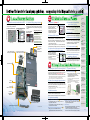
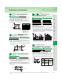
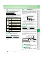
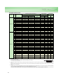
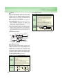
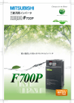
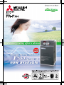
Evolution of the inverter for fan and pump applications, energy savings for buildings and factories as a whole
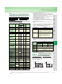
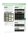
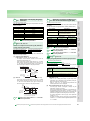
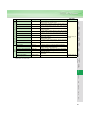
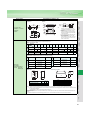
•Achieved a higher level of energy savings during acc./dec. to say
nothing of during constant speed.
•The effect of energy savings can be confirmed using the
operation panel, output terminal (FM, AM terminal) and
via networks with the newly developed energy saving
monitor.
Commercial
power
operation
100
80
60
V/F control
40
Optimum
excitation
control
20
0
10
20
30
40
50
60
[Ratio of Motor Power Consumption during Acc./Dec.]
Power Consumption Ratio (%)
Power Consumption (%)
[Ex. of Blower Operation Characteristics]
Driving of the Mitsubishi 400V 4 poles
45kW motors comparison
Conventional model(FR-F500)
Ex. of Power Savings
Monitor Display
100
6%
12%
90
FR-F700
0
Frequency (Hz)
10
20
30
40
50
Motor Lord Torque (%)
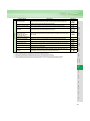
[Energy Saving Monitor List]
Power saving monitor (kW)
Power saving rate (%)
Power saving amount (kWh)
Power saving amount charge ($)
Power saving average value (kW)
Power saving rate average value (%)
Power saving charge average value ($)
Annual power saving amount (kWh)
Annual power saving amount charge ($)
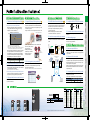
A
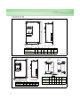
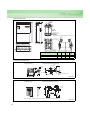
Easy replacement with
the cooling fan cassette!!
C
RS-485 communication is
possible with PU connector
H
A
Easy operation
with the setting
dial of the
operation panel
Connection with
Peripheral Devices
Why can the inverter
save energy?
5
Standard
Specifications
7
Outline Dimension
Drawings
9
Terminal Connection
Diagram
Terminal Specification
Explanation
16
Explanation of the
Operation Panel
(FR-DU07)
19
Parameter List
21
Explanations of
Parameters
28
Protective Functions
47
Option and
Peripheral Devices
49
Precautions for
Operation/Selection
Precautions for Peripheral
Device Selection
59
Application to Motor
63
Main differences and
compatibilities with
the FR-F500(L) series
64
Warranty
65
•Possible to copy parameters with operation panel A
•Parameter setting for multiple inverters is simple by
copy with the operation panel.
International FA center
66
•Alarm history
•Alarm history (alarm details and frequency, current, voltage
and cumulative energization time at time of alarm
occurrence) can be displayed on the operation panel and
the cause of a trouble can be checked.(up to 8 past alarms)
2
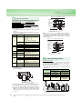
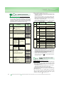
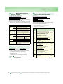
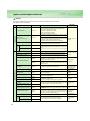
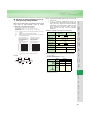
(1) Adjustable 5 points V/F
•Possible to set the torque
pattern that is optimum for the
machine's characteristic
•Possible to expect even more
energy savings with optimum
excitation control and optimum
V/F pattern working together
(4) Restart after instantaneous
power failure function
Voltage
V/F5
V/F
pattern V/F4
V/F3
Torque
characteristic
curves
V/F1
V/F2
0
Base
Frequency
V/F Characteristic
(2) Enhanced PID function
•Restart can be made without stopping the
motor when the motor is coasting due to an
instantaneous power failure.
(5) Flying start
•Smoothly restarts a motor that is rotating even in
the opposite direction due to the windmill effect.
•Energy savings in low speed region ... PID shutoff (sleep control) function
•Shorter PID startup time ... PID automatic switchover function
•Monitor of set point/measured value/deviation possible ... PID monitor
•Convenient for HVAC usage ... forward/reverse operation switchover
is simple with an external signal
•Corresponds to a wide range of detectors ... set point and measured value
for PID input can either be voltage (0 to 5V/0 to 10 V) or current (4 to 20mA)
(6) Regeneration avoidance function
(3) Adoption of the original operation continuation
•Protection of the motor can be certain since the
built-in PTC of the motor can be input directly in
addition to the electronic thermal relay function.
at instantaneous power failure function
•Operation continues without
the motor coasting when an
instantaneous power failure
occurred in fan and blower
applications.
When power is restored during deceleration
•Possible to avoid regeneration overvoltage alarm by
automatically increasing the frequency and continue
operation if the fan happens to rotate faster due to
the effect of another fan in the same duct.
(7) PTC thermistor input
I
PTC thermistor input…Positive Temperature Coefficient Thermistor
(8) Commercial power-supply
IPF
Input
Power Supply
switchover sequence
Output
Frequency
*The inverter may trip and the motor may
coast depending on the load condition.
RS-485 terminal
1
Frequency
(2) The effect of energy savings is obvious
Base
Frequency
Voltage
(1) Upgrade of the renown Optimum Excitation Control!!
Features
Deceleration
Reacceleration
•Switchover to commercial power-supply operation is
simple using R1 and S1 terminals of the control circuit
and commercial power-supply switchover sequence.
G
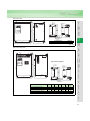
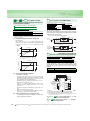
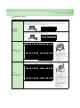
(1) Operating life of parts are further lengthened (4) Update is also easy
•Adoption of newly developed long life cooling fan (design life of 10 years*1)
Longer operating life is further enhanced with the use of ON/OFF control of cooling fan.
•Adoption of long life capacitor (design life of 10 years*1, 2)
A capacitor with specification of 5000 hours at 105˚C ambient temperature is adapted.
*1 Ambient temperature: yearly average 40˚C (free from corrosive gas, flammable gas, oil mist, dust and dirt)
Since the design life is a calculated value, it is not a guaranteed value.
*2 Output current: 80% of the rated current of Mitsubishi standard 4P motor
Built-in
EMC filter
AU/PTC
switchover switch
Connector
with/without
EMC filter
(2) State of the art longevity diagnostic method
E
•Degrees of deterioration of main circuit capacitor, control circuit
capacitor or inrush current limit circuit can be diagnosed by monitor.
•Trouble can be avoided with the self-diagnostic alarms* that is
output when the life span is near.
I
•Removable terminal block B
•When exchanging the inverter, the control
circuit terminals can be exchanged.
The removable terminal block of the FRF500 series can be used.
(The terminal block of the FR-F700 series is compatible with
that of the FR-F500 series.
Note that some functions of the FR-F700 series are restricted
when using the terminal block of the FR-F500 series.)
FR-F500 series
FR-F700 series
*Any of alarm for main circuit capacitor, control circuit capacitor, inrush current limit
circuit and cooling fan can be output.
(3) Maintenance timer
F
•Maintenance timer output function can also inform of
maintenance time for peripheral equipments.
•Average output current value and maintenance timer value are output as pulses.
(5) Improved workability
B
Combed shaped wiring cover
1
D
Removable terminal block
•Easy replacement of cooling fan C
•The installation position of the cooling fan is in the
upper portion of the inverter.
Fan replacement is easily done without having to
remove the main circuit wires.
Photo:FR-F740-5.5K
•Wiring is easy with the combed shaped wiring cover
•Wiring cover can be reinstalled after wiring.
(200V class 22K or less, 400V class 30K or less)
D
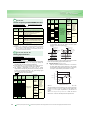
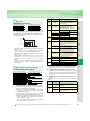
EN61800-3
second Environment QP level
(2) Possible to correspond with major networks
•Possible to connect with LONWORKS, CC-Link Ver.1.1 and Ver.2.0,
DeviceNetTM and Profibus-DP when used with communication
options
QP value
.3
.5
.7
1
2
3
5
7
10
20 30
Frequency [MHz]
*1: Refer to the EMC instruction manual for compliance conditions.
*2: Leakage current will increase when the EMC filter is selected.
*3: Since the leakage current when using the EMC filter for the 200V class 0.75K and
1.5K is small, the filter is always valid (a setting connector is not provided).
•Because of the built-in capacitive filter and zero-phase reactor (55K or less),
connecting the optional DC reactor to the inverter will comply with the
electric installation work common specification and machine installation
work common specification (2001) written under the general editorship of
the Japanese Ministry of land, infrastructure and transportation.
Capacitive filter Zero-phase reactor
55K or less
Standard (Built-in)
75K or more
Standard (Built-in)
Standard (Built-in)
•Operation panel is detachable and can be installed on the
front cover. (Cable connector
Power
supply
unit
Inverter
option is required.)
•Dial/key operation lock
FR-A7NC
function is available.
CC-Link
dedicated cable
Option (Sell separately)
(2) Countermeasures for harmonic current output
•Small AC reactor (FR-HAL) /DC reactor (FR-HEL)
•AC reactor and DC reactor options for the control of harmonics
current output has been miniaturized.
FR-A7NC
Terminating
resistor
CC-Link network
Inverter
(2) FR Configurator (setup software)
•12 contact inputs, 3 analog inputs, 5 open collector outputs, 2
relay outputs, analog output and pulse output are all standard.
•Possible to assign variety of functions to contact inputs, open
collector outputs and relay outputs
•Possible to switch between voltage and current for the analog input.
•Possible to display the ON/OFF status of the I/O terminals on
the operation panel
Inverter
Pump
Air-conditioner
•From start up to maintenance of the inverter is simple.
•Possible to save and print parameter setting file making
parameter management simple
FR-A7NL
FR-A7NL
LONWORKS
(Possible to use communications connecting to any of PU connector and RS-485 terminals)
Network
(DC reactor is supplied with the 75K or more as standard.)
•Connection with high power factor converter (FR-HC/MT-HC) is possible
•Connection is possible to high power-factor converter for effective
suppressions of power-supply harmonics (coefficient K5=0).
•You can utilize the on/off of the inverter's output signals
instead of the remote output function of the programmable
logic controller.
(2) Enhanced I/O is standard
Network management
computer
DC reactor
Option (Sell separately) Standard (supplied)
(1) Remote output function
when connections
Terminating
resistor
(3) Wide voltage range
•Accommodate both 240V power supply (55K or less) and
480V power supply as standard
Inverter
( are inverter only )
PU/EXT
Example of
operation mode
•Possible to switch the logic of I/O terminals. Possible to use in
all regions
Up to 42 units can
be connected
CPU Master
•PU/EXT (operation mode)
switchover key is available.
(2) Possible to switch sink/source with one-touch
Peripheral Devices
Why energy
savings?
Features
[dBuV]
Example of parameter change
Standard
Specifications
[FR-F740-37K Conducted noise data]
130
120
110
100
90
80
70
60
50
40
30
20
10
0
.15 .2
Outline
Dimension
Drawings
the dial is being turned.
•Settings are certain due to the "clicking" sensation and notch on dial.
Terminal Connection
Diagram
Terminal Specification
Explanation
•Settings can be made quickly or slowly depending on fast
•RS-485 terminals are available in addition to the PU.
connector. RS-485 communication can be performed using
the operation panel or parameter unit. Since terminals for
input and output are provided separately, multi-drop
connection is easily done.
•Modbus-RTU (Binary) protocol has been added for
communications in addition to computer link.
(1) Complies with UL, cUL, EN (LVD) standards
Operation
Panel
•Frequency and parameters can be set without frustrations.
H
Parameter
List
•Operation is easy with the popular setting dial.
(1) RS-485 terminal is standard equipped G
Explanations
of
Parameters
•Newly developed noise filter (EMC filter)
•Because of the built-in EMC filter, the inverter itself can
comply with the EMC Directive (2nd environment *1 ) by
setting the connector to "with filter"(*2,*3).
A
Protective
Functions
•Inverter noises have been reduced with the adoption of new technologies.
(1) Equipped with operation panel with the popular setting dial
(3) Simple magnetic flux vector control is possible
Free
Topology
Node
Options
E F
•High torque in low speed region is possible with simple
magnetic flux vector control
(120% torque is possible at 3Hz with slip compensation)
Node
(3) Equipped with inrush current limit circuit
Instructions
(1) Reduction of electromagnetic noises
V/F + Optimum Excitation Simple Magnetic Flux Vector
•Because of the built-in inrush current limit circuit, the current
at power on is restricted.
Security system
Motor
Lighting
For torque
For energy savings
Voltage
2
4
200V class
400V class
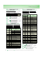
Symbol
Inverter Capacity
0.75K to 560K Indicate capacity (kW)
:Available models
3
LONWORKS® is a registered trademark of Echelon Corporation and DeviceNet is of ODVA.
Compatibility
Warranty
Symbol
Applied Motor Three-phase 200V class Three-phase 400V class
(kW)
FR-F720FR-F74075
90
110
132
160
185
220
250
280
315
355
400
450
500
560
Inquiry
FR-F720-0.75K
Applied Motor Three-phase 200V class Three-phase 400V class
(kW)
FR-F720FR-F7400.75
1.5
2.2
3.7
5.5
7.5
11
15
18.5
22
30
37
45
55
:Not available
4
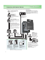
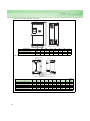
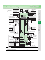
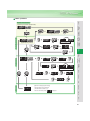
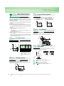
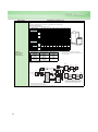
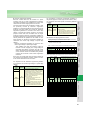
Connection with Peripheral Devices
Peripheral devices necessary for driving the FR-F700 series inverter are indicated below.
Inverter (FR-F700)
Three-phase AC power supply
Use within the permissible power supply
specifications of the inverter.
(Refer to page 7.)
The life of the inverter is influenced by ambient temperature.
The ambient temperature should be as low as possible within
the permissible range. (Refer to page 8.) This must be noted
especially when the inverter is installed in an enclosure.
Wrong wiring might lead to damage of the inverter. The control
signal lines must be kept fully away from the main circuit to
protect them from noise.
PLC
Moulded case circuit
breaker (MCCB)
or earth leakage circuit
breaker (ELB), fuse
RS-485 terminal block
The inverter can be
connected with computers
such as PLC.
It supports Mitsubishi inverter
protocol and Modbus-RTU
(binary) protocol.
The breaker must be selected carefully since
an in-rush current flows in the inverter at
power on.
(Refer to page 57.)
Magnetic contactor(MC)
Install the magnetic contactor to ensure safety.
Do not use this magnetic contactor to start and
stop the inverter.
Doing so will cause the inverter life to be shorten.
(Refer to page 57.).
Reactor (FR-HAL, FR-HEL)
Reactors (option) should be used when power
harmonics measures are taken, the power factor
is to be improved or the inverter is installed near a
large power supply system (1000kVA or more).
The inverter may be damaged if you do not use
reactors.
Select the reactor according to the model.
For the 55K or less, remove the jumpers across
terminals P/+-P1 to connect to the DC reactor.
(Refer to page 51.).
AC reactor
(FR-HAL)
Noise filter
(FR-BSF01, FR-BLF)
DC reactor
(FR-HEL)
(Refer to page 51.)
Noise filter
(FR-BLF)
For the 75K or more, a DC
reactor is supplied.
Always install the reactor.
P/+ P1 R/L1 S/L2 T/L3 P/+ N/-
Earth
(Ground)
U V W
(Refer to page 51.)
It is not necessary
for the 55K or less.
Install a noise filter to reduce
the electromagnetic noise
generated from the inverter.
Effective in the range from
about 1MHz to 10MHz.
When more wires are passed
through, a more effective result
can be obtained.
Motor
Brake unit
(FR-BU*1, MT-BU5*2)
Earth
(Ground)
P/+ PR
P/+
High power factor
converter
(FR-HC*1, MT-HC*2)
Power regeneration
common converter
(FR-CV*1)
Power regeneration
converter (MT-RC*2)
Power supply harmonics
can be greatly suppressed.
Install this as required.
Greater braking capability
is obtained.
Install this as required.
PR
Resistor unit
(FR-BR*1, MT-BR5*2)
The regenerative braking
capability of the inverter can be
exhibited fully.
Install this as required.
*1 Compatible with the 55K or less.
*2 Compatible with the 75K or more.
Refer to page 49 for the option list and details.
5
Devices connected to the output
Do not install a power factor correction capacitor,
surge suppressor or radio noise filter on the output
side of the inverter.
When installing a moulded case circuit breaker on the
output side of the inverter, contact each manufacturer
for selection of the moulded case circuit breaker.
Earth (Ground)
To prevent an electric shock, always earth
(ground) the motor and inverter.
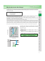
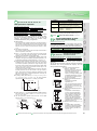
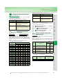
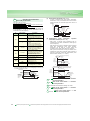
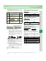
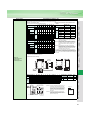
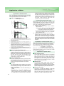
The load torque of a motor-driven machine generally changes depending on speed. On the other hand, motor output is
proportional to the product of load torque and speed as indicated in the following formula, and therefore, necessary motor
output varies with speed.
(1)Damper control
15kW×0.9×17 yen×24h×365days
(2)Inverter control
15kW×0.3×17 yen×24h×365days
60
Amount of
energy saved
2.01 million yen
0.67 million yen
40
Inverter control
20
0
40
60
80
(1) - (2) = energy-saving effect
Approx. 1.34 million yen
Outline
Dimension
Drawings
Terminal Connection
Diagram
Terminal Specification
Explanation
Operation
Panel
100
Instructions
Power Consumption (%)
80
Parameter
List
100
For example, when a 15kW motor is operated at 60% air volume and
the power charge is 17 yen/kW·h, the power charge as much as below
can be saved in a year.
Explanations
of
Parameters
Damper control (discharge side)
Protective
Functions
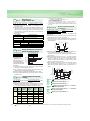
Motor speed control enables substantial energy-saving operation as compared to commercial power supply operation.
Options
When this motor is operated by the inverter, the inverter output provides the frequency f appropriate to the motor speed,
and the then output voltage V is determined by a "V/f = constant" pattern in the case of a constant-torque load.
For example, when the motor is operated at middle speed, f, i.e. output voltage V, decreases, and therefore, the inverter
output power V × I reduces if the output current I is constant.
Proportionately, the inverter input current decreases and the power consumption reduces. Namely, when the motor output
reduces, the input power of the inverter also decreases as a matter of course.
The fundamental principle of energy saving by the inverter is to eliminate wasted power consumption by minimizing loss
caused by the other devices and minimizing the motor output as compared to the other system (for example, commercial
power supply operation or secondary resistance control of wound-rotor motor). A maximum energy saving effect is
produced on a fan, pump or like by the variable-torque load characteristic that reduces load torque as speed decreases.
Standard
Specifications
Peripheral Devices
Why energy
savings?
Motor output P = T × N/(9550 × η) [kW]
T : Motor shaft-equivalent load torque [N·m]
N : Motor speed [r/min]
η : Machine efficiency
Features
Why Can the Inverter Save Energy?
Air volume (%)
Damper control
Inverter
energy-saving
control
15kW
15kW
Save
1,340,000
a year
Compatibility
2,010,000
Motor
15kW
Inquiry
Warranty
670,000
6
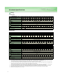
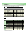
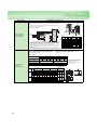
Standard Specifications
Rating
z200V class
Type FR-F720-K
Applied motor capacity (kW)*1
Output
Rated capacity (kVA)*2
Rated current (A)*3
0.75
1.5
2.2
3.7
5.5
7.5
11
15
18.5
22
30
37
45
55
75
90
0.75
1.5
2.2
3.7
5.5
7.5
11
15
18.5
22
30
37
45
55
75
90
110
1.6
2.7
3.7
5.8
8.8
11.8
17.1 22.1
27
32
43
53
65
81
110
132
165
4.2
7.0
9.6 15.2
(3.6) (6.0) (8.2) (13)
23
(20)
31
(26)
45
(38)
70
(60)
85
(72)
Overload current rating*4
114 140 170 212 288 346 432
(97) (119) (145) (180) (244) (294) (367)
120% 60s, 150% 3s (inverse time characteristics)
Voltage*5
Power supply
58
(49)
Three-phase 200 to 240V
Rated input AC voltage/frequency
Three-phase 200 to 220V 50Hz, 200 to 240V 60Hz
Permissible AC voltage fluctuation
170 to 242V 50Hz, 170 to 264V 60Hz
Permissible frequency fluctuation
±5%
Power supply system capacity (kVA)*6
2.5
4.5
5.5
9
Protective structure (JEM 1030)*8
Cooling system
Approx. mass (kg)
110
12
17
20
28
34
41
52
65
Enclosed type (IP20)*7
Self-cooling
1.8
2.2
79
99
110
132
165
70
70
Open type (IP00)
Forced air cooling
3.5
3.5
3.5
6.5
6.5
7.5
13
13
14
23
35
35
67
z400V class
Type FR-F740-K
Applied motor capacity (kW)*1
Output
Rated capacity (kVA)*2
Rated current (A)*3
0.75
1.5
2.2
3.7
5.5
7.5
11
15
18.5
22
30
37
45
0.75
1.5
2.2
3.7
5.5
7.5
11
15
18.5
22
30
37
45
55
1.6
2.7
3.7
5.8
8.8
12.2
17.5
22.1
26.7
32.8
43.4
53.3
64.8
80.8
2.1
(1.8)
3.5
(3.0)
4.8
(4.1)
7.6
(6.4)
11.5
(9.8)
16
(13)
23
(19)
29
(24)
35
(30)
43
(36)
57
(48)
70
(60)
85
(72)
106
(90)
52
66
80
100
Overload current rating*4
120% 60s, 150% 3s (inverse time characteristics)
Power supply
Voltage*5
Three-phase 380 to 480V
Rated input AC voltage/frequency
Three-phase 380 to 480V 50Hz/60Hz
Permissible AC voltage fluctuation
323 to 528V 50Hz/60Hz
Permissible frequency fluctuation
±5%
Power supply system capacity (kVA)*6
2.5
4.5
5.5
9
Protective structure (JEM 1030)*8
Type FR-F740-K
Applied motor capacity (kW)*1
Output
Rated capacity (kVA)*2
Rated current (A)*3
12
17
28
34
41
Self-cooling
Open type (IP00)
Forced air cooling
3.5
3.5
3.5
3.5
3.5
6.5
75
90
110
132
160
185
220
250
280
315
355
75
90
110
132
160
185
220
250
280
315
355
110
137
165
198
247
275
329
366
416
464
520
6.5
7.5
7.5
13
Overload current rating*4
35
35
400
450
500
560
400
450
500
560
586
659
733
833
Three-phase 380 to 480V
Three-phase 380 to 480V 50Hz/60Hz
Permissible AC voltage fluctuation
323 to 528V 50Hz/60Hz
Permissible frequency fluctuation
±5%
110
137
165
198
247
275
329
366
416
Protective structure (JEM 1030)*8
Open type (IP00)
Cooling system
Forced air cooling
Approx. mass (kg)
23
120% 60s, 150% 3s (inverse time characteristics)
Rated input AC voltage/frequency
Power supply system capacity (kVA)*6
13
144
180
216
260
325
361
432
481
547
610
683
770
866
962 1094
(122) (153) (183) (221) (276) (306) (367) (408) (464) (518) (580) (654) (736) (817) (929)
Voltage*5
Power supply
20
Enclosed type (IP20)*7
Cooling system
Approx. mass (kg)
55
37
50
57
72
72
110
110
175
175
464
520
586
659
733
833
175
260
260
370
370
370
*1. The applied motor capacity indicated is the maximum capacity applicable for use of the Mitsubishi 4-pole standard motor.
*2. The rated output capacity indicated assumes that the output voltage is 220V for 200V class and 440V for 400V class.
*3. When operating the inverter with the carrier frequency set to 3kHz or more, the carrier frequency automatically decreases if the inverter output
current exceeds the value in parenthesis of the rated current. This may cause the motor noise to increase.
*4. The % value of the overload current rating indicated is the ratio of the overload current to the inverter's rated output current. For repeated duty,
allow time for the inverter and motor to return to or below the temperatures under 100% load.
*5. The maximum output voltage does not exceed the power supply voltage. The maximum output voltage can be changed within the setting range.
However, the pulse voltage value of the inverter output side voltage remains unchanged at about 2 that of the power supply.
*6. The power supply capacity varies with the value of the power supply side inverter impedance (including those of the input reactor and cables).
*7. When the hook of the inverter front cover is cut off for installation of the plug-in option, the inverter changes to an open type (IP00).
*8. FR-DU07 : IP40 (Except for the PU connector).
7
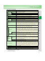
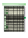
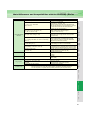
Operational functions
Operating status
Output signals
Operation specifications
When used with the
FR-A7AY, FR-A7AR
(option)
Display
Pulse/analog output
PU
(FR-DU07/
FR-PU04)
Operating status
Alarm definition
Interactive guidance
Environment
Protective/warning function
*1.
*2.
*3.
*4.
Selection can be made from output frequency, motor current (steady or peak value), output voltage, frequency setting
value, running speed, converter output voltage (steady or peak value), electronic thermal relay function load factor,
input power, output power, load meter, reference voltage output, motor load factor, power saving effect, regenerative
brake duty*4, PID set value, PID measured value using Pr.54 "FM terminal function selection (pulse train output)" and
Pr.158 "AM terminal function selection (analog output)".
Output frequency, motor current (steady or peak value), output voltage, frequency setting, running speed, converter
output voltage (steady or peak value), electronic thermal relay function load factor, input power, output power, load
meter, cumulative energization time, actual operation time, motor load factor, cumulative energization power, power
saving effect, cumulative saving power, regenerative brake duty*4, PID set point, PID measured value, PID deviation
value, inverter I/O terminal monitor, input terminal option monitor*1, output terminal option monitor*1, option fitting
status monitor*2, terminal assignment status*2
Alarm definition is displayed when the protective function is activated, the output voltage/current/frequency/cumulative
energization time right before the protection function was activated and the past 8 alarm definitions are stored
Operation guide/trouble shooting with a help function*2
Overcurrent during acceleration, overcurrent during constant speed, overcurrent during deceleration, overvoltage
during acceleration, overvoltage during constant speed, overvoltage during deceleration, inverter protection thermal
operation, motor protection thermal operation, heatsink overheat, instantaneous power failure occurrence,
undervoltage, input phase failure, motor overload, output side earth (ground) fault overcurrent, output phase failure,
external thermal relay operation, PTC thermistor operation, option alarm, parameter error, PU disconnection, retry
count excess, CPU alarm, operation panel power supply short circuit, 24VDC power output short circuit, output
current detection value excess, inrush resistance overheat, communication alarm (inverter), analog input alarm,
internal circuit alarm (15V power supply), fan fault, overcurrent stall prevention, overvoltage stall prevention,
electronic thermal relay function prealarm, PU stop, maintenance timer alarm*1, brake transistor alarm*4, parameter
write error, copy operation error, operation panel lock, parameter copy alarm
Ambient temperature
Ambient humidity
Storage temperature*3
Atmosphere
-10°C to +50°C (non-freezing)
90%RH or less (non-condensing)
-20°C to +65°C
Indoors (without corrosive gas, flammable gas, oil mist, dust and dirt etc.)
Altitude, vibration
Maximum 1000m above seal level, 5.9m/s2 or less at 10 to 55Hz (directions of X, Y, Z axes) *5
Can be displayed only on the operation panel (FR-DU07).
Can be displayed only on the parameter unit (FR-PU04).
Temperature applicable for a short period in transit, etc.
Only the 75K or more functions.
Peripheral Devices
Why energy
savings?
Standard
Specifications
Outline
Dimension
Drawings
Terminal Connection
Diagram
Terminal Specification
Explanation
Input signals
Available individually for forward rotation and reverse rotation. Start signal automatic self-holding input (3-wire input)
can be selected.
You can select any twelve signals using Pr.178 to Pr.189 (input terminal function selection) from among multi speed
selection, second function selection, terminal 4 input selection, JOG operation selection, selection of automatic
restart after instantaneous power failure, external thermal relay input, HC connection (inverter operation enable
signal), HC connection (instantaneous power failure detection), PU operation/external inter lock signal , PID control
enable terminal, PU operation, external operation switchover, output stop, start self-holding selection, forward
rotation command, reverse rotation command, inverter reset, PTC thermistor input, PID forward reverse operation
switchover, PU-NET operation switchover, NET-external operation switchover, command source switchover.
Maximum and minimum frequency settings, frequency jump operation, external thermal relay input selection, polarity
reversible operation, automatic restart after instantaneous power failure operation, original operation continuation at
instantaneous power failure, commercial power supply-inverter switchover operation, forward/reverse rotation
prevention, operation mode selection, PID control, computer link operation (RS-485).
You can select any seven signals using Pr.190 to Pr.196 (output terminal function selection) from among inverter
running, up-to-speed, instantaneous power failure /undervoltage, overload warning, output frequency detection, second
output frequency detection, regenerative brake prealarm*4, electronic thermal relay function pre-alarm, PU operation
mode, inverter operation ready, output current detection, zero current detection, PID lower limit, PID upper limit, PID
forward rotation reverse rotation output, commercial power supply-inverter switchover MC1, commercial power supplyinverter switchover MC2, commercial power supply-inverter switchover MC3, fan fault output, heatsink overheat prealarm, inverter running start command on, deceleration at an instantaneous power failure, PID control activated, during
retry, during PID output suspension, life alarm, alarm output 3 (power-off signal), power savings average value update
timing, current average monitor, alarm output 2, maintenance timer alarm, remote output, minor failure output, alarm
output. Open collector output (5 points), relay output (2 points) and alarm code of the inverter can be output (4 bit) from
the open collector.
You can select any seven signals using Pr.313 to Pr. 319 (extension output terminal function selection) from among
control circuit capacitor life, main circuit capacitor life, cooling fan life, inrush current limit circuit life and the above
stated signals. (Only positive logic can be set for terminals of the FR-A7AR.)
Operation
Panel
Start signal
Parameter
List
Digital input
Terminal 2, 4: 0 to 10V, 0 to 5V, 4 to 20mA can be selected
Terminal 1: -10 to +10V, -5 to 5V can be selected
Four-digit BCD or16-bit binary using the setting dial of the operation panel (when used with the option FR-A7AX)
Explanations
of
Parameters
Analog input
Protective
Functions
Frequency
setting signal
Options
DC injection brake
Stall prevention operation level
Instructions
Acceleration/deceleration time setting
Motor
Starting torque
Within 0.01% of the set output frequency
Base frequency can be set from 0 to 400Hz Constant torque/variable torque pattern or adjustable 5 points V/F can
be selected
120% (3Hz) when set to simple magnetic flux vector control and slip compensation
0 to 3600s (acceleration and deceleration can be set individually), linear or S-pattern acceleration/deceleration mode
can be selected.
Operation frequency (0 to 120Hz), operation time (0 to 10s), operation voltage (0 to 30%) variable
Operation current level can be set (0 to 150% adjustable), whether to use the function or not can be selected
Compatibility
Voltage/frequency characteristics
Warranty
Analog input
Frequency
setting resolution
Digital input
Analog input
Frequency
accuracy
Digital input
High carrier frequency PWM control (V/F control)/optimum excitation control/simple magnetic flux vector control
0.5 to 400Hz
0.015Hz/0 to 60Hz (terminal 2, 4: 0 to 10V/12bit)
0.03Hz/0 to 60Hz (terminal 2, 4: 0 to 5V/11bit, 0 to 20mA/11bit, terminal 1: 0 to ±10V/12bit)
0.06Hz/0 to 60Hz (terminal 1: 0 to ±5V/11bit)
0.01Hz
Within ±0.2% of the max. output frequency (25°C ± 10°C)
Inquiry
Control specifications
Control system
Output frequency range
Features
Common specifications
*5. 2.9m/s2 or less for the 185K or more.
8
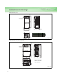
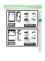
Outline Dimension Drawings
7.5
z FR-F720-0.75K, 1.5K
245
260
2-φ6 hole
6
5
7.5
95
110
D
Inverter Type
D
D1
110
125
21
36
D1
FR-F720-0.75K
FR-F720-1.5K
(Unit: mm)
z FR-F720-2.2K, 3.7K, 5.5K
7.5
z FR-F740-0.75K, 1.5K, 2.2K, 3.7K, 5.5K
6
125
150
7.5
245
260
2-φ6 hole
140
5
45.5
* The FR-F740-0.75K to
2.2K are not provided
with a cooling fan.
144
(Unit: mm)
9
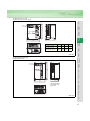
z FR-F720-7.5K, 11K, 15K
7.5
Features
z FR-F740-7.5K, 11K, 15K, 18.5K
Peripheral Devices
Why energy
savings?
Outline
Dimension
Drawings
D
10
220
D1
Inverter Type
FR-F720-7.5K, 11K
FR-F740-7.5K, 11K
FR-F720-15K
FR-F740-15K, 18.5K
H
H1
D
D1
260
245
170
84
300
285
190
101.5
Terminal Connection
Diagram
Terminal Specification
Explanation
195
Operation
Panel
6
7.5
Standard
Specifications
H
H1
2-φ6 hole
(Unit: mm)
z FR-F720-18.5K, 22K, 30K
10
Explanations
of
Parameters
z FR-F740-22K, 30K
Parameter
List
211
10
Instructions
Options
380
400
Protective
Functions
2-φ10 hole
230
250
10.5
Motor
190
Warranty
101.5
Compatibility
* The FR-F720-30K is
not provided with a
wiring cover.
250
(Unit: mm)
Inquiry
10
10
z FR-F720-37K, 45K, 55K
z FR-F740-37K, 45K, 55K
10
H
550
H1
2-φd hole
W2
3.2
W1
W
D
Inverter Type
FR-F720-37K
FR-F740-37K
FR-F720-45K, 55K
FR-F740-45K, 55K
W
W1
W2
H
H1
d
D
325
270
10
530
10
10
195
435
380
12
525
15
12
250
(Unit: mm)
z FR-F740-75K, 90K
• DC reactor supplied
15
2-φ12 hole
Rating plate
2-terminal
(for M12 bolt)
P1
P
H
H1
H 10
H1 10
P1, P
E
4-installation hole
(for M6 screw)
W1
W
Within D
10
Earth (ground) terminal
(for M6 screw)
12
3.2
W1
W
Inverter Type
FR-F740-75K
FR-F740-90K
D
W
W1
H
H1
D
435
465
380
400
525
595
550
620
250
300
Inverter Type
W
W1
H
H1
D
Mass
(kg)
FR-F740-75K
(FR-HEL-H75K)
140
120
320
295
185
16
FR-F740-90K
(FR-HEL-H90K)
150
130
340
310
190
20
(Unit: mm)
11
15
zFR-F740-110K
Features
z DC reactor supplied
Rating plate
Standard
Specifications
340 10
P
P
E
4-installation hole
(for M6 screw)
130
150
Within 195
Earth (ground) terminal
(for M6 screw)
Mass (kg)
Inverter Type
FR-F740-110K(FR-HEL-H110K)
3.2
10
400
300
465
22
(Unit: mm)
zFR-F720-75K, 90K, 110K
15
Operation
Panel
zFR-F740-132K, 160K
Outline
Dimension
Drawings
310 10
P1
620
595
P1
Peripheral Devices
Why energy
savings?
2-terminal
(for M12 bolt)
Terminal Connection
Diagram
Terminal Specification
Explanation
2-φ12hole
Explanations
of
Parameters
Parameter
List
2-φ12 hole
Protective
Functions
715
740
z DC reactor supplied
Rating plate
P1
H 10
H1 10
P1
10
360
3.2
Instructions
P
P
E
4-installation hole
(for S screw)
W1
W
Within D
FR-F720-75K(FR-HEL-75K)
FR-F720-90K(FR-HEL-90K)
FR-F720-110K(FR-HEL-110K)
FR-F740-132K(FR-HEL-H132K)
FR-F740-160K(FR-HEL-H160K)
W
W1
H
H1
D
S
Mass
(kg)
150
150
175
175
175
130
130
150
150
150
340
340
400
405
405
310
310
365
370
370
190
200
200
200
205
M6
M6
M8
M8
M8
17
19
20
26
28
(Unit: mm)
Warranty
Inverter Type
Compatibility
Motor
Earth (ground) terminal
(for M6 screw)
Inquiry
400
465
Options
2-terminal
(for M12 bolt)
12
H2
z FR-F740-185K, 220K, 250K, 280K, 315K, 355K
W1
W1
3.2
H3
W2
H
H1
3-φ12 hole
12
D
W
Inverter Type
FR-F740-185K, 220K
FR-F740-250K, 280K, 315K
FR-F740-355K
W
W1
W2
H
H1
H2
H3
D
498
680
790
200
300
315
49
40
80
1010
1010
1330
985
985
1300
15
15
15
10
10
15
380
380
440
z DC reactor supplied
Rating plate
2-S2 eye nut
2-terminal (for
P1
bolt)
H 10
H1 10
P1
P
P
E
W1
4-installation hole
(for S screw)
W
Within D
Earth (ground) terminal
(for S1 screw)
* Remove the eye nut after installation of the product.
Inverter Type
FR-F740-185K(FR-HEL-H185K)
FR-F740-220K(FR-HEL-H220K)
FR-F740-250K(FR-HEL-H250K)
FR-F740-280K(FR-HEL-H280K)
FR-F740-315K(FR-HEL-H315K)
FR-F740-355K(FR-HEL-H355K)
W
W1
H
H1
D
S
S1
S2
φ
Mass
(kg)
175
175
190
190
210
210
150
150
165
165
185
185
405
405
440
440
495
495
370
370
400
400
450
450
240
240
250
255
250
250
M8
M8
M8
M8
M10
M10
M6
M6
M8
M8
M8
M8
M6
M8
M8
M8
M8
M12
M12
M12
M16
M16
M16
29
30
35
38
42
46
(Unit: mm)
13
• DC reactor supplied
Rating plate
Peripheral Devices
Why energy
savings?
2-M8 eye nut
P1
40
Outline
Dimension
Drawings
75
P
40
P
Standard
Specifications
10
10
455
500
1330
1300
P1
E
195
4-installation hole
(for M10 screw)
220
12
315
315
4.5
790
T/L3
S/L2
440
P1
U
P/+
N/-
Earth (ground) terminal
(for M8 screw)
W
V
Within 250
Within 235
* Remove the eye nut after installation of the product.
194
R/L1
4.5
Mass
(kg)
185
222
Inverter Type
FR-F740-400K(FR-HEL-H400K)
50
Terminal Connection
Diagram
Terminal Specification
Explanation
2-terminal
4- 15 hole
Operation
Panel
3-φ12 hole
Features
z FR-F740-400K
z FR-F740-450K
• DC reactor supplied
4-φ12 hole
Rating plate
2-M8 eye nut
2-terminal
4- 15 hole
Protective
Functions
P1
Instructions
75
P
40
P
Options
10
10
455
500
1580
E
195
220
300
440
995
950
P/+
V
189
P1
Within 240
Earth (ground) terminal
(for M8 screw)
227
185
R/L1 S/L2 T/L3 N/-
Within 270
4.5
* Remove the eye nut after installation of the product.
Inverter Type
FR-F740-450K(FR-HEL-H450K)
Mass
(kg)
57
(Unit: mm)
Motor
300
Compatibility
4.5
300
Warranty
12
4-installation hole
(for M10 screw)
Inquiry
1550
P1
40
Explanations
of
Parameters
Parameter
List
(Unit: mm)
14
z FR-F740-500K, 560K
• DC reactor supplied
4-φ12 hole
40
Rating plate
P1
1580
1550
2-terminal
4- 15 hole
Earth (ground) terminal
(for M12 screw)
P
E
* Remove the eye nut after installation of the product.
75
Within 245
2-M12 eye nut
40
4.5
300
300
300
4.5
Within H
12
440
995
950
P/+
189
V
227
P1
185
R/L1 S/L2 T/L3 N/-
P1
P
150
4-installation hole
(for M10 screw)
215
10
D
10
H
D
D1
Mass
(kg)
345
360
455
460
405
410
67
85
Inverter Type
FR-F740-500K(FR-HEL-H500K)
FR-F740-560K(FR-HEL-H560K)
D1
(Unit: mm)
z Operation panel (FR-DU07)
<Outline drawing>
<Panel cutting dimension drawing>
Panel
FR-DU07
27.8
21
Airbleeding
hole
22
44
50
44
6
3
3.2max
20
3
3
72
78
81
16
3
2-M3 screw
Cable
72
Operation panel connection connector
(FR-ADP)
25
(Unit: mm)
z Parameter unit (option) (FR-PU04)
<Outline drawing>
<Panel cutting dimension drawing>
16.5
24
1.25
1.5
5-φ4 hole
13 1.5
17
20
14.5
80
125
23.75
11.75
81.5
10.5
18.5
15
13
21.5
72
48
5-M3 screw
Effective
depth 4.5
40
40
Select the installation screws whose length will not exceed the effective depth of the installation screws threads.
(Unit: mm)
15
R1/L11
S1/L21
Main circuit
B1
STR
A1
STOP
RL
RT
SU
*3. AU terminal
can be used Output stop
as PTC input
Reset
terminal.
MRS
IPF
Terminal 4 input selection
(Current input selection)
Selection of automatic restart
after instantaneous
power failure
Contact input common
AU
24VDC power supply
(Common for external power supply transistor)
PC
Second function selection
RES *3
0 to 5VDC
2 0 to 10VDC
selected *4
4 to 20mADC
5
(Analog common)
2
1
Auxiliary input (+)
(-)
Terminal 4 input (+)
(Current input) (-)
1
0 to ±10VDC
0 to ±5VDC selected *4
4
4 to 20mADC
0 to 5VDC selected *4
0 to 10VDC
Connector
for plug-in option
connection
*5. It is recommended to use
2W1kΩ when the
frequency setting signal is
changed frequently.
SE
+
Indicator
- (Frequency meter, etc.)
Calibration
resistor *9
Moving-coil type
1mA full-scale
FM
SD
AM
5
(+)
(-)
Analog signal output
(0 to 10VDC)
RS-485 terminals
TXD+
TXD-
Data transmission
RXD+
RXDSG
Option connector 1
Open collector output common
Sink/source common
*9. It is not necessary
when calibrating the
indicator from the
operation panel.
PU
connector
10E(+10V)
10(+5V)
3
Overload
Frequency detection
SINK
SD
Terminal functions
Up to frequency vary with the output
terminal assignment
Instantaneous (Pr. 190 to Pr. 194)
power failure
FU
SOURCE
CS PTC
Frequency setting signal (Analog)
*4. Terminal input
specifications can be
changed by analog input
specifications switchover
(Pr. 73, Pr. 267).
OL
AU
Open collector output
Running
Terminating
resistor VCC
Data reception
GND
5V (Permissible load
current 100mA)
CAUTION
⋅ To prevent a malfunction due to noise, keep the signal cables more than 10cm away from the power cables.
⋅ Be sure to use the inverter and motor after grounding (earthing) them.
⋅ This connection diagram assumes that the control circuit is sink logic (initial setting). Refer to the instruction manual for the
connection in the case of source logic.
Parameter
List
RUN
Explanations
of
Parameters
JOG
Jog mode
Frequency setting
potentiometer
1/2W1kΩ
*5
Operation
Panel
Relay output 2
A2
Low speed
Peripheral Devices
Why energy
savings?
B2
RM
Middle speed
Terminal functions
Relay output 1 vary with the output
(Alarm output) terminal assignment
(Pr. 195, Pr. 196)
C2
RH
High speed
Relay output
Protective
Functions
Start self-holding selection
C1
STF
Options
Control input signals (No voltage input allowed)
Forward
Terminal functions
rotation
start
vary with the input
Reverse
terminal assignment
rotation
(Pr. 178 to Pr. 189)
start
Control circuit
Instructions
Earth
(Ground)
Earth
(ground)
cable
*8. The 200V class 0.75K and 1.5K
are not provided with the ON/OFF
connector of the EMC filter.
Motor
*2. To supply power to the
control circuit separately,
remove the jumper across
R1/L11 and S1/L21.
*2
IM
Compatibility
Jumper
Motor
Standard
Specifications
PX*7 N/- CN8*6
U
V
W
ON Connector for
with/without
OFF EMC filter *8
PR*7
*7. Do not use PR and PX terminals.
Please do not remove the jumper
connected to terminal PR and PX.
Outline
Dimension
Drawings
P/+
R/L1
S/L2
T/L3
Three-phase AC
power supply
Jumper
Terminal Connection
Diagram
Terminal Specification
Explanation
Jumper
P1
MC
MCCB
Multi-speed
selection
Earth
(ground)
*6. A CN8 connector is
provided with the
75K or more.
Warranty
Control circuit terminal
Resistor unit
(Option)
Brake unit
(Option)
*1
Inquiry
*1. DC reactor (FR-HEL)
Be sure to connect the DC reactor
supplied with the 75K or more.
When a DC reactor is connected
to the 55K or less, remove the
jumper across P1-P/+.
Sink logic
Main circuit terminal
Features
Terminal Connection Diagram
16
Terminal Specification Explanation
Type
Terminal Symbol
R/L1, S/L2, T/L3
U, V, W
Main circuit
R1/L11, S1/L21
P/+, N/P/+, P1
PR, PX
Terminal Name
AC power input
Inverter output
Power supply for control
circuit
Description
Connect to the commercial power supply.
Connect a three-phase squirrel-cage motor.
Connected to the AC power supply terminals R/L1 and S/L2. To retain the alarm display and
alarm output, apply external power to this terminal.
Connect the brake unit (FR-BU, BU, MT-BU5), power regeneration common converter (FRBrake unit connection
CV), power regeneration converter (MT-RC) or high power factor converter (FR-HC, MT-HC).
For the 55K or less, remove the jumper across terminals P/+ - P1 and connect the DC reactor.
DC reactor connection
(For the 75K or more, a DC reactor is supplied as standard.)
Please do not remove or use terminals PR and PX or the jumper connected.
Earth (Ground)
STF
Forward rotation start
STR
Reverse rotation start
STOP
RH, RM, RL
JOG
RT
Contact input
MRS
RES
Control circuit input signal
AU
CS
SD
PC
10E
10
Frequency setting
2
4
1
5
17
Start self-holding
selection
Multi-speed selection
For earthing (grounding) the inverter chassis. Must be earthed (grounded).
Turn on the STF signal to start forward rotation and turn it off to
stop.
Turn on the STR signal to start reverse rotation and turn it off to
stop.
When the STF and STR
signals are turned on
simultaneously, the stop
command is given.
Turn on the STOP signal to self-hold the start signal.
Multi-speed can be selected according to the combination of RH, RM and RL signals.
Turn on the JOG signal to select Jog operation (initial setting) and turn on the start signal (STF
Jog mode selection
or STR) to start Jog operation.
Second acceleration/
Turn on the RT signal to select second acceleration/deceleration time.
deceleration time
When the second function such as "second torque boost" and "second V/F (base frequency)"
selection
are set, turning on the RT signal selects these functions.
Turn on the MRS signal (20ms or more) to stop the inverter output.
Output stop
Use to shut off the inverter output when stopping the motor by electromagnetic brake.
Used to reset alarm output provided when protective function is activated. Turn on the RES
Reset
signal for more than 0.1s, then turn it off.
Recover about 1s after reset is cancelled.
Terminal 4 is made valid only when the AU signal is turned on. (The frequency setting signal
Terminal 4 input selection can be set between 4 and 20mADC.)
Turning the AU signal on makes terminal 2 (voltage input) invalid.
AU terminal is used as PTC input terminal (thermal protection of the motor). When using it as
PTC input
PTC input terminal, set the AU/PTC switch to PTC.
Selection of automatic
When the CS signal is left on, the inverter restarts automatically at power restoration. Note that
restart after
restart setting is necessary for this operation. In the initial setting, a restart is disabled.
instantaneous power
failure
Contact input common
Common terminal for contact input terminal (sink logic) and terminal FM. Common output
(sink)
terminal for 24VDC 0.1A power supply (PC terminal). Isolated from terminals 5 and SE.
External transistor
When connecting the transistor output (open collector output), such as a programmable
common,
controller (PLC), when sink logic is selected, connect the external power supply common for
24VDC power supply,
transistor output to this terminal to prevent a malfunction caused by undesirable currents. Can
contact input common
be used as 24VDC 0.1A power supply. When source logic has been selected, this terminal
(source)
serves as a contact input common.
10VDC, permissible load
When connecting the frequency setting potentiometer at an initial
current 10mA.
Frequency setting power
status, connect it to terminal 10.
supply
5VDC, Permissible load
Change the input specifications when connecting it to terminal 10E.
current 10mA.
Inputting 0 to 5VDC (or 0 to 10V, 4 to 20mA) provides the maximum output frequency at 5V
(10V, 20mA) and makes input and output proportional. Use Pr.73 to switch from among input 0
Frequency setting
to 5VDC (initial setting), 0 to 10VDC, and 4 to 20mA.
(voltage)
Voltage input: Input resistance 10kΩ ± 1kΩ Maximum permissible voltage 20VDC
Current input: Input resistance 250Ω ± 2% Maximum permissible current 30mA
Inputting 4 to 20mADC (or 0 to 5V, 0 to 10V) provides the maximum output frequency at 20mA
(5V, 10V) makes input and output proportional. This input signal is valid only when the AU
Frequency setting
signal is on (terminal 2 input is invalid). Use Pr.267 to switch between the input 4 to 20mA and 0
(current)
to 5VDC, 0 to 10VDC (initial setting).
Voltage input: Input resistance 10kΩ ± 1kΩ Maximum permissible voltage 20VDC
Current input: Input resistance 250Ω ± 2% Maximum permissible current 30mA
Inputting 0 to ±5 VDC or 0 to ±10VDC adds this signal to terminal 2 or 4 frequency setting
Frequency setting
signal. Use Pr.73 to switch between the input 0 to ±5VDC and 0 to ±10VDC (initial setting).
auxiliary
Input resistance 10kΩ ± 1kΩ, Maximum permissible voltage ± 20VDC
Frequency setting
Common terminal for frequency setting signal (terminal 2, 1 or 4) and analog output terminal
common
AM. Do not earth (ground).
SE
Open collector output
common
Pulse
For meter
Analog
AM
Analog signal output
PU connector
RS-485
terminal
TXD+
TXDRXD+
RXDSG
PU connector
Inverter transmission
terminal
Inverter reception
terminal
Earth (Ground)
Common terminal for terminals RUN, SU, OL, IPF, FU
Output item:
Output frequency (initial
setting)
Permissible load current
2mA
1440 pulses/s at 60Hz
Select one e.g. output frequency from monitor items. *2
Output item:
The output signal is proportional to the magnitude of the
Output frequency (initial
corresponding monitoring item.
setting)
Output signal 0 to 10VDC
Permissible load current
1mA (load impedance
10kΩ or more) Resolution
8 bit
With the PU connector, communication can be made through RS-485.
(for connection on a 1:1 basis only)
. Conforming standard : EIA-485(RS-485)
. Transmission format
: Multidrop
. Communication speed : 4800 to 38400bps
. Overall length
: 500m
With the RS-485 terminal, communication can be made through RS-485.
Conforming standard
: EIA-485 (RS-485)
Transmission format
: Multidrop link
Communication speed : 300 to 38400bps
Overall length
: 500m
CAUTION
⋅ The inverter will be damaged if power is applied to the inverter output terminals (U, V, W). Never perform such wiring.
⋅
indicates that terminal functions can be selected fromPr. 178 to Pr. 196 (I/O terminal function selection)
*1. Low indicates that the open collector output transistor is on (conducts). High indicates that the transistor is off (does not conduct).
*2. Not output during inverter reset.
Features
Frequency detection
Peripheral Devices
Why energy
savings?
FU
Standard
Specifications
Instantaneous power
failure
Outline
Dimension
Drawings
IPF
Terminal Connection
Diagram
Terminal Specification
Explanation
Overload alarm
Operation
Panel
OL
Parameter
List
Up to frequency
Explanations
of
Parameters
SU
Protective
Functions
Inverter running
Options
RUN
Instructions
Relay output 2
Motor
A2, B2, C2
Compatibility
Relay output 1 (alarm
output)
Open collector
A1, B1, C1
Description
Changeover contact output indicates that the inverter protective function has activated and the
output stopped. Abnormal: No conduction across B-C (Across A-C Continuity), Normal: Across
B-C Continuity (No conduction across A-C) Contact capacity: 230VAC 0.3A (Power factor=0.4)
30VDC 0.3A
1 changeover contact output Contact capacity: 230VAC 0.3A (Power factor=0.4) 30VDC 0.3A
Switched low when the inverter output frequency is equal to or
higher than the starting frequency (initial value 0.5Hz). Switched
high during stop or DC injection brake operation.*1
Switched low when the output frequency reaches within the range Permissible load 24VDC
of ±10% (initial value) of the set frequency. Switched high during 0.1A
acceleration/deceleration and at a stop.*1
(a voltage drop is 3.4V
maximum when the signal
Switched low when stall prevention is activated by the stall
is on)
prevention function. Switched high when stall prevention is
cancelled. *1
Alarm code (4bit) output
Switched low when an instantaneous power failure and under
(Refer to page 36)
voltage protections are activated. *1
Switched low when the inverter output frequency is equal to or
higher than the preset detected frequency and high when less than
the preset detected frequency. *1
Warranty
Terminal Name
Inquiry
Terminal Symbol
FM
Communication
Control circuitoutput signal
Relay
Type
18
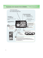
Explanation of the Operation Panel (FR-DU07)
Operation mode indication
PU: Lit to indicate PU operation mode.
EXT: Lit to indicate external operation mode.
NET: Lit to indicate network operation mode.
Rotation direction indication
FWD: Lit during forward rotation
REV: Lit during reverse rotation
On:
Forward/reverse operation
Flickering: When the frequency command is
not given even if the
forward/reverse command is given.
Unit indication
· Hz: Lit to indicate frequency.
· A: Lit to indicate current.
· V: Lit to indicate voltage.
(Flicker when the set frequency monitor is
displayed.)
Monitor indication
Lit to indicate monitoring mode.
No function
Monitor(4-digit LED)
Shows the frequency, parameter
number, etc.
Operation command
forward rotation
Operation command
reverse rotation
Setting dial
(Setting dial: Mitsubishi inverter
dial)
Stop operation
Alarms can be reset
Used to change the
frequency setting and
parameter values.
Used to set each setting.
If pressed during operation, monitor
changes as below;
Mode
switchover
Used to change
each setting mode.
Running
frequency
Output
current
Output
voltage
* Energy saving monitor is displayed when the
energy saving monitor of Pr. 52 is set.
Operation mode switchover
Used to switch between the PU and external operation mode.
When using the external operation mode (operation using a separately
connected frequency setting potentiometer and start signal), press this key to
light up the EXT indication. (Change the Pr.79 value to use the combined mode.)
PU: PU operation mode
EXT: External operation mode
19
*
Features
Basic operation
Operation mode switchover
and frequency flicker.
Frequency setting has been
written and completed!!
Output current monitor
Output voltage monitor
Terminal Connection
Diagram
Terminal Specification
Explanation
Value change
PU operation mode
(output frequency monitor)
Operation
Panel
(Example)
Explanations
of
Parameters
Display the current
setting
Parameter setting mode
Parameter and a setting value
flicker alternately.
Parameter write is completed!!
Parameter clear
All parameter
clear
Alarm clear
Options
Value change
Protective
Functions
(Example)
Instructions
Parameter setting
Parameter
List
Monitor/frequency setting
PU Jog operation mode
Outline
Dimension
Drawings
Standard
Specifications
Peripheral Devices
Why energy
savings?
At powering on (external operation mode)
Compatibility
[Operation for displaying alarm history]
Past eight alarms can be displayed.
(The latest alarm is ended by ".".)
is displayed.
Warranty
When no alarm history exists,
Inquiry
Alarm history
Motor
Parameter copy
20
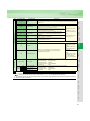
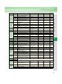
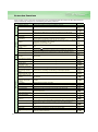
Parameter List
For simple variable-speed operation of the inverter, the initial setting of the parameters may be used as they are. Set the
necessary parameters to meet the load and operational specifications. Parameter setting, change and check can be made
from the operation panel (FR-DU07). For details of parameters, refer to the instruction manual.
POINT
Only simple mode parameters are displayed by the initial setting of Pr.160 User group read selection. Set Pr.160
User group read selection as required.
zSimple mode parameter
Parameter
Number
Name
Range
Increments
Initial Value
Refer to
page
0
Torque boost
0 to 30%
0.1%
6/4/3/2/1.5/1%*2
28
1
Maximum frequency
0 to 120Hz
0.01Hz
120/60Hz*1
28
2
Minimum frequency
0 to 120Hz
0.01Hz
0Hz
28
3
Base frequency
0 to 400Hz
0.01Hz
60Hz
28
4
Multi-speed setting (high speed)
0 to 400Hz
0.01Hz
60Hz
28
5
Multi-speed setting (middle speed)
0 to 400Hz
0.01Hz
30Hz
28
6
Multi-speed setting (low speed)
0 to 400Hz
0.01Hz
10Hz
28
7
Acceleration time
0 to 3600/ 360s
0.1/0.01s
5s/15s*3
28
8
Deceleration time
0 to 3600/ 360s
0.1/0.01s
10s/30s*3
28
0.01/0.1A*1
Rated inverter
output current
29
9
Electronic thermal O/L relay
0 to 500/ 0 to 3600A*1
60
Energy saving control selection
0, 4, 9
1
0
34
79
Operation mode selection
0, 1, 2, 3, 4, 6, 7
1
0
37
125
Terminal 2 frequency setting gain frequency
0 to 400Hz
0.01Hz
60Hz
39
126
Terminal 4 frequency setting gain frequency
0 to 400Hz
0.01Hz
60Hz
39
160
User group read selection
0, 1, 9999
1
9999
40
zExtended mode parameter
Remarks
⋅ The parameters marked with indicate simple mode parameters.
⋅ The shaded parameters in the table allow its setting to be changed during operation even if "0" (initial value) is set in Pr. 77
Parameter write selection.
Basic functions
Function
Parameters
0
1
2
3
4
5
6
7
8
DC Injection
Brake
9
Jog
operation
*1
*2
*3
*4
21
Name
Setting Range
Increments
Initial Value
Refer to
page
Torque boost
0 to 30%
0.1%
6/4/3/2/1.5/1%*2
28
Maximum frequency
0 to 120Hz
0.01Hz
120/60Hz*1
28
Minimum frequency
0 to 120Hz
0.01Hz
0Hz
28
Base frequency
0 to 400Hz
0.01Hz
60Hz
28
Multi-speed setting (high speed)
0 to 400Hz
0.01Hz
60Hz
28
Multi-speed setting (middle speed)
0 to 400Hz
0.01Hz
30Hz
28
Multi-speed setting (low speed)
0 to 400Hz
0.01Hz
10Hz
28
Acceleration time
0 to 3600/ 360s
0.1/0.01s
5s/15s*3
28
Deceleration time
0 to 3600/ 360s
0.1/0.01s
10s/30s*3
28
0.01/0.1A*1
Rated inverter
output current
29
Electronic thermal O/L relay
0 to 500/ 0 to 3600A*1
10
11
DC injection brake operation frequency
0 to 120Hz, 9999
0.01Hz
3Hz
29
DC injection brake operation time
0 to 10s
0.1s
0.5s
29
12
DC injection brake operation voltage
0 to 30%
0.1%
4/2/1%*4
29
13
14
15
Starting frequency
0 to 60Hz
0.01Hz
0.5Hz
29
Load pattern selection
0, 1
1
1
29
Jog frequency
0 to 400Hz
0.01Hz
5Hz
29
16
Jog acceleration/deceleration time
0 to 3600/360s
0.1/0.01s
0.5s
29
Differ according to capacities. (55K or less/75K or more)
Differ according to capacities. (0.75K/1.5K to 3.7K/5.5K, 7.5K/11K to 37K/45K, 55K/75K or more)
Differ according to capacities. (7.5K or less/11K or more)
Differ according to capacities. (7.5K or less/11K to 55K/75K or more)
60Hz
28
21
Acceleration/deceleration time
increments
0, 1
1
0
28
22
Stall prevention operation level
0 to 150%, 9999
0.1%
120%
30
23
Stall prevention operation level
compensation factor at double speed
0 to 200%, 9999
0.1%
9999
30
Multi-speed setting 4 speed to 7 speed
0 to 400Hz, 9999
0.01Hz
9999
28
28
Multi-speed input compensation
selection
0, 1
1
0
30
29
Acceleration/deceleration pattern
selection
0, 1, 2, 3
1
0
30
30
31
32
33
34
35
36
37
41
42
Regenerative function selection
0, 2/0, 1, 2*1
1
0
31
Frequency jump 1A
0 to 400Hz, 9999
0.01Hz
9999
31
Frequency jump 1B
0 to 400Hz, 9999
0.01Hz
9999
31
Frequency jump 2A
0 to 400Hz, 9999
0.01Hz
9999
31
Frequency jump 2B
0 to 400Hz, 9999
0.01Hz
9999
31
Frequency jump 3A
0 to 400Hz, 9999
0.01Hz
9999
31
Frequency jump 3B
0 to 400Hz, 9999
0.01Hz
9999
31
Speed display
0, 1 to 9998
1
0
31
Up-to-frequency sensitivity
0 to 100%
0.1%
10%
31
Output frequency detection
0 to 400Hz
0.01Hz
6Hz
31
Output frequency detection for reverse
rotation
0 to 400Hz, 9999
0.01Hz
9999
31
Second acceleration/deceleration time
0 to 3600/360s
0.1/0.01s
5s
28
Second deceleration time
0 to 3600/360s, 9999
0.1/0.01s
9999
28
Second torque boost
0 to 30%, 9999
0.1%
9999
28
Second V/F (base frequency)
0 to 400Hz, 9999
0.01Hz
9999
28
48
Second stall prevention operation
current
0 to 150%
0.1%
120%
30
49
Second stall prevention operation
frequency
0 to 400Hz, 9999
0.01Hz
0Hz
30
50
Second output frequency detection
0 to 400Hz
0.01Hz
30Hz
31
51
Second electronic thermal O/L relay
0 to 500A, 9999 /
0 to 3600A, 9999*1
0.01/0.1A*1
9999
29
DU/PU main display data selection
0, 5, 6, 8 to 14, 17, 20, 23
to 25, 50 to 57, 100
1
0
32
54
FM terminal function selection
1 to 3, 5, 6, 8 to 14, 17, 21,
24, 50, 52, 53
1
1
32
55
Frequency monitoring reference
0 to 400Hz
0.01Hz
60Hz
32
32
Frequency jump
43
Monitor functions
44
45
46
47
52
56
Current monitoring reference
0 to 500/0 to 3600A*1
0.01/0.1A*1
Rated inverter
output current
Automatic
restart
functions
Second functions
Frequency
detection
57
Restart coasting time
0, 0.1 to 5s, 9999/
0, 0.1 to 30s, 9999*1
0.1s
9999
33
58
Restart cushion time
0 to 60s
0.1s
1s
33
59
60
65
Remote function selection
0, 1, 2, 3
1
0
33
Energy saving control selection
0, 4, 9
1
0
34
Retry selection
0 to 5
1
0
34
*1
Differ according to capacities. (55K or less/75K or more)
Features
0.01Hz
Peripheral Devices
Why energy
savings?
1 to 400Hz
Standard
Specifications
28
Outline
Dimension
Drawings
20
Acceleration/deceleration reference
frequency
Terminal Connection
Diagram
Terminal Specification
Explanation
9999
Operation
Panel
28
0.1V
Parameter
List
0 to 1000V, 8888, 9999
Explanations
of
Parameters
29
Protective
Functions
0
120/60Hz*1
Options
Base frequency voltage
24 to 27
1
0.01Hz
Instructions
120 to 400Hz
Refer to
page
Motor
0, 2
High speed maximum frequency
Initial Value
Compatibility
MRS input selection
Increments
Warranty
17
18
19
Setting Range
Inquiry
Name
Acceleration
and
deceleration
times
Parameters
Multi-speed
Stall
setting
prevention
Function
22
Parameters
66
Retry
Function
0.01Hz
60Hz
30
1
0
34
0.1s
1s
34
0 to 10, 101 to 110
0 to 10s
Retry count display erase
0
1
0
34
Special regenerative brake duty *2
0 to 10%
0.1%
0%
31
Applied motor
0, 1, 2, 20
1
0
34
PWM frequency selection
0 to 15/0 to 6, 25*1
1
2
35
Analog input selection
0 to 7, 10 to 17
1
1
35
Input filter time constant
0 to 8
1
1
36
Reset selection/disconnected PU
detection/PU stop selection
0 to 3, 14 to 17
1
14
36
Alarm code output selection
0, 1, 2
1
0
36
Parameter write selection
0, 1, 2
1
0
36
Reverse rotation prevention selection
0, 1, 2
1
0
36
Operation mode selection
0, 1, 2, 3, 4, 6, 7
1
0
37
80
Motor capacity (simple magnetic flux
vector control)
0.4 to 55kW, 9999
/0 to 3600kW, 9999*1
0.01/0.1kW*1
9999
37
90
Motor constant (R1)
0 to 50Ω, 9999
/0 to 400mΩ, 9999*1
0.001Ω/
0.01mΩ*1
9999
37
100
101
102
103
104
105
106
107
108
109
117
118
119
120
121
122
123
V/F1 (first frequency)
0 to 400Hz, 9999
0.01Hz
9999
38
V/F1 (first frequency voltage)
0 to 1000V
0.1V
0V
38
V/F2 (second frequency)
0 to 400Hz, 9999
0.01Hz
9999
38
V/F2 (second frequency voltage)
0 to 1000V
0.1V
0V
38
V/F3 (third frequency)
0 to 400Hz, 9999
0.01Hz
9999
38
V/F3 (third frequency voltage)
0 to 1000V
0.1V
0V
38
V/F4 (fourth frequency)
0 to 400Hz, 9999
0.01Hz
9999
38
V/F4 (fourth frequency voltage)
0 to 1000V
0.1V
0V
38
V/F5 (fifth frequency)
0 to 400Hz, 9999
0.01Hz
9999
38
V/F5 (fifth frequency voltage)
0 to 1000V
0.1V
0V
38
PU communication station
0 to 31
1
0
38
PU communication speed
48, 96, 192, 384
1
192
38
PU communication stop bit length.
0, 1, 10, 11
1
1
38
PU communication parity check
0, 1, 2
1
2
38
Number of PU communication retries
0 to 10, 9999
1
1
38
PU communication check time interval
0, 0.1 to 999.8s, 9999
0.1s
9999
38
PU communication waiting time setting
0 to 150ms, 9999
1
9999
38
PU communication CR/LF presence/
absence selection
0, 1, 2
1
1
38
76
77
78
79
Simple
magnetic flux
vector control
Refer to
page
Retry waiting time
Adjustable 5 points V/F
Initial Value
Number of retries at alarm occurrence
67
68
69
70
71
72
73
74
75
PU connector
communication
Increments
0 to 400Hz
125
Terminal 2 frequency setting gain
frequency
0 to 400Hz
0.01Hz
60Hz
39
126
Terminal 4 frequency setting gain
frequency
0 to 400Hz
0.01Hz
60Hz
39
127
PID control automatic switchover
freqeuncy
0 to 400Hz, 9999
0.01Hz
9999
39
128
PID action selection
10, 11, 20, 21, 50, 51, 60,
61
1
10
39
129
130
131
132
133
134
PID proportional band
0.1 to 1000%, 9999
0.1%
100%
39
PID integral time
0.1 to 3600s, 9999
0.1s
1s
39
PID upper limit
0 to 100%, 9999
0.1%
9999
39
PID lower limit
0 to 100%, , 9999
0.1%
9999
39
PID action set point
0 to 100%, 9999
0.01%
9999
39
PID differential time
0.01 to 10.00s, 9999
0.01s
9999
39
PID operation
23
Setting Range
Stall prevention operation reduction
starting frequency
124
*1
*2
Name
Differ according to capacities. (55K or less/75K or more)
Setting can be made for the 75K or more.
138
0, 1
1
0
39
139
Automatic switchover frequency
between inverter and commercial powersupply operation
0 to 60Hz, 9999
0.01Hz
9999
39
140
Backlash acceleration stopping
frequency
0 to 400Hz
0.01Hz
1Hz
30
141
Backlash acceleration stopping time
0 to 360s
0.1s
0.5s
30
142
Backlash deceleration stopping
frequency
0 to 400Hz
0.01Hz
1Hz
30
143
Backlash deceleration stopping time
0 to 360s
0.1s
0.5s
30
1
4
31
1
0
40
144
Speed setting switchover
145
PU display language selection
0 to 7
148
149
150
Stall prevention level at 0V input.
0 to 150%
0.1%
120%
30
Stall prevention level at 10V input.
0 to 150%
0.1%
150%
30
Output current detection level
0 to 150%
0.1%
120%
40
Output current detection signal delay
time
0 to 10s
0.1s
0s
40
Zero current detection level
0 to 150%
0.1%
5%
40
Zero current detection time
0 to 1s
0.01s
0.5s
40
Voltage reduction selection during stall
prevention operation
0, 1
1
1
30
RT signal reflection time selection
0, 10
1
0
40
Stall prevention operation selection
0 to 31, 100, 101
1
0
30
OL signal output timer
0 to 25s, 9999
0.1s
0s
30
1
1
32
0.01Hz
9999
39
Current detection
0, 2, 4, 6, 8, 10, 102, 104,
106, 108, 110
151
152
153
154
155
156
157
158
AM terminal function selection
1 to 3, 5, 6, 8 to 14, 17, 21,
24, 50, 52, 53
159
Automatic switchover ON range
between commercial power-supply and
inverter operation
0 to 10Hz, 9999
160
User group read selection
0, 1, 9999
1
9999
40
161
Frequency setting/key lock operation
selection
0, 1, 10, 11
1
0
41
162
Automatic restart after instantaneous
power failure selection
0, 1, 10, 11
1
0
33
First cushion time for restart
0 to 20s
0.1s
0s
33
First cushion voltage for restart
0 to 100%
0.1%
0%
33
165
Stall prevention operation level for
restart
0 to 150%
0.1%
120%
33
Current
detection
166
Output current detection signal retention
time
0 to 10s, 9999
0.1s
0.1s
40
167
Output current detection operation
selection
0, 1
1
0
40
168
169
170
User
group
Cumulative
monitor
clear
Automatic
restart
functions
163
164
Parameter for manufacturer setting. Do not set.
Cumulative power meter clear
0, 10, 9999
1
9999
32
171
Operation hour meter clear
0, 9999
1
9999
32
172
User group registered display/batch
clear
9999, (0 to 16)
1
0
40
User group registration
0 to 999, 9999
1
9999
40
User group clear
0 to 999, 9999
1
9999
40
173
174
Features
39
Commercial power-supply operation
switchover selection at an alarm
Peripheral Devices
Why energy
savings?
39
0.5s
Standard
Specifications
1s
0.1s
Outline
Dimension
Drawings
0.1s
0 to 100s
Terminal Connection
Diagram
Terminal Specification
Explanation
0 to 100s
Waiting time at a start
Operation
Panel
MC switchover interlock time
136
137
Parameter
List
39
Explanations
of
Parameters
0
0, 1
Protective
Functions
1
Commercial power-supply switchover
sequence output terminal selection
135
Options
Refer to
page
Instructions
Initial Value
Motor
Increments
Compatibility
Setting Range
Warranty
Name
Inquiry
Parameters
PU
Backlash
measures
Commercial power
supply-inverter
switch-over
Function
24
Multi-speed
setting
Output terminal
function assignment
Input terminal function assignment
Function
Name
Setting Range
Increments
Initial Value
Refer to
page
178
STF terminal function selection
0 to 8, 10 to 12, 14, 16,
24, 25, 60, 62, 64 to 67,
9999
1
60
41
179
STR terminal function selection
0 to 8, 10 to 12, 14, 16,
24, 25, 61, 62, 64 to 67,
9999
1
61
41
180
181
182
183
RL terminal function selection
1
0
41
RM terminal function selection
1
1
41
1
2
41
1
3
41
1
4
41
RH terminal function selection
0 to 8, 10 to 12, 14, 16,
24, 25, 62, 64 to 67, 9999
RT terminal function selection
0 to 8, 10 to 12, 14, 16,
24, 25, 62 to 67, 9999
184
AU terminal function selection
185
186
187
188
189
190
191
192
193
194
195
JOG terminal function selection
1
5
41
CS terminal function selection
1
6
41
1
24
41
1
25
41
196
ABC2 terminal function selection
MRS terminal function selection
STOP terminal function selection
RES terminal function selection
RUN terminal function selection
SU terminal function selection
IPF terminal function selection
OL terminal function selection
FU terminal function selection
ABC1 terminal function selection
232 to 239 Multi-speed setting 8 speed to 15 speed
240
241
0 to 8, 10 to 12, 14, 16,
24, 25, 62, 64 to 67, 9999
1
62
41
0 to 5, 7, 8, 10 to 19, 25,
26, 45 to 47, 64, 70, 90 to
96, 98, 99, 100 to 105,
107, 108, 110 to 116, 125,
126, 145 to 147, 164, 170,
190 to 196, 198, 199, 9999
1
0
41
1
1
41
1
2
41
1
3
41
1
4
41
0 to 5, 7, 8, 10 to 19, 25,
26, 45 to 47, 64, 70, 90,
91, 94 to 96, 98, 99, 100 to
105, 107, 108, 110 to 116,
125, 126, 145 to 147, 164,
170, 190, 191, 194 to 196,
198, 199, 9999
1
99
41
1
9999
41
0.01Hz
9999
28
0 to 400Hz, 9999
Soft-PWM operation selection
0, 1
1
1
35
Analog input display unit switchover
0, 1
1
0
39
0 to 100%
0.1%
100%
35
0.1%
75%
35
242
243
Terminal 1 added compensation amount
(terminal 4)
0 to 100%
244
245
246
Cooling fan operation selection
0, 1
1
1
42
Rated slip
0 to 50%, 9999
0.01%
9999
42
Slip compensation time constant
0.01 to 10s
0.01s
0.5s
42
247
Constant-output region slip
compensation selection
0, 9999
1
9999
42
250
Stop selection
0 to 100s, 1000 to 1100s,
8888, 9999
0.1s
9999
42
251
Output phase failure protection
selection
0, 1
1
1
42
252
Override bias
0 to 200%
0.1%
50%
35
253
Override gain
0 to 200%
0.1%
150%
35
255
256
257
258
259
260
Life alarm status display
(0 to 15)
1
0
42
Inrush current limit circuit life display
(0 to 100%)
1%
100%
42
Control circuit capacitor life display
(0 to 100%)
1%
100%
42
Main circuit capacitor life display
(0 to 100%)
1%
100%
42
Main circuit capacitor life measuring
0, 1
1
0
42
PWM frequency automatic switchover
0, 1
1
1
35
Life check
Frequency
compensation
function
Slip
compensation
Terminal 1 added compensation amount
(terminal 2)
25
Parameters
0.01Hz
60Hz
43
Power-failure deceleration time 1
0 to 3600/ 360s
0.1/0.01s
5s
43
Power-failure deceleration time 2
0 to 3600/ 360s, 9999
0.1/0.01s
9999
43
Power failure deceleration time
switchover frequency
0 to 400Hz
0.01Hz
60Hz
43
Terminal 4 input selection
0, 1, 2
1
0
35
Monitor decimal digits selection
0, 1, 9999
1
9999
32
299
Rotation direction detection selection at
restarting
0, 1, 9999
1
9999
33
331
RS-485 communication station
0 to 31(0 to 247)
1
0
38
332
RS-485 communication speed
3, 6, 12, 24, 48, 96, 192,
384
1
96
38
333
RS-485 communication stop bit length
0, 1, 10, 11
1
1
38
334
RS-485 communication parity check
selection
0, 1, 2
1
2
38
335
RS-485 communication number of
retries
0 to 10, 9999
1
1
38
336
RS-485 communication check time
interval
0, 0.1 to 999.8s, 9999
0.1s
0s
38
337
RS-485 communication waiting time
setting
0 to 150ms, 9999
1
9999
38
338
Communication operation command
source
0, 1
1
0
44
339
340
341
342
343
495
496
Communication speed command source
0, 1, 2
1
0
44
Communication startup mode selection
0, 1, 2, 10, 12
1
0
37
RS-485 communication CR/LF selection
0, 1, 2
1
1
38
Communication EEPROM write selection
0, 1
1
0
38
Communication error count
1
0
38
Remote output selection
0, 1
1
0
44
Remote output data 1
0 to 4095
1
0
44
497
Remote output data 2
0 to 4095
1
0
44
503
Maintenance timer
0 (1 to 9998)
1
0
44
504
Maintenance timer alarm output set time
0 to 9998, 9999
1
9999
44
549
Protocol selection
0, 1
1
0
38
550
NET mode operation command source
selection
0, 1, 9999
1
9999
44
551
PU mode operation command source
selection
1, 2
1
2
44
Current average time
0.1 to 1.0s
0.1s
1s
44
Data output mask time
0.0 to 20.0s
0.1s
0s
44
0.01/0.1A*1
Rated inverter
current
44
Current
average
monitor
Remote output
RS-485 communication
267
268
269
Maintenance
266
PID
control
555
556
557
563
564
571
575
576
577
611
Parameter for manufacturer setting. Do not set.
Current average value monitor signal
output reference current
0 to 500/0 to 3600A*1
Energization time carrying-over times
0 to 65535
1
0
32
Operating time carrying-over times
0 to 65535
1
0
32
Holding time at a start
0.0 to 10.0s, 9999
0.1s
9999
29
Output interruption detection time
0 to 3600s, 9999
0.1s
1s
39
Output interruption detection level
0 to 400Hz
0.01Hz
0Hz
39
Output interruption release level
900 to 1100%
0.1%
1000%
39
Acceleration time at a restart
0 to 3600s, 9999
0.1s
5/15s*1
33
Features
0 to 120Hz, 9999
Peripheral Devices
Why energy
savings?
Subtraction starting frequency
263
264
265
Standard
Specifications
43
Outline
Dimension
Drawings
3Hz
Terminal Connection
Diagram
Terminal Specification
Explanation
0.01Hz
Operation
Panel
0 to 20Hz
Parameter
List
262
Explanations
of
Parameters
43
0, 1, 2
Subtracted frequency at deceleration
start
Protective
Functions
0
Power failure stop selection
Options
1
261
Instructions
Refer to
page
Motor
Initial Value
Compatibility
Increments
Warranty
Setting Range
Inquiry
Name
*1
Parameters
Communication
Power failure stop
Function
Differ according to capacities. (55K or less/75K or more)
26
Parameters
867
872
Calibration parameters
Energy saving monitor
Free
parameter
Regeneration
avoidance function
Function
Clear
parameters
PU
*1
*2
27
Name
Setting Range
Increments
Initial Value
Refer to
page
AM output filter
0 to 5s
0.01s
0.01s
32
Input phase failure protection selection
0, 1
1
0
42
882
Regeneration avoidance operation
selection
0, 1
1
0
45
883
Regeneration avoidance operation level
300 to 800V
0.1V
380V/760V*1
45
884
Regeneration avoidance at deceleration
detection sensitivity
0 to 5
1
0
45
885
Regeneration avoidance compensation
frequency limit value
0 to 10Hz, 9999
0.01Hz
6Hz
45
886
888
Regeneration avoidance voltage gain
0 to 200%
0.1%
100%
45
Free parameter 1
0 to 9999
1
9999
45
889
Free parameter 2
0 to 9999
1
9999
45
891
Cumulative power monitor digit shifted
times
0 to 4, 9999
1
9999
32
892
Load factor
30 to 150%
0.1%
100%
45
893
Energy saving monitor reference (motor
capacity)
0.1 to 55/0 to 3600kW*2
0.01/0.1kW*2
Inverter rated
capacity
45
894
Control selection during commercial
power-supply operation
0, 1, 2, 3
1
0
45
895
896
897
898
899
C0
(900)
C1
(901)
C2
(902)
C3
(902)
125
(903)
C4
(903)
C5
(904)
C6
(904)
126
(905)
C7
(905)
989
990
991
Pr.CL
ALLC
Er.CL
Power saving rate reference value
0, 1, 9999
Power unit cost
0 to 500, 9999
Power saving monitor average time
PCPY
1
9999
45
0.01
9999
45
0, 1 to 1000h, 9999
1
9999
45
Power saving cumulative monitor clear
0, 1, 10, 9999
1
9999
45
Operation time rate (estimated value)
0 to 100%, 9999
0.1%
9999
45
FM terminal calibration
46
AM terminal calibration
46
Terminal 2 frequency setting bias
frequency
0 to 400Hz
0.01Hz
0Hz
39
Terminal 2 frequency setting bias
0 to 300%
0.1%
0%
39
Terminal 2 frequency setting gain
frequency
0 to 400Hz
0.01Hz
60Hz
39
Terminal 2 frequency setting gain
0 to 300%
0.1%
100%
39
Terminal 4 frequency setting bias
frequency
0 to 400Hz
0.01Hz
0Hz
39
Terminal 4 frequency setting bias
0 to 300%
0.1%
20%
39
Terminal 4 frequency setting gain
frequency
0 to 400Hz
0.01Hz
60Hz
39
Terminal 4 frequency setting gain
0 to 300%
0.1%
100%
39
Parameter copy alarm release
10/100
1
10/100*2
-
PU buzzer control
0, 1
1
1
46
PU contrast adjustment
0 to 63
1
58
46
Parameter clear
0, 1
1
0
46
All parameter clear
0, 1
1
0
46
Alarm history clear
0, 1
1
0
46
Parameter copy
0, 1, 2, 3
1
0
46
The initial value differs according to the voltage class. (200V class / 400V class)
Differ according to capacities. (55K or less/75K or more)
Explanations of Parameters
Pr.2 Minimum frequency
Clamped at the
maximum frequency
Output frequency
(Hz)
ON
ON
ON
Frequency setting
0
Clamped at the (4mA)
minimum frequency
19, 47
5, 10V
(20mA)
Base frequency, voltage
Pr.3 Base frequency
Pr.19 Base frequency voltage
Speed 15
ON ON ON ON
RH
ON ON
ON
ON
RL
ON
REX
ON
ON
Time
ON ON
ON
ON
ON ON ON ON ON ON ON ON
*1
*1
Pr.47 Second V/F (base frequency)
z Used to adjust the inverter outputs (voltage, frequency) to the motor rating.
z When operating a standard motor, generally set the rated frequency of
the motor to Pr. 3 Base frequency. When running the motor using
commercial power supply-inverter switch-over operation, set Pr. 3 to
the same value as the power supply frequency.
z When you want to change the base frequency when switching multiple
motors with one inverter, use the Pr. 47 Second base frequency.
z Use Pr. 19 Base frequency voltage to set the base voltage (e.g. rated
motor voltage).
When turning RH, RM and RL off and REX on with "9999" set in Pr. 232
"multi speed setting (8 speed), the inverter operates at frequency set in
Pr. 6.
Pr. 7, 8
Pr.
20, 21, 44, 45
Pr.8 Deceleration time
Pr.20 Acceleration/deceleration reference frequency
Pr.21 Acceleration/deceleration time increments Pr.44 Second acceleration/deceleration time
Pr.45 Second deceleration time
z Used to set motor acceleration/deceleration time.
z Set a larger value for a slower speed increase/decrease or a
smaller value for a faster speed increase/decrease.
z Use Pr. 7 Acceleration time to set the acceleration time required to
reach Pr. 20 Acceleration/deceleration reference frequency from 0Hz.
z Use Pr. 8 Deceleration time to set the deceleration time required to
stop from the Pr. 20 Acceleration/deceleration reference frequency.
Pr.20
(60Hz)
Acceleration Pr.7
time
Running
frequency
Time
Deceleration Pr.8
time
Pr.21
Setting
Description
Increments:
0.1s
0
(initial value) Range:
0 to 3600s
Increments:
0.01s
1
Range:
0 to 360s
Increments and
setting range of
acceleration/
deceleration
time setting can
be changed.
Pr.19
indicates simple mode parameters and
Output frequency
(Hz)
Pr.3
Pr.47
Pr.
Standard
Specifications
Peripheral Devices
Why energy
savings?
Speed 14
Operation
Panel
Speed 13
RM
ON
ON
Pr.7 Acceleration time
Pr.2
Output voltage (V)
ON
Speed 11
Speed 12
Speed 8
Acceleration/deceleration time setting
Pr.1
Pr.18
Pr.
ON
RL
z Clamp the upper and lower limits of the output frequency.
z When you want to perform operation above 120Hz, set the upper
limit of the output frequency to Pr. 18 .
(When Pr. 18 is set, Pr. 1 automatically switches to the frequency
of Pr. 18. When Pr. 1 is set, Pr. 18 is automatically changed to the
frequency set in Pr. 1.)
Pr. 3 Pr.
ON
RM
You can limit the motor speed.
Speed 7
Time
RH
Pr.18 High speed maximum frequency
Speed 6
Parameter
List
Pr.1 Maximum frequency
Speed 2
(Middle speed)
Speed 3 Speed 4
(Low speed)
Speed 9
Explanations
of
Parameters
18
Maximum/minimum
frequency
Speed 10
Speed 5
Protective
Functions
Pr.
Speed 1
(High speed)
Options
Pr. 1, 2
If the initial set Pr. 71 value
is changed to the setting
for use with a constanttorque motor, the Pr. 0
setting changes to the
corresponding value in
above.
z The inverter operates at frequencies set in Pr. 4 when RH signal is
on, Pr. 5 when RM signal is on and Pr. 6 when RL signal is on.
z Frequency from speed 4 to speed 15 can be set according to the
combination of the RH, RM, RL and REX signals. Set the running
frequencies to Pr. 24 to Pr. 27, Pr. 232 to Pr. 239. (In the initial value
setting, speed 4 to 15 are unavailable.)
Instructions
0 Output frequency(Hz) Base
*
frequency
Can be used to change the preset speed in the parameter with
the contact signals.
Any speed can be selected by merely turning on-off the contact
signals (RH, RM, RL, REX signals).
Motor
Setting
range
←
←
2%*
←
←
←
Output
frequency (Hz)
Pr.0
Pr.46
6%
4%
3%
2%
1.5%
1%
Pr.25 Multi-speed setting (speed 5)
Pr.27 Multi-speed setting (speed 7)
Pr.233 Multi-speed setting (speed 9)
Pr.235 Multi-speed setting (speed 11)
Pr.237 Multi-speed setting (speed 13)
Pr.239 Multi-speed setting (speed 15)
indicates extended parameters. When setting parameters, refer to the instruction manual (applied) and understand instructions.
Compatibility
0.75K
1.5K to 3.7K
5.5K, 7.5K
11K to 37K
45K, 55K
75K or more
Output
voltage
When using
the constant
torque motor
Pr.24 Multi-speed setting (speed4)
Pr.26 Multi-speed setting (speed 6)
Pr.232 Multi-speed setting (speed 8)
Pr.234 Multi-speed setting (speed 10)
Pr.236 Multi-speed setting (speed 12)
Pr.238 Multi-speed setting (speed 14)
Warranty
Pr.0 Initial
Value
100%
Pr.6 Multi-speed setting (low speed)
Output frequency (Hz)
z Motor torque in the low-frequency range can be adjusted to the
load to increase the starting motor torque.
z The starting torque boost can be changed by switching terminal RT.
z When simple magnetic flux vector control is selected in Pr. 80, the
settings of Pr. 0 and Pr. 46 are invalid.
Pr.5 Multi-speed setting (middle speed)
Outline
Dimension
Drawings
Pr.4 Multi-speed setting (high speed)
You can compensate for a voltage drop in the low-frequency region
to improve motor torque reduction in the low-speed region.
Features
Multi-speed setting operation
Pr.46 Second torque boost
Inquiry
Pr.0 Torque boost
24 to 27, 232 to 239
Terminal Connection
Diagram
Terminal Specification
Explanation
Pr. 4 to Pr. 6 Pr.
Manual torque boost
46
Output frequency
(Hz)
Pr. 0 Pr.
28
Motor protection from overheat
(electronic thermal relay function)
Pr.9 Electronic thermal O/L relay Pr.51 Second electronic thermal O/L relay
Pr.
14
Pr. 14 Load pattern selection
Set the current of the electronic overcurrent protection to protect
the motor from overheat.This feature provides the optimum
protective characteristics, including reduced motor cooling
capability, at low speed.
z This function detects the overload (overheat) of the motor, stops
the operation of the inverter's output transistor, and stops the
output.
z Set the rated current [A] of the motor in Pr.9.
z When using a motor with an external thermal relay, etc., set “0” in
Pr. 9 to make the electronic thermal relay function invalid. (Note
that the output transistor protection of the inverter (E.THT)
functions.)
z When using the Mitsubishi constant-torque motor
1) Set “1” in Pr.71 .
(This provides a 100% continuous torque characteristic in the
low-speed range.)
2) Set the rated motor current in Pr. 9.
z When the RT signal is on, thermal protection is provided based on
the Pr. 51 setting.
Use this function when rotating two motors of different rated
currents individually by a single inverter. (When rotating two motors
You can select the optimum output characteristic (V/F
characteristic) for the application and load characteristics.
Setting “0”
For constant-torque load
Pr.10 DC injection brake operation frequency
Pr.12 DC injection brake operation voltage
100%
Pr.
Jog operation
15, 16
Pr.15 Jog frequency
Pr.16 Jog acceleration/deceleration time
You can set the frequency and acceleration/decelertion time for
jog operation. Jog operation can be performed from either the
outside or PU.
Can be used for conveyor positioning, test operation, etc.
Output
frequency
(Hz) Pr.20
Pr.15
Jog frequency
setting range
JOG signal
Forward
rotation STF
Pr.10 Operation
frequency
Output frequency (Hz)
Reverse
rotation STR
Time
Pr.12
Operation
voltage
Time
Pr.11 Operation time
Pr.12 Initial
Value
3.7K or less
5.5K to 7.5K
11K or more
75K or more
When
Using
the
Energy
Saving
Motor
←
←
2% *
3%
←
←
←
←
4%
4%
2%
1%
Pr.
17
Starting frequency
13, 571
Pr.13 Starting frequency
Setting range
Output
frequency
(Hz)
60
ON
ON
Logic selection of output stop
signal (MRS)
Pr.17 MRS input selection
Motor coasts
to stop
Setting value "0"
Output
stop
(Initial
value)
Inverter
Setting value "2"
Output
stop
MRS
SD (PC)
Time
MRS signal
ON
STF (STR)
signal
ON
Pr. 18
Refer to the section about Pr.1, Pr.2
Pr. 19
Refer to the section about Pr. 3.
Pr. 20, 21
Refer to the section about Pr.7, Pr.8
Pr.13
0
Forward
rotation
Pr.
ON
Pr.571 Holding time at a start
You can set the starting frequency and hold the set starting
frequency for a certain period of time.
Set these functions when you need the starting torque or want
smooth motor drive at a start.
29
Time
The inverter output can be shut off by the MRS signal. The logic
of the MRS signal can also be selected.
* If the Pr. 71 initial value is changed
to the setting for use with a
constant-torque motor, the Pr. 12
setting
changes
to
the
corresponding value in the above
table.
Pr.
Reverse
rotation
Pr.16
The DC injection brake can be operated at a motor stop to adjust
the stop timing and braking torque.
DC injection
brake
voltage
Forward
rotation
Pr.11 DC injection brake operation time
When
Using the
Mitsubish
Constant
Torque
Motor
Pr.3 Base frequency
Output frequency (Hz)
Pr.3 Base frequency
Output frequency (Hz)
DC injection brake
10 to 12
Setting “1” (initial value)
For variable-torque load
100%
together, use external thermal relays.)
Pr.
V/F pattern matching applications
Output voltage
51
Output voltage
Pr. 9 Pr.
Pr.571 setting time
Time
ON
indicates simple mode parameters and
Pr.
indicates extended parameters. When setting parameters, refer to the instruction manual (applied) and understand instructions.
Inverter
MRS
SD (PC)
Pr. 49 Setting
Definition
0 (initial value)
Without compensation
1
Pr.
With compensation
29, 140 to 143
Pr.29 Acceleration/deceleration pattern selection
Pr.141 Backlash acceleration stopping time
Pr.143 Backlash deceleration stopping time
Setting value "0"
[Linear acceleration
/ deceleration]
Time
Pr.23
Output frequency
(Hz)
Reduction ratio compensation
factor (%)
Stall prevention operation
level (%)
When Pr.23=9999
[S-pattern acceleration
/deceleration A]
fb
Time
Setting value "2"
400Hz
Output frequency (Hz)
Pr.66
[S-pattern acceleration
/deceleration B]
z Setting "9999" in Pr. 49 Second stall prevention operation frequency
and turning the RT signal on make Pr. 48 Second stall prevention
operation current valid.
z The stall prevention operation level from 0Hz to the output
frequency set in Pr. 49 can be set in Pr. 48.
Output frequency
(Hz)
f1
f2
Set frequency exceeds Pr. 49
Set
frequency
Pr.49
Stall
prevention
level
Set frequency is Pr. 49 or less
Pr.49
Set
frequency
Output
frequency
Time
Time
Pr. 22
used
Pr. 22
used
Pr. 48
used
Pr. 48
used
Setting value "3"
[Anti-backlash measure
function]
f2
Pr.142
f1
Pr.140
t1
Pr.141
Pr.
indicates simple mode parameters and
Time
Output
frequency (Hz)
Output
frequency
Output frequency (Hz)
Output
frequency (Hz)
Pr.
Pr.140 Backlash acceleration stopping frequency
Pr.142 Backlash deceleration stopping frequency
You can set the acceleration/deceleration pattern suitable for
application.
You can also set the backlash measures that stop acceleration/
deceleration once at the parameter-set frequency and time
during acceleration/deceleration.
Setting value "1"
Pr.22
Acceleration/ deceleration pattern
and back lash measures
t2
Pr.143
Time
z Linear acceleration/deceleration
(setting "0", initial value)
⋅ When the frequency is changed for
acceleration, deceleration, etc. in
inverter operation, the output
frequency is changed linearly (linear
acceleration/deceleration) to reach
the set frequency without straining
the motor and inverter.
z S-pattern acceleration/deceleration A
(setting "1")
⋅ For machine tool spindle
applications, etc.
Use when acceleration/deceleration
must be made in a short time to a
high-speed region of not lower than
base frequency.
z S-pattern acceleration/deceleration B
(setting "2")
⋅ For prevention of load shifting in
conveyor and other applications
Since acceleration/deceleration is
always made in an S shape from
current frequency (f2) to target
frequency (f1), this function eases
shock produced at acceleration/
deceleration and is effective for load
collapse prevention, etc.
z Backlash measures (setting "3", Pr.140
to Pr.143 )
⋅ To avoid backlash, acceleration/
deceleration is temporarily stopped.
Set the acceleration/deceleration
stopping frequency and time in Pr.
140 to Pr. 143.
indicates extended parameters. When setting parameters, refer to the instruction manual (applied) and understand instructions.
Features
Peripheral Devices
Why energy
savings?
Standard
Specifications
Outline
Dimension
Drawings
Terminal Connection
Diagram
Terminal Specification
Explanation
Pr. 28 Setting
Operation
Panel
By inputting the frequency setting compensation signal (terminal 1,
2), the speed (frequency) can be compensated for relative to the
multi-speed setting or the speed setting by remote setting function.
Parameter
List
Pr.28 Multi-speed input compensation selection
Explanations
of
Parameters
Input compensation of multispeed and remote setting
Protective
Functions
28
Options
Pr.
Instructions
Refer to the section about Pr.4 to Pr.6
Pr. 24 to 27
Motor
z Stall prevention
If the output current exceeds the limit value, the output frequency
of the inverter is automatically varied to reduce the output current.
Also the second stall prevention function can restrict the output
frequency range in which the stall prevention function is valid.
(Pr.49)
z Fast-response current limit
If the current exceeds the limit value, the output of the inverter is
shut off to prevent an overcurrent.
z Set in Pr. 22 the ratio of the output current to the rated inverter
current at which stall prevention operation will be performed.
Normally set this parameter to120% (initial value).
z When “9999” is set in Pr. 22, stall prevention operation level can be
changed by the signal to the auxiliary input terminal (terminal 1). For
the adjustment of bias/gain of analog signal, use Pr. 148 and Pr. 149.
z During high-speed operation above the rated motor frequency,
acceleration may not be made because the motor current does
not increase. If operation is performed in a high frequency range,
the current at motor lockup becomes smaller than the rated output
current of the inverter, and the protective function (OL) is not
executed if the motor is at a stop.
To improve the operating characteristics of the motor in this case,
the stall prevention level can be reduced in the high frequency
region. This function is effective for performing operation up to the
high speed region on a centrifugal separator etc. Normally, set
60Hz in Pr. 66 and 100% in Pr. 23.
z By setting "9999" (initial value) in Pr. 23 Stall prevention operation
level compensation factor at double speed, the stall prevention
operation level is constant at the Pr. 22 setting up to 400Hz.
z Stall prevention operation and fast response current restriction function
can be restricted according to the operation condition using Pr. 156.
Compatibility
This function monitors the output current and automatically changes
the output frequency to prevent the inverter from coming to an alarm
stop due to overcurrent, overvoltage, etc. It can also limit stall
prevention and fast-response current limit operation during
acceleration/deceleration, driving or regeneration.
The second stall prevention function is performed according to
the RT signal.
RT signal on ....... Stall level Pr. 48
RT signal off ....... Stall level Pr. 22
9999
Warranty
Pr.22 Stall prevention operation level
Pr.23 Stall prevention operation level compensation factor at double speed
Pr.48 Second stall prevention operation current
Pr.49 Second stall prevention operation frequency
Pr.66 Stall prevention operation reduction starting frequency
Pr.148 Stall prevention level at 0V input. Pr.149 Stall prevention level at 10V input.
Pr.154 Voltage reduction selection during stall prevention operation
Pr.156 Stall prevention operation selection
Pr.157 OL signal output timer
If the output frequency is less than the frequency set in
0.01Hz to 400Hz Pr. 49, the second stall prevention operation function is
activated. (during constant speed or deceleration)
Output frequency
(Hz)
Stall prevention operation
Operation
Second stall prevention function is not activated
Inquiry
22, 23, 48, 49, 66, 148, 149, 154, 156, 157
0 (initial value)
Set frequency
(Hz)
Pr.
30
30, 70
Pr.70 Special regenerative brake duty *
Pr.30 Regenerative function selection
z Use the high power factor converter (FR-HC) to reduce
harmonics, improve the power factor, or continuously use the
regenerative mode.
z For the 75K or more, use the brake unit MT-BU5 or BR5 when the
regenerative brake duty is need to be increased due to frequent
starts and stops. Use the high power factor converter MT-HC to
reduce harmonics, improve the power factor, or continuously use
the regenerative mode.
<55K or less>
Pr.30 Setting
Regeneration Unit
0 (initial value)
Brake unit (FR-BU, BU)
High power factor converter (FR-HC),
power regeneration common converter (FR-CV)
2
<75K or more>
Pr.30 Setting Pr.70 Setting *
0 (initial value)
1
Regeneration Unit
Not used
0%
Power regeneration converter (MT-RC)
10%
Brake unit (MT-BU5)
2
*2
Motor speed r/min conversion formula
....... Frequency × 120/number of motor poles (Pr. 144)
Machine speed conversion formula
...... Pr. 37 × frequency/60Hz
For Pr. 144 in the above formula, the value is “Pr. 144-100” when “102 to
110” is set in Pr. 144 and the value is “4” when Pr. 37=0 and Pr.144=0.
The increments for Hz are 0.01Hz, machine speed are 1m/min and r/min
are 1r/min
.
Pr.
41 to 43, 50
Pr.41 Up-to-frequency sensitivity
Pr.42 Output frequency detection
Pr.43 Output frequency detection for reverse rotation
Pr.50 Second output frequency detection
The inverter output frequency is detected and output at the
output signals.
z If the set frequency is considered as 100%, output frequency can
be adjusted between ±1% and ±100% with Pr. 41.
z This parameter can be used to ensure that the running frequency
has been reached to provide the operation start signal etc. for
related equipment.
Running frequency
High power factor converter (MT-HC)
* Pr.70 Special regenerative brake duty can be set for the 75K or more inverter.
Avoid mechanical resonance
points (frequency jump)
Pr.31 Frequency jump 1A
Pr.33 Frequency jump 2A
Pr.35 Frequency jump 3A
Pr.32 Frequency jump 1B
Pr.34 Frequency jump 2B
Pr.36 Frequency jump 3B
Frequency jump
Set frequency (Hz)
When it is desired to
avoid resonance
attributable to the
natural frequency of a
mechanical system,
these parameters allow
resonant frequencies to
be jumped.
Pr.36
Pr.35
Pr.34
Pr.33
Pr.32
Pr.31
z Up to three areas may be set, with the jump frequencies set to
either the top or bottom point of each area.
z The value set to 1A, 2A or 3A is a jump point and operation in the
jump zone is performed at these frequencies.
z Frequency jump is not performed if the initial value is set to "9999".
z During acceleration/deceleration, the running frequency within the
set area is valid.
Pr.
37, 144
z When the running speed monitor is selected, each monitor and
setting are determined according to the combination of Pr. 37 and
Pr. 144. (The units within the thick frame are the initial values.)
0
1 to
9998
31
Pr.
Pr. 144
Setting
Output
Frequency
Monitor
Set
Frequency
Monitor
Running
Speed
Monitor
Frequency
Setting
Parameter
Setting
0
Hz
Hz
r/min *1
Hz
2 to 10
Hz
Hz
r/min *1
Hz
102 to
110
r/min *1
r/min *1
r/min *1
r/min *1
0
Hz
Hz
Machine
speed *1
Hz
2 to 10
Machine
speed *1
Machine
speed *1
Machine
speed *1
Machine
speed *1
102 to
110
Hz
Hz
r/min *1
Hz
indicates simple mode parameters and
Pr.
Time
OFF
ON
OFF
Pr.50
Pr.42
Forward
rotation
Time
Pr.43
Pr.50
Reverse
rotation
Output
frequency OFF
FU
FU2
Pr. 44, 45
Pr.144 Speed setting switchover
You can change the PU (FR-DU07) monitor display or frequency
setting to motor speed or machine speed.
Adjustment
range Pr.41
z When the output frequency reaches or exceeds the setting of Pr.
42, the output frequency detection signal (FU) is output.
This function can be used for electromagnetic brake operation,
open signal, etc.
z When the detection frequency is set in Pr. 43, frequency detection
for reverse rotation use only can also be set. This function is
effective for switching the timing of electromagnetic brake
operation between forward rotation (rise) and reverse rotation
(fall) during vertical lift operation, etc.
z When outputting a frequency detection signal besides the FU
signal, set the detection frequency to Pr. 50 . The FU2 signal is
output when the output frequency reaches or exceeds the Pr. 50
setting.
Speed display and speed
setting
Pr.37 Speed display
Pr. 37
Setting
SU
(Hz)
31 to 36
Output frequency
Pr.
Detection of output frequency (SU,
FU, FU2 signal)
Output frequency
(Hz)
Pr.
*1
Selection of
regeneration unit
OFF
ON
OFF
ON
ON
OFF
ON
OFF
OFF
Refer to the section about Pr.7, Pr.8
Pr. 46
Refer to the section about Pr. 0.
Pr. 47
Refer to the section about Pr. 3.
Pr. 48, 49
Refer to the section about Pr. 22 and other
relevant parameters.
Pr. 50
Refer to the section about Pr. 41 and other
relevant parameters.
Pr. 51
Refer to the section about Pr. 9.
indicates extended parameters. When setting parameters, refer to the instruction manual (applied) and understand instructions.
3
Alarm display
Frequency setting
0.01Hz
5
*1
5
Running speed
1(r/min)
6
*1
6
Converter output
voltage
0.1V
8
*1
8
Regenerative brake
duty *5
0.1%
9
*1
9
Electronic thermal
relay function load
factor
0.1%
10
*1
10
0.01A/
0.1A*6
11
*1
11
Output current peak
value
Converter output
voltage peak value
Input power
Output power
Input terminal status
Output terminal
status
Option input
terminal status
Option output
terminal status
Load meter
Reference voltage
output
Cumulative
energization time *2
Actual operation
time *2, 3
Motor load factor
Cumulative power
Power saving effect
Cumulative saving
power
PID set point
PID measured value
PID deviation value
Pr.
0.1V
0.01kW/
0.1kW*6
0.01kW/
0.1kW*6
0/100
Pr.56
12
*1
12
13
*1
13
14
*1
14
*1
200V
class : 400V
400V
class : 800V
Rated inverter
power × 2
Rated inverter
power × 2
*1
×
55
56
×
57
0.1%
200V
class : 400V
400V
class : 800V
Pr.55
Value of Pr. 55
represented in
terms of Pr. 37
value
200V
class : 400V
400V
class : 800V
Brake duty set
in Pr. 30 and
Pr. 70
Electronic
thermal relay
function
operation level
17
17
Pr.56
21
20
1h
23
0.1%
0.01kWh/
0.1kWh *4, *6
24
24
25
Variable
according
to
parameters
50
50
51
0.1%
0.1%
0.1%
52
53
54
52
53
Pr.
Description
No function
0
When 1 or 2 decimal places (0.1 increments or 0.01
increments) are monitored, the decimal places are
dropped and the monitor displays an integer value (1
increments).
The monitor value of 0.99 or less is displayed as 0.
1
When 2 decimal places (0.01 increments) are
monitored, the 0.01 decimal place is dropped and the
monitor displays the first decimal place (0.1
increments).
When the monitor display digit is originally in 1
increments, it is displayed unchanged in 1
increments.
⋅ When Pr. 52 is set to "100", the set frequency monitor is displayed
during a stop and the output frequency monitor is displayed during
operation. (LED of Hz flickers during stop and is lit during
operation.)
Pr.52
0
During
operation/stop
Output
frequency
Output
current
Output
voltage
Alarm
display
100
Output frequency
200%
During stop
During
running
Set frequency
Output frequency
Output current
Alarm display
⋅ Using Pr. 867 , the output voltage response of the terminal AM can
be adjusted within the range 0 to 5s.
Pr.
55, 56
Change of the monitor output
from terminal FM and AM
Pr.56 Current monitoring reference
Set the full-scale value to output the output frequency monitor
value to terminal FM and AM.
Set the full-scale value to output the output current monitor value
to terminal FM and AM in Pr. 56.
Pulse speed(terminal FM)
Inverter
capacity
Output voltage(terminal AM)
2400
pulse/s
10VDC
1440
pulse/s
100%
100%
Output frequency
reference
Output current
reference
Features
Peripheral Devices
Why energy
savings?
Standard
Specifications
Output voltage
Pr.55 Frequency monitoring reference
1h
indicates simple mode parameters and
9999 (initial value)
Outline
Dimension
Drawings
0/100
Pr. 268 Setting
Pr.56
Terminal Connection
Diagram
Terminal Specification
Explanation
2
Operation
Panel
0.1V
0/100
Parameter
List
Output voltage
0.01Hz
0.01A/
0.1A*6
Explanations
of
Parameters
Output current
Protective
Functions
Output frequency
Increments
⋅ By setting “0” in Pr. 170, the cumulative power monitor can be
cleared.
⋅ You can check the numbers of cumulative energization time
monitor exceeded 65535h with Pr. 563 and the numbers of actual
operation time monitor exceeded 65535h with Pr. 564.
⋅ Writing "0" in Pr. 171 clears the actual operation time monitor.
Options
Types of Monitor
Pr.54
(FM)
Full Scale
Pr.158
Value
DU
PU main (AM)
LED
monitor Setting
0/100
1
Pr.55
⋅ The cumulative power monitor value digit can be shifted to the
right by the number set in Pr. 891.
Pr.55
400Hz
Pr.56
500A
Instructions
Pr.52 Parameter
Setting Value
*4
*5
*6
Warranty
The monitor to be displayed on the main screen of the operation
panel (FR-DU07) / parameter unit (FR-PU04) can be selected.
*3
Motor
Change of DU/PU monitor descriptions Cumulative monitor clear
Pr.52 DU/PU main display data selection Pr.54 FM terminal function selection
Pr.158 AM terminal function selection Pr.170 Cumulative power meter clear
Pr.171 Operation hour meter clear
Pr.268 Monitor decimal digits selection
Pr.563 Energization time carrying-over times
Pr.564 Operating time carrying-over times
Pr.867 AM output filter
Pr.891 Cumulative power monitor digit shifted times
Compatibility
52, 54, 158, 170, 171, 268, 563, 564, 867, 891
Selected by the parameter unit(FR-PU04)
The cumulative energization time and actual operation time are
accumulated from 0 to 65535 hours, then cleared, and accumulated again
from 0.
When the operation panel (FR-DU07) is used, up to 65.53 (65530h) is
displayed as 1h=0.001 and then accumulated from 0.
The actual operation time is not added up if the cumulative operation time
before power supply-off is less than 1h.
When using the parameter unit (FR-PU04), “kW” is displayed.
Setting can be made for the 75K or more.
The setting depends on the inverter capacity.(55K or less/75K or more)⋅
Pr.55
Pr.56
indicates extended parameters. When setting parameters, refer to the instruction manual (applied) and understand instructions.
400Hz
500A
Inquiry
Pr.
*1
*2
32
Pr.
When Pr. 162 = 0, 10 (with frequency search)
57, 58, 162 to 165, 299, 611
Instantaneous (power failure) time
Power supply
(R/L1,S/L2,T/L3)
Restart operation after instantaneous power failure / Flying start
Motor
speed N (r/min)
Inverter
output frequency
f (Hz)
Inverter
output voltage
E (V)
Pr.57 Restart coasting time
Pr.58 Restart cushion time
Pr.162 Automatic restart after instantaneous power failure selection
Pr.163 First cushion time for restart
Pr.164 First cushion voltage for restart Pr.165 Stall prevention operation level for restart
Pr.299 Rotation direction detection selection at restarting
Pr.611 Acceleration time at a restart
You can restart the inverter without stopping the motor in the
following cases.
⋅ when commercial power supply operation is switched to inverter
operation
⋅ when power comes back on after an instantaneous power failure
⋅ when motor is coasting at start
Pr.
Number
Setting Range
Description
1.5K or less..........0.5s,
2.2K to 7.5K.........1s,
0
0.1 to 5s/
0.1 to 30s *
9999 (initial value)
0 to 60s
0 (initial value)
1
162
163
10
11
0 to 20s
164
0 to 100%
165
0 to 150%
0
1
299
9999
0 to 3600s
611
9999
*
75K or more ........5.0s
The above times are coasting time.
Set the waiting time for inverter-triggered
restart after an instantaneous power
failure.
No restart
Set a voltage starting time at restart.
With frequency search
Without frequency search (reduced
voltage system)
Frequency search at every start
Reduced voltage system at every start
Set a voltage starting time at restart.
Consider using these parameters
according to the load (inertia moment,
torque) magnitude.
Consider the rated inverter current as
100% and set the stall prevention
operation level during restart operation.
Without rotation direction detection
With rotation direction detection
When Pr. 78 =0, the rotation direction is
detected.
When Pr. 78 =1,2, the rotation direction is
not detected.
Set the acceleration time to reach the set
frequency at restart.
Acceleration time for restart is the normal
acceleration time (e.g. Pr. 7).
The setting range varies according to the inverter capacity. (55K or less/
75K or more)
z When Pr. 162 = "1" or "11", automatic restart operation is
performed in a reduced voltage system, where the voltage is
gradually risen with the output frequency unchanged from prior to
an instantaneous power failure independently of the coasting
speed of the motor.
When Pr. 162 = 1, 11 (without frequency search)
Instantaneous (power failure) time
Power supply
(R/L1,S/L2,T/L3)
Motor speed N
(r/min)
Inverter
output frequency
f (Hz)
Inverter
output voltage
E (V)
Coasting time
Pr. 57 setting
Restart cushion
time
Pr. 58 setting
* The output shut off timing differs according
to the load condition.
Pr.
Remote setting function
59
Pr.59 Remote function selection
zEven if the operation panel is located away from the enclosure,
you can use contact signals to perform continuous variable-speed
operation, without using analog signals.
zBy merely setting this parameter, you can use the acceleration,
deceleration and setting clear functions of the motorized speed
setter (FR-FK).
CS
SD
RH, RM, RL signal
function
0 (initial value)
Multi-speed setting
1
Remote setting
Yes
2
Remote setting
No
3
Remote setting
No
(Turning STF/STR off
clears remotely-set
frequency.)
MC3
IM
MC
switchover
sequence
For use for only
automatic restart
after instantaneous
power failure or flying start,
short CS-SD in advance.
z When “0 (initial value) or 10” is set in Pr. 162, the inverter smoothly
starts after detecting the motor speed upon power restoration.
z Even when the motor is rotating in the opposite direction, the
inverter can be restarted smoothly as the direction of rotation is
detected. (You can select whether to make rotation direction
detection or not with Pr. 299 Rotation direction detection selection at
restarting. )
indicates simple mode parameters and
Pr.59 Setting
Pr.
Output frequency
(Hz)
MC1
R/L1 U
S/L2 V
T/L3 W
R1/L11
S1/L21
STF
CS
SD
Pr.
*
Description
MC2
33
Restart cushion
time (Pr. 58 setting)
Speed
detection time
* The output shut off timing differs according
to the load condition.
<Connection diagram>
MCCB
+
Acceleration time
at a restart
(Pr. 611 setting)
11K or more ........3.0s
57
58
Coasting
time (Pr.57)
*
Frequency setting
storage function
When Pr. 59 = 1
When Pr. 59 = 1, 2
When Pr. 59 = 3
When Pr. 59 = 2, 3
*
0Hz
Acceleration
(RH)
Deceleration
(RM)
Clear (RL)
Forward
rotation (STF)
Power supply
Time
ON
ON
ON
ON
ON
ON
ON
ON
ON
ON
ON
* External runnning frequency (other than multi-speed operation) or PU
running frequency
indicates extended parameters. When setting parameters, refer to the instruction manual (applied) and understand instructions.
z Set the number of retries at alarm occurrence in Pr. 67.
Retry function at alarm
occurrence
65, 67 to 69
Pr.65 Retry selection
Pr.68 Retry waiting time
Pr.67 Number of retries at alarm occurrence
Pr.69 Retry count display erase
If an alarm occurs, the inverter resets itself automatically to
restart. You can also select the alarm description for a retry.
When selection of automatic restart after instantaneous power
failure is selected (Pr. 57 Restart coasting time, restart operation is
performed at retry operation as at an instantaneous power
failure.)
z Use Pr. 65 to select the alarm to be activated for retries.
"z" indicates the alarms selected for retry.
Pr.65 Setting
Alarm Indication
for Retry
0
1
3
4
5
E.OC1
z
z
z
z
z
E.OC2
z
z
z
z
E.OC3
z
z
z
z
E.OV1
z
z
z
z
E.OV2
z
z
z
z
z
z
z
2
E.OV3
z
E.THM
z
E.THT
z
E.IPF
z
z
E.UVT
z
z
z
E.BE
z
z
z
z
E.OHT
z
E.OLT
z
z
E.OPT
z
z
E.OP1
z
z
E. PE
z
z
Pr. 70
Refer to the section about Pr. 30 and
other relevant parameters.
Pr.
Use the constant torque motor
(applied motor)
71
Pr.71 Applied motor
Setting of the used motor selects the thermal characteristic
appropriate for the motor.
Setting is necessary when using a constant-torque motor.
Thermal characteristic of the electronic thermal relay function
suitable for the motor is set.
Pr.71
Setting
0
(initial
value)
1
2
z
z
z
E.SER
z
z
E.ILF
z
z
Thermal Characteristic of the
Electronic Thermal Relay
Function
Thermal characteristics of a standard
motor
Motor
({: Motor used)
Constant
Standard
torque
(SF-JR,
(SF-HRCA,
etc.)
etc.)
{
Thermal characteristics of the Mitsubishi
constant-torque motor
Thermal characteristics of a standard
motor
Adjustable 5 points V/F
Mitsubishi standard motor SF-JR4P
(1.5kW or less)
Features
Peripheral Devices
Why energy
savings?
Standard
Specifications
{
{
{
z For the 5.5K and 7.5K, the Pr. 0 Torque boost and Pr. 12 DC injection
brake operation voltage settings are automatically changed
according to the Pr. 71 setting as follows.
Pr.71
Standard Motor Setting
0, 2, 20
Constant Torque Motor
Setting
1
Pr. 0
3%
2%
Pr. 12
4%
2%
Inquiry
E.PTC
E.CDO
Refer to the section about Pr. 65 and
other relevant parameters.
Pr. 67 to 69
20
E. GF
Refer to the section about Pr. 22 and other
relevant parameters.
Pr. 66
Outline
Dimension
Drawings
9
Optimum excitation control mode
The optimum excitation control mode is a control
system which controls excitation current to
improve the motor efficiency to maximum and
determines output voltage as an energy saving
system.
z Use Pr. 68 to set the waiting time from when an inverter alarm
occurs until a retry is made in the range 0 to 10s.
z Reading the Pr. 69 value provides the cumulative number of
successful restart times made by retry.
Terminal Connection
Diagram
Terminal Specification
Explanation
4
Energy saving operation mode
In the energy saving operation mode, the inverter
automatically controls the output voltage to
minimize the inverter output voltage during a
constant operation.
Operation
Panel
Normal operation mode
Parameter
List
Pr.
Description
Explanations
of
Parameters
0 (initial value)
101 to 110
Set the number of retries at alarm occurrence.
(The setting value of minus 100 is the number
of retries.)
An alarm output is provided during retry
operation.
Options
Pr. 60 Setting
Set the number of retries at alarm occurrence.
An alarm output is not provided during retry
operation.
Protective
Functions
Without a fine parameter setting, the inverter automatically
performs energy saving operation.
This inverter is optimum for fan and pump applications.
1 to 10
Instructions
Pr.60 Energy saving control
Description
No retry function
Motor
0 (initial value)
Compatibility
Pr. 67 Setting
Warranty
Pr. 60 Energy saving control selection
Pr.
indicates simple mode parameters and
Pr.
indicates extended parameters. When setting parameters, refer to the instruction manual (applied) and understand instructions.
34
Compensation
72, 240, 260
Carrier frequency and SoftPWM selection
Pr.72 PWM frequency selection
Pr.260 PWM frequency automatic switchover
Pr.240 Soft-PWM operation selection
You can change the motor sound.
Pr.
Number
72
240
Setting
Range
Description
0 to 15/
0 to 6, 25 *
You can change the PWM carrier frequency. The
setting displayed is in [kHz].
Note that 0 indicates 0.7kHz, 15 indicates
14.5kHz and 25 indicates 2.5kHz.
0
Soft-PWM is invalid
1
When "0 to 5" ("0 to 4" for the 75K or more) is set
in Pr. 72, Soft-PWM is valid
0
PWM carrier frequency is constant independently
of load. When the carrier frequency is set to 3kHz
or more (Pr. 72 ≥ 3), perform continuous operation
at less than 85% of the rated inverter current.
260
1
Decreases PWM carrier frequency automatically
when load increases.
* The setting range varies according to the inverter capacity. (55K or less/75K
or more).
(Note)When Pr. 260="1 (initial value)", if continuous operation is performed at
85% or more of the rated inverter current with Pr. 72 value set to “3”
(3kHz) or more, the carrier frequency is automatically reduced. This
may cause the motor noise to increase.
Pr.
Method
0
1
(Initial
value)
2
3
4
5
6
7
10
11
12
13
14
15
16
0 to 10V 0 to ±10V
×
0 to ±5V
0 to ±5V
0 to 10V
0 to 5V
×
×
0 to 10V
0 to 5V
73, 242, 243, 252, 253, 267
0 to ±5V
⋅ A compensation signal can be added to the main speed
setting for synchronous operation, etc.
Output frequency
When voltage across
terminals 2-5 is 2.5V
(5V)
0
Output frequency
When voltage across
terminals 2-5 is 2.5V
(5V)
+2.5V +5V Terminal 1
(+5V) (+10V)
When voltage
across terminals
2-5 is 0V
Terminal 1
added
compensation
When the AU
signal is off
×
Terminal 1
added
compensation
Terminal 2
override
Terminal 1
added
compensation
4 to 20mA 0 to ±5V
indicates simple mode parameters and
Terminal 2
override
Pr.
Reverse rotation
(a) When Pr. 73 setting is 0 to 5
Not function
(Indicates that
a frequency
command
signal of
negative
polarity is not
accepted. )
Function
+2.5V
(+5V)
+5V Terminal 1
(+10V)
Forward rotation
Reverse rotation
Forward rotation
Method
0
STF
Forward rotation
(b) When Pr. 73 setting is 10 to 15
⋅ The terminal 1 (frequency setting auxiliary input) signal is added
to the main speed setting signal of the terminal 2 or 4.
(2) Override function (Pr.252, Pr.253)
⋅ When an override is selected, the terminal 1 or 4 is used for
the main speed setting and the terminal 2 for the override
signal. (When the main speed of the terminal 1 or terminal 4
is not input, compensation by the terminal 2 is invalid.)
200
Compensation
0
0 to 10V 0 to ±10V
1
0 to 5V 0 to ±10V
(Initial
value)
2
0 to 10V 0 to ±5V
3
0 to 5V 0 to ±5V
4
0 to 10V 0 to ±10V
5
0 to 5V 0 to ±5V
6
4 to 20mA 0 to ±10V
7
4 to 20mA 0 to ±5V
10
0 to 10V 0 to ±10V
11
0 to 5V 0 to ±10V
12
0 to 10V 0 to ±5V
13
0 to 5V 0 to ±5V
14
0 to 10V 0 to ±10V
15
0 to 5V 0 to ±5V
16
4 to 20mA 0 to ±10V
-5V -2.5V
(-10V) (-5V)
Forward rotation
STF
Input Terminal
Pr. 73 Terminal 2 Terminal 1
and
Terminal 4 Input
Polarity Reversible
Setting
Input
Input
Compensation
Function
Terminal 2
override
Terminal 1
added
compensation
×
(1) Added compensation (Pr.242, Pr.243)
-5V -2.5V
(-10V) (-5V)
z You can select the function that switches between forward rotation
and reverse rotation according to the analog input polarity, the
override function and the input signal specifications.
z For the terminals 1, 2, 4 used for analog input, voltage input (0 to
5V, 0 to 10V) or current input (4 to 20mA) can be selected.
z The additional compensation and fixed ratio of analog
compensation (override) using terminal 2 as an auxiliary input can
be made to multi-speed operation or the speed setting signal
(main speed) of the terminal 2 or terminal 4.
(
indicates the main speed setting)
Pr.
Terminal 1
added
compensation
0 to ±10V
×
17
Analog input selection
35
When the AU
signal is on
0 to ±10V According to the
0 to ±5V
Pr. 267 setting
(Initial value)
0 to ±10V
1:0 to 5V
0 to ±10V
2:0 to 10V
0 to ±5V
0 to ±5V
×
When voltage
across terminals
2-5 is 0V
Pr.73 Analog input selection
Pr.242 Terminal 1 added compensation amount (terminal 2)
Pr.243 Terminal 1 added compensation amount (terminal 4)
Pr.252 Override bias
Pr.253 Override gain
Pr.267 Terminal 4 input selection
17
Not function
Terminal 1
(Indicates that
added
compensation a frequency
command
signal of
negative
Terminal 2
polarity is not
override
accepted. )
0 to ±10V
Pr.252
Pr.253
Override value (%)
Pr.
Input Terminal
Pr. 73 Terminal 2 Terminal 1
and
Terminal 4 Input
Polarity Reversible
Setting
Input
Input
Compensation
150
Initial value
(50% to 150%)
100
50
0
0V
2.5V
5V
(5V)
(10V)
Voltage across terminals 2-5
⋅ When an override is selected, the terminal 1 or 4 is used for the
main speed setting and the terminal 2 for the override signal (50%
to 150% at 0 to 5V or 0 to 10V). (When the main speed of the
terminal 1 or 4 is not input, compensation by the terminal 2 is
invalid.)
⋅ When Pr. 22 Stall prevention operation level = "9999", the value of
the terminal 1 is as set to the stall prevention operation level.
indicates extended parameters. When setting parameters, refer to the instruction manual (applied) and understand instructions.
0
Reset input normally
enabled.
1
Reset input enabled
only when the protective
function is activated.
2
Reset input normally
enabled.
3
Reset input enabled
only when the protective
function is activated.
14
(initial
value)
15
Reset input normally
enabled.
Reset input enabled
only when the protective
function is activated.
16
Reset input normally
enabled.
17
Reset input enabled
only when the protective
function is activated.
Disconnected
PU Detection
If the PU is
disconnected,
operation will be
continued as-is.
When the PU is
disconnected,
the inverter
output is shut
off.
If the PU is
disconnected,
operation will be
continued as-is.
When the PU is
disconnected,
the inverter
output is shut
off.
Alarm code output at alarm occurrence only (Refer to
the following table)
z The following table indicates alarm codes to be output. (0: output
transistor off, 1: output transistor on)
IPF
OL
FU
Normal *
0
0
0
0
0
E.OC1
0
0
0
1
1
E.OC2
0
0
1
0
2
E.OC3
0
0
1
1
3
E.OV1 to E.OV3
0
1
0
0
4
E.THM
0
1
0
1
5
Pressing
E.THT
0
1
1
0
6
decelerates the
motor to a stop only
in the PU operation
mode.
E.IPF
0
1
1
1
7
E.UVT
1
0
0
0
8
E.FIN
1
0
0
1
9
E.BE
1
0
1
0
A
PU Stop
Selection
Output of Output Terminals
Alarm Code
E. GF
1
0
1
1
B
E.OHT
1
1
0
0
C
E.OLT
1
1
0
1
D
Pressing
E.OPT
1
1
1
0
E
decelerates the
motor to a stop in
any of the PU,
external and
communication
operation modes.
E.OP1
1
1
1
0
E
Other than the
above
1
1
1
1
F
* When Pr. 76 = "2", the output terminals output the signals assigned to Pr.
190 to Pr. 196.
z Reset selection
⋅ You can select the operation timing of reset function (RES
signal, reset command through communication) input
z Disconnected PU detection
⋅ This function detects that the PU (FR-DU07/FR-PU04) has
been disconnected from the inverter for longer than 1s and
causes the inverter to provide an alarm output (E.PUE) and
come to an alarm stop.
z PU stop selection
⋅ In any of the PU operation, external operation and network
operation modes, the motor can be stopped by pressing
Pr.
77
Prevention of parameter rewrite
You can select whether write to various parameters can be
performed or not. Use this function to prevent parameter values
from being rewritten by misoperation.
Pr. 77 Setting
0 (initial value)
of
Pr.
78
Description
Write is enabled only during a stop
1
Parameter write is not enabled.
2
Parameter write is enabled in any operation
mode regardless of operation status.
Prevention of reverse rotation of
the motor
Pr.78 Reverse rotation prevention selection
This function can prevent reverse rotation fault resulting from the
incorrect input of the start signal.
Pr.78 Setting
0 (initial value)
indicates simple mode parameters and
Pr.
Peripheral Devices
Why energy
savings?
Pr.77 Parameter write selection
the PU.
Pr.
Standard
Specifications
2
SU
You can select the reset input acceptance, disconnected PU
(FR-DU07) connector detection function and PU stop function.
Reset Selection
With alarm code output (Refer to the following table)
Operation Panel
Indication
(FR-DU07)
Pr.75 Reset selection/disconnected PU detection/PU stop selection
Pr.75
Setting
1
Outline
Dimension
Drawings
Reset selection, disconnected PU
detection
Description
Without alarm code output
Terminal Connection
Diagram
Terminal Specification
Explanation
75
0 (initial value)
Instructions
Pr.
Pr.76 Setting
Motor
z Valid for eliminating noise of the frequency setting circuit.
z Increase the filter time constant if steady operation cannot be
performed due to noise.
A larger setting results in slower response. (The time constant can
be set between approximately 10ms to 1s with the setting of 0 to 8.)
Operation
Panel
At alarm occurrence, its description can be output as a 4-bit
digital signal from the open collector output terminals.
The alarm code can be read by a programmable controller, etc.,
and its corrective action can be shown on a display, etc.
Parameter
List
The time constant of the primary delay filter relative to external
frequency command (analog input (terminal 1, 2, 4) signal) can
be set.
Explanations
of
Parameters
Pr.76 Alarm code output selection
Protective
Functions
Pr.74 Input filter time constant
Features
Output function of alarm code
76
Options
Pr.
Compatibility
Noise elimination at the analog
input
Warranty
74
Description
Both forward and reverse rotations allowed
1
Reverse rotation disabled
2
Forward rotation disallowed
indicates extended parameters. When setting parameters, refer to the instruction manual (applied) and understand instructions.
Inquiry
Pr.
36
Pr. 79 Pr.
340
Operation mode selection
Pr.79 Operation mode selection Pr.340 Communication startup mode selection
zUsed to select the operation mode of the inverter.
You can freely change between operation by external signal
(external operation), operation by PU (FR-DU07) (PU operation),
operation by combination of PU operation and external operation
(external/PU combined operation) and network operation (when
RS-485 terminals or a communication option is used).
Pr.79
Setting
LED Indication
:Off
:On
Description
External/PU switchover mode ( Press
0
(initial
value)
1
2
to switch between the PU and
external operation mode.)
External operation mode at power-on
Fixed to PU operation mode
Fixed to external operation mode
Operation can be performed by switching
between the external and Net operation
mode.
PU
3
4
EXT
Pr.79
Setting
0
(initial
value)
As set in Pr. 79.
NET
PU
EXT
NET
PU
EXT
NET
External operation
mode
PU
EXT
1, 2 *1
7
1
PU operation mode
2
NET operation mode
Can be switched to external,
PU or NET operation mode *2
Fixed to PU operation mode
7
X12(MRS)signal OFF
.. External operation
mode
0
NET operation mode
1
PU operation mode
Can be switched to external
or NET operation mode
Switching to PU operation
mode disabled
Operation mode switching
disabled
Can be switched to external,
PU or NET operation mode
with operation continued
Can be switched to external,
PU or NET operation mode *2
Fixed to external operation
mode (Forcibly switched to
external operation mode.)
Can be switched to PU or
NET operation mode *3
Fixed to PU operation mode
2
NEToperation mode
External/PU combined
operation mode
Fixed to NET operation mode
Operation mode switching is
disallowed
NET operation mode
Can be switched to PU or
NET operation mode with
operation continued *3
3, 4
6
NET
EXT
EXT
NET
3, 4
6
Fixed to external operation
mode (Forcibly switched to
external operation mode.)
The Pr. 340 setting "2" or "12" is mainly used for communication
operation using the inverter RS-485 terminals.
When a value other than "9999" (selection of automatic restart after
instantaneous power failure) is set in Pr. 57 Restart coasting time, the
inverter will resume the same operation state which was in before after
power has been restored from an instantaneous power failure.
The operation mode cannot be switched directly between the PU
operation mode and network operation mode.
Operation mode can be changed between the PU operation mode and
7
*1
EXT
NET
PU
EXT
NET
NET operation
mode
EXT
NET
PU operation mode
PU
EXT
NET
External operation
mode
PU
EXT
NET
NET operation mode
*1
NET
External operation
mode
External/PU combined
operation mode
X12 (MRS) signal ON
.. NET operation mode
10, 12
PU
PU
External operation mode (PU operation
interlock)
X12 signal ON
Operation mode can be switched to the
PU operation mode.
(output stop during external operation)
X12 signal OFF
Operation mode can not be switched to
the PU operation mode.
NET operation mode
NET operation
mode
PU
6
0
Operation Mode
Switchover
PU operation mode
PU operation mode
Switch-over mode
Switch among PU operation, external
operation, and NET operation while
keeping the same operation status.
Operation mode at
Power On, Power
Restoration, Reset
Pr. 340
Setting
External operation
mode
PU
External/PU combined operation mode 1
Running frequency
Start signal
PU (FR-DU07 /
FR-PU04) setting
or external signal
External signal
input (multi-speed
input (terminal STF,
setting, across
STR)
terminals 4-5 (valid
when AU signal
turns on))
External/PU combined operation mode 2
Running frequency
Start signal
Input from the PU
External signal
(FR-DU07 / FRinput (terminal 2, 4, PU04)
1, Jog, multi-speed
setting, etc)
(
,
)
z Specify operation mode at power on (Pr.340)
⋅ When power is switched on or when power comes back on after
instantaneous power failure, the inverter can be started up in the
network operation mode.
After the inverter has started up in the network operation mode,
parameter write and operation can be performed from a program.
Set this mode for communication operation using the inverter RS485 terminals or communication option.
⋅ You can set the operation mode at power on (reset) according
to the Pr. 79 and Pr. 340 settings.
*2
*3
External operation
mode
network operation mode with
key of the operation panel (FR-
DU07) and X65 signal.
Pr.
80, 90
Simple magnetic flux vector
control
Pr.80 Motor capacity (simple magnetic flux vector control)
Pr.90 Motor constant (R1)
Providing optimum excitation to the motor can also produce high
torque in a low-speed region. (simple magnetic flux vector control)
⋅ Set the used motor capacity (equal to or one rank higher than the
inveter capacity) in Pr. 80.
⋅ The number of motor poles should be any of 2, 4 and 6 poles.
⋅ Single-motor operation (one motor for one inverter)
⋅ Wiring length from inverter to motor should be within 30m.
⋅ When simple magnetic flux vector control is not used, set "9999"
(initial value) in Pr. 80.
⋅ For Pr. 90 Motor constant (R1), normally setting is not necessary.
When you need more torque under simple magnetic flux vector
control for other manufacturer's motor, set the motor primary
resistance value (R1) for
connection in Pr. 90
37
Pr.
indicates simple mode parameters and
Pr.
indicates extended parameters. When setting parameters, refer to the instruction manual (applied) and understand instructions.
120
334
Voltage
2bit
10
1bit
11
2bit
V/F1
V/F2
0
Without parity check
With odd parity check
2 (initial value)
With even parity check
9999
⋅ Adjustable 5 points V/F will not function under simple magnetic
flux vector control.
⋅ When Pr. 19 Base frequency voltage = "8888" or "9999", Pr. 71 cannot be
set to "2". To set Pr. 71 to "2", set the rated voltage value to Pr. 19
⋅ When the frequency values of the points are the same, a write
inhibit error (
) occurs.
⋅ Set the points (frequencies, voltages) of Pr. 100 to Pr. 109 within
the ranges of Pr. 3 Base frequency and Pr. 19 Base frequency voltage .
⋅ When “2” is set in Pr. 71, Pr. 47 Second V/F (base frequency) will not
function.
⋅ When “2” is set in Pr. 71, thermal characteristic of the electronic
thermal relay function changes to thermal characteristics of a
standard motor.
122
336
0.1 to 999.8s
9999 (initial value)
*1
117 to 124, 331 to 337, 341 to 343, 549
0 to 150ms
9999 (initial value)
124
341
*2
Set the permissible number of retries at
occurrence of a data receive error. If the
number of consecutive errors exceeds the
permissible value, the inverter will come to
an alarm stop.
If a communication error occurs, the
inverter will not come to an alarm stop.
No PU connector communication
Communication with RS-485 terminal can
be made, but the inverter will come to an
alarm stop in the NET operation mode.
0
123
337
7bit
1
Frequency
Base frequency
V/F Characteristic
Pr.3
8bit
0
0 to 10
121
335
V/F3
Torque boost
Pr.0
0
Set the interval of communication check
time.
If a no-communication state persists for
longer than the permissible time, the
inverter will come to an alarm stop.
No communication check
Set the waiting time between data
transmission to the inverter and response.
Set with communication data.
Without CR/LF
1 (initial value)
2
With CR
With CR/LF
When making communication through Modbus-RTU protocol with the RS485 terminals, the setting range of Pr. 331 within parenthesis is applied.
The values in parenthesis are added to the setting range of Pr. 332.
Communication initial setting
(2) Communication EEPROM write selection (Pr.342)
Pr.117 PU communication station
Pr.118 PU communication speed
Pr.119 PU communication stop bit length. Pr.120 PU communication parity check
Pr.121 Number of PU communication retries Pr.122 PU communication check time interval
Pr.123 PU communication waiting time setting
Pr.124 PU communication CR/LF presence/absence selection
Pr.331 RS-485 communication station
Pr.332 RS-485 communication speed
Pr.333 RS-485 communication stop bit length
Pr.334 RS-485 communication parity check selection
Pr.335 RS-485 communication number of retries Pr.336 RS-485 communication check time interval
Pr.337 RS-485 communication waiting time setting
Pr.341 RS-485 communication CR/LF selection Pr.342 Communication EEPROM write selection
Pr.343 Communication error count
Pr.549 Protocol selection
(3) Modbus-RTU communication specifications (Pr.343,
Pr.549)
(1)
Initial settings and specifications of RS-485
communication (Pr.117 to Pr.124, Pr.331 to Pr.337, Pr.341)
Used to perform required settings for RS-485 communication
between the inverter and personal computer.
zThere are two different communications: communication
using the PU connector of the inverter and communication
using the RS-485 terminals.
zYou can perform parameter setting, monitor, etc. using the
Mitsubishi inverter protocol or Modbus-RTU protocol.
zTo make communication between the personal computer and
inverter, initialization of the communication specifications
must be made to the inverter.
Data communication cannot be made if the initial settings
are not made or there is any setting error.
Pr.
indicates simple mode parameters and
Pr.
Parameters written via the inverter's PU connector or RS-485
terminals or from the communication option can be written to
the RAM. When performing parameter change frequently, set
"1" in Pr. 342.
* The Modbus-RTU protocol is valid for only communication from the RS-485
terminals.
Pr. Number
343
549
Setting
Range
Description
Display the number of communication
errors during Modbus-RTU communication.
Reading only
0
(initial value)
1
Mitsubishi inverter (computer link) protocol
Modbus-RTU protocol
indicates extended parameters. When setting parameters, refer to the instruction manual (applied) and understand instructions.
Features
Peripheral Devices
Why energy
savings?
Data length
Standard
Specifications
1 (initial value)
V/F5
V/F4
Pr.
1bit
Outline
Dimension
Drawings
119
333
0
Terminal Connection
Diagram
Terminal Specification
Explanation
Stop bit length
A dedicated V/F pattern can be made by freely setting the V/F
characteristic between a startup and the base frequency and
base voltage under V/F control (frequency voltage/frequency).
Possible to set the torque pattern that is optimum for the
machine’s characteristic
Base frequency
voltage
Pr.19
Set the communication speed.
The setting value × 100 equals the
communication speed.
For example, the communication speed is
19200bps when the setting value is "192".
Operation
Panel
48, 96, 192, 384
(3, 6, 12, 24) *2
Pr.101 V/F1 (first frequency voltage)
Pr.103 V/F2 (second frequency voltage)
Pr.105 V/F3 (third frequency voltage)
Pr.107 V/F4 (fourth frequency voltage)
Pr.109 V/F5 (fifth frequency voltage)
Parameter
List
Pr.100 V/F1 (first frequency)
Pr.102 V/F2 (second frequency)
Pr.104 V/F3 (third frequency)
Pr.106 V/F4 (fourth frequency)
Pr.108 V/F5 (fifth frequency)
Explanations
of
Parameters
118
332
Adjustable 5 points V/F
Protective
Functions
Specify the inverter station number.
Set the inverter station numbers when two
or more inverters are connected to one
personal computer.
Options
0 to 31
(0 to 247) *1
Instructions
117
331
100 to 109
Motor
Description
Compatibility
Setting Range
Warranty
Pr.
Pr.
Number
Inquiry
.
38
Pr. 125 Pr. 126 Pr.
241, C2(902) to C7(905)
Analog input frequency change and voltage, current input and
frequency adjustment (calibration)
Pr.125 Terminal 2 frequency setting gain frequency
Pr.126 Terminal 4 frequency setting gain frequency
Pr. 241 Analog input display unit switchover
C2(Pr.902) Terminal 2 frequency setting bias frequency
C3(Pr.902) Terminal 2 frequency setting bias C4(Pr.903) Terminal 2 frequency setting gain
C5(Pr.904) Terminal 4 frequency setting bias frequency
C6(Pr.904) Terminal 4 frequency setting bias C7(Pr.905) Terminal 4 frequency setting gain
z You can set the magnitude (slope) of the output frequency as
desired in relation to the frequency setting signal (0 to 5VDC, 0 to
10V or 4 to 20mA).
(1)
Change the frequency at maximum analog input.
(Pr.125, Pr.126)
Set a value in Pr. 125 (Pr. 126) when changing only the
frequency setting (gain) of the maximum analog input power
(current). (C2 (Pr. 902) to C7 (Pr. 905) setting need not be
changed)
Output frequency
(Hz)
Initial value
Pr.
Pr.127 PID control automatic switchover freqeuncy
Pr.128 PID action selection
Pr.129 PID proportional band
Pr.130 PID integral time
Pr.131 PID upper limit
Pr.132 PID lower limit
Pr.133 PID action set point
Pr.134 PID differential time
Pr.575 Output interruption detection time
Pr.576 Output interruption detection level Pr.577 Output interruption release level
The inverter can be used to exercise process control, e.g. flow
rate, air volume or pressure.
The terminal 2 input signal or parameter setting is used as a set point
and the terminal 4 input signal used as a feedback value to constitute
a feedback system for PID control.
⋅ Pr.128 ="10, 11" (Deviation value signal input)
Inverter circuit
Set point
To outside
Manipulated Motor
variable
IM
Feedback signal (measured value)
Kp: Proportionality constant Ti: Integral time S: Operator Td: Differential time
⋅ Pr.128 ="20, 21" (Measured value input)
Inverter circuit
Pr. 133 or
terminal 2
PID operation
+-
Kp 1+ Ti
1
S +Td
S
Manipulated Motor
variable
IM
Terminal 4
Feedback signal (measured value)
Gain
(Pr.902)
4 to 20mADC (0 to 5V, 0 to 10V)
Pr.125
Pr.
0
0
Frequency setting signal
0
C3 (Pr.902)
Output frequency
(Hz)
Initial value
Bias
C5
(Pr.904)
Gain
Switch between the inverter operation and
135 to 139, 159 commercial power-supply operation to use
Pr.135 Commercial power-supply switchover sequence output terminal selection
Pr.136 MC switchover interlock time
Pr.137 Waiting time at a start
Pr.138 Commercial power-supply operation switchover selection at an alarm
Pr.139 Automatic switchover frequency between inverter and commercial power-supply operation
Pr.159 Automatic switchover ON range between commercial power-supply and inverter operation
100%
5V
10V
C4 (Pr.903)
60Hz
Pr.126
100%
20
0
0
4 Frequency setting signal 20mA
C6 (Pr.904)
C7 (Pr.905)
(2) Analog input bias/gain calibration
(C2(Pr.902) to C7(Pr.905))
⋅ The "bias" and "gain" functions are used to adjust the
relationship between the input signal entered from outside
the inverter to set the output frequency, e.g. 0 to 5V, 0 to 10V
or 4 to 20mADC, and the output frequency.
⋅ Set the bias frequency of terminal 2 input using C2(Pr. 902).
(Factory-set to the frequency at 0V)
⋅ Using Pr. 125 , set the output frequency relative to the
frequency command voltage (current) set in Pr. 73 Analog
input selection.
⋅ Set the bias frequency of the terminal 4 input using C5(Pr.
904).
(Factory-set to the frequency at 4mA)
⋅ Using Pr. 126 , set the output frequency relative to 20mA of
the frequency command current (4 to 20mA).
(3) Analog input display unit changing (Pr. 241)
⋅ You can change the analog input display unit (%/V/mA) for
analog input bias/gain calibration.
The complicated sequence circuit for commercial power supplyinverter switchover is built in the inverter. Hence, merely
inputting the start, stop or automatic switchover selection signal
facilitates the interlock operation of the switchover magnetic
contactor.
Pr135 Setting
Description
0 (initial value)
Without commercial power-supply switchover sequence
1
indicates simple mode parameters and
Pr.
With commercial power-supply switchover sequence
Sink logic type, Pr.185 = "7", Pr.192 = "17", Pr.193 = "18", Pr.194 = "19"
MC2
MCCB
MC1
U
V
W
R/L1
S/L2
T/L3
Inverter start
(forward rotation)
Inverter/commercial
power-supply switchover
Operation interlock
External
thermal reset
Frequency
setting signal
MC3
External
thermal relay
IM
R1/L11
S1/L21
STF
CS
MRS
(MC1)IPF
*3
JOG(OH)
RES
SD
10
2
5
(MC2)OL
(MC3)FU
*1
*1
*1
MC
1
MC3
MC2
MC
2
*2
24VDC
MC
3
SE
Commercial power-supply switchover sequence connection diagram
*1
*2
*3
Take caution for the capacity of the sequence output terminal.
When connecting a DC power supply, insert a protective diode.
The used terminal changes depending on the setting of Pr. 180 to Pr. 189
(input terminal function selection).
Pr. 140 to 143
Pr. 144
Pr.
1
Kp 1+ Ti S +Td S
Kp: Proportionality constant Ti: Integral time S: Operator Td: Differential time
Bias
C2
39
PID operation
Deviation signal
Terminal 1
0 to 10VDC
(0 to 5V)
+-
Set point
0 to 5VDC
(0 to 10V, 4 to 20mA)
60Hz
PID control
127 to 134, 575 to 577
Refer to the section about Pr. 29 and
other relevant parameters.
Refer to the section about Pr. 37 and other
relevant parameters.
indicates extended parameters. When setting parameters, refer to the instruction manual (applied) and understand instructions.
French
4
Spanish
5
Italian
6
Swedish
7
Finnish
⋅ Functions that can be set as second functions
Function
Refer to the section about Pr. 22 and
other relevant parameters.
Pr. 148, 149
Pr.
10
150 to 153, 166, 167
Detection of output current (Y12 signal) detection
of zero current (Y13 signal)
Pr.150 Output current detection level
Pr.151 Output current detection signal delay time
Pr.152 Zero current detection level
Pr.153 Zero current detection time
Pr.166 Output current detection signal retention time
Pr.167 Output current detection operation selection
Torque boost
Base frequency
Acceleration time
Deceleration time
Electronic thermal O/L
relay
Stall prevention
First Function
Parameter Number
Pr.0
Pr.3
Pr.7
Pr.8
Second Function
Parameter Number
Pr.46
Pr.47
Pr.44
Pr.44, Pr.45
Pr.9
Pr.51
Pr.22
Pr.48, Pr.49
Refer to the section about Pr. 22 and
other relevant parameters.
Pr. 156, 157
Pr. 158
Refer to the section about Pr. 54 and other
relevant parameters.
The output current during inverter running can be detected and
output to the output terminal.
Pr. 159
Refer to the section about Pr. 135 and other
relevant parameters.
(1) Output current detection
(Y12 signal, Pr. 150, Pr. 151, Pr. 166, Pr. 167)
Pr. 160 Pr.
⋅ The output current detection function can be used for
excessive torque detection, etc.
⋅ If the output current remains higher than the Pr. 150 setting
during inverter operation for longer than the time set in Pr.
151, the output current detection signal (Y12) is output from
the inverter's open collector or relay output terminal.
Pr.166
9999, Pr.167 = 0
Pr.150
Output current
Display of applied parameters and user group function
Pr.160 User group read selection
Pr.172 User group registered display/batch clear
Pr.173 User group registration
Pr.174 User group clear
z Parameter which can be read from the operation panel and parameter
unit can be restricted.
In the initial setting, only the simple mode parameters are displayed.
Pr. 160
Description
Setting
9999
(initial
value)
0
1
Pr.151
Time
Pr.166
Minimum 100ms
(initial value)
Output current
detection signal
(Y12)
OFF
ON
OFF
(2) Zero current detection (Y13 signal, Pr. 152, Pr. 153)
Output
current
⋅ If the output current remains lower than the Pr. 152 setting
during inverter operation for longer than the time set in Pr.
153, the zero current detection (Y13) signal is output from
the inverter's open collector or relay output terminal.
Zero current
detection time
(Y13)
Pr.152
100ms*
OFF
Time
ON
OFF
ON
Pr. 153
Detection time
OFF
ON
Pr. 153
Detection time
* Once turned on, the zero current detection time
(Y13) signal is held on for at least 100ms.
Pr. 154
Pr.
(1)
Only the simple mode parameters can be displayed.
Simple mode+extended parameters can be displayed.
Only parameters registered to the user group can be displayed.
Display of simple mode parameters and extended
parameters (Pr.160)
⋅ When Pr. 160 = "9999" (initial value), only the simple mode
parameters can be displayed on the operation panel (FRDU07) and parameter unit (FR-PU04).
⋅ When “0” is set in Pr. 160, simple mode parameters and
extended parameters can be displayed.
(2) User group function (Pr.160, Pr.172 to Pr.174)
Pr.152
0[A]
Start signal
172 to 174
Refer to the section about Pr. 22 and other
relevant parameters.
indicates simple mode parameters and
Pr.
⋅ The user group function is designed to display only the
parameters necessary for setting.
⋅ From among all parameters, a maximum of 16 parameters can
be registered to a user group. When Pr. 160 is set in "1", only the
parameters registered to the user group can be accessed. (The
parameters not registered to the user group cannot be read.)
⋅ To register a parameter to the user group, set its parameter
number to Pr. 173.
⋅ To delete a parameter from the user group, set its parameter
number to Pr. 174. To batch-delete the registered parameters, set
Pr. 172 in "9999".
indicates extended parameters. When setting parameters, refer to the instruction manual (applied) and understand instructions.
Peripheral Devices
Why energy
savings?
Standard
Specifications
3
0 (initial value)
Outline
Dimension
Drawings
German
Description
This function is immediately made valid with on
of the RT signal.
This function is valid only during the RT signal
is on and constant speed operation. (invalid
during acceleration/deceleration)
Terminal Connection
Diagram
Terminal Specification
Explanation
2
Pr.155 Setting
Operation
Panel
English
Parameter
List
Japanese
1
Explanations
of
Parameters
Description
0 (initial value)
Protective
Functions
Pr.145 Setting
Options
You can select the second function using the external terminal
(RT signal).
You can also set the RT signal operation condition (reflection time).
Instructions
Pr.155 RT signal reflection time selection
You can switch the display language of the parameter unit (FRPU04) to another.
Motor
Pr.145 PU display language selection
Features
Selection of action conditions of
the second function signal (RT)
155
Compatibility
Pr.
Warranty
Parameter unit display language
selection
145
Inquiry
Pr.
40
Pr.
Operation selection of the
operation panel
161
Pr.161 Frequency setting/key lock operation selection
You can use the setting dial of the operation panel (FR-DU07)
like a potentiometer to perform operation.
The key operation of the operation panel can be disabled.
Pr.161 Setting
0 (initial value)
1
10
11
Description
Setting dial frequency setting mode
Setting dial potentiometer mode
Setting dial frequency setting mode
Setting dial potentiometer mode
Refer to the section about Pr. 57 and
other relevant parameters.
Pr. 162 to 165
Refer to the section about Pr. 150 and
other relevant parameters.
Pr. 166, 167
Parameter for manufacturer setting. Do not set.
Pr. 168, 169
Refer to the section about Pr. 52 and
other relevant parameters.
Pr. 170, 171
Refer to the section about Pr. 160 and
other relevant parameters.
Pr. 172 to 174
Pr.
Key lock mode
invalid
Key lock mode
valid
178 to 189
Function assignment of
input terminal
Pr.178 STF terminal function selection
Pr.180 RL terminal function selection
Pr.182 RH terminal function selection
Pr.184 AU terminal function selection
Pr.186 CS terminal function selection
Pr.188 STOP terminal function selection
Pr.179 STR terminal function selection
Pr.181 RM terminal function selection
Pr.183 RT terminal function selection
Pr.185 JOG terminal function selection
Pr.187 MRS terminal function selection
Pr.189 RES terminal function selection
Use these parameters to select/change the input terminal functions.
Pr.178 to
Pr.189
Setting
Signal
Name
0
RL
1
RM
*1
*2
41
2
RH
3
4
5
RT
AU
JOG
6
CS
7
OH
8
REX
10
X10
11
X11
12
14
16
24
25
X12
X14
X16
MRS
STOP
60
STF
61
STR
62
RES
63
PTC
64
65
66
67
9999
X64
X65
X66
X67
Function
Pr.59 =0
Low speed operation command
(initial value)
Pr.59 =1, 2 *1
Remote setting (setting clear)
Pr.59 =0
Middle speed operation
(initial value)
command
Pr.59 =1, 2 *1
Remote setting (deceleration)
Pr.59 =0
High speed operation command
(initial value)
Pr.59 =1, 2 *1
Remote setting (acceleration)
Second function selection
Terminal 4 input selection
Jog operation selection
Selection of automatic restart after instantaneous
power failure, flying start
External thermal relay input *2
15 speed selection
(combination with three speeds RL, RM, RH)
Inverter operation enable signal
(FR-HC, FR-CV connection)
FR-HC connection, instantaneous power failure
detection
PU operation external interlock
PID control valid terminal
PU-external operation switchover
Output stop
Start self-holding selection
Forward rotation command
(assigned to STF terminal (Pr. 178) only)
Reverse rotation command
(assigned to STR terminal (Pr. 179) only)
Inverter reset
PTC thermistor input
(assigned to AU terminal (Pr. 184) only)
PID forward/reverse action switchover
NET/PU operation switchover
External/NET operation switchover
Command source switchover
No function
When Pr. 59 Remote function selection = "1" or "2", the functions of the RL,
RM and RH signals are changed as given in the table.
The OH signal turns on when the relay contact "opens".
Pr.
indicates simple mode parameters and
Pr.
Pr.
190 to 196
Terminal assignment of
output terminal
Pr.190 RUN terminal function selection Pr.191 SU terminal function selection
Pr.192 IPF terminal function selection Pr.193 OL terminal function selection
Pr.194 FU terminal function selection
Pr.195 ABC1 terminal function selection
Pr.196 ABC2 terminal function selection
You can change the functions of the open collector output
terminal and relay output terminal.
Pr.190 to Pr.196
Setting
Signal
Name
Function
Positive
logic
Negative
logic
0
100
RUN
Inverter running
1
101
SU
Up to frequency
2
102
IPF
Instantaneous power failure/
undervoltage
3
103
OL
Overload alarm
4
104
FU
Output frequency detection
5
105
FU2
Second output frequency
detection
5
105
FU2
Second output frequency
detection
Regenerative brake prealarm *
7
107
RBP
10
110
PU
PU operation mode
11
111
RY
Inverter operation ready
12
112
Y12
Output current detection
13
113
Y13
Zero current detection
14
114
FDN
PID lower limit
15
115
FUP
PID upper limit
16
116
RL
17
MC1
Commercial power-supply
switchover MC1
18
MC2
Commercial power-supply
switchover MC2
19
MC3
Commercial power-supply
switchover MC3
25
125
FAN
Fan fault output
26
126
FIN
Heatsink overheat pre-alarm
45
145
RUN3
46
146
Y46
During deceleration at
occurrence of power failure
(retained until release)
47
147
PID
During PID control activated
64
164
Y64
During retry
70
170
SLEEP
90
190
Y90
Life alarm
91
191
Y91
Alarm output 3 (power-off signal)
92
192
Y92
Energy saving average value
updated timing
93
193
Y93
Current average monitor signal
94
194
ALM2
95
195
Y95
Maintenance timer signal
96
196
REM
Remote output
98
198
LF
99
199
ALM
9999
PID forward/reverse rotation
output
During inverter running and start
command is on
During PID output suspension
Alarm output 2
Minor fault output
Alarm output
No function
* Setting can be made for the 75K or more.
Pr. 232 to 239
Refer to the section about Pr.4 to Pr.6
Pr. 240
Refer to the section about Pr. 72 and other
relevant parameters.
Pr. 241
Refer to the section about Pr. 125, Pr.126
Pr. 242, 243
Refer to the section about Pr. 73 and
other relevant parameters.
indicates extended parameters. When setting parameters, refer to the instruction manual (applied) and understand instructions.
245 to 247
Slip compensation
Pr.245 Rated slip
Pr.246 Slip compensation time constant
Pr.247 Constant-output region slip compensation selection
The inverter output current may be used to assume motor slip to
keep the motor speed constant.
Pr.
Selection of motor stopping
method and start signal
250
Pr.250 Stop selection
Used to select the stopping method (deceleration to a stop or
coasting) when the start signal turns off.
Used to stop the motor with a mechanical brake, etc. together
with switching off of the start signal.
You can also select the operations of the start signals (STF/STR).
Description
Pr.250
Setting
Start signal
(STF/STR)
1000s to 1100s
251
872
Description
0
Without output phase failure protection
1 (initial value)
With output phase failure protection
0 (initial value)
Without input phase failure protection
1
Pr. 252, 253
Pr.
Setting Range
The motor is coasted to a
stop when the preset time
elapses after the start
signal is turned off. The
motor is coasted to a stop
(Pr. 250 - 1000)s after the
start signal is turned off.
STF signal: Start signal
STR signal: Forward/
reverse
rotation signal
9999
STF signal: Foward
rotation start
STR signal: Reverse
rotation start
8888
STF signal: Start signal
STR signal: Forward/
reverse
rotation signal
When the start signal is
turned off, the motor
decelerates to stop.
With input phase failure protection
Refer to the section about Pr. 73 and
other relevant parameters.
255 to 259
Display of the life of the
inverter parts
Pr.255 Life alarm status display
Pr.256 Inrush current limit circuit life display
Pr.257 Control circuit capacitor life display Pr.258 Main circuit capacitor life display
Pr.259 Main circuit capacitor life measuring
Degrees of deterioration of main circuit capacitor, control circuit
capacitor or inrush current limit circuit and cooling fan can be
diagnosed by monitor.
When any part has approached the end of its life, an alarm can
be output by self diagnosis to prevent a fault.
(Use the life check of this function as a guideline since the life
except the main circuit capacitor is calculated theoretically.)
Pr.
Number
Setting
Range
Stop operation
STF signal: Foward
rotation start
STR signal: Reverse
rotation start
0 to 100s
Pr. Number
Description
255
(0 to 15)
Display whether the control circuit capacitor,
main circuit capacitor, cooling fan, and each
parts of the inrush current limit circuit has
reached the life alarm output level or not.
Reading only
256
(0 to 100%)
Display the deterioration degree of the inrush
current limit circuit. Reading only
257
(0 to 100%)
Display the deterioration degree of the control
circuit capacitor. Reading only
258
(0 to 100%)
Display the deterioration degree of the main
circuit capacitor. Reading only
The value measured by Pr. 259 is displayed.
259
0, 1
(2, 3, 8, 9)
Setting "1" and turning off the power starts the
measurement of the main circuit capacitor life.
When the Pr. 259 value is "3" after powering on
again, the measuring is completed. Read the
deterioration degree in Pr. 258.
Peripheral Devices
Why energy
savings?
1 (initial value)
Cooling fan on/off control valid
The fan is normally on during inverter
operation. The fan switches on/off according to
the temperature during a stop of the inverter
whose status is monitored.
Standard
Specifications
0
Outline
Dimension
Drawings
Pr.
Description
The cooling fan operates at power on.
Cooling fan on/off control invalid (The cooling
fan is always on at power on)
Terminal Connection
Diagram
Terminal Specification
Explanation
Pr. 244 Setting
Pr.872 Input phase failure protection selection
Operation
Panel
You can disable the output phase failure protection function that
stops the inverter output if one of the inverter output side (load
side) three phases (U, V, W) opens.
The input phase failure protection selection of the inverter input
side (R/L1, S/L2, T/L3) can be made valid.
Parameter
List
Pr.251 Output phase failure protection selection
You can control the operation of the cooling fan (200V class
2.2K or more, 400V class 3.7K or more) built in the inverter.
Explanations
of
Parameters
Pr.244 Cooling fan operation selection
Features
Input/output phase failure
protection selection
251, 872
Protective
Functions
Pr.
Options
Increase cooling fan life
244
Instructions
Pr.
Output frequency
(Hz)
Deceleration starts
when start signal turns off
Refer to the section about Pr. 72.
DC brake
Time
OFF
OFF
ON
When Pr. 250 is set to values other than "9999" (initial value) or "8888".
Output frequency
(Hz)
Output is shut off when set
time elapses after start signal
turned off
Pr.250
Start signal
RUN signal
Pr.
Motor coasts to stop
Time
Warranty
ON
Compatibility
Deceleration time
(Time set in Pr. 8, etc.)
Inquiry
Start
signal
RUN
signal
Pr. 260
Motor
When Pr. 250 is set to "9999" (initial value) or "8888".
OFF
ON
OFF
ON
indicates simple mode parameters and
Pr.
indicates extended parameters. When setting parameters, refer to the instruction manual (applied) and understand instructions.
42
Pr.261 Power failure stop selection
Pr.262 Subtracted frequency at deceleration start
Pr.263 Subtraction starting frequency
Pr.264 Power-failure deceleration time 1
Pr.265 Power-failure deceleration time 2
Pr.266 Power failure deceleration time switchover frequency
(1) Power failure stop mode (Pr.261 = “1”)
⋅ If power is restored during power failure deceleration,
deceleration to a stop is continued and the inverter remains
stopped.To restart, turn off the start signal once, then turn it
on again.
Power
supply
Pr.
Operation at instantaneous
261 to 266 power failure
Pr.
Number
Setting Range
0 (initial value)
1
261
2
262
0 to 20Hz
0 to 120Hz
263
9999
264
265
0 to 3600/ 360s *
0 to 3600/ 360s *
9999
266
0 to 400Hz
Description
Coasting to stop
When undervoltage or power failure
occurs, the inverter output is shut off.
When undervoltage or a power failure
occurs, the inverter can be decelerated
to a stop.
When undervoltage or a power failure
occurs, the inverter can be decelerated
to a stop.
If power is restored during a power
failure, the inverter accelerates again.
Normally operation can be performed
with the initial value unchanged. But
adjust the frequency according to the
magnitude of the load specifications
(moment of inertia, torque).
When output frequency ≥ Pr. 263
Decelerate from the speed obtained
from output frequency minus Pr. 262.
When output frequency < Pr. 263
Decelerate from output frequency
Decelerate from the speed obtained
from output frequency minus Pr. 262.
Set a deceleration slope down to the
frequency set in Pr. 266.
Set a deceleration slope below the
frequency set in Pr. 266.
Same slope as in Pr. 264
Set the frequency at which the
deceleration slope is switched from the
Pr. 264 setting to the Pr. 265 setting.
* When the setting of Pr. 21 Acceleration/deceleration time increments is "0"
(initial value), the setting range is "0 to 3600s" and the setting increments
are "0.1s", and when the setting is "1", the setting range is "0 to 360s" and
the setting increments are "0.01s"
Power supply
Pr.264
Power-failure
deceleration time 1
Output Subtracted
frequency frequency at
Power-failure
deceleration start
deceleration
Pr.262
time switchover
frequency
Pr.266
During deceleration at
occurrence of power failure
Output frequency
When a power failure or undervoltage occurs, the inverter can
be decelerated to a stop or can be decelerated and reaccelerated to the set frequency.
Pr.261 = 1
During stop at
occurrence of
power failure
Time
STF
Y46
Turn off STF once to make acceleration again
(2) Instantaneous
power
failure-time
continuation function (Pr.261 = “2”)
operation
⋅ When power is restored during deceleration after an
instantaneous power failure, acceleration is made again up
to the set frequency.
⋅ When this function is used in combination with the automatic
restart after instantaneous power failure operation,
deceleration can be made at a power failure and
acceleration can be made again after power restoration.
When power is restored after a stop by deceleration at an
instantaneous power failure, automatic restart operation is
performed if automatic restart after instantaneous power
failure has been selected (Pr. 57 ≠ "9999")
Pr.261 = 2
When power is restored during
deceleration
IPF
Power
supply
Output
frequency During deceleration
at occurrence of
power failure
Reacceleration
Time
Y46
Pr.261 = 2, Pr.57
9999
When used with automatic restart
after instantaneous power failure
During power failure
Power
supply
Output
frequency
Pr.265
Power-failure
deceleration
time 2
During deceleration
at occurrence of
power failure
Automatic restart
after instantaneous
power failure
Time
Reset time + Pr.57
Y46
Time
Pr. 267
Refer to the section about Pr. 73 and other
relevant parameters.
Pr. 268
Refer to the section about Pr. 52 and other
relevant parameters.
Pr. 269 Parameter for manufacturer setting. Do not set.
Pr. 299
Refer to the section about Pr. 57 and other
relevant parameters.
Pr. 331 to 337
43
Pr.
indicates simple mode parameters and
Pr.
Refer to the section about Pr. 117 and
other relevant parameters.
indicates extended parameters. When setting parameters, refer to the instruction manual (applied) and understand instructions.
339
550 *
551 *
Speed command source communication
1
Speed command source external (Frequency
setting from communication is invalid, terminal 2
and 1 setting from external is valid)
2
Speed command source external (Frequency
setting from communication is valid, terminal 2 and
1 setting from external is invalid)
0
Communication option valid
1
Inverter RS-485 terminal valid
9999
(initial
value)
Automatic communication option recognition
Normally, the RS-485 terminals are valid. When
the communication option is fitted, the
communication option is valid.
1
Select the RS-485 terminals as the PU operation
mode control source.
2
(initial
value)
Select the PU connector as the PU operation
mode control source.
* Pr. 550 and Pr. 551 are always write-enabled.
Pr. 340
Refer to the section about Pr. 79.
Pr. 341 to 343
Pr.
495 to 497
Refer to the section about Pr. 117 and
other relevant parameters.
Remote output function
(REM signal)
Pr.495 Remote output selection
Pr.497 Remote output data 2
ON
Pr. 549
Refer to the section about Pr.117 to Pr. 124.
Pr. 550 to 551
Pr.
Refer to the section about Pr. 338, Pr.339.
555 to 557
Current average value
monitor signal
Pr.555 Current average time
Pr.556 Data output mask time
Pr.557 Current average value monitor signal output reference current
The average value of the output current during constant speed
operation and the maintenance timer value are output as a pulse to
the current average value monitor signal (Y93).
The pulse width output to the I/O module of the PLC or the like can
be used as a guideline due to abrasion of machines and elongation
of belt and for aged deterioration of devices to know the
maintenance time.
The current average value monitor signal (Y93) is output as
pulse for 20s as 1 cycle and repeatedly output during constant
speed operation.
From acceleration to constant speed operation
1 cycle (20s)
Time
Next cycle
Y93 signal
1) Data output mask time
When the speed has changed to constant
from acceleration/deceleration, Y93 signal is
not output for Pr.556 time.
3) Output current average value pulse
The averaged current value is output as low pulse shape for
0.5 to 9s (10 to 180%) during start bit output.
output current average value (A)
5s
Signal output time=
Pr.557 (A)
Pr. 571
5) End pulse
output as low pulse
shape for 1 to 16.5s
4) Maintenance timer pulse
The maintenance timer value (Pr.503) is output
as Hi output pulse shape for 2 to 9s (16000h to
72000h).
Pr.503 1000h
5s
Signal output time=
40000h
Refer to the section about Pr. 13 and other
relevant parameters.
Pr. 575 to 577
Pr.
Features
Output
frequency
2) Start pulse
Output as Hi pulse shape for 1s (fixed)
Time and output current set in Pr.555 are averaged
indicates simple mode parameters and
Peripheral Devices
Why energy
savings?
Standard
Specifications
z The cumulative energization time of the inverter is stored into the
EEPROM every hour and indicated in Pr. 503 Maintenance timer in
100h increments. Pr. 503 is clamped at 9998 (999800h).
Pr.496 Remote output data 1
You can utilize the on/off of the inverter's output signals instead
of the remote output terminal of the programmable logic
controller.
Pr.
ON
Outline
Dimension
Drawings
OFF
Y95 signal
MT display
Terminal Connection
Diagram
Terminal Specification
Explanation
0
(initial
value)
Time
Operation command source external
Operation
Panel
1
Operation command source communication
Parameter
List
0
(initial
value)
Set "0" in Pr.503
Maintenance
timer
Pr.504
(Pr. 503)
Explanations
of
Parameters
338
Description
Protective
Functions
Setting
Range
ON
9998
(999800h)
Instructions
Pr.
Number
First power
Refer to the section about Pr. 127 and
other relevant parameters.
Pr. 611
Refer to the section about Pr. 57 and other
relevant parameters.
Pr. 872
Refer to the section about Pr. 251 and other
relevant parameters.
indicates extended parameters. When setting parameters, refer to the instruction manual (applied) and understand instructions.
Motor
When the RS-485 terminals or communication option is used,
the external operation command and speed command can be
made valid. Also, the control command source in the PU
operation mode can be selected.
Pr.504 Maintenance timer alarm output set time
Compatibility
Pr.338 Communication operation command source
Pr.339 Communication speed command source
Pr.550 NET mode operation command source selection
Pr.551 PU mode operation command source selection
Pr.503 Maintenance timer
When the cumulative energization time of the inverter reaches
the parameter set time, the maintenance timer output signal
(Y95) is output.
(MT) is displayed on the operation panel
(FR-DU07)
This can be used as a guideline for the maintenance time of
peripheral devices.
Warranty
Operation command source and speed command
source during communication operation
To determine the
maintenance time of parts.
503 to 504
Options
Pr.
338, 339, 550, 551
Inquiry
Pr.
44
Pr.
882 to 886
Regeneration avoidance
function
Pr.882 Regeneration avoidance operation selection
Pr.883 Regeneration avoidance operation level
Pr.884 Regeneration avoidance at deceleration detection sensitivity
Pr.885 Regeneration avoidance compensation frequency limit value
Pr.886 Regeneration avoidance voltage gain
This function detects a regeneration status and increases the
frequency to avoid the regeneration status.
zPossible to avoid regeneration by automatically increasing the
frequency and continue operation if the fan happens to rotate
faster than the set speed due to the effect of another fan in the
same duct.
Pr.
Number
Setting
Range
882
0
(initial
value)
1
883
884
Pr.
Regeneration avoidance function valid
300 to
800V
0
(initial
value)
Regeneration avoidance by bus voltage change
ratio is invalid
1 to 5
Set sensitivity to detect the bus voltage change
Setting
1
5
Detection sensitivity low
high
9999
886
Regeneration avoidance function invalid
Set the bus voltage level at which regeneration
avoidance operates. When the bus voltage level
is set to low, overvoltage error will be less apt to
occur. However, the actual deceleration time
increases. The set value must be higher than the
power supply valtage × 2 .
0 to 10Hz
885
Description
0 to 200%
888, 889
Pr.888 Free parameter 1
Set the limit value of frequency which rises at
activation of regeneration avoidance function.
45
Pr.
892 to 899
Adjust responsiveness at activation of
regeneration avoidance. A larger setting will
improve responsiveness to the bus voltage
change. However, the output frequency could
become unstable.
From the power consumption estimated value during
commercial power supply operation, the energy saving effect by
use of the inverter can be monitored/output.
⋅ The following provides the items that can be monitored by the
power saving monitor (Pr. 52, Pr. 54, Pr. 158 = "50").
(Only power saving and power saving average value can be output to Pr. 54
(terminal FM) and Pr. 158 (terminal AM))
Energy
Saving
Monitor
Item
Power
saving
Power
saving
rate
Refer to the section about Pr. 52 and other
relevant parameters.
indicates simple mode parameters and
Pr.
Description and Formula
Difference between the estimated value of
power necessary for commercial power supply
operation and the input power calculated by the
inverter
Power during commercial power supply
operation - input power monitor
Ratio of power saving on the assumption that
power during commercial power supply
operation is 100%
Increments
0.01kW/
0.1kW*
Power saving
Power during commercial power supply operation × 100
0.1%
Ratio of power saving on the assumption that
Pr. 893 is 100%
Power saving
×100
Pr.893
Power
saving
average
value
Average value of power saving amount per hour
during predetermined time (Pr. 897)
Σ (Power saving × ∆t)
Pr.897
0.01kWh/
0.1kWh*
Ratio of power saving average value on the
assumption that the value during commercial
power supply operation is 100%
Free parameter
Pr.889 Free parameter 2
Energy saving monitor
Pr.892 Load factor
Pr.893 Energy saving monitor reference (motor capacity)
Pr.894 Control selection during commercial power-supply operation
Pr.895 Power saving rate reference value
Pr.896 Power unit cost
Pr.897 Power saving monitor average time
Pr.898 Power saving cumulative monitor clear
Pr.899 Operation time rate (estimated value)
Frequency limit invalid
Parameters you can use for your own purposes.
You can input any number within the setting range 0 to 9999.
For example, the number can be used:
⋅ As a unit number when multiple units are used.
⋅ As a pattern number for each operation application when
multiple units are used.
⋅ As the year and month of introduction or inspection.
Pr. 891
Pr.
Power
saving
rate
reference
value
Σ (Power saving × ∆t)
Pr.897
×100
0.1%
Ratio of power saving average value on the
assumption that Pr. 893 is 100%
Power saving average value
×100
Pr.893
Power
saving
charge
average
value
Power saving average value represented in
terms of charge
Power saving average value × Pr. 896
indicates extended parameters. When setting parameters, refer to the instruction manual (applied) and understand instructions.
0.01/0.1*
Pr.991 PU contrast adjustment
0.01/0.1*
Pr.991 Setting
Contrast adjustment of the LCD of the parameter unit (FRPU04) can be performed.
Decreasing the setting value makes contrast light.
0 to 63
Adjustment of terminal FM
C0(900), C1(901) and AM (calibration)
C0(Pr.900) FM terminal calibration
Pr.
Terminal Connection
Diagram
Terminal Specification
Explanation
Annual power saving amount represented in
terms of charge
Annual power saving amount × Pr. 896
0.01kWh/
0.1kWh*
Description
0 : Light
↓
63 : Dark
Operation
Panel
Power saving amount
Pr.899
× 24 × 365 ×
Operation time during
100
power saving totalization
989, CL, ALLC, Er.CL, PCPY
Parameter clear, parameter copy
C1(Pr.901) AM terminal calibration
The operation panel and parameter unit can be used to calibrate
the full scales of the terminals FM and AM.
Pr.989 Parameter copy alarm release
Pr.CL Parameter clear
Er.CL Alarm history clear
(1) FM terminal calibration (C0(Pr.900))
z Set “1” in Pr.CL Parameter clear to initialize all parameters.
(Calibration parameters are not cleared.)*
z Set “1” in ALLC All parameter clear to initialize all parameters. *
z Set “1” in Er.CL Alarm history clear to clear alarm history. *
z Parameter settings can be copied to multiple inverters by using
PCPY.
⋅ The terminal FM is preset to output pulses. By setting the
Calibraton parameter C0 (Pr. 900), the meter connected to the
inverter can be calibrated by parameter setting without use
of a calibration resistor.
⋅ Using the pulse train output of the terminal FM, a digital
display can be provided by a digital counter. The monitor
value is 1440 pulses/s output at the full-scale value of Pr. 54
FM terminal function selection.
Indicator
1mA full-scale
analog meter
(Digital indicator)
1mA
FM
(+)
Calibration
resistor*1
FM
T1
(-)
1440 pulse/s(+)
(-)
8VDC
SD
SD
ALLC All parameter clear
PCPY Parameter copy
When parameters are copied to the 75K or more inverter from
the 55K or less inverter or vice versa, an
alarm appears on
the operation panel.
For the parameters whose setting range differ, set Pr.989 as
below after reset.
Pr.989 setting
55K or less
75K or more
10
100
T2
Pulse width T1: Adjust using calibration parameter C0
Pulse cycle T2: Set with Pr. 55 (frequency monitor)
Set with Pr.56 (current monitor)
*1
Not needed when the operation panel (FR-DU07) or parameter unit (FRPU04) is used for calibration.
Used when calibration must be made near the frequency meter for such a
reason as a remote frequency meter.
However, the frequency meter needle may not deflect to full-scale if the
calibration resistor is connected. In this case, use this resistor and
operation panel or parameter unit together.
(2) AM terminal calibration (C1(Pr.901))
PCPY
Setting
Description
0
Cancel
1
Copy the source parameters in the operation panel.
2
Write the parameters copied to the operation panel to the
destination inverter.
3
Verify parameters in the inverter and operation panel.
* Parameters are not cleared when "1" is set in Pr.77 Parameter write selection.
⋅ The AM terminal is factory-set to output 10VDC in the fullscale state of each monitor item. By setting the calibration
parameter C1 (Pr. 901), the ratio (gain) of the output voltage
can be adjusted to the meter scale. Note that the maximum
output voltage is 10VDC.
Pr. C2(902) to C7(905)
Features
Peripheral Devices
Why energy
savings?
PU contrast adjustment
Estimated value of annual power saving amount
* The increments vary according to the inverter capacity. (55K or less/75K or
more)
Pr.
Standard
Specifications
991
Outline
Dimension
Drawings
Pr.
Refer to the section about Pr. 125, Pr. 126
Parameter
List
0.01/0.1*
With buzzer
Explanations
of
Parameters
Power saving amount represented in terms of
charge
Power saving amount × Pr. 896
1(initial value)
Protective
Functions
Power
saving
amount
charge
Description
Without buzzer
Options
0.01kWh/
0.1kWh*
0
Instructions
Pr.990 Setting
Power saving is added up per hour.
Σ (Power saving × ∆t)
Annual
power
saving
amount
charge
You can make the buzzer "beep" when you press key of the
operation panel (FR-DU07) and parameter unit (FR-PU04).
Increments
Power
saving
amount
Annual
power
saving
amount
Pr.990 PU buzzer control
Motor
Description and Formula
Buzzer control of the operation panel
990
Compatibility
Energy
Saving
Monitor
Item
Pr.
Warranty
⋅ The following gives the items which can be monitored by the
cumulative saving power monitor (Pr. 52 = "51").
(The cumulative power monitor data digit can be shifted to the
right by the number set in Pr. 891 Cumulative power monitor digit
shifted times.)
Inquiry
Pr. 989 Parameter for manufacturer setting. Do not set.
Pr.
indicates simple mode parameters and
Pr.
indicates extended parameters. When setting parameters, refer to the instruction manual (applied) and understand instructions.
46
Protective Functions
When an alarm occurs in the inverter, the protective function is activated bringing the inverter to an alarm stop and the PU
display automatically changes to any of the following error (alarm) indications.
Error message *2
Function Name
Parameter write error
Appears when an error occurs at parameter writing.
to
Copy operation error
Appears when an error occurs at parameter copying.
to
Error
Appears when the RES signal is on or the PU and inverter can not make normal
communication.
Warnings *3
Regenerative brake
prealarm
Electronic thermal relay
function prealarm
PU Stop
Maintenance signal output
Minor
fault *4
Parameter copy
Major failures *5
Indication
Appears when operation is tried during operation panel lock.
Stall Prevention
(overcurrent)
Stall prevention
(overvoltage)
Fan fault
Overcurrent shut-off during
acceleration
Overcurrent shut-off during
constant speed
Overcurrent shut-off during
deceleration or stop
Regenerative overvoltage
shutoff during acceleration
Regenerative overvoltage
shut-off during constant
speed
Regenerative overvoltage shutoff during deceleration or stop
Inverter overload shut-off
(electronic thermal relay
function)*1
Motor overload shut-off
(electronic thermal relay
function)*1
Fin overheat
Instantaneous power failure
protection
Undervoltage protection
Input phase failure
Stall prevention
Output side earth (ground)
fault overcurrent protection
Output phase failure
protection
External thermal relay
operation *6
Appears during overcurrent stall prevention.
Appears during overvoltage stall prevention
Appears while the regeneration avoidance function is activated.
Appears if the regenerative brake duty reaches or exceeds 85% of the Pr. 70 "special
regenerative brake duty" value. If the regenerative brake duty reaches 100%, a
regenerative overvoltage (E. OV_) occurs.
(displayed only for the 75K or more)
Appears when the electronic thermal O/L relay has reached 85% of the specified
value.
Appears when
on the operation panel was pressed during external operation.
Appears when the cumulative energization time has exceeded the maintenance
output timer set value.
Appears when parameters are copied between models with capacities of 55K or
less and 75K or more.
Appears when the cooling fan remains stopped when operation is required or when the speed
has decreased.
Appears when an overcurrent occurred during acceleration.
Appears when an overcurrent occurred during constant speed operation.
Appears when an overcurrent occurred during deceleration and at a stop.
Appears when an overvoltage occurred during acceleration.
Appears when an overvoltage occurred during constant speed operation.
Appears when an overvoltage occurred during deceleration and at a stop.
Appears when the electronic thermal relay function for inverter element protection
was activated.
Appears when the electronic thermal relay function for motor protection was
activated.
Appears when the heatsink overheated.
Appears when an instantaneous power failure occurred at an input power supply.
Appears when the main circuit DC voltage became low.
Appears if one of the three phases on the inverter input side opened.
Appears when the output frequency drops to 0.5Hz as a result of deceleration due to
the excess motor load.
Appears when an earth (ground) fault occurred on the inverter's output side.
Appears if one of the three phases on the inverter output side opened.
Appears when the external thermal relay connected to the terminal OH operated.
Option slot alarm
Appears when the motor overheat status is detected for 10s or more by the external
PTC thermistor input connected to the terminal AU.
Appears when an alarm occurred in the option card or an AC power supply is
connected to the R/L1, S/L2, T/L3 when the high power factor converter connection
is set.
Appears when a communication error occurred in the communication option.
Option alarm
Parameter storage devide
alarm
Appears when a functional error occurred in the plug-in option.
Appears when operation of the element where parameters are stored became
abnormal. (control circuit board)
PTC thermistor operation
Option alarm
47
Description
Operation panel lock
Features
Peripheral Devices
Why energy
savings?
Standard
Specifications
Outline
Dimension
Drawings
Terminal Connection
Diagram
Terminal Specification
Explanation
Operation
Panel
Parameter
List
Resetting the inverter initializes the internal thermal integrated data of the electronic thermal relay function.
The error message shows an operational error. The inverter output is not shut off.
Warnings are messages given before major failures occur. The inverter output is not shut off.
Minor faults warn the operator of failures with output signals. The inverter output is not shut off.
When major failures occur, the protective functions are activated to shut off the inverter output and output the alarms.
The external thermal operates only when the OH signal is set in Pr. 178 to Pr. 189 (input terminal function selection).
Explanations
of
Parameters
Brake transistor alarm
detection
Appears when output current exceeded the output current detection level set by the
parameter.
Appears when the resistor of the inrush current limit circuit overheated.
Appears when a communication error occurred during the RS-485 communication
with the RS-485 terminals.
Appears when 30mA or more is input or a voltage (7.5V or more) is input with the
terminal 2/4 set to current input.
Appears when an internal circuit error occurred.
This function stops the inverter output if an alarm occurs in the brake circuit, e.g.
damaged brake transistors. In this case, the inverter must be powered off
immediately. (Internal circuit error for the model 55K or less)
Protective
Functions
Internal circuit error
Appears when terminals PC-SD were shorted.
Options
Analog input error
Appears when the RS-485 terminal power supply or operation panel power supply
was shorted.
Instructions
Major failures *5
Operation panel power
supply short circuit
RS-485 terminals power
supply short circuit
24VDC power output short
circuit
Output current detection
value exceeded
Inrush resistor overheat
Communication error
(inverter)
/
/
Motor
Appears during the CPU and peripheral circuit errors.
Compatibility
CPU error
Indication
Warranty
Retry count excess
Parameter storage devide
alarm
PU disconnection
*1
*2
*3
*4
*5
*6
Description
Appears when a communication error between the PU and inverter occurred, the
communication interval exceeded the permissible time during the RS-485
communication with the PU connecter, or communication errors exceeded the
number of retries during the RS-485 communication.
Appears when the operation was not restarted within the set number of retries.
Appears when operation of the element where parameters stored became
abnormal. (main circuit board)
Inquiry
Function Name
48
Option and Peripheral Devices
Options
By fitting the following options to the inverter, the inverter is provided with more functions.
One plug-in option can be fitted.
Name
16-bit digital input
Type
FR-A7AX
Applications, Specifications, etc.
Applicable
Inverter
⋅ This input interface sets the high frequency accuracy of the
inverter using an external BCD or binary digital signal.
BCD code 3 digits (maximum 999)
BCD code 4 digits (maximum 9999)
Binary 12 bits (maximum FFFH)
Binary 16 bits (maximum FFFFH)
Digital output
extension analog output
FR-A7AY
Relay output
FR-A7AR
Communication
Plug-in Type
⋅ This option provides the inverter with open collector outputs
selected from among the standard output signals.
⋅ Output any three output signals available with the inverter
as standard from the relay contact terminals
⋅ This option allows the inverter to be operated or monitored
or the parameter setting to be changed from a computer or
PLC.
FR-A7NC
LONWORKS
FR-A7NL
* For the FR-A7NC (CC-Link), the above operations can be done from the PLC
only.
Parameter unit (Eightlanguages)
FR-PU04
Interactive parameter unit with LCD display
Parameter unit connection cable
FR-CB20
Cable for connection of operation panel or parameter unit
indicates a cable length. (1m, 3m, 5m)
Operation panel connection
connector
FR-ADP
Connector to connect the operation panel (FR-DU07) and
connection cable
FR-AAT
Attachment for replacing with the F700 series using the
installation holes of the FR-F500.
FR-A5AT
Attachment for replacing with the F700 series using the
installation holes of the FR-A100<Excellent> and FRA200<Excellent>
AC reactor
FR-HAL
For harmonic current reduction and inverter input power factor
improvement (total power factor approx. 88%)
For 200V class
55K or less, 400V
class 75K or less
DC reactor
FR-HEL
For harmonic current reduction and inverter input power factor
improvement (total power factor approx. 93%)
For the 55K or
less
Line noise filter
FR- BSF01
FR- BLF
For line noise reduction
Shared among all
models
BU type brake unit
BU
For increasing the braking capability of the inverter (for highinertia load or negative load)
For the 55K or
less
Brake unit
FR-BU
MT-BU5
Resistor unit
FR-BR
MT-BR5
For increasing the braking capability of the inverter (for highinertia load or negative load)
Brake unit and resistor unit are used in combination
According to
capacities
Power regeneration common
converter
FR-CV
Dedicated stand-alone reactor
for the FR-CV
FR-CVL
Unit which can return motor-generated braking energy back
to the power supply in common converter system
For the 55K or
less
Power regeneration converter
MT-RC
Energy saving type high performance brake unit which can
regenerate the braking energy generated by the motor to the
power supply.
For the 75K or
more
High power factor converter
FR-HC
MT-HC
The high power factor converter switches the converter
section on/off to reshape an input current waveform into a
sine wave, greatly suppressing harmonics. (Used in
combination with the standard accessory.)
According to
capacities
Surge voltage suppression filter
FR-ASF
Filter for suppressing surge voltage on motor
For 400V class
55K or less
Reduce the motor noise during inverter driving
Use in combination with a reactor and a capacitor
For the 75K or
more
Sine wave
filter
Stand-alone Shared
Shared among all
models
CC-LINK
Intercompatibility attachment
49
⋅ This option adds two different signals that can be
monitored at the terminals FM and AM, such as the output
frequency, output voltage and output current.
⋅ 20mADC or 5VDC (10V) meter can be connected.
Reactor
MT-BSL
Capacitor
MT-BSC
Shared among all
models
According to
capacities
FR-FK
For remote operation. Allows operation to be controlled from
several places (5VA) *
Ratio setter
FR-FH
For ratio operation. Allows ratios to be set to five inverters.
(3VA) *
PG follower
FR-FP
For tracking operation by a pilot generator (PG) signal (3VA)
Master controller
FR-FG
Master controller (5VA) for parallel operation of multiple
(maximum 35) inverters. *
Soft starter
FR-FC
For soft start and stop. Enables acceleration/deceleration in
parallel operation (3VA) *
Deviation detector
FR-FD
For continuous speed control operation. Used in combination
with a deviation sensor or synchro (5VA) *
Preamplifier
FR-FA
Used as an A/V converter or arithmetic amplifier (3VA) *
Pilot generator
QVAH-10
For tracking operation. 70V/35VAC 500Hz (at 2500r/min)
Deviation sensor
YVGC-500W-NS
For continuous speed control operation (mechanical
deviation detection). Output 90VAC/90°
Frequency setting potentiometer
WA2W 1kΩ
For frequency setting. Wirewound 2W 1kΩ B characteristic
Frequency meter
YM206NRI 1mA
Dedicated frequency meter (graduated to 120Hz). Movingcoil type DC ammeter
Calibration resistor
RV24YN 10kΩ
For frequency meter calibration. Carbon film type B
characteristic
Inverter setup software
(FR Configrator)
FR-SW1-SETUPWE
Supports an inverter startup to maintenance.
Features
Motorized speed setter
Peripheral Devices
Why energy
savings?
For three speed switching, among high, middle and low
speed operation (1.5VA) *
Standard
Specifications
FR-AT
*
Operation
Panel
Terminal Connection
Diagram
Terminal Specification
Explanation
Shared among all
models
Outline
Dimension
Drawings
Three speed selector
Shared among all
models
Rated power consumption. The power supply specifications of the FR series manual controllers and speed controllers are 200VAC 50Hz, 220V/
220VAC 60Hz, and 115VAC 60Hz.
Parameter
List
For synchronous operation (1.5VA) by external signal (0 to
5V, 0 to 10V DC) *
Explanations
of
Parameters
FR-AL
Protective
Functions
DC tach. follower
Options
For independent operation. With frequency meter, frequency
setting potentiometer and start switch.
Instructions
FR-AX
Motor
Manual controller
Applicable
Inverter
Compatibility
Applications, Specifications, etc.
Warranty
*
Type
Inquiry
Others
FR Series Manual Controller/Speed Controller
Name
50
Stand-alone option
Name (type)
Specifications, Structure, etc.
z FR-F500 series intercompatibility attachment
The FR-F700 series inverter can be installed using installation holes of the conventional FR-F500 series with this attachment.This attachment is useful for replacing the conventional model with the FR-F700 series.
Since the installation size of the 400V class 0.75K to 3.7K, 7.5K, 22K, 37K to 55K are the same, an intercompatibility attachment is not necessary
* The depth increases after installation of the inverter when the attachment is used.
12
Intercompatibility
attachment
FR-AAT
FR-A5AT
Type
FR-AAT22
FR-AAT24
FR-AAT27
Inverter
FR-AAT
Applied Inverter
FR-F740-5.5K
FR-F740-15K, 18.5K
FR-F740-30K
z FR-A100E and FR-A200E series installation intercompatibility attachment
The FR-F700 series inverter can be installed using installation holes of the conventional FR-A100E and FR-A200E series with this attachment. This
attachment is useful for replacing the conventional model with the FR-F700 series.
* The depth increases after installation of the inverter when the attachment is used
Type
FR-A5AT02
FR-A5AT03
FR-A5AT04
FR-A5AT05
Inverter
12
FR-A5AT
Applied Inverter
FR-F740-0.75K to 3.7K
FR-F740-5.5K to 11K
FR-F740-15K to 22K
FR-F740-45K, 55K
z Outline dimension
(Unit: mm)
Type
AC reactor
(for power coordination)
FR-HAL-(H)
K
2
0
0
V
0.4K
0.75K
1.5K
2.2K
3.7K
5.5K
7.5K
11K
15K
18.5K
22K
30K
37K
45K
55K
W
D
H
Mass
(kg)
104
72
99
0.6
104
74
99
0.8
104
77
99
1.1
115
77
115
1.5
115
83
115
2.2
115
83
115
2.3
130
100
135
4.2
160
111
164
5.2
160
126
167
7.0
160
175
128
7.1
185
158
150
9.0
185
168
150
9.7
210
174
175
12.9
210
191
175
16.4
210
201
175
17.4
Type
4
0
0
V
H0.4K
H0.75K
H1.5K
H2.2K
H3.7K
H5.5K
H7.5K
H11K
H15K
H18.5K
H22K
H30K
H37K
H45K
H55K
H75K
W
D
H
Mass
(kg)
135
59.6
115
1.5
135
59.6
115
1.5
135
59.6
115
1.5
135
59.6
115
1.5
135
70.6
115
2.5
160
72
142
3.5
160
91
142
5.0
160
91
146
6.0
220
105
195
9.0
220
170
215
9.0
220
170
215
9.5
220
170
215
11
220
170
214
12.5
280
165
245
15
280
170
245
18
205
208
170
20
W
D
H
Mass
(kg)
90
60
78
0.6
66
70
100
0.8
66
80
100
1
76
80
110
1.3
Less than D
H
W
(Note) 1. Make selection according to the applied
motor capacity. (When the inverter
capacity is larger than the motor
capacity, make selection according to the
motor capacity)
2. Power factor improving reactor (FR-BAL)
can be used.
Power factor improving effect
FR-BAL : approx. 90%
FR-HAL : approx. 88%
zOutline dimension
(Unit: mm)
Type
DC reactor
(for power coordination)
FR-HEL-(H)
K
51
2
0
0
V
0.4K
0.75K
1.5K
2.2K
3.7K
5.5K
7.5K
11K
15K
18.5K
22K
30K
37K
45K
55K
W
D
H
Mass
(kg)
70
61
71
0.4
85
61
81
0.5
85
70
81
0.8
85
70
81
0.9
77
82
92
1.5
77
92
92
1.9
86
98
113
2.5
105
112
133
3.3
105
115
133
4.1
105
165
93
4.7
105
175
93
5.6
114
200
100
7.8
133
195
117
10
133
205
117
11
153
209
132
12.6
Type
4
0
0
V
H0.4K
H0.75K
H1.5K
H2.2K
H3.7K
H5.5K
H7.5K
H11K
H15K
H18.5K
H22K
H30K
H37K
H45K
H55K
86
95
120
2.3
96
100
128
3
96
105
128
3.5
105
110
137
4.5
105
125
152
5
114
120
162
5
133
120
178
6
133
120
178
6.5
133
155
187
8.5
133
170
187
10
152
170
206
11.5
Less than D
H
W
(Note) 1. Be sure to remove the jumper across
terminals P/+ - P1 of the inverter. (A
failure to do so will produce no power
factor improving effect)
2. The wiring length between the reactor and
inverter should be within 5m.
3. The size of the cables used should be equal
to or larger than that of the power supply
cables (R/L1, S/L2, T/L3).
4. Make selection according to the motor
capacity.
(When the inverter capacity is larger than
the motor capacity, make selection
according to the motor capacity)
5. Power factor improving reactor (FR-BEL)
can be used.
Power factor improving effect
FR-BEL : approx. 95%
FR-HEL : approx. 93%
Name (type)
Specifications, Structure, etc.
z A brake unit is an option that fully enhances the regenerative braking capability of the inverter, and should be used with an electrical-discharge resistor.
z Brake units should be selected according to the required braking torque.
Motor(kW)
0.75
Braking
torque
50%30s
1.5
BU-1500
BU1500
100%30s
BU3700
50%30s
*
100%30s
*
2.2
3.7
5.5
7.5
11
15
BU-3700
BU-7.5K
BU-15K
BU-7.5K
BU-15K
2×BU-15K
BU-H7.5K
BU-H7.5K
18.5
30
37
45
55
4×
3×BU-15K
BU-15K
4×
5×
6×
7×
3×BU-15K
BU-15K BU-15K BU-15K BU-15K
BU-H30K
2×BU-H30K
4×BU2×BU-H30K
3×BU-H30K
H30K
BU-H30K
Parameter
List
* The inverter of 1.5K or less with 400V output can not be used in combination with a brake unit.
To use in combination with a brake unit, use the inverter of 2.2K or more.
BU-1500
GZG300W-50Ω(one)
2mm2
BU-3700
GRZG200-10Ω
(three in series)
2mm2
BU-7.5K
GRZG300-5Ω
(four in series)
3.5mm2
BU-15K
GRZG400-2Ω
(six in series)
3.5mm2
z Brake unit
Voltage
Cable (P, N)
400V
output
Resistor type
Brake unit
Resistor type
Cable (P, N)
BU-H7.5K
GRZG200-10Ω
(six in series)
2mm2
BU-H15K
GRZG300-5Ω
(eight in series)
3.5mm2
BU-H30K
GRZG400-2Ω
(twelve in series)
3.5mm2
H
z Discharge resistor
(Unit: mm)
Type
W
D
H
BU-1500, 3700, 7.5K, 15K
100
128
240
BU-H7.5K, H15K, H30K
160
145
240
W
D
H
GZG300W
335
40
78
GRZG200
306
26
55
GRZG300
334
40
79
GRZG400
411
40
79
(Note) 1. Connect so that the terminal symbols are the same for both inverter and brake unit. Incorrect connection will damage the inverter.
2. Minimize the cable length between the inverter and brake unit and between the discharging resistor and brake unit. Use a twisted cable when
the wiring length exceeds 2m.
(If twisted cables are used, the wiring length should be within 5m.)
z Handling precautions
1. The thermal relay in the brake unit will trip if the rated torque is continuously output. After a trip, reset the inverter and increase its deceleration time
seting.
2. The maximum temperature rise of the discharging resistor is 100 °C. Use heat-resistant wires and wire to avoid contact with resistors.
Motor
(Unit: mm)
Type
Compatibility
D
W
Warranty
D
Inquiry
W
Instructions
H
Brake unit
BU-(H)
Electrical-discharge
resistor GZG type
GRZG type
200V output
Voltage
z Combination of brake unit and electrical discharge resistor
Brake unit
Peripheral Devices
Why energy
savings?
2×BU-15K
BU-H15K
BU-H15K
22
Operation
Panel
400V
output
200V
output
Voltage
z Brake unit selection table
Standard
Specifications
160
180
Outline
Dimension
Drawings
Line noise filter
(Note) 1. Each phase should be wound at least 3
times (4T, 4 turns) in the same direction.
(The greater the number of turns, the more
efficient.)
2. When the thickness of the wire prevents
winding, use at least 4 in series and ensure
that the current passes through each phase
in the same direction.
3. Can be used on the output side in the same
way as the input side.
4. Please use FR-BSF01 for inverters with
small capacities of 3.7K or less. Thick wires
(38mm2 or more) can not be used. In such
cases, use the FR-BLF.
4.5
65
2.3
80
65
33
130
R/L1
S/L2
T/L3
Options
Line noise filter
FR-BSF01...for small
capacities
FR-BLF
35
22.5
φ7
Explanations
of
Parameters
2- φ5
Inverter
Power
supply
7
31.5
MCCB
110
95
Terminal Connection
Diagram
Terminal Specification
Explanation
FR-BLF
Protective
Functions
FR-BSF01
Features
z Outline dimension
52
Name (type)
Specifications, Structure, etc.
z The brake unit and resistor unit are options that will fully exhibit the regenerative braking capability of the inverter and are always used as a set.
z There are six different brake units as in the following table, from which make selection according to the necessary braking torque and deceleration
time.
z The brake unit is equipped with a seven-segment LED that displays the duty (%ED) and alarm.
z Brake unit selection table
Brake unit
Brake unit
z %ED at short-time rating when braking torque is 100%
5.5kW 7.5kW 11kW 15kW 18.5kW 22kW 30kW 37kW 45kW 55kW
Motor Capacity
200V
5.5K 7.5K
11K
15K 18.5K
22K
30K
37K 45KK 55K
Inverter
400V
5.5K 7.5K
11K
15K 18.5K
22K
30K
37K 45KK 55K
2 FR-BU-15K
80
40
15
10
------------------------------0 FR-BU-30K
----------65
30
25
15
10
---------------%ED
0
--------------------90
60
30
20
15
10
V FR-BU-55K
4 FR-BU-H15K
80
40
15
10
------------------------------0 FR-BU-H30K
----------65
30
25
15
10
---------------%ED
0
--------------------90
60
30
20
15
10
V FR-BU-H55K
z Braking torque (%) at short-time rating when 10%ED is 15s
5.5kW 7.5kW 11kW 15kW 18.5kW 22kW 30kW 37kW 45kW 55kW
Motor Capacity
200V
5.5K 7.5K
11K
15K 18.5K
22K
30K
37K 45KK 55K
Inverter
400V
5.5K 7.5K
11K
15K 18.5K
22K
30K
37K 45KK 55K
2 FR-BU-15K
200
120
100
80
70
--------------------Braking 280
0 FR-BU-30K
----------260
180
160
130
100
80
70
-----Torque
0
(%)
--------------------300
250
180
150
120
100
V FR-BU-55K
4 FR-BU-H15K Braking 280
200
120
100
80
70
--------------------0 FR-BU-H30K
----------260
180
160
130
100
80
70
-----Torque
0
--------------------300
250
180
150
120
100
V FR-BU-H55K (%)
Resistor unit
Brake unit
z Brake unit and resistor unit combinations and used cables
Brake unit
FR-BU-(H)
K
Resistor unit
FR-BR-(H)
K
Brake Unit Type
2
0
0
V
Resistor Unit Type
FR-BU-15K
FR-BU-30K
FR-BU-55K
Cable (P/+-P/+, N/-- (Note) 1. The temperature rise of the resistor unit is about a
maximum of 100°C. Therefore, use heat-resistant wires
N/-, P/+-P, PR-PR)
(such as glass wires).
3.5mm2
5.5mm2
14mm2
FR-BR-15K
FR-BR-30K
FR-BR-55K
3.5mm2
3.5mm2
5.5mm2
4
FR-BU-H15K
FR-BR-H15K
0
FR-BU-H30K
FR-BR-H30K
0
FR-BU-H55K
FR-BR-H55K
V
Use the wires of the above recommended size or larger.
z Connection example
*3
Inverter
ON
OFF
T *2
MC
FR-BU
FR-BR
P/+
P/+ P/+
P
N/-
N/- PR
PR
MC
Within
5m
FR-BR
MCCB
Three-phase AC
power supply
MC
R/L1
U
Motor
S/L2
V
IM
T/L3
W
P
Inverter
FR-BU
PR
Twist
TH2
Inverter
FR-BU
PR
P/+
N/−
TH1
*1
HA
P/+
HB
N/−
HC
*3
5m or less
*1. Connect the inverter terminals (P/+, N/-) and brake unit (FR-BU (H)) terminals so that their
terminal signals match with each other.
(Incorrect connection will damage the inverter.)
*2. When the power supply is 400V class, install a step-down transformer.
53
Within
5m
P/+ P/+
N/-
N/- PR
Within 10m
FR-BR
Twist
P/+
P
PR
Within 10m
*3. Minimize the cable length between the inverter and brake
unit and the resistor unit and brake unit. Use a twisted
cable when the wiring length exceeds 5m. (If twisted
wires are used, the distance should be within 10m.) Use
the wires of the above recommended size or larger.
------
------
------
------
------
------
20
15
10
------
------
------
------
------
MT-BR5-55K
14mm2
2×MT-BR5-55K
2×14mm2
MT-BU5-H75K
MT-BR5-H75K
14mm2
2×MT-BR5-H75K
2×14mm2
3×MT-BR5-H75K
3×14mm2
4×MT-BR5-H75K
4×14mm2
5×MT-BR5-H75K
5×14mm2
MT-BU5H150K
MT-BU5H220K
MT-BU5H280K
MT-BU5H375K
-----400V
2 MT-BU5-55K
0
0
V MT-BU5-110K
braking
torque
(%)
-----20
40
65
------
-----10
25
40
80
-----5
15
30
50
-----5
10
20
40
----------10
15
20
----------5
10
15
---------------5
10
110
kW
110K
110K
132
kW
-----132K
160
kW
-----160K
185
kW
-----185K
220
kW
-----220K
280
kW
-----280K
375
kW
-----375K
70
60
50
------ ------ ------ ------ ------ ------
150
120
100 ------ ------ ------ ------ ------ ------
MT-BU5-H75K
100 80
70
55
45
40
35
25
20
4 MT-BU5-H150K braking 150 150 135 110 90
80
70
50
40
0 MT-BU5-H220K
150 150 150 150 135 115 100 80
55
torque
0
150 150 150 150 150 150 125 100 70
V MT-BU5-H280K (%)
MT-BU5-H375K
150 150 150 150 150 150 150 130 100
* To obtain a large braking torque, the motor has to have a torque characteristic
that meets the braking torque.
Check the torque characteristic of the motor.
(Caution 1) Be sure to select the well-ventilated place for installation of the resistor unit. Ventilation is necessary when
installing the resistor in a place, e.g. enclosure, where
heat is not well diffused.
(Caution 2) The temperature rise of the discharging resistor is
300deg. Therefore, wire the cable so as not to touch
the resistor. In addition, separate the parts with low
heat resistance and the resistor by at least 40 to
50cm.
(Caution 3) The temperature of the resistor unit abnormally
increases if the brake unit is operated exceeding the
specified duty. Since the resistor unit may result in
overheat if the temperature of the brake unit is left
unchanged, switch off the inverter.
* The resistor unit is provided with a thermostat (a contact) as
overheat protection. If this protective device is activated under
normal operation, it is assumed that the deceleration time is too
short. In such a case, increase the deceleration time setting of
the inverter.
z Outline dimension drawings
P, PR terminal
2 M6 screw N
NP
800
AB
Explanations
of
Parameters
85
A
AA
M4
30
TH2
P PR TH1 E
40
M6
Protective
Functions
B BA
85
193
189
37
60 10 21
480
510
75
4 15
Mounting hole
LN
LP
C
7.5
300
75
450
Options
LC
N
118
188
118
188
258
328
398
102
172
102
172
242
312
382
90
160
90
160
230
300
370
B
BA
C
Lc
LP
LN
N
200
200
200
200
200
200
200
100
100
100
100
100
100
100
256.5
256.5
256.5
256.5
256.5
256.5
256.5
550
550
550
550
550
550
550
1740
2000
1740
2000
2000
2330
2330
1740
2000
1740
2000
2000
2330
2330
1
2
1
2
3
4
5
z External connection diagram
Approx.
mass
1.5
3.0
1.5
3.0
4.5
6.0
7.5
X
Y
Z
14
22
14
22
38
60
60
12
12
12
12
12
12
12
8
8
8
8
8
10
10
Resistor unit
type
200V
class MT-BR5-55K
400V MT-BR5class H75K
Resistance
mass
value
2.0Ω
50kg
6.5Ω
70kg
Inverter
R/L1
S/L2
T/L3
U
V
W
The wiring length should be 10m
maximum when wires are twisted
and 5m maximum when wires are
not twisted.
IM
P/+
P
N/-
PR
TH1
P
TH2
PR
CN8
P
PR
Cable provided with a brake unit
Brake unit
MT-BU5
P
PR
(Caution 1) For wiring of the brake unit and inverter, use
an accessory cable supplied with the brake
unit. Connect the main circuit cable to the terminals P/+ and N/- and connect the control circuit cable to the connector (CN8) inside by
making cuts in the rubber bush at the top of
the inverter.
(Caution 2) The brake unit which uses multiple resistor
units has terminals equal to the number of
resistor units. Connect one resistor unit to one
pair of terminals (P, PR).
Brake unit
Compatibility
400V
class
AA AB
Inverter
Warranty
200V
class
MT-BU5-55K
MT-BU5-110K
MT-BU5-H75K
MT-BU5-H150K
MT-BU5-H220K
MT-BU5-H280K
MT-BU5-H375K
A
Motor
Brake Unit Type
X-Y
P
CN8
Instructions
4 7
Mounting hole
Resistor unit
MT-BR5
Inquiry
Brake unit
MT-BU5-(H)
K
Resistor unit
MT-BR5-(H)
K
MT-BU5-55K
MT-BU5-110K
%ED
MT-BU5-H75K
10
5
4 MT-BU5-H150K
40
25
0 MT-BU5-H220K %ED
80
60
0
-----80
V MT-BU5-H280K
MT-BU5-H375K
----------z Braking torque (%) at short-time rating
75
90
Motor Capacity
kW kW
200V
75K 90K
Inverter
400V
75K 90K
Brake unit
------
Cable
Peripheral Devices
Why energy
savings?
------
200V
Resistor unit
type
Standard
Specifications
5
Brake Unit Type
Outline
Dimension
Drawings
2 MT-BU5-55K
0
0
V MT-BU5-110K
z Brake unit and resistor unit combinations and
cables
Parameter
List
Brake unit
z %ED at short-time rating when braking torque is 100%
75
90 110 132 160 185 220 280 375
Motor Capacity
kW kW kW kW kW kW kW kW kW
200V
75K 90K 110K ------------------------------Inverter
400V
75K 90K 110K 132K 160K 185K 220K 280K 375K
Terminal Connection
Diagram
Terminal Specification
Explanation
z Brake unit selection table
Features
Specifications, Structure, etc.
z The brake unit and resistor unit are options that will fully exhibit the regenerative braking capability of the inverter. Use them as a set.
z There are six different brake units as in the following table, from which make selection according to the deceleration time.
z When the brake unit duty (%ED) excess and an alarm occur, errors appear in the inverter.
Operation
Panel
Name (type)
54
Name (type)
Specifications, Structure, etc.
z Enables 100%-torque continuous regeneration to support continuous regenerative
operation for line control, etc.
z Eliminates the need to use a brake unit with each inverter, reducing total space and total
cost.
z Saves energy since regeneration energy is used for the other inverters and excess
energy is returned to the power supply.
FR-CV-(H)
FR-CV-(H)-AT
z Connection example
H
R/L1
S/L2
T/L3
Dedicated stand-alone
reactor (FR-CVL)
Power regeneration
common converter
FR-CV-(H)
K
MCCB
MC1
R/L11
S/L21
T/L31
Three-phase
AC power
supply
R2/L1
S2/L2
T2/L3
R/L11
S/L21 *4
T/MC1
*1
V
IM
W
R1/L11
S1/L21
FR-CV type
Power regeneration
common converter
R2/L12
S2/L22
T2/L32
H
U
D1
W
Inverter
D
D1
W
D
P/L+
N/L−
P/+
N/−
P24
SD
RDYA
PC
SD
RDYB
RSO
SE
X10 *3
RES
*2
FR-CV-(H)
Voltage/
W
D D1
Capacity
2 7.5K/11K 90 303 103
120 305 105
0 15K
0 22K/30K 150 322 122
V 37K/55K 400 250 135
*1. Remove the jumpers across terminals R/L1-R1/L11 and S/L2-S1/L21 of the inverter, and
connect the control circuit power supply across terminals R1/L11-S1/L21. Always keep
the power input terminals R/L1, S/L2, T/L3 open. Incorrect connection will damage the
inverter. Opposite polarity of terminals N/-, P/+ will damage the inverter.
*2. Do not insert an NFB between the terminals P/+-N/- (between P/L+-P/+, between N/
L--N/-).
*3. Assign the terminal for X10 signal using any of Pr. 178 to Pr. 189 (input terminal
function selection).
*4. Be sure to connect the power supply and terminals R/L11, S/L21, T/MC1. If the inverter is
operated without connection, the power regeneration common converter will be damaged.
z Substantially suppresses power harmonics to realize the equivalent
capacity conversion coefficient K5=0 in the "Harmonic suppression
guideline for specific consumers".
(Unit mm)
Voltage/
W
D D1 H
Capacity
4 7.5K/
120 305 105 300
0 11K/15K
0 22K/30K 150 305 105 380
V 37K/55K 400 250 135 620
H
300
300
380
620
FR-CV-(H)-AT
(Unit mm)
Voltage/
Voltage/
W
D D1 H
W
D D1 H
Capacity
Capacity
2 7.5K/11K 110 315 115 330 4 7.5K/
130 320 120 330
0 15K
130 320 120 330 0 11K/15K
0
0
22K/30K 160 350 150 410
22K/30K 160 350 150 410
V
V
z Has the power regeneration function as standard.
z Connects multiple inverters to enable common converter system
operation.
z Specifications
200V
Inverter Type
FR-HC
7.5K
Applied inverter capacity (*1)
55K
H7.5K
Three phase 200V to 220V 50Hz
200V to 230V 60Hz
Rated input current (A)
33
Rated output voltage (V) (*2)
H15K
H30K
H55K
61
115
Three phase
380V to 460V 50/60Hz
215
17
31
293VDC to 335VDC
57
110
558VDC to 670VDC
*1. The applicable capacity to the high
power factor converter is the total
capacity of the inverters.
*2. The output voltage varies with the
input voltage value.
z Outline dimension
(Unit: mm)
2
0
0
V
4
0
0
V
H
D
W
H
D
Reactor 2 FR-HCL02
W
H
D
7.5K
220
300
190
160
155
100
240
230
160
15K
250
400
190
190
205
130
260
270
170
30K
340
550
195
220
230
170
340
320
180
55K
480
700
250
210
260
225
430
470
360
H7.5K
220
300
190
160
150
100
240
220
160
H15K
250
400
190
190
195
130
260
260
170
H30K
340
550
195
220
215
140
340
310
180
H55K
480
700
250
280
255
190
400
380
285
Outside Box FRHCB
W
H
D
190
320
165
270
450
203
190
320
165
270
450
203
Outside box
High power factor converter
H
W
Reactor 1 FR-HCL01
H
High Power Factor
Converter FR-HC
W
D
W
Reactor 1, Reactor 2
H
Voltage Capacity
55
400V
30K
3.7K to 7.5K 7.5K to 15K 15K to 30K 30K to 55K 3.7K to 7.5K 7.5K to 15K 15K to 30K 30K to 55K
Rated input voltage/
frequency
High power factor
converter
FR-HC- (H)
K
15K
W
D
D
Name (type)
Specifications, Structure, etc.
1) Low noise
2) Surgeless
3) Motor loss reduction (use of standard motor)
z Application condition
The following conditions have to be satisfied to install the sine wave filter.
1) Change the Pr. 72 setting to "25". (The initial value is "2".)
The carrier frequency changes to 2.5KHz. (The sine wave filter is designed on condition that the carrier frequency is 2.5KHz. Be sure to change
the setting properly.) If the inverter is operated with Pr.72 set to other than "25", the inverter and sine wave filter may be damaged.
MT-BSL-90K
1×MT-BSC-90K
FR-F720-110K
75
MT-BSL-H75K
1×MT-BSC-H75K
FR-F740-90K
1×MT-BSC-H110K
FR-F740-110K
1×MT-BSC-H110K
FR-F740-132K
132
400V
160
class
185
MT-BSL-H150K
2×MT-BSC-H75K
FR-F740-160K
MT-BSL-H220K
2×MT-BSC-H110K
FR-F740-185K
MT-BSL-H220K
2×MT-BSC-H110K
FR-F740-220K
220
MT-BSL-H220K
2×MT-BSC-H110K
FR-F740-250K
250
MT-BSL-H280K
3×MT-BSC-H110K
FR-F740-280K
280
MT-BSL-H280K
3×MT-BSC-H110K
FR-F740-315K
z Capacitor for sine wave filter
Terminals I
Explanations
of
Parameters
B
A
D
E
4-G
installation
hole
Inverter type
200V MT-BSL-75K
class MT-BSL-90K
MT-BSL-H75K
MT-BSL-H110K
400V
MT-BSL-H150K
class
MT-BSL-H220K
MT-BSL-H280K
B
A
F
A
B
C
D
E
F
G
H
Mass
(kg)
330
390
330
390
455
495
575
150
150
150
150
200
200
200
285
320
285
340
397
405
470
185
180
185
195
200
250
310
216
220
216
235
240
300
370
328
330
318
368
380
420
485
M10
M12
M10
M12
M12
M12
M12
M12
M12
M10
M12
M12
M12
M12
80
105
80
140
190
240
340
Inverter type
200V
class
400V
class
*
MT-BSC-75K
MT-BSC-90K
MT-BSC-H75K
MT-BSC-H110K
F
E
4-H
Installation hole
A
B
C
D
E
F
G
H
I
205
280
205
205
190
265
190
190
285
270
220
280
230
180
170
230
70
90
70
70
40
55
40
40
40
80
50
50
φ7
φ7
φ7
φ7
M6
M12
M6
M6
Mass
(kg)
3.9
5.5
3.0
4.0
Leave more than 25mm space between capacitors.
Recommended cable size
The cable sizes between the Inverter and MT-BSL and between the MTBSL and IM depend on U, V, W of "Peripheral devices list" (page 57)
The cable size to the MT-BSC is as table below.
MT-BSC-75K
MT-BSC-90K
MT-BSC-H75K
MT-BSC-H110K
38mm2
38mm2
22mm 2
22mm2
Protective
Functions
C
D
Z
C
W
Y
Options
G
Instructions
G
Terminal H
V
Parameter
List
For the 2 ×, connect capacitors in parallel as in the connection
diagram.
If the rated motor current × (1.05 to 1.1) is less than 80% of the
inverter rated current, an inverter with same kW with a motor
can be used.
Rating plate
X
FR-F720-90K
MT-BSL-H110K
*2
U
1×MT-BSC-75K
MT-BSL-H110K
*1
z Reactor for sine wave filter
MT-BSL-75K
90
Motor
Sine wave filter
MT-BSL-(H)
K
MT-BSC-(H)
K
Wave form at a
motor terminal
75
90
(Capacitor)
current
* Install the filter near the inverter.
For a capacitor cable, use a cable
with size larger than indicated in the
table below "recommended cable
size ".
Inverter output
voltage
wave form
Applied Inverter
(*2)
Capacitor for filter
110
voltage
Capacitor
Inverter type
Reactor for filter
Compatibility
200V
class
Motor
Reactor
+
0
-
Motor
capacity
(kW)
IM
Warranty
X
Y
Z
Inquiry
Sine wave filter
U
V
W
FR-F700
Inverter
(Carrier 2.5kHz)
Terminal Connection
Diagram
Terminal Specification
Explanation
z Circuit configuration and connection
Operation
Panel
Note that the filter can not be used for the higher frequency operation than this. (Otherwise the filter loss will increase. )
3) Use the inverter with capacity one rank higher. *2
4) Install an external thermal relay of the motor.
Outline
Dimension
Drawings
Standard
Specifications
2) The sine wave filter can be used only for 60 Hz or less inverter frequency.
Peripheral Devices
Why energy
savings?
For the FR-F700 series (75K or more) inverter, the motor voltage and current can be made to nearly sine wave shaped by providing a sine wave filter
on the output side.
Features
z Application of the sine wave filter
56
Peripheral devices list
Voltage
200V class
400V class
Motor
Output
Applicable Inverter Type
(kW)
*1
without
Reactor connection
with
Commercial-power
supply operation
available
Recomm ended Cable
Size (m m 2)*4
Input Side Magnetic
Contactor*3
Reactor connection
without
with
R, S, T
U, V, W
0.75
FR-F720-0.75K
30AF 10A
30AF 10A
30AF 10A
S-N10
S-N10
2
2
1.5
FR-F720-1.5K
30AF 15A
30AF 15A
30AF 15A
S-N10
S-N10
2
2
2.2
FR-F720-2.2K
30AF 20A
30AF 15A
30AF 20A
S-N10
S-N10
2
2
3.7
FR-F720-3.7K
30AF 30A
30AF 30A
30AF 30A
S-N20, N21
S-N10
3.5
3.5
5.5
FR-F720-5.5K
50AF 50A
50AF 40A
50AF 50A
S-N25
S-N20, N21
5.5
5.5
7.5
FR-F720-7.5K
100AF 60A
50AF 50A
100AF 60A
S-N25
S-N25
14
8
11
FR-F720-11K
100AF 75A
100AF 75A
100AF 75A
S-N35
S-N35
14
14
15
FR-F720-15K
225AF 125A
100AF 100A
225AF 125A
S-N50
S-N50
22
22
18.5
FR-F720-18.5K
225AF 150A
225AF 125A
225AF 150A
S-N65
S-N50
38
38
22
FR-F720-22K
225AF 175A
225AF 150A
225AF 175A
S-N80
S-N65
38
38
30
FR-F720-30K
225AF 225A
225AF 175A
225AF 225A
S-N95
S-N80
60
60
37
FR-F720-37K
400AF 250A
225AF 225A
400AF 250A
S-N150
S-N125
80
80
45
FR-F720-45K
400AF 300A
400AF 300A
400AF 350A
S-N180
S-N150
100
100
55
FR-F720-55K
400AF 400A
400AF 350A
600AF 500A
S-N220
S-N180
100
100
75
FR-F720-75K
—
400AF 400A
400AF 400A
—
S-N300
125
125
90
FR-F720-90K
—
400AF 400A
600AF 500A
—
S-N300
150
150
110
FR-F720-110K
—
600AF 500A
600AF 600A
—
S-N400
2 × 100
2 × 100
0.75
FR-F740-0.75K
30AF 5A
30AF 5A
30AF 5A
S-N10
S-N10
2
2
1.5
FR-F740-1.5K
30AF 10A
30AF 10A
30AF 10A
S-N10
S-N10
2
2
2.2
FR-F740-2.2K
30AF 10A
30AF 10A
30AF 15A
S-N10
S-N10
2
2
3.7
FR-F740-3.7K
30AF 20A
30AF 15A
30AF 20A
S-N10
S-N10
2
2
5.5
FR-F740-5.5K
30AF 30A
30AF 20A
30AF 30A
S-N20
S-N11, N12
2
2
7.5
FR-F740-7.5K
30AF 30A
30AF 30A
30AF 30A
S-N20
S-N20
3.5
3.5
11
FR-F740-11K
50AF 50A
50AF 40A
50AF 50A
S-N20
S-N20
5.5
5.5
15
FR-F740-15K
100AF 60A
50AF 50A
100AF 60A
S-N25
S-N20
8
8
18.5
FR-F740-18.5K
100AF 75A
100AF 60A
100AF 75A
S-N25
S-N25
14
8
22
FR-F740-22K
100AF 100A
100AF 75A
100AF 100A
S-N35
S-N25
14
14
30
FR-F740-30K
225AF 125A
225AF 100A
225AF 125A
S-N50
S-N50
22
22
37
FR-F740-37K
225AF 150A
225AF 125A
225AF 150A
S-N65
S-N50
22
22
45
FR-F740-45K
225AF 175A
225AF 150A
225AF 175A
S-N80
S-N65
38
38
55
FR-F740-55K
225AF 200A
225AF 175A
225AF 200A
S-N80
S-N80
60
60
75
FR-F740-75K
—
225AF 225A
225AF 225A
—
S-N95
60
60
90
FR-F740-90K
—
225AF 225A
400AF 300A
—
S-N150
60
60
110
FR-F740-110K
—
225AF 225A
400AF 350A
—
S-N180
80
80
132
FR-F740-132K
—
400AF 400A
400AF 400A
—
S-N220
100
125
160
FR-F740-160K
—
400AF 400A
600AF 500A
—
S-N300
125
125
185
FR-F740-185K
—
400AF 400A
600AF 500A
—
S-N300
150
150
220
FR-F740-220K
—
600AF 500A
600AF 600A
—
S-N400
2 × 100
2 × 100
250
FR-F740-250K
—
600AF 600A
600AF 600A
—
S-N600
2 × 100
2 × 100
280
FR-F740-280K
—
600AF 600A
800AF 800A
—
S-N600
2 × 125
2 × 125
315
FR-F740-315K
—
800AF 700A
800AF 800A
—
S-N600
2 × 150
2 × 150
355
FR-F740-355K
—
800AF 800A
800AF 800A
—
S-N600
2 × 200
2 × 200
400
FR-F740-400K
—
1000AF 900A
1000AF 1000A
—
S-N800
2 × 200
2 × 200
—
1000A rated
product
2 × 250
2 × 250
2 × 250
2 × 250
3 × 200
3 × 200
450
FR-F740-450K
—
1000AF 1000A
1000AF 1000A
500
FR-F740-500K
—
1200AF 1200A
1200AF 1200A
—
1000A rated
product
560
FR-F740-560K
—
1600AF 1500A
1600AF 1600A
—
1200A rated
product
*1
Selections for use of the Mitsubishi 4-pole standard motor with power supply voltage 200VAC (200V class)/400VAC (400V class) 50Hz.
*2
Install one MCCB per inverter.
For installations in the United States or Canada, use the fuse certified by the UL and cUL.
(Refer to the Instruction Manual (basics).)
*3
The electrical durability of magnetic contactor is 500,000 times. When the magnetic contactor is used for emergency stop during motor driving, the electrical durability is 25
times.
When using the MC for emergency stop during motor driving or using on the motor side during commercial-power supply operation, select the MC with class AC-3 rated
current for the motor rated current.
Cable
For the 55K or less, the recommended cable size is that of the cable (HIV cable (600V class 2 vinyl-insulated cable) etc.) with continuous maximum permissible temperature
of 75°C. Assumes that the ambient temperature is 50°C or less and the wiring distance is 20m or less.
For the 75K or more, the recommended cable size is that of the cable (LMFC (heat resistant flexible cross-linked polyethylene insulated cable) etc.) with continuous
maximum permissible temperature of 90°C or more. Assumes that the ambient temperature is 50°C or less and wiring is performed in an enclosure.
*4
57
Moulded Case Circuit Breaker (MCCB) *2 or
Earth Leakage Circuit Breaker (ELB)
MCCB
INV
IM
MCCB
INV
IM
(Three-phase three-wire delta
connection 400V60Hz)
(Totally-enclosed fan-cooled
type motor 400V60Hz)
leakage currents (mA)
Leakage current example of
Three-phase induction motor
during the commercial
power supply operation
120
100
80
60
40
20
2 3.5 8 142238 80150
5.5
30 60 100
1. 5 3. 7 7. 5 15223755
2. 2 5.5 1118. 53045
Ign
Ig2
60m
= 1.32
1000m
0.36
Rated sensitivity
current (mA)(≥ Ig ×
10)
2.79
6.15
30
100
Igm
Voltage
(V)
Phase
grounding
EMC Filter
ON (mA)
OFF (mA)
200
22(1) *
1
400
30
1
400
1
1
Igi
Earthed-neutral
system
* For the 200V class 0.75K and 1.5K, the EMC filter is always valid.
The leakage current is 1mA.
Features
Peripheral Devices
Why energy
savings?
Standard
Specifications
Parameter
List
z Inverter leakage current (with and without EMC filter)
Explanations
of
Parameters
Ig1
× 66 ×
Protective
Functions
3φ
IM 400V
2.2kW
Inverter
3
Input power conditions
(200V class : 220V/60Hz, 400V class : 440V/60Hz,
power supply unbalance within 3%)
5.5mm2 × 60m
Noise
filter
1
Leakage current
Ig2(mA)
Options
For " " connection, the amount of leakage current is 1/3
ELB
1 (Without EMC filter)
Refer to the following table for the leakage current of the
inverter
Motor capacity (kW)
example
5.5mm2 × 5m
Leakage current Igi
(mA)
= 0.11
0 (without noise filter)
Total leakage
current (mA)
0. 3
0. 2
(mm2)
Leakage current
Ign (mA)
5m
1000m
Instructions
Power supply size
× 66 ×
Motor leakage
current Igm (mA)
1. 0
0. 7
0. 5
0. 1
3
Motor
0
2. 0
1
Leakage current
Ig1 (mA)
Standard Breaker
Compatibility
leakage currents (mA)
Example of leakage current
per 1km during the commercial
power supply operation when
the CV cable is routed in
metal conduit
Breaker Designed for
Harmonic and Surge
Suppression
Outline
Dimension
Drawings
Ig1, Ig2 : Leakage currents in wire path during commercial power supply
operation
Ign
: Leakage current of inverter input side noise filter
Igm
: Leakage current of motor during commercial power supply operation
Igi
: Inverter unit leakage current
z Selection example (in the case of the left figure)
Warranty
⋅
Breaker designed for harmonic and surge suppression
Rated sensitivity currentI ∆n ≥ 10 × (Ig1 + Ign + Igi + Ig2 + Igm)
Standard breaker
Rated sensitivity currentI ∆n ≥ 10 × {Ig1 + Ign + Igi + 3 × (Ig2 + Igm)}
Inquiry
⋅
Terminal Connection
Diagram
Terminal Specification
Explanation
When using the earth leakage circuit breaker with the inverter
circuit, select its rated sensitivity current as follows,
independently of the PWM carrier frequency:
(Note)1. Install the earth leakage breaker (ELB) on the input side
of the inverter.
2. In the
connection earthed-neutral system, the
sensitivity current is purified against an earth (ground)
fault in the inverter output side. Earthing (Grounding)
must conform to the requirements of national and local
safety regulations and electrical codes. (JIS, NEC
section 250, IEC 536 class 1 and other applicable
standards)
Operation
Panel
Selection of rated sensitivity current of
earth (ground) leakage breaker
58
Precautions for Operation/Selection
Precautions for use of the inverter
Safety Precautions
To operate the inverter correctly and safely, be sure to
read the "instruction manual" before starting operation.
This product has not been designed or manufactured
for use with any equipment or system operated under
life-threatening conditions.
Please contact our sales office when you are
considering using this product in special applications
such as passenger mobile, medical, aerospace,
nuclear, power or undersea relay equipment or system.
Although this product is manufactured under strict
quality control, safety devices should be installed when
a serious accident or loss is expected by a failure of
this product.
The load used should be a three-phase induction motor only.
Operation
A magnetic contactor (MC) provided on the primary
side should not be used to make frequent starts and
stops. It could cause the inverter to fail.
However, at this time, the motor cannot be brought to a
sudden stop. Hence, provide a mechanical stopping/
holding mechanism for the machine/equipment which
requires an emergency stop.
It will take time for the capacitor to discharge after
shutoff of the inverter power supply. When accessing
the inverter for inspection, wait for at least 10 minutes
after the power supply has been switched off, and
check to make sure that there are no residual voltage
using a tester or the like.
Wiring
Application of power to the output terminals (U, V, W) of
the inverter will damage the inverter. Therefore, fully
check the wiring and sequence to ensure that wiring is
correct, etc. before powering on.
The terminals P/+, P1, N/- are provided for connection of a
dedicated option. Connect only a dedicated option. Do not
short the frequency setting power supply terminal 10 and
common terminal 5 or the terminal PC and terminal SD.
Do not wire the maker-dedicated terminal PR/PX.
Installation
Avoid hostile environment where oil mist, fluff, dust particles,
etc. are suspended in the air, and install the inverter in a clean
place or put it in an ingress-protected "enclosed" panel. When
placing the inverter in a panel, determine the cooling system
and panel dimensions so that the ambient temperature of the
inverter is within the permissble value. (refer to page 8 for the
specified value)
Do not install the inverter on wood or other combustible
material as it will be hot locally.
Install the inverter in the vertical orientation.
Setting
The inverter can be operated as fast as a maximum of
400Hz by parameter setting. Therefore, incorrect
setting can cause a danger. Set the upper limit using
the maximum frequency limit setting function.
A setting higher than the initial value of DC injection
brake operation voltage or operation time can cause
motor overheat (electronic thermal relay trip).
59
Precautions for selection
Inverter capacity selection
When operating a special motor or more than one motor in
parallel with a single inverter, select the inverter capacity so
that 1.1 times the total rated motor current is less than the
rated output current of the inverter.
Starting torque of the motor
The start and acceleration characteristics of the motor
driven by the inverter are restricted by the overload
current rating of that inverter. Generally the torque
characteristic is less than when the motor is started by
a commercial power supply. When torque boost
adjustment or simple magnetic flux vector cannot
provide enough starting torque, select the inverter of
one rank higher capacity or increase the capacities of
both the motor and inverter.
Acceleration and deceleration times
The acceleration/deceleration time of the motor depends
on the motor-generated torque, load torque and moment
of inertia of the load (GD2).
When the current limit function or stall prevention function is
activated during acceleration/deceleration, increase the
acceleration/deceleration time as the actual time may
become longer.
To decrease the acceleration/deceleration time,
increase the torque boost value (setting of a too large
value may activate the stall prevention function at a
start, longer the acceleration time), use the simple
magnetic flux vector control, or increase the inverter
and motor capacities. To decrease the deceleration
time, it is necessary to add the brake unit (FR-BU, MTBU5), power regeneration common converter (FR-CV),
power regeneration unit (MT-RC) or a similar device to
absorb braking energy.
Power transfer mechanism
(gear, belt, chain, etc.)
When an oil-lubricated gear box, speed change gear or
similar device is used in the power transfer system,
note that continuous operation at low decelerated
speed only may deteriorate oil lubrication, causing
seizure. When performing fast operation at higher than
60Hz, fully note that such operation will cause strength
shortage due to the noise, life or centrifugal force of the
power transfer mechanism.
Instructions for overload operation
When performing operation of frequent start/stop of the
inverter, rise/fall in the temperature of the transistor
element of the inverter will repeat due to a continuous
flow of large current, shortening the life from thermal
fatigue. Since thermal fatigue is related to the amount
of current, the life can be increased by reducing bound
current, starting current, etc. Decreasing current may
increase the life. However, decreasing current will
result in insufficient torque and the inverter may not
start. Therefore, increase the inverter capacity to have
enough allowance for current.
Precautions for Peripheral Device Selection
500m
300m
500m
500m
Use the recommended connection cable when installing
the operation panel away from the inverter unit or when
connecting the parameter unit.
For remote operation via analog signal, wire the control
cable between the operation box or operation signal and
inverter within 30m and away from the power circuits
(main circuit and relay sequence circuit) to prevent
induction from other devices.
When using the external potentiometer instead of the
parameter unit to set the frequency, use a shielded or
twisted cable, and do not earth (ground) the shield, but
connect it to terminal 5 as shown below.
(3)
Thermal relay installation
The inverter has an electronic thermal relay function to
protect the motor from overheating. However, when running
multiple motors with one inverter or operating a multi-pole
motor, provide a thermal relay (OCR) between the inverter
and motor. In this case, set the electronic thermal relay
function of the inverter to 0A. And for the setting of the
thermal relay, add the line-to-line leakage current (refer to
page 61) to the current value on the motor rating plate.
For low-speed operation where the cooling capability of
the motor reduces, it is recommended to use a thermal
protector or thermistor-incorporated motor.
Secondary side measuring instrument
When the wiring length between the inverter and motor is
long, select the device that has enough current rating.
Otherwise the measuring instrument or CT which is used
especially for the 400V class small-capacity inverter may
generate heat due to the influence of line leakage current.
To measure and display the output voltage and output
current of the inverter, it is recommended to use the
terminal AM-5 output function of the inverter.
10 (10E)
(2)
Features
Peripheral Devices
Why energy
savings?
Standard
Specifications
Outline
Dimension
Drawings
Terminal Connection
Diagram
Terminal Specification
Explanation
Operation
Panel
300m
200m
Parameter
List
2
3 to 15
Explanations
of
Parameters
2.2K or more
Protective
Functions
1.5K
Options
0.75K
2
(1)
Frequency setting
potentiometer
(3)
Twisted cable
5
Shielded cable
10 (10E)
Instructions
Handling of secondary side magnetic contactor
Switch the magnetic contactor between the inverter and
motor only when both the inverter and motor are at a
stop. When the magnetic contactor is turned on while the
inverter is operating, overcurrent protection of the inverter
and such will activate. When an MC is provided to switch
to a commercial power supply, for example, it is
recommended to use commercial power supply-inverter
switchover operation Pr. 135 to 139.
Pr. 72 PWM frequency
selection setting
(carrier frequency)
Motor
For operation via external terminal (terminal STF or STR
used), provide a primary side MC to prevent an accident
caused by a natural restart at power recovery after a power
failure, such as an instantaneous power failure, and to
ensure safety for maintenance work. Do not use this
magnetic contactor to make frequent starts and stops. (The
switching life of the inverter input circuit is about 1,000,000
times.) For parameter unit operation, an automatic restart
after power failure is not made and the MC cannot be used
to make a start. Note that the primary side MC can stop the
operation, but the regenerative brake specific to the inverter
does not operate and the motor coasts to stop.
Wire thickness and wiring distance
When the wiring length between the inverter and motor is
long, use thick wires so that the voltage drop of the main
circuit cable is 2% or less especially at low frequency
output. (A selection example for the wiring distance of
20m is shown on page 57)
Especially at a long wiring distance, the maximum wiring
length should be within 500m since the overcurrent
protection function may be misactivated by the influence of a
charging current due to the stray capacitances of the wiring.
(The overall wiring length for connection of multiple motors
should be within the value in the table below.)
(2)
2
(1)
5
Frequency setting
potentiometer
Earth (Ground)
When the inverter is run in the low acoustic noise mode,
more leakage currents occur than in the non-low acoustic
noise mode due to high-speed switching operation. Be
sure to use the inverter and motor after grounding
(earthing) them. In addition, always use the earth
(ground) terminal of the inverter to earth (ground) the
inverter. (Do not use the case and chassis)
Compatibility
Handling of primary side magnetic contactor
The power factor improving capacitor and surge suppressor
on the inverter output side may be overheated or damaged by
the harmonic components of the inverter output. Also, since
an excessive current flows in the inverter to activate
overcurrent protection, do not install a capacitor or surge
suppressor. For power factor improvement, use the power
factor improving DC reactor (see page 51).
Warranty
Install a moulded case circuit breaker (MCCB) on the power
receiving side to protect the wiring of the inverter primary
side. For MCCB selection, refer to page 57 since it depends
on the inverter power supply side power factor (which
changes depending on the power supply voltage, output
frequency and load). Note that the operation characteristics
of the completely electromagnetic MCCB changes
according to the higher harmonic current, so a larger
capacity must be selected. (Check it in the data of the
corresponding breaker.) As an earth (ground) leakage
breaker, use the Mitsubishi earth (ground) leakage breaker
designed for harmonics and surges. (Refer to page 58.)
When installing a moulded case circuit breaker on the
secondary side of the inverter, contact each manufacturer
for selection of the moulded case circuit breaker.
Disuse of power factor improving capacitor
(power capacitor)
Inquiry
Installation and selection of moulded case
circuit breaker
60
Line leakage current
Noise
When performing low-noise operation at higher carrier
frequency, electromagnetic noise tends to increase.
Therefore, refer to the following measure example and
consider taking the measures. Depending on the
installation condition, the inverter may be affected by
noise in a non-low noise (initial) status.
The noise level can be reduced by decreasing the
carrier frequency (Pr. 72).
As measures against AM radio broadcasting noise and
sensor malfunction, turning on the built-in noise
reduction filter produces an effect. (For the switching
method, refer to the instruction manual.)
As measures against induction noise from the power
cable of the inverter, an effect is produced by putting a
distance of 30cm (at least 10cm) or more and using a
twisted pair shielded cable as a signal cable. Do not
earth (ground) shield but connect it to signal common
cable.
Noise reduction examples
Enclosure
Inverter
power
supply
Decrease carrier frequency
EMC
filter
Inverter
FRBLF
IM Motor
Use 4-core cable for motor
power cable and use one cable
as earth (ground) cable.
Separate inverter and
power line by more than
30cm (at least 10cm)
from sensor circuit.
Control
power
supply
Do not earth (ground)
enclosure directly.
Install filter (FR-BLF,
FR-BSF01) on
inverter output side.
Power
supply for
sensor
Use a twisted pair shielded cable
Sensor
Do not earth (ground) shield but
connect it to signal common cable.
Do not earth (ground) control cable.
Leakage currents
Capacitances exist between the inverter I/O cables, other
cables and earth and in the motor, through which a
leakage current flows. Since its value depends on the
capacitances, carrier frequency, etc., low acoustic noise
operation at the increased carrier frequency of the
inverter will increase the leakage current. Therefore, take
the following measures. Select the earth leakage breaker
according to its rated sensitivity current, independently of
the carrier frequency setting.
To-earth (ground) leakage currents
Type
Influence and Measures
⋅
Influence
and
measures
Leakage currents may flow not only into the inverter's own
line but also into the other lines through the earth (ground)
cable, etc.These leakage currents may operate earth
(ground) leakage circuit breakers and earth leakage relays
unnecessarily.
z Countermeasures
⋅ If the carrier frequency setting is high, decrease the Pr. 72
PWM frequency selection setting.
Note that motor noise increases. Select Pr. 240 Soft-PWM
operation selection to make the sound inoffensive.
⋅ By using earth leakage circuit breakers designed for
harmonic and surge suppression in the inverter's own line
and other line, operation can be performed with the carrier
frequency kept high (with low noise).
Inverter
Power
supply
Undesirable
current path
NV1
Leakage
breaker
C
NV2
Leakage
breaker
61
Motor
C
Motor
C
Type
Influence and Measures
⋅
Influence
and
measures
This leakage current flows via a static capacitance between
the inverter output cables.
⋅ The external thermal relay may be operated unnecessarily
by the harmonics of the leakage current.When the wiring
length is long (50m or more) for the 400V class smallcapacity model (7.5kW or less), the external thermal relay is
likely to operate unnecessarily because the ratio of the
leakage current to the rated motor current increases.
z Countermeasures
⋅ Use Pr. 9 Electronic thermal O/L relay.
⋅ If the carrier frequency setting is high, decrease the Pr. 72
PWM frequency selection setting.
Note that motor noise increases. Select Pr. 240 Soft-PWM
operation selection to make the sound inoffensive.
To ensure that the motor is protected against line-to-line
leakage currents, it is recommended to use a temperature
sensor to directly detect motor temperature.
MCCB
Undesirable
current path
Power
supply
MC
Thermal relay
Inverter
Motor
IM
line-to-line static
capacitances
Line-to-line leakage currents path
Threephase 400V
All
capacities
Reference materials
⋅ "Harmonic suppression measures of the
general-purpose inverter"
Jan., 2004 Japan Electrical Manufacturer's
Association
⋅ "Calculation method of harmonic current of the
general-purpose inverter used by specific
consumers"
JEM-TR201 (Revised in December 2003) :
Japan Electrical Manufacturer's Association
Table 1: Harmonic content (Values of the fundamental current is 100%)
5th
7th
11th
13th
17th
19th
23rd
25th
Not used
Reactor
65
41
8.5
7.7
4.3
3.1
2.6
1.8
Used (AC side)
38
14.5
7.4
3.4
3.2
1.9
1.7
1.3
Used (DC side)
30
13
8.4
5.0
4.7
3.2
3.0
2.2
Used (AC, DC sides)
28
9.1
7.2
4.1
3.2
2.4
1.6
1.4
Table 2: Rated capacities and outgoing harmonic currents of inverter-driven motors
Fundamen
Rated
tal Wave
Applied Current [A]
Rated
Current
Motor
Capacity
Converted
kW
(kVA)
200V 400V from 6.6kV
(mA)
0.75 2.74 1.37
83
0.97
1.5
5.50 2.75
167
1.95
2.2
7.93 3.96
240
2.81
3.7
13.0 6.50
394
4.61
5.5
19.1 9.55
579
6.77
7.5
25.6 12.8
776
9.07
11
36.9 18.5
1121
13.1
15
49.8 24.9
1509
17.6
18.5 61.4 30.7
1860
21.8
22
73.1 36.6
2220
25.9
30
98.0 49.0
2970
34.7
37
121 60.4
3660
42.8
45
147 73.5
4450
52.1
55
180 89.9
5450
63.7
Fundamental Wave Current Converted from
6.6kV
(No reactor, 100% operation ratio)
5th
7th 11th 13th 17th 19th 23rd 25th
53.95 34.03
108.6 68.47
156.0 98.40
256.1 161.5
376.4 237.4
504.4 318.2
728.7 459.6
980.9 618.7
1209 762.6
1443 910.2
1931 1218
2379 1501
2893 1825
3543 2235
7.055
14.20
20.40
33.49
49.22
65.96
95.29
128.3
158.1
188.7
252.5
311.1
378.3
463.3
6.391
12.86
18.48
30.34
44.58
59.75
86.32
116.2
143.2
170.9
228.7
281.8
342.7
419.7
3.569
7.181
10.32
16.94
24.90
33.37
48.20
64.89
79.98
95.46
127.7
157.4
191.4
234.4
2.573
5.177
7.440
12.21
17.95
24.06
34.75
46.78
57.66
68.82
92.07
113.5
138.0
169.0
2.158
4.342
6.240
10.24
15.05
20.18
29.15
39.24
48.36
57.72
77.22
95.16
115.7
141.7
1.494
3.006
4.320
7.092
10.42
13.97
20.18
27.16
33.48
39.96
53.46
65.88
80.10
98.10
Fundamen
Fundamental Wave Current Converted from
Rated
tal Wave
6.6kV
Applied Current [A]
Rated
Current
(With DC reactor , 100% operation ratio)
Motor
Capacity
Converted
kW
(kVA)
200V 400V from 6.6kV
5th 7th 11th 13th 17th 19th 23rd 25th
(mA)
75
245 123
8200
87.2 2237 969 626 373 350 239 224 164
90
293 147
9800
104 2673 1158 748 445 419 285 267 196
110
357 179 11933
127 3254 1410 911 542 510 347 325 239
132
— 216 14400
153 3927 1702 1100 655 615 419 393 288
160
— 258 17200
183 4691 2033 1313 782 735 500 469 344
220
— 355 23667
252 6455 2797 1807 1076 1011 688 645 473
250
— 403 26867
286 7327 3175 2052 1221 1148 782 733 537
280
— 450 27273
319 8182 3545 2291 1364 1282 873 818 600
315
— 506 30667
359 9200 3987 2576 1533 1441 981 920 675
355
— 571 34606
405 10382 4499 2907 1730 1627 1107 1038 761
400
— 643 38970
456 11691 5066 3274 1949 1832 1247 1169 857
450
— 723 43818
512 13146 5696 3681 2191 2060 1402 1315 964
500
— 804 48727
570 14618 6335 4093 2436 2290 1559 1462 1072
560
— 900 54545
638 16364 7091 4582 2727 2564 1746 1636 1200
Features
Peripheral Devices
Why energy
savings?
Standard
Specifications
Outline
Dimension
Drawings
⋅ Operation ratio: Operation ratio = actual load factor × operation time ratio
during 30 minutes
⋅ Harmonic content: Found in Table.
Terminal Connection
Diagram
Terminal Specification
Explanation
Outgoing harmonic current = fundamental wave current (value converterd from
received power voltage) × operation ratio × harmonic content
Operation
Panel
z Calculation of outgoing harmonic current
Parameter
List
Reference materials
⋅ "Harmonic suppression guideline of the generalpurpose inverter (input current of 20A or less)"
JEM-TR226 (Revised in December 2003) :
Japan Electrical Manufacturer's Association
Explanations
of
Parameters
3.7kW
or less
Protective
Functions
Threephase 200V
Options
Make a judgment based on "Harmonic
suppression guideline for consumers who receive
high voltage or special high voltage" issued by the
Japanese Ministry of Economy, Trade and Industry
(formerly Ministry of International Trade and
Industry) in September 1994 and take measures if
necessary. For calculation method of power supply
harmonics, refer to materials below.
Connect the AC reactor or DC reactor
recommended in a catalog or an instruction manual.
Instructions
Threephase 200V
Measures
Measures
Motor
Target
Capacity
Target
Capacity
Compatibility
Input
Power
Supply
Input
Power
Supply
Warranty
For compliance to the "Harmonic suppression guideline
for consumers who receive high voltage or special high
voltage"
For compliance to "Harmonic suppression guideline of
the general-purpose inverter (input current of 20A or less)
for consumers other than specific consumers" published
by JEMA
Inquiry
z Harmonic suppression guideline
Harmonic currents flow from the inverter to a power
receiving point via a power transformer.The harmonic
suppression guidelines were established to protect other
consumers from these outgoing harmonic currents.
The three-phase 200V input specifications 3.7kW or less
are previously covered by "Harmonic suppression
guideline for household appliances and general-purpose
products" and other models are covered by "Harmonic
suppression guideline for consumers who receive high
voltage or special high voltage". However, the generalpurpose inverter has been excluded from the target
products covered by "Harmonic suppression guideline for
household appliances and general-purpose products" in
January 2004 and all capacities of all models are now
target products of "Harmonic suppression guideline for
consumers who receive high voltage or special high
voltage".
⋅ Harmonic suppression guideline for consumers who
receive high voltage or special high voltage
This guideline sets forth the maximum values of
harmonic currents outgoing from a high-voltage or
especially high-voltage consumer who will install,
add or renew harmonic generating equipment. If any
of the maximum values is exceeded, this guideline
requires that consumer to take certain suppression
measures.
Users who use models other than the target models are
not covered by the guideline. However, we ask to connect
an AC reactor and a DC reactor as before.
62
Application to Motor
Application to standard motor
When the Mitsubishi standard squirrel-cage motor (SFJR, 4-pole) and inverter of the same capacity are used,
the torque characteristics are as shown below.
Output characteristics
60Hz torque reference
resonance points to be avoided during operation.
(During acceleration/deceleration, the frequency within
the setting range is passed through.) An effect is also
produced if the PWM carrier frequency in Pr. 72 is
changed. When a two-pole motor is operated at higher
than 60Hz, caution should be taken since such
operation may cause abnormal vibration.
100
90
80
Short time maximum torque (%)
Continuous output torque (%)
Inverter-driven 400V class motor
*5 *4
*3
*2
Short time maximum torque*1
220V
120
110
100
200V
80
70
63
Continuous operation torque
(*6 to 8)
50
45
30
20
10
0
1 3 6
20
30
60
120 Output
frequency (Hz)
85
75
65
Short time maximum torque (%)
Continuous output torque (%)
50Hz torque reference
*5
*4
*3
*2
Short time maximum torque*1
104
95
80
67
53
45
38
25
Continuous operation torque
(*6 to 8)
25
9
0
*1
*2
*3
*4
*5
*6
*7
*8
*9
1 3 6
20
30
50
120 Output
frequency (Hz)
The 60Hz torque reference indicates that the rated torque of the motor running at
60Hz is 100%, and the 50Hz torque reference indicates that the rated torque of the
motor running at 50Hz is 100%
Torque boost minimum (0%)
Torque boost standard (initial value)
Torque boost large (0.75K... 10%, 1.5K to 3.7K... 7%, 5.5K, 7.5K... 6%, 11K or more... 4%)
Enabled for torque boost adjustment (3.7kW or less) or simple magnetic flux vector
control (slip compensation setting)
A general-purpose, squirrel-cage motor must be used at lower continuous operating
torque in rated operation as shown in the chart since the cooling capability of the fan
installed on the rotor reduces at a lower speed. (Instantaneous torque occurs)
200/220V 60Hz or 200V 50Hz in the chart indicates a motor torque standard (base
frequency set in Pr. 3 of the inverter) and is not the frequency of the power supply.
You can also set 60Hz in a 50Hz power supply area.
As shown in the chart, the 60Hz torque reference setting allows you to use the motor
more efficiently as it can bring out the 100% torque of the motor continuously.
This chart shows the characteristic available when a constant-torque load is selected
for load pattern selection (Pr. 14).
Motor loss and temperature rise
The motor operated by the inverter has a limit on the
continuous operating torque since it is slightly higher in
temperature rise than the one operated by a commercial
power supply. At a low speed, reduce the output torque of
the motor since the cooling effect decreases. When
100% torque is needed continuously at low speed,
consider using a constant-torque motor.
Torque characteristic
The motor operated by the inverter may be less in motor
torque (especially starting torque) than the one driven by
the commercial power supply. It is necessary to fully
check the load torque characteristic of the machine.
Vibration
The machine-installed motor operated by the inverter
may be slightly greater in vibration than the one driven by
the commercial power supply. The possible causes of
vibration are as follows.
1.Vibration due to imbalance of the rotator itself including the
machine
2.Resonance due to the natural oscillation of the
mechanical system. Caution is required especially
when the machine used at constant speed is operated
at variable speed. The frequency jump function allows
63
When driving a 400V class motor by the inverter, surge
voltages attributable to the wiring constants may occur at the
motor terminals, deteriorating the insulation of the motor. In
such a case, consider taking the following measures.
(1) Rectifying the motor insulation
1. Use a "400V class inverter driven insulationenhanced motor".
Note: The four poles of the Mitsubishi standard
motor (SF-JR, SB-JR) have the 400V class
inverter driving insulation-enhanced feature.
2. For the dedicated motor such as the constant-torque
motor and low-vibration motor, use the "inverterdriven, dedicated motor".
(2) Suppressing the surge voltage on the inverter side
Connect a filter on the secondary side of the inverter to
suppress a surge voltage so that the terminal voltage of the
motor is 850V or less. When driving by the Mitsubishi
inverter, connect an optional surge voltage suppression filter
(FR-ASF-H) for the 55K or less and an optional sine wave
filter (MT-BSL, BSC) for the 75K or more on the inverter
output side.
Application to constant-torque motor
Since a constant-torque motor is greater in current than the
standard motor, the inverter capacity may be one rank higher.
For a constant-torque motor, decrease the torque boost setting.
Recommended value 0.75kW... 6%, 1.5 to 3.7kW... 4%,
5.5 to 7.5kW...3%, 11 to 37kW...2%,
45 to 55kW...1.5%, 75k or more...1%
When two or more motors are operated synchronously,
torque imbalance is likely to occur as motor slip is smaller
than that of the standard motor.
Application to special motors
Pole changing motor
As this motor differs in rated current from the standard
motor, confirm the maximum current of the motor and
select the inverter. Be sure to change the number of
poles after the motor has stopped. If the number of poles
is changed during rotation, the regenerative overvoltage
protecion circuit may be activated to cause an inverter
alarm, coasting the motor to a stop.
Geared motor
The continuous operating rotation range of this motor
changes depending on the lubrication system and maker.
Especially in the case of oil lubrication, continuous operation
in the low speed range only can cause gear seizure. For fast
operation at higher than 60Hz, please consult the maker.
Synchronous motor
This motor is not suitable for applications of large load
variation or impact, where out-of-sync is likely to occur.
Please contact us when using this motor because its starting
current and rated current are greater than those of the
standard motor and will not rotate stably at low speed.
Main Differences and Compatibilities with the FR-F500(L) Series
Item
FR-F500 (L)
FR-F700
Peripheral Devices
Why energy
savings?
Standard
Specifications
Outline
Dimension
Drawings
Terminal Connection
Diagram
Terminal Specification
Explanation
Operation
Panel
Parameter
List
Explanations
of
Parameters
Protective
Functions
Options
Instructions
Installation size
Motor
Plug-in option
Compatibility
PU
Warranty
Terminal block
Inquiry
Changed/cleared
functions
Simple mode parameters 15
Pr. 0 Torque boost initial value
11K to 37K: 2%, 45K, 55K: 1.5%
Pr. 0 Torque boost initial value
(When the torque boost value of the FR-F500 series
11K to 55K: 2%
used was the initial value, it is not necessary to change
the torque boost value from the initial value when
replacing with the FR-F700 series.)
User group (16) only
User group 1 (16), user group 2 (16)
Setting methods were partially changed
(Pr. 160, Pr. 173 to Pr. 175)
(Pr. 160, Pr. 172 to Pr. 173)
"User initial value setting" (Pr. 199) was cleared
User initial value setting (Pr. 199)
Substitutable with the copy function of the operation
panel (FR-DU07)
DC injection brake function with terminal was cleared
DC injection brake function with terminal (X13 signal)
Start in reverse rotation is possible with flying start
(Pr. 11 setting value 8888, Pr. 180 to Pr. 186 setting
function (frequency search of automatic restart after
value 13)
instantaneous power failure function)
Long wiring mode
Setting is not necessary
(Pr. 240 setting 10, 11)
(Pr. 240 settings "10" and "11" were cleared)
Function was cleared
Intelligent optimum acceleration/deceleration
For deceleration time, overvoltage alarm can be avoided
(Pr. 60 setting "3" and Pr. 61 to Pr. 63)
with regeneration avoidance function (Pr. 882 to Pr. 885).
Automatic torque boost
Automatic torque boost was cleared because of addition
(Pr. 38, Pr. 39)
of "Simple magnetic flux vector" (Pr. 80)
Removable terminal block
Priority compatibility (Terminal block of the F500 can be
Removable terminal block
mounted)
FR-DU07
FR-DU04 unavailable (Partly restricted when the FRFR-PU04, DU04
PU04 is used.)
Dedicated plug-in option (not compatible)
Computer link, relay output option
Built into the inverter
FR-A5NR
(RS-485 terminals, relay output 2 points)
Three boards can be mounted
One board can be mounted
FR-F720-0.75K, 2.2K, 3.7K, 7.5K, 18.5K, 22K, 37K, 45K,
FR-F740-0.75K to 3.7K, 7.5K, 22K, 37K to 55K are compatible in mounting dimensions
For other capacities, an optional intercompatibility attachment (FR-AAT) is necessary.
Features
Simple mode parameters 61
64
Warranty
1. Gratis warranty period and coverage
[Gratis warranty period]
Note that an installation period of less than one year after installation in your company or your customer’s premises or a
period of less than18 months (counted from the date of production) after shipment from our company, whichever is
shorter, is selected.
[Coverage]
(1) Diagnosis of failure
As a general rule, diagnosis of failure is done on site by the customer.
However, Mitsubishi or Mitsubishi service network can perform this service for an agreed upon fee upon the
customer’s request.
There will be no charges if the cause of the breakdown is found to be the fault of Mitsubishi.
(2) Breakdown repairs
There will be a charge for breakdown repairs, exchange replacements and on site visits for the following four
conditions, otherwise there will be a charge.
1) Breakdowns due to improper storage, handling, careless accident, software or hardware design by the
customer.
2) Breakdowns due to modifications of the product without the consent of the manufacturer.
3) Breakdowns resulting from using the product outside the specified specifications of the product.
4) Breakdowns that are outside the terms of warranty.
Since the above services are limited to Japan, diagnosis of failures, etc. are not performed abroad.
If you desire the after service abroad, please register with Mitsubishi. For details, consult us in advance.
2. Exclusion of chance loss from warranty liability
Regardless of the gratis warranty term, compensation to chance losses incurred to your company or your
customers by failures of Mitsubishi products and compensation for damages to products other than Mitsubishi
products and other services are not covered under warranty.
3. Repair period after production is discontinued
Mitsubishi shall accept product repairs for seven years after production of the product is discontinued.
4. Terms of delivery
In regard to the standard product, Mitsubishi shall deliver the standard product without application settings or
adjustments to the customer and Mitsubishi is not liable for on site adjustment or test run of the product.
65
Russian FA Center
Beijing FA Center
Brazil FA Center
• Taiwan FA Center
SETSUYO ENTERPRISE CO., LTD.
6F No.105, Wu Kung 3rd RD, Wu-Ku Hsiang Taipei Hsien, 248, Taiwan
TEL. +886-2-2299-2499 FAX. +886-2-2299-2509
• Beijing FA Center
MITSUBISHI ELECTRIC AUTOMATION (SHANGHAI) LTD. BEIJING OFFICE
9F Office Tower 1, Henderson Center, 18 Jianguomennei Avenue, Dongcheng
District, Beijing, China 100005
TEL. +86-10-6518-8830 FAX. +86-10-6518-8030
• Russian FA Center
MITSUBISHI ELECTRIC EUROPE B.V.
-Representative Office in St. Petersburg
Sverdlovskaya Emb.,44, Bld Sch, BC "Benua";195027, St.Petersburg, Russia
TEL. +7-812-633-3496
FAX. +7-812-633-3499
• Tianjin FA Center
MITSUBISHI ELECTRIC AUTOMATION (SHANGHAI) LTD. TIANJIN OFFICE
B-2 801/802, Youyi Building, No.50 Youyi Road, Hexi District, Tianjin, China
300061
TEL +86-22-2813-1015 FAX. +86-22-2813-1017
• Shanghai FA Center
MITSUBISHI ELECTRIC AUTOMATION (SHANGHAI) LTD.
4/F Zhi Fu Plazz, No.80 Xin Chang Road, Shanghai, China 200003
TEL. +86-21-6121-2460 FAX. +86-21-6121-2424
• Guangzhou FA Center
MITSUBISHI ELECTRIC AUTOMATION (SHANGHAI) LTD. GUANGZHOU
OFFICE
Rm.1609, North Tower, The Hub Center, No.1068, Xing Gang East Road,
Haizhu District, Guangzhou, China 510335
TEL. +86-20-8923-6713 FAX. +86-20-8923-6715
• India FA Center
Mitsubishi Electric Asia Pvt. Ltd. Gurgaon Branch
2nd Floor, DLF Building No.9B, DLF Cyber City Phase
Haryana, India
TEL. +91-124-4630300 FAX. +91-124-4630399
, Gurgaon 122002,
• Thailand FA Center
MITSUBISHI ELECTRIC AUTOMATION (THAILAND) CO., LTD.
Bang-Chan Industrial Estate No.111, Soi Serithai 54, T.Kannayao,
A.Kannayao, Bangkok 10230
TEL. +66-2-906-3238 FAX. +66-2-906-3239
• ASEAN FA Center
MITSUBISHI ELECTRIC ASIA PTE, LTD.
307 Alexandra Road #05-01/02, Mitsubishi Electric Building, Singapore
159943
TEL. +65-6470-2480 FAX. +65-6476-7439
Parameter
List
MITSUBISHI ELECTRIC AUTOMATION KOREA CO., LTD.
B1F,2F, 1480-6, Gayang-Dong, Gangseo-Gu, Seoul, 157-200, Korea
TEL. +82-2-3660-9607 FAX. +82-2-3664-0475
MITSUBISHI ELECTRIC AUTOMATION (Hong Kong) LTD.
10th Floor, Manulife Tower, 169 Electric Road, North Point, Hong Kong
TEL.+852-2887-8870 FAX. +852-2887-7984
Explanations
of
Parameters
• Korean FA Center
• Hong Kong FA Center
• European FA Center
MITSUBISHI ELECTRIC EUROPE B. V. GERMAN BRANCH
Gothaer Strasse 8, D-40880 Ratingen, Germany
TEL. +49-2102-486-0 FAX. +49-2102-486-1120
Options
MITSUBISHI ELECTRIC AUTOMATION, INC.
500 Corporate Woods Parkway, Vernon Hills, IL60061 U.S.A
TEL. +1-847-478-2100 FAX. +1-847-478-0327
• UK FA Center
MITSUBISHI ELECTRIC EUROPE B. V. UK BRANCH
Travellers Lane, Hatfield, Hertfordshire, AL10 8XB, UK.
TEL. +44-1707-276100 FAX. +44-1707-278695
• Central and Eastern Europe FA Center
MITSUBISHI ELECTRIC EUROPE B.V. CZECH BRANCH
Avenir Business Park, Radlicka 714/113a,158 00 Praha 5, Czech Republic
TEL. +420-251-551-470 FAX. +420-251-551-471
Instructions
• North American FA Center
Terminal Connection
Diagram
Terminal Specification
Explanation
ASEAN FA Center
Operation
Panel
Hong Kong FA Center
Thailand FA Center
Outline
Dimension
Drawings
Standard
Specifications
Taiwan FA Center
India FA Center
Motor
Guangzhou FA Center
• Brazil FA Center
MELCO-TEC Representacao Comercial e Assessoria Tecnica Ltda.
Av. Paulista 1439, conj.74, Bela Vista CEP: 01311-200 Sao Paulo-SP-Brazil
TEL. +55-11-3146-2202 FAX. +55-11-3146-2217
Compatibility
Central and Eastern Europe
FA Center
North American FA Center
Korean FA Center
Warranty
Shanghai FA Center
Protective
Functions
Tianjin FA Center
European FA Center
Inquiry
UK FA Center
Peripheral Devices
Why energy
savings?
Features
International FA center
66
Safety Warning
To ensure proper use of the products listed in this catalog,
please be sure to read the instruction manual prior to use.
HEAD OFFICE: TOKYO BUILDING 2-7-3, MARUNOUCHI, CHIYODA-KU, TOKYO 100-8310, JAPAN
L(NA)06040ENG-D (0912)MEE