1
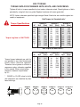
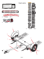
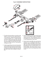
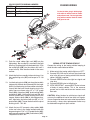
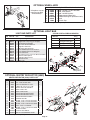
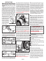
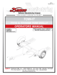
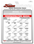
8/14 RD20019 Rev. 4 Page 1 WARRANTY POLICY & REGISTRATION Go online to www.demco-products.com to review Demco warranty policies and register your Demco product. TABLE OF CONTENTS Safety Guidelines & Instructions.................................................................................................... 2-9 Loading Angle Clearance Guide........................................................................................................9 Bot Torque.......................................................................................................................................10 Decal Location.................................................................................................................................11 Assembly Instructions................................................................................................................ 12-13 Wiring Instructions..................................................................................................................... 14-15 Parts Breakdown....................................................................................................................... 16-17 DA91 Actuator Parts Breakdown.....................................................................................................18 10” Disc Brake Parts Breakdown and List.......................................................................................19 Fender Assembly.............................................................................................................................20 Tow Dolly Options...................................................................................................................... 21-22 Operating Instructions.....................................................................................................................23 ! warning: To Prevent Serious Injury Or Death • Exceeding weight limitations or not using a towing vehicle larger and at least 1,000 lbs. heavier than the tow dolly and the towed vehicle combined can result in loss of towing vehicle control, separation of the tow dolly from the towing vehicle, or separation of the towed vehicle from the tow dolly • All vehicles to be towed on Demco Tow Dollies must be towed with the front axle on the dolly. It is recommended that two people set-up and load this piece of equipment If you are planning to tow a new or late model full size car, we recommend the 8-1/2’ wide unit. “Reporting Safety Defects” If you believe that your vehicle has a defect which could cause a crash or could cause injury or death, you should immediately inform the National Highway Traffic Safety Administration (NHTSA) in addition to notifying DEMCO. If NHTSA receives similar complaints, it may open an investigation, and if it finds that a safety defect exists in a group of vehicles, it may order a recall and remedy campaign. However, NHTSA cannot become involved in individual problems between you, your dealer, or DEMCO. Page 2 To contact NHTSA, you may either call the Auto Safety Hot line toll-free at 1-800-424-9393 (or 366-0129 in Washington, D.C. area) or write to: NHTSA, U.S. Department of Transportation Washington, D.C. 20590. You can also obtain other information about motor vehicle safety from the Hot line. SAFETY TAKE NOTE! THIS SAFETY ALERT SYMBOL FOUND THROUGHOUT THIS MANUAL IS USED TO CALL YOUR ATTENTION TO INSTRUCTIONS INVOLVING YOUR PERSONAL SAFETY AND THE SAFETY OF OTHERS. FAILURE TO FOLLOW THESE INSTRUCTIONS CAN RESULT IN INJURY OR DEATH. THIS SYMBOL MEANS -ATTENTION -BECOME ALERT -YOUR SAFETY IS INVOLVED! SIGNAL WORDS Note the use of the following signal words DANGER, WARNING, and CAUTION with the safety messages. The appropriate signal word for each has been selected using the following guidelines: DANGER: Indicates an imminently hazardous situation that, if not avoided, will result in death or serious injury. This signal word is to be limited to the most extreme situations typically for machine components which, for functional purposes, cannot be guarded. warning: Indicates a potentially hazardous situation that, if not avoided, could result in death or serious injury, and includes hazards that are exposed when guards are removed. It may also be used to alert against unsafe practices. caution: Indicates a potentially hazardous situation that, if not avoided, may result in minor or moderate injury. It may also be used to alert against unsafe practices. If you have questions not answered in this manual, require additional copies, or if your manual is damaged, please contact your dealer or Demco, 4010 320th Street, P.O. Box 189, Boyden, IA 51234 ph: (712) 725-2311 Toll Free: 1-800-543-3626 Fax: (712) 725-2380 http://www.demco-products.com Page 3 SAFETY...you can live with it Equipment safety guidelines Every year many accidents occur which could have been avoided by a few seconds of thought and a more careful approach to handling equipment. You the operator, can avoid many accidents by observing and following precautions in this section. To avoid personal injury, study the following precautions and insist those working with you, or you yourself, follow them. In order to provide a better view, certain illustrations in this manual may show an assembly with a safety shield removed. However, equipment should never be operated in this condition. Keep all shields in place. If shield removal becomes necessary for repairs, replace shield prior to use. Replace any caution, warning, danger or instruction safety decal that is not readable or is missing. Location of such decals is indicated in this booklet. Do not attempt to operate this equipment under the influence of alcohol or drugs. Review safety instructions with all users. Operator should be a responsible adult. Do not allow persons to operate or assemble this unit until they have developed a thorough understanding of safety precautions and how it works. Do not paint over, remove, or deface any safety signs or warning decals on your equipment. Observe all safety signs and practice instructions on them. Never exceed limits of a piece of machinery. If its ability to do a job, or to do so safely is in question-don’t try it. Lighting and marking It is the responsibility of the customer to know the lighting and marking requirements of the local highway authorities and to install and maintain the equipment to ,provide compliance with the regulations. Add extra lights when transporting at night or during periods of limited visibility. Lighting kits are available from your dealer or from the manufacturer. Remember Your best assurance against accidents is a careful and responsible operator. If there is any portion of this manual or function you do not understand, contact your local authorized dealer or the manufacturer. Safety sign care • Keep safety signs clean and legible at all times. • Replace safety signs that are missing or have become illegible. • Replace parts that displayed a safety sign should also display the current sign. • Safety signs are available from your distributor, dealer parts department, or the factory. How to install safety signs: • Be sure that the installation area is clean and dry. • Decide on the exact position before you remove the backing paper. • Remove the smallest portion of the split backing paper. Page 4 • Align the decal over the specified area and carefully press the small portion with the exposed sticky backing in place. • Slowly peel back the remaining paper and carefully smooth the remaining portion of the decal into place. • Small air pockets can be pierced with a pin and smoothed out using the piece of decal backing paper. Tire safety • Failure to follow proper procedures when mounting a tire on a rim can produce an explosion which may result in a serious injury or death. • Do not attempt to mount a tire unless you have the proper equipment and experience to do the job. • Inflating or servicing tires can be dangerous. Whenever possible, trained personnel should be called to service and/ or mount tires. • Always order and install tires and wheels with appropriate capacity to meet or exceed the anticipated weight to be placed on the equipment. Before operation: • Carefully study and understand this manual. • Do not wear loose-fitting clothing which may catch in moving parts. • Always wear protective clothing and substantial shoes. • Keep wheel and lug nuts tightened to specified torque. • Assure tires are inflated evenly. • Give the unit a visual inspection for any loose bolts, worn parts, or cracked welds, and make necessary repairs. Follow the maintenance safety instructions included in this manual. • Be sure there are no tools lying on or in the equipment • Do not use the unit until you are sure that the area is clear, especially around children and animals. • Don’t hurry the learning process or take the unit for granted. Ease into it and become familiar with your new equipment. • Practice operation of your equipment and its attachments. Completely familiarize yourself and other operators with it’s operation before using. • Make sure that the brakes are evenly adjusted (if equipped with brakes) • Securely attach to towing unit. Use a high strength, appropriately sized hitch pin with a mechanical retainer and attach a safety chain. • Do not allow anyone to stand between the tongue or hitch and the towing vehicle when backing up to the equipment. • Make Sure the tow rating on vehicle is high enough for what it is towing. Page 5 During operation • SAFETY CHAIN -A safety chain must be obtained and installed. Always follow state and local regulations regarding safety chain and auxiliary lighting when towing equipment on a public high way. Be sure to check with local law enforcement agencies for your own particular regulations. Only a safety chain (not an elastic or nylon/plastic tow strap) should be used to retain the connection between the towing and towed machines in the event of separation of the primary attaching system. • Install the safety chains by criss crossing chains under tongue and secure to draw bar cage, mounting loops, or bumper frame. • Beware of bystanders, PARTICULARLY CHILDREN! Always look around to make sure that it is safe to start the engine of the towing vehicle or move the unit. This is particularly important with higher noise levels, as you may not hear people shouting. • NO PASSENGERS ALLOWED- Do not carry passengers anywhere on or in equipment. • Do not clean, lubricate, or adjust your equipment while it is moving. • When halting operation, even periodically, set the or towing vehicle brakes, shut off the engine, and remove the ignition key. • Be extra careful when working on inclines. • Maneuver towing vehicle at safe speeds. • Avoid loose fill, rocks, and holes; they can be dangerous for equipment operation or movement. • Allow for unit length when making turns. • Keep all bystanders and pets clear of the work area. • Operate the towing vehicle from the operators seat only. • Never stand alongside of unit with engine running or attempt to start engine and/or operate machine while standing alongside of unit. • Never leave running equipment attachments unattended. • As a precaution, always recheck the hardware on equipment following every 100 hours of operation. Correct all problems. Follow the maintenance safety procedures. Following operation • Following operation, or when unhitching, stop the towing vehicle, set the brakes, shut off the engine and remove the ignition keys. • Store the unit in an area away from human activity. • Do not permit children to play on or around the stored unit. • Make sure all parked machines are on a hard, level surface and engage all safety devices. • Wheel chocks may be needed to prevent unit from rolling. Highway and transport operations • Adopt safe driving practices: - Always drive at a safe speed relative to local conditions and ensure that your speed is low enough for an emergency stop. - Reduce speed prior to turns to avoid the risk of overturning. - Always keep the towing vehicle in gear to provide engine braking when going downhill. Do not coast. - Do not drink and drive! Page 6 • Comply with state and local laws governing highway safety on public roads. • Use approved accessory lighting flags and necessary warning devices to protect operators of other vehicles on the highway during transport. Various safety lights and devices are available from your dealer. • Local laws should be checked for all highway lighting and marking requirements. • Plan your route to avoid heavy traffic. • Be a safe and courteous driver. Always yield to oncoming traffic in all situations, including narrow bridges, intersections, etc. • Be observant of bridge loading ratings. Do not cross bridges rated lower than the gross weight at which you are operating. • Watch for obstructions overhead and to the side while transporting. • Always operate equipment in a position to provide maximum visibility at all times. Make allowances for increased length and weight of the equipment when making turns, stopping the unit, etc. Performing maintenance • Good maintenance is your responsibility. Poor maintenance is an invitation to trouble. • Make sure there is plenty of ventilation. Never operate the engine of the towing vehicle in a closed building. The exhaust fumes may cause asphyxiation. • Before working on this machine, stop the towing vehicle, set the brakes, shut off the engine and remove the ignition keys. • Be certain all moving parts and attachments have come to a complete stop before attempting to perform maintenance. • Always use a safety support and block wheels. Never use a jack to support unit. • Always use the proper tools or equipment for the job at hand. • Use extreme caution when making adjustments. • Follow the torque chart in this manual when tightening bolts and nuts. • Openings in the skin and minor cuts are susceptible to infection from brake fluid. Without immediate medical treatment, serious infection and reactions can occur. • Replace all shields and guards after servicing and before moving. • After servicing, be sure all tools, parts and service equipment are removed. • Do not allow grease or oil to build up on the actuator, any step, or platform. • When replacing bolts, refer to the owner’s manual. • Refer to bolt torque chart for head identification marking. • Where replacement parts are necessary for periodic maintenance and servicing, genuine factory replacement parts must be used to restore your equipment to original specifications. The Manufacturer will not claim responsibility for use of unapproved parts and/or accessories and other damages as a result of their use. • If equipment has been altered in any way from original design, the manufacturer does not accept any liability for injury or warranty. • A fire extinguisher and first aid kit should be kept readily accessible while performing maintenance on this equipment • Periodically check all bolts and nuts to insure proper tension or torque. • Grease the center pivot pin every 1500 miles. • An occasional drop of oil may be required on the moving parts of the tie-down winch. Page 7 Precheck And loading Safety is of utmost importance at all times. There are several items that must be checked each time before using and while using the tow dolly. Make sure all bolts are properly tightened and those requiring a set torque are up to specifications: Lug Nuts - 120 ft. lbs. Check lug nut tension after the first 5 miles and periodically thereafter. The tires must be inflated to the recommended PSI (located on side of tire). The ball hitch must latch securely around the ball and the safety ball clamp must be in position to lock the hitch on the ball. RECOMMENDED BALL HEIGHT: 18” to the top of the ball. The transport safety chains must be hooked to the frame of the towing vehicle and the towed vehicle safety chain must be hooked to the towed vehicle frame directly above the area where the chain is mounted on the tow dolly. Leave some slack in the chain to allow suspension movement. Caution the user not to attempt to back-up the tow dolly as damage may be done to the tow dolly and/or the vehicle being towed. Check to make sure that all lights are in proper working order. Examine the ramps, winches and straps, making sure they are in good condition. Be certain the safety lock pin is locking the strap winch. Re-tighten straps after the first 5 miles and every 50 miles thereafter to ensure that they are tight. The strap on the optional winch must be in good condition and should be wound neatly on winch when not in use. NOTE: The winch strap must not be left connected to the towed vehicle after it is loaded and strapped down. IMPORTANT LOADING INSTRUCTION Check your wheel tie-down straps. Your tow dolly is equipped with custom made wheel tie-down straps of a standard size that will fit most tires, however if your tires are too large or too small you will want to exchange these new straps for the proper size straps. 1. Tire too large - This is very obvious. The strap will not basket over the tire properly. Call us. We will provide at NO Charge, on an exchange basis, the proper size strap. You must return your new, unused straps and provide us with the Make and Model of your car and the tire size. 2. Tire too small - This is not as obvious. The basket will fit down over the tire very well. The problems cannot be readily seen. You must tighten the straps down solid and then check on the inside of the tire and be sure the strap, when tightened, does not come in contact with any metal that may cause wear or cutting such as strut mounts. If there is contact, you need a smaller strap. Call us. We will provide on a NO Charge, exchange basis, the proper size strap. You must return your new, unused straps and provide us with the Make and Model of your car and tire size. warning: To Prevent Serious Injury Or Death Failure to follow these instructions can result in loss of towing vehicle control, separation of the tow dolly from the towing vehicle, separation of the towed vehicle from the tow dolly reminder: Check lighting for proper operation before heading down the road. 1. Check that the WHITE ground wire of the wiring harness is connected to the tow dolly frame and the WHITE (ground) wire is connected to the frame of the towing vehicle. 2. With headlights in “ON” position, the taillight should be lighted. 3. Start engine and have someone depress brake pedal. Brake lights of the tow dolly and towing vehicle should come “on” and “off” simultaneously with each application. 4. Put left turn signal on. Left turn light of tow dolly and towing vehicle should flash simultaneously. Should the turn signal light of the tow dolly function opposite to those of the towing vehicle, it is probable that the YELLOW and GREEN wires have been reversed. Check the plug connection under the tongue of the tow dolly to make sure wire colors are not crossed at that point. If plug connection is correct, correct problem by reversing yellow and green wire connection on the towing vehicle. Page 8 The owner assumes all responsibility for the towing vehicle’s fitness and suitability to perform the towing task in a safe, legal, and reliable manner. These responsibilities include, but are not limited to: Compliance with towing restrictions as stated by the towing vehicle's owners manual and/or manufacturer. Towing vehicle must have as a minimum a Class 3-5,000 lb.(for non-brake units) or a Class 4-6,000 lb.(for brake units) hitch and hitch ball. Do not use any other size hitch ball. Towing vehicle must be in good condition. Towing vehicle must have a current federal and/or state inspection where applicable, and comply with any applicable laws. The towing vehicle’s weight must be substantially greater (at least 1000 lbs.) than the weight of the tow dolly and towed vehicle combined. Make sure all lights are properly hooked up and operating at all times. Towing vehicle’s hitch must be approximately 18 inches off the ground (measured to the top of the ball). Make sure that the hitch and hitch ball are in good condition and not rusted, loose or stripped. Both the hitch and the hitch ball must be securely attached to the towing vehicle. Reading and following these instructions. Warning TOWED VEHICLE WEIGHT & SIZE LIMITATIONS: Tread Width Body Width TI210 TI210SB . Check your vehicle owners manual or registration for vehicle weight. Towing vehicle must be larger and at least 1000 lbs. heavier than the towed vehicle and tow dolly combined. 42” Min. 68” Max. 68” Max. FWD RWD 3400 lbs. 3700 lbs. 4800 lbs. 5300 lbs. FWD = Front Wheel Drive Towed Vehicle RWD = Rear Wheel Drive Towed Vehicle Warning Do not load the towed vehicle with cargo. Towed vehicles exceeding weight limits will overload the tow dolly and may cause serious injury and damage to both the towed vehicle and dolly. Do not load a towed vehicle exceeding the width limit - it will obstruct the platform’s swivel action when underway and could damage the towed vehicle and/ or the tow dolly. Do not exceed 55 miles per hour or any lower posted speed limit. Loading Angle Clearance Guide Tow It Loading Angle = 16° NOTE: User’s responsibility for checking clearance IMPORTANT: Using this guideline will reduce the chance of the towed vehicles air dam, or bottom of facia from interfering with tow dolly platform and/or tire stop. “X” must be less than 3.5 x “Y”. Example: If Y measures 6” 3-1/2 x 6 = 21 X must measure less than 21” Page 9 Examine ramps, winches and straps to make sure they are in good condition. Check wheel nuts every trip. To check the towing system after hook-up, tow about 100 feet. Then stop and perform a safety check. Check the bolts, chains, tire straps, ramps, coupler latch and other items, to ensure that they are tight. In addition, check all taillights and stoplights to make sure that they are operating properly. Repeat the safety check after the first 5 miles and every 50 miles thereafter. Tire inflation must be maintained per recommendation of tire manufacturer (located on side wall of tire). Tire pressure may increase during travel - do not bleed off this increase in pressure. Recheck coupler to be sure it is properly secured to the ball. Check tightness of DD164 coupler latch. rev. 3-94 BOLT TORQUE TORQUE DATA FOR STANDARD NUTS, BOLTS, AND CAPSCREWS. Tighten all bolts to torques specified in chart unless otherwise noted. Check tightness of bolts periodically, using bolt chart as guide. Replace hardware with same grade bolt. NOTE: Unless otherwise specified, high-strength Grade 5 hex bolts are used throughout assembly of equipment. Bolt Torque for Standard bolts * GRADE 2GRADE 5GRADE 8 Torque Specifications “A” lb-ft (N.m) lb-ft (N.m) lb-ft (N.m) Torque Lug Nuts to 120 FT/LBS 1/4” 6 (8) 5/16” 10 (13) 3/8” 20 (27) 7/16” 30 (40) 1/2” 45 (60) 9/16” 70 (95) 5/8” 95 (130) 3/4” 165 (225) 7/8” 170 (230) 1” 225 (300) 9 18 30 50 75 115 150 290 420 630 (12) (25) (40) (70) (100) (155) (200) (390) (570) (850) 12 (16) 25 (35) 45 (60) 80 (110) 115 (155) 165 (220) 225 (300) 400 (540) 650 (880) 970 (1310) Bolt Torque for Metric bolts * CLASS 8.8CLASS 9.8CLASS 10.9 “A” lb-ft (N.m) lb-ft (N.m) lb-ft (N.m) 6 9 (13) 10 (14) 13 (17) Torque figures indicated are valid for non-greased or non-oiled threads and heads unless otherwise specified. Therefore, do not grease or oil bolts or capscrews unless otherwise specified in this manual. When using locking elements, increase torque values by 5%. 7 8 10 12 14 16 18 20 22 24 15 23 45 78 125 194 268 378 516 654 * GRADE or CLASS value for bolts and capscrews are identified by their head markings. GRADE-2 (21) (31) (61) (106) (169) (263) (363) (513) (699) (886) 18 25 50 88 140 216 -- -- -- -- (24) (34) (68) (118) (189) (293) -- -- -- -- 21 31 61 106 170 263 364 515 702 890 (29) (42) (83) (144) (230) (357) (493) (689) (952) (1206) Torque 11MM caliper bolts to 40 ft/lbs GRADE-5 GRADE-8 A Page 10 CLASS 8.8 CLASS 9.8 CLASS 10.9 8.8 9.8 10.9 Decal Location E WINCH OPERATING INSTRUCTIONS Remove winch lock pins (A) from strap winches on front of tow dolly. Release winch: Grasp handle (B) squeeze trigger (C) push down and pull all excess strap from winch. Lay tire strap to outside of tow dolly. Tighten straps: Place tire straps over tires centering straps and winches to tires. While tightening straps, pull cross straps forward to ensure even tightening. Tighten straps until each tire starts to flatten against tire stop. After strap is tight, insert lock pin into winch. REV 1 A. B C A DD21016 DD21016QTY. 2 Ordered 08-08-07 Ordered 03-04-08 Ordered 03-10-08 A PDF was sent to Penske 02-11-10 ordered 05-24-10 M. PDF sent to Dealer 01-07-11 03-30-11 ordered 01-30-12 ordered 04-02-12 ordered 2/25/14 PO 81346 ����������������������������������������������������������� ������� ���������������������������������������� ��������� B. DA21001QTY. 2 C. RD21008QTY. 2 E. DD21021QTY. 4 C D. RD21007QTY. 1 B D E E A A B E E C Page 11 Tow-It 2 ASSEMBLY INSTRUCTIONS 29 30 32 27 31 1 28 2 8 3 9 26 65 4 22 19 7 27 26 20 28 25 24 23 11 17 21 33 12 13 10 12 14 1. Place the mainframe on blocks or some other sturdy support so that the frame rests approximately 8”10” off the ground. Attach the tilt bed ramps (#1) as shown using three 7/16” x 1” grade 8 bolts (#2) and lock nuts (#3) on the top of each ramp and four 1/2” x 1-1/4” grade 5 bolts (#4), flatwasher (#5) and locknuts (#6) (two on each side of the ramp). Torque the 7/16” bolts to 80 ft. lbs. and torque the 1/2” bolts to 75 ft. lbs. 2. Hold the tongue (#7) up to the front of the tow dolly and locate the three bullet connectors extending out the back of the tongue and plug into the connector protruding from under the mainframe channel. Do not cross colors when making this connection. 18 16 15 Latch Handle Installation 3. Mount the tongue to the front of the tow dolly using one 5/8” x 4-1/2” grade 5 bolt (#8) and locknut(#9) (torque to 50 ft. lbs.). Do not torque over 50 ft. lbs. or the bed will not tilt. Make sure the tongue latch is in the latched position to the tilt bed. 4. Mount the latch handle (#10) to the mounting plate using the 1/2” x 1-1/4” grade 5 bolt (#11), two 1/2” flatwashers (#12), bushing (#13), and 1/2” locknut (#14) . Put stainless steel bushing (#15) into latch cable (#16) and secure to handle using 3/8” x 3/4” Epoxied grade 5 hex head bolt (#17) and 5/16” flatwasher (#18). Adjust latch so cable is snug by loosening bolt and nut and sliding handle forward or back. Page 12 5. Secure the coupler (#19) and lift handle (#20) to the front end of the tongue with two 1/2” x 4-1/2” gr.5 bolts (#21), one 1/2” x 4” gr.5 bolt (#33) and locknuts (#22) . Torque the locknuts to 60 - 70 ft. lbs. Tap the rubber grip (#23) onto the handle with a rubber hammer or a wooden mallet. 6. Remove the 7/16” x 1-1/4” bolt (#24), flatwasher, and locknut from the outer front panel of each wheel platform tire stop. Slide the tie-down winch (#25) into the channel at the front of the wheel platforms as shown. Note that #25 is the left winch. The ratchet handles are to the outside of each winch and ratchet springs are to the top. Attach two 36” towed vehicle safety chains (#26). Secure one chain to each wheel platform tire stop with the 7/16” x 1-1/4” bolt (#27), flatwasher (#28) and locknut. Torque the to 50 ft. lbs. 7. When assembling the tie-down strap to the tow dolly winch, make sure the tie-down strap does not contain any twists and the overlaps are to the inside. Weave the front of the tie-down strap through the openings in the buckle. The buckle should be approximately 8” from the end of the strap. Thread the strap end through the winch slot. Bring the strap up and thread it back through the buckle again. The buckle should be approximately 1-1/2” - 2” from the winch. 8. Bolt the fenders (#29) on using 3/8” x 1-1/2” gr. 5 bolts (#30), back-up plates (#31) and locknuts (#32) in each fender. Mount the fender with the light pocket to the rear. NOTE:It is advantageous to wire the fender lights prior to attaching the wheels. 9. Fish the three wires from main unit through the hole in fender. Page 13 10.On the left side, plug in bullet plugs with white to white, black to brown and yellow to red. On the right side, plug white to white, black to brown and green to red. 11.With a pliers, install two wire clamps on fender. From rear of fender lip, install one clamp at 5-1/2” and one at 8”. 12.Mount wheels/tires. COLOR CODE FOR WIRING HARNESS WHITE Ground BROWN Tail Lights and License Plate Light YELLOW Left Turn and Stop GREEN Right Turn and Stop Fender Wiring 36 35 41 40 39 On the left side, plug in bullet plugs with white to white, black to brown and yellow to red. On the right side, plug white to white, black to brown and green to red. 42 38 43 48 43 38 37 44 47 46 45 44 11. Push the round rubber light seal (#35) into the light pocket. Be sure the lip is secured in the light housing. Plug the pigtail into the fender light. Push the round light (#36) into the rubber seal until it snaps in firmly. Wire the other fender in the same manner. 12. Attach the tire/rim assembly to the mainframe. Use the supplied lug nuts (#37) and torque to 75 - 80 ft. lbs. 13. Lay the bracing struts (#38) out along the tow dolly tongue with the back end (the end with the larger hole in it) of the bracing strut toward the mainframe. Loosely bolt the back of each bracing strut to the trailer frame as shown using 1/2” x 1-1/2” grade 5 bolt (#39), flatwasher (#40), pivot bushing (#41) and locknut (#42). Hold up the front end (the end with the smaller hole) of each bracing strut to the tongue, slide nut plate (#48) in side tongue channels, align holes and secure with two 5/8” x 1-1/4” epoxied bolt (#43). Torque the bolts with the pivot bushing to 60 - 70 ft. lbs. 14. Attach the two 24” transport safety cables (#44) to the two holes in the angle located under the tongue using two 7/16” x 1-1/4” grade 8 bolts (#45), cable mounting washers (#46), and locknuts (#47). Torque bolts to 50 ft. lbs. Page 14 WIRING OF THE TOWING VEHICLE Connect the wiring to the towing vehicle keeping in mind the color code indicated below. 1. Make certain the towing vehicle lights are “OFF”. 2. Connect YELLOW wire to left turn signal and stop wire in the left rear of towing vehicle with the wire splicer (#01883) supplied. 3. Connect GREEN wire to the right turn signal and stop wire. 4. Connect BROWN wire to taillight wire. 5. VERY IMPORTANT - connect WHITE wire to frame of body of towing vehicle. This is the common ground and a clean metal-to-metal contact must be made. CAUTION: Many flashers for vehicle turn signals will not carry the additional load of tow dolly turn signals. If normal operation does not occur when connected to the tow dolly, a heavy duty replacement flasher may be obtained through auto parts outlets. TESTING CIRCUITRY 4. Put left turn signal on. Left turnlight of tow dolly and towing vehicle should flash simultaneously. Should the turn signal light of the tow dolly function opposite to those of the towing vehicle, it is probable that the YELLOW and GREEN wires have been reversed. Check the plug connection under the tongue of the tow dolly to make sure wire colors are not crossed at that point. If plug connection is correct, correct problem by reversing yellow and green wire connection on the towing vehicle. 1. Check that the WHITE ground wire of the wiring harness is connected to the tow dolly frame and the WHITE (ground) wire is connected to the frame of the towing vehicle. 2. With headlights in “ON” position, the taillight should be lighted. 3. Start engine and have someone depress brake pedal. Brake lights of the tow dolly and towing vehicle should come “on” and “off” simultaneously with each application. Surge brake assembly 3 12 NOTE: The spring return system has a small nut wedged in the spring area for pre-load installation. Do not remove nut. Nut will automatically drop out during first braking period. 1 6 11 9 1 12 4 5 6 1 17 19 16 2 10 17 16 8 7 13 18 14 14 1. Slide 1”O.D. x 5/8”I.D. bushing over end of rubber brake line 4. Attach wheels to the mainframe. Use supplied lug nuts, torque to 75 and insert end through hole in the angle bracket welded to the 80 ft. lbs. The retainer washers on the lug bolts next to the drum have front of the tow dolly main frame, secure the brake line end been installed at the factory (two per drum). with a retainer clip. Slit one side of a 5/8” grommet, slide over BRAKE LINES PARTS LIST brake line green/brown wires coming out mainframe tongue REF. channel, push grommet into the tongue channel. Fish the bent NO. PART NO.QTY. DESCRIPTION 12” metal brake line between the mainframe and top platform 1. 13047 6 Rubber Grommet Secure one end to the rubber brake hose and other end into 2. 12508 1 63” Brake Hose the top of the brake tee on back of tow dolly axle. Make sure 3. 11616 2 Grommet .625 OD x .375 ID x .125 these connections are tight. 4. SB13H66 1 13” Rubber Brake Hose 2. Slide spring return system (19) into tongue tube, secure actuator 5. SB7785 1 3/16” Brake Tee 6. SB544 2 44” Brake Line and lift handle to front end of tongue using two 1/2” x 5” gr. 5 7. 04017 1 Lift Handle bolts and locknuts. Secure rear of actuator using one 1/2” x 8. 02189 1 Hand Grip 4-1/2” gr.5 bolt, locknut, and two flatwashers as shown (three 9. SB7764 1 Brake Hose Clip 10. 04174 4 12mm Drum Retainer Washer bolts, two flatwashers, and three locknuts provided with DA91D 11. SB512 1 12” Brake Line (Metal) actuator). The white ground wire is attached under the head of 12. 00496 1 1-1/8” OD x 5/8” ID x 14 GA Washer the second bolt attaching the actuator. (It is very important 13. 01338 1 1/2” UNC x 4-1/2” Hex Head Bolt that a good ground is made). Torque the locknuts to 60 - 70 14. 01975 2 1/2” UNC x 5” Hex Head Bolt 16. 00085 2 1/2” Flat Washer ft. lbs. Tap the rubber grip onto the handle with a rubber ham 17. 02178 3 1/2” UNC Nylon Insert Lock Nut mer or a wooden mallet. 18. 12445-30 1 Spring Return System 3. Connect DA91 actuator to brake hose coming out the top of 19. 12238 1 Safety Cable 36” the tongue. Make sure all brake line connections are tight. Follow the installation procedure as outlined in the DA91 actuator instruction, beginning with step 3 (fill the master cylinder and Please order replacement parts by PART NO. and DESCRIPTION. the bleeding procedure for brakes). Page 15 REF. NO. PART NO.QTY. 1. - 3. 4. - 5. 6. 7. 8. - 9. 10. 11. 12. 13. 14. 15. 16. - 17. 18. 19. 20. 21. 22. 23. 5432 5433 03569-95 03570-95 03571-95 03577 03574-95 03668 03575-95 03576-95 03666 02243 05450 01864 05449 00059 05444 03572-95 03573-95 03578 01998 02002 02772 04055 00214 05337 10. 25. 26. 27. 28. 29. 30. 31. 32. 33. 34. 35. - 36. 37. 38. 39. 40. 41.. 42. 43. 44. 45. 46. 47. 48. 49. 50. 51. 52. - 53. 54. 55. 56. 57. 58. 59. 60. 61. 02243 01881 11590 11591 13047 12925 01338 02288 02189 02178 02771 12236 12238 00059 01898 12714-81 02587 02434 03503 02747-96 01254 00085 02579-95 04815 11780 11779 11979-81 02209 02210 04369 02917 09296 02933 13989 04323-96 00967 04168 04167 02592 5978 DESCRIPTION 1 Left Ratchet Winch Assembly (Plated) 1Right Ratchet Winch Assembly (Plated) 1 Ratchet Frame 1 Left Spool Tube 1 Right Spool Tube 1 Heavy Duty External Snap Ring 1 Ratchet Handle 1 18 Ga. Shim Washer 1 Left Ratchet Gear 1 Right Ratchet Gear 1 5/16” x 1-1/4” Roll Pin 3 Black Vinyl Hand Grip 1 Winch Pawl 2 Winch Pawl Spring SS 1 Winch Pawl Bushing SS 1 3/8” Flatwasher 1 3/8”-16 UNC x 3/4” Hex Bolt w/epoxy 1 Left Ratchet Pawl Arm 1 Right Ratchet Pawl Arm 1 5/16”-18 UNC x 1/2” Shoulder Screw 1 5/16” Flatwasher SS 1 1/4” Flatwasher SS 2 1/4”-20 UNC Nylon Locknut 1 1/4”-20 UNC x 1” Hex Hd. Bolt 1 1/4” Flatwasher 1 Lock Pin w/Cable 1 1 1 1 4 1 2 1 1 14 4 2 2 20 4 1 1 1 2 2 2 13 2 2 2 8 1 2 8 2 - 2 10 2 2 9 6 6 14 1 REF. NO. PART NO.QTY. 62. 5979 63. 04425 64. 11971-95 65. 05443 66. 02377 67. 04508 68. 11790 69. 04424 70. 00914 71. 04804 72. 07081 73. 05447 74. 05446 75. 11980-81 76. 03528 77. 02729-95 80. 11981 81. 02383 - 04194 82. 04270-81 83. 00907 84. 05570 85. 02578 86. 02584 87. 04083 88. 05449 05444 Vinyl Hand Grip 89. Black 90. 03382-95 Trunk Connector 91. 03574-95 Front Half Trailer Wiring Harness Wiring Harness 92. 03434 Rear Half Trailer 04221 93. 1/2” Grommet 94. 02802 10000# 2” eZ-Latch Coupler 95. 03381-95 1/2”-13UNC x 4-1/2” Hex Head Bolt (Gr.5) 96. 00007 Handle 97. 03379 1/2” I.D. Handle Grip 98. 03435 1/2”-13UNC Nylon Insert Locknut 99. 03499 7/16”-14UNC Nylon Insert Locknut 100. 03433 24” Safety Cable Clear Coating w/Hook 101. 00004 36” Safety Cable Blk w/Hook f/Surge Brake 102. 01855 3/8” Flatwasher 103. 12171 7/16”-14UNC x 1-1/2” Hex Head Bolt 104. 12253 Tongue 105. 01896 5/8”-11UNC Nylon Insert Locknut 5/8”-11UNC x 4-1/2” Hex Head Bolt 5/8”-11 UNC x 1-1/4” Hex Hd. Epoxied Bolt Bracing Strut 1/2-13UNC x 1-1/2” Hex Head Bolt 1/2” Flatwasher Pivot Bushing 3/8” I.D. x 1/2” O.D. Grommet Wearplate (four hole) 1/4”x 3/4” Flat Hd Self Tap Screw Undercarriage 7/16”-20UNF Hex Nut (gr.8) 7/16”-20UNF x 1-1/4” Epoxied Bolt (gr.8) Hub and Spindle (5 on 115mm BC) Replacement 12mm x 1.5 Stud Bolt 14 x 5.5 rim (5 on 115 mm BC) 12mm Lug Nut Chrome ST205/75R 14” “C” Radial Tire (8-1/2’ unit) Tilt Bed Ramp 1/2”-13UNC x 1-1/4” Hex Head Bolt 7/16”-20UNF Nylon Insert Locknut 7/16”-20UNF x 1” Hex Head Bolt (gr.8) 3/8”-16UNC Nylon Insert Locknut Left Fender Assembly with Lights Page 16 DESCRIPTION 1 4 2 2 2 2 1 2 6 2 2 2 2 1 2 2 1 2 - 2 8 1 1 1 1 1 1 1 1 1 1 1 1 1 1 1 1 1 2 1 5 Right Fender Assembly with Lights Tinnerman Fender Clamp 5/8” Nut Plate Cable Hanger - wire harness 7/16”-20UNF x 1-1/2” Epoxied Bolt (gr.8) Amber Fender Reflector Latch Pin Back-Up Plate for fender 3/8”-16UNC x 1-1/2” Hex Head Bolt Red Fender Reflector 3-way Plug Pigtail (tail light) Rubber Mounting Grommet for light Sealed Round Tail Light Upper Half Mainframe 3-point Tie-Down Strap w/J-Hooks & buckle Buckle (only) Top Cover / Lid 36” Safety Chain with hook 7/16” “S” Hook for safety chains Rear Tire Stop 3/8”-16UNC x 1” Hex Head Bolt 1/2”-13UNC x 1” Epoxied Bolt w/zerk 1/2” Special Flatwasher 3/16” x 3/4” Roll Pin 1-3/4” O.D. Bronze Bushing Spacer Bushing - Stainless Steel 3/8”-16 UNC x 3/4” Epoxied Hex Bolt Latch Handle Pivot Bushing Latch Handle 5/16”-18 UNC x 4” Eye Bolt 5/16”-18 UNC x 2-1/2 Hex Head Bolt 5/16-18 UNC Nylon Insert Locknut Latch Catch 5/16”-18 UNC Hex Nut Latch Block Roll Pin (5/16” x 2-1/4”) Latch Spring - Stainless Steel Latch Cable 5/16” Flatwasher Pin Safety Lock #10 NC x .75 Self-tapping Screw - 1 Safety Hook Spring Clip Replacement 1/2”-13UNC x 4” Hex Head Bolt 33 102 29 104 38 28 26 24 25 50 35 102 35 66 23 22 76 10 80 16 68 84 34 37 36 87 34 15 9 103 44 85 75 77 6 12 5 3 5 4 11 8 7 83 Left Winch Shown 36 1 36 83 18 17 12 14 13 19 20 21 82 36 37 73 74 81 62 63 63 65 Model TI210 TOW DOLLY PARTS BREAKDOWN 69 67 70 74 60 73 48 61 70 28 33 44 57 44 90 91 41 101 95 93 89 101 88 92 31 32 33 46 59 49 58 39 97 33 60 27 26 41 44 57 94 99 64 44 98 96 56 86 40 43 100 42 71 69 47 45 72 10 52 43 44 45 33 53 51 42 54 30 105 55 Page 17 MODEL DA91 ACTUATOR PARTS BREAKDOWN 13 8 17 8 14 23 **16 **1215 5482 Master Cylinder Repair Kit (gasket included) **10 ' '( /8 & 7,1 25 30 12 26 5876 eZ-Latch Coupler Repair Kit 2 7 6 22 21 4 5 2 9 24 28 19 19 27 1 3 Model 91 ACTUATOR PARTS LIST 2” eZ-Latch Coupler RATED AT 10000# Bleeding the System The first requirement for safe, sure hydraulic braking is the use of quality brake fluid. Use only DOT-3 or DOT-4 brake fluid from a sealed container. If pressure bleeding equipment is available, follow the manufacturer’s instruction in bleeding the system. If system must be bled manually, proceed as follows: Fill master cylinder with fluid. Install bleeder hose on top bleeder of first caliper to be bled. NOTE: always bleed brakes by using the top bleed screw on the caliper. Have loose end of hose submerged in brake fluid in glass container to observe bubbling. By loosening the top bleeder screw located on the caliper one turn, the system is open to the atmosphere through the passage drilled in the screw. Pump actuator with long steady strokes. The bleeding operation is completed when bubbles no longer rise to the surface of the fluid. Be sure to close bleeder screw securely. Repeat bleeding operation at each caliper. During the bleeding process, replenish the brake fluid, so the level does not fall below the 1/2 full level in the master cylinder reservoir. After bleeding is complete, make sure master cylinder reservoir is filled and filler cap is securely in place. After the bleeding operation has been completed, apply pressure to the system and check the whole brake system for leaks. REF. NO. PART NO.QTY. DESCRIPTION 1. 12925 1 10000# 2” eZ-Latch Coupler 2. 01896 3 1/2”-13UNC x 4” Hex Head Bolt (gr.5) 3. 02178 3 1/2”-13UNC Nylon Insert Lock Nut 4. 05426 1 Front Shock Pin (drop tube actuators) 5. 11079-95 1 Drop Tube Actuator Slider (plated) 6. SB12426 1 Damper/ Shock 7. 11164-95 1 3 Bolt Mount Outer Case (plated) 8. 05424 2 5/16” External Tooth Lock Washer 9. 12557 1 Rue Cotter Pin for 5/8” Pin **10. 05408 1 3/32” Cable with hooks **12. 05693-95 1 Emergency Lever Spring (plated) 13. 05961 2 5/16”-18UNC x 5/8” Hex Head Bolt (gr.5) 14. 00618 4 1/4-20UNC x 2” Hex Head Bolt (gr.5) 15. 00057 4 1/4” Lock Washer **16. 05951 1 Emergency Lever Assembly 17. 03876 1 Master Cylinder Cap w/ Diaphragm & O-ring - 05849 1 O-Ring Only (not shown) 18. 05977 1 Push Rod Assembly 19. 00062 4 1/4”-20 UNC Hex Nut ** 20. 09153 - Plastic Master Cyl. Gasket ONLY 21. 11190 1 Master Cylinder 22. 14798 1 90° Fitting ** 23. 03866-95 1 Lever Guide (plated) 24. 05687 1 Master Cylinder Protective Boot 25. 05986-95 1 Connecting Pin (plated) 26. 10965 1 Upper Slider 27. 10966 1 Lower Slider 28. 10967 2 Side Spacers 29. 12557 1 Master Cylinder Cap 30. 12397 1 Rue Cotter Pin for 7/8” Pin Page 18 - - - - 8669113 5401 5482 5876 - DA91 Actuator w/ 2” eZ-Latch Coupler - Lever Replacement Kit (incl. items w/**) - Master Cyl. Replacement Kit (disc) - eZ-Latch Coupler Repair Kit Please order replacement parts by PART NO. and DESCRIPTION DISC BRAKE PARTS BREAKDOWN AND PARTS LIST 1 7 10 9 5 2 4 6 olt B oxy 3 Ep 8 PARTS LIST REF. NO. ASSEMBLY 1. Begin by mounting the Hub Assembly and the Caliper Mounting Bracket (#1) to the Forged Arm using the (#6) 7/16” Epoxied Bolts (as shown). 2. Now place the Rotor (#2) onto the Hub Assembly as shown in the diagram. 3. Make sure the Brake Pads (#4) are correctly placed in the Caliper (#3). 4. Place Caliper (#3) over the Rotor (#2), and secure it to the Mounting Bracket (#1) using the Caliper Mounting Bolts (not shown). 5. When mounting left caliper only, rotate elbow fitting 1/4 turn tighter (clockwise) to position elbow fitting correctly. Hook up Brake Hoses (#5) and replace the Rim and Tire. PART reqd NO.QTY. DESCRIPTION 1. 13920-92 2 2. 03927-92 2 3. 13825-92 2 4. 13824 1 5. SB544 2 6. 02377 8 7. 04369 2 - 02917 - 8. 02933 10 9. 09296 2 10. 5965 2 - 14179 - - 14798 1 - - 2 - - 2 - - 2 - - 2 Caliper Mounting Plate Rotor Disc Brake Caliper Complete Brake Pads (for one complete axle) Brake Line .188 x 44” 7/16”-20UNF Gr8 x 1-1/2” Epoxy Hex Hd Bolt Hub (5 on 115mm Bolt Circle) 12mm x 1-1/2” Replacement Stud Bolt 12mm Lug Nut Chrome 14x5.5” White Rim (115mm Bolt Circle) Rim and Tire Assembly Kit Disc Brake Fitting (includes items listed below) 90° Fitting (not shown) Bleeder Valve Rubber Bushing Stainless Steel Bushing Stainless Steel Bolt Please order replacement parts by PART NO. and DESCRIPTION. Page 19 Fender Assembly 3 3 3 3 3 3 3 8 6 3 3 7 1 5 4 PARTS LIST '5,//)255,9(7+2/(6 REF. NO. PART NO.QTY. DESCRIPTION 5978 - Left Fender Assembly 5979 -Right Fender Assembly 1. 2. - 3. 4. 5. 6. 7. 8. - 04425 04508 04804 14722 05443 05446 05447 07081 14121 14122 2 1 1 9 1 1 1 1 1 1 Tinnerman U-clamp Amber Reflector (not shown) Red Reflector (not shown) 3/16” x 1/2” Pop Rivet Nylon Cable Hanger 4” Round Tail Light Rubber Grommet for Light Pigtail 3 Wire Plug In Left Fender Assembly Right Fender Assembly Please order replacement parts by PART NO. and DESCRIPTION. Page 20 OPTIONAL WINCH 5 PARTS LIST REF. NO. PART NO.QTY. DESCRIPTION 2 6 1 KK2W 04620 04621 01738 02207 02592 02769 00059 1. - 2. 3. 4. 5. 6. 4 3 1 1 - 1 1 3 2 2 Optional Winch Winch Mechanism (1400 capacity) Replacement Handle Strap Assembly (includes strap & hook) 3/8”-16UNC x 3” Hex Hd. Bolt 3/8”-16UNC Nylon Insert Locknut 3/8”-16UNC x 4” Hex Head Bolt 3/8” Flatwasher Please order replacement parts by PART NO. and DESCRIPTION. * All options may not mount on tow dolly simultaneously.* 4 OPTIONAL TOOL BOX 7 PARTS LIST 1. 2. 3. 4. 5. 6. 7. RKTB 00059 02592 02718 00182 02717 00907 02759 7 Optional Tool Box 3/8” Flatwasher 3/8”-16UNC Nylon Insert Locknut Tool Box Small Hair Pin Mounting “Z” Bracket 3/8”-16UNC x 1” Hex Head Bolt (gr.5) 3/8”-16UNC x 3” Square U-Bolt 1 4 8 1 1 2 4 2 2 6 5 Please order replacement parts by PART NO. and DESCRIPTION. * All options may not mount on tow dolly simultaneously.* OPTIONAL SPARE TIRE and MOUNT PARTS LIST 5 REF. NO. PART NO.QTY. DESCRIPTION 3 2 6 1 7 4 5965 1. 2. 04826 09296 3. 4. 5. 6. 7. RKSTM 02719 02213 02759 00059 02592 1 Optional Spare Tire 1 ST205/75R 14”x”C” BSW Radial Tire 1 5.5 x 14” Rim 1 1 2 2 2 4 Spare Tire Mounting Bracket Spare Tire Bracket Wheel Nut (12mm) 3/8”-16UNC Square U-Bolt 3/8” Flatwasher 3/8”-16UNC Nylon Insert Locknut Please order replacement parts by PART NO. & DESCRIPTION. * All options may not mount on tow dolly simultaneously.* Page 21 3 OPTIONAL WHEEL JACK 2 * All options may not mount on tow dolly simultaneously.* 7 1 1 - 11683 1 Optional Wheel Jack w/ hardware 1. 02769 4 3/8”-16 UNC x 4 Hex Head Bolt 2. 00060 4 3/8” Lock Washer 3. 00061 4 3/8”-16 UNC Hex Nut 4. 03646 1 Replacement Wheel only 5. 14542-95 1 Wheel Bushing for replacement only 6. 03129 1 Jack 7. 13303 1 Plastic Cap Please order replacement parts by PART NO. and DESCRIPTION. 5 4 OPTIONAL LIGHT BAR LIGHT BAR PARTS LIST COLOR CODE for WIRING HARNESS WiringTriple Wire Harness Plug WHITE Ground WHITE BROWN Tail Lights and BLACK License Plate Light YELLOW Left Turn and Stop RED GREEN Right Turn and Stop RED REF. NO. PART NO.QTY. DESCRIPTION 1. 2. 3. 4. 5. 6. 7. 8. 9. 10. 11. 12. 13. - KKLB 02731 02313 02308 04869 02732 02734 02772 02770 00214 01778 01883 02198 02312 01886 1 1 2 2 6 2 2 2 2 2 4 6 1 6 2 Optional Light Bar Light Bar Framework Pigtail with 3-way Plug (for tail light) Sealed Round Tail Light #8 x 3/4” Oval Head Screw Light Bar Side Plate Mounting Clip with Strap 1/4”-20UNC Nylon Insert Locknut 1/4”-20UNC Nylon Insert Wing Nut 1/4” Flatwasher 3” Suction Cup w/ 1/4” x 3/4” Oven Head Bolt Electrical Wire Splicer Light Bar Wire Harness Tinnerman Nut Wire Clip 7 3 5 1 2 3 4 7 10 5 8 9 10 6 13 6 Left Side 2 Please order replacement parts by PART NO. and DESCRIPTION. 98 12 11 10 To Tow dolly Right 10 Side Connector Trunk Connector on towing vehicle 10 Optional Sentry Deflector (5950) Sentry Deflector (5950) Parts List ITEM 1 2 3 4 5 6 PART # 02128 02592 04193 02759 05337 10131 7 8 9 10 11 12 13 14 15 16 17 18 19 10132 10133 10134 10135 10136 10183 10184 10185 10186 11264 11265 13731-81 13732-81 DESCRIPTION U-BOLT, SQ, .375NC X 2.063 X 3.00 NUT, .375NC NYLON LOCK CAP PLUG SQUARE 2 X 18 GA U-BOLT, SQ, .375 X 3.125 X 4.00 SAFETY LOCK PIN ASSEMBLY ROCK GUARD, LEFT ROCK GUARD, RIGHT DEFLECTOR CENTER SECTION DEFLECTOR MOUNTING PLATE DEFLECTOR BRACE/HANDLE RETAINER BUTTON SCREW, .25 NC X .50 PHILLIPS HEAD SCREW, .25 NC X .75 PHILLIPS HEAD SCREW, .25 NC X 1.00 PHILLIPS HEAD T-NUT, .25 NC X .41 BARREL SCREW, .25 NC X 1.50 PHILLIPS HEAD SPACER BUSHING UPRIGHT POST MOUNT SENTRY CROSSMEMBER TD MNT QTY 2 8 3 2 1 1 1 2 2 2 4 17 4 4 23 2 2 1 1 Please order replacement parts by PART NO. and DESCRIPTION. 15 8 15 6 15 15 8 5 15 15 15 12 11 2 9 15 17 15 10 2 1 11 14 12 12 7 Page 22 13 12 12 16 14 12 3 19 3 1 18 2 2 4 INSTRUCTIONS Read these instructions completely before hooking, unhooking or using the tow dolly. Be sure all loading and unloading takes place on a level surface. 1Make sure towing vehicle’s parking brake is fully engaged. Tow dolly must be completely and properly hooked up to the truck before loading towed vehicle. Secure ball hitch to 2” (5,000 lb. rating for non-brake units; 6,000 lb. for brake units) towing vehicle ball. Make sure that the hitch and the hitch ball are in good condition and not rusted, loose or stripped. Both the hitch and the hitch ball must be securely attached to the towing vehicle. Make sure hitch is locked down and coupler hand wheel is tight. Crisscross safety chains under tongue and secure to towing vehicle. Connect tow dolly wire harness to towing vehicle and make sure lights operate correctly. If the tow dolly is equipped with surge brakes, securely fasten the brake actuator cable S-hook in a straight connection to the towing vehicle. Keep the cable connection at the towing vehicle as centered as (allow some possible slack for turning). 2To release tie down strap for loading release safety pin and unroll straps by grasping ratchet handle pawl (A) and ratchet handle (B) at the same time and push down. Unroll strap enough to remove strap hooks and lay on the ground in front of winches. (Any vehicle mounted on tow dolly must be mounted with front of the vehicle facing forward.) Drive towed vehicle onto the platform until tires touch the wheel stops on each side of the platform and platform returns to original level and locked position. Place towed vehicle in park or in gear, and fully engage parking brake. Lock steering wheel on towed vehicle with front tires in a straight position. If the towed vehicle does not have a locking steering column the steering wheel must be tied securely. Towed vehicle tires must fit in wheel troughs without overhanging sides. Bed will automatically latch as vehicle is loaded. Visually check the latch to be sure it is secured. 7Disconnecttowedvehicledriveshaft (rear wheel drive and 4-wheel drive vehicles). Simply placing transmission in neutral is not sufficient to prevent damage to transmission. You must disconnect the drive shaft at the rear axle and remove or secure it to the frame or other structural member. If the driveshaft is removed it may be necessary to cap the transmission tail shaft to prevent transmission fluid loss. Rear-engine transaxle vehicles cannot be towed with a tow dolly. (ALL VEHICLES MOUNTED ON THE TOW DOLLY MUST BE MOUNTED WITH THE FRONT OF VEHICLE FACING FORWARD). Consult your vehicle’s owners manual to help determine if and how your vehicle is suitable to be towed. 8Release towed vehicle parking brake and ensure that the steering wheel is locked in a straight forward position. If the vehicle is not equipped with locking steering column, the steering wheel must be tied securely in a straight forward position. Drive approximately 100 feet. Stop and perform a safety check. Check tire straps, bolts, chains, coupler, tilt bed and other items to ensure that they are tight and in the correct position. In addition, check all taillights and stoplights to make sure that they are operating properly. Repeat the safety check after the first 5 miles and every 50 miles thereafter. 5Center tie-down winches in front of tires on towed vehicle and place straps over tires. Place one tie-down strap over each front tire on towed vehicle and secure. If your tow dolly has straps with rear hooks, place one tie-down strap over each tire and secure to rods located at the rear of each platform. NOTE: The short side of the hook must face the rear of the tow dolly. Make sure tie-down winch is centered with the tire before tightening straps. Tighten each strap securely with ratchet winch. While tightening straps, pull cross strap forward to ensure even tightening. Tighten straps until each tire starts to flatten against tire stop. After each strap is tight insert a safety pin in each winch. The winch handle should always be down (horizontal) with the safety pins in place. Retighten straps after first 5 miles and check them every 50 miles thereafter to ensure that they are tight. 3Before loading (and unloading) towed vehicle make sure platform and towed vehicle are in straight alignment. Tow dolly must be completely and properly hooked up to the towing vehicle. Towing vehicle must be at least 1000 lbs. heavier than the tow dolly and towed vehicle combined. Grasp bed release handle on tongue and pull toward coupler. This releases the tilt bed. 6Hook the towed vehicle safety chains to frame of vehicle directly above the area where the chains are mounted on the tow dolly. Leave just enough slack in the chains to allow suspension movement on the towed vehicle. Caution: Chains must not attach or go over 4Make certain vehicle is centered on the steering or brake parts of towed vehicle. ramps.With someone safely guiding you, slowly drive vehicle onto platform FRONT FORWARD. Page 23 DO NOT BACK UP!! The tow dolly is not a trailer and cannot be backed up because it swivels both at the coupler and car platform. If you must back up, unload car first, disconnect the coupler, and move car and dolly separately. Play It Safe: Park where you can pull out going forward. 9 To unload vehicle Do not unhook tow dolly from the towing vehicle until the towed vehicle is completely unloaded from tow dolly. Fully engage towing vehicle’s parking brake. Make sure that platform and towed vehicle are straight. Reinstall driveshaft, if necessary. Ensure that towed vehicle parking brake is fully engaged, then loosen and remove wheel straps. Remove vehicle safety chains from towed vehicle. Release tilt bed lock down. Release parking brake on towed vehicle and slowly back the towed vehicle off the tow dolly. 10 To pull the tow dolly empty Make sure the straps are secured in the storage position. Towed vehicle safety chains must be stored to prevent being drug on the road. Tow dollies with hook type straps, the hook attaches to the rear of the ramp for storage, then tighten strap using ratchet. The ratchet handle should always be left in a down (horizontal) position when towing tow dolly loaded or unloaded. DO NOT ATTEMPT TO PULL TOW DOLLY WITH WHEEL PLATFORM IN LOADING (tilted) POSITION. P.O. BOX 189 4010 320th St., BOYDEN, IA. 51234 PH: (712) 725-2311 FAX: (712) 725-2380 TOLL FREE: 1-800-54DEMCO (1-800-543-3626) www.demco-products.com Go online to www.demco-products.com for Demco warranty policies & product registration. Page 24