1
XG-C40XU/XE
SERVICE MANUAL
SERVICE-ANLEITUNG
S01B4XG-C40XU
LCD PROJECTOR
LCD PROJEKTOR
MODELS
MODELLE
XG-C40XU/XE
In the interests of user-safety (Required by safety regulations in some countries) the set should be restored
to its original condition and only parts identical to those specified should be used.
Im lnteresse der Benutzersicherheit (erforderliche Sicherheitsregeln in einigen Ländern) muß das Gerät in seinen
Originalzustand gebracht werden. Außerdem dürfen für die spezifizierten Bauteile nur identische Teile verwendet
werden.
CONTENTS
INHALT
Page
SPECIFICATIONS ...................................................... 2
INPORTANT SERVICE SAFTY NOTES(for USA) ...... 3
OPERATION MANUAL ............................................... 7
REMOVING OF MAJOR PARTS .............................. 13
RESETTING THE TOTAL LAMP TIMER .................. 18
THE OPTICAL UNIT OUTLINE ................................ 19
CONVERGENCE AND FOCUS ADJUSTMENT ........ 20
ELECTRICAL ADJUSTMENT ................................... 25
ADJUSTING THE PC BOARD ................................. 31
TROUBLE SHOOTING TABLE ................................ 32
CHASSIS LAYOUT ................................................... 92
BLOCK DIAGRAM .................................................... 94
OVERALL WIRING DIAGRAM .................................. 96
DESCRIPTION OF SCHEMATIC DIAGRAM ............. 98
WAVEFORMS ........................................................... 99
SCHEMATIC DIAGRAM ......................................... 100
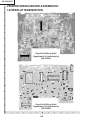
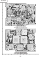
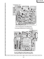
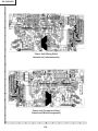
PRINTED WIRING BOARD ASSEMBLIES ............ 148
PARTS LIST
Ë ELECTRICAL PARTS ........................................ 158
Ë CABINET AND MECHANICAL PARTS .............. 178
Ë ACCESSORIES PARTS .................................... 184
Ë PACKING PARTS ............................................... 184
» PACKING OF THE SET .......................................... 185
»
»
»
»
»
»
»
»
»
»
»
»
»
»
»
»
»
»
»
»
»
»
»
»
»
»
»
»
»
»
»
»
»
»
»
»
»
Seite
TECHNISCHE DATEN ............................................. 48
HINWEISE FÜR DAS WARTUNGSPERSONAL ...... 49
BEDIENUNGSANLEITUNG ..................................... 50
ENTFERNEN DER HAUPTTEILE ............................ 56
NULLSTELLUNG DES LAMPENBETRIEBSSTUNDENZÄHLERS (GESAMTZEIT).... 61
ÜBERSICHT DER OPTIKEINHEIT .......................... 62
EINSTELLUNG VON KONVERGENZ UND
BRENNPUNKT ......................................................... 63
ELEKTRISCHE EINSTELLUNG ............................... 68
EINSTELLUNG DER PC-PLATINE .......................... 74
FEHLERSUCHTABELLE .......................................... 75
CHASSIS-ANORDNUNG ......................................... 92
BLOCKSCHALTBILD ................................................ 94
GESAMTSCHALTPLAN ........................................... 96
BESCHREIBUNG DES SCHEMATISCHEN
SCHALTPLANS ........................................................ 98
WELLENFORMEN ................................................... 99
SCHEMATISCHER SCHALTPLAN ........................ 100
LEITERPLATTENEINHEITEN ................................ 148
ERSATZTEILLISTE
Ë ELEKTRISCHE BAUTEILE ................................ 158
Ë GEHÄUSE UND MECHANISCHE BAUTEILE ... 178
Ë ZUBEHÖRTEILE ................................................ 184
Ë VERPACKUNGSTEILE ...................................... 184
VERPACKEN DES GERÄTS .................................. 185
SHARP CORPORATION
1
XG-C40XU/XE
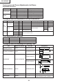
Specifications
Product type
Model
Video system
Display method
LCD panel
Lens
Projection lamp
Contrast ratio
Video input signal
S-video input signal
Horizontal resolution
Audio output
Computer RGB input signal
Pixel clock
Vertical frequency
Horizontal frequency
Computer control signal
Speaker system
Rated voltage
Input current
Rated frequency
Power consumption
Operating temperature
Storage temperature
Cabinet
I/R carrier frequency
Laser pointer of remote control
Dimensions (approx.)
Weight (approx.)
Supplied accessories
Replacement parts
LCD Projector
XG-C40XU/XE
PAL/SECAM/NTSC 3.58/NTSC 4.43/DTV 480P/DTV 720P/DTV 1080I
LCD panel × 3, RGB optical shutter method
Panel size: 22.9 mm (0.9") (13.9 [H] × 18.5 [W] mm)
Display method: Translucent TN liquid crystal panel
Drive method: TFT (Thin Film Transistor) Active Matrix panel
No. of dots: 786,432 dots (1,024 [H] × 768 [V])
1–1.3 × zoom lens, F1.7–2.0, f = 33–43 mm
DC 200 W lamp
250:1
RCA Connector: VIDEO, composite video, 1.0 Vp-p, sync negative, 75 Ω terminated
RCA Connector: AUDIO, 0.5 Vrms more than 22 kΩ (stereo)
4-pin Mini DIN connector
Y (luminance signal): 1.0 Vp-p, sync negative, 75 Ω terminated
C (chrominance signal): Burst 0.286 Vp-p, 75 Ω terminated
560 TV lines (video input), 750 TV lines (DTV 720P input, Dot by Dot)
3 W (monaural)
15-PIN MINI D-SUB CONNECTOR (INPUT 1, 2):
RGB separate/composite sync/sync on green type analog input: 0–0.7 Vp-p, positive,
75 Ω terminated
STEREO MINIJACK: AUDIO, 0.5 Vrms, more than 22 kΩ (stereo)
HORIZONTAL SYNC. SIGNAL: TTL level (positive/negative) or composite sync (Apple only)
VERTICAL SYNC. SIGNAL: Same as above
12–230 MHz
43–200 Hz
15–126 kHz
9-pin Mini DIN female connector (RS-232C Input Port)
8 cm (3 3⁄32") round
AC 100–240 V
3.3 A
50/60 Hz
300 W
41°F to + 104°F (+ 5°C to + 40°C)
-4°F to + 140°F (– 20°C to + 60°C)
Plastic
38 kHz
Wave length: 650 nm / Max. output: 1 mW / Class II Laser Product
9 1/64" (W) × 4 49/64" (H) × 12 13/64" (D) (229 × 121 × 310 mm) (main body only)
9 19/32" (W) × 5 9/32" (H) × 14 7/64" (D) (243.5 × 134 × 358.4 mm) (including adjustment feet
and projecting parts)
10.6 lbs. (4.8 kg)
Remote control, Two AA size batteries, Power cord (11' 10" 3.6m), Computer RGB cable
(9' 10" 3 m), Computer audio cable (9' 10" 3 m), USB mouse control cable (3' 3" 1 m),
DIN-D-sub RS-232C cable (6 45/64" 15 cm), Remote mouse receiver, Extra air filter, Lens cap
(attached), CD-ROM, LCD projector operation manual, LCD projector quick references,
Sharp Advanced Presentation Software operation manual
Lamp unit (Lamp/cage module) (BQC-XGC40XU/1), Remote control (RRMCG1579CESA),
(RRMCG1584CESA),AA size batteries, Power cord (QACCU5013CEZZ(XG-C40XU),
QACCB5024CENA(XG-C40XE),QACCV4002CEZZ(XG-C40XE)), Computer RGB cable
(QCNWG0002CEZZ), Computer audio cable (QCNW-4870CEZZ), USB mouse control
cable (QCNWG0007CEPZ), DIN-D-sub RS-232C cable (QCNW-5288CEZZ), Remote mouse
receiver (RUNTK0673CEZZ), Air filter (PFILD0076CEZZ), Lens cap (GCOVH1307CESB),
CD-ROM (UDSKA0053CEN1),(UDSKA0057CEN1), LCD projector operation manual
(TINS-7482CEZZ),(TINS-7533CEZZ), LCD projector quick references (TINS-7483CEZZ),
(TINS-7534CEZZ, TINS-7535CEZZ, TINS-7536CEZZ), Sharp Advanced Presentation
Software operation manual (TINS-7538CEZZ),(TINS-7537CEZZ)
This SHARP projector uses LCD (Liquid Crystal Display) panels. These This unit has some inactive TFTs within acceptable tolerances which
very sophisticated panels contain 786,432 pixels ( × RGB) TFTs (Thin may result in illuminated or inactive dots on the picture screen. This
Film Transistors). As with any high technology electronic equipment
will not affect the picture quality or the life expectancy of the unit.
such as large screen TVs, video systems and video cameras, there
are certain acceptable tolerances that the equipment must conform
to.
Specifications are subject to change without notice.
2
XG-C40XU/XE
INPORTANT SERVICE SAFETY NOTES (for USA)
Ë Service work should be performed only by qualified service technicians who are
thoroughly familiar with all safety checks and servicing guidelines as follows:
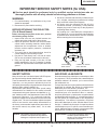
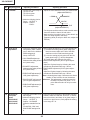
» Use an AC voltmeter with sensitivity of 5000 ohm per
volt., or higher, sensitivity to measure the AC voltage
drop across the resistor (See Diagram).
» All checks must be repeated with the AC plug
connection reversed. (If necessary, a non-polarized
adapter plug must be used only for the purpose of
completing these checks.)
Any reading of 0.3 volts RMS (this corresponds to
0.2 milliamp. AC.) or more is excessive and indicates
a potential shock hazard which must be corrected
before returning the unit to the owner.
WARNING
1. For continued safety, no modification of any circuit
should be attempted.
2. Disconnect AC power before servicing.
BEFORE RETURNING THE PROJECTOR:
(Fire & Shock Hazard)
Before returning the projector to the user, perform
the following safety checks:
1. Inspect lead wires are not pinched between the
chassis and other metal parts of the projector.
2. Inspect all protective devices such as non-metallic
control knobs, insulating materials, cabinet backs,
adjustment and compartment covers or shields,
isolation resistor-capacity networks, mechanical
insulators, etc.
3. To be sure that no shock hazard exists, check for
current leakage in the following manner:
» Plug the AC cord directly into a 120-volt AC outlet,
(Do not use an isolation transformer for this test).
» Using two clip leads, connect a 1.5k ohm, 10 watt
resistor paralleled by a 0.15µF capacitor in parallel
between all exposed metal cabinet parts and earth
ground.
AC
VOLTMETER
1.5k ohm (10W)
0.15µF
TEST PROBE
TO EXPOSED
METAL PARTS
CONNECT TO KNOWN
EARTH GROUND
12345678901234567890123456789012123456789012345678901234567890121234567890123456789012345678901212
12345678901234567890123456789012123456789012345678901234567890121234567890123456789012345678901212
12345678901234567890123456789012123456789012345678901234567890121234567890123456789012345678901212
SAFETY NOTICE
AVIS POUR LA SECURITE
Many electrical and mechanical parts in DLP Projector
have special safety-related characteristics.
These characteristics are often not evident from visual
inspection, nor can protection afforded by them be
necessarily increased by using replacement components
rated for higher voltage, wattage, etc.
Replacement parts which have these special safety
characteristics are identified in this manual; electrical
components having such features are identified by “å”
and shaded areas in the Replacement Parts Lists and
Schematic Diagrams. For continued protection,
replacement parts must be identical to those used in the
original circuit. The use of a substitute replacement parts
which do not have the same safety characteristics as
the factory recommended replacement parts shown in
this service manual, may create shock, fire or other
hazards.
De nombreuses pièces, électriques et mécaniques, dans
les projecteur à DLP présentent des caractéristiques
spéciales relatives à la sécurité, qui ne sont souvent
pas évidentes à vue.
Le degré de protection ne peut pas être nécessairement
augmentée en utilisant des pièces de remplacement
étalonnées pour haute tension, puissance, etc.
Les pièces de remplacement qui présentent ces
caractéristiques sont identifiées dans ce manuel;
les pièces électriques qui présentent ces particularités
sont identifiées par la marque “å” et hachurées dans la
liste des pièces de remplacement et les diagrammes
schématiques. Pour assurer la protection, ces pièces
doivent être identiques à celles utilisées dans le circuit
d’origine. L’utilisation de pièces qui n’ont pas les mêmes
caractéristiques que les pièces recommandées par
l’usine, indiquées dans ce manuel, peut provoquer des
électrocutions, incendies ou autres accidents.
WARNING: The bimetallic component has the primary
conductive side exposed. Be very careful in
handling this component when the power is on.
AVERTISSEMENT: La composante bimétallique dispose du
conducteur primaire dénudé. Faire
attention lors de la manipulation de cette
composante sous tension.
12345678901234567890123456789012123456789012345678901234567890121234567890123456789012345678901212
12345678901234567890123456789012123456789012345678901234567890121234567890123456789012345678901212
12345678901234567890123456789012123456789012345678901234567890121234567890123456789012345678901212
3
XG-C40XU/XE
NOTE TO SERVICE
PERSONNEL
12345678901234567890123456789012123456789012345
NOTE POUR LE PERSONNEL
D’ENTRETIEN
12345678901234567890123456789012123456789012345
12345678901234567890123456789012123456789012345
12345678901234567890123456789012123456789012345
12345678901234567890123456789012123456789012345
12345678901234567890123456789012123456789012345
UV-RADIATION PRECAUTION
12345678901234567890123456789012123456789012345
12345678901234567890123456789012123456789012345
PRECAUTION POUR LES RADIATIONS UV
12345678901234567890123456789012123456789012345
12345678901234567890123456789012123456789012345
The light source, metal halide lamp, in the LCD
projector emits small amounts of UV-Radiation.
La source de lumière, la lampe mètal halide , dans le
projecteur LCD émet de petites quantités de
radiation UV.
AVOID DIRECT EYE AND SKIN EXPOSURE.
EVITEZ TOUTE EXPOSITION DIRECTE
DES YEUX ET DE LA PEAU.
To ensure safety please adhere to the following:
Pour votre sécurité, nous vous prions de respecter
les points suivants:
1. Be sure to wear sun-glasses when servicing the
projector with the lamp
turned “on” and the top
enclosure removed.
1. Toujours porter des lunettes de soleil lors d’un
entretien du projecteur
avec la lampe allumée
et le haut du coffret retiré.
2. Do not operate the lamp outside of the lamp housing.
2. Ne pas faire fonctionner la lampe à l’extérieur du
boîtier de lampe.
3. Do not operate for more than 2 hours with the
enclosure removed.
3. Ne pas faire fonctionner plus de 2 heures avec le
coffret retiré.
UV-Radiation and Medium Pressure
Lamp Precautions
Précautions pour les radiations UV
et la lampe moyenne pression
1. Be sure to disconnect the AC plug when replacing
the lamp.
2. Allow one hour for the unit to cool down before
servicing.
3. Replace only with same type lamp. Type
CLMPF0075CE01 or BQC-XGC40XU/1 rated 85V/
200W.
4. The lamp emits small amounts of UV-Radiation, avoid
direct-eye contact.
5. The medium pressure lamp involves a risk of
explosion. Be sure to follow installation instructions
described below and handle the lamp with care.
1. Toujours débrancher la fiche AC lors du
remplacement de la lampe.
2. Laisser l’unité refroidir pendant une heure avant de
procéder à l’entretien.
3. Ne remplacer qu’avec une lampe du même type.
Type CLMPF0075CE01 or BQC-XGC40XU/1,
caractéristique 85V/200W.
4. La lampe émet de petites quantités de radiation UVéviter tout contact direct avec les yeux.
5. La lampe moyenne pression implique un risque
d’explosion. Toujours suivre les instructions
d’installation décrites ci-dessous et manipuler la
lampe avec soin.
4
XG-C40XU/XE
12345678901234567890123456789012123456789012345
12345678901234567890123456789012123456789012345
12345678901234567890123456789012123456789012345
12345678901234567890123456789012123456789012345
1234567890123456789012345678901212345678901234
UV-RADIATION PRECAUTION (Continued)
1234567890123456789012345678901212345678901234
1234567890123456789012345678901212345678901234
12345678901234567890123456789012123456789012345
PRECAUTION POUR LES RADIATIONS UV (Suite)
12345678901234567890123456789012123456789012345
12345678901234567890123456789012123456789012345
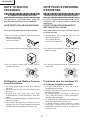
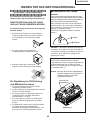
Lamp Replacement
Remplacement de la lampe
Note:
Remarque:
Since the lamp reaches a very high temperature
during units operation replacement of the lamp
should be done at least one hour after the power
has been turned off. (to allow the lamp to cool off.)
Installing the new lamp, make sure not to touch the
lamp (bulb) replace the lamp by holding its reflector
2.
[Use original replacement only.]
Comme la lampe devient très chaude pendant le
fonctionnement de l’unité, son remplacement ne doit
être effectué au moins une heure après avoir coupé
l’alimentation (pour permettre à la lampe de refroidir).
En installant la nouvelle lampe, s’assurer de ne pas
toucher la lampe (ampoule). Remplacer la lampe en
tenant son réflecteur 2.
[N’utiliser qu’un remplacement d’origine.]
1 Lamp
1 Lamp
2 Reflector
2 Reflector
DANGER ! –– Never turn the power on without the
lamp to avoid electric-shock or damage of the
devices since the stabilizer generates high voltages
at its start.
DANGER ! –– Ne jamais mettre sous tension sans
la lampe pour éviter un choc électrique ou des
dommages des appareils car le stabilisateur génère
de hautes tensions à sa mise en route.
Since small amounts of UV-Radiation are emitted
from an opening between the duct cover and the
lamp housing, it is recommended to place the LENS
CAP on the opening during servicing to avoid eye
and skin exposure (Fig. 1).
Comme de petites quantités de radiation UV sont
émises par une ouverture entre le couvercle du conduit et le botier de la lampe,il est recommandé de
placer le CAPUCHON D'OPTIQUE sur l'ouverture
pendant l'entretien pour éviter une exposition des
yeux et la peau (Fig. 1).
Note: Please obtain a lens cap before servicing a
model XG-C40XU that is received without
one.
Remarque: Priére de se procurer un capuchon
d'optique acant d'entretien un modéle
XG-C40XU qui est livré sans.
LENS CAP
LENS CAP
SH
AR
P
SH
AR
P
Figure 1.
Figure 1.
5
XG-C40XU/XE
WARNING:
High brightness light source, do not stare into the beam of light, or view directly. Be especially
careful that children do not stare directly in to the beam of light.
WARNING:
TO REDUCE THE RISK OF FIRE OR ELECTRIC SHOCK, DO NOT EXPOSE THIS UNIT TO
MOISTURE OR WET LOCATIONS.
CAUTION
The lighting flash with arrowhead within a
triangle is intended to tell the user that
parts inside the product are risk of electric
shock to persons.
RISK OF ELECTRIC SHOCK.
DO NOT REMOVE SCREWS
EXCEPT SPECIFIED USER
SERVICE SCREW
CAUTION: TO REDUCE THE RISK OF ELECTRIC SHOCK,
DO NOT REMOVE CABINET.
NO USER-SERVICEABLE PARTS EXCEPT LAMP UNIT.
REFER SERVICING TO QUALIFIED SERVICE
PERSONNEL.
The exclamation point within a triangle is
intended to tell the user that important
operating and servicing instructions are in
the manual with the projector.
CAUTION
(INLET Unit)
5A 250V
For continued protection
against a risk of fire,
replace only with same
type 5A 250V fuse.
(F761)
123456789012345678901234567890121234567890123456789012345678901212345678901234567890123456789012123
123456789012345678901234567890121234567890123456789012345678901212345678901234567890123456789012123
AVERTISSEMENT: Source lumineuse de grande intensité. Ne pas fixer le faisceau lumineux ou le regarder
directement. Veiller particulièrement à éviter que les enfants ne fixent directement le
faisceau lumineux.
AVERTISSEMENT: AFIN D’EVITER TOUT RISQUE D’INCENDIE OU D’ELECTROCUTION, NE PAS PLACER
CET APPAREIL DANS UN ENDROIT HUMIDE OU MOUILLE.
ATTENTION
L’éclair terminé d’une flèche à l’intérieur
d’un triangle indique à l’utilisateur que les
pi‘eces se trouvant dans l’appareil sont
susceptibles de provoquer une décharge
électrique.
RISQUE
D’ELECTROCUTION NE
PASRETIRER LES VIS, A
L’EXCEPTION DES VIS DE
REPARATION UTILISATEUR
SPECIFIEES
Le point d’exclamation à l’intérieur d’un
triangle indique à l’utilisateur que les
instructions de fonctionnement et
d’entretien sont détaillées dans les
documents fournis avec le projecteur.
ATTENTION: POUR EVITER TOUT RISQUE
D’ELECTROCUTION, NE PAS RETIRER LE CAPOT.
AUCUNE DES PIECES INTERIEURES N’EST REPARABLE
PAR L’UTILISATEUR, A L’EXCEPTION DE L’UNITE DE
LAMPE. POUR TOUTE REPARATION, S’ADRESSER A UN
TECHNICIEN D’ENTRETIEN QUALIFIE.
PRECAUTION
(Unite d’admission)
5A 250V
Pour une protection continue
contre les risques d’incendie,
ne remplacer qu’avec un
fusible 5A 250V du même
type.
(F761)
6
XG-C40XU/XE
OPERATION MANUAL
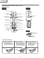
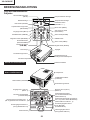
Location of Controls
Projector
MUTE button
LAMP REPLACEMENT
indicator
TEMPERATURE WARNING
indicator
POWER indicator
VOLUME buttons (+ / – )
POWER buttons (ON/OFF)
KEYSTONE button
MENU button
AUTO SYNC button
INPUT button
FREEZE button
RESIZE button
ENLARGE button
GAMMA button
BLACK SCREEN button
UNDO button
ADJUSTMENT buttons
('/"/\/|)
ENTER button
Zoom knob
Carrying handle
Remote control sensor
Kensington Security Standard
connector
Focus knob
Foot release
Front and Top View
Speaker
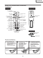
Side and RearView
Air filter/Cooling fan (Intake vent)
Cooling fan (Exhaust vent)
Remote control sensor
INPUT 1 port (HD 15)
INPUT 2 port (HD 15)
AUDIO OUTPUT terminal
(3.5mm stereo minijack)
RS-232C port (9-pin Mini DIN)
AUDIO INPUT terminal
for INPUT 1, 2
(3.5 mm stereo minijack)
OUTPUT port for INPUT 1, 2 (HD 15)
S-VIDEO INPUT 4 terminal
(4-pin Mini DIN)
AUDIO INPUT 3 terminals (RCA)
VIDEO INPUT 3 terminal
(RCA)
AC socket
7
XG-C40XU/XE
Operating the Wireless Mouse Remote Control
Remote Control
Front View
Rear View
MUTE button
POWER buttons
(ON/OFF)
VOLUME buttons
(+/–)
KEYSTONE/BLACK
SCREEN button
LEFT-CLICK
button
LASER POINTER/
MENU button
MOUSE/
ADJUSTMENT
buttons ('/"/\/|)
RIGHT-CLICK/
ENTER button
UNDO button
INPUT button
AUTO SYNC button
FREEZE button
ENLARGE button
RESIZE button
TOOLS button
GAMMA button
MOUSE/
ADJUSTMENT
switch
BACKLIGHT button
Top View
Remote control
signal transmitter
Laser
pointer
window
Inserting the batteries
in on the arrow
1 Press
mark and slide in the
direction of the arrow to
remove the battery cover.
Battery
cover
2
Insert two AA size
batteries, making sure
their polarities match the
+ and – marks inside
the battery compartment.
the side tabs of
3 Insert
the battery cover into
their slots and press the
cover in until it is
properly seated.
Battery
cover
Battery
compartment
8
XG-C40XU/XE
Using the Remote Control as a Wireless Mouse
The remote control has the following three functions:
• Projector control
• Wireless mouse
• Laser pointer
MOUSE/ADJUSTMENT switch
(Remote control)
MOUSE
ADJ.
MOUSE
Wireless mouse
Laser pointer
ADJ.
Projector control
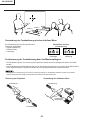
Remote Control/Mouse Receiver Positioning
• The remote control can be used to control the projector within the ranges shown below.
• The remote mouse receiver can be used with the remote control to control the mouse functions of a connected
computer within the ranges shown below.
• The signal from the remote control can be reflected off a screen for easy operation. However, the effective distance of the
signal may differ due to the screen material.
Controlling the Projector
Using the Wireless Mouse
Remote control
Remote control
7m
30˚
30˚
30˚
45˚
30˚
4m
45˚
30˚
Remote control
9
120˚
Remote
mouse
receiver
XG-C40XU/XE
Effective buttons in MOUSE mode
Use as a Wireless Mouse
Be sure the supplied remote mouse receiver is
connected to your computer.
Remote control
(Front view)
LASER POINTER
(Slide the MOUSE/ADJUSTMENT switch on
the remote control to the MOUSE position.)
MOUSE
ADJ.
BLACK SCREEN
MOUSE
RIGHT-CLICK
BACKLIGHT
• The wireless mouse may not operate correctly if your
computer serial port is not correctly set up. Refer to the
computer’s operation manual for details of setting up/
installing the mouse driver.
• For one-button mouse systems, use either the LEFT-CLICK
or RIGHT-CLICK button.
Using the remote control in a dark room
Press BACKLIGHT, and the buttons will light up. Green
lights refer to mouse operations, and red lights to
projector adjustments.
Button name
Remote control
(Rear view)
LEFT-CLICK
Position of MOUSE/ADJUSTMENT switch
ADJ.
MOUSE
LASER POINTER/MENU LASER POINTER (GREEN) MENU (RED)
BLACK SCREEN/KEYSTONE BLACK SCREEN (GREEN) KEYSTONE(RED)
RIGHT-CLICK/ENTER RIGHT-CLICK (GREEN) ENTER (RED)
MOUSE/ADJUSTMENT MOUSE (NOT LIT)
ON (NOT LIT)
LEFT-CLICK
POWER ON/OFF
ADJUSTMENT (NOT LIT)
—
VOLUME + / –
MUTE
INPUT
UNDO
FREEZE
ON (RED)
AUTO SYNC
ENLARGE
RESIZE
TOOLS
GAMMA
Use as a Laser Pointer
(Slide the MOUSE/ADJUSTMENT switch on
the remote control to the MOUSE position.)
MOUSE
ADJ.
Press LASER POINTER ( ) to activate the laser
pointer. When the button is released, the light
automatically goes off.
• For safety, the laser pointer automatically goes off after 1
minute of continuous use. To turn it on, release LASER
POINTER ( ) and press again.
10
XG-C40XU/XE
Connection Pin Assignments
Analog Computer 1 and 2 Signal Input Ports: 15-pin mini D-sub female connector
1
6
11
5
10
15
Computer Input
Analog
1. Video input (red)
2. Video input
(green/sync on green)
3. Video input (blue)
4. Reserve input 1
5. Composite sync
6. Earth (red)
7. Earth (green/sync on green)
8. Earth (blue)
9.
10.
11.
12.
13.
14.
15.
Component Input
1. PR (CR)
2. Y
3. PB
4. Not connected
5. Not connected
6. Earth (PR)
7. Earth (Y)
8. Earth (PB)
9. Not connected
10. Not connected
11. Not connected
12. Not connected
13. Not connected
14. Not connected
15. Not connected
Not connected
GND
GND
Bi-directional data
Horizontal sync signal
Vertical sync signal
Data clock
RS-232C Port: 9-pin D-sub male connector of the DIN-D-sub RS-232C cable
Pin No.
1
2
3
4
5
6
7
8
9
5
1
9
6
Signal
CD
RD
SD
ER
SG
DR
RS
CS
CI
Name
I/O
Receive Data
Send Data
Input
Output
Signal Ground
Data Set Ready
Request to Send
Clear to Send
Output
Output
Input
Reference
Not connected
Connected to internal circuit
Connected to internal circuit
Not connected
Connected to internal circuit
Not connected
Connected to internal circuit
Connected to internal circuit
Not connected
RS-232C Terminal: 9-pin Mini DIN female connector
8
7
9
3
6
5
4
2
1
Pin No.
1
2
3
4
Signal
VCC
RD
SD
EXIR
5
6
SG
ERX
7
8
9
RS
CS
ETX
Name
I/O
+ 3.3V (Reserved)
Output
Receive Data
Input
Send Data
Output
Detector of Option Unit Input
(Reserved)
Signal Ground
IR Receive Signal from Input
IR Amplifier (Reserved)
Request to Send
Output
Clear to Send
Input
IR Transmit Signal
Output
(Reserved)
11
Reference
Not connected
Connected to internal circuit
Connected to internal circuit
Not connected
Connected to internal circuit
Not connected
Connected to internal circuit
Connected to internal circuit
Not connected
XG-C40XU/XE
Rear Vie
Dimensions
25 64
23
/64 (9)
3 51/64 (96.5)
23 64
105/16 (262)
147/64 (358.4)
5 19/32 (142)
1213/64 (310)
2 13/32 (61)
/ (9)
2 13 /32 (61)
5433/64 (138.5)
9 11/32 (237.5)
49 1/64 (124.5)
1 5/16 (33.5)
/ (10)
29/32 (23)
3 53/64 (97.5)
1 5/64 (27.5)
Top View
w
/ (16)
63
1 11/16 (43) 2 /64 (76)
13
/ (25)
7 16
/ (11)
Front View
/ (13)
449/64 (121)
/32 (10.5)
17 32
113/16 (30)
3 21/32 (93)
3 17/64 (83)
9 1/64 (229)
63 64
3 17/64 (83)
58
919/32 (243.5)
5 9/32 (134)
Side View
BottomView
Units: inches (mm)
12
XG-C40XU/XE
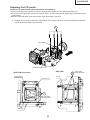
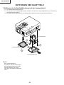
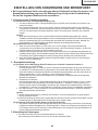
REMOVING OF MAJOR PARTS
1. Removing the Intake cover and lamp unit
S
A
H
P
R
1-1. Detach the Intake cover.
1-2. Loosen the lamp cover screw and draw out the lamp cover in the direction of arrow (toward yourself).
1-3. Remove the two lamp unit lock screws. Detach the lamp unit.
Lamp unit
1-3
1-3
1-2
Intake cover
1-1
Lamp cover
Note:
When replacing the lamp, make sure
that there is a clearance of over
8mm between the terminal and the
lamp snap-on spring (and other
metallic parts).
13
XG-C40XU/XE
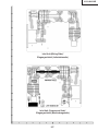
2. Removing the top and rear cabinets
2-1. Remove the four rear cabinet lock screws.
2-2. Remove the four terminal board lock screws off the rear cabinet. Unhook and detach the rear cabinet from
below.
2-3. Remove the four top cabinet lock screws from below.
H
S
R
A
P
Press both sides of the bottom
cabinet in the directions of
arrow to undo the hooks. Lift
and detach the top cabinet.
2-1
2-3
Hook
2-2
2-4. Slowly lift the top cabinet and disconnect the operation key unit connector (KY). Then take away the top
cabinet.
Top cabinet
(KY)
2-4
Rear cabinet
14
XG-C40XU/XE
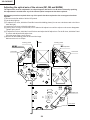
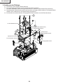
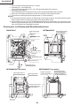
3. Removing the PWB units
3-1. Disconnect the connectors from the output unit.
3-2. Remove the four PC I/F unit lock screws.
Remove the two screws and the earth shield, and take out the PC I/F unit.
3-3. Remove the spacer (stud bolt) and the three screws off the output unit. Lift the output unit, together with the
signal unit, off the position.
3-4. Remove the S-out/REG unit angle lock screw and take out the S-out/REG unit.
3-2
PC I/F Unit
(TP)
(L)
3-3
3-3
3-1
3-3
(FN)
(Q)
(EB)
Spacer (stud bolt)
Output Unit
3-4
(FP)(FS)
(SO)
S-out/REG Unit Angle
3-2
(F)
Signal Unit
(EB)
3-1
PC Terminal Unit
(EA)
(SP)
(SO)
S-out/REG Unit
Video Unit
15
XG-C40XU/XE
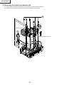
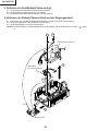
4. Removing the optical mechanism unit
4-1. Remove the six optical mechanism unit lock screws. Lift the unit off the position.
4-2. Remove the two lamp socket holder lock screws and take out the holder.
4-1
Duct Fan Unit
4-2
Optical Mechanism Unit
16
XG-C40XU/XE
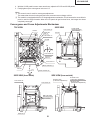
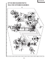
5. Removing the Power/Ballast unit assembly
5-1. Remove the Power/Ballast unit assembly lock screw.
5-2. Remove the (FG) lead lock screw.
5-3. Lift the Power/Ballast unit assembly off the position.
6. Removing the ballast unit and inlet unit
6-1. Disconnect the connector (PA) from the inlet unit. Take out the AC power switch.
6-2. Remove the Inlet unit lock screw.
6-3. Pull the inlet unit toward yourself off the position.
Note: Before installing the lamp cover, make sure the AC power switch is at the " " (OFF) position.
5-1
5-2
Power/Ballast Unit Ass'y
(FG)
(TP)
5-3
AC power switch
(for Lamp replacement)
(BA)
(PA)
6-1
(FG)
6-2
(PA)
6-3
Inlet Unit
17
XG-C40XU/XE
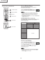
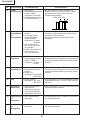
RESETTING THE TOTAL LAMP TIMER
When the lamp has been replaced, reset the total lamp timer in the following steps.
Resetting procedure
1. While holding down the “ENTER”, “ADJ."” and “ADJ.|” keys on the set at the same time, turn on the main
power switch (located side the AC inlet).
2. Now the total lamp timer is reset to zero. “000H” appears on the screen.
LAMP
POWER
ON
I
TEMP.
+
MUTE
VOLUME
OFF
MENU
KEYSTONE
AUTO
SYNC
INPUT
'
BLACK SCREEN
'
'
ENLARGE
'
FREEZE
RESIZE
GAMMA
ENTER
UNDO
B
ENTER
ADJ."
ADJ.|
Lamp
The lamp in this projector operates for approximately 2,000 cumulative hours, depending on the usage environment. It is recommended that the lamp be replaced after 1,900 cumulative hours of use or when you notice a
significant deterioration of the picture and colour quality. The lamp usage time can be checked with the On-screen
Display.
CAUTION
• Intense light hazard. Do not attempt to look into the aperture and lens while the projector is operating.
• As the usage environment can vary significantly, the projector lamp may not operate for 2,000 hours.
Condition
The LAMP REPLACEMENT
indicator lights up red, and “LAMP”
and “ ” will flash in yellow in the
lower-left corner of the picture.
Problem
• Lamp has been used for over 1,900
hours.
A significant deterioration of the
picture and colour quality occurs.
The power will automatically turn
off and the projector will enter
standby mode.
• Lamp has been used for over 2,000
hours.
“LAMP” and “ ” will flash in red in
the lower-left corner of the picture,
and the power will turn off.
18
Possible Solution
• Purchase a replacement lamp unit
(lamp/cage module) of the current
type BQC-XGC40XU/1 from your
nearest Sharp Authorised LCD
Projector Dealer or Service Centre.
• Replace the lamp. If you wish, you
may have the lamp replaced at
your nearest Sharp Authorised
LCD Projector Dealer or Service
Centre.
XG-C40XU/XE
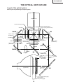
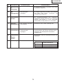
THE OPTICAL UNIT OUTLINE
Layout of the optical system
Note: Layout for positioning the optical system.
Projection Lens
Incident polarizing plate B
AR coating
emergent polarizing plate R
Dichroic coating (R transmission)
R-LCD
emergent polarizing
plate B
B-LCD
Cross dichroic prism
ct
fle
-re
or
B
ct
re
BLUE
fle
Dichroic coating
(B reflection)
M5
R
or
M4/M6
CL2
RL3
UV-filter(0.8t)
Condenser lens R
Relay lens 3
Porarizing film
emergent
polarizing plate G
G-LCD
Relay lens 2
Dichroic coating
(B reflection)
RL2
Dichroic coating
(G transmission)
Dichroic coating
(R reflection)
Porarizing film
CL3
Condenser lens G
GREEN
Marking
(Bottom)
RED
M2
G
re
fle
ct
M3
or
Relay lens 1
ct
or
RL1
fle
Dichroic coating
UV-IR coating
Marking
CL1
or
W
PBS(polarization
beam splitter)
m
irr
DC lamp
(Light source)
te
d
Ag-deposited
face
-c
Ag
or
ct
fle
re
re
B
G
BLUE
B/
M4/M6
oa
UV-filter
Fly-eye lens (outgoing light)
Fly-eye aperture
Fly-eye lens (incoming light)
19
M1
XG-C40XU/XE
CONVERGENCE AND FOCUS ADJUSTMENT
» Start the convergence and focus adjustments with the top panel removed but the power
on. Use the remote control to adjust the image.
Take the following procedures.
1. Focusing the projection lens
(A) Replacing all the 3 LCD panels
1. Before replacing all the 3 LCD panels, project an image on the screen and bring it into focus.
2. Replace the LCD panels with new ones. But until the focus has been completely readjusted, be careful not
to change the projection distance between the set and the screen, nor to move the projection lens focus
and zoom rings.
Note:
If the focus is readjusted with a different positional relation, the relation between the projection distance
and the screen size is affected. In other words, a short-distance image (40 WIDE for example) may get out
of the focus range, or a long-distance image (300 WIDE for example) may come out of the focus.
(B) Replacing 1 or 2 of the 3 LCD panels
1. In adjusting the focus after replacement of one or two LCD panels, project an image on the screen and turn
the projection lens focus ring to get the non-replaced LCD panel into focus.
2. But until the focus has been completely adjusted for the new LCD panels, be careful not to change the
projection distance between the set and the screen, nor to move the projection lens focus and zoom rings.
3. If the projection distance has been changed or the projection lens readjusted, repeat the above steps 1 and
2.
2. Focus adjustment
(A) Adjusting the G-LCD panel(Make this adjustment on the white-only screen.)
1. Adjustment in θX and Z directions .
Loosen the lock screw "a" and insert an eccentric screwdriver into the notch and hole "a". Turn the screwdriver
until the top, center and bottom on the screen get into focus. In adjusting this top-to-bottom focus, tighten
the lock screws "b" and "c" to fix the θY direction adjustment.
First get the right and left halves in balance. Then improve the accuracy while making the adjustment 2
below.
2. Adjustment in θY direction
Temporarily tighten the lock screw "a" and loosen the lock screws "b" and "c". Insert the eccentric screwdriver
into the notch and hole "c" for adjusting in the θY direction on the top of the screen. Insert the eccentric
screwdriver into the notch and hole "b" for adjusting in the θY direction on the bottom of the screen.
3. Repeat the above steps 1 and 2 to finely adjust the focus. Finally tighten up all the lock screws.
Notes :
1 Carefully proceed with the focus adjustment because the adjusting directions are correlated.
2 In adjusting the convergence and focus, do not move the projection lens zoom and focus rings until the end
of all the adjustments.
(B) Adjusting the B-LCD panel (Do the same for the R-LCD panel.)
1. Take the same procedure as for the G-LCD panel focus adjustment. Note that the adjustment range is
wider in the Z direction. If the convergence is quite different between the B-LCD and G-LCD panels,
roughly adjust the convergence first and then the focus.
3. Convergence adjustment
» Use a crosshatch pattern signal for this adjustment.
Make the adjustment just for the G-LCD and the relevant colour.
1. Loosen the convergence lock screw "d".
2. Adjustment in Y and θZ directions
Put a hex wrench in the Y and θZ direction adjustment zone.
3. Adjustment in X direction
Put an eccentric cam adjusting wrench in the X direction adjustment zone.
20
XG-C40XU/XE
4. With the G-LCD panel's screen center as refernce, adjust the R-LCD and B-LCD panels.
5. Finally tighten up the convergence lock screw "d".
Notes :
1 The eccentric cam is used for convergence adjustment.
This means that the cam's turning and the linear movement are not always uniform.
2 This model is not equipped with the LCD image adjustment mechanism. This is because the cross-dichroic
prism is used for image formation. When the LCD panels all get into best focus, the images are almost
completely converged.
Convergence and Focus Adjustments Mechanism
TOP VIEW
SIDE VIEW
Lock screw "a"
R-LCD
Notch and
hole "c"
G-LCD panel
mounting screws
(four screws)
G-LCD
Lock screw "c"
G-LCD
Lock screw "b"
Notch and
hole "b"
Lock screw "c"
Notch and hole "c"
B-LCD
Notch and hole "a"
SIDE VIEW (from outside)
SIDE VIEW (from inside)
Eccentric cam
(Y direction adjustment)
Lock screw "d"
Lock screw "d"
R·B-LCD panel
mounting screws
(four screws)
R·B-LCD
21
Eccentric cam
(X direction adjustment)
Eccentric cam
(θZ direction adjustment)
XG-C40XU/XE
Convergence and Focus Adjustments at a Glance
Adjustment directions
Adjustment
Direction
X direction
Convergence Y direction
θZ direction
Z direction
Focus
θX direction
θY direction
Definition
Direction of LCD panel
LCD right and left
LCD top and bottom
LCD turning axis
LCD optical axis
LCD top-to-bottom flapping
LCD right-to-left flapping
Rotation around Z axis
Rotation around X axis
Rotation around Y axis
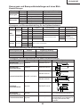
Convergence and Focus Adjustment for the Optical Mechanism
Colour
Adjustment
Direction
Movement
Position
Adjusting tool
Lock screw
Tightening tool
X direction
±0.8mm Eccentric cam
Eccentric cam adjusting wrench
d
Hex wrench
Y direction
±0.8mm Eccentric cam
Eccentric cam adjusting wrench
d
Hex wrench
R/B
θZ direction
±1°
Eccentric cam adjusting wrench
d
Hex wrench
colours
Z direction
±0.8mm Notch and hole "a" & "c" Eccentric screwdriver,
a, c
θX direction
±1°
Notch and hole "a" & "c"
a, c
θY direction
±1°
Notch and hole "b" & "c"
Phillips
screwdriver,
*Hex wrench
Z direction
±0.2mm
θX direction
±1°
θY direction
±1°
Convergence
Focus
G colour
Focus
Eccentric cam
Bladed screwdriver
b, c
Same as for R and B colours
Focus Adjustments the Other Way
Lock screw
Position
a
Notch and hole "a"
b
Notch and hole "b"
c
Notch and hole "c"
Related direction
Z and θX directions
θY direction
Z, θX and θY directions
Convergence and Focus Adjusting and Tightening Tools
Tool
Eccentric cam
adjusting wrench
Specific or General
Specific
Tool code
Configuration
9DASPN-XGNV1U
80
Eccentric screwdriver Specific
9DADRiVER-NV4U
R2
CUT
9EQLNC-XGNV1U
16
5
100
50
Hex wrench
2
General (redesigned)
92
5
7.5
9EQLNC-XGNV4U
2
0.5
2
General
—
*Hex wrench
General
—
22
ø5
Phillips screwdriver
min85
9EQDRiVER-NV1B
ø3.5
General
3.5
Bladed screwdriver
For M2.6 pan-head machine screw
1.27mm, preferably use a 70 mm or
longer screwdriver (with a handle).
XG-C40XU/XE
Replacing the LCD panels
Detach the top panel and the optical mechanism unit in advance.
(1) Remove the four prism holder lock screws. Detach the prism holder from the optical mechanism unit.
(2) Remove the LCD panel lock screws (four each for the R-, G- and B-LCD panels). Detach the LCD panels from the
prism holder.
(3) Mount a new LCD panel in the reverse order of the above steps (1) and (2).
~ Readjust the convergence and focus. Note that the G-LCD panel needs no convergence adjustment and has
a small adjustment range in the Z direction.
1
Prism holder
Optical Mechanism Unit
SIDE VIEW
SIDE VIEW (from inside)
Lock screw "d"
G-LCD
Lock screw "d"
2
R·B-LCD panel
mounting screws
R·B-LCD
23
2
G-LCD panel
mounting screws
XG-C40XU/XE
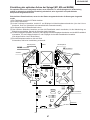
Adjusting the optical axis of the mirrors (M1, M5 and M4/M6)
The optical axis must be readjusted if an eclipse happens with the R. G or B mirrors. Generally speaking,
this adjustment is needed when any of the internal optical components has been replaced.
Adjustment procedure required when any of the panels has been replaced or the convergence has been
adjusted
(1) Disconnect the flat cables of all the LCD panels.
(2) Let the lamp light up.
(3) To adjust the G mirror, shield the R and B mirrors with shielding plates (You can use a business card or the like to
block the light).
(4) Loosen the lock screw of the M1 adjust lever.
(5) Looking at the G image on the screen, turn or slide the M1 adjust lever until the eclipse on the screen disappears.
Tighten up the screw.
(6) To adjust the R mirror, shield the G and B mirrors and adjust the M5 adjust lever. For the B mirror, shield the R and
G mirrors and adjust the M6 adjust lever.
(Take the same steps 4 and 5 above.)
(7) Remove all the shielding plates to have a white image.
Make sure there is no eclipse.
Shielding plate B
FRONT
M4/M6 adjust lever
Lock screws
Shielding plate R
M5 adjust lever
slide
turn
Lock screws
turn
slide
Shielding plate G
M1 adjust lever
turn
slide
Lock screws
24
XG-C40XU/XE
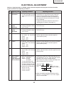
ELECTRICAL ADJUSTMENT
Hook up a signal generator, or a DOSV or Mac personal computer to the projector in order to feed the
signals specified in the Adjusting conditions.
No.
Adjusting point
Adjusting conditions
Adjusting procedure
1
EEPROM
initialization
1. Turn on the power (make » Make the following settings:
sure the lamp lights up) and
Press SW5101 to call up the process mode and
warm up the unit for 15 minexecute S2 in the SSS menu. Now the system,
utes.
with the PC board not included, is initialized. Do
not execute S1 because otherwise the PC board
will be initialized.
To adjust the PC board, follow the instruction in
"Adjusting the PC board". (See page 31)
2
3.3V power
supply
adjustment
1. Turn on the power.
» Adjust R1649 so that the voltmeter should read
2. Connect the digital voltme3.43 ±0.03 Vp-p.
ter to TP1446.
3
2.5V power
supply
adjustment
1. Turn on the power.
» Adjust R1652 so that the voltmeter should read
2. Connect the digital voltme2.60 ±0.05 Vp-p.
ter to TP1447.
4
R drive
1. Feed the 100% red-only sig- » Using the control switches or the remote controller
nal. Make the following
buttons, adjust the data so that the signal bechoice.
comes bit-less (noise).
Group : A/D
Subject : R-D
5
B drive
1. Feed the 100% blue-only » Using the control switches or the remote controller
signal. Make the following
buttons, adjust the data so that the signal bechoice.
comes bit-less (noise).
Group : A/D
Subject : B-D
6
G drive
1. Feed the 100% green-only » Using the control switches or the remote controller
signal. Make the following
buttons, adjust the data so that the signal becomes
choice.
bit-less (noise).
Group : A/D
Subject : G-D
7
RGB 1 system
1. Make the following choice: » Choose the subject G1-GAIN and adjust the sigblack level
Group : OUTPUT 1
nal amplitude to 3.3 ±0.1 Vp-p using the control
signal amplitude
Subject : G1-BLK
switches or the remote controller buttons.
(odd-numbered)
G1-GAIN
» Next,choose the subject G1-BLK and adjust the
For red, choose the subwhite to white level to 2.6 ±0.1V DC.
jects R1-BLK and R1-GAIN.
2.6V
For blue, choose the sub(Adjust to 2.6V
3.3Vp-p
jects B1-BLK and B1-GAIN.
DC for red and
(Adjust to 3.3Vp-p
blue.)
2. Connect the oscilloscope to
for green and blue.)
TP1101 for red.
TP1201 for green
TP1301 for blue
» Adjust the signal's amplitude and white to white
level to 3.3 ± 0.1Vp-p and 2.6 ± 0.1V DC, respectively, for red and blue.
25
XG-C40XU/XE
No.
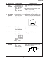
8
Adjusting point
P SIGNAL
Adjusting conditions
Adjusting procedure
1. Connect the oscilloscope to » Adjust the PSIG waveform to the one shown below.
TP1701 for red.
(Adjust with PSIG-H.)
TP1702 for green
TP1703 for blue.
PSIG
6.2±0.2V DC
2. Make the following choice:
Group : OUTPUT 2
Subject : PSIG-H
: PSIG-L
2.0V DC
GND
(Adjust with PSIG-L.)
» For the green and blue colours, make sure their waveforms are similar to that of the red colour.
» Make sure the pin stripe of every 12 dot doesn't appear at 10 steps signal of side nays.
(Appearing white pin stripe or black one, adjust the
PSIG-H.)
9
Panel ghost
adjustment
1. Project the XGA60Hz ghost » ENR-PHASE adjustment (R-LCD ghost adjustment)
test pattern (black charac1 Increase the setting until a ghost image (see
ters in bold on the halftone
Note) becomes visible at the left of the back
RGB background).
characters on the R half-tone background.
Group: OUTPUT3
2 Lower the setting point by point until the lefthand ghost image (1 above) disappears.
2. GCK-PHASE adjustment
3 Further lower the setting by one point.
Make sure the setting is fixed » ENG-PHASE adjustment (G-LCD ghost adjustat 8 (initial value).
ment)
Adjust the G ghost image by following the same
3. EN-WIDTH adjustment
procedures described under step 1 above.
Make sure the setting is fixed » ENB-PHASE adjustment (B-LCD ghost adjustat 8 (initial value).
ment)
Adjust the B ghost image by following the same
4. ENR-PHASE adjustment (Rprocedures described under step 1 above.
LCD ghost adjustment)
Note: Left-hand ghost image: Characters are shown
double 12 dots left from the real characters.
5. ENG-PHASE adjustment Reference: This adjustment is made because the
(G-LCD ghost adjustment)
EPSON LCD panel may have 1- or 2point differences due to lot-by-lot varia6. ENB-PHASE adjustment (Btions.
LCD ghost adjustment)
10
Sample-andhold pulse
phase
RCK-PHASE
GCK-PHASE
BCK-PHASE
1. Feed the XGA mode 75-Hz » Using the control switches or the remote controller
black signal.
buttons, make sure that the “OUTPUT 3” charac2. Make the following choice:
ters are not blurry and there is no ghost image. If
Group : OUTPUT 3
such blur or ghost occurs, finely adjust the setting
Subject : SH-PHASE
in the range of 7~9.
(Have the standard level at
2.)
Fix the RCK-, GCK- and
BCK-PHASE settings all to
8.
26
XG-C40XU/XE
No.
Adjusting point
Adjusting conditions
Adjusting procedure
11
RGB countervoltage
adjustment
1. Feed the black-and-red » Using the control switches or the remote controller
(25%) stripe signal (XGA).
buttons, adjust the data in order to minimize the
2. Make the following choice:
flicker.
Group : OUTPUT 3
Subject : RC (R)
» Make the same adjustment for BC (B), GC (G),
and
RC-INV (B) and RC-INV (G).
Group : OUTPUT 3
Subject : RC-INV (R)
» See if the image is equally adjusted at the center
and both sides of the screen. If not, readjust the
setting to have the image equal at right and left.
12
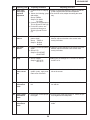
RGB gradation
regeneration
adjustment
1. Feed the green-only SMPTE » Adjust the G-BLK data until the gradation of the
pattern signal (XGA).
portion 1 (95% and 100% white) shown below
Group : OUTPUT 1
can be slightly recognized. Make sure also that the
Subject : G1-BLK
gradation of the portion 2 (0% and 5% black) is
visible.
2
1
13
RGB white
balance
1. Feed the 32-step gray scale » Choose the subjects R1-BLK and B1-BLK and
signal (XGA).
adjust the black balance of the gradation.
Group : OUTPUT 1
Subject : R1-BLK (R)
B1-BLK (B)
14
Horizontal
center
1. Feed the NTSC monoscope » Using the control switches or the remote controller
pattern signal.
buttons, adjust the data to have the same
2. Group : VIDEO 2
overscan.
Subject : N358-DLY (4)
N443-DLY (0)
PAL-DLY
(3)
SECAM-DLY (0)
Make sure the settings are
as above.
3. Group : VIDEO 1
Subject : NTSC-H
15
Video picture
adjustment
1. Feed the split colour bar sig- » Using the control switches or the remote controller
nal.
buttons, adjust the black-to-white (100%) level
Group : VIDEO 1
difference to 2.0 ±0.02 Vp-p.
Subject : PICTURE
2. Connect the oscilloscope
between pin (2) of P801 and
2.0Vp-p
GND.
27
XG-C40XU/XE
No.
Adjusting point
Adjusting conditions
Adjusting procedure
16
Video
brightness
adjustment
1. Feed the baseband (split » Using the control switches or the remote controller
colour bar) signal. (The ONbuttons, adjust the setting until the black signal
AIR signal is not accepted
becomes bit-less.
because of its too much
noise.)
Group : VIDEO 2
Subject : VROS/VGOS/VBOS
2. Press the control switch or
the remote control’s mute
button (to set the gamma
correction to the process
setting).
17
Video AGC
1. Feed the split colour bar signal. » Using the control switches or the remote controller
Group : VIDEO 1
buttons, adjust the setting until the white signal
Subject : AGC
becomes bit-less.
18
Tint
1. Feed the split colour bar
signal.
Group : VIDEO 1
Subject : TINT
2. Connect the oscilloscope to
pin (4) of P801.
» Using the control switches or the remote controller
buttons, adjust the data to have the -(B-Y) waveform downhill straight.
» After adjusting, adjust the
value of TINT up 3 point.
19
NTSC colour
saturation level
1. Feed the split colour bar sig- » Using the control switches or the remote controller
nal.
buttons, adjust the difference between the 100%
Group : VIDEO 1
white portion and the red portion to 0.00 ±0.05 Vp-p.
Subject : N-COLOR
(same as 100% white)
2. Connect the oscilloscope to
100% White Red
pin (1) of P801.
20
PAL colour
saturation level
1. Feed the PAL colour bar sig- » Using the control switches or the remote controller
nal.
buttons, adjust the difference between the 100%
Group : VIDEO 1
white portion and the red portion to 0.2 ±0.05 Vp-p.
Subject : P-COLOR
100% White Red
2. Connect the oscilloscope to
pin (1) of P801.
21
SECAM colour
saturation level
1. Feed the SECAM colour bar » Using the control switches or the remote controller
signal.
buttons, adjust the data to have a level difference
Group : VIDEO 1
of 0.2 ±0.05 Vp-p between the 100% white portion
Subject : S-COLOR
and the red portion.
2. Connect the oscilloscope to
100% White Red
pin (1) of P801.
28
XG-C40XU/XE
No.
Adjusting point
Adjusting conditions
Adjusting procedure
22
Video input
panel signal
amplitude
adjustment
1. Feed the NTSC 10-step sig- » Select R1-GAIN and adjust the setting so that the
nal.
R and G signals have the same amplitude.
2. Select the following group » For the blue colour, adjust the setting the same
and subject.
way.
Group: VIDEO2
Subject: R1-GAIN
B1-GAIN
3. Connect the oscilloscope to
TP1101 (R) and TP1201 (G).
4. For the blue colour, connect the oscilloscope to
TP1301 (B) and TP1201
(G).
23
Video white
balance
1. Feed the NTSC monoscope » Using the control switches or the remote controller
pattern signal
buttons, adjust so that the entire screen looks
Group : VIDEO 2
evenly colourless.
Subject : R1-BLK
B1-BLK
24
DTV white
balance
1. Feed the monoscope pattern » Using the control switches or the remote controller
buttons, adjust so that the entire screen looks
signal.
evenly colourless.
2. Group: DTV
Subject: CR-OFFSET
CB-OFFSET
25
Setup
1. Group: VIDEO1
Subject: SET UP B
SET UP C
26
Automatic
colour correction
1. Using the colour correction » Make sure there is no noticeable colour irregularity
system (ccdc), apply autoleft on the screen.
matic colour correction.
27
Colour system
performance
check
1. Receive the colour bar sig- » In the process mode and select L1. Check the colnal.
our and tint.
28
Video system
performance
check
1. Receive the monoscope pat- » In the process mode and select L2. Check the pictern signal.
ture, brightness and sharpness.
29
Audio system
performance
check
» In the process mode nad select L3. Check the bass,
treble.
» Make sure the settings are 11 for SET UP B and 2
for SET UP C.
29
XG-C40XU/XE
No.
Adjusting point
Adjusting conditions
30
RGB
performance
check
31
Off-timer
performance
check
32
Thermistor
performance
check
1. Heat the thermistor using a » Make sure the “TEMP” is displayed.
dryer.
33
Automatic
synchronization
1. Receive the PHASE check » Call the VGA/SVGA/XGA/SXGA mode and make
pattern signal.
sure that the clock, phase, horizontal and vertical
positions can be automatically adjusted.
34
Keystone
correction
performance
check
» Make sure the keystone correction functions well.
35
Factory settings
» Make the following settings.
1. Receive the RGB signal.
Adjusting procedure
» In the process mode and select L4. Check the picture, brightness, red, blue, clock, phase, horizontal
position, and vertical position.
» In the process mode and select OFF. Make sure that
the off-timer starts with “5” (minutes), counts down each
minute in 1 second, and turns off the set at “0”.
Process
adjustment
S3
S4
30
Remote controller setting
“Factory setting 3”(XG-C40XE)
“Factory setting 4”(XG-C40XU)
XG-C40XU/XE
ADJUSTING THE PC BOARD (CPCi-0047CE15/16. PC I/F Unit)
1. RGB level adjustment
1) Connect a signal generator to the projector that is equipped with the 0047 PWB. Set the signal generator
output to the XGA mode (VESA1024x768, 60Hz, 32-tone waveform). Adjust the output amplitude to 700
mVp-p at the P8404 connector.
2) Set the projector input to the RGB1 mode.
3) Using a pushbutton on the projector, call the process mode.
4) On the main menu screen, select the group “A/D”.
5) Select the subject “R-BRIGHT” in the group “A/D” and adjust the “R-BRIGHT” setting so that there should be
no bits around the screen.
6) Do the same with the “G-BRIGHT” and “B-BRIGHT” settings.
7) Next select the group “R-D” and the settings of the above subjects so that there should be no bits around the
screen.
8) Then select the groups “G-D” and “B-D” and make the same adjustments.
Now let’s go to the DTV level adjustment.
2. DTV level adjustment
1) Set the signal generator output to the green-only mode.
2) On the main menu screen of the process mode, select the group “DTV”.
3) Select the subject “G-BRIGHT” in the group “DTV” and adjust the “G-BRIGHT” setting so that there should be
no bits around the screen.
4) Do the same with the “CB-OFFSET” and “CR-OFFSET” settings.
Now the 0047 PWB on the projector is adjusted for delivery.
Note: There is no need to make the VIDEO input adjustments.
Servicing precautions
If the convergence gets out of spec in servicing the set, call the process mode and select the following group and
subjects.
Group: NOKO
Subject: R-CNV-H, R-CNV-V
G-CNV-H, G-CNV-V
B-CNV-H, B-CNV-V
(H and V are for horizontal and vertical adjustments, respectively.)
Adjust the above settings to the range of 0 to 4.
31
XG-C40XU/XE
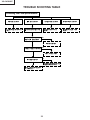
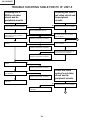
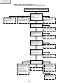
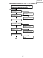
TROUBLE SHOOTING TABLE
Checking the PWB performance
Video input in trouble
RGB input in trouble
Through-output in trouble
Remote control in trouble
Go to "Checking the video unit
Feed test pattern signal from
Through-output circuit in
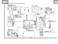
Go to "Checking the remote
circuit".
PC.
trouble.
control".
Is specified cable connected
No
between PC and projector?
Yes
Use specified cable.
Is supply voltage as specified?
No
Yes
Power circuit in trouble.
Does image appear?
No
Yes
Check the connectors, starting
from the PC input circuit.
Go to "Trouble shooting table
for PC I/F unit ".
32
XG-C40XU/XE
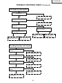
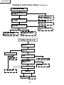
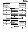
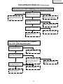
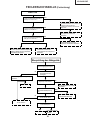
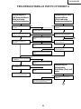
TROUBLE SHOOTING TABLE (Continued)
Checking the video system
No
Is the lamp on?
Yes
Go to "Lamp fails to light-up".
No
Is specified voltage fed to EA
connectors?
Yes
Check the power circuit and its parts.
Are there signal inputs at pins (3) and
(29) of P402?
No
Yes
Are there signals at pin (4) of IC401
and pin (4) of IC402?
Are there signal outputs at pins (3)
and (6) of IC816?
Yes
Yes
No
Go to "Checking IC801
(RGB signal output circuit)".
Check IC816, IC806 and
their peripheral circuits as
well as switching circuit.
Check the video unit circuit
(IC6004 and its peripheral
circuits).
Checking the video unit circuit
Is there video signal output at pin (7)
of IC6001?
No
Yes
Is there video signal input at IC6004?
Check the IC6001 selector switch,
terminal voltage and input circuit.
No
Yes
Are there signal outputs at pins (6)
and (8) of IC6004?
Check the low-pass and buffer
circuits of Q6009 thru Q6015.
No
Yes
Check IC6004 and its peripheral
circuits (bias).
Check the low-pass and buffer circuits No
of Q6002 thru Q6008. Is the signal as
specified?
Yes
Check Q6002 thru Q6008 and their
peripheral circuits.
Go to "Checking IC801 (RGB signal
output circuit)".
33
No
Check the oscillation circuit
of IC401 and IC402, and
their peripheral circuits.
XG-C40XU/XE
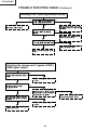
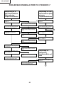
TROUBLE SHOOTING TABLE (Continued)
Checking IC801 (RGB signal output circuit)
No
Are there RGB output waveforms at
No
pins (31), (32) and (33) of IC801?
Yes
Go to "No colour or unusual tone",
Check the data transfer and other
"No Y signal" or "Out of sync".
performance at pins (17) and (18) of
Are there output waveforms at the
emitters of Q1501, Q1502 and
video IC801.
No
Q1503?
Yes
Check Q1501 thru Q1503, SC1501
and their peripheral circuits.
Are there output waveforms at the
No
emitter of Q1505, Q1506 and Q1507?
Yes
Check IC1501, Q1505 thru Q1507
and their peripheral circuits.
Go to "Trouble shooting table for PC
I/F unit".
Checking the chroma and Y signals of IC801
(RGB signal output)
Are there signal inputs at pins (12)
No
(Y signal) and (19)(chroma signal) of
P402?
Go to "Checking the video unit
Yes
circuit".
Are there output waveforms at pins
(3)(chroma signal) and (6)
No
(Y signal)of IC816?
Check the
Yes
IC816 switching and their
peripheral circuits. If there is no signal
at pins (9) and (1) of IC816, check 3-D
noise reduction circuit (IC806).
Are there signal inputs at pins (20)
(chroma signal) and (21) (Y signal)
of IC801?
Yes
Check IC801 and its peripheral
circuits.
Go
to
"Checking
IC801
Check IC806 (3-D noise reduction
circuit) and its peripheral circuits.
No
(RGB
signal output circuit)".
34
XG-C40XU/XE
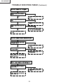
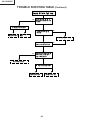
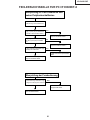
TROUBLE SHOOTING TABLE (Continued)
Checking IC806 (3-D noise reduction circuit)
and its peripheral circuits
Are there signal inputs at pins (40)
(Y signal) and (45)(chroma signal) of
No
IC806?
Yes
Check the buffer circuit of Q814 thru
Q816 as well as Q903 thru Q906.
Are there signal outputs at pins (55)
No
(Y signal) and (51)(chroma signal) of
IC806?
Yes
Check IC806, IC807 (memory) and
their peripheral circuits.
Are there signal outputs at the
emitters of Q817 (Y signal) and Q910
No
(chroma signal)?
Yes
Check the low-pass circuit around
Q817, Q907 and Q910.
Check IC816 and IC801 (RGB signal
output circuit).
No colour or unusual tone (NTSC, PAL)
Is there chroma signal input at pin
No
(20) of IC801?
Yes
Go back to the signal processing
block.
Are there signal outputs at pins
No
(46)(R-Y) and (45)(B-Y) of IC801?
Yes
Check the oscillation of X801 and
X802, and their peripheral circuits.
Check IC803, IC814 and their
peripheral circuits.
35
XG-C40XU/XE
TROUBLE SHOOTING TABLE (Continued)
No or unusual Y signal
Is there Y signal input at pin (21) of
No
IC801?
Yes
Go back to the signal processing
block.
Is there Y signal output at pin (40) of
No
IC801?
Yes
Check IC801 and its peripheral
circuits.
Is there Y signal output at pin (17) of
No
IC803?
Yes
Check IC803 and its peripheral
circuits as well as IC805 (AGC).
Check IC803 and its peripheral
circuits.
No or unusual horizontal sync
Is there horizontal sync pulse output
No
at pin (56) of IC801?
Yes
Check IC801 and its peripheral
circuits.
Is there horizontal sync pulse output
No
at pin (9) of IC603?
Yes
Check the pulse shaping circuit of
IC602 and IC603.
Check
IC604
and
its
peripheral
circuits, and go to "Trouble shooting
table for PC I/F unit".
No or unusual vertical sync
Is there vertical sync pulse output at
No
pin (4) of IC801?
Yes
Check IC801 and its peripheral
circuits.
Check
IC604
and
its
peripheral
circuits, and go to "Trouble shooting
table for PC I/F unit".
36
XG-C40XU/XE
TROUBLE SHOOTING TABLE (Continued)
Checking the output PWB unit
No
Are there signal inputs at
SC1404, SC1405, SC1501 and
No
SC1502?
Are voltages applied to EA
If there is no signal at SC1501
If there is no signal at SC1404
and SC1502, go to the video
and SC1405, go to "Trouble
system block.
shooting table for PC I/F unit".
connectors and SC5502?
Yes
Are there signal outputs at
pins (14) ,(16) and (18) of
If there is no signal at EA
connector or SC5502, go to
Checking the power unitblock.
No
IC1401 ?
Yes
Check IC1401 and their
peripheral circuits.
Are there signal inputs at pin
No
(47) of IC1101, IC1201 and
IC1301?
Check IC1401 and their
Yes
peripheral circuits.
Are there signal outputs at pins
(17), (19), (21), (28), (30) and
No
(32) of IC1101, IC1201 and
IC1301?
Check IC1101,IC1201,IC1301
Yes
and their peripheral circuits.
Are there signal outputs at pins
(17), (19), (21), (28), (30) and
No
(32) of IC1102, IC1202 and
IC1302?
Check IC1102,IC1202,IC1302
Yes
No
Are there signal inputs at
SC1101, SC1201 and
SC1301?
If there is no signal input at
Yes
Yes
and their peripheral circuits.
No
If there is no signal input at
pins (1) and (31) of SC1101,
pins (15) and (30) of
SC1102 and SC1103, check
SC1101, SC1102 and
the switching circuit and
SC1103, check IC1409
amplifier circuit of IC1101,
Check the R, G and B panels.
IC1201, IC1301, IC1102,
and their peripheral
circuits.
IC1202, IC1302 and their
peripheral circuits.
Check IC1106, IC1206,
IC1306, IC1408 and their
peripheral circuits.
37
XG-C40XU/XE
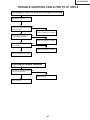
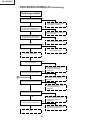
TROUBLE SHOOTING TABLE (Continued)
No audio output
Are there audio signal inputs at pin
No
(2) of IC1411?
Yes
Check the input, the switching circuit
of IC3303 and IC3304, and their
peripheral circuit,SC3001,SC1502,etc.
Are there audio signal outputs at pin
No
(2) of P5508?
Yes
Check the IC1411 control voltage,and
its peripheral circuits.
Are there audio signal outputs at pin
No
(6) of IC7301?
Yes
Check IC7301 and its peripheral
circuits.
If the voltage at pin (2) of IC7301 is
Check IC7301 and its peripheral
not as specified, check Q5501,
circuits, and the SP connectors and
Q5502 and their peripheral circuits.
speakers.
Checkig the Power Unit
There is no voltage output at
EA connector.
Yes
Is there any other output
voltage failure?
No
Which output voltage line fails?
6.7V
Is EA connector disconnected
Yes
or loose?
No
Replace ICP751.
Reconnect the EA connector.
Is AC voltage (85-264V)
No
applied across the PA
connector?
Yes
Replace F701 or Check
Bimetal SW.
Yes
Is TF701 open?
No
Replace TF701.
Is R706 open?
No
Yes
Replace R700.
Replace Power
unit.
38
XG-C40XU/XE
TROUBLE SHOOTING TABLE (Continued)
Power on
Is the right input selected?
No
Yes
Select the right input with remote
control.
Are the PC, video and LCP cables as
No
specified and properly connected?
Yes
Use the right cables or reconnect the
cables.
With the contrast control at maximum,
Yes
does the image appear?
No
Readjust the video system.
Is the voltage at CON3 (P8502)
No
connector as specified?
Yes
Power circuit faulty.
Hook up a personal computer.
Does the image appear?
No
Yes
Go to "Checking the clock circuit and
its peripheral circuits".
Is the image as specified?
No
Yes
Check the sync signal circuit and its
A
peripheral circuits.
Is the image's colour as specified?
No
Yes
Check the video circuit and its
peripheral circuits.
Does the on-screen display function?
No
Yes
Go to "Checking the OSD circuit and
its peripheral circuits".
Does the remote control function?
No
Yes
Go to "Checking the remote control".
End
39
XG-C40XU/XE
TROUBLE SHOOTING TABLE (Continued)
Lamp fails to light-up
Yes
Turn on the power switch. Is
discharging sound heard from
the lamp?
No
Is the lamp out of socket?
Yes
No
Is the ballast cooling fan
No
running?
Reconnect the
Replace the
lamp into socket.
lamp.
Yes
Check the power circuit.
Is DC 360V voltage applied
No
between PL connector pins?
Yes
Yes
Is 2V or higher voltage applied
between pins (1) and (2) of
ballast's D connector?
No
Replace the ballast.
Is D connector disconnected?
No
Yes
Reconnect the
Check the
connector into socket.
microcomputer circuit.
40
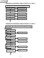
XG-C40XU/XE
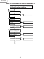
TROUBLE SHOOTING TABLE FOR PC I/F UNIT-1
Power On
Is the input properly selected?
No
Select the specified input with the
remote controller.
Yes
Are the PC, video and projector
cables as specified and properly
connected?
No
Use the specified cables. Reconnect
them correctly.
Yes
Turn up the contrast control all the
way. Is the image visible?
Yes
Readjust the video settings.
No
Is the voltage at connector P8502 as
specified?
No
Power circuit defective.
Yes
Is the image invisible?
Yes
Go to “Checking the Clock Circuit
and its Peripheral Circuits”.
No
Is the image distorted?
Yes
Go to “Checking the Sync Signal
Circuit and its Peripheral Circuits”.
No
Are the image colors abnormal?
4
Yes
Go to “Checking the Video Circuit
and its Peripheral Circuits”.
No
Yes
Does the onscreen display
malfunction?
Go to “Checking the OSD Circuit and
its Peripheral Circuits”.
No
Yes
Does the remote controller
malfunction?
Go to “Checking the Remote
Controller”.
No
End
41
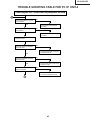
XG-C40XU/XE
TROUBLE SHOOTING TABLE FOR PC I/F UNIT-2
Checking the clock circuit and its peripheral circuits
Is X8001 (6MHz) oscillating?
No
X8001 or its peripheral part faulty.
Yes
Is X8003 (1.84MHz) oscillating?
No
X8003 or its peripheral part faulty.
Yes
Is X8004 (22.165MHz) oscillating?
No
X8004 or its peripheral part faulty.
Yes
Is X8005 (18.75MHz) oscillating?
No
X8005 or its peripheral part faulty.
Yes
Does pin (162) of IC8001 function?
No
IC8001 or its peripheral circuit faulty.
Yes
5
TROUBLE SHOOTING TABLE FOR PC I/F UNIT-3
Checking the Sync Signal Circuit and its Peripheral Circuits
5
No
Is the sync signal of split type?
Yes
Are there signals at TP8004 and
TP8005?
No
IC8610 or terminal PWB defective.
Yes
No
Is the sync signal of Sync On Green
type?
Yes
No
Are there signals at pin (7) of IC8611?
IC8611 or its peripheral part faulty.
Yes
Are there signals at pins (149) (TL80
34) and (150) (TL8035) of IC8020?
No
IC8025 or its peripheral part faulty.
Yes
No
Does the input have a resolution lower
than XGA or is it video input?
Yes
Are there signals at pins (26) (TL8043), No
(28) (TL8041) and (29) (TL8042) of
IC8020?
IC8020 or its peripheral part faulty.
Yes
Are there signals at pins (13) thru
(52), except for GND, of P8405?
No
IC8029,IC8609 or its peripheral
part faulty.
Yes
6
42
XG-C40XU/XE
TROUBLE SHOOTING TABLE FOR PC I/F UNIT-4
Checking the PLL circuit and its peripheral circuits
6
Are there signal at pins (111) and
(112) of IC8606?
No
Yes
Are there signals at pins (7) and
(10) of IC8601?
IC8025,IC8600 or its peripheral
circuit faulty.
No
Yes
IC8601,IC8606 or its peripheral
circuit faulty.
Check the video circuit and its
peripheral circuits.
Is image as specified at resolution
above XGA level?
No
Check the S-XGA video circuit and
its peripheral circuits.
Yes
Is image as specified at resolution
below XGA level?
No
Check the VGA video circuit and its
peripheral circuits.
Yes
Hook up a video system. Is the
display as specified?
Yes
No
Check the video system's video
circuit and its peripheral circuits.
4
43
XG-C40XU/XE
TROUBLE SHOOTING TABLE FOR PC I/F UNIT-5
Checking the SXGA's red video
circuit and its
peripheral circuits
Is there signal at pin (139) of IC8606?
Checking the VGA's
red video circuit and
its peripheral
circuits
No
Yes
Are there signals at pins (21) thru (31)
as well as (34) thru (41), except for
GND, of P8606?
Is there signal at pin (139) of IC8606?
Yes
Terminal PWB,C8616 defective.
No
Yes
Are there signals at TL8044 and
TL8046?
No
No
Are there signals at pins (21) thru (31)
as well as (34) thru (41), except for
GND, of P8606?
Yes
IC8606 or its peripheral circuit faulty.
No
No
Are there signals at pins (112) thru
(119) of IC8020?
Yes
Yes
IC8025 or its peripheral circuit faulty.
No
Are there signals at pins (69) thru (73)
and (189) thru (192) of IC8020?
Yes
IC8020 or its peripheral circuit faulty.
Is there signal at pin (Y11)(TL8612) of
IC8609?
No
Yes
Are there signals at pins (1) thru
(10) of IC8051?
Yes
IC8029 or its peripheral circuit faulty.
Check the video
system's red video
circuit and its
peripheral circuits
No
IC8609 or its peripheral circuit faulty.
IC8051 or its peripheral circuit or output
PWB faulty.
No
Is there signal at pin (144) of IC8606?
Yes
C8702 or its peripheral circuit or signal
PWB faulty.
1
44
1
XG-C40XU/XE
TROUBLE SHOOTING TABLE FOR PC I/F UNIT-6
Checking the SXGA's green video
circuit and its
peripheral circuits
Is there signal at pin (124) of IC8606?
Checking the VGA's
green video circuit
and its peripheral
circuits
No
No
Is there signal at pin (124) of IC8606?
Yes
Yes
Terminal PWB, C8620 defective.
Are there signals at pins (68) thru (75)
as well as (78) thru (88), except for
GND, of P8606?
No
Yes
Are there signals at TL8045 and
TL8047?
No
IC8606 or its peripheral circuit faulty.
No
No
Are there signals at pins (68) thru (75)
as well as (78) thru (88), except for
GND, of P8606?
Yes
Are there signals at pins (165) thru
(177) of IC8020?
Yes
Yes
IC8025 or its peripheral circuit faulty.
No
Are there signals at pins (178) thru (187)
of IC8020?
Yes
IC8020 or its peripheral circuit faulty.
Is there signal at pin (V13)(TL8613) of
IC8609?
No
Yes
Are there signals at pins (11) thru
(20) of IC8051?
Yes
IC8029 or its peripheral circuit faulty.
Check the video
system's green
video circuit and its
peripheral circuits
No
IC8609 or its peripheral circuit faulty.
IC8051 or its peripheral circuit or output
PWB faulty.
No
Is there signal at pin (126) of IC8606?
Yes
C8703 or its peripheral circuit or signal
PWB faulty.
1
45
1
XG-C40XU/XE
TROUBLE SHOOTING TABLE FOR PC I/F UNIT-7
Checking the SXGA's blue video
circuit and its
peripheral circuits
Is there signal at pin (133) of IC8606?
Checking the VGA's
blue video circuit
and its peripheral
circuits
No
No
Is there signal at pin (133) of IC8606?
Yes
Yes
Terminal PWB, C8623 defective.
Are there signals at pins (45) thru (53)
as well as (56) thru (64), except for
GND, of P8606?
No
Yes
Are there signals at TL8048 and
TL8049?
No
IC8606 or its peripheral circuit faulty.
No
No
Are there signals at pins (45) thru (53)
as well as (56) thru (64), except for
GND, of P8606?
Yes
Are there signals at pins (85) thru
(93) of IC8020?
Yes
Yes
IC8025 or its peripheral circuit faulty.
No
Are there signals at pins (74) thru (83)
of IC8020?
Yes
IC8020 or its peripheral circuit faulty.
Is there signal at pin (U15)(TL8614) of
IC8609?
No
Yes
Are there signals at pins (21) thru
(30) of IC8051?
Yes
IC8029 or its peripheral circuit faulty.
Check the video
system's blue video
circuit and its
peripheral circuits
No
IC8609 or its peripheral circuit faulty.
IC8051 or its peripheral circuit or output
PWB faulty.
No
Is there signal at pin (136) of IC8606?
Yes
C8704 or its peripheral circuit or signal
PWB faulty.
1
46
1
XG-C40XU/XE
TROUBLE SHOOTING TABLE FOR PC I/F UNIT-8
Checking the OSD circuit and its peripheral circuits
Display OSD on the screen.
No
Are there signals at pins (56), (58),
(71) and (72) (TL8054,TL8053,TL8052,
TL8051) of IC8048?
Yes
Are there signals at pins (12), (14)
thru (17) and (20) of IC8046?
IC8029 or its peripheral circuit faulty.
No
Yes
IC8048 or its peripheral circuit faulty.
Are there signals at pins (23) thru
(42) of IC8046?
No
Yes
IC8046 or its peripheral circuit faulty.
IC8048 or its peripheral circuit faulty.
Checking the remote controllor
Use the remote controller. Is there the
signal at pin (59) of P8405?
No
Yes
Output PWB faulty.
IC8001 circuit faulty.
47
XG-C40XU/XE
Technische Daten
Produkttyp
Modell
Videosystem
Wiedergabeverfahren
LCD-Projektionspaneel
Objektiv
Projektionslampe
Kontrastverhältnis
Videoeingangssignal
S-Videoeingangssignal
Horizontale Auflösung
Audioausgang
RGB-Computereingangssignal
Punktetakt
Vertikale Frequenz
Horizontale Frequenz
Computereingangs-Signal
Lautsprechersystem
Nennspannung
Eingangsspannung
Nennfrequenz
Nennaufnahme
Betriebstemperatur
Lagertemperatur
Gehäuse
I/R-Trägerfrequenz
Laserzeiger der Fernbedienung
Abmessungen (ca.)
Gewicht (ca.)
Mitgeliefertes Zubehör
LCD Projector
XG-C40XE
PAL/SECAM/NTSC 3.58/NTSC 4.43/DTV 480P/DTV 720P/DTV 1080I
LCD-Projektionspaneel × 3, optisches RGB-Verschlußverfahren
Panelgröße: 22,9 mm (0,9) (13,9 mm [H] × 18,5 mm [B])
Wiedergabe-Verfahren: Durchlässiges TN-Flüssigkristall-Paneel
Treiberverfahren: TFT (Dünnfilmtransistor) Aktivmatrix-Paneel
Anzahl der Bildpunkte: 786.432 Bildpunkte (1.024 [H] × 768 [V])
1–1,3 Zoomobjektiv, F1,7–2,0, f = 33–43 mm
200 W Gleichstrom-Lampe
250:1
RCA-Stecker: VIDEO, Gemischtes Video, 1,0 Vs-s, negatives Sync.-Signal, 75 Ω
terminiert
RCA-Stecker: AUDIO, 0,5 Vrms mehr als 22 kΩ (Stereo)
4-Pin Mini DIN-Stecker
Y (Luminanz-Signal): 1,0 Vs-s, negatives Sync.-Signal, 75 Ω terminiert
C (Chrominanz-Signal): Stoß 0,286 Vs-s, 75 Ω terminiert
560 Fernsehzeilen (Videoeingang), 750 Fernsehzeilen (DTV 720P-Eingang, Punkt für
Punkt)
3 W (monaural)
15-PIN MINI D-SUB STECKANSCHLUSS (INPUT 1, 2):
RGB getrennt/gemischte Sync./Sync. auf Grün-Typ analoger Eingang: 0–0,7 Vs-s,
positiv, 75 Ω terminiert
STEREO-MINIBUCHSE: AUDIO, 0,5 Vrms, mehr als 22 kΩ (Stereo)
HORIZONTALES SYNC.-SIGNAL: TTL-Pegelsignal (positiv/negativ) oder gemischtes Sync.Signal (nur Macintosh)
VERTIKALES SYNC.-SIGNAL: Wie oben
12–230 MHz
43–200 Hz
15–126 kHz
9-Pin Mini DIN-Steckanschluß (RS-232C-Eingangsanschluß)
8 cm (3 3⁄32) rund
AC 100–240 V
3,3 A
50/60 Hz
300 W
+ 5°C bis + 40°C
– 20°C bis + 60°C
Kunststoff
38 kHz
Wellenlänge: 650 nm / Max. Ausgang: 1 mW / Klasse II Lasergerät
229 × 121 × 310 mm (B × H × T) (nur Hauptgerät)
243,5 × 134 × 358,4 mm (B × H × T) (einschließlich Drehfüße und vorstehende Teile)
4,8 kg
Fernbedienung, Zwei Batterien der Größe AA, Netzkabel (1,8 m), RGBComputerkabel (3m), Computer-Audiokabel (3 m), USB-Maus-Steuerungskabel (1,5 m),
DIN-D-Sub RS-232C-Kabel (15 cm),Fernbedienungs-Mausempfänger, Ersatz-Luftfilter,
Objektivkappe (angebracht), CD-ROM, Bedienungsanleitung für LCD-Projektor,
Kurzreferenz für LCD-Projektor,Software-Anleitung für Sharp Advanced Presentation
Ersatzteile Lampensatz (Lampe/Käfigmodul) (BQC-XGC40XU/1), Fernbedienung
(RRMCG1584CESA), Batterien der Größe AA, Netzkabel (QACCB5024CENA,
QACCV4002CEZZ), RGB-Computerkabel(QCNWG0002CEZZ), Computer-Audiokabel
(QCNW-4870CEZZ),USB-Maus-Steuerungskabel (QCNWG0007CEPZ), DIN-D-Sub
RS-232C-Kabel (QCNW-5288CEZZ), Fernbedienungs-Mausempfänger (RUNTK0673
CEZZ), Luftfilter (PFILD0076CEZZ), Objektivkappe(GCOVH1307CESB), CD-ROM
(UDSKA0057CEN1), Bedienungsanleitung für LCD-Projektor (TINS-7533CEZZ),
Kurzreferenz für LCD-Projektor (TINS-7534CEZZ, TINS-7535CEZZ, TINS-7536CEZZ),
Software-Anleitung für Sharp Advanced Presentation(TINS-7537CEZZ)
Dieser Projektor von SHARP ist mit 3 LCD- (Flüssigkristallanzeige)
Projektionspaneels ausgestattet. Diese neuartigen Projektionspaneels
enthalten TFTs (Dünnfilmtransistoren) mit insgesamt 786.432
Bildpunkten (× RGB). Bei allen technologisch fortschrittlichen,
elektronischen Geräten, z. B. Großbild-Fernsehern, Videosystemen
bzw. Videokameras, sind bestimmte Toleranzgrenzen für die
Funktionen gegeben.
Dieses Gerät hat einige inaktive, innerhalb akzeptierter
Toleranzgrenzen liegende TFTs, die als beleuchtete oder als nicht
aktive Punkte auf der Bildwand wiedergegeben werden. Dies hat
keinen Einfluß auf die Bildqualität und die Lebensdauer des Gerätes.
Änderungen der technischen Daten ohne vorherige Ankündigung vorbehalten.
48
XG-C40XU/XE
HINWEIS FÜR DAS WARTUNGSPERSONAL
1234567890123456789012345678901212345678901234
1234567890123456789012345678901212345678901234
1234567890123456789012345678901212345678901234
Ë Auswechseln der Lampe
1234567890123456789012345678901212345678901234
ACHTUNG: UV-STRAHLUNG
1234567890123456789012345678901212345678901234
1234567890123456789012345678901212345678901234
Hinweis:
Da die Lampe während des Betriebs sehr heiß wird,
sollte die Lampe erst ausgewechselt werden, nachdem
das Gerät mindestens eine Stunde ausgeschaltet war,
damit die Lampe ausreichend abkühlen kann.
Beim Installieren der neuen Lampe muß darauf
geachtet werden, die Lampe selbst (Glaskolben)
nicht zu berühren. Vielmehr muß die Lampe am
Reflektor 2 gehalten werden.
[Es darf nur ein Original-Ersatzteil verwendet
werden.]
Die Lichtquelle im LCD-Projektor, eine MetallHalogen-Lampe, gibt eine geringe UV-Strahlung ab.
DIREKTE BESTRAHLUNG AUF AUGEN
UND HAUT MUSS VERMIEDEN WERDEN.
Zur Gewährleistung der Sicherheit muß folgendes
beachtet werden:
1. Bei Arbeiten am Projektor bei eingeschalteter
Lampe und abgenommenem oberen Gehäuse
muß unbedingt eine Sonnenbrille getragen
werden.
1 Lampe
2 Reflektor
GEFAHR! — Niemals die Spannungsversorgung
einschalten, ohne daß eine Lampe vorhanden ist,
um elektrische Schläge und Schäden am Gerät zu
vermeiden, da der Stabilisator anfangs hohe
Spannungen erzeugt.
2. Die Lampe darf nicht außerhalb des
Lampengehäuses eingeschaltet werden.
Da eine geringe UV-Strahlung aus einer Öffnung
zwischen der Schachtabdeckung und dem
Lampengehäuse austritt, sollte der Objektivdeckel
bei Wartungsarbeiten auf die Öffnung gesetzt
werden, um die Bestrahlung von Augen und Haut
zu vermeiden (Abb. 1).
3. Betrieb für länger als 2 Stunden bei
abgenommenem Gehäuse ist nicht zulässig.
Hinweis: Besorgen Sie sich einen Objektivdeckel,
bevor Sie Arbeiten an einem Modell XGC40XE durchführen, das keinen
Objektivdeckel aufweist.
Objectivdeckel
Zur Beachtung bei UV-Strahlung
und Mitteldruck-Lampen
1. Vor dem Auswechseln der Lampe muß der
Netzstecker gezogen werden.
2. Vor Durchführung von Wartungsarbeiten muß das
Gerät eine Stunde abkühlen.
3. Nur mit dem gleichen Lampentyp ersetzen Typ
CLMPF0075CE01 oder BQC-XGC40XU/1;
Nennleistung 85 V / 200 W.
4. Die Lampe gibt eine geringe UV-Strahlung ab,
daher muß direkter Augenkontakt vermieden
werden.
5. Die Mitteldruck-Lampe weist ein Explosionsrisiko
auf. Daher müssen die nachstehenden
Installationsanweisungen beachtet werden, und
die Lampe muß vorsichtig behandelt werden.
SH
AR
P
Abbildung 1.
49
XG-C40XU/XE
BEDIENUNGSANLEITUNG
Lage der Bedienelemente
Projektor
Stummschaltungs-Taste
(MUTE)
Lampenaustausch-Anzeige
Temperaturwarnanzeige
Betriebsanzeige
Lautstärke-Tasten
(VOLUME + / – )
Netz-Tasten (ON/OFF)
Trapezverzeichnungs-Taste
(KEYSTONE)
Menü-Taste (MENU)
Eingangs-Taste (INPUT)
Auto-Synchron-Taste
(AUTO SYNC)
Größe-Taste (RESIZE)
Standbild-Taste (FREEZE)
GAMMA-Taste
Vergrößern-Taste (ENLARGE)
Schwarzbild-Taste
(BLACK SCREEN)
Einstellungs-Tasten
('/"/\/|)
Storno-Taste (UNDO)
Eingabe-Taste (ENTER)
Zoom-Knopf
Tragegriff
Fernbedienungs-Sensor
Standardanschluß für
Kensington-Sicherheitssperre
Fokussier-Knopf
Drehfuß-Feststeller
Ansicht von vorne und oben
Lautsprecher
Seiten- und Rückansicht
Luftfilter/Kühlventilator
(Lufteinlaß)
Kühlventilator (Luftauslaß)
Fernbedienungs-Sensor
Eingangs-Port 1 (HD 15)
(INPUT 1)
Eingangs-Port 2 (HD 15)
(INPUT 2)
Audioausgangsanschluß
(3,5 mm Stereo-Minibuchse)
(AUDIO OUTPUT)
Audioeingangsanschluß für EingangsPort 1, 2 (3,5 mm Stereo-Minibuchse)
(AUDIO INPUT für INPUT 1, 2)
RS-232C-Anschlußstelle
(9-Pin Mini DIN)
Ausangs-Port für Eingangs-Port 1, 2
(HD 15) (OUTPUT-Port für INPUT 1, 2)
S-Videoeingangsanschluß 4
(4-Pin Mini DIN)
(S-VIDEO INPUT)
Audioeingangsanschlüsse 3
(RCA) (AUDIO INPUT 3)
Videoeinganganschluß 3
(RCA) (VIDEO INPUT 3)
Steckanschluß
50
XG-C40XU/XE
Betrieb mit der drahtlosen Maus-Fernbedienung
Fernbedienung
Vorderansicht
Ansicht von hinten
StummschaltungsTaste (MUTE)
Lautstärke-Tasten
(+/–)
Netz-Tasten
(ON/OFF)
Trapezverzeichnungs-/
Schwarzbild-Taste
(KEYSTONE/BLACK
SCREEN)
Laserzeiger-/MenüTaste
(LASER/MENU)
Rechte Klick-/
Eingabe-Taste
(R-CLICK/ENTER)
Maus-/EinstellungsTasten ('/"/\/|)
Eingangs-Taste
(INPUT)
Storno-Taste (UNDO)
Standbild-Taste
(FREEZE)
Auto-Synchron-Taste
(AUTO SYNC)
Linke Klick-Taste
(L-CLICK)
Größe-Taste
(RESIZE)
Vergrößern-Taste
(ENLARGE)
Hilfsmittel-Taste
(TOOLS)
Maus-/EinstellungsSchalter
(MOUSE/ADJ.)
GAMMA-Taste
Beleuchtungs-Taste
(LIGHT)
Ansicht von oben
ÜbertragungsAnzeige
Laserlichtfenster
Einsetzen der Batterien
1
Zum Entfernen der
Batteriefachabdeckung
auf die Pfeilmarkierung
drücken und in
Pfeilrichtung schieben.
Batteriefachabdeckung
2
Zwei Batterien der Größe
AA einlegen und
sicherstellen, daß die
Pole mit der + und –
Markierung im
Batteriefach
übereinstimmen.
3
Die seitlichen Vorsprünge
der Batteriefachabdeckung
in die entsprechenden
Schlitze einsetzen und auf
die Abdeckung drücken,
bis sie richtig
aufgeschoben ist.
Batteriefachabdeckung
Batteriefach
51
XG-C40XU/XE
Verwendung der Fernbedienung als eine drahtlose Maus
Die Fernbedienung ist mit den folgenden drei
Funktionen ausgestattet:
• Projektor-Steuerung
• Drahtlose Maus
• Laserzeiger
MOUSE/ADJ.-Schalter
(Fernbedienung)
MOUSE
ADJ.
MOUSE
Drahtlose Maus
Laserzeiger
ADJ.
ProjektorSteuerung
Positionierung der Fernbedienung bzw. des Mausempfängers
• Die Fernbedienung kann zur Steuerung des Projektors innerhalb des unten gezeigten Bereiches verwendet
werden.
• Der Fernbedienungs-Mausempfänger kann mit der Fernbedienung zusammen zur Steuerung der Mausfunktion
eines angeschlossenen Computers innerhalb des unten gezeigten Bereiches verwendet werden.
• Das Signal der Fernbedienung kann für einen einfacheren Betrieb von der Bildwand reflektiert werden. Der wirksame
Abstand des Signals kann aufgrund des Materials der Bildwand unterschiedlich sein.
Steuerung des Projektors
Verwendung der drahtlosen Maus
Fernbedienung
Fernbedienung
7m
30˚
30˚
30˚
45˚
30˚
120˚
4m
FernbedienungsMausempfänger
45˚
30˚
Fernbedienung
52
XG-C40XU/XE
Verwendbare Tasten in der MOUSE-Betriebsart
Verwendung als eine drahtlose Maus
Sicherstellen, daß der mitgelieferte FernbedienungsMausempfänger am Computer angeschlossen ist.
Fernbedienung
(Ansicht von vorne)
LASER
(Den MOUSE/ADJ.-Schalter auf der
Fernbedienung auf die MOUSE-Position
schieben.)
MOUSE
ADJ.
BLACK SCREEN
Maus
R-CLICK
LIGHT
• Die drahtlose Maus kann nicht richtig funktionieren, wenn
der serielle Port des Computers nicht richtig eingestellt ist.
Siehe die Bedienungsanleitung des Computers für Hinweise
zur Einstellung bzw. Installation des Maustreibers.
• Für eintastige Systeme kann sowohl L-CLICK als auch RCLICK verwendet werden.
Verwendung der Fernbedienung in einem dunklen
Raum
Durch Drücken von LIGHT werden die Tasten
beleuchtet. Die grünen Tasten bedeuten Mausbetrieb
und die roten Tasten Projektoreinstellungen.
Fernbedienung
(Ansicht der Rückseite)
Tastenbezeichnung
Position des MOUSE/ADJ.-Schalters
MOUSE
ADJ.
LASER/MENU
LASER (GRÜN)
MENU (ROT)
BLACK SCREEN/KEYSTONE BLACK SCREEN (GRÜN) KEYSTONE (ROT)
ENTER (ROT)
R-CLICK/ENTER
R-CLICK (GRÜN)
L-CLICK
'/"/\/|
L-CLICK
ON/OFF
'/"/\/| (LEUCHTET NICHT) '/"/\/| (LEUCHTET NICHT)
—
JA (LEUCHTET NICHT)
VOLUME + / –
MUTE
INPUT
UNDO
FREEZE
AUTO SYNC
JA (ROT)
ENLARGE
RESIZE
TOOLS
GAMMA
Verwendung als ein Laserzeiger
(Den MOUSE/ADJ.-Schalter auf der
Fernbedienung auf die MOUSE-Position
schieben.)
MOUSE
ADJ.
LASER ( ) zum Aktivieren des Laserzeigers drücken.
Beim Loslassen der Taste erlöscht das Licht
automatisch.
• Aus Sicherheitsgründen erlöscht der Laserzeiger
automatisch nach einer Minute fortlaufender Verwendung.
Zum Einschalten LASER ( ) loslassen und erneut drücken.
53
XG-C40XU/XE
Pinbelegung
Analoger Computer-Signaleingang 1 und 2: 15-Pin Mini-D-Sub-Buchse
1
6
11
5
10
15
Computereingang
Analog
1. Videoeingang (rot)
2. Videoeingang
(Grün/Sync. auf Grün)
3. Videoeingang (blau)
4. Reserveeingang 1
5. Gemischtes Sync.-Signal
6. Erdung (rot)
7. Erdung (Grün/Sync. auf Grün)
8. Erdung (blau)
9.
10.
11.
12.
13.
Nicht belegt
MASSE
MASSE
Bi-direktionale Daten
Horizontales Sync.Signal
14. Vertikales Sync.-Signal
15. Daten-Zeitgeber
Komponenten-Eingang
1.
2.
3.
4.
5.
6.
7.
8.
PR(CR)
Y
PB
Nicht belegt
Nicht belegt
Erdung (PR)
Erdung (Y)
Erdung (PB)
9.
10.
11.
12.
13.
14.
15.
Nicht belegt
Nicht belegt
Nicht belegt
Nicht belegt
Nicht belegt
Nicht belegt
Nicht belegt
RS-232C-Anschlußstelle: 9-Pin D-Sub-Stecker des DIN-D-Sub RS-232C-Kabels
Pin Nr.
1
2
3
4
5
6
7
8
9
5
1
9
6
Signal
CD
RD
SD
ER
SG
DR
RS
CS
CI
Name
E/A
Daten empfangen
Daten senden
Eingang
Ausgang
Signalerdung
Ausgang
Datensatz bereit
Anforderung zum Senden Ausgang
Bereit zum Senden
Eingang
Referenz
Nicht angeschlossen
An internen Schaltkreis angeschlossen
An internen Schaltkreis angeschlossen
Nicht angeschlossen
An internen Schaltkreis angeschlossen
Nicht angeschlossen
An internen Schaltkreis angeschlossen
An internen Schaltkreis angeschlossen
Nicht angeschlossen
RS-232C-Anschlußstelle: 9-Pin Mini DIN-Steckanschluß
8
7
9
6
3
5
4
2
1
Pin Nr.
1
2
3
4
Signal
VCC
RD
SD
EXIR
5
6
SG
ERX
7
8
9
RS
CS
ETX
Name
+ 3,3 V (Reserviert)
Daten empfangen
Daten senden
Detektor für Zusatzgerät
(Reserviert)
Signalerdung
IR Empfangssignal von
IR-Verstärker (Reserviert)
Aufforderung zum Senden
Bereit zum Senden
IR-Signalübertragung
(Reserviert)
54
E/A
Ausgang
Eingang
Ausgang
Eingang
Referenz
Nicht angeschlossen
An internen Schaltkreis angeschlossen
An internen Schaltkreis angeschlossen
Nicht angeschlossen
Eingang
An internen Schaltkreis angeschlossen
Nicht angeschlossen
Ausgang
Eingang
Ausgang
An internen Schaltkreis angeschlossen
An internen Schaltkreis angeschlossen
Nicht angeschlossen
XG-C40XU/XE
Ansicht der Rückseite
Abmessungen
25
23
/64 (9)
3 51/64 (96,5)
23
105/16 (262)
147/64 (358,4)
5 19/32 (142)
1213/64 (310)
2 13/32 (61)
/64 (9)
2 13 /32 (61)
5433/64 (138,5)
9 11/32 (237,5)
49 1/64 (124,5)
1 5/16 (33,5)
/64 (10)
29/32 (23)
3 53/64 (97,5)
1 5/64 (27,5)
Ansicht von oben
w
/8 (16)
63
1 11/16 (43) 2 /64 (76)
919/32 (243,5)
13
/ (25)
7 16
/ (11)
5 9/32 (134)
Ansicht von vorne
17/32 (13)
449/64 (121)
/32 (10,5)
3 21/32 (93)
113/16 (30)
3 17/64 (83)
9 1/64 (229)
63 64
3 17/64 (83)
5
Seitenansicht
Ansicht von unten
Einheit: zoll(mm)
55
XG-C40XU/XE
ENTFERNEN DER HAUPTTEILE
1. Entfernen der Lufteinlaßabdeckung und der Lampeneinheit
S
A
H
P
R
1-1. Die Lufteinlaßbdeckung abnehmen
1-2. Die Schraube der Lampenkäfigabdeckung losdrehen und dann die Lampenkäfigabdeckung in Pfeilrichtung
(zum Körper) herausziehen.
1-3. Die beiden Sicherungsschrauben der Lampeneinheit losdrehen und die Lampeneinheit abnehmen.
Lampeneinheit
1-3
1-3
1-2
Lufteinlaßabdeckung
1-1
Lampenkäfigabdeckung
Hinweis:
Beim Lampenaustausch
sicherstellen, daß der Anschluß und
die Schnappklemmfeder (sowie die
anderen Metallteile) der Lampe
mehr als 8 mm Abstand voneinander
haben.
56
XG-C40XU/XE
2. Entfernen des oberen und hinteren Gehäuseteils
2-1. Die vier Schrauben vom hinteren Gehäuseteil losdrehen.
2-2. Die vier Schrauben der Anschlußplatte vom hinteren Gehäuseteil losdrehen. Das hintere Gehäuseteil von
unten aushängen und abnehmen.
2-3. Von unten die vier Schrauben vom oberen Gehäuseteil losdrehen.
H
S
R
A
P
Zum Aushaken gleichzeitig in
Pfeilrichtung auf beide Seiten
des Gehäuseunterteils
drücken. Danach den oberen
Gehäuseteil nach oben
abnehmen.
2-1
2-3
Haken
2-2
2-4. Das obere Gehäuseteil langsam anheben und den Platinen-Netzschalterstecker (KY) abziehen und schließlich
das Oberteil abnehmen.
Oberes Gehäuseteil
(KY)
2-4
Hinteres
Gehäuseteil
57
XG-C40XU/XE
3. Entfernen der Platinen
3-1. Die Stecker von der Ausgabe-Einheit abziehen.
3-2. Die vier Befestigungsschrauben der PC-Schnittstelle-Einheit losdrehen.
Die beiden Schrauben und den Erdungsschirm entfernen, und die PC-Schnittstelle-Einheit abnehmen.
3-3. Das Abstandsstück (Stiftschraube) und die drei Schrauben der Ausgabe-Einheit entfernen. Die Ausgabe-Einheit
anheben, dann zusammen mit der Signal-Einheit herausnehmen.
3-4. Die Schraube des Haltewinkels der S-Ausgang/REG-Einheit losdrehen und die Einheit abnehmen.
3-2
PC-Schnittstelleneinheit
(TP)
(L)
3-3
3-1
3-3
(FN)
(Q)
(EB)
Abstandsstück (Stiftschraube)
Ausgangsplatineneinheit
3-4
(FP)(FS)
3-3
(SO)
3-2
(F)
Signalplatineneinheit
(EB)
3-1
PC-Schnittstellen-Platine
Haltewinkel der
S-Ausgang/REG-Einheit
(EA)
(SP)
(SO)
S-Ausgang/REG-Einheit
Videoeinheit
58
XG-C40XU/XE
4. Entfernen der Optik-Mechanismuseinheit
4-1. Die sechs Schrauben der Optik-Mechanismuseinheit losdrehen und dann die Einheit herausnehmen.
4-2. Die beiden Schrauben des Lampenfassungshalters losdrehen und den Halter abnehmen.
4-1
Kühlschachteinheit
4-2
Optik-Mechanismuseinheit
59
XG-C40XU/XE
5. Entfernen der Netz/Ballast-Platineneinheit
5-1. Die Schraube der Netz/Ballast-Platineneinheit losdrehen.
5-2. Die Schraube des Anschlußdrahts (FG) losdrehen.
5-3. Die Netz/Ballast-Platineneinheit anheben und herausziehen.
6. Entfernen der Ballast-Platineneinheit und der Eingangseinheit
6-1. Den Stecker (PA) von der Eingangseinheit abziehen und den Netzschalter herausnehmen.
6-2. Die Sicherungsschraube der Eingabe-Einheit entfernen.
6-3. Die Eingangseinheit zum Körper herausziehen.
Hinweis: Vor dem Einbau der Lampenkäfigabdeckung sicherstellen, daß der Netzschalter in Position “
ist.
5-1
5-2
Netz/Ballast-Platineneinheit
(FG)
(TP)
5-3
Netzschalter
(bei Lampenaustausch)
(BA)
(PA)
6-1
(FG)
6-2
(PA)
6-3
Eingangseinheit
60
” (AUS)
XG-C40XU/XE
NULLSTELLUNG DES LAMPEN-BETRIEBSSTUNDENZÄHLERS
(GESAMTZEIT)
Nachdem die Lampe ausgewechselt wurde, ist die aufgelaufene Gesamtzeit des LampenBetriebsstundenzählers in folgenden Schritten nullzustellen.
Nullstellungsverfahren
1. Während die Tasten “ENTER”, “ADJ."” und “ADJ.|” gleichzeitig gedrückt gehalten werden, den
Hauptgeräteschalter aktivieren (befindet sich über dem Netzeingang).
2. Der Wert des Lampen-Betriebsstundenzählers ist nun auf Null zurückgestellt. “000H” erscheint auf dem Bildschirm.
LAMP
POWER
ON
I
TEMP.
+
MUTE
VOLUME
OFF
MENU
KEYSTONE
AUTO
SYNC
INPUT
'
BLACK SCREEN
'
'
ENLARGE
'
FREEZE
RESIZE
GAMMA
ENTER
UNDO
B
ENTER
ADJ."
(Einstellung)
ADJ.|
(Einstellung)
Lampe
Die Lampe dieses Projektors kann abhängig von der Betriebsumgebung etwa 2,000 Stunden verwendet werden.
Es wird empfohlen, die Lampe nach 1,900 Betriebsstunden oder wenn eine sichtbare Verschlechterung der Bildund Farbqualität auftritt, auszutauschen. Die Verwendungszeit der Lampe kann mit der Anzeige auf der Bildwand
überprüft werden.
VORSICHT
• Gefährliche Lichtstrahlen. Niemals beim Betrieb des Projektors in die Öffnung oder das Objektiv schauen.
• Wenn die Betriebsumgebung große Unterschiede aufweist, kann die Verwendungdauer der Lampe weniger als 2,000 Stunden
betragen.
Symptom
Die Lampenaustausch-Anzeige
leuchtet rot auf und „LAMP.“ und „ “
blinken gelb in der unteren linken Ecke
der Bildwand.
Problem
• Die Lampe wurde über 1,900
Stunden verwendet.
Eine sichtbare Verschlechterung der
Bild- und Farbqualität tritt auf.
Das Gerät wird automatisch
ausgeschaltet und der Projektor auf
Betriebsbereitschaft geschaltet.
• Die Lampe wurde über 2,000
Stunden verwendet.
„LAMP.“ und „ “ blinken rot in der unteren
linken Ecke der Bildwand und das Gerät
wird automatisch ausgeschaltet.
61
Abhilfe
• Einen Austauschlampen-Satz
(Lampe/Käfigmodul) des
gegenwärtigen Typs BQCXGC40XU/1 beim nächsten von
Sharp autorisierten Händler für
LCD-Projektoren oder dem
Kundendienst kaufen.
• Die Lampe austauschen. Sie
können die Lampe auch bei einem
von Sharp autorisierten Händler
für LCD-Projektoren oder dem
Kundendienst austauschen lassen.
XG-C40XU/XE
ÜBERSICHT DER OPTIKEINHEIT
Übersicht des optischen Systems
Hinweis: Anordnung der Bauteile im optischen System
Projektionsobjektiv
Polarisatorplatte B für austretendes Licht
Polarisatorplatte B für einfallendes Licht
Polarisatorplatte R für austretendes Licht
Zweifarbige Beschichtung(R-Übertragung)
R-LCD
AR-Beschichtung
B-LCD
or
ef
R
or
B-
kt
CL2
RL3
Relaislinse 3
Relaislinse 2
RL2
Kondensatorlinse R
Polarisationsfolie
Polarisatorplatte G
Zweifarbige
für austretendes Licht
Beschichtung
Polarisationsfolie
(R-Reflexion)
G-LCD
Zweifarbige
Beschichtung
(G-Übertragung)
CL3
Kondensatorlinse G
GRÜN
Markierung
(Boden)
ROT
M2
B/
-R
G
ef
le
or
Relaislinse 1
UV-IR -Beschichtung
Markierung
kt
or
M3
kt
RL1
le
Zweifarbige
Beschichtung
CL1
DC-Lampe
(Lichtquelle)
pi
e
ge
lW
PBS
(PolarisationsStrahlenteiler)
te
rS
Oberfläche
Ag-Deposit
ch
hi
-b
es
c
M1
Ag
or
kt
le
ef
ef
R
-R
B-
BLAU
G
M4/M6
te
UV-Filter
le
BLAU
UV-Filter(0.8t)
Zweifarbige
Beschichtung
(B-Reflexion)
ef
le
kt
-R
Zweifarbige
Beschichtung
(B-Reflexion)
M5
R
M4/M6
Zweifarbiges
Kreuzprisma
Fliegenaugenoptik (austretendes Licht)
Fliegenauge-Linse
Fliegenaugenoptik (einfallendes Licht)
62
XG-C40XU/XE
EINSTELLUNG VON KONVERGENZ UND BRENNPUNKT
» Bei eingeschaltetem Gerät und entferntem oberen Gehäuseteil mit der Konvergenz- und
Brennpunkteinstellung beginnen. Die Bildeinstellung erfolgt mit der Fernbedienung.
Es sind die folgenden Bedienschritte auszuführen:
1. Fokussieren des Projektionsobjektivs
(A) Auswechseln aller 3 Flüssigkristallanzeigen (LCD)
1. Vor dem Auswechseln aller 3 Flüssigkristallanzeigen ist ein Bild auf die Leinwand zu projizieren und
scharf einzustellen.
2. Die Flüssigkristallanzeigen durch neue ersetzen. Solange der Brennpunkt jedoch nicht vollständig
eingestellt ist, sicherstellen, daß der Abstand zwischen dem Projektor und der Leinwand nicht verändert
wird. Der Fokussierring des Projektionsobjektivs und der Zoomring dürfen ebenfalls nicht verändert
werden.
Hinweis:
Wenn der Fokussierring mit einem unterschiedlichen Positionsverhältnis nachgestellt wird, wird das
Verhältnis zwischen der Projektionsdistanz und der Leinwandgröße beeinflußt. Mit anderen Worten gesagt,
kann ein Kurzdistanz-Bild (z.B. 40 mm Weitwinkel) außerhalb des Fokusbereichs liegen, während eine
Zoomaufnahme (z.B. 300 Teleobjektiv) ebenfalls außerhalb des zulässigen Bereichs liegt.
(B) Auswechseln von nur 1 oder 2 Anzeigen
1. Wenn nach dem Auswechseln von einer oder zwei LCD-Anzeigen eine Brennpunkteinstellung
vorgenommen wird, ein Bild auf die Leinwand projizieren, dann Fokussierring verstellen, um die nicht
ausgewechselte LCD-Anzeige in den Brennpunkt zu bringen.
2. Solange der Brennpunkt für beide neuen LCD-Anzeigen jedoch noch nicht vollständig abgeschlossen ist,
unbedingt darauf achten, daß der Abstand zwischen dem Gerät und der Leinwand nicht verändert wird. Der
Fokussierring des Projektionsobjektivs und der Zoomring dürfen ebenfalls nicht verändert werden.
3. Wenn die Projektionsdistanz geändert oder das Projektionsobjektiv verstellt worden ist, sind die obigen
Schritte 1 und 2 zu wiederholen.
2. Brennpunkteinstellung
(A) Einstellen der G-LCD-Anzeige (Diese Einstellung nur auf weißer Leinwand vornehmen.)
1. Einstellung in θX- und Z-Richtung
Die Sicherungsschraube “a” lockern und einen exzentrischen Schraubendreher in die Kerbe und Bohrung
“a” einführen. Den Schraubendreher so lange drehen, bis sich die obere Hälfte, die Mitte und die untere
Hälfte der Leinwand im Brennpunkt befinden. Bei dieser Brennpunkteinstellung von oben nach unten die
Sicherungsschrauben “b” und “c” anziehen, um die θY-Richtung zu fixieren.
Zunächst die linke und rechte Hälfte ausbalancieren und dann die Genauigkeit während der folgenden
Einstellung 2 verbessern.
2. Einstellung in θY-Richtung
Die Sicherungsschraube “a” vorübergehend festziehen und die Sicherungsschrauben “b” und “c” lockern.
Den exzentrischen Schraubendreher in die Kerbe und Bohrung “c” einführen, um die Einstellung in θYRichtung auf der oberen Leinwandhälfte auszuführen. Den exzentrischen Schraubendreher in die Kerbe
und Bohrung “b” einführen, um die Einstellung in θY-Richtung auf der unteren Leinwandhälfte auszuführen.
3. Die obigen Schritte 1 und 2 wiederholen, um den Brennpunkt feineinzustellen. Schließlich sämtliche
Sicherungsschrauben gut festziehen.
Hinweis:
1 Mit der Brennpunkteinstellung vorsichtig voranschreiten, da die Einstellpositionen in gegenseitigem
Bezug zueinander stehen.
2 Bei der Einstellung der Konvergenz und des Brennpunkts darauf achten, daß das Zoomobjektiv und die
Einstellringe bis zur Beendigung aller Einstellungen nicht verstellt werden.
(B) Einstellung der B-LCD-Anzeige (ebenso bei der R-LCD-Anzeige)
1. Das gleiche Verfahren wie bei der Brennpunkteinstellung der G-LCD-Anzeige vornehmen. Es wird darauf
hingewiesen, daß der Einstellbereich in Z-Richtung klein ist. Sollten die Konvergenzwerte zwischen der BLCD-Anzeige und der G-LCD-Anzeige zu unterschiedlich sein, die Konvergenz zuerst grobeinstellen und
dann die Brennpunkteinstellung vornehmen.
3. Einstellung der Konvergenz
» Für diese Einstellung ist ein Kreuzschraffier-Muster zu benutzen.
Die Einstellung ist ausschließlich für die G-LCD und die zutreffende Farbe.
63
XG-C40XU/XE
1. Die Konvergenz-Sicherungsschraube “d” lockern.
2. Einstellung in Y- und θZ-Richtung
Den Innensechskantschlüssel im Y- und θZ-Richtung-Einstellbereich einsetzen.
3. Einstellung in X-Richtung
Einen Einstellschlüssel mit Exzenternocken in den X-Richtung-Einstellbereich einsetzen.
4. Mit der G-LCD-Anzeige als Referenz die R-LCD- und die B-LCD-Anzeige einstellen.
5. Zum Schluß die Konvergenz-Sicherungsschraube “d” sicher festziehen.
Hinweis:
1 Der exzentrische Nocken wird für die Einstellung der Konvergenz benutzt. Das bedeutet daß sich der
Nocken dreht und die Linearbewegung nicht immer gleichmäßig verläuft.
2 Dieses Modell ist nicht mit einem LCD-Bildeinstellmechanismus ausgerüstst. Der Grund liegt in der
Benutzung des zweifarbigen Prismas für die Bildformierung. Wenn alle LCD-Anzeigen optimal fokussiert
sind, sind die Bilder fast vollständig konvergiert.
Konvergenz- und Brennpunkt-Einstellmechanismus
DRAUFSICHT
SEITENANSICHT
Sicherungsschraube
“a”
R-LCD
Kerbe und
Loch “c”
Sicherungsschraube
“c”
Befestigungsschrauben
für G-LCD-Anzeige
(vier Schrauben)
G-LCD
G-LCD
Sicherungsschraube
“b”
Kerbe und
Loch “b”
Sicherungsschraube
“c”
Kerbe und Loch “c”
B-LCD
Kerbe und Loch “a”
SEITENANSICHT (von außen)
SEITENANSICHT (von innen)
Sicherungsschraube “d”
Sicherungsschraube
“d”
Exzentrischer Nocken
(Y-Richtungseinstellung)
Befestigungsschrauben
für R·B-LCD-Anzeige
(vier Schrauben)
R·B-LCD
64
Exzentrischer Nocken
(X-Richtungseinstellung)
Exzentrischer Nocken
(θZ-Richtungseinstellung)
XG-C40XU/XE
Konvergenz- und Brennpunkteinstellungen auf einen Blick
Einstellrichtungen
Einstellung
Konvergenz
Brennpunkt
Richtung
Definition
X-Richtung
Y-Richtung
θZ-Richtung Drehung um die Z-Achse
Z-Richtung
θX-Richtung Drehung um die X-Achse
θY-Richtung Drehung um die Y-Achse
Richtung der LCD-Anzeige
LCD rechts und links
LCD oben und unten
LCD-Drehachse
LCD, optische Achse
LCD, oben bis unten (flattert)
LCD, rechts bis links (flattert)
Konvergenz- und Brennpunkteinstellung für den Optikmechanismus
Farbe
Einstellung
Richtung Bewegung
Position
Einstellwerkzeug
Sicherungsschraube
Festziehwerkzeug
X-Richtung
±0.8mm Exzentrischer Nocken Einstellschlüssel für exzentrischen Nocken d
Innensechskantschlüssel
Konvergenz Y-Richtung
±0.8mm Exzentrischer Nocken Einstellschlüssel für exzentrischen Nocken d
Innensechskantschlüssel
θZ-Richtung ±1°
R/B
-Farben
Z-Richtung
±0.8mm Kerbe und Loch “a” und “c” Exzentrischer Schraubendreher
Brennpunkt θX-Richtung ±1°
θY-Richtung ±1°
Z-Richtung
Exzentrischer Nocken Einstellschlüssel für exzentrischen Nocken d
Innensechskantschlüssel
a, c
Kerbe und Loch “a” und “c” Flachkopf-Schraubendreher
a, c
Kerbe und Loch “b” und “c”
b, c
Kreuzschlitz
-Schraubendreher
*Innensechskantschlüssel
±0.2mm
G-Farbe Brennpunkt θX-Richtung ±1°
Gleich wie für R- und B-Farben
θY-Richtung ±1°
Brennpunkteinstellung in die andere Richtung
Sicherungsschraube
Position
a
Kerbe und Loch “a”
b
Kerbe und Loch “b”
c
Kerbe und Loch “c”
Zugehörige Richtung
Richtungen Z und θX
θY-Richtung
Richtungen Z, θX und θY
Konvergenz- und Brennpunkteinstellung sowie Festziehwerkzeuge
Werkzeug
Spezifisch oder allgemein
Werkzeugcode
Exzentrischer
spezifisch
9DASPN-XGNV1U
Nockeneinstellschlüssel
spezifisch
80
9DADRiVER-NV4U
100
16
9EQLNC-XGNV1U
Innensechskantschlüssel allgemein (verändert)
ABTRENNEN
5
Exzentrischer
Schraubendreher
Konfiguration
R2
50
2
92
5
7.5
9EQLNC-XGNV4U
2
0.5
2
allgemein
*Innensechskantschlüssel allgemein
65
ø5
KreuzschlitzSchraubendreher
min85
9EQDRiVER-NV1B
ø3.5
allgemein
3.5
FlachkopfSchraubendreher
—
Für Linsenrundkopfschraube M2.6
—
1,27 mm; vorzugsweise einen
Schraubendreher von mindestens 70
mm Länge (einschließlich Heft)
verwenden.
XG-C40XU/XE
Austausch der Flüssigkristallanzeigen (LCDs)
Nach Ausbau des oberen Gehäuseteils und der Optik-Mechanismuseinheit:
(1) Die vier Sicherungsschrauben des Prismahalters losdrehen und den Prismahalter von der Optik-Mechanismuseinheit
trennen.
(2) Die Sicherungsschrauben der LCD-Anzeigen losdrehen (jeweils drei bei R-, G- und B-LCD-Anzeige). Danach die
LCD-Anzeigen vom Prismahalter abnehmen.
(3) Die neue LCD-Anzeige in umgekehrter obiger Reihenfolge (1) und (2) wieder anbringen.
~ Konvergenz und Brennpunkt einstellen. Es ist zu beachten, daß die G-LCD-Anzeige keine Konvergenzeinstellung
erfordert und einen kleinen Einstellbereich in Z-Richtung aufweist.
1
Prismahalter
Optik-Mechanismuseinheit
SEITENANSICHT
SEITENANSICHT (von innen)
Sicherungsschraube “d”
Sicherungsschraube
“d”
2
Befestigungsschrauben
für R·B-LCD-Anzeige
R·B-LCD
66
G-LCD
2
Befestigungsschrauben
für G-LCD-Anzeige
XG-C40XU/XE
Einstellung der optischen Achse der Spiegel (M1, M5 und M4/M6)
Die optische Achse muß nachjustiert werden, wenn mit den R-, G- oder B-Spiegeln eine Verdunkelung
auftritt. Im allgemeinen wird diese Einstellung erforderlich, wenn irgendeine zur Optik zählende
Komponente ausgewechselt wird.
Erforderliches Einstellverfahren, wenn eine der Platten ausgewechselt oder die Konvergenz eingestellt
wurde:
(1) Die Flachkabel von allen LCD-Tafeln abziehen.
(2) Die Lampe einschalten.
(3) Um den G-Spiegel einzustellen, sind die R- und B-Spiegel mit Abschirmplatten abzudecken. (Um das Licht zu
blockieren, kann eine Visitenkarte oder etwas ähnliches verwendet werden.)
(4) Die Schraube des M1-Einstellhebels lockern.
(5) Das G-Bild am Bildschirm betrachten und den M1-Einstellhebel soweit verschieben, bis die Abdunkelung am
Bildschirm verschwindet. Danach die Schraube wieder festziehen.
(6) Um den R-Spiegel einzustellen, sind die G- und B-Spiegel mit Abschirmplatten abzudecken und der M5-Einstellhebel
einzustellen. Für den B-Spiegel sind die R- und G-Spiegel mit dem M6-Einstellhebel einzustellen.
(Die obigen Schritte 4 und 5 durchführen.)
(7) Alle Abschirmplatten entfernen, die weiß sind.
Sicherstellen, daß keine Verdunkelung vorherrscht.
Abschirmplatte B
Abschirmplatte R
VORNE
M4/M6 Einstellhebel
Schrauben
M5 Einstellhebel
Schrauben
schieben
drehen
drehen
schieben
Abschirmplatte G
M1 Einstellhebel
drehen
schieben
Schrauben
67
XG-C40XU/XE
ELEKTRISCHE EINSTELLUNG
Einen Signalgenerator, PC oder Macintosh-Computer am Projektor anschließen, um die in den
Einstellbedingungen spezifizierten Signale zuzuführen.
Nr.
Einstellposition
Einstellbedingung
Einstellverfahren
1. Den Netzschalter
einschalten und das Gerät
für ca. 15 Minuten
vorwärmen lassen.
(Sicherstellen, daß die
Kontrollampe aufleuchtet.)
» Folgende Einstellungen vornehmen:
SW5101 drücken, um den Verarbeitungsmodus
abzurufen, und um S2 im SSS-Menü auszuführen.
Das System ist nun initialisiert (PC-Platine nicht
miteingeschlossen). S1 darf nicht ausgeführt
werden, da die PC-Platine sonst initialisiert wird.
Um die Platine einzustellen, die Vorschriften in
"Einstellung der Platine" folgen. (Siehe seite 74)
1
EEPROMInitialisierung
2
1. Den Netzschalter
3,3 Veinschalten.
Stromversorgungs2. Den Digitalvoltmeter an
Einstellung
TP1446 anschließen.
» R1649 einstellen, bis der Voltmeter 3,43 V ±0.03
Vs-s zeigt.
3
1. Den Netzschalter
2,5 Veinschalten.
Stromversorgungs2. Den Digitalvoltmeter an
Einstellung
TP1447 anschließen.
» R1652 einstellen, bis der Voltmeter 2,60 V ±0.05
Vs-s zeigt.
4
R-Antrieb
1. Das Rotsignal (100%)
zuführen und die folgende
Wahl treffen.
Gruppe : Analog/Digital
Gegenstand: R-D
» Die Regelschalter oder die Tasten auf der
Fernbedienung betätigen und die Daten so
einstellen, daß das Signal "bitlos" (Störung) wird.
5
B-Antrieb
1. Das Blausignal (100%)
zuführen und die folgende
Wahl treffen.
Gruppe : Analog/Digital
Gegenstand : B-D
» UDie Regelschalter oder die Tasten auf der
Fernbedienung betätigen und die Daten so
einstellen, daß das Signal "bitlos" (Störung) wird.
6
G-Antrieb
1. Das Grünsignal (100%)
zuführen und die folgende
Wahl treffen.
Gruppe : Analog/Digital
Gegenstand : G-D
» Die Regelschalter oder die Tasten auf der
Fernbedienung betätigen und die Daten so
einstellen, daß das Signal "bitlos" (Störung) wird.
7
1. Die folgende Wahl treffen.
SchwarzpegelGruppe : OUTPUT 1
Signalamplitude
Gegenstand : G1-BLK
für RGB 1G1-GAIN
System
Für Rot sind die
(ungeradzahlig)
Gegenstände R1-BLK und
R1-GAIN zu wählen.
Für Blau sind die
Gegenstände B1-BLK und
B1-GAIN zu wählen.
2. Das Oszilloskop
anschließen an
TP1101 für Rot.
TP1201 für Grün.
TP1301 für Blau.
» Den Gegenstand G1-GAIN wählen und den
Schwarz-Spitzenpegel auf 3,3 ±0,1 Vs-s
Gleichspannung einstellen. Hierfür die
Regelschalter oder die Tasten auf der
Fernbedienung betätigen.
» Danach den Gegenstand G1-BLK wählen und die
Weiß-zu-Weiß Pegeldifferenz auf 2,6 ±0,1 VGleichstrom einstellen.
2.6V
(Für Rot und Blau auf
2,6 V einstellen.)
3,3Vs-s
(Für Grün und Blau
auf 3,3 Vs-s einstellen.)
» Die Signalamplitude auf 3,3 ±0,1 Vs-s und die
Weiß-zu-Weiß Pegeldifferenz auf 2,6 ±0,1 VGleichstrom für das Rot und Blau einstellen.
68
XG-C40XU/XE
Nr.
8
Einstellposition
P-SIGNAL
Einstellbedingung
1. Das Oszilloskop
anschließen an
TP1701 für Rot.
TP1702 für Grün.
TP1703 für Blau.
2. Die folgende Wahl treffen.
Gruppe : OUTPUT 2
Gegenstand : PSIG-H
PSIG-L
Einstellverfahren
» Die P-SIG-Wellenform auf die nachstehende Form
einstellen.
(Mit PSIG-H einstellen.)
P-Signal
6,2±0,2V Gleichstrom
2,0V Gleichstrom
GND
(Mit PSIG-L einstellen.)
» Sicherstellen, daß die Wellenformen für Grün und
Blau ähnlich wie die Wellenform für Rot sind.
» Sich vergewissern, daß der Nadelstreifen aller 12
Punkte nicht seitwärts am 10-Stufensignal
erscheint. (Wenn weiß oder schwarze Nadelstreifen
erscheinen, ist die Einstellung mit PSIG-H
vorzunehmen.)
1. Das Geisterbild-Prüfmuster » Einstellung ENR-PHASE (Geisterbild-Einstellung
XGA60Hz (schwarz
R-LCD)
hervorgehobene Zeichen
1 Den Einstellwert erhöhen, bis ein Geisterbild
auf einem
(siehe Hinweis) auf der linken Seite der
Halbton-RGB-Hintergrund)
schwarzen Zeichen auf dem
projizieren.
R-Halbton-Hintergrund sichtbar wird.
Gruppe: OUTPUT3
2 Den Einstellwert schrittweise reduzieren, bis
das Geisterbild auf der linken Seite
2. Einstellung GCK-PHASE
verschwindet (des obigen Schritts 1).
Sich vergewissern, daß die
3 Den Einstellwert um einen weiteren Punkt
Einstellung auf 8
reduzieren.
(Anfangswert) fixiert wurde. » Einstellung ENG-PHASE (Geisterbild-Einstellung
G-LCD)
3. Einstellung EN-WIDTH
Das G-Geisterbild nach den gleichen Anweisungen
Sich vergewissern, daß die
wie im obigen Schritt 1 einstellen.
Einstellung auf 8
» Einstellung ENB-PHASE (Geisterbild-Einstellung
(Anfangswert) fixiert wurde.
B-LCD)
Das G-Geisterbild nach den gleichen Anweisungen
4. Einstellung ENR-PHASE
wie im obigen Schritt 1 einstellen.
(Geisterbild-Einstellung
Hinweis: Left-hand ghost image: Characters are
R-LCD)
shown double 12 dots left from the real
characters.
5. Einstellung ENG-PHASE
Referenz: Diese Einstellung muß vorgenommen
(Geisterbild-Einstellung
werden, da ein EPSON LCD-Bildschirm eine
G-LCD)
Variation von 1 oder 2 Punkten aufweisen
kann, abhängig von der Herstellungsserie.
6. Einstellung ENB-PHASE
(Geisterbild-Einstellung
B-LCD)
9
Einstellung mit
Geisterbildern
10
1. Das XGAMuster- und
Schwarzwertsignal (75 Hz)
Halteimpulsphase
zuführen.
RCK-PHASE
2. Folgende Wahl vornehmen:
GCK-PHASE
Gruppe : OUTPUT 3
BCK-PHASE
Gegenstand: SH-PHASE
(Den Standardpegel auf 2
halten.)
Die RCK-, GCK- und BCKPhaseneinstellungen auf 8
fixieren.
» Die Einstellung mit den Regelschaltern oder den
Fernbedienungstasten vornehmen. Dabei die
Einstellung so durchführen, daß die "OUTPUT 3"Zeichen nicht verschwommen sind bzw.
überlappen. Wenn die Zeichen verschwommen sind
oder überlappen, muß die Einstellung im Bereich
zwischen 7 bis 9 ausgeführt werden.
69
XG-C40XU/XE
Nr.
Einstellposition
Einstellbedingung
Einstellverfahren
11
1. Das 25%-Schwarz/RotEinstellung der
Streifensignal (XGA)
RGBzuführen.
Gegenspannung
2. Folgende Wahl
vornehmen:
Gruppe : OUTPUT 3
Gegenstand : RC (R)
und
Gruppe : OUTPUT 3
Gegenstand : RC-INV (R)
12
Regenerierungseinstellung für
RGB-Abstufung
» Die Daten einstellen, um das Bildflimmern zu
reduzieren. Hierfür die Regelschalter oder die
Tasten auf der Fernbedienung betätigen.
» Die gleichen Einstellungen für BC (B), GC (G),
RC-INV (B) und RC-INV (G) vornehmen.
» Sicherstellen, daß beide Seiten rechts und links
am Bildschirm mittig ausgerichtet sind. Falls dies
nicht der Fall ist, muß der Bildschirm so eingestellt
werden, daß das Bild rechts und links identisch ist.
» Die G-BLK-Daten einstellen, bis die erste
Abstufung 1(95% und 100% weiß; nachfolgend
aufgeführt) geringfügig erkannt werden kann.
Sicherstellen, daß die zweite Abstufung 2(0%
und 5% schwarz) sichtbar ist.
1. Das SMPTESignalmustersignal (nur
Grün) zuführen (XGA).
Gruppe : OUTPUT 1
Gegenstand : G1-BLK
2
1
13
RGBWeißbalance
1. Das Grauskalensignal (32
Abstufungen) zuführen
(XGA).
Gruppe : OUTPUT 1
Gegenstand : R1-BLK (R)
B1-BLK (B)
» Die Posten R1-BLK und B1-BLK wählen und die
Schwarzbalance der Abstufung einstellen.
14
Horizontal
center
1. Das NTSCMonoskopsignal zuführen.
2. Gruppe : VIDEO 2
Gegenstand : N358-DLY (4)
N443-DLY (0)
PAL-DLY (3)
SECAM-DLY (0)
Sicherstellen, daß die
Einstellungen
richtigeingestellt sind.
3. Gruppe : VIDEO 1
Gegenstand : NTSC-H
» Die Daten einstellen, um den gleichen ÜberscanWert zu erzielen. Hierfür die Regelschalter oder die
Tasten auf der Fernbedienung betätigen.
15
Einstellung des
Videobilds
1. Das Trennfarbbalkensignal » Die Schwarz-zu-Weiß Signalpegeldifferenz (100%)
zuführen.
auf 2,0 ±0,02 Vs-s einstellen. Hierfür die
Gruppe : VIDEO 1
Regelschalter oder die Tasten auf der
Gegenstand : PICTURE
Fernbedienung betätigen.
2. Ein Oszilloskop zwischen
Stift (2) von P801 und GND
anschließen.
2.0Vs-s
70
XG-C40XU/XE
Nr.
Einstellposition
Einstellbedingung
Einstellverfahren
16
Einstellung der
Bildhelligkeit
1. Das Grundfrequenzsignal
» Mit den Regelschaltern am Gerät oder über die
(Trennfarbbalkensignal)
Fernbedienung die Daten so einstellen, daß das
Schwarzsignal “bitlos” wird.
zuführen. (Das ON-AIRSignal ist nicht zulässig, da
es zu viele Störungen
erzeugt.)
Gruppe : VIDEO2
Gegenstand :VROS/VGOS/VBOS
2. Den Regelschalter oder die
Stummschalttaste auf der
Fernbedienung drücken,
um die Gammakorrektur
auf die
Verarbeitungseinstellung
einzustellen.
17
Video-AGC
1. Das getrennte
» Unter Verwendung der Steuerschalter oder der
Farbbalkensignal zuführen.
Fernbedienungstasten die Einstellung so
Gruppe: VIDEO 1
vornehmen, daß das Weißsignal bitlos wird.
Gegenstand: AGC
18
Farbton
1. Das Trennfarbbalkensignal » Die Daten so einstellen, daß die -(B-Y)-Welle
zuführen.
geradlinig abfällt. Hierfür die Regelschalter oder
die Tasten auf der Fernbedienung betätigen.
Gruppe : VIDEO 1
Gegenstand : TINT
2. Das Oszilloskop am Stift(4)
von P801 anschließen.
» Nach der Einstellung den
Wert von TINT um 3
Punkte erhöhen.
19
20
1. Das Trennfarbbalkensignal
NTSCzuführen.
Farbsättigungspegel
Gruppe : VIDEO 1
Gegenstand : N-COLOR
2. Das Oszilloskop am Stift(1)
von P801 anschließen.
» Die Differenz (100%) des Weiß- und Rotanteils auf
0,00 ±0,05 Vs-s einstellen. Hierfür die
Regelschalter oder die Tasten auf der
Fernbedienung betätigen.
(wie bei 100% Weißpegel)
100% Weiß Rot
1. Das PAL-Farbbalkensignal » Die Differenz (100%) des Weiß- und Rotanteils auf
PALzuführen.
0,2 ±0,05 Vs-s einstellen. Hierfür die Regelschalter
Farbsättigungspegel
Gruppe : VIDEO 1
oder die Tasten auf der Fernbedienung betätigen.
Gegenstand : P-COLOR
100% Weiß Rot
2. Das Oszilloskop am Stift(1)
von P801 anschließen.
71
XG-C40XU/XE
Nr.
Einstellposition
Einstellbedingung
Einstellverfahren
21
1. Das SECAM» Die Daten-Differenz (100%) des Weiß- und
SECAMFarbbalkensignal zuführen.
Rotanteils auf 0,2 ±0,05 Vs-s einstellen. Hierfür
Farbsättigungspegel
Gruppe : VIDEO 1
die Regelschalter oder die Tasten auf der
Gegenstand : S-COLOR
Fernbedienung betätigen.
2. Das Oszilloskop am Stift(1)
100% Weiß Rot
von P801 anschließen.
22
Einstellung der 1. Das NTSC-10-Stufensignal » R1-GAIN wählen, dann die Amplitude des
zuführen.
R-Signals und die Amplitude des G-Signals auf
Signal-Amplitude
2. Die Gruppe und den
den gleichen Wert einstellen.
des
Gegenstand wählen:
» Die gleiche Einstellung für das blaue Signal
Video-Eingabefelds
Gruppe: VIDEO2
vornehmen.
Gegenstand: R1-GAIN
B1-GAIN
3. Das Oszilloskop mit
TP1101 (R) und TP1201
(G) verbinden.
4. Für Blau das Oszilloskop
mit TP1301 (B) und
TP1201 (G) verbinden.
23
VideoWelßbalance
1. Das NTSCMonoskopsignal zuführen.
Gruppe : VIDEO 2
Gegenstand : R1-BLK
B1-BLK
» Mit den Regelschaltern am Gerät oder über die
Fernbedienung die Einstellung so vornehmen, daß
die gesamte Bildschirmfläche gleichmäßig unbunt
erscheint.
24
Einstellung des
DTV-Weißabgleichs
1. Das
Monoskopmuster-Signal
zuführen.
2. Gruppe: DTV
Gegenstand: CR-OFFSET
CB-OFFSET
» Mit den Regelschaltern am Gerät oder über die
Fernbedienung die Einstellung so vornehmen, daß
die gesamte Bildschirmfläche gleichmäßig unbunt
erscheint.
25
Setup
1. Gruppe: VIDEO1
Gegenstand: SET UP B
SET UP C
» Sich vergewissern, daß die Einstellungen wie folgt
vorgenommen wurden: 11 für SET UP B, und 2 für
SET UP C.
26
Automatische
Farbkorrektur
1. Unter Verwendung des
automatischen
Farbkorrektur-Systems
(ccdc) die automatische
Farbkorrektur vornehmen.
» Sich vergewissern, daß am Bildschirm keine
Farbabweichungen auftreten.
27
Leistungsprüfung 1. Das Farbbalkensignal
empfangen.
des
Farbsystems
28
Leistungsprüfung
des
Videosystems
» Im Verarbeitungsmodus L1 anwählen. Die Farbe und
die Tönung überprüfen.
» Im Verarbeitungsmodus L2 anwählen. Die Farbe und
die Tönung überprüfen.
1. Das Monoskopsignal
empfangen.
72
XG-C40XU/XE
Nr.
Einstellposition
Einstellbedingung
Einstellverfahren
29
Leistungsprüfung
des
Audiosystems
» Im Verarbeitungsmodus L3 anwählen. Baß, Höhen
und Balance überprüfen.
30
1. Das RGB-Signal
RGBempfangen.
Leistungsprüfung
» Im Verarbeitungsmodus L4 anwählen. Bild, Helligkeit,
Rot, Blau, Takt, Phase, Horizontal- und
Vertikalposition überprüfen.
31
Leistungsprüfung
Off-Timer
» Im Verarbeitungsmodus OFF anwählen.
Sicherstellen, daß der Off-Timer bei "5" (Minuten)
beginnt, jede Minute in 1 sec Intervallen
herunterzählt und das Gerät bei "0" ausschaltet.
32
1. Den Thermistor mit einem
ThermistorFön erwärmen.
Leistungsprüfung
» Sicherstellen, daß "TEMP" angezeigt wird.
33
1. Das PHASEAutomatische
Prüfmustersignal
Synchronisierung
empfangen.
» Den VGA/SVGA/XGA/SXGA-Modus einschalten
und sicherstellen, daß Taktung und Phase sowie
Horizontal- und Vertikalposition automatisch
einstellbar sind.
34
Leistungsprüfung
für
KeystoneKorrektur
» Sicherstellen, daß die Keystone-Korrektur gut
funktioniert.
35
Werkseinstellungen
» Folgende Einstellungen durchführen:
Verarbeitung Fernbedienungseinstellung
seinstellung
S3
"Werkseinstellung 3"(XG-C40XE)
S4
"Werkseinstellung 4"(XG-C40XU)
73
XG-C40XU/XE
EINSTELLUNG DER PC-PLATINE (CPCi-0047CE16. PC I/F Einheit)
1. RGB-Pegeleinstellung
1) Einen Signalgenerator an den Projektor anschließen (mit 0047-Platine bestückt). Den Signalgeneratorausgang
in den XGA-Modus bringen (VESA 1024x768, 60 Hz, 32-Farbton-Wellenform). Die Ausgangsamplitude am
Anschluß P8404 auf 700 mVs-s einstellen.
2) Den Projektoreingang in den RGB1-Modus bringen.
3) Den Verarbeitungsmodus durch Betätigen der Taste am Projektor abrufen.
4) „A/D“ am Hauptmenü-Bildschirm anwählen.
5) „R-BRIGHT“ in der „A/D“-Gruppe wählen und „R-BRIGHT“ so einstellen, daß sich keine sichtbaren Pixel rund
um den Bildschirm bilden.
6) Die gleichen Einstellungen mit „G-BRIGHT“ und „B-BRIGHT“ durchführen.
7) Danach die „R-D“-Gruppe anwählen und die Einstellungen der obigen Posten so ausführen, daß sich keine
sichtbaren Pixel rund um den Bildschirm bilden.
8) Nun die Gruppen „G-D“ und „B-D“ anwählen und die gleichen Einstellungen durchführen.
Nun zur DTV-Pegeleinstellung weitergehen.
2. DTV-Pegeleinstellung
1) Den Signalgeneratorausgang auf den „nur Grün-Modus“ einstellen.
2) „DTV“ auf dem Hauptmenü-Bildschirm für den Verarbeitungsmodus anwählen.
3) Den Posten „G-BRIGHT“ in der „DTV“-Gruppe anwählen und die „G-BRIGHT“-Einstellung so durchführen,
daß sich keine sichtbaren Pixel rund um den Bildschirm bilden.
4) Das gleiche mit den Einstellungen „CB-OFFSET“ und „CR-OFFSET“ ausführen.
Die 0047-Platine im Projektor ist nun für die Auslieferung bereit.
Hinweis: VIDEO-Eingangseinstellungen sind nicht erforderlich.
Vorsichtshinweise zur Wartung
Wenn sich bei Wartungsarbeiten am Gerät die Konvergenz verschiebt, den Prozeßmodus aufrufen und die
nachfolgende Gruppe und Gegenstände wählen.
Gruppe: NOKO
Gegenstand: R-CNV-H, R-CNV-V
G-CNV-H, G-CNV-V
B-CNV-H, B-CNV-V
(H und V repräsentieren die horizontalen bzw. vertikalen Einstellungen.)
Die obigen Einstellungen in einem Bereich zwischen 0 und 4 vornehmen.
74
XG-C40XU/XE
FEHLERSUCHTABELLE
Überprüfung der Platinenleistung
Gestörter Videoeingang
Gestörte RGB-Eingabe
Zum Abschnitt “Prüfung des
Videoschaltkreises”
weitergehen.
Ein Mustersignal vom PC
zuführen.
Gestörter DurchgangsAusgang
Gestörter DurchgangsAusgangsschaltkreis
Wurde zwischen PC und
Nein
Projektor das vorgeschriebene
Kabel angeschlossen?
Ja
Entspricht die
Versorgungsspannung dem
Sollwert?
Ja
Das spezifizierte Kabel
verwenden.
Nein
Defekter Netzschaltkreis
Erscheint das Bild?
Nein
Ja
Die Anschlüsse überprüfen.
Dabei am PCEingangsschaltkreis beginnen.
Zum Abschnitt
“Störungssuchtabelle für PCSchnittstelleneinheit”
weitergehen.
75
Fernbedienungskabel defekt
Zum Abschnitt “Überprüfung
des FernbedienungsSchaltkreises” weitergehen.
XG-C40XU/XE
FEHLERSUCHTABELLE (Fortsetzung)
Überprüfung des Videosystems
Nein
Leuchtet die Lampe?
Ja
Zum Abschnitt “Lampe leuchtet nicht
auf” weitergehen.
Wird die vorgeschriebene Spannung Nein
den EA-Anschlüssen zugeführt?
Ja
Den Netzschaltkreis und seine
zugehörigen Bauteile überprüfen.
Nein
Liegen Eingangssignale an den
Stiften (3) und (29) von P402 an?
Ja
Liegen Signale am Stift (4) von IC401
und Stift (4) von IC402 an?
Liegen Ausgangssignale an den
Stiften (3) und (6) von IC816 an?
Ja
Ja
Nein
Zur "Überprüfung von
IC801 (RGB-SignalAusgangsschaltkreis)"
weitergehen.
IC816, IC806 und ihre
peripheren Schaltkreise
sowie den UmschaltSchaltkreis überprüfen.
Den Videoschaltkreis
überprüfen (IC6004 und
seine peripheren
Schaltkreise).
Überprüfung des Videoschaltkreises
Liegt ein Video-Ausgangssignal am
Stift (7) von IC6001 an?
Nein
Ja
Liegt ein Video-Eingangssignal am
IC6004 an?
Den IC6001-Wahlschalter, die
Anschlußspannung und den
Eingangsschaltkreis überprüfen.
Nein
Ja
Liegen Ausgangssignale an den
Stiften (6) und (8) von IC6004 an?
Die Tiefpaß- und PufferspeicherSchaltkreise von Q6009 bis Q6015
überprüfen.
Nein
Ja
Die Tiefpaß- und PufferspeicherSchaltkreise von Q6002 bis Q6008
überprüfen.
Ja
IC6004 seine peripheren Schaltkreise
(Vorspannung) überprüfen.
Nein
Q6002 bis Q6008 und ihre
peripheren Schaltkreise überprüfen.
Zur “Überprüfung von IC801 (RGBSignal-Ausgangsschaltkreis)”
weitergehen.
76
Nein
Den Schwingungsschaltkreis
von IC401 und IC402 und
seine peripheren Schaltkreise
überprüfen.
XG-C40XU/XE
FEHLERSUCHTABELLE (Fortsetzung)
Überprüfung des IC801 (RGB-Signal-Ausgangsschaltkreis)
Nein
Zum Abschnitt “Keine Farbe oder
ungewöhnlicher Farbton”, “Kein YSignal” oder “Keine Synchronisation”
weitergehen.
Nein
Liegen RGBAusgangswellenformsignale an der
Stiften (31), (32) und (33) von IC801
an?
Ja
Liegen Ausgangswellenformsignale
an den Emittern von Q1501, Q1502
und Q1503 an?
Nein
Q1501 bis Q1503, SC1501 und ihre
peripheren Schaltkreise überprüfen.
Ja
Liegen Ausgangswellenformsignale
an den Emittern von Q1505, Q1506
und Q1507 an?
Ja
Den Datentransfer und andere
Funktionen an den Stiften (17) und
(18) des Video-IC801 überprüfen.
Nein
IC1501, Q1505 bis Q1507 und ihre
peripheren Schaltkreise überprüfen.
Zum Abschnitt “Störungssuchtabelle
für PC-Schnittstelleneinheit”
weitergehen.
Überprüfung der Chroma- und Y-Signale
des IC801 (RGB-Signalausgabe)
Liegen Eingangssignale an den
Stiften (12) (Y-Signal) und (19)
(Chroma-Signal) von P402 an?
Nein
Zum Abschnitt “Überprüfung des
Videoeinheit-Schaltkreises”
weitergehen.
Ja
Liegen Ausgangs-Wellenformsignale Nein
an den Stiften (3) (Chroma-Signal)
und (6) (Y-Signal) von IC816 an?
Die IC816-Schaltfunktion und ihre
peripheren Schaltkreise überprüfen.
Wenn an den Stiften (9) und (1) von
IC816 kein Signale anliegen, den 3D-Störungsreduzierschaltkreis
(IC806) überprüfen.
Ja
Liegen Eingangssignale an den
Stiften (20) (Chroma-Signal) und
(21) (Y-Signal) von IC801 an?
Ja
Nein
IC801 und seine peripheren
Schaltkreise überprüfen.
Zum Abschnitt “Überprüfung des
IC801 (RGB-AusgangssignalSchaltkreis)” weitergehen.
77
IC806 (3-D Entstör-Schaltkreis) und
seine peripheren Schaltkreise
überprüfen.
XG-C40XU/XE
FEHLERSUCHTABELLE (Fortsetzung)
Überprüfung des IC806 (3-D Störungs-Reduzierschaltkreis)
und seiner peripheren Schaltkreise
Liegen Eingangssignale an den
Stiften (40) (Y-Signal) und (45)
(Chroma-Signal) von IC806 an?
Nein
Den Pufferspeicher-Schaltkreis von
Q814 bis Q816 sowie Q903 bis Q906
überprüfen.
Ja
Liegen Ausgangssignale an den
Stiften (55) (Y-Signal) und (51)
(Chroma-Signal) von IC806 an?
Nein
Ja
Liegen Ausgangssignale an den
Emittern von Q817 (Y-Signal) und
Q910 (Chroma-Signal) an?
IC806, IC807 (Speicher) und seine
peripheren Schaltkreise überprüfen.
Nein
Ja
Den Tiefpaß-Schaltkreis rund um
Q817, Q907 und Q910 überprüfen.
IC816 und IC801 (RGBAusgangssignal-Schaltkreis)
überprüfen.
Keine Farbe oder ungewöhnlicher Farbton (NTSC, PAL)
Liegen Chroma-Ausgangssignale am Nein
Stift (20) von IC801 an?
Ja
Liegen Ausgangssignale an den
Stiften (46)(R-Y) und (45)(B-Y) von
IC801 an?
Ja
Zum Signalverarbeitungsblock
zurückkehren.
Nein
Die Schwingung von X801 und X802
und ihre peripheren Schaltkreise
überprüfen.
IC803, IC814 und ihre peripheren
Schaltkreise überprüfen.
78
XG-C40XU/XE
FEHLERSUCHTABELLE (Fortsetzung)
Kein oder ungewöhnliches Y-Signal
Liegen Y-Eingangssignale am Stift
(21) von IC801 an?
Nein
Ja
Liegen Y-Ausgangssignale am Stift
(40) von IC801 an?
Zum Signalverarbeitungsblock
zurückkehren.
Nein
Ja
Liegen Y-Ausgangssignale am Stift
(17) von IC803 an?
IC801 und seine peripheren
Schaltkreise überprüfen.
Nein
Ja
IC803 und seine peripheren
Schaltkreise überprüfen, sowohl als
auch IC805 (AGC).
IC803 und seine peripheren
Schaltkreise überprüfen.
Keine oder ungewöhnliche
Horizontal-Synchronisation
Liegen HorizontalsynchronAusgangssignale am Stift (56) von
IC801 an?
Ja
Nein
Liegen HorizontalsynchronAusgangssignale am Stift (9) von
IC603 an?
Ja
Nein
IC801 und seine peripheren
Schaltkreise überprüfen.
Den Impulsbildungs-Schaltkreis von
IC602 und IC603 überprüfen.
IC604 und seine peripheren
Schaltkreise überprüfen und zur
“Störungssuchtabelle für die PCSchnittstelleneinheit” weitergehen.
Keine oder ungewöhnliche
Vertikal-Synchronisation
Liegen VertikalsynchronAusgangssignale am Stift (4) von
IC801 an?
Nein
Ja
IC801 und seine peripheren
Schaltkreise überprüfen.
IC604 und seine peripheren
Schaltkreise überprüfen und zur
“Störungssuchtabelle für die PCSchnittstelleneinheit” weitergehen.
79
XG-C40XU/XE
FEHLERSUCHTABELLE (Fortsetzung)
Überprüfung der Ausgangsplatine
Nein
Wenn keine Signale am
SC1501 und SC1502 anliegen,
zu Video-Systemblock
weitergehen.
Wenn keine Signale am
SC1404 und SC1405 anliegen,
zur “Störungssuchtabelle für
die PC-Schnittstelleneinheit”
weitergehen.
Liegen Eingangssignale an
Nein
SC1404, SC1405, SC1501 und
SC1502 an?
Wird den EA-Steckverbindern
Wenn keine Signale am EAund SC5502 Spannung
Steckverbinder oder SC5502
zugeführt?
anliegen, zum Abschnitt
Ja
“Überprüfung des
Netzteilblocks” weitergehen.
Liegen Ausgangssignale an
den Stiften (14), (16) und (18)
von IC1401 an?
Nein
Ja
Liegen Eingangssignale am
Stift (47) von IC1101, IC1201
und IC1301 an?
IC1401 und ihre peripheren
Schaltkreise überprüfen.
Nein
Ja
IC1401 und ihre peripheren
Schaltkreise überprüfen.
Liegen Ausgangssignale an
Nein
den Stiften (17), (19), (21),
(28), (30) und (32) von IC1101,
IC1201 und IC1301 an?
Ja
IC1101, IC1201 und IC1301
und ihre peripheren
Schaltkreise überprüfen.
Liegen Ausgangssignale an
Nein
den Stiften (17), (19), (21),
(28), (30) und (32) von IC1102,
IC1202 und IC1302 an?
Ja
Nein
Wenn keine Eingangssignale
an den Stiften (1) und (31) von
SC1101, SC1102 und SC1103
anliegen, den UmschaltSchaltkreis und den
Verstärkerschaltkreis von
IC1101, IC1201, IC1301,
IC1102, IC1202, IC1302 und
ihre peripheren Schaltkreise
überprüfen.
Liegen Eingangssignale an
Nein
SC1101, SC1201 und SC1301
an?
Yes
Ja
Die R-, G- und B-Platinen
überprüfen.
IC1102, IC1202 und IC1302
und ihre peripheren
Schaltkreise überprüfen.
Wenn keine
Eingangssignale an den
Stiften (15) und (30) von
SC1101, SC1102 und
SC1103 anliegen, IC1409
und ihre peripheren
Schaltkreise überprüfen.
IC1106, IC1206, IC1306,
IC1408 und ihre
peripheren Schaltkreise
überprüfen.
80
XG-C40XU/XE
FEHLERSUCHTABELLE (Fortsetzung)
Kein Ton
Liegen Audio-Eingangssignale an
Stift (2) von IC1411 an?
Nein
Den Eingangskreis und den
Umschalt-Schaltkreis von IC3303 und
IC3304 und ihre peripheren
Schaltkreise, SC3001, SC1502 usw.
überprüfen.
Ja
Liegen Audio-Eingangssignale an
Stift (2) von P5508 an?
Nein
Ja
Bei IC1411 die Steuerspannung und
die peripheren Schaltkreise
überprüfen.
Liegen Audio-Eingangssignale an
Stift (6) von IC7301 an?
Nein
Ja
IC7301 überprüfen und seine
peripheren Schaltkreise überprüfen.
IC7301 und seine peripheren
Schaltkreise sowie die SPSteckverbinder und Lautsprecher
überprüfen.
Wenn die Spannung am Stift (2) von
IC7301 nicht dem Sollwert entspricht,
Q5501, Q5502 und seine peripheren
Schaltkreise überprüfen.
Überprüfung des Netzgeräts
Am EA-Steckverbinder liegt
keine Ausgangsspannung an.
Ja
Besteht ein anderes
AusgangsspannungsVersagen?
Nein
Welche Ausgangsspannungsleitung
ist defekt?
6.7V
Ist der EA-Steckverbinder
abgezogen oder locker?
Ja
Nein
ICP751 ersetzen.
Den EA-Steckverbinder wieder
anschließen.
Liegen am PA-Steckverbinder
85 bis 264V Netzspannung
an?
Nein
Ja
F701 ersetzen oder den
Bimetall-SW überprüfen.
Ja
Ist der TF701 offen?
Nein
TF701 ersetzen.
Ist der R706 open?
Nein
Ja
R700 ersetzen.
Die Leistungseinheit
ersetzen.
81
XG-C40XU/XE
FEHLERSUCHTABELLE (Fortsetzung)
Gerät eingeschaltet
Wurde der korrekte Eingang gewählt?
Nein
Ja
Den korrekten Eingang mit der
Fernbedienung anwählen
Entsprechen die PC-, Video- und
LCP-Kabel den Spezifikationen und
sind diese richtig angeschlossen?
Ja
Nein
Erscheint das Bild bei maximaler
Einstellung des Kontrastreglers?
Ja
Die korrekten Kabel benutzen oder
erneut anschließen
Nein
Das Videosystem nachjustieren.
Nein
Entspricht die Spannung am CON3
(P8502) Steckverbinder dem Sollwert?
Ja
Netzschaltkreis defekt.
Einen PC anschließen.
Erscheint das Bild?
Nein
Ja
Entspricht das Bild dem Sollwert?
A
Zum Abschnitt “Überprüfung des
Taktschaltkreises und seiner
peripheren Schaltkreise”
weitergehen.
Nein
Ja
Entspricht die Bildfarbe dem Sollwert?
Den Synchron-Signalschaltkreis und
seine peripheren Schaltkreise
überprüfen.
Nein
Ja
Funktioniert die Bildschirmanzeige?
Den Videoschaltkreis und seine
peripheren Schaltkreise
überprüfen.
Nein
Ja
Funktioniert die Fernbedienung?
Nein
Ja
Zum Abschnitt “Überprüfung des
OSD-Schaltkreises und seiner
peripheren Schaltkreise”
weitergehen.
Zum Abschnitt “Überprüfung der
Fernbedienung” weitergehen.
Ende
82
XG-C40XU/XE
FEHLERSUCHTABELLE (Fortsetzung)
Die Lampe leuchtet nicht
Ja
Den Netzschalter einschalten.
Wird in der Lampe ein
Entladegeräusch erzeugt?
Nein
Sitzt die Lampe nicht in ihrer
Fassung?
Ja
Nein
Läuft das Ballast-Kühlgebläse?
Die Lampe
wieder in die
Fassung
einsetzen.
Nein
Ja
Die Lampe
ersetzen.
Den Netzschaltkreis
überprüfen.
Werden zwischen den Stiften
des PL-Steckverbinders 360 V
Gleichspannung zugeführt?
Nein
Ja
Ja
Werden zwischen des Stiften
(1) und (2) des Ballast-DSteckverbinders 2 V oder eine
höhere Spannung zugeführt?
Nein
Den Ballast ersetzen.
Ist der D-Steckverbinder
abgetrennt?
Ja
Den Steckverbinder
wieder anschließen.
Nein
Den MikrocomputerSchaltkreis überprüfen.
83
XG-C40XU/XE
FEHLERSUCHTABELLE FÜR PC I/F EINHEIT-1
Gerät eingeschaltet
Wurde der richtige Eingang gewählt?
Nein
Die spezifizierte Eingabe mit der
Fernbedienung anwählen.
Nein
Die empfohlenen Kabel benutzen
und korrekt anschließen.
Ja
Sind die Kabel für PC, Video und
Projektor korrekt angeschlossen?
Ja
Den Kontrast ganz aufdrehen. Ist
das Bild sichtbar?
Ja
Die Videoeinstellungen nachjustieren.
Nein
Ist die Spannung am P8502Steckverbinder wie spezifiziert?
Ja
Ist das Bild sichtbar?
Nein
Defekter Stromkreis.
Ja
Zum Abschnitt "Überprüfung des
Taktschaltkreises und seiner
peripheren Schaltkreise" weitergehen.
Ja
Zum Abschnitt "Überprüfung des
Synchronsignal-Schaltkreises und
seiner peripheren Schaltkreise"
weitergehen.
Ja
Zum Abschnitt "Überprüfung des
Videoschaltkreises und seiner
peripheren Schaltkreise" weitergehen.
Ja
Zum Abschnitt "Überprüfung des
OSD-Schaltkreises und seiner
peripheren Schaltkreise" weitergehen.
Ja
Zum Abschnitt "Überprüfung der
Fernbedienung" weitergehen.
Nein
Bestehen Bildstörungen?
Nein
Sind die Bildfarben abnormal?
4
Nein
Ist die Bildschirmanzeige gestört?
Nein
Ist die Fernbedienung gestört?
Nein
Ende
84
XG-C40XU/XE
FEHLERSUCHTABELLE FÜR PC I/F EINHEIT-2
Den Taktschaltkreis und die zugehörigen
Peripherieschaltkreise überprüfen.
Erzeugt der X8001 (6MHz)
Schwingungen?
Nein
X8001 oder ihre periphere Schaltung
defekt.
Nein
X8003 oder ihre periphere Schaltung
defekt.
Nein
X8004 oder ihre periphere Schaltung
defekt.
Nein
X8005 oder ihre periphere Schaltung
defekt.
Nein
IC8001 oder ihre periphere Schaltung
defekt.
Ja
Erzeugt der X8003 (1,84MHz)
Schwingungen?
Ja
Erzeugt der X8004 (22,165MHz)
Schwingungen?
Ja
Erzeugt der X8005 (18,75MHz)
Schwingungen?
Ja
Funktioniert Stift (162) von IC8001?
Ja
5
85
XG-C40XU/XE
FEHLERSUCHTABELLE FÜR PC I/F EINHEIT-3
Überprüfung des Synchronsignal-Schaltkreises
und seiner peripheren Schaltkreise.
5
Nein
Wird ein geteiltes
Synchronisationssignal übermittelt?
Ja
Nein
Liegen Signale an TP8004 und
TP8005 an?
Defekter IC8610 oder defekte
Anschlußplatine.
Ja
Nein
Ist das übermittelte Synchronisationssignal
ein Grün-Sync-Signal?
Ja
Nein
Liegt ein Signal am Stift (7) von
IC8611 an?
IC8611 oder ihre periphere Schaltung
defekt.
Ja
Nein
Liegen Signale an den Stiften
(149) (TL8034) und (150) (TL8035)
von IC8020 an?
Ja
Nein
IC8025 oder ihre periphere Schaltung
defekt.
Weist das Eingangssignal eine
niedrigere Auflösung als der XGAStandard auf, oder handelt es sich
um ein Video-Eingangssignal?
Ja
Nein
Liegen Signale an den Stiften (26)
(TL8043), (28) (TL8041) und (29)
(TL8042) von IC8020 an?
IC8020 oder ihre periphere Schaltung
defekt.
Ja
Nein
Liegen an den Stiften (13) bis (52) des
P8405 (außer Masse) Signale an?
Ja
6
86
IC8029, IC8609 oder seine peripheren
Bauteile defekt.
XG-C40XU/XE
FEHLERSUCHTABELLE FÜR PC I/F EINHEIT-4
Den PLL-Schaltkreis und die zugehörigen
Peripherieschaltkreise überprüfen.
6
Liegen Signale an den Stift (111) und Nein
(112) von IC8606 an?
Ja
Liegen Signale an den Stift (7) und
(10) von IC8601 an?
IC8025, IC8600 oder sein peripherer
Schaltkreis defekt.
Nein
Ja
IC8601, IC8606 oder sein peripherer
Schaltkreis defekt.
Den Videoschaltkreis und seine
peripheren Schaltkreise überprüfen.
Entspricht das Bild dem Sollwert bei e Nein
iner Auflösung über dem XGA-Pegel?
Den S-XGA-Videoschaltkreis und
seine peripheren Schaltkreise
überprüfen.
Ja
Entspricht das Bild dem Sollwert bei
einer Auflösung unter dem
XGA-Pegel?
Nein
Den VGA-Videoschaltkreis und seine
peripheren Schaltkreise überprüfen.
Ja
Nein
Ein Videosystem anschließen.
Entspricht die Anzeige dem Sollwert?
Ja
Den Video-Systemschaltkreis und
seine peripheren Schaltkreise
überprüfen.
4
87
XG-C40XU/XE
FEHLERSUCHTABELLE FÜR PC I/F EINHEIT-5
Überprüfung für SXGA-Videoschaltkreis
(Rot) und seine
Peripherieschaltkreise
Liegt ein Signal am Stift (139) von
IC8606 an?
Überprüfung für VGAVideoschaltkreis (Rot)
und seine
Peripherieschaltkreise
Nein
Nein Liegt ein Signal am Stift (139) von
IC8606 an?
Ja
Ja
Die Anschlußplatine, C8616 sind defekt.
Liegen an den Stiften (21) bis (31)
sowie an den Stiften (34) bis (41) des
P8606 (außer Masse) Signale an?
Nein
IC8606 oder ihre periphere Schaltung
defekt.
Ja
Liegen Signale an TL8044 und
TL8046 an?
Nein
Ja
Nein Liegen an den Stiften (21) bis (31)
sowie an den Stiften (34) bis (41) des
P8606 (außer Masse) Signale an?
Ja
Nein Liegen Signale an den Stiften (112) bis
(119) von IC8020 an?
Ja
IC8025 oder ihre periphere Schaltung
defekt.
Nein Liegen Signale an den Stiften (69) bis
(73) und (189) bis (192) von IC8020 an?
Ja
IC8020 oder ihre periphere Schaltung
defekt.
Liegt ein Signal am Stift (Y11)(TL8612) Nein
von IC8609 an?
Ja
Liegen Signale an den Stiften (1) bis
(10) von IC8051 an?
Ja
IC8029 oder ihre periphere Schaltung
defekt.
Nein
IC8609 oder ihre periphere Schaltung
defekt.
Überprüfung für
VideosystemSchaltkreis (Rot) und
seine
IC8501 oder sein peripherer Schaltkreis
bzw. seine Ausgangsplatine defekt.
Nein Liegt ein Signal am Stift (141) von
IC8606 an?
Ja
C8702 oder sein peripherer Schaltkreis
bzw. seine Signalplatine defekt.
1
88
1
XG-C40XU/XE
FEHLERSUCHTABELLE FÜR PC I/F EINHEIT-6
Überprüfung für SXGA-Videoschaltkreis
(Grün) und seine
Peripherieschaltkreise
Liegt ein Signal am Stift (124) von
IC8606 an?
Überprüfung für VGAVideoschaltkreis
(Grün) und seine
Peripherieschaltkreise
Nein
Nein Liegt ein Signal am Stift (124) von
IC8606 an?
Ja
Ja
Die Anschlußplatine, C8620 sind defekt.
Liegen an den Stiften (68) bis (75)
sowie an den Stiften (78) bis (88) des
P8606 (außer Masse) Signale an?
Nein
Ja
Liegen Signale an TL8045 und
TL8047 an?
IC8606 oder ihre periphere Schaltung
defekt.
Nein
Ja
Nein Liegen an den Stiften (68) bis (75)
sowie an den Stiften (78) bis (88) des
P8606 (außer Masse) Signale an?
Ja
Nein Liegen Signale an den Stiften (165) bis
(177) von IC8020 an?
Ja
IC8025 oder ihre periphere Schaltung
defekt.
Nein Liegen Signale an den Stiften (178) bis
(187) von IC8020 an?
Ja
IC8020 oder ihre periphere Schaltung
defekt.
Liegt ein Signal am Stift (V13)(TL8613) Nein
von IC8609 an?
Ja
Liegen Signale an den Stiften (11) bis
(20) von IC8051 an?
Ja
IC8029 oder ihre periphere Schaltung
defekt.
Nein
IC8609 oder ihre periphere Schaltung
defekt.
Überprüfung für
VideosystemSchaltkreis (Grün) und
seine
IC8501 oder sein peripherer Schaltkreis
bzw. seine Ausgangsplatine defekt.
Nein Liegt ein Signal am Stift (126) von
IC8606 an?
Ja
C8703 oder sein peripherer Schaltkreis
bzw. seine Signalplatine defekt.
1
89
1
XG-C40XU/XE
FEHLERSUCHTABELLE FÜR PC I/F EINHEIT-7
Überprüfung für SXGA-Videoschaltkreis
(Blau) und seine
Peripherieschaltkreise
Liegt ein Signal am Stift (133) von
IC8606 an?
Überprüfung für VGAVideoschaltkreis (Blau)
und seine
Peripherieschaltkreise
Nein
Nein Liegt ein Signal am Stift (133) von
IC8606 an?
Ja
Ja
Die Anschlußplatine, C8623 sind defekt.
Liegen an den Stiften (45) bis (53)
sowie an den Stiften (56) bis (64) des
P8606 (außer Masse) Signale an?
Nein
Ja
Liegen Signale an TL8048 und
TL8049 an?
IC8606 oder ihre periphere Schaltung
defekt.
Nein
Ja
Nein Liegen an den Stiften (45) bis (53)
sowie an den Stiften (56) bis (64) des
P8606 (außer Masse) Signale an?
Ja
Nein Liegen Signale an den Stiften (85) bis
(93) von IC8020 an?
Ja
IC8025 oder ihre periphere Schaltung
defekt.
Nein Liegen Signale an den Stiften (74) bis
(83) von IC8020 an?
Ja
IC8020 oder ihre periphere Schaltung
defekt.
Liegt ein Signal am Stift (U15)((TL8614) Nein
von IC8609 an?
Ja
Liegen Signale an den Stiften (21) bis
(30) von IC8051 an?
Ja
IC8029 oder ihre periphere Schaltung
defekt.
Nein
IC8609 oder ihre periphere Schaltung
defekt.
Überprüfung für
VideosystemSchaltkreis (Blau) und
seine
IC8501 oder sein peripherer Schaltkreis
bzw. seine Ausgangsplatine defekt.
Nein Liegt ein Signal am Stift (136) von
IC8606 an?
Ja
C8704 oder sein peripherer Schaltkreis
bzw. seine Signalplatine defekt.
1
90
1
XG-C40XU/XE
FEHLERSUCHTABELLE FÜR PC I/F EINHEIT-8
Überprüfung für OSD-Schaltkreis und
seiner Peripherieschaltkreise
OSD-Anzeige auf dem Bildschirm.
Liegen Signale an den Stiften (56),
(58), (71) und (72) von IC8048 an?
(TL8054,TL8053,TL8052,TL8051)
Nein
Ja
Liegen Signale an den Stiften (12),
(14) bis (17) und (20) von IC8046
an?
IC8029 fehlerhaft oder zugehörige
periphere Schaltkreise defekt.
Nein
Ja
Liegen Signale an den Stiften (23)
bis (42) von IC8046 an?
IC8048 fehlerhaft oder zugehörige
periphere Schaltkreise defekt.
Nein
Ja
IC8046 oder deren Peripheriekreise
defekt.
IC8048 fehlerhaft oder zugehöriger
peripherer Schaltkreis defekt.
Überprüfung der Fernbedienung
Die Fernbedienung verwenden. Liegt
ein Signal am Stift (59) des P8405 an?
Nein
Ja
Ausgabe-PWB defekt.
IC8001 Schaltkreis defekt.
91
XG-C40XU/XE
XG-C40XU/XE
CHASSIS LAYOUT / CHASSIS-ANORDNUNG
H
G
F
E
D
C
B
A
1
2
3
4
5
6
92
7
8
9
10
11
12
13
14
15
93
16
17
18
19
XG-C40XU/XE
XG-C40XU/XE
BLOCK DIAGRAM / BLOCKSCHALTBILD
H
G
F
E
D
C
B
A
1
2
3
4
5
6
94
7
8
9
10
11
12
13
14
15
95
16
17
18
19
XG-C40XU/XE
XG-C40XU/XE
OVERALL WIRING DIAGRAM / GESAMTSCHALTPLAN
H
G
F
E
D
C
B
A
1
2
3
4
5
6
96
7
8
9
10
11
12
13
14
15
97
16
17
18
19
XG-C40XU/XE
DESCRIPTION OF SCHEMATIC
DIAGRAM
BESCHREIBUNG DES
SCHEMATISCHEN SCHALTPLANS
H
VOLTAGE MEASUREMENT CONDITION:
SPANNUNGSMESSUNGEN:
1. Voltages at test points are measured at the supply
voltage of AC 230V. Signals are fed by a colour bar
signal generator for servicing purpose and the above
voltages are measured with a 20k ohm/V tester.
1. Spannungen an den Prüfpunkten werden bei einer
Netzspannung von 230V gemessen, Signale werden
für die Wartung mit einem Farbbalken-Signal
generator zugeführt, und Spannungen werden mit
einem Meßinstrument (20 kΩ/V) ermittelt.
G
WAVEFORM MEASUREMENT CONDITION:
SIGNALFORMMESSUNGEN:
1. Waveforms at test points are observed at the supply
voltage of AC 230V. Signals are fed by a colour bar
signal generator for servicing purpose.
1. Die Wellenformen an den Testpunkten werden bei
einer Netzspannung von 230V verfolgt. Signale
werden für die Wartung mit einem Farbbalken-Signal
generator zugeführt.
INDICATION OF RESISTOR & CAPACITOR:
BEZEICHNUNG DES WIDERSTANDS UND
KONDENSATORS:
F
RESISTOR
1. The unit of resistance “Ω” is omitted.
(K=kΩ=1000 Ω, M=MΩ).
2. All resistors are ± 5%, unless otherwise noted.
(J= ± 5%, F= ± 1%, D= ± 0.5%)
3. All resistors are 1/16W, unless otherwise noted.
4. All resistors are Carbon type, unless otherwise
E noted.
W : Cement
C : Solid
S : Oxide Film
T : Special
N : Metal Coating
CAPACITOR
1. All capacitors are µF, unless otherwise noted.
(P=pF=µµF).
2.
All
capacitors are 50V, unless otherwise noted.
D
3. All capacitors are Ceramic type, unless otherwise
noted.
(ML): Mylar
(TA): Tantalum
(PF): Polypro Film
(ST): Styrol
WIDERSTAND
1. Die Widerstandseinheit “Ω” wird weggelassen.
(K=kΩ=1000 Ω, M=MΩ).
2. Alle Widerstände haben ± 5%, sofern nicht anders
angegeben.
(J= ± 5%, F= ± 1%, D= ± 0.5%)
3. Alle Widerstände haben 1/16W, sofern nicht anders
angegeben.
4. Alle Widerstände sind Kohletyp, sofern nicht anders
angegeben.
W : Zement
C : Fest
S : Oxidefilm
T : Spezial
N : Metallüberzug
KONDENSATOR
1. Die Kapazitätseinheit ist µF, sofern nicht anders
angegeben.
(P=pF=µµF).
2. Alle Kondensatoren haben 50V, sofern nicht anders
angegeben.
3. Alle Kondensatoren sind Keramiktyp, sofern nicht
anders angegeben.
(ML): Mylar
(TA): Tantal
(PF): Polyprofilm
(ST): Styrol
CAUTION:
CThis circuit diagram is original one, therefore there may be a
slight difference from yours.
ACHTUNG:
bei diesem Schaltplan handelt es sich um den ursprünglichen.
Esönnen daher geringfügige Unterschiede zu dem lhrem bestehen.
SAFETY NOTES:
1. DISCONNECT THE AC PLUG FROM THE AC
OUTLET BEFORE REPLACEING PARTS.
2. SEMICONDUCTOR HEAT SINKS SHOULD BE
REGARDED AS POTENTIAL SHOCK HAZARDS
B
WHEN THE CHASSIS IS OPERATING.
SICHERHEITSANMERKUNGEN:
1. VOR DEM AUSWECHSELN VON TEILEN MUSS
UNBEDINGT
NETZSTECKER
AUS
DER
NETZSTECKDOSE GEZOGEN WERDEN.
2. DIE WARMEABLEITER DER HALBLEITER SOLLTEN
BEIM BETRIEB DES CHASSIS ALS MÖGLICHE
URSACHEN VON GEFÄHRLICHEN ELEKTRISCHEN
SCHLÄGEN BETRACHTET WERDEN.
IMPORTANT SAFETY NOTICE:
PARTS MARKED WITH “ å (
) ARE
IMPORTANT FOR MAINTAINING THE SAFETY OF
THE SET. BE SURE TO REPLACE THESE PARTS
AWITH SPECIFIED ONES FOR MAINTAINING THE
SAFETY AND PERFORMANCE OF THE SET.
1
2
3
4
WICHTIGE SICHERHEITSANMERKUNGEN:
MIT “å (
)BEZEICHNETEN TEILE SIND
BESONDERS WICHTIG FÜR DIE AUFRECHTERHALTUNG
DER SICHERHEIT . BEIM WECHDIESER TEILE SOLLTEN
DIE VORGESCHRIEBENEN TEILE IMMER VERWENDET
WERDEN, UM SOWOHL DIE SICHERHEIT ALS AUCH DIE
6
7
8
9
10
LEISTUNG
DES GERÄTES
AUFRECHTZUERHALTEN.
5
98
XG-C40XU/XE
WAVEFORMS / WELLENFORMEN
1 SC1101 18-pin
2 SC1101 19-pin
(RP SIG5)
H : 10µsec/div
V : 2V/div
(RP SIG6)
H : 10µsec/div
V : 2V/div
5 SC1301 18-pin
7 P801 1-pin
(BP SIG6)
H : 10µsec/div
V : 2V/div
9 P801 4-pin
8 P801 2-pin
(R)
H : 10µsec/div
V : 0.5V/div
0 IC604 6-pin
(B-Y)
H : 20µsec/div
V : 1V/div
(GP SIG6)
H : 10µsec/div
V : 2V/div
(GP SIG5)
H : 10µsec/div
V : 2V/div
6 SC1301 19-pin
(BP SIG5)
H : 10µsec/div
V : 2V/div
4 SC1201 19-pin
3 SC1201 18-pin
(G)
H : 20µsec/div
V : 0.5V/div
q Q422 Emitter
(H-OUT)
H : 20µsec/div
V : 1V/div
w Q6008 Emitter
(4FSC)
H : 50µsec/div
V : 0.5V/div
(Y-signal)
H : 10µsec/div
V : 0.2V/div
e Q6003 Emitter
(CHROMA signal)
H : 10µsec/div
V : 0.2V/div
10
11
12
13
14
15
99
16
17
18
19
XG-C40XU/XE
XG-C40XU/XE
Ë SIGNAL UNIT-1/2 / SIGNALEINHEIT-1/2(XG-C40XU)
H
G
F
E
D
C
B
A
1
2
3
4
5
100
6
7
8
9
10
11
12
13
14
15
101
16
17
18
19
XG-C40XU/XE
XG-C40XU/XE
Ë SIGNAL UNIT-2/2 / SIGNALEINHEIT-2/2(XG-C40XU)
H
G
F
E
D
C
B
A
1
2
3
4
5
102
6
7
8
9
10
11
12
13
14
15
103
16
17
18
19
XG-C40XU/XE
XG-C40XU/XE
Ë SIGNAL UNIT-1/2 / SIGNALEINHEIT-1/2(XG-C40XE)
H
G
F
E
D
C
B
A
1
2
3
4
5
104
6
7
8
9
10
11
12
13
14
15
105
16
17
18
19
XG-C40XU/XE
XG-C40XU/XE
Ë SIGNAL UNIT-2/2 / SIGNALEINHEIT-2/2(XG-C40XE)
H
G
F
E
D
C
B
A
1
2
3
4
5
106
6
7
8
9
10
11
12
13
14
15
107
16
17
18
19
XG-C40XU/XE
XG-C40XU/XE
Ë PC TERMINAL UNIT / PC-ANSCHLUßEINHEIT(XG-C40XU)
H
G
F
E
D
C
B
A
1
2
3
4
5
108
6
7
8
9
10
11
12
13
14
15
109
16
17
18
19
XG-C40XU/XE
XG-C40XU/XE
Ë PC TERMINAL UNIT / PC-ANSCHLUßEINHEIT(XG-C40XE)
H
G
F
E
D
C
B
A
1
2
3
4
5
110
6
7
8
9
10
11
12
13
14
15
111
16
17
18
19
XG-C40XU/XE
XG-C40XU/XE
Ë SOUND OUT and REGULATOR UNIT / TONAUSGABE-und REGLEREINHEIT
H
G
F
E
D
C
B
A
1
2
3
4
5
112
6
7
8
9
10
11
12
13
14
15
113
16
17
18
19
XG-C40XU/XE
XG-C40XU/XE
Ë OUTPUT UNIT-1/6 / AUSGABEEINHEIT-1/6
H
G
F
E
D
C
B
A
1
2
3
4
5
114
6
7
8
9
10
11
12
13
14
15
115
16
17
18
19
XG-C40XU/XE
XG-C40XU/XE
Ë OUTPUT UNIT-2/6 / AUSGABEEINHEIT-2/6
H
G
F
E
D
C
B
A
1
2
3
4
5
116
6
7
8
9
10
11
12
13
14
15
117
16
17
18
19
XG-C40XU/XE
XG-C40XU/XE
Ë OUTPUT UNIT-3/6 / AUSGABEEINHEIT-3/6
H
G
F
E
D
C
B
A
1
2
3
4
5
118
6
7
8
9
10
11
12
13
14
15
119
16
17
18
19
XG-C40XU/XE
XG-C40XU/XE
Ë OUTPUT UNIT-4/6 / AUSGABEEINHEIT-4/6
H
G
F
E
D
C
B
A
1
2
3
4
5
120
6
7
8
9
10
11
12
13
14
15
121
16
17
18
19
XG-C40XU/XE
XG-C40XU/XE
Ë OUTPUT UNIT-5/6 / AUSGABEEINHEIT-5/6
H
G
F
E
D
C
B
A
1
2
3
4
5
122
6
7
8
9
10
11
12
13
14
15
123
16
17
18
19
XG-C40XU/XE
XG-C40XU/XE
Ë OUTPUT UNIT-6/6 / AUSGABEEINHEIT-6/6
H
G
F
E
D
C
B
A
1
2
3
4
5
124
6
7
8
9
10
11
12
13
14
15
125
16
17
18
19
XG-C40XU/XE
XG-C40XU/XE
Ë VIDEO UNIT / VIDEOEINHEIT
H
G
F
E
D
C
B
A
1
2
3
4
5
126
6
7
8
9
10
11
12
13
14
15
127
16
17
18
19
XG-C40XU/XE
XG-C40XU/XE
Ë POWER and INLET UNIT / NETZ-und EINGANGSEINHEIT
H
G
F
E
D
C
B
A
1
2
3
4
5
128
6
7
8
9
10
11
12
13
14
15
129
16
17
18
19
XG-C40XU/XE
XG-C40XU/XE
Ë PC I/F UNIT-1/9 / PC-I/F EINHEIT-1/9
H
G
F
E
D
C
B
A
1
2
3
4
5
130
6
7
8
9
10
11
12
13
14
15
131
16
17
18
19
XG-C40XU/XE
XG-C40XU/XE
Ë PC I/F UNIT-2/9 / PC-I/F EINHEIT-2/9
H
G
F
E
D
C
B
A
1
2
3
4
5
132
6
7
8
9
10
11
12
13
14
15
133
16
17
18
19
XG-C40XU/XE
XG-C40XU/XE
Ë PC I/F UNIT-3/9 / PC-I/F EINHEIT-3/9
H
G
F
E
D
C
B
A
1
2
3
4
5
134
6
7
8
9
10
11
12
13
14
15
135
16
17
18
19
XG-C40XU/XE
XG-C40XU/XE
Ë PC I/F UNIT-4/9 / PC-I/F EINHEIT-4/9
H
G
F
E
D
C
B
A
1
2
3
4
5
136
6
7
8
9
10
11
12
13
14
15
137
16
17
18
19
XG-C40XU/XE
XG-C40XU/XE
Ë PC I/F UNIT-5/9 / PC-I/F EINHEIT-5/9
H
G
F
E
D
C
B
A
1
2
3
4
5
138
6
7
8
9
10
11
12
13
14
15
139
16
17
18
19
XG-C40XU/XE
XG-C40XU/XE
Ë PC I/F UNIT-6/9 / PC-I/F EINHEIT-6/9
H
G
F
E
D
C
B
A
1
2
3
4
5
140
6
7
8
9
10
11
12
13
14
15
141
16
17
18
19
XG-C40XU/XE
XG-C40XU/XE
Ë PC I/F UNIT-7/9 / PC-I/F EINHEIT-7/9
H
G
F
E
D
C
B
A
1
2
3
4
5
142
6
7
8
9
10
11
12
13
14
15
143
16
17
18
19
XG-C40XU/XE
XG-C40XU/XE
Ë PC I/F UNIT-8/9 / PC-I/F EINHEIT-8/9
H
G
F
E
D
C
B
A
1
2
3
4
5
144
6
7
8
9
10
11
12
13
14
15
145
16
17
18
19
XG-C40XU/XE
XG-C40XU/XE
Ë PC I/F UNIT-9/9 / PC-I/F EINHEIT-9/9
H
G
F
E
D
C
B
A
1
2
3
4
5
146
6
7
8
9
10
11
12
13
14
15
147
16
17
18
19
XG-C40XU/XE
PRINTED WIRING BOARD ASSEMBLIES/
LEITERPLATTENEINHEITEN
H
G
F
E
Signal Unit (Wiring Side)/
Signaleinheit (Leiterbahnseite)
(XG-C40XU)
D
C
B
Signal Unit (Wiring Side)/
Signaleinheit (Leiterbahnseite)
(XG-C40XE)
A
1
2
3
4
148
5
6
XG-C40XU/XE
H
G
F
E
Signal Unit (Component Side)/
Signaleinheit (Bestückungsseite)
(XG-C40XU)
D
C
B
Signal Unit (Component Side)/
Signaleinheit (Bestückungsseite)
(XG-C40XE)
A
1
2
3
4
149
5
6
XG-C40XU/XE
H
G
PC Terminal Unit (Wiring Side)/
PC-Anschlußeinheit (Leiterbahnseite)
(XG-C40XU)
F
E
D
PC Terminal Unit (Wiring Side)/
PC-Anschlußeinheit (Leiterbahnseite)
(XG-C40XE)
C
B
Video Unit (Wiring Side)/
Videoeinheit
(Leiterbahnseite)
A
1
2
3
4
150
5
6
XG-C40XU/XE
H
G
PC Terminal Unit (Component Side)/
PC-Anschlußeinheit (Bestückungsseite)
(XG-C40XU)
F
E
D
PC Terminal Unit (Component Side)/
PC-Anschlußeinheit (Bestückungsseite)
(XG-C40XE)
C
B
Video Unit (Component Side)/
Videoeinheit
(Bestückungsseite)
A
1
2
3
4
151
5
6
XG-C40XU/XE
H
G
F
E
D
C
B
A
Output Unit (Wiring Side)/
Ausgabeeinheit (Leiterbahnseite)
1
2
3
4
152
5
6
XG-C40XU/XE
H
G
F
E
D
C
B
A
Output Unit (Component Side)/
Ausgabeeinheit (Bestückungsseite)
1
2
3
4
153
5
6
XG-C40XU/XE
H
G
F
E
PC I/F Unit (Wiring Side)/
PC-I/F-Einheit (Leiterbahnseite)
D
C
B
A
PC I/F Unit (Component Side)/
PC-I/F-Einheit (Bestückungsseite)
1
2
3
4
154
5
6
XG-C40XU/XE
H
G
F
E
Sound Out/Regulator Unit (Wiring Side)/
Tonausgabe/Reglereinheit (Leiterbahnseite)
D
C
B
A
Sound Out/Regulator Unit (Component Side)/
Tonausgabe/Reglereinheit (Bestückungsseite)
1
2
3
4
155
5
6
XG-C40XU/XE
H
G
F
Power Unit (Wiring Side)/
Netzeinheit (Leiterbahnseite)
E
C
B
Power Unit (Component Side)/
Netzeinheit (Bestückungsseite)
A
1
2
3
4
156
5
6
RDENC0334CEZZ
LVR-INSW2742SH
D
XG-C40XU/XE
H
G
F
Inlet Unit (Wiring Side)/
Eingangseinheit (Leiterbahnseite)
E
D
C
B
Inlet Unit (Component Side)/
Eingangseinheit (Bestückungsseite)
A
1
2
3
4
157
5
6
XG-C40XU/XE
Ref. No.
★
Part No.
Description
PARTS LIST
Code
Ref. No.
Part No.
★
Description
Code
ERSATZTEILLISTE
PARTS REPLACEMENT
AUSTAUSCH VON TEILEN
Replacement parts which have these special safety characteristics
identified in this manual: electrical components having such features are identified by "å" in the Replacement Parts Lists.
The use of a substitute replacement part which does not have the
same safety characteristics as the factory recommended replacement parts shown in this service manual may create shock, fire or
other hazards.
Ersatzteile, die besondere Sicherheitseigenschften haben, sind in
dieser Anleitung markiert. Elektrische Komponenten mit solchen
Eigenshaften sind in den Ersatzteil durch "å" gekenn-zeichnet.
Der Gebrauch von Ersatzteilen, die nicht deselben Sicherheitseigenschaften haben wie die vom Hersteller empfohlenen ud in der
Bedienungsanleitung angegebenen, können zur Ursache von
Blitzeinschlägen, Bränden und anderen Gefahren werden.
"HOW TO ORDER REPLACEMENT PARTS"
"WIE MAN ERSATSTEILE BESTELLT"
To have your order filled promptly and correctly, please furnish the
following informations.
Damit Ihre Bestellung promt und korrekt ausgeführt wird, geben Sie
bitte folgende Informationen.
1. MODEL NUMBER
2. REF. NO.
3. PART NO.
4. DESCRIPTION
5. CODE
6. QUANTITY
1. MODELL NR.
3. ERSATZTEIL NR.
5. KODE
★ MARK : SPARE PARTS-DELIVERY SECTION
Ref. No.
★
Part No.
Description
★ MARKIERUNG : ERSATZTEILE-LIEFERUNG
Code
Ref. No.
Description
Code
INTEGRATED CIRCUITS
PRINTED WIRING BOARD ASSEMBLIES
(NOT REPLACEMENT ITEM)
XG-C40XU
DUNTKA211DE11
DUNTKA212DE11
DUNTKA693FE01
DUNTKA694FE01
DUNTK9769DE24
RUNTK0677CEZZ
RDENC0334CEZZ
CPCi-0047CE15
RDENC0333CEZZ
–
–
–
–
–
–
–
–
J
Signal Unit
PC Terminal Unit
S-Out/Regulater Unit
Output Unit
Video Unit
AC Inlet Unit
Power Unit
PC I/F Unit
Ballast Unit
(Unit Replacement Item)
—
—
—
—
—
—
—
—
PFiLD0076CEZZ
RUNTK0673CEZZ
J
J Remote Mouse Receiver
AE
BM
IC401
IC402
IC406
IC409
IC418
IC602
IC603
IC604
IC801
IC803
IC805
IC806
IC807
IC808
IC814
IC816
IC1001
VHiNJM2240M-1
VHiNJM2240M-1
VHiBA7046F/-1
VHiMM1041XM-1
VHiSN2G53CT-1
VHiTHC4538T-1
VHiTHC4538T-1
VHiSNHC153T-1
VHiTDA8854H-2
VHiTDA4565/-1
VHiNJM2060V-1
VHiTC90A11F-1
VHiM518221A-1
VHiPST600DM-1
VHiTA8814N/-1
VHiNJM2283V-1
VHiBA08SFP+-1
Q411
Q416
Q420
Q421
Q422
Q804
Q805
Q806
Q808
Q809
Q810
Q814
Q815
Q816
Q817
Q819
Q820
Q821
Q822
Q823
Q824
Q825
Q903
Q905
Q906
VS2SC3928AR-1
VS2SC3928AR-1
VS2SC2411KR-1
VS2SC2411KR-1
VS2SC2411KR-1
VS2SA1530AR-1
VS2SC3928AR-1
VS2SC3928AR-1
VS2SC3928AR-1
VS2SA1530AR-1
VS2SA1530AR-1
VS2SC3928AR-1
VS2SA1530AR-1
VS2SC3928AR-1
VS2SC3928AR-1
VSDTC144EK/-1
VS2SC3928AR-1
VS2SA1530AR-1
VSDTC114EK/-1
VS2SC2411KR-1
VS2SC2411KR-1
VS2SC2411KR-1
VS2SA1530AR-1
VS2SC3928AR-1
VS2SC3928AR-1
J
J
J
J
J
J
J
J
J
J
J
J
J
J
J
J
J
NJM2240M
NJM2240M
BA7046F
MM1041XMR
SN74AHC2G53HDC
Tc74Hc4538Aft
Tc74Hc4538Aft
SN74HC153PW
TDA8854H/N2
TDA4565/V6
NJM2060V
TC90A11F
MSM518221A-30J
IC-PSt600DMT
TA8814N
NJM2283V
BA08SFP-E2
AG
AG
AF
AG
AE
AL
AL
AK
BD
AN
AF
AZ
AW
AE
AV
AG
AG
TRANSISTORS
XG-C40XE
Signal Unit
PC Terminal Unit
S-Out/Regulater Unit
Output Unit
Video Unit
AC Inlet Unit
Power Unit
PC I/F Unit
Ballast Unit
(Unit Replacement Item)
★
SIGNAL UNIT
NOTE: THE PARTS HERE SHOWN ARE SUPPLIED AS AN
ASSEMBLY BUT NOT INDEPENDENTLY.
RLCDP0141CEZZ J LCD Module Unit, Red
CT
RLCDP0142CEZZ J LCD Module Unit, Green
CT
RLCDP0143CEZZ J LCD Module Unit, Blue
CT
–
–
–
–
–
–
–
–
J
Part No.
DUNTKA211DE11/B116DE02
LCD PANELS
DUNTKB116DE02
DUNTKB117DE02
DUNTKA693FE02
DUNTKA694FE02
DUNTK9769DE25
RUNTK0677CEZZ
RDENC0334CEZZ
CPCi-0047CE16
RDENC0333CEZZ
2. REF. NR.
4. BESCHREIBUNG
6. QUANTITÄT
—
—
—
—
—
—
—
—
158
J
J
J
J
J
J
J
J
J
J
J
J
J
J
J
J
J
J
J
J
J
J
J
J
J
2SC3928AR
2SC3928AR
2SC2411KR
2SC2411KR
2SC2411KR
2SA1530AR
2SC3928AR
2SC3928AR
2SC3928AR
2SA1530AR
2SA1530AR
2SC3928AR
2SA1530AR
2SC3928AR
2SC3928AR
DTC144EK
2SC3928AR
2SA1530AR
DTC114EK
2SC2411KR
2SC2411KR
2SC2411KR
2SA1530AR
2SC3928AR
2SC3928AR
AB
AB
AC
AC
AC
AB
AB
AB
AB
AB
AB
AB
AB
AB
AB
AB
AB
AB
AB
AC
AC
AC
AB
AB
AB
XG-C40XU/XE
Ref. No.
★
Part No.
Description
Code
DUNTKA211DE11/B116DE02
SIGNAL UNIT (Continued)
Q907
Q910
VS2SC3928AR-1
VS2SC3928AR-1
J 2SC3928AR
J 2SC3928AR
D801
D802
D803
D805
D1005
VHDMA152WA/-1
RH-EX0226CEZZ
RH-EX0226CEZZ
VHDDAN202K/-1
VHDDAN202K/-1
X801
X802
RCRSB0009PEZZ
RCRSB0008PEZZ
L904
L905
L906
L908
VP-1M330J4R2N
VP-1M270J3R8N
VP-1M330J4R2N
VP-1M220J2R9N
C404
C414
C416
C425
C437
C441
C443
C447
C448
C450
C451
C452
C453
C454
C455
C456
C458
C472
C485
C486
C487
C488
C489
C490
C491
C495
C601
C602
C603
C606
C607
C608
C609
C610
C611
C612
C613
C810
C811
C812
C814
C815
C816
C817
C818
C819
C822
C823
C824
C825
VCKYCY1EF104Z
VCKYCY1HB103K
VCKYCY1AF105Z
VCKYCY1HB103K
VCKYCY1CF104Z
VCKYCY1HF103Z
VCKYCY1HF102Z
VCCCCY1HH5R0C
VCEAPF1HW475M
VCKYCY1HF103Z
VCKYCY1HF103Z
VCKYCY1HF102Z
RC-EZ1138CEZZ
VCCCCY1HH7R0D
VCEAPF1CW226M
VCKYCY1HF103Z
VCKYCY1HB103K
VCEAPF0JW476M
VCEAPF1HW475M
VCKYCY1HB103K
VCKYCY1EF104Z
VCKYCY1HB103K
VCKYCY1CF104Z
VCKYCY1CF104Z
VCCCCY1EH102J
VCEAPF1CW226M
VCEAPF1HW105M
VCFRED1HM472J
VCFRED1HM222J
VCKYCY1EF104Z
VCCCCY1EH102J
VCCCCY1EH102J
VCKYCY1EF104Z
VCCCCY1EH102J
VCCCCY1EH102J
VCEAPF0JW476M
VCKYCY1EF104Z
VCCCCY1HH180J
VCCCCY1HH180J
VCKYCY1CF104Z
VCKYCY1EF104Z
VCKYCY1EF104Z
VCKYCY1HF103Z
VCKYCY1EF104Z
VCKYCY1EF104Z
VCKYCY1EF104Z
VCCCCY1HH470J
VCCCCY1HH470J
VCCCCY1HH221J
VCCCCY1HH221J
AB
AB
DIODES
J
J
J
J
J
Diode
Zener Diode
Zener Diode
Diode
Diode
AA
AB
AB
AB
AB
PACKAGED CIRCUITS
J Crystal
J Crystal
AL
AH
COILS
J
J
J
J
Peaking 33µH
Peaking 27µH
Peaking 33µH
Peaking 22µH
AC
AC
AC
AC
CAPACITORS
J
J
J
J
J
J
J
J
J
J
J
J
J
J
J
J
J
J
J
J
J
J
J
J
J
J
J
J
J
J
J
J
J
J
J
J
J
J
J
J
J
J
J
J
J
J
J
J
J
J
0.1
0.01
1.0
0.01
0.1
0.01
1000p
5.0p
4.7
0.01
0.01
1000p
10
7.0p
22
0.01
0.01
47
4.7
0.01
0.1
0.01
0.1
0.1
1000p
22
1.0
4700p
2200p
0.1
1000p
1000p
0.1
1000p
1000p
47
0.1
18p
18p
0.1
0.1
0.1
0.01
0.1
0.1
0.1
47p
47p
220p
220p
25V
50V
10V
50V
16V
50V
50V
50V
50V
50V
50V
50V
10V
50V
16V
50V
50V
6.3V
50V
50V
25V
50V
16V
16V
25V
16V
50V
50V
50V
25V
25V
25V
25V
25V
25V
6.3V
25V
50V
50V
16V
25V
25V
50V
25V
25V
25V
50V
50V
50V
50V
Ceramic
Ceramic
Ceramic
Ceramic
Ceramic
Ceramic
Ceramic
Ceramic
Electrolytic
Ceramic
Ceramic
Ceramic
Electrolytic
Ceramic
Electrolytic
Ceramic
Ceramic
Electrolytic
Electrolytic
Ceramic
Ceramic
Ceramic
Ceramic
Ceramic
Ceramic
Electrolytic
Electrolytic
Mylar
Mylar
Ceramic
Ceramic
Ceramic
Ceramic
Ceramic
Ceramic
Electrolytic
Ceramic
Ceramic
Ceramic
Ceramic
Ceramic
Ceramic
Ceramic
Ceramic
Ceramic
Ceramic
Ceramic
Ceramic
Ceramic
Ceramic
AA
AA
AC
AA
AA
AA
AA
AA
AB
AA
AA
AA
AF
AA
AB
AA
AA
AB
AB
AA
AA
AA
AA
AA
AB
AB
AB
AD
AC
AA
AB
AB
AA
AB
AB
AB
AA
AA
AA
AA
AA
AA
AA
AA
AA
AA
AA
AA
AA
AA
159
Ref. No.
Part No.
★
J
J
J
J
J
J
J
J
J
J
J
J
J
J
J
J
J
J
J
J
J
J
J
J
J
J
J
J
J
J
J
J
J
J
J
J
J
J
J
J
J
J
Description
C826
C827
C828
C829
C830
C831
C832
C833
C834
C835
C836
C837
C838
C839
C840
C844
C845
C852
C856
C857
C860
C861
C862
C863
C864
C865
C867
C868
C869
C870
C871
C872
C873
C877
C878
C879
C880
C881
C882
C883
C885
C886
VCKYCY1EF104Z
VCE9PF1HW105M
VCE9PF1HW105M
VCEAPF1CW226M
VCKYCY1EF104Z
VCKYCY1EF104Z
VCKYCY1EF104Z
VCKYCY1EF104Z
VCFRED1HM332J
VCEAPF1CW107M
VCKYCY1EF104Z
VCEAPF1CW107M
VCKYCY1EF104Z
VCEAPF1HW225M
VCFYEC1CM223J
VCKYCY1EF104Z
VCKYCY1EF104Z
VCKYCY1EF104Z
VCFYEC1CM274J
VCKYCY1HB103K
VCCCCY1HH221J
VCE9PF1CW106M
VCCCCY1HH390J
VCKYCY1EF104Z
VCE9PF1HW105M
VCKYCY1EF104Z
VCKYCY1EF104Z
VCKYCY1HB103K
VCKYCY1CF224Z
VCCCCY1HH101J
VCKYCY1HB103K
VCEAPF1CW106M
VCFYEC1CM274J
VCEAPF1CW106M
VCKYCY1CF104Z
VCEAPF1CW106M
VCE9PF1CW106M
VCKYCY1CF104Z
VCKYCY1CF104Z
VCKYCY1CF104Z
VCCCCY1HH470J
VCEAPF1CW226M
C887
VCEAPF1CW106M J 10
C891
C892
C893
C903
C904
C905
C906
C907
C908
C909
C910
C911
C912
C913
C914
C915
C916
C917
C918
C919
C920
C921
C922
C923
C924
C925
C926
C927
C930
C931
VCKYCY1EF104Z
VCKYCY1EF104Z
VCEAPF1HW225M
VCKYCY1CF104Z
VCCCCY1HH120J
VCCCCY1HH360J
VCEAPF1HW105M
VCKYCY1CF104Z
VCKYCY1HB103K
VCKYCY1HB103K
VCCCCY1HH181J
VCKYCY1CF104Z
VCKYCY1CF104Z
VCKYCY1CF104Z
VCKYCY1CF104Z
VCKYCY1CF104Z
VCKYCY1CF104Z
VCKYCY1CF104Z
VCKYCY1CF104Z
VCKYCY1CF104Z
VCKYCY1CF104Z
VCKYCY1CF104Z
VCEAPF1CW106M
VCKYCY1CF104Z
RC-EZ0569CEZZ
VCKYCY1CF104Z
VCCCCY1HH220J
VCCCCY1HH5R0C
VCCCCY1HH330J
VCCCCY1HH470J
J
J
J
J
J
J
J
J
J
J
J
J
J
J
J
J
J
J
J
J
J
J
J
J
J
J
J
J
J
J
0.1
1.0
1.0
22
0.1
0.1
0.1
0.1
3300p
100
0.1
100
0.1
2.2
0.022
0.1
0.1
0.1
0.27
0.01
220p
10
39p
0.1
1.0
0.1
0.1
0.01
0.22
100p
0.01
10
0.27
10
0.1
10
10
0.1
0.1
0.1
47p
22
0.1
0.1
2.2
0.1
12p
36p
1.0
0.1
0.01
0.01
180p
0.1
0.1
0.1
0.1
0.1
0.1
0.1
0.1
0.1
0.1
0.1
10
0.1
10
0.1
22p
5.0p
33p
47p
25V Ceramic
50V Elect.(N.P)
50V Elect.(N.P)
16V Electrolytic
25V Ceramic
25V Ceramic
25V Ceramic
25V Ceramic
50V Mylar
16V Electrolytic
25V Ceramic
16V Electrolytic
25V Ceramic
50V Electrolytic
16V Mylar
25V Ceramic
25V Ceramic
25V Ceramic
16V Mylar
50V Ceramic
50V Ceramic
16V Elect.(N.P)
50V Ceramic
25V Ceramic
50V Elect.(N.P)
25V Ceramic
25V Ceramic
50V Ceramic
16V Ceramic
50V Ceramic
50V Ceramic
16V Electrolytic
16V Mylar
16V Electrolytic
16V Ceramic
16V Electrolytic
16V Elect.(N.P)
16V Ceramic
16V Ceramic
16V Ceramic
50V Ceramic
16V Electrolytic
(XG-C40XE)
16V Electrolytic
(XG-C40XE)
25V Ceramic
25V Ceramic
50V Electrolytic
16V Ceramic
50V Ceramic
50V Ceramic
50V Electrolytic
16V Ceramic
50V Ceramic
50V Ceramic
50V Ceramic
16V Ceramic
16V Ceramic
16V Ceramic
16V Ceramic
16V Ceramic
16V Ceramic
16V Ceramic
16V Ceramic
16V Ceramic
16V Ceramic
16V Ceramic
16V Electrolytic
16V Ceramic
10V Electrolytic
16V Ceramic
50V Ceramic
50V Ceramic
50V Ceramic
50V Ceramic
Code
AA
AC
AC
AB
AA
AA
AA
AA
AD
AD
AA
AD
AA
AB
AC
AA
AA
AA
AE
AA
AA
AC
AA
AA
AC
AA
AA
AA
AA
AA
AA
AB
AE
AB
AA
AB
AC
AA
AA
AA
AA
AB
AB
AA
AA
AB
AA
AA
AA
AB
AA
AA
AA
AA
AA
AA
AA
AA
AA
AA
AA
AA
AA
AA
AA
AB
AA
AF
AA
AA
AA
AA
AA
XG-C40XU/XE
Ref. No.
★
Part No.
Description
Code
DUNTKA211DE11/B116DE02
R624
R650
R699
R806
R807
R808
R811
R812
R815
R816
R817
R819
R820
R821
R832
R835
R837
R838
R839
R840
R841
R842
R843
R844
R845
R846
R848
R849
R850
R851
R852
R853
R855
R856
R857
R858
R859
R860
R861
R862
R863
R865
R866
R867
R869
R870
R871
R872
R873
R874
R875
R876
R877
R878
R879
R880
R891
R892
R893
R894
R895
R898
R901
R902
R903
R905
R906
R907
R908
R909
R910
R911
R912
R913
R914
SIGNAL UNIT (Continued)
C932
C933
C934
C935
C936
C937
C938
C939
C945
C946
C948
C949
C950
C951
C954
C957
C958
C959
C960
C962
C963
C964
C965
C966
C967
C968
C970
C973
C1009
VCKYCY1AF105Z
VCKYCY1CF104Z
VCE9PF1CW106M
VCCCCY1HH390J
VCEAPF1CW106M
VCKYCY1CF104Z
VCKYCY1HB103K
VCKYCY1CF104Z
VCKYCY1CF104Z
VCKYCY1CF104Z
VCKYCY1CF104Z
VCKYCY1CF104Z
VCKYCY1HB103K
VCKYCY1HB103K
VCKYCY1HB103K
VCEAPF0JW476M
VCEAPF0JW476M
VCKYCY1CF104Z
VCKYCY1CF104Z
VCKYCY1CF104Z
VCEAPF1CW226M
VCFYEC1CM104J
VCKYCY1CF104Z
VCKYCY1CF104Z
VCKYCY1CF104Z
VCKYCY1HF103Z
VCKYCY1HB103K
VCCCCY1HH390J
RC-EZ0569CEZZ
R409
R410
R411
R412
R413
R414
R415
R416
R417
R418
R419
R438
R439
R440
R472
R477
R478
R479
R480
R481
R482
R496
R497
R503
R505
R584
R603
R604
R605
R608
R611
R613
R614
R615
R616
R617
R619
R621
R622
R623
VRS-TV1JD4R7J
VRS-CY1JF273J
VRS-CY1JF471J
VRS-CY1JF822J
VRS-CY1JF102J
VRS-CY1JF100J
VRS-CY1JF151J
VRS-CY1JF562J
VRS-CY1JF331J
VRS-CY1JF103J
VRS-CY1JF471J
VRS-CY1JF474J
VRS-CY1JF101J
VRS-CY1JF331J
VRS-CY1JF101J
VRS-CY1JF102J
VRS-CY1JF102J
VRS-CY1JF102J
VRS-CY1JF000J
VRS-CY1JF000J
VRS-CY1JF103J
VRS-CY1JF361J
VRS-CY1JF332F
VRS-CY1JF392F
VRS-CY1JF361J
VRS-CY1JF101J
VRS-CY1JF103J
VRS-CY1JF562J
VRS-CY1JF000J
VRS-CY1JF152J
VRN-CY1JF133D
VRN-CY1JF752D
VRS-CY1JF101J
VRS-CY1JF182J
VRN-CY1JF682D
VRN-CY1JF103D
VRS-CY1JF101J
VRS-CY1JF000J
VRS-CY1JF000J
VRS-CY1JF000J
J
J
J
J
J
J
J
J
J
J
J
J
J
J
J
J
J
J
J
J
J
J
J
J
J
J
J
J
J
1.0
0.1
10
39p
10
0.1
0.01
0.1
0.1
0.1
0.1
0.1
0.01
0.01
0.01
47
47
0.1
0.1
0.1
22
0.1
0.1
0.1
0.1
0.01
0.01
39p
10
10V
16V
16V
50V
16V
16V
50V
16V
16V
16V
16V
16V
50V
50V
50V
6.3V
6.3V
16V
16V
16V
16V
16V
16V
16V
16V
50V
50V
50V
10V
Ceramic
Ceramic
Elect.(N.P)
Ceramic
Electrolytic
Ceramic
Ceramic
Ceramic
Ceramic
Ceramic
Ceramic
Ceramic
Ceramic
Ceramic
Ceramic
Electrolytic
Electrolytic
Ceramic
Ceramic
Ceramic
Electrolytic
Mylar
Ceramic
Ceramic
Ceramic
Ceramic
Ceramic
Ceramic
Electrolytic
AC
AA
AC
AA
AB
AA
AA
AA
AA
AA
AA
AA
AA
AA
AA
AB
AB
AA
AA
AA
AB
AD
AA
AA
AA
AA
AA
AA
AF
1/16W Metal Oxide
1/16W Metal Oxide
1/16W Metal Oxide
1/16W Metal Oxide
1/16W Metal Oxide
1/16W Metal Oxide
1/16W Metal Oxide
1/16W Metal Oxide
1/16W Metal Oxide
1/16W Metal Oxide
1/16W Metal Oxide
1/16W Metal Oxide
1/16W Metal Oxide
1/16W Metal Oxide
1/16W Metal Oxide
1/16W Metal Oxide
1/16W Metal Oxide
1/16W Metal Oxide
1/16W Metal Oxide
1/16W Metal Oxide
1/16W Metal Oxide
1/16W Metal Oxide
1/16W Metal Oxide
1/16W Metal Oxide
1/16W Metal Oxide
1/16W Metal Oxide
1/16W Metal Oxide
1/16W Metal Oxide
1/16W Metal Oxide
1/16W Metal Oxide
1/16W Metal Film
1/16W Metal Film
1/16W Metal Oxide
1/16W Metal Oxide
1/16W Metal Film
1/16W Metal Film
1/16W Metal Oxide
1/16W Metal Oxide
1/16W Metal Oxide
1/16W Metal Oxide
AA
AA
AA
AA
AA
AA
AA
AA
AA
AA
AA
AA
AA
AA
AA
AA
AA
AA
AA
AA
AA
AA
AA
AA
AA
AA
AA
AA
AA
AA
AB
AA
AA
AA
AB
AA
AA
AA
AA
AA
RESISTORS
J
J
J
J
J
J
J
J
J
J
J
J
J
J
J
J
J
J
J
J
J
J
J
J
J
J
J
J
J
J
J
J
J
J
J
J
J
J
J
J
4.7
27k
470
8.2k
1.0k
10
150
5.6k
330
10k
470
470k
100
330
100
1.0k
1.0k
1.0k
0
0
10k
360
3.3k
3.9k
360
100
10k
5.6k
0
1.5k
13k
7.5k
100
1.8k
6.8k
10k
100
0
0
0
Ref. No.
160
Part No.
★
VRS-CY1JF000J
VRS-CY1JF000J
VRS-CY1JF000J
VRS-CY1JF000J
VRS-CY1JF101J
VRS-CY1JF561J
VRS-CY1JF681J
VRS-CY1JF183J
VRS-TX2HF5R6J
VRS-CY1JF104J
VRS-TX2HF4R7J
VRS-CY1JF392J
VRS-CY1JF103J
VRS-CY1JF473J
VRS-TX2HF4R7J
VRS-CY1JF393J
VRS-CY1JF564J
VRS-CY1JF333J
VRS-CY1JF104J
VRS-CY1JF101J
VRS-CY1JF101J
VRS-CY1JF101J
VRS-CY1JF101J
VRS-CY1JF101J
VRS-CY1JF102J
VRS-CY1JF102J
VRS-CY1JF102J
VRS-CY1JF472J
VRS-CY1JF103J
VRS-CY1JF822J
VRS-CY1JF102J
VRS-CY1JF103J
VRS-CY1JF221J
VRS-CY1JF101J
VRS-CY1JF101J
VRS-CY1JF222J
VRS-CY1JF103J
VRS-CY1JF822J
VRS-CY1JF000J
VRS-CY1JF472J
VRS-CY1JF473J
VRS-CY1JF682J
VRS-CY1JF103J
VRS-CY1JF183J
VRS-CY1JF223J
VRS-CY1JF682J
VRS-CY1JF103J
VRS-CY1JF472J
VRS-CY1JF102J
VRS-CY1JF683J
VRS-CY1JF224J
VRS-CY1JF101J
VRS-CY1JF472J
VRS-CY1JF682J
VRS-CY1JF332J
VRS-CY1JF102J
VRS-CY1JF682J
VRS-CY1JF273J
VRS-CY1JF392J
VRS-CY1JF103J
VRS-CY1JF102J
VRS-CY1JF333J
VRS-CY1JF223J
VRS-CY1JF223J
VRS-CY1JF821J
VRS-CY1JF000J
VRS-TV1JD122J
VRS-CY1JF223J
VRS-CY1JF103J
VRN-CY1JF102D
VRS-TV1JD122J
VRS-TV1JD471J
VRS-CY1JF103J
VRS-CY1JF103J
VRS-CY1JF821J
J
J
J
J
J
J
J
J
J
J
J
J
J
J
J
J
J
J
J
J
J
J
J
J
J
J
J
J
J
J
J
J
J
J
J
J
J
J
J
J
J
J
J
J
J
J
J
J
J
J
J
J
J
J
J
J
J
J
J
J
J
J
J
J
J
J
J
J
J
J
J
J
J
J
J
Description
0
0
0
0
100
560
680
18k
5.6
100k
4.7
3.9k
10k
47k
4.7
39k
560k
33k
100k
100
100
100
100
100
1.0k
1.0k
1.0k
4.7k
10k
8.2k
1.0k
10k
220
100
100
2.2k
10k
8.2k
0
4.7k
47k
6.8k
10k
18k
22k
6.8k
10k
4.7k
1.0k
68k
220k
100
4.7k
6.8k
3.3k
1.0k
6.8k
27k
3.9k
10k
1.0k
33k
22k
22k
820
0
1.2k
22k
10k
1.0k
1.2k
470
10k
10k
820
1/16W Metal Oxide
1/16W Metal Oxide
1/16W Metal Oxide
1/16W Metal Oxide
1/16W Metal Oxide
1/16W Metal Oxide
1/16W Metal Oxide
1/16W Metal Oxide
1/2W Metal Oxide
1/16W Metal Oxide
1/2W Metal Oxide
1/16W Metal Oxide
1/16W Metal Oxide
1/16W Metal Oxide
1/2W Metal Oxide
1/16W Metal Oxide
1/16W Metal Oxide
1/16W Metal Oxide
1/16W Metal Oxide
1/16W Metal Oxide
1/16W Metal Oxide
1/16W Metal Oxide
1/16W Metal Oxide
1/16W Metal Oxide
1/16W Metal Oxide
1/16W Metal Oxide
1/16W Metal Oxide
1/16W Metal Oxide
1/16W Metal Oxide
1/16W Metal Oxide
1/16W Metal Oxide
1/16W Metal Oxide
1/16W Metal Oxide
1/16W Metal Oxide
1/16W Metal Oxide
1/16W Metal Oxide
1/16W Metal Oxide
1/16W Metal Oxide
1/16W Metal Oxide
1/16W Metal Oxide
1/16W Metal Oxide
1/16W Metal Oxide
1/16W Metal Oxide
1/16W Metal Oxide
1/16W Metal Oxide
1/16W Metal Oxide
1/16W Metal Oxide
1/16W Metal Oxide
1/16W Metal Oxide
1/16W Metal Oxide
1/16W Metal Oxide
1/16W Metal Oxide
1/16W Metal Oxide
1/16W Metal Oxide
1/16W Metal Oxide
1/16W Metal Oxide
1/16W Metal Oxide
1/16W Metal Oxide
1/16W Metal Oxide
1/16W Metal Oxide
1/16W Metal Oxide
1/16W Metal Oxide
1/16W Metal Oxide
1/16W Metal Oxide
1/16W Metal Oxide
1/16W Metal Oxide
1/16W Metal Oxide
1/16W Metal Oxide
1/16W Metal Oxide
1/16W Metal Film
1/16W Metal Oxide
1/16W Metal Oxide
1/16W Metal Oxide
1/16W Metal Oxide
1/16W Metal Oxide
Code
AA
AA
AA
AA
AA
AA
AA
AA
AA
AA
AB
AA
AA
AA
AB
AA
AA
AA
AA
AA
AA
AA
AA
AA
AA
AA
AA
AA
AA
AA
AA
AA
AA
AA
AA
AA
AA
AA
AA
AA
AA
AA
AA
AA
AA
AA
AA
AA
AA
AA
AA
AA
AA
AA
AA
AA
AA
AA
AA
AA
AA
AA
AA
AA
AA
AA
AA
AA
AA
AB
AA
AA
AA
AA
AA
XG-C40XU/XE
Ref. No.
Part No.
★
Description
Code
DUNTKA211DE11/B116DE02
SIGNAL UNIT (Continued)
R915
R916
R917
R918
R919
R920
R922
R923
R924
R925
R926
R927
R928
R929
R930
R931
R932
R933
R934
R935
R936
R937
R938
R939
R940
R941
R942
R943
R944
R945
R952
R953
R954
R955
R956
R957
R958
R959
R964
R975
R976
R980
R981
R982
R983
R990
R991
R999
R1005
R1006
R1007
R1008
R1009
R1010
VRN-CY1JF332D
VRN-CY1JF332D
VRS-CY1JF102J
VRS-CY1JF102J
VRS-CY1JF103J
VRS-CY1JF101J
VRS-CY1JF101J
VRS-CY1JF101J
VRS-CY1JF101J
VRS-TV1JD222J
VRS-CY1JF823J
VRS-CY1JF473J
VRS-CY1JF471J
VRS-CY1JF561J
VRS-CY1JF223J
VRS-CY1JF223J
VRS-CY1JF152J
VRS-CY1JF681J
VRS-CY1JF102J
VRS-CY1JF273J
VRS-TX2HF5R6J
VRS-CY1JF273J
VRS-CY1JF471J
VRS-CY1JF822J
VRS-CY1JF103J
VRS-CY1JF331J
VRS-CY1JF750J
VRS-CY1JF471J
VRS-CY1JF562J
VRS-CY1JF102J
VRS-TX2HF6R8J
VRS-CY1JF101J
VRS-CY1JF102J
VRS-CY1JF471J
VRS-CY1JF681J
VRS-CY1JF154J
VRS-CY1JF102J
VRS-TV1JD222J
VRS-CY1JF000J
VRS-TX2HF5R6J
VRS-CY1JF103J
VRS-CY1JF103J
VRS-CY1JF103J
VRS-CY1JF103J
VRS-CY1JF103J
VRS-CY1JF104J
VRS-CY1JF104J
VRS-CY1JF000J
VRS-TX2HF5R6J
VRS-TX2HF5R6J
VRN-CY1JF562D
VRN-CY1JF102D
VRS-CY1JF103J
VRS-CY1JF000J
J
J
J
J
J
J
J
J
J
J
J
J
J
J
J
J
J
J
J
J
J
J
J
J
J
J
J
J
J
J
J
J
J
J
J
J
J
J
J
J
J
J
J
J
J
J
J
J
J
J
J
J
J
J
R1011
VRS-CY1JF000J
J 0
R1013 VRS-CY1JF000J
J 0
R1801
R1802
R1803
R1804
R1805
R1806
R1807
R1808
R1809
R1810
R1811
R1812
J
J
J
J
J
J
J
J
J
J
J
J
VRS-CY1JF223J
VRS-CY1JF333J
VRS-CY1JF103J
VRS-CY1JF102J
VRS-CY1JF102F
VRS-CY1JF102F
VRS-CY1JF122J
VRS-CY1JF821J
VRS-CY1JF102J
VRS-CY1JF122J
VRS-CY1JF122J
VRS-CY1JF104J
3.3k
3.3k
1.0k
1.0k
10k
100
100
100
100
2.2k
82k
47k
470
560
22k
22k
1.5k
680
1.0k
27k
5.6
27k
470
8.2k
10k
330
75
470
5.6k
1.0k
6.8
100
1.0k
470
680
150k
1.0k
2.2k
0
5.6
10k
10k
10k
10k
10k
100k
100k
0
5.6
5.6
5.6k
1.0k
10k
0
22k
33k
10k
1.0k
1.0k
1.0k
1.2k
820
1.0k
1.2k
1.2k
100k
1/16W Metal Film
1/16W Metal Film
1/16W Metal Oxide
1/16W Metal Oxide
1/16W Metal Oxide
1/16W Metal Oxide
1/16W Metal Oxide
1/16W Metal Oxide
1/16W Metal Oxide
1/16W Metal Oxide
1/16W Metal Oxide
1/16W Metal Oxide
1/16W Metal Oxide
1/16W Metal Oxide
1/16W Metal Oxide
1/16W Metal Oxide
1/16W Metal Oxide
1/16W Metal Oxide
1/16W Metal Oxide
1/16W Metal Oxide
1/2W Metal Oxide
1/16W Metal Oxide
1/16W Metal Oxide
1/16W Metal Oxide
1/16W Metal Oxide
1/16W Metal Oxide
1/16W Metal Oxide
1/16W Metal Oxide
1/16W Metal Oxide
1/16W Metal Oxide
1/2W Metal Oxide
1/16W Metal Oxide
1/16W Metal Oxide
1/16W Metal Oxide
1/16W Metal Oxide
1/16W Metal Oxide
1/16W Metal Oxide
1/16W Metal Oxide
1/16W Metal Oxide
1/2W Metal Oxide
1/16W Metal Oxide
1/16W Metal Oxide
1/16W Metal Oxide
1/16W Metal Oxide
1/16W Metal Oxide
1/16W Metal Oxide
1/16W Metal Oxide
1/16W Metal Oxide
1/2W Metal Oxide
1/2W Metal Oxide
1/16W Metal Film
1/16W Metal Film
1/16W Metal Oxide
1/16W Metal Oxide
(XG-C40XE)
1/16W Metal Oxide
(XG-C40XE)
1/16W Metal Oxide
(XG-C40XE)
1/16W Metal Oxide
1/16W Metal Oxide
1/16W Metal Oxide
1/16W Metal Oxide
1/16W Metal Oxide
1/16W Metal Oxide
1/16W Metal Oxide
1/16W Metal Oxide
1/16W Metal Oxide
1/16W Metal Oxide
1/16W Metal Oxide
1/16W Metal Oxide
AA
AA
AA
AA
AA
AA
AA
AA
AA
AA
AA
AA
AA
AA
AA
AA
AA
AA
AA
AA
AA
AA
AA
AA
AA
AA
AA
AA
AA
AA
AA
AA
AA
AA
AA
AA
AA
AA
AA
AA
AA
AA
AA
AA
AA
AA
AA
AA
AA
AA
AB
AB
AA
AA
★
Description
R1813 VRS-CY1JF101J
R1814 VRS-CY1JF000J
J 100
J 0
R1819
R1820
R1822
R1823
R1825
R1826
VRS-CY1JF102J
VRS-CY1JF152J
VRS-CY1JF332J
VRS-CY1JF222J
VRS-CY1JF391J
VRS-CY1JF000J
J
J
J
J
J
J
1/16W Metal Oxide
1/16W Metal Oxide
(XG-C40XE)
1/16W Metal Oxide
1/16W Metal Oxide
1/16W Metal Oxide
1/16W Metal Oxide
1/16W Metal Oxide
1/16W Metal Oxide
FB402
FB902
FB903
FB904
P401
P402
P801
P1501
P1502
RBLN-0065CEZZ
RBLN-0065CEZZ
RBLN-0065CEZZ
RBLN-0065CEZZ
QPLGZ3044CEZZ
QPLGZ3044CEZZ
QPLGN0463TAZZ
QPLGZ2026CEZZ
QPLGZ2026CEZZ
Ref. No.
Part No.
1.0k
1.5k
3.3k
2.2k
390
0
Code
AA
AA
AA
AA
AA
AA
AA
AA
MISCELLANEOUS PARTS
J
J
J
J
J
J
J
J
J
Frrite Bead
Frrite Bead
Frrite Bead
Frrite Bead
Plug 30-Pin (TN)
Plug 30-Pin (VS)
Plug 4-Pin
Plug 20-Pin
Plug 20-Pin
AB
AB
AB
AB
AH
AH
AC
AE
AE
DUNTKA212DE11/B117DE02
PC TERMINAL UNIT
INTEGRATED CIRCUITS
IC3003
IC3004
IC3005
IC3006
IC3009
IC3010
IC3011
IC3012
IC3013
IC3014
IC3015
IC3303
IC3304
IC7006
VHiTL712CPW-1
VHiTL712CPW-1
VHiTL712CPW-1
RH-iX2317CEZZ
VHiTL712CPW-1
VHiTL712CPW-1
VHiAD8185++-1
VHiVHC157MT-1
VHi24LC21//-1
VHi24LC21//-1
VHiTL712CPW-1
VHiNJM2245M-1
VHiNJM2245M-1
VHiUPD4721G-1
J
J
J
J
J
J
J
J
J
J
J
J
J
J
Tl712CPWR
Tl712CPWR
Tl712CPWR
SN74AlS1034NS
Tl712CPWR
Tl712CPWR
AD8185ARU
74VHC157MTCX
24LC21T
24LC21T
Tl712CPWR
NJM2245M
NJM2245M
UPD4721G-GJG
AL
AL
AL
AF
AL
AL
AW
AE
AN
AN
AL
AF
AF
AQ
TRANSISTORS
Q3301 VS2SC3928AR-1
Q3302 VSDTC143ZE/-1
J 2SC3928AR
J DTC143ZE
AB
AB
DIODES
D3003
D3004
D3020
D3021
D3022
D3023
D3024
D3028
D3029
D3032
D3033
D3034
D3305
D3306
D3307
D3311
D3312
D3313
D3314
D3315
D3316
D7025
D7026
D7027
D7028
AA
AA
AA
AA
AA
AA
AA
AA
AA
AA
AA
AA
AA
AA
161
VHDMA152WA/-1
VHDMA152WA/-1
VHDMA152WA/-1
VHDMA152WA/-1
VHDMA152WA/-1
VHDMA152WA/-1
VHDMA152WA/-1
VHDMA152WA/-1
VHDMA152WA/-1
VHDMA152WA/-1
VHDMA152WA/-1
VHDMA152WA/-1
VHDMA3120WA-1
VHDMA3120WA-1
VHDMA3120WA-1
VHDMA157A//-1
VHDMA157A//-1
VHDMA157A//-1
VHDMA157A//-1
VHDMA157A//-1
VHDMA157A//-1
VHDMA3120WA-1
VHDMA3120WA-1
VHDMA3120WA-1
VHDMA3120WA-1
J
J
J
J
J
J
J
J
J
J
J
J
J
J
J
J
J
J
J
J
J
J
J
J
J
Diode
Diode
Diode
Diode
Diode
Diode
Diode
Diode
Diode
Diode
Diode
Diode
Diode
Diode
Diode
Diode
Diode
Diode
Diode
Diode
Diode
Diode
Diode
Diode
Diode
AA
AA
AA
AA
AA
AA
AA
AA
AA
AA
AA
AA
AK
AK
AK
AC
AC
AC
AC
AC
AC
AK
AK
AK
AK
XG-C40XU/XE
Ref. No.
★
Part No.
Description
Code
DUNTKA212DE11/B117DE02
PC TERMINAL UNIT (Continued)
Ref. No.
★
Part No.
C7020
C7021
C7501
C7502
VCEAPF1HW225M
VCEAPF1HW225M
VCEAPF0JW107M
VCKYCY1CF104Z
R2001
R2002
R2003
R3004
R3005
R3006
R3007
R3008
R3009
R3010
R3011
R3012
R3013
R3014
R3015
R3016
R3017
R3018
R3023
R3024
R3025
R3026
R3027
R3028
R3029
R3030
R3031
R3032
R3033
R3036
R3046
R3054
R3055
R3056
R3057
R3058
R3059
R3060
R3061
R3062
R3063
R3092
R3093
R3094
R3096
R3100
R3102
R3103
R3112
R3116
R3117
R3118
R3119
R3120
R3121
R3130
R3131
R3132
R3138
R3139
R3140
R3141
R3142
R3143
R3144
R3145
R3146
R3147
R3149
VRS-TW2ED750J
VRS-TW2ED750J
VRS-TW2ED750J
VRS-CY1JF102J
VRS-CY1JF392J
VRS-CY1JF102J
VRS-CY1JF271J
VRS-CY1JF222J
VRS-CY1JF102J
VRS-CY1JF392J
VRS-CY1JF102J
VRS-CY1JF271J
VRS-CY1JF222J
VRS-CY1JF102J
VRS-CY1JF392J
VRS-CY1JF102J
VRS-CY1JF271J
VRS-CY1JF222J
VRS-CY1JF101J
VRS-CY1JF103J
VRS-TW2ED750J
VRS-TW2ED750J
VRS-TW2ED750J
VRS-CY1JF224J
VRS-CY1JF224J
VRS-CY1JF224J
VRS-CY1JF224J
VRS-CY1JF224J
VRS-CY1JF224J
VRS-CY1JF000J
VRS-CY1JF102J
VRS-CY1JF271J
VRS-CY1JF222J
VRS-CY1JF102J
VRS-CY1JF102J
VRS-CY1JF392J
VRS-CY1JF271J
VRS-CY1JF102J
VRS-CY1JF222J
VRS-CY1JF102J
VRS-CY1JF392J
VRS-CY1JF102J
VRS-CY1JF102J
VRS-CY1JF101J
VRS-CY1JF101J
VRS-CY1JF101J
VRS-CY1JF101J
VRS-CY1JF101J
VRS-CY1JF102J
VRS-CY1JF101J
VRS-CY1JF101J
VRS-CY1JF101J
VRS-CY1JF473J
VRS-CY1JF103J
VRS-CY1JF101J
VRS-CY1JF101J
VRS-CY1JF101J
VRS-CY1JF101J
VRS-TW2ED750J
VRS-TW2ED750J
VRS-TW2ED750J
VRS-CY1JF473J
VRS-CY1JF103J
VRS-CY1JF101J
VRS-CY1JF101J
VRS-CY1JF102J
VRS-CY1JF101J
VRS-CY1JF101J
VRS-CY1JF102J
J
J
J
J
Description
2.2
2.2
100
0.1
50V
50V
6.3V
16V
Code
Electrolytic
Electrolytic
Electrolytic
Ceramic
AB
AB
AC
AA
1/4W Metal Oxide
1/4W Metal Oxide
1/4W Metal Oxide
1/16W Metal Oxide
1/16W Metal Oxide
1/16W Metal Oxide
1/16W Metal Oxide
1/16W Metal Oxide
1/16W Metal Oxide
1/16W Metal Oxide
1/16W Metal Oxide
1/16W Metal Oxide
1/16W Metal Oxide
1/16W Metal Oxide
1/16W Metal Oxide
1/16W Metal Oxide
1/16W Metal Oxide
1/16W Metal Oxide
1/16W Metal Oxide
1/16W Metal Oxide
1/4W Metal Oxide
1/4W Metal Oxide
1/4W Metal Oxide
1/16W Metal Oxide
1/16W Metal Oxide
1/16W Metal Oxide
1/16W Metal Oxide
1/16W Metal Oxide
1/16W Metal Oxide
1/16W Metal Oxide
1/16W Metal Oxide
1/16W Metal Oxide
1/16W Metal Oxide
1/16W Metal Oxide
1/16W Metal Oxide
1/16W Metal Oxide
1/16W Metal Oxide
1/16W Metal Oxide
1/16W Metal Oxide
1/16W Metal Oxide
1/16W Metal Oxide
1/16W Metal Oxide
1/16W Metal Oxide
1/16W Metal Oxide
1/16W Metal Oxide
1/16W Metal Oxide
1/16W Metal Oxide
1/16W Metal Oxide
1/16W Metal Oxide
1/16W Metal Oxide
1/16W Metal Oxide
1/16W Metal Oxide
1/16W Metal Oxide
1/16W Metal Oxide
1/16W Metal Oxide
1/16W Metal Oxide
1/16W Metal Oxide
1/16W Metal Oxide
1/4W Metal Oxide
1/4W Metal Oxide
1/4W Metal Oxide
1/16W Metal Oxide
1/16W Metal Oxide
1/16W Metal Oxide
1/16W Metal Oxide
1/16W Metal Oxide
1/16W Metal Oxide
1/16W Metal Oxide
1/16W Metal Oxide
AA
AA
AA
AA
AA
AA
AA
AA
AA
AA
AA
AA
AA
AA
AA
AA
AA
AA
AA
AA
AA
AA
AA
AA
AA
AA
AA
AA
AA
AA
AA
AA
AA
AA
AA
AA
AA
AA
AA
AA
AA
AA
AA
AA
AA
AA
AA
AA
AA
AA
AA
AA
AA
AA
AA
AA
AA
AA
AA
AA
AA
AA
AA
AA
AA
AA
AA
AA
AA
FILTERS AND COIL
FL3001
FL3002
FL3003
FL3006
FL3007
FL3008
FL3011
FL3012
FL3013
L3006
RFiLN0003TAZZ
RFiLN0003TAZZ
RFiLN0003TAZZ
RFiLN0003TAZZ
RFiLN0003TAZZ
RFiLN0003TAZZ
RFiLN0003TAZZ
RFiLN0003TAZZ
RFiLN0003TAZZ
VP-1M100J1R6N
C3001
C3002
C3003
C3004
C3005
C3006
C3008
C3009
C3010
C3027
C3028
C3029
C3030
C3031
C3032
C3033
C3034
C3039
C3040
C3041
C3042
C3043
C3044
C3045
C3046
C3047
C3062
C3063
C3065
C3066
C3067
C3070
C3071
C3073
C3075
C3076
C3077
C3078
C3080
C3081
C3304
C3305
C3306
C3309
C3310
C3311
C3312
C3313
C3314
C3319
C3320
C3321
C3322
C3323
C7001
C7017
C7018
C7019
VCCCCY1HH330J
VCKYCY1CF104Z
VCKYCY1CF104Z
VCCCCY1HH330J
VCKYCY1CF104Z
VCKYCY1CF104Z
VCCCCY1HH330J
VCKYCY1CF104Z
VCKYCY1CF104Z
VCKYCY1CF104Z
VCEAPF0JW476M
VCEAPF0JW476M
VCKYCY1HB103K
VCKYCY1HB103K
VCEAPF0JW476M
VCKYCY1HB103K
VCEAPF0JW476M
VCEAPF0JW476M
VCKYCY1HB103K
VCKYCY1HB103K
VCEAPF0JW476M
VCKYCY1HB103K
VCCCCY1HH330J
VCKYCY1CF104Z
VCCCCY1HH330J
VCKYCY1CF104Z
VCKYCY1CF104Z
VCKYCY1CF104Z
VCEAPF0JW476M
VCKYCY1CF104Z
VCKYCY1CF104Z
VCEAPF0JW476M
VCKYCY1HB103K
VCKYCY1HB103K
VCCCCY1HH330J
VCKYCY1CF104Z
VCKYCY1CF104Z
VCKYCY1CF104Z
VCEAPF0JW226M
VCKYCY1CF104Z
VCCCCY1HH101J
RC-KZ0416CEZZ
RC-KZ0416CEZZ
VCCCCY1HH101J
VCCCCY1HH101J
VCCCCY1HH101J
VCCCCY1HH101J
VCEAPF1CW106M
VCEAPF1CW106M
VCEAPF1CW106M
VCEAPF1CW106M
VCEAPF1CW106M
VCEAPF1CW106M
VCEAPF1CW106M
VCEAPF0JW476M
VCEAPF1HW225M
VCEAPF1HW225M
VCKYCY1CF104Z
J
J
J
J
J
J
J
J
J
J
Filter
Filter
Filter
Filter
Filter
Filter
Filter
Filter
Filter
Peaking 10µH
RESISTORS
AD
AD
AD
AD
AD
AD
AD
AD
AD
AC
CAPACITORS
J
J
J
J
J
J
J
J
J
J
J
J
J
J
J
J
J
J
J
J
J
J
J
J
J
J
J
J
J
J
J
J
J
J
J
J
J
J
J
J
J
J
J
J
J
J
J
J
J
J
J
J
J
J
J
J
J
J
33p
0.1
0.1
33p
0.1
0.1
33p
0.1
0.1
0.1
47
47
0.01
0.01
47
0.01
47
47
0.01
0.01
47
0.01
33p
0.1
33p
0.1
0.1
0.1
47
0.1
0.1
47
0.01
0.01
33p
0.1
0.1
0.1
22
0.1
100p
10
10
100p
100p
100p
100p
10
10
10
10
10
10
10
47
2.2
2.2
0.1
50V
16V
16V
50V
16V
16V
50V
16V
16V
16V
6.3V
6.3V
50V
50V
6.3V
50V
6.3V
6.3V
50V
50V
6.3V
50V
50V
16V
50V
16V
16V
16V
6.3V
16V
16V
6.3V
50V
50V
50V
16V
16V
16V
6.3V
16V
50V
25V
25V
50V
50V
50V
50V
16V
16V
16V
16V
16V
16V
16V
6.3V
50V
50V
16V
Ceramic
Ceramic
Ceramic
Ceramic
Ceramic
Ceramic
Ceramic
Ceramic
Ceramic
Ceramic
Electrolytic
Electrolytic
Ceramic
Ceramic
Electrolytic
Ceramic
Electrolytic
Electrolytic
Ceramic
Ceramic
Electrolytic
Ceramic
Ceramic
Ceramic
Ceramic
Ceramic
Ceramic
Ceramic
Electrolytic
Ceramic
Ceramic
Electrolytic
Ceramic
Ceramic
Ceramic
Ceramic
Ceramic
Ceramic
Electrolytic
Ceramic
Ceramic
Ceramic
Ceramic
Ceramic
Ceramic
Ceramic
Ceramic
Electrolytic
Electrolytic
Electrolytic
Electrolytic
Electrolytic
Electrolytic
Electrolytic
Electrolytic
Electrolytic
Electrolytic
Ceramic
AA
AA
AA
AA
AA
AA
AA
AA
AA
AA
AB
AB
AA
AA
AB
AA
AB
AB
AA
AA
AB
AA
AA
AA
AA
AA
AA
AA
AB
AA
AA
AB
AA
AA
AA
AA
AA
AA
AB
AA
AA
AE
AE
AA
AA
AA
AA
AB
AB
AB
AB
AB
AB
AB
AB
AB
AB
AA
162
J
J
J
J
J
J
J
J
J
J
J
J
J
J
J
J
J
J
J
J
J
J
J
J
J
J
J
J
J
J
J
J
J
J
J
J
J
J
J
J
J
J
J
J
J
J
J
J
J
J
J
J
J
J
J
J
J
J
J
J
J
J
J
J
J
J
J
J
J
75
75
75
1.0k
3.9k
1.0k
270
2.2k
1.0k
3.9k
1.0k
270
2.2k
1.0k
3.9k
1.0k
270
2.2k
100
10k
75
75
75
220k
220k
220k
220k
220k
220k
0
1.0k
270
2.2k
1.0k
1.0k
3.9k
270
1.0k
2.2k
1.0k
3.9k
1.0k
1.0k
100
100
100
100
100
1.0k
100
100
100
47k
10k
100
100
100
100
75
75
75
47k
10k
100
100
1.0k
100
100
1.0k
XG-C40XU/XE
Ref. No.
Part No.
★
Description
Code
PC TERMINAL UNIT (Continued)
VRS-CY1JF271J
VRS-CY1JF222J
VRS-CY1JF392J
VRS-CY1JF102J
VRS-CY1JF101J
VRS-CY1JF680J
VRS-CY1JF473J
VRS-CY1JF680J
VRS-CY1JF473J
VRS-CY1JF680J
VRS-CY1JF473J
VRS-CY1JF680J
VRS-CY1JF473J
VRS-CY1JF680J
VRS-CY1JF473J
VRS-CY1JF680J
VRS-CY1JF473J
VRS-CY1JF123J
VRS-CY1JF123J
VRS-CY1JF224J
VRS-CY1JF224J
VRS-CY1JF681J
VRS-CY1JF681J
VRS-CY1JF105J
VRS-CY1JF105J
VRS-TV1JD000J
J
J
J
J
J
J
J
J
J
J
J
J
J
J
J
J
J
J
J
J
J
J
J
J
J
J
270
2.2k
3.9k
1.0k
100
68
47k
68
47k
68
47k
68
47k
68
47k
68
47k
12k
12k
220k
220k
680
680
1.0M
1.0M
0
1/16W
1/16W
1/16W
1/16W
1/16W
1/16W
1/16W
1/16W
1/16W
1/16W
1/16W
1/16W
1/16W
1/16W
1/16W
1/16W
1/16W
1/16W
1/16W
1/16W
1/16W
1/16W
1/16W
1/16W
1/16W
1/16W
R3314 VRS-TV1JD000J
J 0
1/16W
R3319
R3320
R3321
R3322
R3323
R3324
R3325
R3326
R3327
R3328
R3329
R3330
R3331
R7045
R7048
R7090
R7091
R7501
R7562
R7563
R7564
R7565
R7566
R7567
VRS-CY1JF101J
VRS-CY1JF102J
VRS-CY1JF101J
VRS-CY1JF101J
VRS-CY1JF102J
VRS-CY1JF101J
VRS-CY1JF272J
VRS-TV1JD122J
VRS-CY1JF272J
VRS-CY1JF153J
VRS-TW2ED750J
VRS-TW2ED750J
VRS-TW2ED750J
VRS-CY1JF000J
VRS-CY1JF000J
VRS-CY1JF101J
VRS-CY1JF101J
VRS-CY1JF471J
VRS-TX2HF220J
VRS-CY1JF101J
VRS-CY1JF101J
VRS-CY1JF000J
VRS-CY1JF000J
VRS-CY1JF000J
J
J
J
J
J
J
J
J
J
J
J
J
J
J
J
J
J
J
J
J
J
J
J
J
1/16W
1/16W
1/16W
1/16W
1/16W
1/16W
1/16W
1/16W
1/16W
1/16W
1/4W
1/4W
1/4W
1/16W
1/16W
1/16W
1/16W
1/16W
1/2W
1/16W
1/16W
1/16W
1/16W
1/16W
FB3004
FB3005
FB3009
FB3010
FB3014
FB3015
FB3016
FB3301
FB3302
FB3303
FB3307
FB3308
FB3309
FB7001
FB7002
FB7003
RBLN-0060TAZZ
RBLN-0060TAZZ
RBLN-0060TAZZ
RBLN-0060TAZZ
RBLN-0060TAZZ
RBLN-0060TAZZ
RBLN-0060TAZZ
RBLN-0062TAZZ
RBLN-0062TAZZ
RBLN-0062TAZZ
RBLN-0062TAZZ
RBLN-0062TAZZ
RBLN-0062TAZZ
RBLN-0058TAZZ
RBLN-0058TAZZ
RBLN-0058TAZZ
100
1.0k
100
100
1.0k
100
2.7k
1.2k
2.7k
15k
75
75
75
0
0
100
100
470
22
100
100
0
0
0
Metal Oxide
Metal Oxide
Metal Oxide
Metal Oxide
Metal Oxide
Metal Oxide
Metal Oxide
Metal Oxide
Metal Oxide
Metal Oxide
Metal Oxide
Metal Oxide
Metal Oxide
Metal Oxide
Metal Oxide
Metal Oxide
Metal Oxide
Metal Oxide
Metal Oxide
Metal Oxide
Metal Oxide
Metal Oxide
Metal Oxide
Metal Oxide
Metal Oxide
Metal Oxide
(XG-C40XE)
Metal Oxide
(XG-C40XE)
Metal Oxide
Metal Oxide
Metal Oxide
Metal Oxide
Metal Oxide
Metal Oxide
Metal Oxide
Metal Oxide
Metal Oxide
Metal Oxide
Metal Oxide
Metal Oxide
Metal Oxide
Metal Oxide
Metal Oxide
Metal Oxide
Metal Oxide
Metal Oxide
Metal Oxide
Metal Oxide
Metal Oxide
Metal Oxide
Metal Oxide
Metal Oxide
AA
AA
AA
AA
AA
AA
AA
AA
AA
AA
AA
AA
AA
AA
AA
AA
AA
AA
AA
AA
AA
AA
AA
AA
AA
AA
Frrite Bead
Frrite Bead
Frrite Bead
Frrite Bead
Frrite Bead
Frrite Bead
Frrite Bead
Frrite Bead
Frrite Bead
Frrite Bead(XG-C40XU)
Frrite Bead
Frrite Bead
Frrite Bead(XG-C40XU)
Frrite Bead
Frrite Bead
Frrite Bead
J
J
J
J
J
J
J
J
J
J
J
J
Description
Frrite Bead
Jack JDIO-IN
Jack TOR-OUT
Socket 30-Pin (TN)
Socket 15-Pin D-sub
Socket 15-Pin D-sub
Socket 15-Pin D-sub
Socket 9-Pin D-sub
R/C Receiver
Sheild
Sheild
Shafr
Code
AC
AD
AD
AG
AM
AM
AM
AH
AF
AK
AD
AD
DUNTKA693DE01/02
SOUND OUT/REGULATOR UNIT
INTEGRATED CIRCUITS
IC1030 RH-iX2204CEZZ
IC1031 VHiPQ05TZ11-1
IC7301 VHiTDA1517/-1
J PQ12TZ11
J PQ05TZ11
J TDA1517/N2
AG
AH
AL
TRANSISTORS
AA
AA
AA
AA
AA
AA
AA
AA
AA
AA
AA
AA
AA
AA
AA
AA
AA
AA
AA
AB
AA
AA
AA
AA
AA
Q1001
Q1002
Q7301
Q7302
Q7303
Q7304
Q7305
VSDTC144EK/-1
VSDTC144EK/-1
VS2SC3928AR-1
VS2SD1664R/-1
VS2SD1664R/-1
VSDTA114EU/-1
VSDTC114EU/-1
J
J
J
J
J
J
J
D1020
D1021
D1023
D1024
VHDDAN202K/-1
VHDDAN202K/-1
RH-EX0516CEZZ
RH-EX0516CEZZ
C1020
C1021
C1022
C1023
C1024
C1025
C1026
C1027
C1046
C1047
C1048
C1049
C1050
C1051
C1052
C1053
C7301
C7302
C7304
C7305
C7306
C7307
C7308
C7309
C7310
C7312
C7315
VCEAPF1EW336M
VCKYCY1EF104Z
VCEAPF1CW336M
VCKYCY1CF104Z
VCEAPF1CW336M
VCKYCY1CF104Z
VCEAPF1CW336M
VCKYCY1CF104Z
VCEAPF1CW107M
VCKYCY1CF104Z
VCKYCY1CF104Z
VCEAPF1CW107M
VCKYCY1CF104Z
VCEAPF1CW107M
VCKYCY1AF105Z
VCKYCY1AF105Z
VCEAPF1HW475M
VCKYTV1CF105Z
VCE9PF1CW475M
VCCCCY1HH471J
VCEA2A1EW477M
VCKYCY1EF104Z
VCEAPF1CW107M
VCEA2A1CW108M
VCEAPF1CW107M
VCEAPF1CW107M
VCKYCY1AF105Z
R1020
R1021
R1022
R1023
VRS-TX2HF5R6J
VRS-TX2HF5R6J
VRS-TV1JD103J
VRS-TV1JD103J
DTC144EK
DTC144EK
2SC3928AR
2SD1664R
2SD1664R
DTC114EU
DTC114EU
AB
AB
AB
AC
AC
AB
AB
DIODES
J
J
J
J
Diode
Diode
Zener Diode
Zener Diode
AB
AB
AB
AB
CAPACITORS
MISCELLANEOUS PARTS
J
J
J
J
J
J
J
J
J
J
J
J
J
J
J
J
★
Part No.
FB7004 RBLN-0058TAZZ
J3301 QJAKJ0008GEZZ
J3303 QJAKJ0008GEZZ
SC3001 QSOCZ3043CEZZ
SC3002 QSOCN0448FJZZ
SC3003 QSOCN0448FJZZ
SC3004 QSOCN0344FJZZ
SC7004 QSOCD0901CEZZ
RMC7501 RRMCU0233CEZZ
PSLDM3024CEFW
QEARP0085CEFW
NSFTZ0134CEFW
DUNTKA212DE11/B117DE02
R3150
R3151
R3152
R3153
R3154
R3155
R3156
R3157
R3158
R3159
R3160
R3161
R3162
R3163
R3164
R3165
R3166
R3301
R3302
R3303
R3304
R3309
R3310
R3311
R3312
R3313
Ref. No.
AB
AB
AB
AB
AB
AB
AB
AB
AB
AB
AB
AB
AB
AC
AC
AC
J
J
J
J
J
J
J
J
J
J
J
J
J
J
J
J
J
J
J
J
J
J
J
J
J
J
J
33
0.1
33
0.1
33
0.1
33
0.1
100
0.1
0.1
100
0.1
100
1.0
1.0
4.7
1.0
4.7
470p
470
0.1
100
1000
100
100
1.0
25V
25V
16V
16V
16V
16V
16V
16V
16V
16V
16V
16V
16V
16V
10V
10V
50V
16V
16V
50V
25V
25V
16V
16V
16V
16V
10V
Electrolytic
Ceramic
Electrolytic
Ceramic
Electrolytic
Ceramic
Electrolytic
Ceramic
Electrolytic
Ceramic
Ceramic
Electrolytic
Ceramic
Electrolytic
Ceramic
Ceramic
Electrolytic
Ceramic
Elect.(N.P)
Ceramic
Electrolytic
Ceramic
Electrolytic
Electrolytic
Electrolytic
Electrolytic
Ceramic
AB
AA
AB
AA
AB
AA
AB
AA
AD
AA
AA
AD
AA
AD
AC
AC
AB
AB
AC
AA
AD
AA
AD
AB
AD
AD
AC
1/2W
1/2W
1/16W
1/16W
Metal Oxide
Metal Oxide
Metal Oxide
Metal Oxide
AA
AA
AA
AA
RESISTORS
163
J
J
J
J
5.6
5.6
10k
10k
XG-C40XU/XE
Ref. No.
Part No.
★
Description
Code
DUNTKA693DE01/02
SOUND OUT/REGULATOR UNIT (Continued)
R1027
R1028
R1039
R1042
R1044
R1045
R1050
R7301
R7302
R7303
R7304
R7307
R7310
R7311
R7312
R7313
R7314
R7315
R7316
R7317
VRS-TX2HF2R2J
VRS-TX2HF2R2J
VRS-CY1JF000J
VRS-CY1JF000J
VRS-CY1JF474F
VRS-CY1JF103J
VRS-TX2HF000J
VRS-CY1JF103J
VRS-CY1JF682J
VRS-CY1JF103J
VRS-CY1JF103J
VRS-CY1JF392J
VRS-TV1JD103J
VRS-CY1JF101J
VRS-TX2HF000J
VRS-TX2HF000J
VRS-TV1JD000J
VRS-TX2HF2R2J
VRS-TX2HF2R2J
VRS-CY1JF101J
J
J
J
J
J
J
J
J
J
J
J
J
J
J
J
J
J
J
J
J
UNT1001
FB1005
P1010
P1011
P7302
P7303
RCNVD0015CEZZ J
RBLN-0060CEZZ
J
QPLGN0428FJZZ
J
QPLGN0430FJZZ
J
QPLGN0464TAZZ
J
QPLGN0174FJZZ
J
PRDAR1551CEFW J
QCNW-5705CEZZ J
LHLDW1072GEZZ J
LX-BZ3266CEFD
J
2.2
2.2
0
0
470k
10k
0
10k
6.8k
10k
10k
3.9k
10k
100
0
0
0
2.2
2.2
100
1/2W
1/2W
1/16W
1/16W
1/16W
1/16W
1/2W
1/16W
1/16W
1/16W
1/16W
1/16W
1/16W
1/16W
1/2W
1/2W
1/16W
1/2W
1/2W
1/16W
Metal Oxide
Metal Oxide
Metal Oxide
Metal Oxide
Metal Oxide
Metal Oxide
Metal Oxide
Metal Oxide
Metal Oxide
Metal Oxide
Metal Oxide
Metal Oxide
Metal Oxide
Metal Oxide
Metal Oxide
Metal Oxide
Metal Oxide
Metal Oxide
Metal Oxide
Metal Oxide
AB
AB
AA
AA
AA
AA
AA
AA
AA
AA
AA
AA
AA
AA
AA
AA
AA
AB
AB
AA
Ref. No.
Part No.
★
IC1502
IC1504
IC1505
IC1506
IC1507
IC1508
IC1701
IC5003
IC5004
IC5005
IC5006
IC5007
IC5008
IC5009
IC5010
IC5021
IC5101
IC5102
IC5503
IC5504
IC5505
IC5506
IC5507
IC5508
VHiNJM2902V-1
VHiLV123AT+-1
VHiAHC2G241-1
VHiAHC2G241-1
VHiPQ05TZ11-1
VHiAHC2G241-1
VHiNJM2904V-1
VHiM62352GP-1
VHiM62320FP-1
VHiM62320FP-1
VHiSNHC00T/-1
VHiM62320FP-1
VHiM24C64WN-1
VHiSNHC08T/-1
VHiPST600iM-1
VHiBA033SFP-1
RH-iX3393CEZZ
VHiAHC2G241-1
VHiPQ05SZ51-1
VHiBA00ASFP-1
VHiBA00ASFP-1
VHiSN1G66DC-1
VHiBA00ASFP-1
VHiBA00ASFP-1
J
J
J
J
J
J
J
J
J
J
J
J
J
J
J
J
J
J
J
J
J
J
J
J
Q1101
Q1105
Q1106
Q1107
Q1108
Q1110
Q1112
Q1113
Q1114
Q1205
Q1206
Q1207
Q1208
Q1210
Q1211
Q1212
Q1213
Q1301
Q1305
Q1306
Q1307
Q1308
Q1310
Q1311
Q1312
Q1313
Q1401
Q1402
Q1403
Q1410
Q1411
Q1412
Q1413
Q1501
Q1502
Q1503
Q1505
Q1506
Q1507
Q1601
Q1602
Q1603
Q1604
Q1605
Q1606
Q1607
Q1608
Q1609
Q1610
VS2SA1530AR-1
VS2SC2411KR-1
VS2SA1036KR-1
VS2SC2411KR-1
VS2SA1036KR-1
VS2SC2411KR-1
VS2SA1036KR-1
VS2SC2411KR-1
VS2SA1036KR-1
VS2SC2411KR-1
VS2SA1036KR-1
VS2SC2411KR-1
VS2SA1036KR-1
VS2SC2411KR-1
VS2SC2411KR-1
VS2SA1036KR-1
VS2SA1036KR-1
VS2SA1530AR-1
VS2SC2411KR-1
VS2SA1036KR-1
VS2SC2411KR-1
VS2SA1036KR-1
VS2SC2411KR-1
VS2SC2411KR-1
VS2SA1036KR-1
VS2SA1036KR-1
VS2SC2735//-1
VS2SC2735//-1
VS2SC2735//-1
VS2SC2735//-1
VS2SC2735//-1
VS2SC2735//-1
VS2SC2735//-1
VSHN1B04FU/-1
VSHN1B04FU/-1
VSHN1B04FU/-1
VSHN1B04FU/-1
VSHN1B04FU/-1
VSHN1B04FU/-1
VS2SC3928AR-1
VS2SC3928AR-1
VS2SC3928AR-1
VS2SC3928AR-1
VSDTC144EU/-1
VSDTC144EU/-1
VSDTC144EU/-1
VSDTC144EU/-1
VSDTC144EU/-1
VSDTC144EU/-1
MISCELLANEOUS PARTS
DC/DC Converter
Frrite Bead
Plug 18-Pin (EA)
Plug 20-Pin (EB)
Plug 4-Pin (SO)
Plug 2-Pin (SP)
Heat Sink
Connecting Cord
Holder
Screw
OUTPUT UNIT
INTEGRATED CIRCUITS
RH-iX2204CEZZ
VHiET6050S0-1
VHiET6050S0-1
VHiET1030F0-1
VHiET6050S0-1
VHiET6050S0-1
VHiNJM2902V-1
VHiET1030F0-1
VHiET6050S0-1
VHiET6050S0-1
VHiET1030F0-1
VHiLM2663M+-1
VHiCXA2111R-1
VHi74LV221+-1
VHiNJM2060V-1
VHiM62352GP-1
VHiT7SET08U-1
VHiHCT541AF-1
VHiPQ20VZ11-1
VHiPQ05TZ11-1
VHiTA8184F/-1
VHiM62352GP-1
VHiLV4053AT-1
J
J
J
J
J
J
J
J
J
J
J
J
J
J
J
J
J
J
J
J
J
J
J
PQ12TZ11
ET6050S0B
ET6050S0B
ET1030F0A
ET6050S0B
ET6050S0B
NJM2902V
ET1030F0A
ET6050S0B
ET6050S0B
ET1030F0A
LM2663MX
CXA2111R
SN74LV221ANSR
NJM2060V
M62352GP
TC7SET08FU
TC74HCT541AF
PQ20VZ11
PQ05TZ11
TA8184F
M62352GP
SN74LV4053APWR
NJM2902V
SN74LV123APWR
SN74AHC2G241HD
SN74AHC2G241HD
PQ05TZ11
SN74AHC2G241HD
NJM2904V
M62352GP
M62320FP
M62320FP
SN74HC00PW
M62320FP
M24C64-WMN6T
SN74HC08PW
IC-PST600IMT
BA033SFP-E2
MB89P538-101PF
SN74AHC2G241HD
PQ05SZ51
BA00ASFP-E2
BA00ASFP-E2
SN74AHC1G66HDC
BA00ASFP-E2
BA00ASFP-E2
Code
AD
AF
AF
AF
AH
AF
AF
AQ
AK
AK
AG
AK
AL
AG
AE
AG
AR
AF
AG
AG
AG
AD
AG
AG
TRANSISTORS
BC
AC
AD
AD
AC
AC
AG
AF
AA
AA
DUNTKA694DE01/02
IC1004
IC1101
IC1102
IC1106
IC1201
IC1202
IC1204
IC1206
IC1301
IC1302
IC1306
IC1307
IC1401
IC1402
IC1403
IC1404
IC1406
IC1408
IC1409
IC1410
IC1411
IC1412
IC1501
Description
AG
BA
BA
AW
BA
BA
AD
AW
BA
BA
AW
AS
BB
AG
AF
AQ
AE
AG
AH
AH
AN
AQ
AE
164
J
J
J
J
J
J
J
J
J
J
J
J
J
J
J
J
J
J
J
J
J
J
J
J
J
J
J
J
J
J
J
J
J
J
J
J
J
J
J
J
J
J
J
J
J
J
J
J
J
2SA1530AR
2SC2411KR
2SA1036KR
2SC2411KR
2SA1036KR
2SC2411KR
2SA1036KR
2SC2411KR
2SA1036KR
2SC2411KR
2SA1036KR
2SC2411KR
2SA1036KR
2SC2411KR
2SC2411KR
2SA1036KR
2SA1036KR
2SA1530AR
2SC2411KR
2SA1036KR
2SC2411KR
2SA1036KR
2SC2411KR
2SC2411KR
2SA1036KR
2SA1036KR
2SC2735
2SC2735
2SC2735
2SC2735
2SC2735
2SC2735
2SC2735
HN1B04FU
HN1B04FU
HN1B04FU
HN1B04FU
HN1B04FU
HN1B04FU
2SC3928AR
2SC3928AR
2SC3928AR
2SC3928AR
DTC144EU
DTC144EU
DTC144EU
DTC144EU
DTC144EU
DTC144EU
AB
AC
AC
AC
AC
AC
AC
AC
AC
AC
AC
AC
AC
AC
AC
AC
AC
AB
AC
AC
AC
AC
AC
AC
AC
AC
AB
AB
AB
AB
AB
AB
AB
AC
AC
AC
AC
AC
AC
AB
AB
AB
AB
AB
AB
AB
AB
AB
AB
XG-C40XU/XE
Ref. No.
★
Part No.
Description
Code
J
J
J
J
J
J
J
J
J
J
J
J
J
J
J
J
J
J
J
J
J
J
J
J
D1003
D1401
D1402
D1502
D5001
D5002
D5003
D5004
D5005
D5006
D5007
D5008
D5009
D5010
D5011
D5012
D5013
D5014
D5015
D5016
D5017
D5018
D5023
D5024
D5503
D5504
D5505
D5513
D5514
D5520
D5521
D5522
D5523
VHDDAN202K/-1
VHDDAN202K/-1
VHDDAN202K/-1
VHDDAN202K/-1
VHDHRW0702A-1
VHDHRW0702A-1
VHDHRW0702A-1
VHDHRW0702A-1
VHDMA153///-1
VHDMA153///-1
VHDMA153///-1
VHDMA153///-1
VHDHRW0702A-1
VHDHRW0702A-1
VHDHRW0702A-1
VHDHRW0702A-1
VHDMA153///-1
VHDMA153///-1
VHDMA153///-1
VHDMA153///-1
VHDHRW0702A-1
VHDMA153///-1
VHDDAN202K/-1
RH-EX0858CEZZ
VHDDAN202K/-1
VHDDAN202K/-1
VHDDAN202K/-1
VHDDAN202K/-1
RH-EX0516CEZZ
VHDDAN202K/-1
VHDDAN202K/-1
VHDDAN202K/-1
VHDDAN202K/-1
X5101
RCRSB0286CEZZ
L1101
L1201
L1301
L1302
VP-1M100J1R6N
VP-1M100J1R6N
VP-1M100J1R6N
VP-NM100KR42N
DTC144EU
DTC144EU
DTC144EU
DTC144EU
DTC144EU
DTC144EU
DTC144EU
DTC144EU
DTC114EU
DTC114EU
2SC3928AR
2SC3928AR
2SC3928AR
2SC3928AR
2SC3928AR
DTC144EU
2SC3928AR
2SC3928AR
2SC3928AR
2SC3928AR
DTC114EU
2SA1036KR
DTC114EU
2SC3928AR
C1010
C1013
C1101
C1102
C1103
C1104
C1105
C1106
C1107
C1108
C1109
C1110
C1112
C1113
C1114
C1115
C1116
C1117
C1118
C1126
C1127
C1128
C1130
C1141
C1142
C1143
C1144
C1145
C1146
C1147
C1148
C1201
C1202
C1203
C1204
C1206
C1207
C1208
C1209
C1210
C1212
C1213
C1214
C1215
C1216
C1217
C1218
C1219
C1225
C1226
C1227
C1228
C1229
C1241
C1242
C1243
C1244
C1245
C1247
C1301
C1302
C1303
C1304
C1305
C1306
C1307
C1308
C1309
C1310
C1312
C1313
C1314
AB
AB
AB
AB
AB
AB
AB
AB
AB
AB
AB
AB
AB
AB
AB
AB
AB
AB
AB
AB
AB
AC
AB
AB
DIODES
J
J
J
J
J
J
J
J
J
J
J
J
J
J
J
J
J
J
J
J
J
J
J
J
J
J
J
J
J
J
J
J
J
Diode
Diode
Diode
Diode
Diode
Diode
Diode
Diode
Diode
Diode
Diode
Diode
Diode
Diode
Diode
Diode
Diode
Diode
Diode
Diode
Diode
Diode
Diode
Zener Diode
Diode
Diode
Diode
Diode
Zener Diode
Diode
Diode
Diode
Diode
AB
AB
AB
AB
AE
AE
AE
AE
AB
AB
AB
AB
AE
AE
AE
AE
AB
AB
AB
AB
AE
AB
AB
AC
AB
AB
AB
AB
AB
AB
AB
AB
AB
PACKAGED CIRCUIT
J Crystal
AH
COILS
J
J
J
J
Peaking 10µH
Peaking 10µH
Peaking 10µH
Peaking 10µH
AC
AC
AC
AB
CONTROLS
R1649 RVR-M4846GEZZ
J 220k (B)
Description
J 220k (B)
Code
AC
CAPACITORS
OUTPUT UNIT (Continued)
VSDTC144EU/-1
VSDTC144EU/-1
VSDTC144EU/-1
VSDTC144EU/-1
VSDTC144EU/-1
VSDTC144EU/-1
VSDTC144EU/-1
VSDTC144EU/-1
VSDTC114EU/-1
VSDTC114EU/-1
VS2SC3928AR-1
VS2SC3928AR-1
VS2SC3928AR-1
VS2SC3928AR-1
VS2SC3928AR-1
VSDTC144EU/-1
VS2SC3928AR-1
VS2SC3928AR-1
VS2SC3928AR-1
VS2SC3928AR-1
VSDTC114EU/-1
VS2SA1036KR-1
VSDTC114EU/-1
VS2SC3928AR-1
★
Part No.
R1652 RVR-M4846GEZZ
DUNTKA694DE01/02
Q1611
Q1612
Q1613
Q1614
Q1615
Q1616
Q1617
Q1618
Q1619
Q1620
Q5002
Q5003
Q5004
Q5005
Q5007
Q5008
Q5514
Q5516
Q5517
Q5518
Q5519
Q5520
Q5526
Q5536
Ref. No.
AC
165
VCEAPF1EW336M J 33
RC-EZ1146CEZZ
J 27
RC-KZ0416CEZZ
J 10
VCKYCY1EF104Z J 0.1
RC-KZ0416CEZZ
J 10
VCKYCY1CF104Z J 0.1
VCKYCY1CF104Z J 0.1
RC-KZ0416CEZZ
J 10
VCKYCY1EF104Z J 0.1
RC-KZ0416CEZZ
J 10
VCKYCY1CF104Z J 0.1
VCKYCY1CF104Z J 0.1
RC-KZ0416CEZZ
J 10
VCKYCY1EF104Z J 0.1
VCKYCY1EF104Z J 0.1
RC-KZ0416CEZZ
J 10
VCCCCY1HH220J J 22p
VCKYTV1CF105Z
J 1.0
VCKYTV1CF105Z
J 1.0
VCKYCY1EF104Z J 0.1
RC-KZ0416CEZZ
J 10
RC-KZ0416CEZZ
J 10
VCKYCY1EF104Z J 0.1
VCKYCY1CF104Z J 0.1
VCKYCY1EF104Z J 0.1
VCKYCY1EF104Z J 0.1
VCKYCY1CF104Z J 0.1
VCKYCY1EF104Z J 0.1
RC-KZ0416CEZZ
J 10
VCKYCY1EF104Z J 0.1
RC-KZ0416CEZZ
J 10
RC-KZ0416CEZZ
J 10
VCKYCY1EF104Z J 0.1
RC-KZ0416CEZZ
J 10
VCKYCY1CF104Z J 0.1
RC-KZ0416CEZZ
J 10
VCKYCY1EF104Z J 0.1
RC-KZ0416CEZZ
J 10
VCKYCY1CF104Z J 0.1
VCKYCY1CF104Z J 0.1
RC-KZ0416CEZZ
J 10
VCKYCY1EF104Z J 0.1
VCKYCY1EF104Z J 0.1
RC-KZ0416CEZZ
J 10
VCCCCY1HH220J J 22p
VCKYTV1CF105Z
J 1.0
VCKYTV1CF105Z
J 1.0
VCKYCY1CF104Z J 0.1
VCKYCY1EF104Z J 0.1
VCKYCY1EF104Z J 0.1
RC-KZ0416CEZZ
J 10
RC-KZ0416CEZZ
J 10
VCKYCY1CF104Z J 0.1
VCKYCY1CF104Z J 0.1
VCKYCY1EF104Z J 0.1
VCKYCY1EF104Z J 0.1
VCKYCY1EF104Z J 0.1
VCKYCY1CF104Z J 0.1
VCKYCY1EF104Z J 0.1
RC-KZ0416CEZZ
J 10
VCKYCY1EF104Z J 0.1
RC-KZ0416CEZZ
J 10
VCKYCY1CF104Z J 0.1
VCKYCY1CF104Z J 0.1
RC-KZ0416CEZZ
J 10
VCKYCY1EF104Z J 0.1
RC-KZ0416CEZZ
J 10
VCKYCY1CF104Z J 0.1
VCKYCY1CF104Z J 0.1
RC-KZ0416CEZZ
J 10
VCKYCY1EF104Z J 0.1
VCKYCY1EF104Z J 0.1
25V
16V
25V
25V
25V
16V
16V
25V
25V
25V
16V
16V
25V
25V
25V
25V
50V
16V
16V
25V
25V
25V
25V
16V
25V
25V
16V
25V
25V
25V
25V
25V
25V
25V
16V
25V
25V
25V
16V
16V
25V
25V
25V
25V
50V
16V
16V
16V
25V
25V
25V
25V
16V
16V
25V
25V
25V
16V
25V
25V
25V
25V
16V
16V
25V
25V
25V
16V
16V
25V
25V
25V
Electrolytic
Electrolytic
Ceramic
Ceramic
Ceramic
Ceramic
Ceramic
Ceramic
Ceramic
Ceramic
Ceramic
Ceramic
Ceramic
Ceramic
Ceramic
Ceramic
Ceramic
Ceramic
Ceramic
Ceramic
Ceramic
Ceramic
Ceramic
Ceramic
Ceramic
Ceramic
Ceramic
Ceramic
Ceramic
Ceramic
Ceramic
Ceramic
Ceramic
Ceramic
Ceramic
Ceramic
Ceramic
Ceramic
Ceramic
Ceramic
Ceramic
Ceramic
Ceramic
Ceramic
Ceramic
Ceramic
Ceramic
Ceramic
Ceramic
Ceramic
Ceramic
Ceramic
Ceramic
Ceramic
Ceramic
Ceramic
Ceramic
Ceramic
Ceramic
Ceramic
Ceramic
Ceramic
Ceramic
Ceramic
Ceramic
Ceramic
Ceramic
Ceramic
Ceramic
Ceramic
Ceramic
Ceramic
AB
AG
AE
AA
AE
AA
AA
AE
AA
AE
AA
AA
AE
AA
AA
AE
AA
AB
AB
AA
AE
AE
AA
AA
AA
AA
AA
AA
AE
AA
AE
AE
AA
AE
AA
AE
AA
AE
AA
AA
AE
AA
AA
AE
AA
AB
AB
AA
AA
AA
AE
AE
AA
AA
AA
AA
AA
AA
AA
AE
AA
AE
AA
AA
AE
AA
AE
AA
AA
AE
AA
AA
XG-C40XU/XE
Ref. No.
Part No.
★
Description
Code
Ref. No.
AE
AA
AB
AB
AA
AA
AE
AE
AA
AA
AA
AA
AA
AA
AB
AA
AE
AE
AE
AF
AF
AF
AE
AE
AA
AA
AA
AE
AE
AA
AA
AA
AA
AA
AA
AA
AE
AE
AE
AA
AB
AB
AB
AC
AA
AA
AA
AC
AA
AA
AA
AA
AB
AB
AD
AE
AB
AB
AA
AC
AB
AA
AD
AA
AD
AA
AD
AA
AB
AA
AB
C1485
C1486
C1487
C1488
C1489
C1490
C1491
C1492
C1493
C1494
C1495
C1496
C1497
C1498
C1501
C1502
C1503
C1504
C1505
C1506
C1507
C1508
C1510
C1511
C1541
C1542
C1543
C1544
C1701
C1708
C1709
C1710
C1714
C1715
C1716
C1718
C1719
C1720
C4441
C5001
C5007
C5012
C5015
C5016
C5017
C5033
C5041
C5045
C5046
C5055
C5056
C5057
C5058
C5063
C5064
C5065
C5164
C5165
C5167
C5170
C5171
C5174
C5175
C5176
C5177
C5178
C5179
C5507
C5508
C5509
C5510
C5511
C5512
C5513
C5514
DUNTKA694DE01/02
OUTPUT UNIT (Continued)
C1315
C1316
C1317
C1318
C1325
C1326
C1327
C1328
C1340
C1341
C1342
C1343
C1344
C1345
C1346
C1347
C1348
C1349
C1350
C1401
C1402
C1403
C1404
C1405
C1410
C1411
C1412
C1420
C1421
C1422
C1423
C1424
C1425
C1426
C1427
C1429
C1430
C1431
C1432
C1433
C1434
C1435
C1436
C1437
C1438
C1453
C1460
C1461
C1462
C1463
C1464
C1465
C1466
C1467
C1468
C1469
C1470
C1471
C1472
C1473
C1474
C1475
C1476
C1477
C1478
C1479
C1480
C1481
C1482
C1483
C1484
RC-KZ0416CEZZ
VCCCCY1HH220J
VCKYTV1CF105Z
VCKYTV1CF105Z
VCKYCY1CF104Z
VCKYCY1EF104Z
RC-KZ0416CEZZ
RC-KZ0416CEZZ
VCCCCY1HH471J
VCKYCY1CF104Z
VCKYCY1EF104Z
VCKYCY1EF104Z
VCKYCY1CF104Z
VCKYCY1EF104Z
VCEAPF1AW476M
VCKYCY1EF104Z
RC-KZ0416CEZZ
RC-KZ0416CEZZ
RC-KZ0416CEZZ
RC-KZ0074TAZZ
RC-KZ0074TAZZ
RC-KZ0074TAZZ
RC-KZ0416CEZZ
RC-KZ0416CEZZ
VCKYCY1CF104Z
VCKYCY1CF104Z
VCKYCY1CF104Z
RC-KZ0416CEZZ
RC-KZ0416CEZZ
VCKYCY1CF104Z
VCKYCY1CF104Z
VCKYCY1CF104Z
VCKYCY1CF104Z
VCKYCY1CF104Z
VCCCCY1HH101J
VCKYCY1CF104Z
RC-KZ0416CEZZ
RC-KZ0416CEZZ
RC-KZ0416CEZZ
VCKYCY1EF104Z
VCEAPF1EW226M
VCEAPF1EW226M
VCEAPF1CW106M
VCEAPF0JW107M
VCKYCY1CF104Z
VCKYCY1CF104Z
VCKYCY1HB102K
VCEAPF1CW476M
VCKYCY1CF104Z
VCKYCY1CF104Z
VCKYCY1CF104Z
VCKYCY1CF104Z
VCKYTV1CF105Z
VCKYTV1CF105Z
VCFRED1HM822J
VCFYEC1CM334J
VCEAPF1CW106M
VCKYCY1CF154Z
VCKYCY1CF104Z
VCE9PF1CW106M
VCEAPF1CW106M
VCKYCY1CF104Z
VCEAPF1CW107M
VCKYCY1CF104Z
VCEAPX1EW107M
VCKYCY1CF104Z
VCEAPF1CW107M
VCKYCY1EF104Z
VCEAPF1EW336M
VCKYCY1CF104Z
VCEAPF1CW106M
J
J
J
J
J
J
J
J
J
J
J
J
J
J
J
J
J
J
J
J
J
J
J
J
J
J
J
J
J
J
J
J
J
J
J
J
J
J
J
J
J
J
J
J
J
J
J
J
J
J
J
J
J
J
J
J
J
J
J
J
J
J
J
J
J
J
J
J
J
J
J
10
22p
1.0
1.0
0.1
0.1
10
10
470p
0.1
0.1
0.1
0.1
0.1
47
0.1
10
10
10
10
10
10
10
10
0.1
0.1
0.1
10
10
0.1
0.1
0.1
0.1
0.1
100p
0.1
10
10
10
0.1
22
22
10
100
0.1
0.1
1000p
47
0.1
0.1
0.1
0.1
1.0
1.0
8200p
0.33
10
0.15
0.1
10
10
0.1
100
0.1
100
0.1
100
0.1
33
0.1
10
25V
50V
16V
16V
16V
25V
25V
25V
50V
16V
25V
25V
16V
25V
10V
25V
25V
25V
25V
25V
25V
25V
25V
25V
16V
16V
16V
25V
25V
16V
16V
16V
16V
16V
50V
16V
25V
25V
25V
25V
25V
25V
16V
6.3V
16V
16V
50V
16V
16V
16V
16V
16V
16V
16V
50V
16V
16V
16V
16V
16V
16V
16V
16V
16V
25V
16V
16V
25V
25V
16V
16V
Ceramic
Ceramic
Ceramic
Ceramic
Ceramic
Ceramic
Ceramic
Ceramic
Ceramic
Ceramic
Ceramic
Ceramic
Ceramic
Ceramic
Electrolytic
Ceramic
Ceramic
Ceramic
Ceramic
Ceramic
Ceramic
Ceramic
Ceramic
Ceramic
Ceramic
Ceramic
Ceramic
Ceramic
Ceramic
Ceramic
Ceramic
Ceramic
Ceramic
Ceramic
Ceramic
Ceramic
Ceramic
Ceramic
Ceramic
Ceramic
Electrolytic
Electrolytic
Electrolytic
Electrolytic
Ceramic
Ceramic
Ceramic
Electrolytic
Ceramic
Ceramic
Ceramic
Ceramic
Ceramic
Ceramic
Mylar
Mylar
Electrolytic
Ceramic
Ceramic
Elect.(N.P)
Electrolytic
Ceramic
Electrolytic
Ceramic
Electrolytic
Ceramic
Electrolytic
Ceramic
Electrolytic
Ceramic
Electrolytic
166
Part No.
VCCCCY1HH100D
VCCCCY1HH100D
VCCCCY1HH100D
VCCCCY1HH100D
VCCCCY1HH100D
VCCCCY1HH100D
VCCCCY1HH100D
VCCCCY1HH100D
VCCCCY1HH220J
VCCCCY1HH220J
VCCCCY1HH220J
VCCCCY1HH560J
VCCCCY1HH560J
VCCCCY1HH560J
RC-KZ0416CEZZ
RC-KZ0416CEZZ
RC-KZ0416CEZZ
VCKYCY1CF104Z
VCKYCY1CF104Z
VCKYCY1CF104Z
VCKYCY1CF104Z
RC-KZ0416CEZZ
VCCCCY1EH102J
VCKYCY1CF104Z
VCKYCY1CF104Z
VCEAPF0JW107M
VCKYCY1CF104Z
VCEAPX1EW107M
RC-KZ0416CEZZ
VCCCCY1HH330J
VCCCCY1HH330J
VCCCCY1HH330J
VCCCCY1HH330J
VCCCCY1HH330J
VCCCCY1HH330J
VCCCCY1HH330J
VCCCCY1HH330J
VCCCCY1HH330J
VCKYCY1CF104Z
VCKYCY1CF104Z
VCKYCY1CF104Z
VCKYCY1CF104Z
VCCCCY1HH101J
VCCCCY1HH101J
VCCCCY1HH101J
VCEAPF0JW476M
VCKYCY1CF104Z
VCEAPF0JW107M
VCKYCY1CF104Z
VCEAPF0JW226M
VCEAPF0JW476M
VCKYCY1HB103K
VCEAPF0JW107M
VCEAPF1CW107M
VCKYCY1CF104Z
VCKYCY1CF104Z
VCCCCY1HH221J
VCKYCY1HB102K
VCKYCY1HB102K
VCKYCY1CF104Z
VCKYCY1CF104Z
VCKYCY1CF104Z
RC-KZ0416CEZZ
VCKYCY1CF104Z
VCKYCY1CF104Z
VCCCCY1HH220J
VCCCCY1HH220J
VCKYCY1CF104Z
VCEAPF1CW476M
VCKYCY1CF104Z
VCKYCY1EF104Z
VCEAPF1EW336M
VCEAPF1CW107M
VCEAPF0JW107M
VCKYCY1CF104Z
★
J
J
J
J
J
J
J
J
J
J
J
J
J
J
J
J
J
J
J
J
J
J
J
J
J
J
J
J
J
J
J
J
J
J
J
J
J
J
J
J
J
J
J
J
J
J
J
J
J
J
J
J
J
J
J
J
J
J
J
J
J
J
J
J
J
J
J
J
J
J
J
J
J
J
J
Description
10p
10p
10p
10p
10p
10p
10p
10p
22p
22p
22p
56p
56p
56p
10
10
10
0.1
0.1
0.1
0.1
10
1000p
0.1
0.1
100
0.1
100
10
33p
33p
33p
33p
33p
33p
33p
33p
33p
0.1
0.1
0.1
0.1
100p
100p
100p
47
0.1
100
0.1
22
47
0.01
100
100
0.1
0.1
220p
1000p
1000p
0.1
0.1
0.1
10
0.1
0.1
22p
22p
0.1
47
0.1
0.1
33
100
100
0.1
50V
50V
50V
50V
50V
50V
50V
50V
50V
50V
50V
50V
50V
50V
25V
25V
25V
16V
16V
16V
16V
25V
25V
16V
16V
6.3V
16V
25V
25V
50V
50V
50V
50V
50V
50V
50V
50V
50V
16V
16V
16V
16V
50V
50V
50V
6.3V
16V
6.3V
16V
6.3V
6.3V
50V
6.3V
16V
16V
16V
50V
50V
50V
16V
16V
16V
25V
16V
16V
50V
50V
16V
16V
16V
25V
25V
16V
6.3V
16V
Ceramic
Ceramic
Ceramic
Ceramic
Ceramic
Ceramic
Ceramic
Ceramic
Ceramic
Ceramic
Ceramic
Ceramic
Ceramic
Ceramic
Ceramic
Ceramic
Ceramic
Ceramic
Ceramic
Ceramic
Ceramic
Ceramic
Ceramic
Ceramic
Ceramic
Electrolytic
Ceramic
Electrolytic
Ceramic
Ceramic
Ceramic
Ceramic
Ceramic
Ceramic
Ceramic
Ceramic
Ceramic
Ceramic
Ceramic
Ceramic
Ceramic
Ceramic
Ceramic
Ceramic
Ceramic
Electrolytic
Ceramic
Electrolytic
Ceramic
Electrolytic
Electrolytic
Ceramic
Electrolytic
Electrolytic
Ceramic
Ceramic
Ceramic
Ceramic
Ceramic
Ceramic
Ceramic
Ceramic
Ceramic
Ceramic
Ceramic
Ceramic
Ceramic
Ceramic
Electrolytic
Ceramic
Ceramic
Electrolytic
Electrolytic
Electrolytic
Ceramic
Code
AA
AA
AA
AA
AA
AA
AA
AA
AA
AA
AA
AA
AA
AA
AE
AE
AE
AA
AA
AA
AA
AE
AB
AA
AA
AC
AA
AD
AE
AA
AA
AA
AA
AA
AA
AA
AA
AA
AA
AA
AA
AA
AA
AA
AA
AB
AA
AC
AA
AB
AB
AA
AC
AD
AA
AA
AA
AA
AA
AA
AA
AA
AE
AA
AA
AA
AA
AA
AC
AA
AA
AB
AD
AC
AA
XG-C40XU/XE
Ref. No.
★
Part No.
Description
Code
DUNTKA694DE01/02
OUTPUT UNIT (Continued)
C5515
C5516
C5530
C5531
C5534
C5535
C5553
C5554
C5555
C5556
C5562
C5564
C5565
C5566
C5568
C5569
C5570
VCEAPF1CW107M
VCKYCY1CF104Z
VCEAPF1CW226M
VCE9PF1CW336M
VCEAPF1CW226M
VCEAPF1CW226M
VCKYCY1CF104Z
VCKYCY1CF104Z
VCKYCY1HB103K
VCKYCY1HB103K
VCKYCY1HB103K
VCEAPF1CW226M
VCEAPF1EW336M
VCEAPF1CW107M
VCEAPF1EW336M
VCEAPF1CW107M
VCKYCY1CF104Z
R1003
R1015
R1016
R1018
R1065
R1066
R1067
R1071
R1081
R1082
R1083
R1084
R1085
R1086
R1087
R1088
R1089
R1090
R1093
R1094
R1095
R1102
R1105
R1108
R1109
R1110
R1113
R1115
R1116
R1117
R1118
R1119
R1120
R1123
R1124
R1125
R1126
R1127
R1128
R1129
R1130
R1131
R1132
R1133
R1134
R1135
R1136
R1137
R1139
R1140
R1141
R1142
VRS-CY1JF103J
VRS-TX2HF000J
VRS-TX2HF000J
QFS-L5015CEZZ
VRS-CY1JF153J
VRS-CY1JF432J
VRS-CY1JF682J
VRS-CY1JF101J
VRS-CY1JF203J
VRS-CY1JF103J
VRS-CY1JF103J
VRS-CY1JF203J
VRS-CY1JF153J
VRS-CY1JF432J
VRS-CY1JF682J
VRS-CY1JF682J
VRS-CY1JF432J
VRS-CY1JF153J
VRS-CY1JF103J
VRS-CY1JF203J
VRS-CY1JF101J
VRS-CY1JF103J
VRS-CY1JF101J
VRS-CY1JF000J
VRS-CY1JF102J
VRS-CY1JF102J
VRS-CY1JF101J
VRS-CY1JF000J
VRS-CY1JF000J
VRS-CY1JF101J
VRS-CY1JF000J
VRS-CY1JF000J
VRS-CY1JF000J
VRS-CY1JF101J
VRS-CY1JF101J
VRS-CY1JF000J
VRS-CY1JF000J
VRS-CY1JF000J
VRS-CY1JF000J
VRS-CY1JF000J
VRS-CY1JF000J
VRS-CY1JF102J
VRS-CY1JF560J
VRS-CY1JF560J
VRS-CY1JF000J
VRS-CY1JF000J
VRS-CY1JF000J
VRS-CY1JF000J
VRS-CY1JF000J
VRS-CY1JF103J
VRS-CY1JF101J
VRS-CY1JF101J
J
J
J
J
J
J
J
J
J
J
J
J
J
J
J
J
J
100
0.1
22
33
22
22
0.1
0.1
0.01
0.01
0.01
22
33
100
33
100
0.1
16V
16V
16V
16V
16V
16V
16V
16V
50V
50V
50V
16V
25V
16V
25V
16V
16V
Electrolytic
Ceramic
Electrolytic
Elect.(N.P)
Electrolytic
Electrolytic
Ceramic
Ceramic
Ceramic
Ceramic
Ceramic
Electrolytic
Electrolytic
Electrolytic
Electrolytic
Electrolytic
Ceramic
AD
AA
AB
AD
AB
AB
AA
AA
AA
AA
AA
AB
AB
AD
AB
AD
AA
RESISTORS
J
J
J
J
J
J
J
J
J
J
J
J
J
J
J
J
J
J
J
J
J
J
J
J
J
J
J
J
J
J
J
J
J
J
J
J
J
J
J
J
J
J
J
J
J
J
J
J
J
J
J
J
10k
0
0
15k
4.3k
6.8k
100
20k
10k
10k
20k
15k
4.3k
6.8k
6.8k
4.3k
15k
10k
20k
100
10k
100
0
1.0k
1.0k
100
0
0
100
0
0
0
100
100
0
0
0
0
0
0
1.0k
56
56
0
0
0
0
0
10k
100
100
1/16W Metal Oxide
1/2W Metal Oxide
1/2W Metal Oxide
Fuse Resistor
1/16W Metal Oxide
1/16W Metal Oxide
1/16W Metal Oxide
1/16W Metal Oxide
1/16W Metal Oxide
1/16W Metal Oxide
1/16W Metal Oxide
1/16W Metal Oxide
1/16W Metal Oxide
1/16W Metal Oxide
1/16W Metal Oxide
1/16W Metal Oxide
1/16W Metal Oxide
1/16W Metal Oxide
1/16W Metal Oxide
1/16W Metal Oxide
1/16W Metal Oxide
1/16W Metal Oxide
1/16W Metal Oxide
1/16W Metal Oxide
1/16W Metal Oxide
1/16W Metal Oxide
1/16W Metal Oxide
1/16W Metal Oxide
1/16W Metal Oxide
1/16W Metal Oxide
1/16W Metal Oxide
1/16W Metal Oxide
1/16W Metal Oxide
1/16W Metal Oxide
1/16W Metal Oxide
1/16W Metal Oxide
1/16W Metal Oxide
1/16W Metal Oxide
1/16W Metal Oxide
1/16W Metal Oxide
1/16W Metal Oxide
1/16W Metal Oxide
1/16W Metal Oxide
1/16W Metal Oxide
1/16W Metal Oxide
1/16W Metal Oxide
1/16W Metal Oxide
1/16W Metal Oxide
1/16W Metal Oxide
1/16W Metal Oxide
1/16W Metal Oxide
1/16W Metal Oxide
AA
AA
AA
AD
AA
AA
AA
AA
AA
AA
AA
AA
AA
AA
AA
AA
AA
AA
AA
AA
AA
AA
AA
AA
AA
AA
AA
AA
AA
AA
AA
AA
AA
AA
AA
AA
AA
AA
AA
AA
AA
AA
AA
AA
AA
AA
AA
AA
AA
AA
AA
AA
167
Ref. No.
Part No.
★
R1143
R1144
R1145
R1146
R1147
R1148
R1152
R1154
R1155
R1159
R1160
R1166
R1167
R1168
R1171
R1172
R1173
R1174
R1175
R1176
R1179
R1180
R1181
R1193
R1194
R1201
R1202
R1206
R1209
R1210
R1214
R1215
R1216
R1218
R1219
R1220
R1223
R1224
R1225
R1226
R1227
R1228
R1229
R1230
R1231
R1234
R1235
R1236
R1237
R1239
R1240
R1241
R1242
R1243
R1244
R1245
R1246
R1247
R1248
R1249
R1254
R1255
R1256
R1259
R1261
R1262
R1271
R1272
R1273
R1274
R1275
R1276
R1279
R1280
R1281
VRS-CY1JF000J
VRS-CY1JF000J
VRS-CY1JF000J
VRS-CY1JF000J
VRS-CY1JF000J
VRS-CY1JF000J
VRS-CY1JF000J
VRS-CY1JF000J
VRS-CY1JF000J
VRS-CY1JF000J
VRS-CY1JF101J
VRS-TV1JD270J
VRS-CY1JF272J
VRS-CY1JF222J
VRS-CY1JF222J
VRS-CY1JF222J
VRS-CY1JF3R3J
VRS-CY1JF3R3J
VRS-CY1JF3R3J
VRS-CY1JF000J
VRS-CY1JF000J
VRS-CY1JF101J
VRS-CY1JF101J
VRS-CY1JF000J
VRS-CY1JF470J
VRS-CY1JF101J
VRS-CY1JF103J
VRS-CY1JF101J
VRS-CY1JF102J
VRS-CY1JF102J
VRS-CY1JF101J
VRS-CY1JF000J
VRS-CY1JF000J
VRS-CY1JF000J
VRS-CY1JF000J
VRS-CY1JF000J
VRS-CY1JF101J
VRS-CY1JF101J
VRS-CY1JF000J
VRS-CY1JF000J
VRS-CY1JF000J
VRS-CY1JF000J
VRS-CY1JF000J
VRS-CY1JF000J
VRS-CY1JF102J
VRS-CY1JF000J
VRS-CY1JF000J
VRS-CY1JF000J
VRS-CY1JF000J
VRS-CY1JF000J
VRS-CY1JF103J
VRS-CY1JF101J
VRS-CY1JF101J
VRS-CY1JF000J
VRS-CY1JF000J
VRS-CY1JF000J
VRS-CY1JF000J
VRS-CY1JF000J
VRS-CY1JF000J
VRS-CY1JF000J
VRS-CY1JF000J
VRS-CY1JF000J
VRS-CY1JF101J
VRS-CY1JF000J
VRS-CY1JF000J
VRS-CY1JF000J
VRS-CY1JF222J
VRS-CY1JF222J
VRS-CY1JF3R3J
VRS-CY1JF3R3J
VRS-CY1JF3R3J
VRS-CY1JF000J
VRS-CY1JF000J
VRS-CY1JF101J
VRS-CY1JF101J
J
J
J
J
J
J
J
J
J
J
J
J
J
J
J
J
J
J
J
J
J
J
J
J
J
J
J
J
J
J
J
J
J
J
J
J
J
J
J
J
J
J
J
J
J
J
J
J
J
J
J
J
J
J
J
J
J
J
J
J
J
J
J
J
J
J
J
J
J
J
J
J
J
J
J
Description
0
0
0
0
0
0
0
0
0
0
100
27
2.7k
2.2k
2.2k
2.2k
3.3
3.3
3.3
0
0
100
100
0
47
100
10k
100
1.0k
1.0k
100
0
0
0
0
0
100
100
0
0
0
0
0
0
1.0k
0
0
0
0
0
10k
100
100
0
0
0
0
0
0
0
0
0
100
0
0
0
2.2k
2.2k
3.3
3.3
3.3
0
0
100
100
1/16W Metal Oxide
1/16W Metal Oxide
1/16W Metal Oxide
1/16W Metal Oxide
1/16W Metal Oxide
1/16W Metal Oxide
1/16W Metal Oxide
1/16W Metal Oxide
1/16W Metal Oxide
1/16W Metal Oxide
1/16W Metal Oxide
1/16W Metal Oxide
1/16W Metal Oxide
1/16W Metal Oxide
1/16W Metal Oxide
1/16W Metal Oxide
1/16W Metal Oxide
1/16W Metal Oxide
1/16W Metal Oxide
1/16W Metal Oxide
1/16W Metal Oxide
1/16W Metal Oxide
1/16W Metal Oxide
1/16W Metal Oxide
1/16W Metal Oxide
1/16W Metal Oxide
1/16W Metal Oxide
1/16W Metal Oxide
1/16W Metal Oxide
1/16W Metal Oxide
1/16W Metal Oxide
1/16W Metal Oxide
1/16W Metal Oxide
1/16W Metal Oxide
1/16W Metal Oxide
1/16W Metal Oxide
1/16W Metal Oxide
1/16W Metal Oxide
1/16W Metal Oxide
1/16W Metal Oxide
1/16W Metal Oxide
1/16W Metal Oxide
1/16W Metal Oxide
1/16W Metal Oxide
1/16W Metal Oxide
1/16W Metal Oxide
1/16W Metal Oxide
1/16W Metal Oxide
1/16W Metal Oxide
1/16W Metal Oxide
1/16W Metal Oxide
1/16W Metal Oxide
1/16W Metal Oxide
1/16W Metal Oxide
1/16W Metal Oxide
1/16W Metal Oxide
1/16W Metal Oxide
1/16W Metal Oxide
1/16W Metal Oxide
1/16W Metal Oxide
1/16W Metal Oxide
1/16W Metal Oxide
1/16W Metal Oxide
1/16W Metal Oxide
1/16W Metal Oxide
1/16W Metal Oxide
1/16W Metal Oxide
1/16W Metal Oxide
1/16W Metal Oxide
1/16W Metal Oxide
1/16W Metal Oxide
1/16W Metal Oxide
1/16W Metal Oxide
1/16W Metal Oxide
1/16W Metal Oxide
Code
AA
AA
AA
AA
AA
AA
AA
AA
AA
AA
AA
AA
AA
AA
AA
AA
AA
AA
AA
AA
AA
AA
AA
AA
AA
AA
AA
AA
AA
AA
AA
AA
AA
AA
AA
AA
AA
AA
AA
AA
AA
AA
AA
AA
AA
AA
AA
AA
AA
AA
AA
AA
AA
AA
AA
AA
AA
AA
AA
AA
AA
AA
AA
AA
AA
AA
AA
AA
AA
AA
AA
AA
AA
AA
AA
XG-C40XU/XE
Ref. No.
Part No.
★
Description
Code
Ref. No.
Part No.
★
AA
AA
AA
AA
AA
AA
AA
AA
AA
AA
AA
AA
AA
AA
AA
AA
AA
AA
AA
AA
AA
AA
AA
AA
AA
AA
AA
AA
AA
AA
AA
AA
AA
AA
AA
AA
AA
AA
AA
AA
AA
AA
AA
AA
AA
AA
AA
AA
AA
AA
AA
AA
AA
AA
AA
AA
AA
AA
AA
AA
AA
AA
AA
AA
AA
AA
AA
AA
AA
AA
AA
R1416
R1417
R1418
R1419
R1420
R1421
R1422
R1423
R1424
R1425
R1426
R1427
R1428
R1429
R1430
R1431
R1432
R1433
R1434
R1435
R1436
R1437
R1438
R1440
R1441
R1442
R1443
R1444
R1447
R1448
R1449
R1450
R1451
R1452
R1453
R1454
R1455
R1456
R1457
R1458
R1460
R1464
R1466
R1467
R1468
R1469
R1470
R1471
R1472
R1473
R1474
R1475
R1476
R1477
R1480
R1486
R1490
R1491
R1492
R1493
R1494
R1495
R1496
R1497
R1498
R1499
R1501
R1502
R1503
R1504
R1505
R1506
R1507
R1508
R1509
VRS-CY1JF101J
VRS-CY1JF101J
VRS-CY1JF101J
VRS-CY1JF101J
VRS-CY1JF101J
VRS-CY1JF000J
VRS-CY1JF000J
VRS-CY1JF272J
VRS-CY1JF103J
VRS-CY1JF000J
VRS-CY1JF000J
VRS-CY1JF000J
VRS-CY1JF470J
VRS-CY1JF101J
VRS-CY1JF000J
VRS-TV1JD121J
VRS-TV1JD121J
VRS-CY1JF121J
VRS-CY1JF121J
VRS-CY1JF102J
VRS-CY1JF472J
VRS-CY1JF102J
VRS-CY1JF472J
VRS-CY1JF220F
VRS-CY1JF220F
VRS-CY1JF560J
VRS-CY1JF560J
VRS-CY1JF560J
VRS-CY1JF101J
VRS-CY1JF101J
VRS-CY1JF103J
VRS-CY1JF103J
VRS-CY1JF000J
VRS-CY1JF222J
VRS-CY1JF101J
VRS-CY1JF202J
VRS-CY1JF302J
VRS-CY1JF392J
VRS-CY1JF101J
VRS-CY1JF103J
VRS-CY1JF392J
VRS-CY1JF392J
VRS-CY1JF101J
VRS-CY1JF101J
VRS-CY1JF101J
VRS-CY1JF103J
VRS-CY1JF101J
VRS-CY1JF101J
VRS-CY1JF103J
VRS-CY1JF103J
VRS-CY1JF123F
VRS-CY1JF102F
VRS-CY1JF510F
VRS-TX2HF000J
VRS-CY1JF101J
VRS-CY1JF101J
VRS-CY1JF103J
VRS-CY1JF103J
VRS-CY1JF222J
VRS-TX2HF5R6J
VRS-CY1JF104J
VRS-CY1JF104J
VRS-CY1JF102J
VRS-CY1JF102J
VRS-CY1JF473J
VRS-CY1JF000J
VRS-CY1JF222J
VRS-CY1JF102J
VRS-CY1JF561J
VRS-CY1JF101J
VRS-CY1JF471J
VRS-CY1JF222J
VRS-CY1JF102J
VRS-CY1JF561J
VRS-CY1JF101J
J
J
J
J
J
J
J
J
J
J
J
J
J
J
J
J
J
J
J
J
J
J
J
J
J
J
J
J
J
J
J
J
J
J
J
J
J
J
J
J
J
J
J
J
J
J
J
J
J
J
J
J
J
J
J
J
J
J
J
J
J
J
J
J
J
J
J
J
J
J
J
J
J
J
J
DUNTKA694DE01/02
OUTPUT UNIT (Continued)
R1294
R1301
R1302
R1306
R1309
R1310
R1313
R1314
R1315
R1316
R1318
R1319
R1320
R1323
R1324
R1325
R1326
R1327
R1328
R1329
R1330
R1331
R1332
R1333
R1334
R1335
R1336
R1337
R1339
R1340
R1341
R1342
R1343
R1344
R1345
R1346
R1347
R1348
R1349
R1354
R1355
R1356
R1359
R1361
R1362
R1366
R1367
R1368
R1371
R1372
R1373
R1374
R1375
R1376
R1379
R1380
R1381
R1394
R1401
R1402
R1403
R1404
R1405
R1406
R1407
R1408
R1409
R1412
R1413
R1414
R1415
VRS-CY1JF470J
VRS-CY1JF101J
VRS-CY1JF103J
VRS-CY1JF101J
VRS-CY1JF102J
VRS-CY1JF102J
VRS-CY1JF000J
VRS-CY1JF101J
VRS-CY1JF000J
VRS-CY1JF000J
VRS-CY1JF000J
VRS-CY1JF000J
VRS-CY1JF000J
VRS-CY1JF101J
VRS-CY1JF101J
VRS-CY1JF000J
VRS-CY1JF000J
VRS-CY1JF000J
VRS-CY1JF000J
VRS-CY1JF000J
VRS-CY1JF000J
VRS-CY1JF102J
VRS-CY1JF560J
VRS-CY1JF560J
VRS-CY1JF000J
VRS-CY1JF000J
VRS-CY1JF000J
VRS-CY1JF000J
VRS-CY1JF000J
VRS-CY1JF103J
VRS-CY1JF101J
VRS-CY1JF101J
VRS-CY1JF000J
VRS-CY1JF000J
VRS-CY1JF000J
VRS-CY1JF000J
VRS-CY1JF000J
VRS-CY1JF000J
VRS-CY1JF000J
VRS-CY1JF000J
VRS-CY1JF000J
VRS-CY1JF101J
VRS-CY1JF000J
VRS-CY1JF000J
VRS-CY1JF000J
VRS-TV1JD270J
VRS-CY1JF272J
VRS-CY1JF222J
VRS-CY1JF222J
VRS-CY1JF222J
VRS-CY1JF3R3J
VRS-CY1JF3R3J
VRS-CY1JF3R3J
VRS-CY1JF000J
VRS-CY1JF000J
VRS-CY1JF101J
VRS-CY1JF101J
VRS-CY1JF470J
VRN-CY1JF560D
VRN-CY1JF560D
VRN-CY1JF560D
VRS-CY1JF103J
VRS-CY1JF103J
VRS-CY1JF103J
VRS-CY1JF181J
VRS-CY1JF181J
VRS-CY1JF181J
VRS-CY1JF332J
VRS-CY1JF332J
VRS-CY1JF332J
VRS-CY1JF101J
J
J
J
J
J
J
J
J
J
J
J
J
J
J
J
J
J
J
J
J
J
J
J
J
J
J
J
J
J
J
J
J
J
J
J
J
J
J
J
J
J
J
J
J
J
J
J
J
J
J
J
J
J
J
J
J
J
J
J
J
J
J
J
J
J
J
J
J
J
J
J
47
100
10k
100
1.0k
1.0k
0
100
0
0
0
0
0
100
100
0
0
0
0
0
0
1.0k
56
56
0
0
0
0
0
10k
100
100
0
0
0
0
0
0
0
0
0
100
0
0
0
27
2.7k
2.2k
2.2k
2.2k
3.3
3.3
3.3
0
0
100
100
47
56
56
56
10k
10k
10k
180
180
180
3.3k
3.3k
3.3k
100
1/16W Metal Oxide
1/16W Metal Oxide
1/16W Metal Oxide
1/16W Metal Oxide
1/16W Metal Oxide
1/16W Metal Oxide
1/16W Metal Oxide
1/16W Metal Oxide
1/16W Metal Oxide
1/16W Metal Oxide
1/16W Metal Oxide
1/16W Metal Oxide
1/16W Metal Oxide
1/16W Metal Oxide
1/16W Metal Oxide
1/16W Metal Oxide
1/16W Metal Oxide
1/16W Metal Oxide
1/16W Metal Oxide
1/16W Metal Oxide
1/16W Metal Oxide
1/16W Metal Oxide
1/16W Metal Oxide
1/16W Metal Oxide
1/16W Metal Oxide
1/16W Metal Oxide
1/16W Metal Oxide
1/16W Metal Oxide
1/16W Metal Oxide
1/16W Metal Oxide
1/16W Metal Oxide
1/16W Metal Oxide
1/16W Metal Oxide
1/16W Metal Oxide
1/16W Metal Oxide
1/16W Metal Oxide
1/16W Metal Oxide
1/16W Metal Oxide
1/16W Metal Oxide
1/16W Metal Oxide
1/16W Metal Oxide
1/16W Metal Oxide
1/16W Metal Oxide
1/16W Metal Oxide
1/16W Metal Oxide
1/16W Metal Oxide
1/16W Metal Oxide
1/16W Metal Oxide
1/16W Metal Oxide
1/16W Metal Oxide
1/16W Metal Oxide
1/16W Metal Oxide
1/16W Metal Oxide
1/16W Metal Oxide
1/16W Metal Oxide
1/16W Metal Oxide
1/16W Metal Oxide
1/16W Metal Oxide
1/16W Metal Film
1/16W Metal Film
1/16W Metal Film
1/16W Metal Oxide
1/16W Metal Oxide
1/16W Metal Oxide
1/16W Metal Oxide
1/16W Metal Oxide
1/16W Metal Oxide
1/16W Metal Oxide
1/16W Metal Oxide
1/16W Metal Oxide
1/16W Metal Oxide
168
Description
100
100
100
100
100
0
0
2.7k
10k
0
0
0
47
100
0
120
120
120
120
1.0k
4.7k
1.0k
4.7k
22
22
56
56
56
100
100
10k
10k
0
2.2k
100
2.0k
3.0k
3.9k
100
10k
3.9k
3.9k
100
100
100
10k
100
100
10k
10k
12k
1.0k
51
0
100
100
10k
10k
2.2k
5.6
100k
100k
1.0k
1.0k
47k
0
2.2k
1.0k
560
100
470
2.2k
1.0k
560
100
1/16W Metal Oxide
1/16W Metal Oxide
1/16W Metal Oxide
1/16W Metal Oxide
1/16W Metal Oxide
1/16W Metal Oxide
1/16W Metal Oxide
1/16W Metal Oxide
1/16W Metal Oxide
1/16W Metal Oxide
1/16W Metal Oxide
1/16W Metal Oxide
1/16W Metal Oxide
1/16W Metal Oxide
1/16W Metal Oxide
1/16W Metal Oxide
1/16W Metal Oxide
1/16W Metal Oxide
1/16W Metal Oxide
1/16W Metal Oxide
1/16W Metal Oxide
1/16W Metal Oxide
1/16W Metal Oxide
1/16W Metal Oxide
1/16W Metal Oxide
1/16W Metal Oxide
1/16W Metal Oxide
1/16W Metal Oxide
1/16W Metal Oxide
1/16W Metal Oxide
1/16W Metal Oxide
1/16W Metal Oxide
1/16W Metal Oxide
1/16W Metal Oxide
1/16W Metal Oxide
1/16W Metal Oxide
1/16W Metal Oxide
1/16W Metal Oxide
1/16W Metal Oxide
1/16W Metal Oxide
1/16W Metal Oxide
1/16W Metal Oxide
1/16W Metal Oxide
1/16W Metal Oxide
1/16W Metal Oxide
1/16W Metal Oxide
1/16W Metal Oxide
1/16W Metal Oxide
1/16W Metal Oxide
1/16W Metal Oxide
1/16W Metal Oxide
1/16W Metal Oxide
1/16W Metal Oxide
1/2W Metal Oxide
1/16W Metal Oxide
1/16W Metal Oxide
1/16W Metal Oxide
1/16W Metal Oxide
1/16W Metal Oxide
1/2W Metal Oxide
1/16W Metal Oxide
1/16W Metal Oxide
1/16W Metal Oxide
1/16W Metal Oxide
1/16W Metal Oxide
1/16W Metal Oxide
1/16W Metal Oxide
1/16W Metal Oxide
1/16W Metal Oxide
1/16W Metal Oxide
1/16W Metal Oxide
1/16W Metal Oxide
1/16W Metal Oxide
1/16W Metal Oxide
1/16W Metal Oxide
Code
AA
AA
AA
AA
AA
AA
AA
AA
AA
AA
AA
AA
AA
AA
AA
AA
AA
AA
AA
AA
AA
AA
AA
AA
AA
AA
AA
AA
AA
AA
AA
AA
AA
AA
AA
AA
AA
AA
AA
AA
AA
AA
AA
AA
AA
AA
AA
AA
AA
AA
AA
AA
AA
AA
AA
AA
AA
AA
AA
AA
AA
AA
AA
AA
AA
AA
AA
AA
AA
AA
AA
AA
AA
AA
AA
XG-C40XU/XE
Ref. No.
Part No.
★
Description
Code
Ref. No.
Part No.
★
AA
AA
AA
AA
AA
AA
AA
AA
AA
AA
AA
AA
AA
AA
AA
AA
AA
AA
AA
AA
AA
AA
AA
AA
AA
AA
AA
AA
AA
AA
AA
AA
AA
AA
AA
AA
AA
AA
AB
AA
AA
AA
AA
AA
AA
AA
AA
AA
AA
AA
AA
AA
AA
AA
AA
AA
AA
AA
AA
AA
AA
AA
AA
AA
AA
AA
AA
AA
AA
AA
AA
R1705
R1709
R1711
R1713
R1717
R1721
R1723
R1725
R1729
R1733
R1735
R1740
R1741
R1742
R1743
R1744
R1745
R1746
R1747
R1748
R1749
R1750
R1751
R1752
R1753
R1754
R1755
R1756
R1757
R1758
R1760
R1761
R1762
R1763
R1764
R1765
R1766
R1767
R1768
R1769
R1770
R1771
R1772
R1773
R1774
R1775
R1776
R1777
R1778
R1779
R1780
R1781
R1782
R1783
R1784
R1785
R1786
R1787
R1788
R1789
R1790
R5003
R5004
R5005
R5006
R5008
R5010
R5011
R5012
R5013
R5016
R5017
R5018
R5022
R5023
VRS-CB1JF100J
VRS-CY1JF100J
VRS-CY1JF100J
VRS-CB1JF100J
VRS-CB1JF100J
VRS-CY1JF100J
VRS-CY1JF100J
VRS-CB1JF100J
VRS-CB1JF100J
VRS-CY1JF100J
VRS-CY1JF100J
VRS-CY1JF222J
VRS-CY1JF3R3J
VRS-CY1JF3R3J
VRS-CY1JF101J
VRS-CY1JF222J
VRS-CY1JF3R3J
VRS-CY1JF222J
VRS-CY1JF3R3J
VRS-CY1JF3R3J
VRS-CY1JF101J
VRS-CY1JF222J
VRS-CY1JF3R3J
VRS-CY1JF222J
VRS-CY1JF3R3J
VRS-CY1JF3R3J
VRS-CY1JF101J
VRS-CY1JF3R3J
VRS-CY1JF222J
VRS-CY1JF000J
VRS-CY1JF223J
VRS-CY1JF103J
VRS-CY1JF153J
VRS-CY1JF153J
VRS-CY1JF153J
VRS-CY1JF153J
VRS-CY1JF103J
VRS-CY1JF103J
VRS-CY1JF000J
VRS-CY1JF100J
VRS-CY1JF100J
VRS-CY1JF100J
VRS-CY1JF100J
VRS-CY1JF100J
VRS-CY1JF100J
VRS-CY1JF100J
VRS-CY1JF100J
VRS-CY1JF100J
VRS-CY1JF100J
VRS-CY1JF100J
VRS-CY1JF100J
VRS-CY1JF100J
VRS-CY1JF100J
VRS-CY1JF100J
VRS-CY1JF100J
VRS-CY1JF100J
VRS-CY1JF100J
VRS-CY1JF100J
VRS-CY1JF100J
VRS-CY1JF100J
VRS-CY1JF100J
VRS-CY1JF102J
VRS-CY1JF102J
VRS-CY1JF101J
VRS-CY1JF103J
VRS-CY1JF103J
VRS-CY1JF101J
VRS-CY1JF103J
VRS-CY1JF101J
VRS-CY1JF103J
VRS-CY1JF101J
VRS-TX2HF3R9J
VRS-TX2HF3R9J
VRS-TX2HF3R9J
VRS-CY1JF102J
J
J
J
J
J
J
J
J
J
J
J
J
J
J
J
J
J
J
J
J
J
J
J
J
J
J
J
J
J
J
J
J
J
J
J
J
J
J
J
J
J
J
J
J
J
J
J
J
J
J
J
J
J
J
J
J
J
J
J
J
J
J
J
J
J
J
J
J
J
J
J
J
J
J
J
DUNTKA694DE01/02
OUTPUT UNIT (Continued)
R1510
R1511
R1515
R1517
R1518
R1522
R1523
R1524
R1525
R1526
R1527
R1528
R1532
R1533
R1534
R1535
R1536
R1537
R1538
R1539
R1540
R1541
R1542
R1543
R1544
R1545
R1546
R1549
R1550
R1551
R1557
R1558
R1559
R1561
R1562
R1563
R1565
R1566
R1567
R1568
R1575
R1576
R1586
R1602
R1606
R1607
R1608
R1609
R1610
R1611
R1612
R1613
R1626
R1627
R1628
R1629
R1630
R1632
R1633
R1634
R1635
R1636
R1637
R1648
R1650
R1651
R1653
R1654
R1657
R1658
R1701
VRS-CY1JF471J
VRS-CY1JF222J
VRS-TX2HF100J
VRS-CY1JF000J
VRS-CY1JF272J
VRS-CY1JF102J
VRS-CY1JF561J
VRS-CY1JF101J
VRS-CY1JF471J
VRS-CY1JF222J
VRS-CY1JF821J
VRS-CY1JF222J
VRS-CY1JF821J
VRS-CY1JF222J
VRS-CY1JF152J
VRS-CY1JF822J
VRS-CY1JF222J
VRS-CY1JF821J
VRS-CY1JF221J
VRS-CY1JF471J
VRS-CY1JF681J
VRS-CY1JF221J
VRS-CY1JF681J
VRS-CY1JF471J
VRS-CY1JF221J
VRS-CY1JF471J
VRS-CY1JF681J
VRS-CY1JF000J
VRS-CY1JF000J
VRS-CY1JF000J
VRS-CY1JF000J
VRS-CY1JF000J
VRS-CY1JF000J
VRS-CY1JF000J
VRS-CY1JF000J
VRS-CY1JF682J
VRS-CY1JF104J
VRS-CY1JF104J
VRN-CY1JF562D
VRS-CY1JF470J
VRS-CY1JF470J
VRS-CY1JF470J
VRS-CY1JF103J
VRS-CY1JF000J
VRS-CY1JF102J
VRS-CY1JF102J
VRS-CY1JF102J
VRS-CY1JF102J
VRS-CY1JF102J
VRS-CY1JF102J
VRS-CY1JF102J
VRS-CY1JF102J
VRS-CY1JF103J
VRS-CY1JF103J
VRS-CY1JF103J
VRS-CY1JF103J
VRS-CY1JF103J
VRS-CY1JF103J
VRS-CY1JF103J
VRS-CY1JF103J
VRS-CY1JF103J
VRS-CY1JF103J
VRS-CY1JF103J
VRS-TV1JD000J
VRS-CY1JF183J
VRS-CY1JF000J
VRS-CY1JF333J
VRS-CY1JF000J
VRS-CY1JF393J
VRS-CY1JF393J
VRS-CB1JF100J
J
J
J
J
J
J
J
J
J
J
J
J
J
J
J
J
J
J
J
J
J
J
J
J
J
J
J
J
J
J
J
J
J
J
J
J
J
J
J
J
J
J
J
J
J
J
J
J
J
J
J
J
J
J
J
J
J
J
J
J
J
J
J
J
J
J
J
J
J
J
J
470
2.2k
10
0
2.7k
1.0k
560
100
470
2.2k
820
2.2k
820
2.2k
1.5k
8.2k
2.2k
820
220
470
680
220
680
470
220
470
680
0
0
0
0
0
0
0
0
6.8k
100k
100k
5.6k
47
47
47
10k
00
1.0k
1.0k
1.0k
1.0k
1.0k
1.0k
1.0k
1.0k
10k
10k
10k
10k
10k
10k
10k
10k
10k
10k
10k
0
18k
0
33k
0
39k
39k
10
1/16W
1/16W
1/2W
1/16W
1/16W
1/16W
1/16W
1/16W
1/16W
1/16W
1/16W
1/16W
1/16W
1/16W
1/16W
1/16W
1/16W
1/16W
1/16W
1/16W
1/16W
1/16W
1/16W
1/16W
1/16W
1/16W
1/16W
1/16W
1/16W
1/16W
1/16W
1/16W
1/16W
1/16W
1/16W
1/16W
1/16W
1/16W
1/16W
1/16W
1/16W
1/16W
1/16W
1/16W
1/16W
1/16W
1/16W
1/16W
1/16W
1/16W
1/16W
1/16W
1/16W
1/16W
1/16W
1/16W
1/16W
1/16W
1/16W
1/16W
1/16W
1/16W
1/16W
1/16W
1/16W
1/16W
1/16W
1/16W
1/16W
1/16W
1/16W
Metal Oxide
Metal Oxide
Metal Oxide
Metal Oxide
Metal Oxide
Metal Oxide
Metal Oxide
Metal Oxide
Metal Oxide
Metal Oxide
Metal Oxide
Metal Oxide
Metal Oxide
Metal Oxide
Metal Oxide
Metal Oxide
Metal Oxide
Metal Oxide
Metal Oxide
Metal Oxide
Metal Oxide
Metal Oxide
Metal Oxide
Metal Oxide
Metal Oxide
Metal Oxide
Metal Oxide
Metal Oxide
Metal Oxide
Metal Oxide
Metal Oxide
Metal Oxide
Metal Oxide
Metal Oxide
Metal Oxide
Metal Oxide
Metal Oxide
Metal Oxide
Metal Film
Metal Oxide
Metal Oxide
Metal Oxide
Metal Oxide
Metal Oxide
Metal Oxide
Metal Oxide
Metal Oxide
Metal Oxide
Metal Oxide
Metal Oxide
Metal Oxide
Metal Oxide
Metal Oxide
Metal Oxide
Metal Oxide
Metal Oxide
Metal Oxide
Metal Oxide
Metal Oxide
Metal Oxide
Metal Oxide
Metal Oxide
Metal Oxide
Metal Oxide
Metal Oxide
Metal Oxide
Metal Oxide
Metal Oxide
Metal Oxide
Metal Oxide
Metal Oxide
169
Description
10
10
10
10
10
10
10
10
10
10
10
2.2k
3.3
3.3
100
2.2k
3.3
2.2k
3.3
3.3
100
2.2k
3.3
2.2k
3.3
3.3
100
3.3
2.2k
0
22k
10k
15k
15k
15k
15k
10k
10k
0
10
10
10
10
10
10
10
10
10
10
10
10
10
10
10
10
10
10
10
10
10
10
1.0k
1.0k
100
10k
10k
100
10k
100
10k
100
3.9
3.9
3.9
1.0k
1/16W Metal Oxide
1/16W Metal Oxide
1/16W Metal Oxide
1/16W Metal Oxide
1/16W Metal Oxide
1/16W Metal Oxide
1/16W Metal Oxide
1/16W Metal Oxide
1/16W Metal Oxide
1/16W Metal Oxide
1/16W Metal Oxide
1/16W Metal Oxide
1/16W Metal Oxide
1/16W Metal Oxide
1/16W Metal Oxide
1/16W Metal Oxide
1/16W Metal Oxide
1/16W Metal Oxide
1/16W Metal Oxide
1/16W Metal Oxide
1/16W Metal Oxide
1/16W Metal Oxide
1/16W Metal Oxide
1/16W Metal Oxide
1/16W Metal Oxide
1/16W Metal Oxide
1/16W Metal Oxide
1/16W Metal Oxide
1/16W Metal Oxide
1/16W Metal Oxide
1/16W Metal Oxide
1/16W Metal Oxide
1/16W Metal Oxide
1/16W Metal Oxide
1/16W Metal Oxide
1/16W Metal Oxide
1/16W Metal Oxide
1/16W Metal Oxide
1/16W Metal Oxide
1/16W Metal Oxide
1/16W Metal Oxide
1/16W Metal Oxide
1/16W Metal Oxide
1/16W Metal Oxide
1/16W Metal Oxide
1/16W Metal Oxide
1/16W Metal Oxide
1/16W Metal Oxide
1/16W Metal Oxide
1/16W Metal Oxide
1/16W Metal Oxide
1/16W Metal Oxide
1/16W Metal Oxide
1/16W Metal Oxide
1/16W Metal Oxide
1/16W Metal Oxide
1/16W Metal Oxide
1/16W Metal Oxide
1/16W Metal Oxide
1/16W Metal Oxide
1/16W Metal Oxide
1/16W Metal Oxide
1/16W Metal Oxide
1/16W Metal Oxide
1/16W Metal Oxide
1/16W Metal Oxide
1/16W Metal Oxide
1/16W Metal Oxide
1/16W Metal Oxide
1/16W Metal Oxide
1/16W Metal Oxide
1/2W Metal Oxide
1/2W Metal Oxide
1/2W Metal Oxide
1/16W Metal Oxide
Code
AA
AA
AA
AA
AA
AA
AA
AA
AA
AA
AA
AA
AA
AA
AA
AA
AA
AA
AA
AA
AA
AA
AA
AA
AA
AA
AA
AA
AA
AA
AA
AA
AA
AA
AA
AA
AA
AA
AA
AA
AA
AA
AA
AA
AA
AA
AA
AA
AA
AA
AA
AA
AA
AA
AA
AA
AA
AA
AA
AA
AA
AA
AA
AA
AA
AA
AA
AA
AA
AA
AA
AB
AB
AB
AA
XG-C40XU/XE
Ref. No.
Part No.
★
Description
Code
Ref. No.
Part No.
★
AB
AA
AA
AA
AA
AA
AA
AA
AA
AA
AA
AA
AA
AA
AA
AA
AB
AA
AA
AA
AA
AA
AA
AA
AA
AA
AA
AA
AA
AA
AA
AA
AA
AA
AB
AA
AA
AA
AA
AA
AA
AA
AA
AA
AA
AA
AB
AB
AA
AA
AA
AA
AA
AA
AA
AA
AA
AA
AA
AA
AA
AA
AA
AA
AA
AA
AA
AA
AA
AA
AA
R5176
R5177
R5178
R5179
R5181
R5182
R5183
R5184
R5185
R5186
R5187
R5188
R5189
R5190
R5191
R5192
R5193
R5194
R5195
R5196
R5197
R5198
R5199
R5200
R5201
R5202
R5204
R5205
R5206
R5506
R5507
R5509
R5510
R5512
R5513
R5514
R5515
R5516
R5517
R5518
R5519
R5520
R5521
R5522
R5523
R5524
R5525
R5526
R5527
R5528
R5529
R5530
R5536
R5537
R5538
R5539
R5540
R5544
R5545
R5546
R5547
R5550
R5551
R5552
R5553
R5554
R5555
R5557
R5570
R5571
R5578
R5579
R5580
R5590
R5592
VRS-CY1JF104J
VRS-CY1JF101J
VRS-CY1JF104J
VRS-CY1JF104J
VRS-CY1JF104J
VRS-CY1JF100J
VRS-CY1JF104J
VRS-CY1JF104J
VRS-CY1JF104J
VRS-CY1JF104J
VRS-CB1JF104J
VRS-CB1JF100J
VRS-CY1JF104J
VRS-CY1JF100J
VRS-CY1JF100J
VRS-CY1JF100J
VRS-CY1JF100J
VRS-CY1JF100J
VRS-CY1JF100J
VRS-CY1JF104J
VRS-CY1JF104J
VRS-CY1JF100J
VRS-CY1JF100J
VRS-CY1JF100J
VRS-CY1JF000J
VRS-CY1JF103J
VRS-CY1JF332J
VRS-CY1JF104J
VRN-CY1JF123D
VRS-TX2HF2R2J
VRS-TX2HF2R2J
VRS-CB1JF102J
VRS-CY1JF103J
VRS-CY1JF101J
VRS-CY1JF103J
VRS-TQ2BD000J
VRS-TQ2BD000J
VRS-TQ2BD000J
VRS-TQ2BD000J
VRS-CY1JF101J
VRS-CY1JF101J
VRS-CY1JF101J
VRS-CY1JF101J
VRS-CY1JF000J
VRS-CY1JF103J
VRS-CY1JF273J
VRN-CY1JF183D
VRS-CY1JF224J
VRN-CY1JF362D
VRS-CY1JF472J
VRS-CY1JF392J
VRS-CY1JF472J
VRS-CY1JF821J
VRS-CY1JF332J
VRS-CY1JF102J
VRS-CY1JF103J
VRS-CY1JF103J
VRS-CY1JF512F
VRS-CY1JF362F
VRS-CY1JF103J
VRS-CY1JF000J
VRS-CY1JF393J
VRS-CY1JF101J
VRS-CY1JF223J
VRS-CY1JF223J
VRS-CY1JF103J
VRS-CY1JF102J
VRS-TV1JD000J
VRS-CY1JF101J
VRN-CY1JF273D
VRS-CY1JF222F
VRS-CY1JF153F
VRS-CY1JF224F
VRS-CY1JF102J
VRS-CY1JF103J
J
J
J
J
J
J
J
J
J
J
J
J
J
J
J
J
J
J
J
J
J
J
J
J
J
J
J
J
J
J
J
J
J
J
J
J
J
J
J
J
J
J
J
J
J
J
J
J
J
J
J
J
J
J
J
J
J
J
J
J
J
J
J
J
J
J
J
J
J
J
J
J
J
J
J
DUNTKA694DE01/02
OUTPUT UNIT (Continued)
R5024
R5031
R5032
R5035
R5036
R5037
R5038
R5039
R5040
R5041
R5042
R5043
R5044
R5045
R5046
R5047
R5048
R5053
R5055
R5074
R5075
R5076
R5081
R5082
R5084
R5093
R5099
R5105
R5106
R5107
R5108
R5109
R5110
R5111
R5112
R5113
R5114
R5121
R5125
R5126
R5127
R5128
R5129
R5130
R5133
R5135
R5140
R5142
R5146
R5147
R5150
R5151
R5152
R5153
R5155
R5157
R5159
R5161
R5162
R5163
R5164
R5165
R5167
R5168
R5169
R5170
R5171
R5172
R5173
R5174
R5175
VRS-TX2HF3R9J
VRS-CY1JF000J
VRS-CY1JF103J
VRS-CY1JF103J
VRS-TW2ED470J
VRS-CY1JF103J
VRS-TW2ED101J
VRS-CY1JF103J
VRS-TW2ED221J
VRS-CY1JF103J
VRS-TW2ED221J
VRS-CY1JF103J
VRS-CY1JF103J
VRS-CY1JF103J
VRS-TW2ED221J
VRS-CY1JF103J
VRS-TX2HF220J
VRS-CA1JF101J
VRS-CY1JF102J
VRS-CY1JF102J
VRS-CY1JF102J
VRS-CY1JF102J
VRS-CY1JF101J
VRS-CY1JF101J
VRS-CY1JF103J
VRS-CY1JF101J
VRS-CY1JF471J
VRS-CY1JF101J
VRS-CY1JF101J
VRS-CY1JF101J
VRS-CY1JF101J
VRS-CY1JF101J
VRS-CY1JF101J
VRS-CY1JF101J
VRS-TW2ED000J
VRS-CY1JF101J
VRS-CY1JF101J
VRS-CY1JF272J
VRS-CY1JF000J
VRS-CY1JF000J
VRS-CY1JF000J
VRS-CY1JF272J
VRS-CY1JF000J
VRS-CY1JF000J
VRS-CY1JF272J
VRS-CY1JF272J
VRN-CY1JF682D
VRN-CY1JF222D
VRS-CY1JF103J
VRS-CY1JF102J
VRS-CY1JF101J
VRS-CY1JF101J
VRS-CY1JF101J
VRS-CY1JF101J
VRS-CY1JF101J
VRS-CY1JF272J
VRS-CY1JF101J
VRS-CY1JF222J
VRS-CY1JF000J
VRS-CY1JF000J
VRS-CY1JF000J
VRS-CY1JF000J
VRS-CY1JF000J
VRS-TV1JD000J
VRS-TV1JD000J
VRS-TV1JD000J
VRS-CY1JF100J
VRS-CY1JF562J
VRS-CY1JF562J
VRS-CY1JF101J
VRS-CY1JF101J
J
J
J
J
J
J
J
J
J
J
J
J
J
J
J
J
J
J
J
J
J
J
J
J
J
J
J
J
J
J
J
J
J
J
J
J
J
J
J
J
J
J
J
J
J
J
J
J
J
J
J
J
J
J
J
J
J
J
J
J
J
J
J
J
J
J
J
J
J
J
J
3.9
0
10k
10k
47
10k
100
10k
220
10k
220
10k
10k
10k
220
10k
22
100
1.0k
1.0k
1.0k
1.0k
100
100
10k
100
470
100
100
100
100
100
100
100
0
100
100
2.7k
0
0
0
2.7k
0
0
2.7k
2.7k
6.8k
2.2k
10k
1.0k
100
100
100
100
100
2.7k
100
2.2k
0
0
0
0
0
0
0
0
10
5.6k
5.6k
100
100
1/2W Metal Oxide
1/16W Metal Oxide
1/16W Metal Oxide
1/16W Metal Oxide
1/4W Metal Oxide
1/16W Metal Oxide
1/4W Metal Oxide
1/16W Metal Oxide
1/4W Metal Oxide
1/16W Metal Oxide
1/4W Metal Oxide
1/16W Metal Oxide
1/16W Metal Oxide
1/16W Metal Oxide
1/4W Metal Oxide
1/16W Metal Oxide
1/2W Metal Oxide
1/16W Metal Oxide
1/16W Metal Oxide
1/16W Metal Oxide
1/16W Metal Oxide
1/16W Metal Oxide
1/16W Metal Oxide
1/16W Metal Oxide
1/16W Metal Oxide
1/16W Metal Oxide
1/16W Metal Oxide
1/16W Metal Oxide
1/16W Metal Oxide
1/16W Metal Oxide
1/16W Metal Oxide
1/16W Metal Oxide
1/16W Metal Oxide
1/16W Metal Oxide
1/4W Metal Oxide
1/16W Metal Oxide
1/16W Metal Oxide
1/16W Metal Oxide
1/16W Metal Oxide
1/16W Metal Oxide
1/16W Metal Oxide
1/16W Metal Oxide
1/16W Metal Oxide
1/16W Metal Oxide
1/16W Metal Oxide
1/16W Metal Oxide
1/16W Metal Film
1/16W Metal Film
1/16W Metal Oxide
1/16W Metal Oxide
1/16W Metal Oxide
1/16W Metal Oxide
1/16W Metal Oxide
1/16W Metal Oxide
1/16W Metal Oxide
1/16W Metal Oxide
1/16W Metal Oxide
1/16W Metal Oxide
1/16W Metal Oxide
1/16W Metal Oxide
1/16W Metal Oxide
1/16W Metal Oxide
1/16W Metal Oxide
1/16W Metal Oxide
1/16W Metal Oxide
1/16W Metal Oxide
1/16W Metal Oxide
1/16W Metal Oxide
1/16W Metal Oxide
1/16W Metal Oxide
1/16W Metal Oxide
170
Description
100k
100
100k
100k
100k
10
100k
100k
100k
100k
100k
10
100k
10
10
10
10
10
10
100k
100k
10
10
10
0
10k
3.3k
100k
12k
2.2
2.2
1.0k
10k
100
10k
0
0
0
0
100
100
100
100
0
10k
27k
18k
220k
3.6k
4.7k
3.9k
4.7k
820
3.3k
1.0k
10k
10k
5.1k
3.6k
10k
0
39k
100
22k
22k
10k
1.0k
0
100
27k
2.2k
15k
220k
1.0k
10k
1/16W Metal Oxide
1/16W Metal Oxide
1/16W Metal Oxide
1/16W Metal Oxide
1/16W Metal Oxide
1/16W Metal Oxide
1/16W Metal Oxide
1/16W Metal Oxide
1/16W Metal Oxide
1/16W Metal Oxide
1/16W Metal Oxide
1/16W Metal Oxide
1/16W Metal Oxide
1/16W Metal Oxide
1/16W Metal Oxide
1/16W Metal Oxide
1/16W Metal Oxide
1/16W Metal Oxide
1/16W Metal Oxide
1/16W Metal Oxide
1/16W Metal Oxide
1/16W Metal Oxide
1/16W Metal Oxide
1/16W Metal Oxide
1/16W Metal Oxide
1/16W Metal Oxide
1/16W Metal Oxide
1/16W Metal Oxide
1/16W Metal Film
1/2W Metal Oxide
1/2W Metal Oxide
1/16W Metal Oxide
1/16W Metal Oxide
1/16W Metal Oxide
1/16W Metal Oxide
1/8W Metal Oxide
1/8W Metal Oxide
1/8W Metal Oxide
1/8W Metal Oxide
1/16W Metal Oxide
1/16W Metal Oxide
1/16W Metal Oxide
1/16W Metal Oxide
1/16W Metal Oxide
1/16W Metal Oxide
1/16W Metal Oxide
1/16W Metal Film
1/16W Metal Oxide
1/16W Metal Film
1/16W Metal Oxide
1/16W Metal Oxide
1/16W Metal Oxide
1/16W Metal Oxide
1/16W Metal Oxide
1/16W Metal Oxide
1/16W Metal Oxide
1/16W Metal Oxide
1/16W Metal Oxide
1/16W Metal Oxide
1/16W Metal Oxide
1/16W Metal Oxide
1/16W Metal Oxide
1/16W Metal Oxide
1/16W Metal Oxide
1/16W Metal Oxide
1/16W Metal Oxide
1/16W Metal Oxide
1/16W Metal Oxide
1/16W Metal Oxide
1/16W Metal Film
1/16W Metal Oxide
1/16W Metal Oxide
1/16W Metal Oxide
1/16W Metal Oxide
1/16W Metal Oxide
Code
AA
AA
AA
AA
AA
AA
AA
AA
AA
AA
AA
AA
AA
AA
AA
AA
AA
AA
AA
AA
AA
AA
AA
AA
AA
AA
AA
AA
AB
AB
AB
AA
AA
AA
AA
AA
AA
AA
AA
AA
AA
AA
AA
AA
AA
AA
AA
AA
AC
AA
AA
AA
AA
AA
AA
AA
AA
AA
AA
AA
AA
AA
AA
AA
AA
AA
AA
AA
AA
AB
AA
AA
AA
AA
AA
XG-C40XU/XE
Ref. No.
★
Part No.
Description
Code
OUTPUT UNIT (Continued)
VRS-CY1JF103J
VRS-CY1JF103J
VRS-CY1JF103J
VRS-CY1JF103J
VRS-CY1JF471J
VRS-TX2HF2R2J
VRS-CY1JF103J
VRS-CY1JF222F
VRS-CY1JF183F
VRS-CY1JF393F
VRS-CY1JF472J
VRS-TX2HF2R2J
VRS-CY1JF682J
VRS-CY1JF562J
VRS-TX2HF2R2J
VRS-TX2HF2R2J
VRS-CY1JF103J
VRS-CY1JF153F
VRS-CY1JF222F
VRS-CY1JF683F
VRS-CY1JF103J
VRS-CY1JF223J
VRS-CY1JF393J
VRN-CY1JF272D
VRN-CY1JF101D
VRS-CY1JF102J
VRS-CY1JF102J
J
J
J
J
J
J
J
J
J
J
J
J
J
J
J
J
J
J
J
J
J
J
J
J
J
J
J
10k
10k
10k
10k
470
2.2
10k
2.2k
18k
39k
4.7k
2.2
6.8k
5.6k
2.2
2.2
10k
15k
2.2k
68k
10k
22k
39k
2.7k
100
1.0k
1.0k
1/16W Metal Oxide
1/16W Metal Oxide
1/16W Metal Oxide
1/16W Metal Oxide
1/16W Metal Oxide
1/2W Metal Oxide
1/16W Metal Oxide
1/16W Metal Oxide
1/16W Metal Oxide
1/16W Metal Oxide
1/16W Metal Oxide
1/2W Metal Oxide
1/16W Metal Oxide
1/16W Metal Oxide
1/2W Metal Oxide
1/2W Metal Oxide
1/16W Metal Oxide
1/16W Metal Oxide
1/16W Metal Oxide
1/16W Metal Oxide
1/16W Metal Oxide
1/16W Metal Oxide
1/16W Metal Oxide
1/16W Metal Film
1/16W Metal Film
1/16W Metal Oxide
1/16W Metal Oxide
★
Part No.
FB5518 RBLN-0065CEZZ
FB5519 RBLN-0065CEZZ
FB5521 RBLN-0062CEZZ
P5501 QPLGN0174FJZZ
P5502 QPLGN0763TAZZ
P5503 QPLGN0264TAZZ
P5504 QPLGN0174FJZZ
P5505 QPLGN0176FJZZ
P5506 QPLGN0176FJZZ
P5507 QPLGN0364TAZZ
P5508 QPLGN0464TAZZ
P5509 QPLGN0436FJZZ
P5510 QPLGN0564TAZZ
P5511 QPLGN0175FJZZ
SC1101 QSOCN3071TAZZ
SC1201 QSOCN3071TAZZ
SC1301 QSOCN3071TAZZ
SC1404 QCNCW6054TAZZ
SC1405 QCNCW6054TAZZ
SC1501 QSOCZ2058CEZZ
SC1502 QSOCZ2058CEZZ
SC5001 QSOCN1897REZZ
SC5502 QCNCW6054TAZZ
RMC7502 RRMCU0237CEZZ
PSLDC3076CEFN
DUNTKA694DE01/02
R5593
R5594
R5595
R5596
R5597
R5598
R5599
R5600
R5601
R5602
R5603
R5604
R5619
R5620
R5621
R5622
R5623
R5624
R5625
R5626
R5628
R5629
R5630
R5631
R5632
R5636
R5637
Ref. No.
AA
AA
AA
AA
AA
AB
AA
AA
AA
AA
AA
AB
AA
AA
AB
AB
AA
AA
AA
AA
AA
AA
AA
AB
AB
AA
AA
J
J
J
J
J
J
J
J
J
J
J
J
J
J
J
J
J
J
J
J
J
J
J
J
J
Description
Frrite Bead
Frrite Bead
Frrite Bead
Plug 2-Pin
Plug 7-Pin
Plug 2-Pin
Plug 2-Pin
Plug 4-Pin
Plug 4-Pin
Plug 3-Pin
Plug 8-Pin
Plug 28-Pin
Plug 5-Pin
Plug 3-Pin
Socket 30-Pin (R)
Socket 30-Pin (G)
Socket 30-Pin (B)
Socket 60-Pin
Socket 60-Pin
Socket 20-Pin
Socket 20-Pin
Socket 18-Pin
Socket 60-Pin
R/C Receiver
Sheild
Code
AB
AB
AC
AC
AD
AC
AC
AD
AD
AC
AC
AE
AC
AD
AE
AE
AE
AK
AK
AG
AG
AE
AK
AF
AE
SWITCH
SW5101QSW-K0065GEZZ
J Key Switch
AC
DUNTK9769DE24/25
MISCELLANEOUS PARTS
F1401
F1601
FB1101
FB1102
FB1104
FB1105
FB1107
FB1108
FB1109
FB1201
FB1202
FB1204
FB1205
FB1206
FB1301
FB1302
FB1304
FB1305
FB1306
FB1401
FB1402
FB1405
FB1511
FB5001
FB5101
FB5501
FB5502
FB5504
FB5505
FB5507
FB5508
FB5509
FB5510
FB5512
FB5513
FB5514
FB5515
FB5516
FB5517
QFS-L8012CEZZ
QFS-L8012CEZZ
RBLN-0059CEZZ
RBLN-0059CEZZ
RBLN-0059CEZZ
RBLN-0059CEZZ
RBLN-0059CEZZ
RBLN-0067CEZZ
RBLN-0067CEZZ
RBLN-0059CEZZ
RBLN-0059CEZZ
RBLN-0059CEZZ
RBLN-0059CEZZ
RBLN-0059CEZZ
RBLN-0059CEZZ
RBLN-0059CEZZ
RBLN-0059CEZZ
RBLN-0059CEZZ
RBLN-0059CEZZ
RBLN-0059CEZZ
RBLN-0059CEZZ
RBLN-0059CEZZ
RBLN-0065CEZZ
RBLN-0062CEZZ
RBLN-0059CEZZ
RBLN-0062CEZZ
RBLN-0062CEZZ
RBLN-0065CEZZ
RBLN-0065CEZZ
RBLN-0062CEZZ
RBLN-0062CEZZ
RBLN-0062CEZZ
RBLN-0062CEZZ
RBLN-0065CEZZ
RBLN-0065CEZZ
RBLN-0065CEZZ
RBLN-0065CEZZ
RBLN-0067CEZZ
RBLN-0067CEZZ
J
J
J
J
J
J
J
J
J
J
J
J
J
J
J
J
J
J
J
J
J
J
J
J
J
J
J
J
J
J
J
J
J
J
J
J
J
J
J
Fuse 0.8A
Fuse 0.8A
Frrite Bead
Frrite Bead
Frrite Bead
Frrite Bead
Frrite Bead
Frrite Bead
Frrite Bead
Frrite Bead
Frrite Bead
Frrite Bead
Frrite Bead
Frrite Bead
Frrite Bead
Frrite Bead
Frrite Bead
Frrite Bead
Frrite Bead
Frrite Bead
Frrite Bead
Frrite Bead
Frrite Bead
Frrite Bead
Frrite Bead
Frrite Bead
Frrite Bead
Frrite Bead
Frrite Bead
Frrite Bead
Frrite Bead
Frrite Bead
Frrite Bead
Frrite Bead
Frrite Bead
Frrite Bead
Frrite Bead
Frrite Bead
Frrite Bead
VIDEO UNIT
AF
AF
AB
AB
AB
AB
AB
AC
AC
AB
AB
AB
AB
AB
AB
AB
AB
AB
AB
AB
AB
AB
AB
AC
AB
AC
AC
AB
AB
AC
AC
AC
AC
AB
AB
AB
AB
AC
AC
INTEGRATED CIRCUITS
IC6001 VHiNJM2245M-1
IC6004 VHiMC141627-1
J NJM2245M
J MC141627FT
AF
AY
TRANSISTORS
Q6002
Q6003
Q6004
Q6008
Q6009
Q6010
Q6013
Q6015
VS2SA1530AR-1
VS2SC3928AR-1
VS2SC3928AR-1
VS2SC3928AR-1
VS2SC3928AR-1
VS2SA1530AR-1
VS2SC3928AR-1
VSiMX2/////-1
J
J
J
J
J
J
J
J
D6001
D6007
D6009
D6010
RH-EX0226CEZZ
VHDMA153///-1
VHD1SS355//-1
RH-EX0228CEZZ
FL6002
FL6003
FL6004
FL6005
FL6006
FL6011
FL6012
L6001
L6002
L6003
RFiLN0124GEZZ
RFiLN0124GEZZ
RFiLN0124GEZZ
RFiLN0124GEZZ
RFiLN0124GEZZ
RCiLF0316CEZZ
RCiLF0316CEZZ
VP-1M270J3R8N
VP-1M330J4R2N
VP-1M330J4R2N
C6001
C6005
C6013
C6014
VCEAPF1CW106M
VCEAPF1CW226M
VCKYCY1CF104Z
VCEAPF1CW106M
2SA1530AR
2SC3928AR
2SC3928AR
2SC3928AR
2SC3928AR
2SA1530AR
2SC3928AR
iMX2
AB
AB
AB
AB
AB
AB
AB
AB
DIODES
J
J
J
J
Zener Diode
Diode
Diode
Zener Diode
AB
AB
AB
AB
FILTERS AND COILS
J
J
J
J
J
J
J
J
J
J
Filter
Filter
Filter
Filter
Filter
Filter
Filter
Peaking 27µH
Peaking 33µH
Peaking 33µH
AD
AD
AD
AD
AD
AG
AG
AC
AC
AC
CAPACITORS
171
J
J
J
J
10
22
0.1
10
16V
16V
16V
16V
Electrolytic
Electrolytic
Ceramic
Electrolytic
AB
AB
AA
AB
XG-C40XU/XE
Ref. No.
★
Part No.
Description
Code
Ref. No.
R6095 VRS-CY1JF103J
R6096 VRS-CY1JF101J
DUNTK9769DE24/25
VIDEO UNIT (Continued)
C6015
C6016
C6017
C6018
C6019
C6020
C6021
C6022
C6023
C6024
C6025
C6026
C6027
C6029
C6030
C6031
C6035
C6037
C6038
C6039
C6040
C6041
C6042
C6043
C6044
C6045
VCKYCY1CF104Z
VCKYCY1CF104Z
VCEAPF0JW476M
VCKYCY1CF104Z
VCEAPF1CW106M
VCKYCY1CF104Z
VCEAPF1CW106M
VCEAPF1HW105M
VCCCCY1HH270J
VCCCCY1HH270J
VCEAPF1CW226M
VCCCCY1HH101J
VCE9PF1HW105M
VCKYCY1HB103K
VCEAPF1HW105M
VCKYCY1CF104Z
VCKYCY1CF104Z
VCEAPF0JW226M
VCEAPF0JW226M
VCKYCY1EF104Z
VCKYCY1EF104Z
VCKYCY1CF104Z
VCKYCY1CF104Z
VCKYCY1HB103K
VCKYCY1CF104Z
VCKYCY1HB103K
J
J
J
J
J
J
J
J
J
J
J
J
J
J
J
J
J
J
J
J
J
J
J
J
J
J
0.1
0.1
47
0.1
10
0.1
10
1.0
27p
27p
22
100p
1.0
0.01
1.0
0.1
0.1
22
22
0.1
0.1
0.1
0.1
0.01
0.1
0.01
16V
16V
6.3V
16V
16V
16V
16V
50V
50V
50V
16V
50V
50V
50V
50V
16V
16V
6.3V
6.3V
25V
25V
16V
16V
50V
16V
50V
Ceramic
Ceramic
Electrolytic
Ceramic
Electrolytic
Ceramic
Electrolytic
Electrolytic
Ceramic
Ceramic
Electrolytic
Ceramic
Elect.(N.P)
Ceramic
Electrolytic
Ceramic
Ceramic
Electrolytic
Electrolytic
Ceramic
Ceramic
Ceramic
Ceramic
Ceramic
Ceramic
Ceramic
Part No.
★
Description
J 10k
J 100
1/16W Metal Oxide
1/16W Metal Oxide
Code
AA
AA
MISCELLANEOUS PARTS
AA
AA
AB
AA
AB
AA
AB
AB
AA
AA
AB
AA
AC
AA
AB
AA
AA
AB
AB
AA
AA
AA
AA
AA
AA
AA
FB6001 RBLN-0067CEZZ
FB6013 RBLN-0059CEZZ
FB6014 RBLN-0059CEZZ
FB6015 RBLN-0059CEZZ
FB6016 RBLN-0059CEZZ
FB6017 RBLN-0059CEZZ
FB6019 RBLN-0062CEZZ
FB6020 RBLN-0062CEZZ
FB6021 RBLN-0062CEZZ
FB6022 RBLN-0062CEZZ
J6001 QJAKG0049CEZZ
J6003 QSOCD0403GEZZ
SC6001 QSOCZ3043CEZZ
PSLDM4519CEFW
QEARP0093CEFN
J
J
J
J
J
J
J
J
J
J
J
J
J
J
J
Frrite Bead
Frrite Bead
Frrite Bead
Frrite Bead
Frrite Bead
Frrite Bead
Frrite Bead
Frrite Bead
Frrite Bead
Frrite Bead
Jack (AV-In)
Jack (S-Video-In)
Socket 30-Pin (VS)
Sheild
Sheild
AC
AB
AB
AB
AB
AB
AC
AC
AC
AC
AH
AE
AG
AK
AE
RUNTK0677CEZZ
INLET UNIT
PACKAGED CIRCUIT
RESISTORS
R6001
R6002
R6003
R6004
R6005
R6006
R6008
R6011
R6047
R6049
R6050
R6051
R6052
R6053
R6054
R6055
R6056
R6057
R6058
R6059
R6060
R6061
R6062
R6063
R6064
R6069
R6070
R6071
R6072
R6073
R6074
R6075
R6076
R6081
R6082
R6085
R6087
R6088
R6089
R6090
R6091
R6092
R6094
VRS-CY1JF100J
VRS-TQ2BD750J
VRS-TQ2BD750J
VRS-CY1JF100J
VRS-TQ2BD750J
VRS-CY1JF101J
VRS-CY1JF123J
VRS-CY1JF4R7J
VRS-CY1JF473J
VRS-CY1JF101J
VRS-CY1JF560J
VRS-CY1JF473J
VRS-CY1JF103J
VRS-CY1JF754J
VRS-CY1JF473J
VRS-CY1JF560J
VRS-TV1JD152J
VRS-CY1JF102J
VRS-CY1JF273J
VRS-CY1JF273J
VRS-CY1JF102J
VRS-CY1JF560J
VRS-CY1JF102J
VRS-CY1JF393J
VRS-CY1JF393J
VRS-CY1JF102J
VRS-CY1JF153J
VRS-CY1JF152J
VRS-CY1JF102J
VRS-CY1JF102J
VRS-CY1JF102J
VRS-CY1JF153J
VRS-CY1JF332J
VRS-CY1JF185J
VRS-CY1JF563J
VRS-CY1JF121J
VRS-TQ2BD000J
VRS-TQ2BD000J
VRS-CY1JF123J
VRS-CY1JF101J
VRS-CY1JF224J
VRS-CY1JF224J
VRS-CY1JF392J
J
J
J
J
J
J
J
J
J
J
J
J
J
J
J
J
J
J
J
J
J
J
J
J
J
J
J
J
J
J
J
J
J
J
J
J
J
J
J
J
J
J
J
10
75
75
10
75
100
12k
4.7
47k
100
56
47k
10k
750k
47k
56
1.5k
1.0k
27k
27k
1.0k
56
1.0k
39k
39k
1.0k
15k
1.5k
1.0k
1.0k
1.0k
15k
3.3k
1.8M
56k
120
0
0
12k
100
220k
220k
3.9k
1/16W Metal Oxide
1/8W Metal Oxide
1/8W Metal Oxide
1/16W Metal Oxide
1/8W Metal Oxide
1/16W Metal Oxide
1/16W Metal Oxide
1/16W Metal Oxide
1/16W Metal Oxide
1/16W Metal Oxide
1/16W Metal Oxide
1/16W Metal Oxide
1/16W Metal Oxide
1/16W Metal Oxide
1/16W Metal Oxide
1/16W Metal Oxide
1/16W Metal Oxide
1/16W Metal Oxide
1/16W Metal Oxide
1/16W Metal Oxide
1/16W Metal Oxide
1/16W Metal Oxide
1/16W Metal Oxide
1/16W Metal Oxide
1/16W Metal Oxide
1/16W Metal Oxide
1/16W Metal Oxide
1/16W Metal Oxide
1/16W Metal Oxide
1/16W Metal Oxide
1/16W Metal Oxide
1/16W Metal Oxide
1/16W Metal Oxide
1/16W Metal Oxide
1/16W Metal Oxide
1/16W Metal Oxide
1/8W Metal Oxide
1/8W Metal Oxide
1/16W Metal Oxide
1/16W Metal Oxide
1/16W Metal Oxide
1/16W Metal Oxide
1/16W Metal Oxide
AA
AA
AA
AA
AA
AA
AA
AA
AA
AA
AA
AA
AA
AA
AA
AA
AA
AA
AA
AA
AA
AA
AA
AA
AA
AA
AA
AA
AA
AA
AA
AA
AA
AA
AA
AA
AA
AA
AA
AA
AA
AA
AA
å
TNR761 9FJ0F20001280
å
å
L761
L762
L763
9FJ0L05001460
9FJ0L05001460
9FJ0L08001660
å
å
å
å
å
å
å
C761
C762
C763
C764
C765
C766
C767
9FJ0C34001763
9FJ0C51001223
9FJ0C51001223
9FJ0C34001753
9FJ0C34001763
9FJ0C34001763
9FJ0C34001763
å
R761
9FJ0R11002110
å
F761
9FJ0E02101020
9FJ0G10003930
J ENE471D10A
AD
COILS
J ADR18-03-030Y
J ADR18-03-030Y
J AFP10-60-080
AN
AN
AG
CAPACITORS
J
J
J
J
J
J
J
0.22
1000p
1000p
0.1
0.22
0.22
0.22
250V
250V
250V
250V
250V
250V
250V
M.Polyester
Ceramic
Ceramic
M.Polyester
M.Polyester
M.Polyester
M.Polyester
AF
AD
AD
AE
AF
AF
AF
RESISTOR
J 470k 1/2W
AC
MISCELLANEOUS PARTS
J Fuse 5A 250V
AG
J Connector, 3-pin (PF) S2P3-VH AD
RDENC0334CEZZ
POWER UNIT
INTEGRATED CIRCUITS
å
å
IC701
IC702
IC703
9FJ0F01901370
9FJ0F09001050
9FJ0F01102505
Q701
Q702
Q703
Q704
Q705
9FJ0Q02001725
9FJ0Q11001592
9FJ0D40010160
9FJ0Q11010692
9FJ0Q00001065
J FA5332P
J FA5315P
J HA17431VLPEL
AW
AN
AF
TRANSISTORS
172
J
J
J
J
J
2SC4409
2SK2837
TF561S
2SK2605
2SA1162YT
AE
AU
AK
AR
AC
XG-C40XU/XE
Ref. No.
★
Part No.
Description
Code
R701
R702
R703
R704
R705
R706
R707
R708
R709
R710
R711
R712
R713
R714
R715
R716
R718
R719
R720
R721
R722
R723
R724
R725
R726
R727
R728
R729
R730
R731
R733
R734
R735
R736
R737
R738
R739
R740
R741
R742
R743
R744
R745
R746
R747
R748
R749
R750
R753
R754
R755
R756
R757
R758
R759
R770
R771
POWER UNIT(Continued)
DIODES
D701
D702
D703
D704
D705
D706
D707
D708
D709
D710
D711
D712
D713
ZD701
ZD702
ZD703
ZD704
ZD705
9FJ0D14000122
9FJ0D01010035
9FJ0D00001005
9FJ0D01010035
9FJ0D01010035
9FJ0D01001555
9FJ0D24001240
9FJ0D01010035
9FJ0D01010035
9FJ0D01010035
9FJ0D24001230
9FJ0D03001113
9FJ0D23010022
9FJ0D31181695
9FJ0D31181695
9FJ0D31181695
9FJ0D31181695
9FJ0D31110125
å
å
å
PC701 9FJ0F10010931
PC702 9FJ0F10010931
PC703 9FJ0F10010931
J
J
J
J
J
J
J
J
J
J
J
J
J
J
J
J
J
J
Diode RBV-606
Diode TVR5JTPA
Diode 1SS119T
Diode TVR5JTPA
Diode TVR5JTPA
Diode AK03V0
Diode SF10L60U
Diode TVR5JTPA
Diode TVR5JTPA
Diode TVR5JTPA
Diode SF10SC6
Diode S3L20U
Diode FMX12S
Zener Diode RD24JSAB2TA
Zener Diode RD24JSAB2TA
Zener Diode RD24JSAB2TA
Zener Diode RD24JSAB2TA
Zener Diode RD5.1JSAB2TA
AK
AC
AB
AC
AC
AD
AG
AC
AC
AC
AK
AG
AH
AC
AC
AC
AC
AD
PACKAGED CIRCUITS
J Photo Coupler TLP721FD4GR AG
J Photo Coupler TLP721FD4GR AG
J Photo Coupler TLP721FD4GR AG
COILS AND TRANSFORMER
L701
L702
L703
L704
å T701
9FJ0L08001850
9FJ0L08001025
9FJ0L08001025
9FJ0L08001025
9FJ0L00501170
J
J
J
J
J
Inductor THNW23-06251
Inductor B-01-AT
Inductor B-01-AT
Inductor B-01-AT
Transformer 050117
AY
AC
AC
AC
AT
CONTROL
VR701 9FJ0R60001255
J 1k
EVNDXAA03B13
AE
CAPACITORS
C701
C702
C703
C704
C705
C706
C707
C708
C709
C710
C711
C712
C713
C714
å C716
C717
C718
C719
C720
C721
C722
C723
C724
C725
C726
C727
C728
C729
C730
C731
å C732
C733
C734
9FJ0C32410040
9FJ0C50004335
9FJ0C01401985
9FJ0C01502455
9FJ0C50003455
9FJ0C02801643
9FJ0C50002015
9FJ0C50004365
9FJ0C50004375
9FJ0C50011465
9FJ0C50002635
9FJ0C50011465
9FJ0C50002015
9FJ0C50004365
9FJ0C51001223
9FJ0C50002015
9FJ0C21201035
9FJ0C50010715
9FJ0C50004325
9FJ0C50011465
9FJ0C50002635
9FJ0C50002635
9FJ0C01401635
9FJ0C50002985
9FJ0C01102040
9FJ0C01102040
9FJ0C50003745
9FJ0C50002985
9FJ0C01302155
9FJ0C01302140
9FJ0C51001223
9FJ0C50004335
9FJ0C01510195
J
J
J
J
J
J
J
J
J
J
J
J
J
J
J
J
J
J
J
J
J
J
J
J
J
J
J
J
J
J
J
J
J
2.2
0.22
100
22
470p
150
0.01
0.15
68p
470p
0.047
470p
0.01
0.15
1000p
0.01
4700p
220p
0.22
470p
0.047
0.047
47
1000p
1000
1000
0.1
1000p
220
470
1000p
0.22
3.3
400V
25V
35V
50V
1kV
420V
50V
25V
50V
50V
50V
50V
50V
25V
4kV
50V
200V
1kV
16V
50V
50V
50V
35V
500V
10V
10V
50V
500V
25V
25V
4kV
25V
50V
M.Polyester
Ceramic (Chip)
Electrolytic
Electrolytic
Ceramic
Electrolytic
Ceramic
Ceramic (Chip)
Ceramic (Chip)
Ceramic (Chip)
Ceramic
Ceramic (Chip)
Ceramic
Ceramic (Chip)
Ceramic
Ceramic
Ceramic
Ceramic
Ceramic (Chip)
Ceramic (Chip)
Ceramic
Ceramic
Electrolytic
Ceramic
Electrolytic
Electrolytic
Ceramic (Chip)
Ceramic
Electrolytic
Electrolytic
Ceramic
Ceramic (Chip)
Electrolytic
★
Part No.
Description
Code
RESISTORS
RDENC0334CEZZ
å
Ref. No.
AN
AD
AE
AC
AK
AT
AB
AC
AC
AC
AC
AC
AB
AC
AD
AB
AF
AD
AD
AC
AC
AC
AD
AD
AF
AF
AC
AD
AE
AF
AD
AD
AD
9FJ0R94201715
9FJ0R94201715
9FJ0R91201445
9FJ0R94201005
9FJ0R17070491
9FJ0R70010070
9FJ0R22110330
9FJ0R94201305
9FJ0R91201245
9FJ0R91501065
9FJ0R91501065
9FJ0R91501065
9FJ0R91501025
9FJ0R91501065
9FJ0R91501065
9FJ0R91501065
9FJ0R91501005
9FJ0R91501065
9FJ0R91501065
9FJ0R91501065
9FJ0R91501005
9FJ0R91201505
9FJ0R91201425
9FJ0R91201455
9FJ0R91201365
9FJ0R91201055
9FJ0R91201405
9FJ0R91201485
9FJ0R92201115
9FJ0R91201005
9FJ0R94201715
9FJ0R94201715
9FJ0R91201445
9FJ0R91201665
9FJ0R91201245
9FJ0R91201105
9FJ0R91201005
9FJ0R93201125
9FJ0R93201005
9FJ0R91201365
9FJ0R94001095
9FJ0R17071411
9FJ0R91201245
9FJ0R91201165
9FJ0R91201665
9FJ0R91201305
9FJ0R91201305
9FJ0R91201125
9FJ0R94201305
9FJ0R94201715
9FJ0R94201715
9FJ0R16080255
9FJ0R94201285
9FJ0R91201285
9FJ0R91201265
9FJ0R94201715
9FJ0R94201715
J
J
J
J
J
J
J
J
J
J
J
J
J
J
J
J
J
J
J
J
J
J
J
J
J
J
J
J
J
J
J
J
J
J
J
J
J
J
J
J
J
J
J
J
J
J
J
J
J
J
J
J
J
J
J
J
J
9.1k 1/2W
9.1k 1/2W
47k 1/10W
10 1/2W
10 2W
10 5W
0.1 5W
3.3k 1/2W
1k 1/10W
470k 1/10W
470k 1/10W
470k 1/10W
8.2k 1/10W
470k 1/10W
470k 1/10W
470k 1/10W
5.6k 1/10W
470k 1/10W
470k 1/10W
470k 1/10W
5.6k 1/10W
150k 1/10W
33k 1/10W
56k 1/10W
10k 1/10W
27 1/10W
22k 1/10W
100k 1/10W
82 1/8W
10 1/10W
9.1k 1/2W
9.1k 1/2W
47k 1/10W
5.1k 1/10W
1k 1/10W
68 1/10W
10 1/10W
100 1/4W
10 1/4W
10k 1/10W
0.22 1/2W
68k 2W
1k 1/10W
220 1/10W
5.1k 1/10W
3.3k 1/10W
3.3k 1/10W
100 1/10W
3.3k 1/2W
9.1k 1/2W
9.1k 1/2W
1
1W
2.2k 1/2W
2.2k 1/10W
1.5k 1/10W
9.1k 1/2W
9.1k 1/2W
Chip
Chip
Chip
Chip
Metal Oxide
Cement
Cement
Chip
Chip
Chip
Chip
Chip
Chip
Chip
Chip
Chip
Chip
Chip
Chip
Chip
Chip
Chip
Chip
Chip
Chip
Chip
Chip
Chip
Chip
Chip
Chip
Chip
Chip
Chip
Chip
Chip
Chip
Chip
Chip
Chip
Chip
Metal Oxide
Chip
Chip
Chip
Chip
Chip
Chip
Chip
Chip
Chip
Metal Oxide
Chip
Chip
Chip
Chip
Chip
AB
AB
AB
AC
AC
AH
AF
AD
AB
AB
AB
AB
AB
AB
AB
AB
AB
AB
AB
AB
AB
AB
AB
AB
AB
AB
AB
AB
AB
AB
AB
AB
AB
AB
AB
AB
AB
AC
AB
AB
AG
AD
AB
AB
AB
AB
AB
AB
AD
AB
AB
AC
AD
AB
AB
AB
AB
MISCELLANEOUS PARTS
TF701 9FJ0E03010060
9FJ0G10001750
9FJ0i10007550
9FJ0i10007570
9FJ0O00002510
9FJ0O00002520
173
J
J
J
J
J
J
Fuse P125A
Connector (PA) B2P3-VH
Harness (PL)
Harness (E)
Heat Sink
Heat Sink
AG
AE
AN
BB
AK
AP
XG-C40XU/XE
Ref. No.
★
Part No.
Description
Code
CPCi-0047CE15/16
PC I/F UNIT
INTEGRATED CIRCUITS
IC8001
IC8003
IC8006
IC8007
IC8019
IC8020
IC8022
IC8024
IC8025
IC8027
IC8028
IC8029
IC8035
IC8038
IC8039
IC8046
IC8048
IC8051
IC8052
IC8053
IC8056
IC8600
IC8601
IC8603
IC8604
IC8606
IC8607
IC8608
IC8609
IC8610
IC8611
RH-iX3270CEZZ
9DK001-11020
9DK001-12055
9DK001-15061
9DK001-15060
RH-iX3460CEZZQ
9DK001-12086
9DK001-15053
RH-iX3249CEN1
RH-iXA152WJZZQ
9DK001-11027
RH-iX3250CEZZ
9DK001-11021
9DK001-11021
9DK001-11021
9DK001-11021
RH-iX3293CEZZ
9DK001-15091
9DK001-12055
9DK001-12057
9DK001-12058
9DK001-12068
9DK001-20026
9DK001-15038
9DK001-15112
9DK001-15103
9DK001-12070
9DK001-12055
RH-iX3399CEN1Q
9DK001-12068
9DK001-15087
J
J
J
J
J
J
J
J
J
J
J
J
J
J
J
J
J
J
J
J
J
J
J
J
J
J
J
J
J
J
J
HD6417709
AT24C128N-10SC-1.8
TC7WH241FU
PST600IM
PST623XW
GMZ2A
74VHCT244AMT
TL431CPS
MB87J1101
LH28F320BFE
MSM51V18165F-60TS-K
MB87J1110
NT56V1616A0T-7
NT56V1616A0T-7
NT56V1616A0T-7
NT56V1616A0T-7
MBCG61394-106
CXD2309AQ
TC7WH241FU
TC74LVX86FT
HD74LVC00T
SN74F153DB
UPA103G
PQ05TZ11
PQ033EZ01
CXA3516AR
HD74HCT125T
TC7WH241FU
IX3399CEN1
SN74F153DB
NJM2137V
BH
AS
AN
AL
AP
BP
AL
AL
BT
BD
J IMB3A
BW
BB
BB
BB
BB
BC
BB
AN
AM
AK
AM
BA
AR
9DK001-30001
9DK001-30001
9DK001-30001
9DK001-30001
9DK001-30013
9DK001-30018
9DK001-30018
X8001
X8003
X8004
X8005
9DK001-80012
9DK001-80011
9DK001-80013
9DK001-80023
FL8002
FL8003
FL8005
FL8006
FL8021
FL8022
FL8023
FL8026
FL8027
FL8028
FL8032
FL8034
FL8037
FL8039
FL8041
FL8048
FL8049
FL8051
9DK001-82026
9DK001-82026
9DK001-82026
9DK001-82026
9DK001-82026
9DK001-82026
9DK001-82026
9DK001-82026
9DK001-82026
9DK001-82026
9DK001-82026
9DK001-82026
9DK001-82026
9DK001-82026
9DK001-82026
9DK001-82026
9DK001-82026
9DK001-82026
J
J
J
J
J
J
J
1SS193
1SS193
1SS193
1SS193
1SS362
1SS187
1SS187
BR
AL
AN
BM
AM
AS
AE
AC
AC
AC
AC
AD
AD
AD
PACKAGED CIRCUITS
J
J
J
J
Crystal, 6MHz
Crystal, 1.8432MHz
Crystal, 22.165MHz
Crystal, 18.75MHz
AN
AS
AN
AR
FILTERS
J
J
J
J
J
J
J
J
J
J
J
J
J
J
J
J
J
J
Filter, STS104B
Filter, STS104B
Filter, STS104B
Filter, STS104B
Filter, STS104B
Filter, STS104B
Filter, STS104B
Filter, STS104B
Filter, STS104B
Filter, STS104B
Filter, STS104B
Filter, STS104B
Filter, STS104B
Filter, STS104B
Filter, STS104B
Filter, STS104B
Filter, STS104B
Filter, STS104B
FL8053
FL8054
FL8056
FL8057
FL8058
FL8600
FL8601
FL8602
FL8603
FL8604
FL8606
9DK001-82026
9DK001-82026
9DK001-82026
9DK001-82026
9DK001-82026
9DK001-82026
9DK001-82026
9DK001-82026
9DK001-82026
9DK001-82026
9DK001-82026
L8600
L8601
L8602
L8603
L8604
9DK001-81052
9DK001-81052
9DK001-81052
9DK001-81052
9DK001-81050
C8001
C8002
C8006
C8009
C8012
C8013
C8019
C8020
C8021
C8022
C8026
C8028
C8029
C8030
C8031
C8035
C8039
C8042
C8043
C8052
C8053
C8170
C8176
C8177
C8178
C8181
C8182
C8185
C8190
C8191
C8192
C8196
C8198
C8207
C8211
C8213
C8216
C8217
C8220
C8223
C8225
C8228
C8230
C8231
C8233
C8247
C8250
C8252
C8255
C8257
C8259
C8265
C8266
C8268
C8273
9DK001-42094
9DK001-42094
9DK001-42096
9DK001-42096
9DK001-42103
9DK001-42103
9DK001-42104
9DK001-42104
9DK001-42096
9DK001-42096
9DK001-42096
9DK001-42096
9DK001-42096
9DK001-42105
9DK001-42094
9DK001-42096
9DK001-42094
9DK001-42096
9DK001-42096
9DK001-42096
9DK001-42096
9DK001-42096
9DK001-42096
9DK001-42096
9DK001-42096
9DK001-42096
9DK001-42096
9DK001-42096
9DK001-42096
9DK001-42096
9DK001-42096
9DK001-42096
9DK001-42096
9DK001-42096
9DK001-42096
9DK001-42096
9DK001-42103
9DK001-42096
9DK001-42103
9DK001-42096
9DK001-42096
9DK001-42096
9DK001-42096
9DK001-42096
9DK001-42096
9DK001-42096
9DK001-42096
9DK001-40080
9DK001-40092
9DK001-40080
9DK001-42103
9DK001-42103
9DK001-42096
9DK001-42096
9DK001-42096
J
J
J
J
J
J
J
J
J
J
J
Description
Filter, STS104B
Filter, STS104B
Filter, STS104B
Filter, STS104B
Filter, STS104B
Filter, STS104B
Filter, STS104B
Filter, STS104B
Filter, STS104B
Filter, STS104B
Filter, STS104B
Code
AG
AG
AG
AG
AG
AG
AG
AG
AG
AG
AG
J
J
J
J
J
Coil, 3.3µH
Coil, 3.3µH
Coil, 3.3µH
Coil, 3.3µH
Coil, 68µH
AG
AG
AG
AG
AG
CAPACITORS
DIODES
D8001
D8002
D8003
D8004
D8600
D8601
D8602
★
Part No.
COILS
TRANSISTOR
Q8012 9DK001-20025
Ref. No.
AG
AG
AG
AG
AG
AG
AG
AG
AG
AG
AG
AG
AG
AG
AG
AG
AG
AG
174
J
J
J
J
J
J
J
J
J
J
J
J
J
J
J
J
J
J
J
J
J
J
J
J
J
J
J
J
J
J
J
J
J
J
J
J
J
J
J
J
J
J
J
J
J
J
J
J
J
J
J
J
J
J
J
0.1
0.1
0.01
0.01
15p
15p
470p
470p
0.01
0.01
0.01
0.01
0.01
0.047
0.1
0.01
0.1
0.01
0.01
0.01
0.01
0.01
0.01
0.01
0.01
0.01
0.01
0.01
0.01
0.01
0.01
0.01
0.01
0.01
0.01
0.01
15p
0.01
15p
0.01
0.01
0.01
0.01
0.01
0.01
0.01
0.01
100
220
100
15p
15p
0.01
0.01
0.01
25V
25V
50V
50V
50V
50V
50V
50V
50V
50V
50V
50V
50V
50V
25V
50V
25V
50V
50V
50V
50V
50V
50V
50V
50V
50V
50V
50V
50V
50V
50V
50V
50V
50V
50V
50V
50V
50V
50V
50V
50V
50V
50V
50V
50V
50V
50V
6.3V
4V
6.3V
50V
50V
50V
50V
50V
Ceramic
Ceramic
Ceramic
Ceramic
Ceramic
Ceramic
Ceramic
Ceramic
Ceramic
Ceramic
Ceramic
Ceramic
Ceramic
Ceramic
Ceramic
Ceramic
Ceramic
Ceramic
Ceramic
Ceramic
Ceramic
Ceramic
Ceramic
Ceramic
Ceramic
Ceramic
Ceramic
Ceramic
Ceramic
Ceramic
Ceramic
Ceramic
Ceramic
Ceramic
Ceramic
Ceramic
Ceramic
Ceramic
Ceramic
Ceramic
Ceramic
Ceramic
Ceramic
Ceramic
Ceramic
Ceramic
Ceramic
Electrolytic
Electrolytic
Electrolytic
Ceramic
Ceramic
Ceramic
Ceramic
Ceramic
AC
AC
AC
AC
AC
AC
AC
AC
AC
AC
AC
AC
AC
AC
AC
AC
AC
AC
AC
AC
AC
AC
AC
AC
AC
AC
AC
AC
AC
AC
AC
AC
AC
AC
AC
AC
AC
AC
AC
AC
AC
AC
AC
AC
AC
AC
AC
AF
AF
AF
AC
AC
AC
AC
AC
XG-C40XU/XE
Ref. No.
Part No.
★
Description
Code
CPCi-0047CE15/16
PC I/F UNIT (Continued)
C8281
C8283
C8284
C8285
C8297
C8301
C8305
C8309
C8317
C8325
C8328
C8329
C8330
C8332
C8336
C8340
C8341
C8342
C8343
C8344
C8345
C8349
C8355
C8361
C8366
C8367
C8368
C8369
C8370
C8371
C8372
C8373
C8374
C8375
C8376
C8378
C8379
C8425
C8432
C8460
C8470
C8471
C8472
C8600
C8602
C8603
C8604
C8605
C8606
C8607
C8608
C8609
C8610
C8611
C8612
C8613
C8614
C8615
C8616
C8617
C8618
C8619
C8620
C8621
C8623
C8624
C8625
C8626
C8627
C8628
C8630
9DK001-42096
9DK001-42096
9DK001-42096
9DK001-42096
9DK001-42096
9DK001-42096
9DK001-42096
9DK001-42096
9DK001-42096
9DK001-42096
9DK001-42096
9DK001-42096
9DK001-42096
9DK001-42096
9DK001-42096
9DK001-42094
9DK001-42094
9DK001-42111
9DK001-42094
9DK001-40077
9DK001-42094
9DK001-42096
9DK001-42101
9DK001-40089
9DK001-40080
9DK001-40092
9DK001-40090
9DK001-40080
9DK001-40080
9DK001-40080
9DK001-40080
9DK001-40090
9DK001-40080
9DK001-40092
9DK001-40080
9DK001-40080
9DK001-40080
9DK001-42096
9DK001-42103
9DK001-42094
9DK001-42096
9DK001-42096
9DK001-42096
9DK001-40089
9DK001-42113
9DK001-42094
9DK001-42094
9DK001-42094
9DK001-42108
9DK001-42108
9DK001-40079
9DK001-42096
9DK001-40079
9DK001-42096
9DK001-40079
9DK001-42096
9DK001-40079
9DK001-42096
9DK001-43018
9DK001-42094
9DK001-40079
9DK001-42096
9DK001-43018
9DK001-42094
9DK001-43018
9DK001-42094
9DK001-42094
9DK001-40079
9DK001-42094
9DK001-42096
9DK001-42096
J
J
J
J
J
J
J
J
J
J
J
J
J
J
J
J
J
J
J
J
J
J
J
J
J
J
J
J
J
J
J
J
J
J
J
J
J
J
J
J
J
J
J
J
J
J
J
J
J
J
J
J
J
J
J
J
J
J
J
J
J
J
J
J
J
J
J
J
J
J
J
0.01
0.01
0.01
0.01
0.01
0.01
0.01
0.01
0.01
0.01
0.01
0.01
0.01
0.01
0.01
0.1
0.1
1
0.1
10
0.1
0.01
220p
47
100
220
47
100
100
100
100
47
100
220
100
100
100
0.01
15p
0.1
0.01
0.01
0.01
47
4.7
0.1
0.1
0.1
5p
5p
47
0.01
47
0.01
47
0.01
47
0.01
10
0.1
47
0.01
10
0.1
10
0.1
0.1
47
0.1
0.01
0.01
50V
50V
50V
50V
50V
50V
50V
50V
50V
50V
50V
50V
50V
50V
50V
25V
25V
10V
25V
16V
25V
50V
50V
6.3V
6.3V
4V
4V
6.3V
6.3V
6.3V
6.3V
4V
6.3V
4V
6.3V
6.3V
6.3V
50V
50V
25V
50V
50V
50V
6.3V
10V
25V
25V
25V
50V
50V
16V
50V
16V
50V
16V
50V
16V
50V
16V
25V
16V
50V
16V
25V
16V
25V
25V
16V
25V
50V
50V
Ceramic
Ceramic
Ceramic
Ceramic
Ceramic
Ceramic
Ceramic
Ceramic
Ceramic
Ceramic
Ceramic
Ceramic
Ceramic
Ceramic
Ceramic
Ceramic
Ceramic
Ceramic
Ceramic
Electrolytic
Ceramic
Ceramic
Ceramic
Electrolytic
Electrolytic
Electrolytic
Electrolytic
Electrolytic
Electrolytic
Electrolytic
Electrolytic
Electrolytic
Electrolytic
Electrolytic
Electrolytic
Electrolytic
Electrolytic
Ceramic
Ceramic
Ceramic
Ceramic
Ceramic
Ceramic
Electrolytic
Ceramic
Ceramic
Ceramic
Ceramic
Ceramic
Ceramic
Electrolytic
Ceramic
Electrolytic
Ceramic
Electrolytic
Ceramic
Electrolytic
Ceramic
Tantalum
Ceramic
Electrolytic
Ceramic
Tantalum
Ceramic
Tantalum
Ceramic
Ceramic
Electrolytic
Ceramic
Ceramic
Ceramic
AC
AC
AC
AC
AC
AC
AC
AC
AC
AC
AC
AC
AC
AC
AC
AC
AC
AB
AC
AF
AC
AC
AC
AE
AF
AF
AF
AF
AF
AF
AF
AF
AF
AF
AF
AF
AF
AC
AC
AC
AC
AC
AC
AE
AB
AC
AC
AC
AB
AB
AG
AC
AG
AC
AG
AC
AG
AC
AH
AC
AG
AC
AH
AC
AH
AC
AC
AG
AC
AC
AC
Ref. No.
★
Part No.
C8631
C8632
C8633
C8634
C8635
C8636
C8637
C8638
C8640
C8641
C8642
C8645
C8646
C8647
C8648
C8649
C8650
C8651
C8652
C8653
C8654
C8656
C8657
C8662
C8663
C8664
C8672
C8674
C8677
C8678
C8679
C8684
C8685
C8692
C8694
C8695
C8698
C8701
C8702
C8703
C8704
C8705
C8707
C8708
C8720
C8721
C8722
C8723
C8724
C8725
C8729
9DK001-42094
9DK001-42125
9DK001-42111
9DK001-42124
9DK001-42099
9DK001-42099
9DK001-42111
9DK001-42094
9DK001-42111
9DK001-42094
9DK001-42094
9DK001-42094
9DK001-42094
9DK001-42096
9DK001-40079
9DK001-42094
9DK001-42094
9DK001-42096
9DK001-42094
9DK001-42111
9DK001-42111
9DK001-42094
9DK001-42094
9DK001-42094
9DK001-42094
9DK001-42094
9DK001-42096
9DK001-42096
9DK001-42129
9DK001-40090
9DK001-42096
9DK001-40089
9DK001-42096
9DK001-42096
9DK001-42096
9DK001-42096
9DK001-42096
9DK001-40091
9DK001-43018
9DK001-43018
9DK001-43018
9DK001-42094
9DK001-42094
9DK001-42099
9DK001-42116
9DK001-42116
9DK001-42116
9DK001-42116
9DK001-42116
9DK001-42116
9DK001-42111
FL8001
FL8024
FL8025
FL8033
FL8038
FL8043
FL8044
FL8045
FL8605
R8001
R8002
R8003
R8004
R8005
R8006
R8007
R8009
R8010
R8011
R8012
R8013
R8014
9DK001-50110
9DK001-50110
9DK001-50110
9DK001-50110
9DK001-50110
9DK001-50110
9DK001-50110
9DK001-50110
9DK001-50110
9DK001-50165
9DK001-50165
9DK001-50165
9DK001-50165
9DK001-50163
9DK001-51030
9DK001-50209
9DK001-50204
9DK001-51030
9DK001-51030
9DK001-50207
9DK001-50207
9DK001-51030
J
J
J
J
J
J
J
J
J
J
J
J
J
J
J
J
J
J
J
J
J
J
J
J
J
J
J
J
J
J
J
J
J
J
J
J
J
J
J
J
J
J
J
J
J
J
J
J
J
J
J
Description
0.1
0.068
1
680p
100p
100p
1
0.1
1
0.1
0.1
0.1
0.1
0.01
47
0.1
0.1
0.01
0.1
1
1
0.1
0.1
0.1
0.1
0.1
0.01
0.01
0.01
47
0.01
47
0.01
0.01
0.01
0.01
0.01
100
10
10
10
0.1
0.1
100p
10p
10p
10p
10p
10p
10p
1
25V
16V
10V
25V
50V
50V
10V
25V
10V
25V
25V
25V
25V
50V
16V
25V
25V
50V
25V
10V
10V
25V
25V
25V
25V
25V
50V
50V
16V
4V
50V
6.3V
50V
50V
50V
50V
50V
4V
16V
16V
16V
25V
25V
50V
50V
50V
50V
50V
50V
50V
10V
Code
Ceramic
Film
Ceramic
Ceramic
Ceramic
Ceramic
Ceramic
Ceramic
Ceramic
Ceramic
Ceramic
Ceramic
Ceramic
Ceramic
Electrolytic
Ceramic
Ceramic
Ceramic
Ceramic
Ceramic
Ceramic
Ceramic
Ceramic
Ceramic
Ceramic
Ceramic
Ceramic
Ceramic
Film
Electrolytic
Ceramic
Electrolytic
Ceramic
Ceramic
Ceramic
Ceramic
Ceramic
Electrolytic
Tantalum
Tantalum
Tantalum
Ceramic
Ceramic
Ceramic
Ceramic
Ceramic
Ceramic
Ceramic
Ceramic
Ceramic
Ceramic
AC
AM
AB
AC
AC
AC
AB
AC
AB
AC
AC
AC
AC
AC
AG
AC
AC
AC
AC
AB
AB
AC
AC
AC
AC
AC
AC
AC
AL
AF
AC
AE
AC
AC
AC
AC
AC
AF
AH
AH
AH
AC
AC
AC
AC
AC
AC
AC
AC
AC
AB
Chip2125
Chip2125
Chip2125
Chip2125
Chip2125
Chip2125
Chip2125
Chip2125
Chip2125
Chip1608
Chip1608
Chip1608
Chip1608
Chip1608
Resistor Array
Chip1608
Chip1608
Resistor Array
Resistor Array
Chip1608
Chip1608
Resistor Array
AB
AB
AB
AB
AB
AB
AB
AB
AB
AA
AA
AA
AA
AA
AD
AA
AA
AD
AD
AA
AA
AD
RESISTORS
175
J
J
J
J
J
J
J
J
J
J
J
J
J
J
J
J
J
J
J
J
J
J
0
0
0
0
0
0
0
0
0
100
100
100
100
68
10k
27k
150
10k
10k
6.8k
6.8k
10k
1/10W
1/10W
1/10W
1/10W
1/10W
1/10W
1/10W
1/10W
1/10W
1/16W
1/16W
1/16W
1/16W
1/16W
1/16W
1/16W
1/16W
1/16W
1/16W
1/16W
1/16W
1/16W
XG-C40XU/XE
Ref. No.
Part No.
★
Description
Code
Ref. No.
AD
AB
AB
AD
AA
AA
AA
AA
AD
AD
AD
AD
AA
AD
AD
AD
AD
AD
AD
AD
AD
AD
AA
AA
AA
AA
AA
AA
AD
AD
AD
AD
AA
AA
AA
AA
AA
AA
AA
AA
AA
AA
AA
AA
AA
AA
AA
AA
AA
AA
AA
AA
AA
AA
AA
AA
AA
AA
AD
AD
AA
AA
AA
AA
AA
AA
AA
AD
AA
AB
AA
R8219
R8220
R8221
R8222
R8223
R8224
R8227
R8228
R8229
R8230
R8231
R8232
R8233
R8239
R8240
R8246
R8251
R8252
R8253
R8254
R8255
R8257
R8264
R8267
R8272
R8276
R8278
R8280
R8281
R8282
R8289
R8290
R8295
R8297
R8298
R8299
R8300
R8301
R8302
R8304
R8305
R8307
R8309
R8316
R8317
R8318
R8319
R8321
R8322
R8323
R8325
R8326
R8327
R8328
R8329
R8330
R8339
R8340
R8341
R8342
R8343
R8344
R8345
R8348
R8353
R8362
R8363
R8364
R8365
R8366
R8367
R8368
R8369
R8370
R8447
CPCi-0047CE15/16
PC I/F UNIT (Continued)
R8015
R8016
R8018
R8019
R8022
R8023
R8027
R8028
R8033
R8034
R8035
R8036
R8040
R8043
R8044
R8050
R8051
R8057
R8058
R8061
R8065
R8066
R8071
R8072
R8097
R8100
R8104
R8105
R8107
R8114
R8116
R8117
R8155
R8156
R8157
R8158
R8159
R8160
R8162
R8164
R8167
R8168
R8169
R8170
R8172
R8176
R8180
R8181
R8182
R8183
R8185
R8186
R8187
R8191
R8193
R8194
R8195
R8197
R8202
R8203
R8204
R8205
R8206
R8207
R8209
R8210
R8211
R8215
R8216
R8217
R8218
9DK001-51030
9DK001-50222
9DK001-50199
9DK001-51030
9DK001-50185
9DK001-50185
9DK001-50209
9DK001-50183
9DK001-51030
9DK001-51030
9DK001-51030
9DK001-51030
9DK001-50163
9DK001-51030
9DK001-51030
9DK001-51030
9DK001-51030
9DK001-51030
9DK001-51030
9DK001-51030
9DK001-51030
9DK001-51030
9DK001-50159
9DK001-50159
9DK001-50162
9DK001-50162
9DK001-50162
9DK001-50162
9DK001-51030
9DK001-51030
9DK001-51030
9DK001-51030
9DK001-50150
9DK001-50150
9DK001-50167
9DK001-50163
9DK001-50167
9DK001-50163
9DK001-50163
9DK001-50150
9DK001-50159
9DK001-50159
9DK001-50159
9DK001-50159
9DK001-50201
9DK001-50150
9DK001-50159
9DK001-50159
9DK001-50159
9DK001-50159
9DK001-50165
9DK001-50204
9DK001-50203
9DK001-50159
9DK001-50159
9DK001-50159
9DK001-50159
9DK001-50190
9DK001-51030
9DK001-51030
9DK001-50159
9DK001-50159
9DK001-50159
9DK001-50185
9DK001-50185
9DK001-50173
9DK001-50205
9DK001-51030
9DK001-50150
9DK001-50149
9DK001-50164
J
J
J
J
J
J
J
J
J
J
J
J
J
J
J
J
J
J
J
J
J
J
J
J
J
J
J
J
J
J
J
J
J
J
J
J
J
J
J
J
J
J
J
J
J
J
J
J
J
J
J
J
J
J
J
J
J
J
J
J
J
J
J
J
J
J
J
J
J
J
J
10k 1/16W
1.3k 1/16W
2.15k1/16W
10k 1/16W
10k 1/16W
10k 1/16W
27k 1/16W
4.7k 1/16W
10k 1/16W
10k 1/16W
10k 1/16W
10k 1/16W
68 1/16W
10k 1/16W
10k 1/16W
10k 1/16W
10k 1/16W
10k 1/16W
10k 1/16W
10k 1/16W
10k 1/16W
10k 1/16W
22 1/16W
22 1/16W
56 1/16W
56 1/16W
56 1/16W
56 1/16W
10k 1/16W
10k 1/16W
10k 1/16W
10k 1/16W
10 1/16W
10 1/16W
180 1/16W
68 1/16W
180 1/16W
68 1/16W
68 1/16W
10 1/16W
22 1/16W
22 1/16W
22 1/16W
22 1/16W
15 1/16W
10 1/16W
22 1/16W
22 1/16W
22 1/16W
22 1/16W
100 1/16W
150 1/16W
62 1/16W
22 1/16W
22 1/16W
22 1/16W
22 1/16W
1M 1/16W
10k 1/16W
10k 1/16W
22 1/16W
22 1/16W
22 1/16W
10k 1/16W
10k 1/16W
470 1/16W
1.8k 1/16W
10k 1/16W
10 1/16W
0
1/16W
82 1/16W
Resistor Array
Chip1608
Chip1608
Resistor Array
Chip1608
Chip1608
Chip1608
Chip1608
Resistor Array
Resistor Array
Resistor Array
Resistor Array
Chip1608
Resistor Array
Resistor Array
Resistor Array
Resistor Array
Resistor Array
Resistor Array
Resistor Array
Resistor Array
Resistor Array
Chip1608
Chip1608
Chip1608
Chip1608
Chip1608
Chip1608
Resistor Array
Resistor Array
Resistor Array
Resistor Array
Chip1608
Chip1608
Chip1608
Chip1608
Chip1608
Chip1608
Chip1608
Chip1608
Chip1608
Chip1608
Chip1608
Chip1608
Chip1608
Chip1608
Chip1608
Chip1608
Chip1608
Chip1608
Chip1608
Chip1608
Chip1608
Chip1608
Chip1608
Chip1608
Chip1608
Chip1608
Resistor Array
Resistor Array
Chip1608
Chip1608
Chip1608
Chip1608
Chip1608
Chip1608
Chip1608
Resistor Array
Chip1608
Chip1608
Chip1608
176
Part No.
9DK001-50165
9DK001-50185
9DK001-51030
9DK001-51030
9DK001-50185
9DK001-50185
9DK001-50190
9DK001-50150
9DK001-50150
9DK001-50150
9DK001-50165
9DK001-50203
9DK001-50204
9DK001-50169
9DK001-50185
9DK001-50185
9DK001-50159
9DK001-50159
9DK001-50159
9DK001-50159
9DK001-50159
9DK001-50185
9DK001-50162
9DK001-50162
9DK001-50263
9DK001-50155
9DK001-50162
9DK001-50165
9DK001-50222
9DK001-50165
9DK001-50207
9DK001-50165
9DK001-50185
9DK001-50162
9DK001-51030
9DK001-50162
9DK001-50185
9DK001-50185
9DK001-50264
9DK001-50185
9DK001-50185
9DK001-50162
9DK001-50162
9DK001-50185
9DK001-50185
9DK001-50185
9DK001-50169
9DK001-50173
9DK001-50205
9DK001-50150
9DK001-50150
9DK001-50150
9DK001-50150
9DK001-50150
9DK001-50162
9DK001-50165
9DK001-50185
9DK001-50185
9DK001-50150
9DK001-50150
9DK001-50159
9DK001-50185
9DK001-50185
9DK001-50149
9DK001-50149
9DK001-50162
9DK001-50162
9DK001-50162
9DK001-50162
9DK001-50162
9DK001-50162
9DK001-50162
9DK001-50162
9DK001-50162
9DK001-50150
★
J
J
J
J
J
J
J
J
J
J
J
J
J
J
J
J
J
J
J
J
J
J
J
J
J
J
J
J
J
J
J
J
J
J
J
J
J
J
J
J
J
J
J
J
J
J
J
J
J
J
J
J
J
J
J
J
J
J
J
J
J
J
J
J
J
J
J
J
J
J
J
J
J
J
J
Description
100
10k
10k
10k
10k
10k
1M
10
10
10
100
62
150
220
10k
10k
22
22
22
22
22
10k
56
56
1k
3k
56
100
1.3k
100
6.8k
100
10k
56
10k
56
10k
10k
680
10k
10k
56
56
10k
10k
10k
220
470
1.8k
10
10
10
10
10
56
100
10k
10k
10
10
22
10k
10k
0
0
56
56
56
56
56
56
56
56
56
10
1/16W
1/16W
1/16W
1/16W
1/16W
1/16W
1/16W
1/16W
1/16W
1/16W
1/16W
1/16W
1/16W
1/16W
1/16W
1/16W
1/16W
1/16W
1/16W
1/16W
1/16W
1/16W
1/16W
1/16W
1/4W
1/16W
1/16W
1/16W
1/16W
1/16W
1/16W
1/16W
1/16W
1/16W
1/16W
1/16W
1/16W
1/16W
1/16W
1/16W
1/16W
1/16W
1/16W
1/16W
1/16W
1/16W
1/16W
1/16W
1/16W
1/16W
1/16W
1/16W
1/16W
1/16W
1/16W
1/16W
1/16W
1/16W
1/16W
1/16W
1/16W
1/16W
1/16W
1/16W
1/16W
1/16W
1/16W
1/16W
1/16W
1/16W
1/16W
1/16W
1/16W
1/16W
1/16W
Chip1608
Chip1608
Resistor Array
Resistor Array
Chip1608
Chip1608
Chip1608
Chip1608
Chip1608
Chip1608
Chip1608
Chip1608
Chip1608
Chip1608
Chip1608
Chip1608
Chip1608
Chip1608
Chip1608
Chip1608
Chip1608
Chip1608
Chip1608
Chip1608
Chip3216
Chip1608
Chip1608
Chip1608
Chip1608
Chip1608
Chip1608
Chip1608
Chip1608
Chip1608
Resistor Array
Chip1608
Chip1608
Chip1608
Chip1608
Chip1608
Chip1608
Chip1608
Chip1608
Chip1608
Chip1608
Chip1608
Chip1608
Chip1608
Chip1608
Chip1608
Chip1608
Chip1608
Chip1608
Chip1608
Chip1608
Chip1608
Chip1608
Chip1608
Chip1608
Chip1608
Chip1608
Chip1608
Chip1608
Chip1608
Chip1608
Chip1608
Chip1608
Chip1608
Chip1608
Chip1608
Chip1608
Chip1608
Chip1608
Chip1608
Chip1608
Code
AA
AA
AD
AD
AA
AA
AA
AA
AA
AA
AA
AA
AA
AA
AA
AA
AA
AA
AA
AA
AA
AA
AA
AA
AB
AB
AA
AA
AB
AA
AA
AA
AA
AA
AD
AA
AA
AA
AD
AA
AA
AA
AA
AA
AA
AA
AA
AA
AA
AA
AA
AA
AA
AA
AA
AA
AA
AA
AA
AA
AA
AA
AA
AB
AB
AA
AA
AA
AA
AA
AA
AA
AA
AA
AA
XG-C40XU/XE
Ref. No.
Part No.
★
Description
Code
J
J
J
J
J
J
J
J
J
J
J
J
J
J
J
J
J
J
J
J
J
J
J
J
J
J
J
J
J
J
J
J
J
J
J
J
J
J
J
J
J
J
J
J
J
J
J
J
J
J
J
J
J
J
J
J
J
J
J
J
J
J
J
J
J
J
J
J
J
J
J
10
10k
0
0
0
0
0
0
0
10k
0
360
56
100
68
10k
47
47
100
820
820
150
150
820
820
47
47
22
62
820
22
62
820
820
22
62
3k
0
3k
33k
33k
10
10
0
10k
22
22
22
22
0
0
10k
75
20k
10
10k
13
13
13
22
820
1k
1k
0
0
0
10k
100
33
33
33
1/16W
1/16W
1/10W
1/10W
1/10W
1/10W
1/16W
1/16W
1/16W
1/16W
1/10W
1/16W
1/16W
1/16W
1/16W
1/16W
1/16W
1/16W
1/16W
1/16W
1/16W
1/16W
1/16W
1/16W
1/16W
1/4W
1/4W
1/16W
1/16W
1/16W
1/16W
1/16W
1/16W
1/16W
1/16W
1/16W
1/16W
1/16W
1/16W
1/16W
1/16W
1/16W
1/16W
1/16W
1/16W
1/16W
1/16W
1/16W
1/16W
1/16W
1/16W
1/16W
1/16W
1/16W
1/16W
1/16W
1/10W
1/10W
1/10W
1/16W
1/16W
1/16W
1/16W
1/16W
1/16W
1/10W
1/16W
1/16W
1/16W
1/16W
1/16W
Chip1608
Chip1608
Chip2125
Chip2125
Chip2125
Chip2125
Chip1608
Chip1608
Chip1608
Chip1608
Chip2125
Chip1608
Chip1608
Chip1608
Chip1608
Chip1608
Chip1608
Chip1608
Chip1608
Chip1608
Chip1608
Chip1608
Chip1608
Chip1608
Chip1608
Chip3216
Chip3216
Chip1608
Chip1608
Chip1608
Chip1608
Chip1608
Chip1608
Chip1608
Chip1608
Chip1608
Chip1608
Chip1608
Chip1608
Chip1608
Chip1608
Chip1608
Chip1608
Chip1608
Chip1608
Chip1608
Chip1608
Chip1608
Chip1608
Chip1608
Chip1608
Chip1608
Chip1608
Chip1608
Chip1608
Chip1608
Chip2125
Chip2125
Chip2125
Chip1608
Chip1608
Chip1608
Chip1608
Chip1608
Chip1608
Chip2125
Chip1608
Chip1608
Chip1608
Chip1608
Chip1608
★
J 0
Description
1/16W
Chip1608
Code
AB
SWITCH
PC I/F UNIT (Continued)
9DK001-50150
9DK001-50185
9DK001-50110
9DK001-50110
9DK001-50110
9DK001-50110
9DK001-50149
9DK001-50149
9DK001-50149
9DK001-50185
9DK001-50110
9DK001-50216
9DK001-50162
9DK001-50165
9DK001-50163
9DK001-50185
9DK001-50161
9DK001-50161
9DK001-50165
9DK001-50176
9DK001-50176
9DK001-50204
9DK001-50204
9DK001-50176
9DK001-50176
9DK001-50251
9DK001-50251
9DK001-50159
9DK001-50203
9DK001-50176
9DK001-50159
9DK001-50203
9DK001-50176
9DK001-50176
9DK001-50159
9DK001-50203
9DK001-50155
9DK001-50149
9DK001-50155
9DK001-50210
9DK001-50210
9DK001-50150
9DK001-50150
9DK001-50149
9DK001-50185
9DK001-50159
9DK001-50159
9DK001-50159
9DK001-50159
9DK001-50149
9DK001-50149
9DK001-50185
9DK001-50257
9DK001-50218
9DK001-50150
9DK001-50185
9DK001-50266
9DK001-50266
9DK001-50266
9DK001-50159
9DK001-50176
9DK001-50177
9DK001-50177
9DK001-50149
9DK001-50149
9DK001-50110
9DK001-50185
9DK001-50165
9DK001-50267
9DK001-50267
9DK001-50267
Part No.
R8709 9DK001-50149
CPCi-0047CE15/16
R8448
R8456
R8465
R8466
R8471
R8472
R8481
R8482
R8489
R8600
R8601
R8603
R8604
R8605
R8606
R8607
R8608
R8609
R8610
R8611
R8612
R8613
R8614
R8615
R8616
R8618
R8619
R8620
R8621
R8622
R8623
R8624
R8625
R8626
R8627
R8628
R8632
R8634
R8635
R8640
R8641
R8642
R8643
R8644
R8645
R8648
R8649
R8650
R8651
R8654
R8655
R8672
R8673
R8674
R8675
R8680
R8683
R8684
R8685
R8687
R8688
R8690
R8691
R8695
R8697
R8699
R8703
R8704
R8705
R8706
R8707
Ref. No.
S8001 9DK001-70012
AA
AA
AB
AB
AB
AB
AB
AB
AB
AA
AB
AA
AA
AA
AA
AA
AA
AA
AA
AA
AA
AA
AA
AA
AA
AB
AB
AA
AA
AA
AA
AA
AA
AA
AA
AA
AB
AB
AB
AA
AA
AA
AA
AB
AA
AA
AA
AA
AA
AB
AB
AA
AA
AA
AA
AA
AA
AA
AA
AA
AA
AA
AA
AB
AB
AB
AA
AA
AD
AD
AD
J Switch SSSS812-B-2B
AL
MISCELLANEOUS PARTS
FB8004 9DK001-81056
P8404
P8405
P8502
TP8004
TP8005
TP8006
TP8007
TP8022
TP8023
177
9DK001-60038
9DK001-60038
9DK001-60038
9DK001-84014
9DK001-84014
9DK001-84014
9DK001-84014
9DK001-84014
9DK001-84014
J Chip Tewite Beads
BLM11A102S
J Connector, 60-pin
J Connector, 60-pin
J Connector, 60-pin
J Lug, Test Point
J Lug, Test Point
J Lug, Test Point
J Lug, Test Point
J Lug, Test Point
J Lug, Test Point
AR
AR
AR
AE
AE
AE
AE
AE
AE
XG-C40XU/XE
Ref. No.
Part No.
★
Description
Code
CABINET AND MECHANICAL PARTS
1
1-1
Not Available
DBDYT1185CEK2
1-1
DBDYT1185CEK4
1-1-1
1-1-2
1-1-3
1-1-4
1-1-5
1-2
1-3
1-4
1-5
1-6
Not Available
Not Available
Not Available
Not Available
Not Available
QSW-Z0526CEZZ
XEBSD30P12000
GCOVA1771CESA
GCOVA1776CEKA
PMLT-0348CEZZ
2
2-1
Not Available
DBDYR1092CEK2
2-1
DBDYR1092CEK4
2-1-1
2-1-2
2-1-3
2-2
– Top Cabinet Ass’y
J Top Cabinet Ass’y
(XG-C40XU)
J Top Cabinet Ass’y
(XG-C40XE)
– Top Cabinet
– Holder
– Holder, x2
– Lens Caution Label
– Tefron Tape
J Operation Key Unit
J Screw, x2
J R/C Cover, Front
J Lens DEC Cover
J Molt, x2
—
AX
—
AS
Not Available
Not Available
Not Available
GCOVA1779CESA
3
3-1
3-1-1
3-1-1-1
3-1-1-2
3-1-1-3
3-1-1-4
3-1-2
3-1-3
3-1-4
3-2
Not Available
Not Available
DDORU1017CEK3
Not Available
Not Available
Not Available
Not Available
LX-BZ1009CEFN
XRESJ30-06000
MSPRC0202CEFW
DBDYU1140CEK1
–
–
J
–
–
–
–
J
J
J
J
—
—
AU
—
—
—
—
AE
AA
AB
BB
3-2
DBDYU1141CEK1
J
3-2-1
3-2-2
3-2-3
3-2-4
3-2-5
3-2-6
3-2-7
3-2-8
3-2-9
3-2-10
3-2-11
3-2-12
3-2-13
3-2-14
3-3
3-5
3-6
3-7
3-8
3-9
3-10
3-11
3-11-1
3-11-2
3-12
3-16
3-17
3-19
3-20
3-21
3-22
Not Available
Not Available
Not Available
Not Available
Not Available
Not Available
Not Available
Not Available
Not Available
Not Available
Not Available
Not Available
Not Available
Not Available
JHNDA1038CESB
GLEGP9119CEKB
GCOVA1836CEKA
XEBSD30P12000
QCNW-5062CEZZ
VSP0082PBR34A
QCNW-5761CEZZ
DCOVA1775CEK4
Not Available
Not Available
PFiLD0075CEZZ
LX-HZ3066CEFD
XEBSD26P14000
RH-HZ0051CEZZ
GLEGP1031CESA
PSPAH0648CE00
LX-NZ3095CEFD
–
–
–
–
–
–
–
–
–
–
–
–
–
–
J
J
J
J
J
J
J
J
–
–
J
J
J
J
J
J
J
—
—
—
AE
BB
—
—
—
—
—
—
—
—
—
—
—
—
—
—
AV
AU
AK
AA
AE
AP
AG
AQ
—
—
AD
AB
AA
AN
AG
AB
AA
178
Description
6
Refer to Optics Mechanism Parts
7
8
LHLDZ2093CEKZ
RBiM-0001CEZZ
9
10
12
13
14
15
16
17
18
20
21
22
23
25
26
27
28
29
33
34
35
36
41
42
43
44
45
48
56
57
58
59
60
61
62
63
AS
★
XEBSD30P10000
PSPAT0013CEZZ
8
—
—
—
—
—
BA
AA
AE
AP
AE
Part No.
3-23
3-25
AX
– Rear Cabinet Ass’y
J Rear Cabinet Ass’y
(XG-C40XU)
J Rear Cabinet Ass’y
(XG-C40XE)
– Rear Cabinet
– Terminal Indication Sheet
– Hot Cavtion Label
J R/C Cover, Rear
Bottom Cabinet Ass’y
Lamp Cage Cover Ass’y
Lamp Cage Cover Ass’y
Lamp Cage Cover
Caution Label
Panching
Duct
Screw
E-Ring
Spring
Bottom Cabinet Ass’y
(XG-C40XU)
Bottom Cabinet Ass’y
(XG-C40XE)
Bottom Cabinet
Model Label
Interlock Cavtion Lavel
FCC Index
Punching Plate
Angle
Shielding Holder
Nut
Nut, x4
Handle Spacer, x2
Tefron Tape, x4
PBS Inhaust Filter
Ballast Bottom Filter
Lens Bottom Filter
Handle
Front Adjuster
Front Cover
Screw, x2
Speaker Lead Wire
Speaker
Leaf Switch
Intake Cover Ass’y
Intake Cover
Intake Cover Punching
Intake Air Filter
Screw
Screw, x2
Temp. Sensor
Back Adjuster
Adjuster Spacer
M5 Nut
Ref. No.
J Screw, x1
J Teflon Tape
J Bimetal Holder
J Bimetal
(XG-C40XU)
RBiM-0104CEZZ
J Bimetal
(XG-C40XE)
PCOVW9007CEKZ J Bimetal Cover
GCOVH1307CESB J Lens Cap
Refer to Power/Ballast Unit Parts
Not Available
– Output Unit
Not Available
– PC I/F Unit
Not Available
– PC Terminal Unit
Not Available
– Video Unit
Not Available
– Signal Unit
XBPSD40P08JS0
J Screw, x1
NSFTZ0144CEFW J Spacer, x4
LANGT3295CEFW J Angle (L)
LANGT3265CEFW J Angle (R)
NFANR0104CE00
J Fan
LANGQ5709CEFW J Angle
XBSSD26P14000
J Screw, x2
NSFTZ0140CEFW J Shaft, x7
Not Available
– Sound Out/Regulator Unit
Not Available
– Inlet Unit
XEBSD30P10000
J Screw, x4
XTBSF30P12000
J Screw, x4
XBPSF30P10000
J Screw, x4
XBPSD30P06R00
J Screw, x12
XEBSD30P06000
J Screw, x2
XBPSD26P04000
J Screw, x13
XTASD30P16000
J Screw, x9
XBBSF26P05000
J Screw, x1
XEBSF30P08000
J Screw, x1
QCNW-4929CEZZ J Bimetal Wire
LX-HZ3106CEFD
J Screw, x2
XEBSD30P08000
J Screw
LX-NZ3166CEFD
J Nut
QCNW-5224CEZZ J AC Power Switch
PSPAF0032CEFW J Spacer(L)
PSPAF0033CEFW J Spacer(R)
QEARPA002WJFW J PC Earth
XBPSD26P04000
J Screw,x2
Code
AA
AC
AK
AN
AN
AF
AV
—
—
—
—
—
AA
AD
AK
AH
AW
AE
AA
AC
—
—
AA
AA
AA
AB
AA
AA
AA
AA
AA
AG
AB
AA
AA
AW
AF
AF
AE
AA
A
1
2
58
3
179
P
9
4
F
SP
5
25
SO
33
3-6
3-19
3-2-14
3-7
3-23
F
3-2-5
3-17
3-5
3-25
3-10
3-2-1
3-2-3
3-2-9
3-2-9
3-2-13 3-2-12
3-2-2
3-2-11
L
6
3-2
3-2-4
3-2-7
3-22
C
3-11-2
3-12
3-2-8
3-11
3-20
3-21
3-2-6
3-2-11
A
3-2-10
59
3-11-1
3-3
3-1
3-1-2
3-1-4
3-1-3
43
E
3-1-1
3-1-1-1
3-1-1-3
3-1-1-4
3-1-1-2
29
57
3
★
28
EB
48
45
C
B
3-8
3-9
3-16
1-1
Part No.
EA
D
8
33
6
33
1-1-5
2-1
2-1-1
2-1-3
H
41
7
J
A
1-3
1-6
F
H
43
12
1-5
1-1-4
2-2
2-1-2
Ref. No.
AR
D
EA
E
1-6
1-1-1
1-1-3
35
Code
SH
20
60
18
56
1-4
1-1-2
1-1-3
Description
10
H
G
B
36
33
42
27
36
42
2
34
★
13
20
20
14
22
16
1
CABINET AND MECHANICAL PARTS/
GEHÄUSE UND MECHANISCHE BAUTEILE
Part No.
61
44
G
21
17
D
60
23
1-2
Ref. No.
36
I
62
26
C
36
G
36
63
42
P
AR
I
E
SH
15
XG-C40XU/XE
Description
Code
XG-C40XU/XE
Ref. No.
Part No.
★
Description
Code
6-67
6-68
6-69
6-70
6-71
6-72
6-73
6-74
6-75
6-77
6-78
6-79
6-80
6-81
6-82
6-83
6-84
6-85
6-86
6-87
6-88
6-89
6-90
6-91
OPTICS MECHANISM PARTS
6
6-1
6-2
6-3
6-4
6-5
6-6
6-7
6-8
6-9
6-10
6-11
6-12
6-13
6-14
å 6-15
å 6-15-1
6-15-2
6-15-2-1
6-15-2-2
6-15-2-3
6-15-3
6-15-4
6-15-5
6-15-6
6-15-7
6-15-8
6-15-9
6-15-10
6-15-11
6-15-12
6-15-13
6-16
6-17
6-18
6-19
6-20
6-21
6-22
6-23
6-24
6-25
6-26
6-27
6-29
6-30
6-31
6-32
6-34
6-35
6-36
6-37
6-38
6-39
6-40
6-42
6-43
6-45
6-46
6-47
6-48
6-49
6-51
6-52
6-53
6-54
6-55
6-57
6-63
6-66
CCHSK0075CE71
LCHSK0094CEFW
LCHSK0075CEFW
CANGK0675CE02
LANGK0747CEFW
LANGK0677CEFW
LANGG1192CEFW
PSLDP3075CEFW
J
J
J
J
J
J
J
J
PDUC-0121CEKZ
NFANR0109CE00
CDUC-0122CE01
LHLDZ3067CEFW
PGiDH0039CEKZ
NFANR0122CE00
MSPRP1198CEFW
BQC-XGC40XU/1
RLMPF0075CEZZ
CCASZ0108CE01
PCASZ0108CEKZ
LHLDZ3058CEFW
PCOVZ0103CEFW
LX-HZ3105CEFD
LANGK0750CEFW
MSPRP0215CEFW
MSPRP0218CEFW
XBSSD30P06000
XBPSD20P04000
PSLDP3062CEFW
XEPSD30P06000
TLABZ0795CEZZ
XBPSD30P08JS0
TLABZ0758CEZZ
LANGK0680CEFW
PLNS-0148CEZZ
PLNS-0242CEZZ
PLNS-0241CEZZ
PLNS-0151CEZZ
PLNS-0220CEZZ
PLNS-0153CEZZ
PFiLW0294CEZZ
PMiR-0216CEZZ
PMiR-0219CEZZ
PMiR-0271CEZZ
PLNS-0219CEZZ
PMiR-0266CEZZ
PMiR-0267CEZZ
PLNS-0221CEZZ
MSPRP1205CEFW
LHLDZ3059CEFW
LHLDZ3060CEFW
CLNS-0172CE01
RLCDP0141CEZZ
RLCDP0142CEZZ
RLCDP0143CEZZ
PMiR-0265CEZZ
RH-HZ0048CEZZ
LANGU9029CEFW
XAPSF20P05000
LX-BZ3402CEZZ
XASSF26P06000
XBPSD26P04000
LX-BZ3370CEFD
XBBSD26P08000
XBPSD30P08JS0
XJPSD30P08000
XBBSD30P08000
XEBSD30P10000
XEBSD40P20000
LANGH0144CEFW
XBPSD26P06JS0
J
J
J
J
J
J
J
J
J
J
J
J
J
J
J
J
J
J
J
J
J
J
J
J
J
J
J
J
J
J
J
J
J
J
J
J
J
J
J
J
J
J
J
J
J
J
J
J
J
J
J
J
J
J
J
J
J
J
J
J
J
J
Optics Mecha. Ass’y
Optics Mecha. Base
Optics Mecha. Cover
R/B Convergence Unit, x2
G Adjusting Plate
Slide Plate, x3
Guide Plate
Light Shielding Plate
(LCD Module Unit, Green)
Duct ,Side
Cooling Fan(Exhaust)
Duct ,Top
Holder, for Prism
Flap
Cooling Fan(Intake)
Mirror Fitting Spring, x27
Lamp/Cage Module Unit
Lamp/Mirror Ass’y
Lamp Case Ass’y
Lamp Case
Handle
Lamp Case Punting Ney
Screw
Lamp Angle
Spring (A)
Spring (B)
Screw, x2 (A)
Screw, x2 (B)
Lamp Shield
Screw
Label
Screw, x3
Label
Duct Holding Plate
CL1
CL3 (for Green)
CL2 (for Red)
RL1 (Incoming-Light)
RL2
RL3 (Outgoing-Light)
Polarizer B
Mirror-M1
Mirror-M4/M6 ,x2
Mirror-M5
Flyeye Lens1
Mirror-M2
Mirror-M3
Flyeye Lens2, PBS
Flyeye Fitting Spring,x2
M1 Adjust Lever Ass’y
M Adjust Lever Ass’y, x2
Projection Lens
LCD Module Unit, Red
LCD Module Unit, Green
LCD Module Unit, Blue
Cross Prism (with Base)
Temp. Sensor
Angle, for Temp. Sensor
Screw M2-5, x2
Screw 2P-5, x13
Screw M2.6-6, x12
Screw M2.6-4
Screw 2.6P-6, x4
Screw 2.6P-8, x6
Screw M3-8, x3
Screw M3-8
Screw 3P-8, x4
Screw M3-10, x2
Screw M4-20, x2
Light Shielding Plate
Screw 2.6P-6, x6
Ref. No.
FT
BM
BL
AY
AG
AD
AR
AH
AR
BA
AX
BC
AF
AX
AD
CQ
CL
AW
AP
AE
AG
AB
AK
AF
AE
AA
AA
AG
AA
AC
AA
AD
AE
BB
BC
BC
AU
AY
AU
BG
BA
AS
AL
BP
BC
AZ
CA
AD
AK
AH
CG
CT
CT
CT
CB
AN
AF
AA
AB
AB
AA
AB
AA
AA
AA
AA
AA
AA
AE
AA
180
Part No.
★
LANGK0755CEFW
LANGK0785CEFW
LANGK0751CEFW
LANGK0752CEFW
LANGK0753CEFW
LANGK0756CEFW
LHLDZ0112CEKZ
LHLDZ0113CEKZ
NFANR0125CE00
PFiLW0254CEZZ
PFiLW0293CEZZ
PSPAZ0373CEZZ
PSLDH3073CEFW
XBBSD30P10000
PFiLW0297CEZZ
PFiLW0295CEZZ
QEARP0114CEFW
XBBSD26P06000
XBPSD30P10JS0
XBPSD20P04000
XEPSD26P08000
XEPSD30P06000
XiPSF20P02000
PSLDP3078CEFW
J
J
J
J
J
J
J
J
J
J
J
J
J
J
J
J
J
J
J
J
J
J
J
J
Description
Code
Angle, for Emergent Pollarizer B
Fan Angle for PBS
Fan Angle A
Fan Angle B
Fan Angle C
Fan Angle D
RL2-Holder
Holder for PBS Fan
Cooling Fan (Intake for PBS)
UV Filter
UV Filter 0.8t
Fan Bush, x15
Duct shielding plate
Screw, x2
Emergent Polarizer G
Emergent Polarizer B
Heat Shielding Plate
Screw M2.6-6, x3
Screw M3-10, x4
Screw M2-4, x3
Screw M2.6-8, x4
Screw M3-6, x1
Screw M2-2, x3
Flyeye Lens Aperture
AK
AK
AF
AE
AF
AF
AF
AL
AU
BA
AY
AC
AE
AA
BE
BH
AH
AA
AA
AA
AA
AA
AA
AG
1
2
A
6-86
6-11
B
3
181
4
6-57
6-12
6-53
6-75
6-89
6-68
6-90
6-45
6-83
6-85
6-39
6-79
6-79
6-47
6-54
6-19
6-18
6-17
6-26
6-1
6-24
6-29 6-30
6-2
6-14
6-16
6-14
6-49
6-32
6-31
6-23
6-27
6-54
6-25
6-54
6-91
6-35
6-20
6-22
6-25
6-32
6-51
6-66
6-51
6-14 6-51
6-21
6-73
6-80
6-10
6-8
5
6-77 6-78
6-81
6-15-2-1
6-15-4
6-15-5
6-15-7
6-15-2-3
6-15-2
6-15-13
6-52
6-15-9
6-15-12
6-15-2-2
6-15-10
6-72
6-15-3
6-15-6
6-15-8
6-88
6-79
6-79
6-87
6-15-11
6-15-1
6-15
6-84
6-71
6-87
6-9
6-79
6-70
6
★
6-74
6-13
6-67
6-7
6-5
6-46
6-3
6-14
6-79
6-88
Part No.
★
Description
Code
Ref. No.
Part No.
OPTICS
MECHANISM
PARTS/
TEILE FÜR OPTIKMECHANISMUS
6-57
6-48
6-40
6-49
6-6
6-5
6-82
6-51
6-35
6-55
6-88 6-87
6-69
Ref. No.
6-86
6-86
6-36
6-63
6-46
6-5
C
6-46
6-47
6-14
6-51 6-14
6-66
6-43
F
6-46
6-3
6-4
6-38
6-34
E
6-42
G
6-37
6-47
6-46
6-46
6-66
6-66
6-49
XG-C40XU/XE
Description
Code
H
D
6
XG-C40XU/XE
Ref. No.
Part No.
★
Description
Code
POWER/BALLAST UNIT PARTS
12
12-1
12-2
12-3
12-4
12-5
12-6
12-7
12-8
12-9
Not Available
9FJ0N00002020
9FJ0N00002030
9FJ0M41001170
9FJ0A11901620
9FJ0A11901610
9FJ0G20002960
9FJ0G20002690
RDENC0334CEZZ
RDENC0333CEZZ
–
J
J
J
J
J
J
J
–
J
12-10
12-11
12-12
12-13
12-14
9FJ0S89000080
9FJ0S89000020
9FJ0S08004200
9FJ0K00001220
XBPSD30P04000
J
J
J
J
J
Power/Ballast Unit Ass'y
—
Case Base
AX
Cover
AW
Fan
AZ
Insulating Sheet
AL
Insulating Sheet
Spacer
AD
Spacer
AD
Power Unit
—
Ballast Unit
CC
(The ballast unit is supplied only
as an assembly.)
Screw
AC
Screw
AB
Screw
AC
Serial Number Label
AU
Screw
AA
182
Ref. No.
Part No.
★
Description
Code
XG-C40XU/XE
Part No.
★
DescriptionUNIT
Code
Ref. No.
Part No.
POWER/BALLAST
PARTS/
TEILE FÜR NETZ-/BALLASTEINHEIT
Ref. No.
★
Description
Code
H
12-2
12-11
12-14
12
12-14
G
12-5
12-14
12-14
F
12-3
12-12
12-10
E
12-8
12-10
12-9
D
12-13
12-4
12-6
C
12-1
12-6
12-7
12-7
B
A
1
2
3
4
183
5
6
XG-C40XU/XE
Ref. No.
Part No.
★
Description
Code
PFiLD0076CEZZ
QACCU5013CEZZ
å
å
RCORF0083CEZZ
QACCB5024CENA
å
QACCV4002CEZZ
QCNW-4870CEZZ
QCNW-5288CEZZ
QCNWG0007CEPZ
QCNWG0002CEZZ
RRMCG1579CESA
RRMCG1584CESA
RUNTK0673CEZZ
UDSKA0053CEN1
UDSKA0057CEN1
TiNS-7482CEZZ
TiNS-7533CEZZ
TiNS-7483CEZZ
TiNS-7534CEZZ
TiNS-7535CEZZ
TiNS-7536CEZZ
TiNS-7538CEZZ
TiNS-7537CEZZ
GCOVH1307CESB
J Extra Air Filter
J AC Cord
(XG-C40XU)
J Core(XG-C40XU)
J AC Cord
(XG-C40XE)
J AC Cord
(XG-C40XE)
J Computer Audio Cable
J DIN D-Sub RS-232C Cable
J USB Mouse Control Cable
J Computer RGB Cable
J Wireless R/C Unit
(XG-C40XU)
J Wireless R/C Unit
(XG-C40XE)
J Remote Mouse Receiver
J CD-ROM
(XG-C40XU)
J CD-ROM
(XG-C40XE)
J Operation Manual
(XG-C40XU)
J Operation Manual
(XG-C40XE)
J Quick Reference
(XG-C40XU)
J Quick Reference
(XG-C40XE)
J Quick Reference
(XG-C40XE)
J Quick Reference
(XG-C40XE)
J SAPS Operation Manual
(XG-C40XU)
J SAPS Operation Manual
(XG-C40XE)
J Lens Cap
– Software Caution
– Two AA Size Batteries
★
Description
Code
(NOT REPLACEMENT ITEM)
AE
AX
SPAKC5598CEZZ
SPAKC5613CEZZ
AL
AZ
SPAKP0805CEZZ
SPAKX2918CEZZ
SPAKF0467CEZZ
TLABK0001TAZZ
AZ
– Packing Case
(XG-C40XU)
– Packing Case
(XG-C40XE)
– Polystyrene Cover
– Buffer Material
– Sleeve(Box for Accessories)
– Number Card
—
—
—
—
—
—
AQ
AM
AL
AW
BR
BR
SERVICE JIGS
BM
AQ
(Use for servicing)
AQ
9DASPN-XGNV1U
AS
9EQDRiVER-NV1B
AY
9EQLNC-XGNV1U
or
9EQLNC-XGNV4U
QCNW-5058CEZZ
AG
AG
QCNW-4767CEZZ
AG
AF
QCNW-5057CEZZ
AM
AX
QCNW-5688CEZZ
AV
ACCESSORIES (NOT REPLACEMENT ITEM)
TCAUZ3036CEZZ
–
Part No.
PACKING PARTS
SUPPLIED ACCESSORIES
å
Ref. No.
—
—
184
J Spanna, 3mm
BG
(Off-set Cam Adjustment)
J Screwdriver, (–)
BL
(Focus Adjustment)
J Hexagon Wrench, 2mm
BA
(Convergence Adjustment)
J Extension Cable 28-pin
CB
Signal(P1501)-Output(SC1501)
Signal(P1502)-Output(SC1502)
J Extension Cable 30-pin
BT
Signal (VS)-Video (VS)
Signal (TN)-PC Terminal (TN)
J Extension Cable 60-pin
CD
Output (TC1)-PC I/F (TC1)
Output (TC2)-PC I/F (TC2)
Output (TC3)-PC I/F (TC3)
J Extension Cable 30-pin
BK
LCD Panel-Output
XG-C40XU/XE
Part No.
★
Description
Ref. No.
Part No.
★
Description
PACKING
OF THE
SETCode
/ VERPACKEN
DES
GERÄTS
Ref. No.
Sleeve
(Box for Accessories) /
Hülse
(Kasten für Zubehör)
Code
Wireless R/C Unit /
Drahtlose Fernbedienungseinheit
Remote Mouse Receiver /
Fernbedienungs-Mausempfänger
Computer Audio Cable /
Computer-Audiokabel
Computer RGB Cable /
RGB-Computerkabel
AC Cord / Netzkabel
USB Mouse Control Cable /
USB-Maus-Steuerungskabel
DIN D-Sub RS-232C Cable /
DIN-D-Sub RS-232C-Kabel
Two AA Size Batteries /
Zwei Batterien der Größe AA
Sleeve / Hülse
CD-ROM /CD-ROM
Extra Air Filter / Ersatz-Luftfilter
Operation Manual / Bedienungsanleitung
Buffer Material
(Front and Back) /
Polstermaterial
(Vorder-und Rückseite)
Polystyrene Cover /
Polystyrol-Verpackung
Packing Case /
Karton
Front /
Vorder
The packing case top is
tape-sealed. /
Die Oberseite des
Verpackungskartons wurde mut
Klebestreifen verschlossen.
Number Card /
Nummerkarte
Use 8 staples to fix the packing
case.(Bottom Side) /
Den Verpackungskarton mit8
Heftklammern (Krampen)
Verschließen.(Unterseite)
185
XG-C40XU/XE
Ref. No.
Part No.
★
Description
Code
Ref. No.
★
Part No.
Description
Code
COPYRIGHT © 2001 BY SHARP CORPORATION
ALL RIGHTS RESERVED.
No part of this publication may be reproduced,
stored in a retrieval system, or transmitted in
any form or by any means, electronic, mechanical,
photocopying, recording, or otherwise, without
prior written permission of the publisher.
D Japan P Japan TQ1223-S
Oct. 2001 Printed in Japan
In Japan gedruckt
SHARP CORPORATION
AV Systems Group
Quality & Reliability Control Center
Yaita, Tochigi 329-2193, Japan
SY. KY
186