1
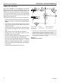
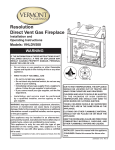
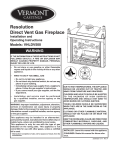
KHLDV Series
Direct Vent Gas Fireplace
Models:
KHLDV400, KHLDV500, KHLDV600
Installation and Operating Instructions
WARNING
If the information in these instructions is not
followed exactly, a fire or explosion may
result causing property damage, personal
injury or loss of life.
– Do not store or use gasoline or other flammable
vapors and liquids in the vicinity of this or any other
appliance.
–WHAT TO DO IF YOU SMELL GAS
• Do not try to light any appliance.
• Do not touch any electrical switch; do not use any
phone in your building.
• Immediately call your gas supplier from a neighbor's
phone. Follow the gas supplier's instructions.
• If you cannot reach your gas supplier, call the fire
department.
– Installation and service must be performed
by a qualified installer, service agency or the
gas supplier.
WARNING: Improper installation, adjustment, alteration,
services or maintenance can cause injury or property
damage. Refer to this manual. For assistance or additional
information consult a qualified installer, service agency
or the gas supplier.
This appliance may be installed in an aftermarket*,
permanently located, manufactured home (USA only) or
mobile home, where not prohibited by local codes.
This appliance is only for use with the type of gas
indicated on the rating plate. This appliance is not
convertible for use with other gases, unless a certified
kit is used.
*Aftermarket: Completion of sale, not for purpose of resale, from the
manufacturer.
730024
KHLDV cover
DUE TO HIGH TEMPERATURES, THE APPLIANCE
SHOULD BE LOCATED OUT OF TRAFFIC AND
AWAY FROM FURNITURE AND DRAPERIES.
CHILDREN AND ADULTS SHOULD BE ALERTED
TO T H E H A Z AR D S O F H I G H S UR FACE
TEMPERATURE AND SHOULD STAY AWAY TO
AVOID BURNS OR CLOTHING IGNITION.
YOUNG CHILDREN SHOULD BE SUPERVISED
WHEN THEY ARE IN THE SAME ROOM AS THE
APPLIANCE.
CLOTHING OR OTHER FLAMMABLE MATERIAL
SHOULD NOT BE PLACED ON OR NEAR THE
APPLIANCE.
Keep the room area clear and free from
combustible materials, gasoline, and
other flammable vapors and liquids.
INSTALLER: Leave this manual with the appliance.
CONSUMER: Retain this manual for future reference.
73D0024 3/13 Rev. 24
CONTENTS
KHLDV Series Gas Fireplace
Thank you and congratulations on your purchase of an Vermont Castings Group Fireplace.
PLEASE READ THE INSTALLATION AND OPERATION INSTRUCTIONS BEFORE USING THE APPLIANCE!
IMPORTANT: Read all instructions and warnings carefully before starting installation.
Failure to follow these instructions may result in a possible fire hazard and will void the warranty.
Important Safety Information..................................... 3
Check Gas Pressure - Signature Command........... 30
Code Approval............................................................. 4
Electrical Installation - Signature Command.......... 30
Electrical Wiring.................................................... 30
Junction Box Wiring.............................................. 31
Command Center Wall Installation........................ 31
Wall Switch Installation......................................... 31
Signature Command Wiring Diagram................... 32
Product Features......................................................... 5
High Elevations....................................................... 5
Gas Pressures........................................................ 5
Gas Specifications & Orifice Size........................... 5
Fireplace & Framing Dimensions.............................. 6
Pre-Installation Information........................................ 7
Before You Start...................................................... 7
Fireplace Framing................................................... 7
Fireplace Location................................................... 8
Clearances................................................................... 9
Secure Fireplace........................................................ 10
Finishing Material...................................................... 10
Venting Installation.....................................................11
Installation Precautions..........................................11
Installation Clearances...........................................11
Installation Planning.............................................. 12
Vertical Termination............................................... 12
Horizontal Termination.......................................... 12
How to Use a Vent Graph..................................... 14
Vertical Sidewall Installation.................................. 15
Vertical/Horizontal Termination Configurations..... 16
Below Grade Installation....................................... 17
Vertical Through-the-Roof Applications................. 18
Installation for Vertical Termination....................... 19
Fireplace Installation................................................. 21
Check Gas Type................................................... 21
Install Gas Piping ................................................. 21
Check Gas Pressure - Millivolt................................. 23
Electrical Installation - Millivolt................................ 23
Electrical Wiring.................................................... 23
Remote Wall Switch Installation - Millivolt.............. 24
Optional Fan/Blower Systems - Millivolt................. 24
Operating Instructions - Millivolt............................. 27
Lighting Pilot for the First Time............................. 27
Lighting Pilot......................................................... 28
Lighting Burner...................................................... 29
To Turn Off Gas..................................................... 29
Fan/Blower Systems - Signature Command........... 33
Operating Instructions Signature Command........................................... 34
Operating Instructions........................................... 35
To Turn Off Gas..................................................... 35
Signature Command System
Operation Instructions........................................... 36
Touch Screen Remote Control Operation............. 39
Glass Removal........................................................... 45
Final Installation........................................................ 46
Brick, Light Bulb and Lens Installation.................. 46
Rock Wool Placement........................................... 46
Log Placement 400/500 Series............................. 48
Log Placement 600 Series.................................... 50
Cleaning and Maintenance....................................... 53
Burner, Pilot and Control Compartment................ 53
Pilot Flame............................................................ 53
Burner Flame........................................................ 53
Venting System..................................................... 54
Glass Door............................................................ 54
Logs...................................................................... 54
Rock Wool . .......................................................... 54
Troubleshooting........................................................ 55
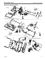
Replacement Parts.................................................... 58
Firebox Components............................................. 58
Standing Pilot Millivolt Control ............................. 59
Signature Command System................................ 61
Logs...................................................................... 63
Venting Components............................................. 64
Massachusetts Residents Only............................... 66
Warranty..................................................................... 67
Efficiencies................................................................ 68
73D0024
IMPORTANT SAFETY INFORMATION
KHLDV Series Gas Fireplace
OWNER
Please leave these instructions with the appliance.
Please retain these instructions for future reference.
WARNING
INSTALLER
• Read this owner’s manual carefully and completely before trying to assemble, operate,
•
•
or service this fireplace.
Any change to this fireplace or its controls can be dangerous.
Improper installation or use of this fireplace can cause serious injury or death from
fire, burns, explosions, electrical shock and carbon monoxide poisoning.
This fireplace is a vented product. This fireplace must be
properly installed by a qualified service person. The glass
door must be properly seated and sealed. If this unit is not
properly installed by a qualified service person with glass
door properly seated and sealed, combustion leakage can
occur.
CARBON MONOXIDE POISONING: Early signs of carbon
monoxide poisoning are similar to the flu with headaches,
dizziness and/or nausea. If you have these signs, the fireplace may not have been installed properly. Get fresh air
at once! Have the fireplace inspected and serviced by a
qualified service person. Some people are more affected
by carbon monoxide than others. These include pregnant
women, people with heart or lung disease or anemia,
those under the influence of alcohol, and those at high
altitudes.
Propane/LP gas and natural gas are both odorless. An
odor-making agent is added to each of these gases. The
odor helps you detect a gas leak. However, the odor added
to these gases can fade. Gas may be present even though
no odor exists.
Make certain you read and understand all warnings. Keep
this manual for reference. It is your guide to safe and proper
operation of this fireplace.
1. This appliance is only for use with the type of gas
indicated on the rating plate. This appliance is not
convertible for use with other gases unless a certified
kit is used.
2. For propane/LP fireplace, do not place propane/LP
supply tank(s) inside any structure. Locate propane/LP
supply tank(s) outdoors. To prevent performance problems, do not use propane/LP fuel tank of less than 100
lbs. capacity.
3. If you smell gas
• shut off gas supply.
• do not try to light any appliance.
• do not touch any electrical switch; do not use any
•
phone in your building .
immediately call your gas supplier from a neighbor’s
phone. Follow the gas supplier’s instructions.
73D0024
4. Never install the fireplace
• in a recreational vehicle
• where curtains, furniture, clothing, or other flam-
mable objects are less than 42" from the front, top,
or sides of the fireplace
• in high traffic areas
• in windy or drafty areas
5. This fireplace reaches high temperatures. Keep children
and adults away from hot surfaces to avoid burns or
clothing ignition. Fireplace will remain hot for a time after
shutdown. Allow surfaces to cool before touching.
6. Young children should be carefully supervised when
they are in the same room as the appliance. Toddlers,
young children and others may be susceptible to accidental contact burns. A physical barrier is recommended
if there are at risk individuals in the house. To restrict
access to a fireplace or stove, install an adjustable
safety gate to keep toddlers, young children and other
at risk individuals out of the room and away from hot
surfaces.
7. Do not modify fireplace under any circumstances. Any
parts removed for servicing must be replaced prior to
operating fireplace.
8. Turn fireplace off and let cool before servicing, installing, or repairing. Only a qualified service person should
install, service, or repair the fireplace. Have burner
system inspected annually by a qualified service
person.
9. You must keep control compartments, burners, and
circulating air passages clean. More frequent cleaning
may be needed due to excessive lint and dust. Turn off
the gas valve and pilot light before cleaning fireplace.
10. Have venting system inspected annually by a qualified
service person. If needed, have venting system cleaned
or repaired. Refer to Cleaning and Maintenance, Page
49.
11. Keep the area around your fireplace clear of combustible materials, gasoline, and other flammable vapor and
liquids. Do not run fireplace where these are used or
stored. Do not place items such as clothing or decorations on or around fireplace.
Continued on page 4
IMPORTANT SAFETY INFORMATION and CODE APPROVAL
12. Do not use this fireplace to cook food or burn paper or
other objects.
13. Never place anything on top of fireplace.
14. Do not use any solid fuels (wood, coal, paper, cardboard, etc.) in this fireplace. Use only the gas type
indicated on rating plate.
15. This appliance, when installed, must be electrically
grounded in accordance with local codes or in the
absence of local codes, with the National Electrical
Code, ANSI/NFPA 70, or the Canadian Electrical Code,
CSA C22.1.
16. Do not obstruct the flow of combustion and ventilation
air in any way. Provide adequate clearances around
air openings into the combustion chamber along with
adequate accessibility clearance for servicing and
proper operation.
17. When the appliance is installed directly on carpeting,
tile or other combustible material other than wood flooring, you must set appliance on a metal or wood panel
or hearth pad extending the full width and depth of the
appliance.
18. Do not use fireplace if any part has been exposed to
or has been under water. Immediately call a qualified
service technician to inspect the appliance and replace
any part of the control system and any gas control which
as been submerged in water.
19. Do not operate fireplace if any log is broken.
20. Do not use a blower insert, heat exchanger insert, or
any other accessory not approved for use with this
fireplace.
21. Do not operate the fireplace with glass door removed,
cracked, or broken.
IMPORTANT:
PLEASE READ THE FOLLOWING
CAREFULLY
It is normal for fireplaces fabricated of steel to give off
some expansion and/or contraction noises during the
start up or cool down cycle. Similar noises are found with
your furnace heat exchanger or car engine.
IMPORTANT:
PLEASE READ THE FOLLOWING
CAREFULLY
It is not unusual for gas fireplaces to give off some odor
the first time it is burned. This is due to the manufacturing
process.
Please ensure that your room is well ventilated
during burn off — open all windows.
It is recommended that you burn your fireplace for at
least ten (10) hours the first time you use it. Place the
fan switch in the “OFF” position during this time.
WARNING
KHLDV Series Gas Fireplace
Never connect unit to private (nonutility) gas wells. This gas is commonly
known as wellhead gas.
!
Code Approval
HOT GLASS WILL
CAUSE BURNS.
Direct Vent type appliances draw all combustion air from
outside of the dwelling through the vent pipe.
DO NOT TOUCH GLASS
UNTIL COOLED.
These appliances have been tested by CSA and found to
comply with the established standards for DIRECT VENT
GAS FIREPLACE HEATERS in the USA and Canada as
follows:
NEVER ALLOW CHILDREN
TO TOUCH GLASS.
LISTED VENTED GAS FIREPLACE HEATER
TESTED TO: ANSI Z21.88-2009 / CSA 2.33-2009
STANDARDS
A manufactured home (USA only) or mobile home OEM
installation must conform with the Manufactured Home
Construction and Safety Standard, Title 24 CFR, Part
3280, or when such a standard is not applicable, the
Standard for Manufactured Home Installations, ANSI/
NCSBCS A225.1, or Standard for Gas Equipped Recreational Vehicles and Mobile Housing, CSA Z240.4.
WARNING
!
AVERTISSEMENT
Un panneau vitré chaud peut causer des brûlures.
Laissez refroidir le panneau
vitré avant d’y toucher.
Ne laisser jamais les enfants
toucher le panneau vitré.
73D0024
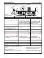
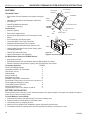
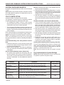
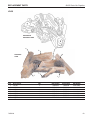
product features
KHLDV Series Gas Fireplace
• This appliance has been certified for use
•
•
•
•
•
•
with either natural or propane gas. See
appropriate data plates.
This appliance is not for use with solid
fuels.
The appliance is approved for bedroom or
bedsitting room installations.
The appliance must be installed in accordance with local codes if any. If none exist
use the current installation code. ANSI
Z223.1/NFPA 54 in the USA, CSA B149 in
Canada.
This appliance is mobile home approved.
The appliance must be properly connected
to a venting system.
The appliance is not approved for closet or
recessed installations.
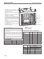
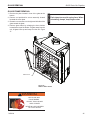
Access Panel
Blower Control
(optional)
Light Control
Off/Pilot/On Knob
Hi/Lo Knob
Ignitor
FP2124
Figure 1 KHLDV Series Fireplace
(shown with Millivolt)
HIGH ELEVATIONS
Input ratings are shown in BTU per hour and are certified
without deration for elevations up to 4,500 feet (1,370
m) above sea level.
For elevations above 4,500 feet (1,370 m) in USA,
installations must be in accordance with the current
ANSI Z223.1/NFPA 54 and/or local codes having jurisdiction.
In Canada, please consult provincial and/or local authorities having jurisdiction for installations at elevations
above 4,500 feet (1,370 m).
GAS pressures
Inlet Minimum
Inlet Maximum
Manifold Pressure
Natural Propane (LP)
4.5” w.c.
11.0” w.c.
10.5” w.c.
13.0” w.c.
3.5” w.c.
10.0” w.c.
FP2124
KHLDV
controls
Gas
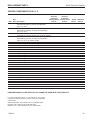
Specifications
& ORIFICE SIZE
Model
Fuel
KHLDV400NV
Nat.
KHLDV400PV
Lp
KHLDV400NTSC Nat.
KHLDV400PTSC
LP
KHLDV500NV
Nat.
KHLDV500PV
LP
KHLDV500NTSC Nat.
KHLDV500PTSC
LP
KHLDV600NTSC Nat.
KHLDV600PTSC
LP
73D0024
On/Off/RS Switch
Model
KHLDV400
KHLDV400
KHLDV500
KHLDV500
KHLDV600
KHLDV600
Max. Input
Btu/h
40,000
40,000
40,000
40,000
50,000
50,000
50,000
50,000
60,000
57,000
Min. Input
Btu/h
28,500
30,500
28,500
30,500
35,500
38,500
35,500
38,500
41,500
40,000
Orifice Size
Fuel
FrontRear
Nat. #49 (.073")
#35 (.110" )
LP #56 (.0465")
#52 (.0635")
Nat.
2.3 mm
#30 (.1285)
LP
#55 (.052")
#50 (.070")
Nat.
2.35 mm
#20 (.161")
LP
#54 (.055")
#49 (.073")
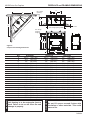
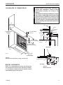
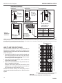
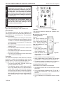
FIREPLACE and FRAMING DIMENSIONS
KHLDV Series Gas Fireplace
R
T
Min. Rough
Opening
Depth
D
E
J
Q H
R
S
1/2” or 5/8”
P - Min. Rough Opening Width
Min. Rough
Opening
Height
K
O
I
G
M F
Figure 2 Fireplace and Framing Dimensions
L
C
B
A
Unit framing is to be rectangular front to
back. Failure to do so will cause fire and
damage to property.
WARNING
WARNING
Ref.
KHLDV400
KHLDV500
A
44ZB\zn" (1141 mm)
48ZB\zn" (1243 mm)
B
35Z\x" (902 mm)
39Z\x" (1003 mm)
C
32"
(813 mm)
36"
(914 mm)
D
14Z\zn" (357 mm)
16Z\zn" (405 mm)
E
28Z\," (714 mm)
32Z\," (816 mm)
730129
F
30"
(762 mm)
30"
(762 mm)
DVKHL/KHLDV dims
G
38Z\zn" (967 mm)
38Z\zn" (967 mm)
H
23M\," (606 mm)
23M\," (606 mm)
I
44C\," (1127 mm)
44C\," (1127 mm)
J
8>\zn" (218 mm)
8>\zn" (218 mm)
K
4Z\v"
(108 mm)
4Z\v" (108 mm)
L
4"
(102 mm)
4"
(102 mm)
M
38M\zn" (976 mm)
38M\zn" (976 mm)
N
1"
(25 mm)
1"
(25 mm)
Framing Dimensions
O
44C\v" (1137 mm)
44C\v" (1137 mm)
P
45B\zn" (1153 mm)
49B\zn" (1253 mm)
Q
23M\," (606 mm)
23M\," (606 mm)
R
53B\," (1362 mm)
56M\zn" (1434 mm)
S
75M\," (1927 mm)
79M\," (2029 mm)
T
37ZB\zn" (964 mm)
39ZB\zn" (1014 mm)
N
KHLDV600
55"
(1397 mm)
45"
(1143 mm)
42"
(1067 mm)
19Z\zn" (484 mm)
38Z\," (968 mm)
36"
(914 mm)
44Z\zn" (1119 mm)
24Z\v" (616 mm)
50B\zn" (1278 mm)
8>\zn" (218 mm)
4Z\v" (108 mm)
4"
(102 mm)
44M\zn" (1129 mm)
1"
(25 mm)
50>\zn"
55Z\x"
24Z\x"
60C\v"
85ZB\zn"
43Z\v"
(1284 mm)
(1410 mm)
(622 mm)
(1543 mm)
(2183 mm)
(1099 mm)
Do not fill spaces around firebox with
insulation or other materials. This could
cause a fire.
73D0024
pRE-INSTALLATION INFORMATION
KHLDV Series Gas Fireplace
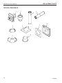
Before You Start
firebox framing
Read this homeowner manual thoroughly and follow all
instructions carefully. Inspect all contents for shipping
damage and immediately inform your dealer if any damage
is found. Do not install any unit with damaged, incomplete,
or substitute parts. Check your packing list to verify that
all listed parts have been received. You should have the
following:
Firebox framing can be built before or after the appliance
is set in place. Refer to Figure 2 for firebox dimensions
and framing. Construct firebox framing following Figure
2 for your specific installation requirements. The framing
headers may rest on the top of the firebox standoffs. Do
not bring headers below top of standoffs. NOTE: When
planning your framing and installation, keep in mind that
your gas line will come in on the right side of the box (as
you are facing it) and your electricity will come in on the
left side.
• Fireplace (Firebox and Burner System)
• Log Set
• Rock Wool
• Noncombustible Panel
ITEMS REQUIRED FOR INSTALLATION
• Phillips Screwdriver • Framing Materials
• Hammer
• Wall Finishing Materials
• Saw and/or saber saw • Level
• Measuring Tape
• Pliers
• Electric Drill and Bits • Square
• Pipe Wrench
• Tee Joint
• Noncombustible finishing material or dura-rock*
• Caulking Material (noncombustible)
• Fireplace Surround Material (noncombustible)
• Piping Complying with Local Codes
• Pipe Sealant Approved for use with Propane/LPG
The firebox may be installed directly on a combustible floor
or raised on a platform of an appropriate height. When
the firebox is installed directly on carpeting, tile, or other
combustible material, other than wood flooring, the firebox
shall be installed on a metal or wood panel extending the
full width and depth of the enclosure.
(Resistant to sulfur compounds)
* Only used if desired to cover painted face other than using tiles
or marble. If tiles or marble are used around the face then the
non-combustible material is not needed.
NOTE
COLD CLIMATE INSULATION
If you live in a cold climate, seal all cracks
around your appliance, and wherever cold air
could enter the room, with noncombustible
material. It is especially important to insulate
the outside chase cavity between the studs
and under the floor on which the appliance
rests, if the floor is above ground level.
NOTE: Refer to cold climate pilot information on Page 43
for more information on standing pilot vs. intermittent pilot
options.
73D0024
pRE-INSTALLATION INFORMATION
KHLDV Series Gas Fireplace
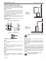
Fireplace Location
Plan for the installation of your appliance. This includes
determining where the unit is to be installed, the vent configuration to be used, framing and finishing details, and
whether any optional accessories (i.e. blower, wall switch,
or remote control) are desired. Consult your local building
code agency to ensure compliance with local codes, including permits and inspections.
Y
•
•
•
•
•
•
•
Minimum clearances to combustibles must be maintained.
This fireplace may be installed along a wall, across a
corner, or use an exterior chase. Refer to Figure 3 for
suggested locations.
Location should be out of high traffic areas and away
from furniture and draperies due to heat from appliance.
Never obstruct the front opening of the fireplace.
Do not install in the vicinity where gasoline or other
flammable liquids may be stored.
Vent pipe routing. Refer to the Venting section found in
this manual for allowable venting configurations.
These units can be installed in a bedroom. See National
Fuel Gas Code ANSI Z233.1/NFPA 54 — (current
edition), the Uniform Mechanical Code — (current edition), and Local Building Codes for specific installation
requirements.
These units can be installed in a bathroom.
A
B
C
The following factors should be taken into consideration:
• Clearance to side-wall, ceiling, woodwork, and windows.
E
Y
X
D
F
A Flat on Wall
B Cross Corner
Y 6" Minimum
C Island**
D Room Divider*
EFlat on Wall Corner*
F Chase Installation
** Island (C) and room divider (D) installation is possible as long as the
horizontal portion of vent system (X) does not exceed 20'. Refer to
Installing Horizontal Termination Configuration on Page 16.
* When you install your fireplace in (D) room divider or (E) flat on wall
corner positions (Y), a minimum of 6" clearance must be maintained
from perpendicular wall and front of fireplace.
Figure 3 Locating Gas Fireplace
73D0024
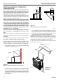
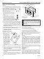
clearances
KHLDV Series Gas Fireplace
WARNING
Clearances to combustibles
12” (305 mm)
Max. Depth
Follow these instructions carefully to
ensure safe installation. Failure to follow
instructions exactly can create a fire
hazard.
The appliance cannot be installed on a carpet,
tile or other combustible material other than
wood flooring. If installed on carpet or vinyl
flooring, the appliance shall be installed on
a metal, wood or noncombustible material
panel extending full width and depth of the
appliance.
Wall
Stud
12" (305 mm)
72” (1829 mm)
Minimum Ceiling
21/2” Max Depth
(64 mm)
Insulation
Board
6" (152 mm)
16"
(406 mm)
Standoff
21/2" (64 mm)
12"
(305 mm)
10"
(254 mm)
16” (406 mm)
Min. From Opening
Top of Fireplace
Opening
10” (254 mm)
Min.From Opening
6”
(152 mm)
Min.
FP2128
He
Fir arth
ep M
lac inim
e O
u
pe m nin
g
Side View
FP2204
mantel clearances
Hearth 8” Min.
(203 mm)
Noncombustible
Figure 4 FP2128
Clearances from the
mantel, ceiling, and side wall.
mantel clearances
mantel clearances
NOTE: The combustible area above the facing must
not protrude more than 3/4" from the facing. If it does,
it is considered a mantel and must meet the mantel
requirements listed in this manual.
73D0024
FP2235
1"
FP2129
Fireplace Opening
2 /2"
3"
11/2"
1
Top View
5"
6"
31/2"
41/2"
45°
Figure 5 Mantel clearances
FP2129
mantel leg
SECURe FIREPLACE to floor or framing
KHLDV Series Gas Fireplace
The fireplace must be secured to the floor and/or to framing
studs as shown in Figure 6. Use two (2) wood screws or
masonry/ concrete screws to secure fireplace to the floor.
Use four (4) screws to attach fireplace to framing. The side
nailing flanges are 1/2" or 5/8" to accommodate different
wall thickness.
Framing Members
Noncombustible Material
6”
Noncombustible
Material Must Rise
at Least to Top of
Stand off
Secure to Floor Behind
Access Panels
Figure 6 Secure Fireplace to Floor and Framing Studs
FP2130
Nailing Flange
NOTE
All Combustible Materials
Must Keep 3/4" Spacing
Never install combustible materials
FP2130
over front face of fireplace.
secure fireplace to floor
Finishing Material
NOTE: Any remote wiring (i.e. remote control, wall switch,
and optional fan) must be done prior to final finishing to
avoid costly reconstruction.
10
Only noncombustible materials (i.e. brick, tile, slate, steel,
or other materials with a UL fire rating of Zero) may be
used to cover the black painted face of the appliance. It is
permissible to bring combustible wall board to the top of
the stand-offs on the top and the sides of the unit. A 300°F
minimum adhesive may be used to attach facing materials to the black surface. If joints between the finished wall
and the fireplace surround are sealed, a 300°F minimum
sealant material (General Electric RTV103 or equivalent)
must be used.
73D0024
WARNING
venting INSTALLATION
KHLDV Series Gas Fireplace
Read all instructions completely and
thoroughly before attempting installation.
Failure to do so could result in serious injury,
property damage or loss of life. Operation
of improperly installed and maintained
venting system could result in serious injury,
property damage or loss of life.
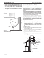
CL
of pipe
*3”
**1”
**1”
INSTALLATION PRECAUTIONS
400/500 - 73”
(1854 mm)
Consult local building codes before beginning the
installation. The installer must make sure to select the
proper vent system for installation. Before installing vent
kit, the installer must read this fireplace manual and vent
kit instructions.
24" Vertical Rise
Required Before
Horizontal Run
600 - 79”
(2007 mm)
Only a qualified installer/service person should install venting system. The installer must follow these safety rules:
• Wear gloves and safety glasses for protection.
• Use extreme caution when using ladders or when on
rooftops.
• Be aware of electrical wiring locations in walls and ceilings.
The following actions will void the warranty on your venting system:
NOTICE
Failure to follow these instructions will void
the warranty.
WARNING
approved by Vermont Castings Group.
• Installation other than permitted by these instructions.
This fireplace must be vented to the outside.
The venting system must NEVER be attached
to a chimney serving a separate solid fuel
burning appliance. Each gas appliance must
use a separate vent system. Do not use
common vent systems.
FP2131
Figure 7 Combustible Clearances for Vent Pipe
FP2131
pipe clearances
* A minimum ofVent
3" clearance
to the top is required along horizontal length
until flue pipe penetrates outside wall.
** A minimum 1" clearance to combustibles permitted all around flue at
outside wall
WARNING
• Installation of any damaged venting component.
• Unauthorized modification of the venting system.
• Installation of any component part not manufactured or
Horizontal sections of this vent system
require a minimum of 3" clearances to
combustibles at the top of the flue and 1"
clearance at the sides and bottom until the
flue penetrates the outside wall. A minimum
1" clearance all around the flue is acceptable
at this point of penetration. Unless the
vertical run is 7Z\x' or higher from floor of
fireplace, the clearance for horizontal run
is 1" on all sides.
Vertical sections of this vent system require
a minimum of 2" clearance to combustibles
at the top of the unit directly above the
stand-off. A minimum of 1" clearance all
around the flue is acceptable thereafter.
73D0024
11
VentING installation
KHLDV Series Gas Fireplace
• Horizontal Termination
• Vertical Termination
It is important to select the proper length of vent pipe for
the type of termination you choose. It is also important to
note the wall thickness.
for horizontal termination
Select the amount of vertical rise desired. All horizontal run
of venting must have 1/4" rise for every 12" of run towards
the termination below 7Z\x" of vertical rise from floor of fireplace. With 7Z\x feet or more of vertical rise from the floor
of the fireplace, the horizontal run may be level. NEVER
run vent piping down.
You may use up to three 90° elbows in this vent configuration. Refer to Vertical/Horizontal Termination Configurations
on Page 16.
Horizontal venting which incorporates the twist lock pipe
must be installed on a level plane without an inclining or
declining slope.
For vertical termination
Measure the distance from the fireplace floor to the ceiling. Add the ceiling thickness, the vertical rise in an attic
or second story, and allow for sufficient vent height above
the roof line.
NOTICE
Treatment of firestops and construction of
the chase may vary from building type to
building type. These instructions are not
substitutes for the requirements of local
building codes. You must follow all local
building codes.
NOTICE
NOTE: You may use two 45° elbows in place of a 90° elbow.
You must follow rise to run ratios when using 45° elbows.
The appliance is approved for use with three 90° elbows
maximum or a combination of 90° and 45° elbows up to
a maximum of 270°.
When installing in a chase, you should
insulate the chase as you would the outside
walls of your home. This is especially
important in cold climates. Insulation
should be considered a combustible
material. Maintain proper clearances to all
combustible materials.
12
Never run the vent pipe down. This may
cause excessive temperatures which could
cause a fire.
For two-story applications, firestops are required at each
floor level. If an offset is needed in the attic, additional pipe
and elbows will be required.
You may use a chase with a vent termination with exposed
pipe on the exterior of the house. See Installing A Vent
System in an Outside Chase below. If pipe is enclosed in
chase, it is not exposed.
It is very important that the venting system maintain its balance between the combustion air intake and the flue gas
exhaust. Certain limitations apply to vent configurations
and must be strictly followed.
Installing a vent system in an
outside chase
A chase is a vertical boxlike structure built to enclose
venting that runs along the outside of a building. A chase
is required for such venting.
WARNING
There are two basic types of direct-vent installation:
WARNING
installation planning
Always maintain minimum clearances around
vent systems. The minimum clearances to
combustibles for horizontal vent pipe are 3"
at the top* and 1" at the sides and bottom
of the vent system until the pipe penetrates
the nearest vertical wall (1" required). A 1"
minimum clearance all around the pipe must
be maintained at outside wall and on vertical
runs. Do not pack the open air spaces with
insulation or other materials. This could
cause high temperatures and may present
a fire hazard.
*Unless the vertical run is 7Z\x feet or higher
from floor of fireplace, the clearance for the
horizontal run is 1" on all sides.
73D0024
VENTING INSTALLATION
KHLDV Series Gas Fireplace
General Venting Information - Termination Location
INSIDE
CORNER DETAIL
V
G
H
A
D
L
V
E
C
B
V
F
Figure 8 Termination Locations
B
Fixed
Closed
Ope
ra
V
B
B
V
B
V VENT TERMINATION
V
J
A
CFM145a
V
Fixed
Closed
Operable
ble
X AIR SUPPLY INLET
X
B
M
I
V
K
X
AREA WHERE TERMINAL IS NOT PERMITTED
Canadian Installations1US Installations2
CFM145a
DV Termin Location
A = Clearance above grade, veranda, porch, 12” (30 cm)
12” (30 cm)
5/01/01 Rev. 12/05/01
deck, or balcony
sta
B = Clearance to window or door that may be 6” (15 cm) for appliances 6” (15 cm) for appliances
opened
< 10,000BTU/h (3kW), 12” (30 cm) < 10,000 BTU/h (3kW), 9”
for appliances > 10,000 Btuh (3kW) and (23 cm) for appliances > 10,000
< 100,000 BTU/h (30kW), 36” (91 cm)
Btuh (3kW) and < 50,000 BTU/h
for appliances > 100,000 BTU/h (30kW) (15kW), 12” (30 cm) for
appliances > 50,000 BTU/h(15kW)
C = Clearance to permanently closed window
12” (305 mm) recommended to
12” (305 mm) recommended to prevent window condensation
prevent window condensation
D = Vertical clearance to ventilated soffit located
above the terminal within a horizontal 18” (458 mm)
18” (458 mm)
distance of 2’ (610mm) from the center
line of the terminal
E = Clearance to unventilated soffit
12” (305 mm); 12" (305 mm);
Clearance to vinyl soffit (30" (762 mm)
Clearance to vinyl soffit (30" (762 mm)
F = Clearance to outside corner see next page
see next page
G =Clearance to inside corner (see next page) see next page
see next page
H = Clearance to each inside of center line
3’ (91 cm) within a height of 15’ (5 m) 3’ (91 cm) within a height of 15’
extended above meter/regulator assembly
above the meter/regulator assembly
(5 m) above the meter/regulator assy
I = Clearance to service regulator vent outlet
3’ (91 cm)
3’ (91 cm)
J = Clearance to nonmechanical air supply inlet 6” (15 cm) for appliances < 10,000
6” (15 cm) for appliances
to building or the combustion air inlet to any BTU/h (3kW), 12” (30 cm) for
< 10,000 BTU/h (3kW), 9”
other appliances
appliances > 10,000 BTU/h (3kW) and (23 cm) for appliances > 10,000
< 100,000 Btuh (30kW), 36” (91 cm)
BTU/h (3kW) and < 50,000 BTU/h
for appliances > 100,000 BTU/h (30kW) (15kW), 12” (30 cm) for appliances > 50,000 BTU/h(15kW)
K = Clearance to a mechanical air supply inlet
6’ (1.83 m)
3’ (91 cm) above if within 10'
(3 m) horizontally
L = Clearance above paved sidewalk or paved 7’ (2.13 m)†
7’ (2.13 m)†
driveway located on public property
M =Clearance under veranda, porch, deck or
12” (30 cm)
12” (30cm)
balcony
1 In accordance with the current CSA-B149 Installation Codes
2 In accordance with the current ANSI Z223.1/NFPA 54 National Fuel
Gas Codes
† A vent shall not terminate directly above a sidewalk or paved
driveway which is located between two single family dwellings and serves both dwellings
only permitted if veranda, porch, deck or balcony is fully open on a
minimum 2 sides beneath the floor:
73D0024
NOTE: 1. Local codes or regulations may require different clearances.
2. The special venting system used on Direct Vent Fireplaces are certified as part of the appliance, with clearances tested and approved by the listing agency.
3. Vermont Castings Group assumes no responsibility for the
improper performance of the appliance when the venting system does not meet these requirements.
13
VENTING INSTALLATION
KHLDV Series Gas Fireplace
Termination Clearances
Termination clearances for buildings with combustible and noncombustible exteriors.
Alcove Applications*
Inside Corner
Outside Corner
G=
Combustible
6" (152 mm)
G
V
F=
Combustible
6" (152 mm)
Noncombustible
2" (51 mm)
V
Noncombustible
2" (51 mm)
C
V
O
F
Balcony with perpendicular side wall
Balcony with no side wall
D
C
E
E = Min. 2” (51 mm) for
non-vinyl sidewalls
Min. 12” (305 mm) for
vinyl sidewalls
O = 8’ (2.4 m) Min.
M
V
Figure 9 Termination
Clearances
M
V
P
M=
Combustible &
Noncombustible
12" (305 mm)
Combustible &
Noncombustible
M = 12" (305 mm)
P = 6” (152 mm)
No.
of Caps DMin. CMax.
1
3’ (914 mm) 2 x DActual
2
6’ (1.8 m)
1 x DActual
3
9’ (2.7 m)
2/3 x DActual
4
12’ (3.7 m) 1/2 x DActual
DMin. = # of Termination caps x 3
CMax. = (2 / # termination caps) x DActual
584-15
*NOTE: Termination in an alcove space (spaces open only on one side and with an overhang) is permitted with the dimensions specified for vinyl or
non-vinyl siding and soffits. 1. There must be a 3’ (914 mm) minimum between termination caps. 2. All mechanical air intakes within 10’ (1 m) of a
termination cap must be a minimum of 3’ (914 mm) below the termination cap. 3. All gravity air intakes within 3’ (914 mm) of a termination cap must
be a minimum of 1’ (305 mm) below the termination cap.
The Vent Graph should be read in conjunction with the
following vent installation instructions to determine the
relationship between the vertical and horizontal dimensions
of the vent system.
1. Determine the height of the center of the horizontal vent
pipe exiting through the outer wall. Using this dimension on the Sidewall Vent Graph below, locate the point
intersecting with the slanted graph line.
2. From the point of this intersection, draw a vertical line
to the bottom of the graph.
3. Select the indicated dimension, and position the fireplace in accordance with same.
Example: If the vertical dimension from the floor of the
fireplace is 11' (3.4 m) the horizontal run to the face of
the outer wall must not exceed 16' (4.9 m).
Sidewall Vent Graph showing the relationship between
vertical and horizontal dimensions for a Direct Vent flue
system.
eg: A
2 4 6 8 10 12 14 16 18 20
Horizontal dimension from the finished outside wall
to the center of the pipe on the fireplace
Figure 10 Rear Wall Venting Graph (No Horizontal Elbows)
14
Vertical Dimension From the Floor of Unit to the Center of the
Horizontal Vent Pipe
How To Use The Vent Graph
40
38
36
34
32
30
28
26
24
22
20
18
16
14
12
10
8
6
4
2
Dimensions in
Feet
FP2132
sidewall vent graph 73D0024
ventING installation
KHLDV Series Gas Fireplace
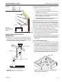
Vertical Sidewall Installation NOTE: Sealant is not required to assemble fireplace
venting. Do not use silicone sealant at the inner flue
exhaust connections.
Step 1
Locate vent opening on the wall. It may be necessary to
first position the fireplace and measure to obtain hole location. Depending on whether the wall is combustible or
noncombustible, cut opening to size. Figure 11 (For combustible walls first frame in opening.)
Combustible Walls: Cut a 10Z\x”H x 10Z\x”W (267 x 267
mm) hole through the exterior wall and frame as shown.
Figure 11
Noncombustible Walls: Hole opening must be 8Z\x” (216
mm) in diameter.
X
X
Figure 12 Vertical Height
Requirement
FP1181
X
Vent Opening for Combustible Walls
10Z\x”
(267 mm) Min.
10Z\x”
(267 mm)
Min.
Fireplace Hearth
Framing Detail
Opening for Noncombustible Wall
FP1182
Always install horizontal venting on a level
plane.
8Z\x”
(216 mm)
Fireplace Hearth
Figure 11 Locate vent opening on wall
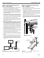
Step 2
FP2293
Secure firestop to the inside frame, center in the
10Z\x" vent opening.
10Z\x"
Step 6
x
VO584-100
Vent Opening
Step 3
djtMeasure the vertical height
Place fireplace into 2/99
position.
(X) required from the base of the flue collars to the center
of the wall opening. Figure 12
Step 4
Using appropriate length of pipe section(s) attach to fireplace with three (3) screws. Follow with the installation of
the elbow.
Step 5
Measure the horizontal length requirement figuring a 1Z\v”
(32 mm) overlap, i.e. from the elbow to the outside wall
cap. Figure 13
73D0024
X
Figure 13 Horizontal Length
Requirement
Use appropriate length of pipe sections - telescopic or
fixed - and install.
Sealing vent pipe and firestop gaps with high temperature sealant will restrict cold air being drawn in
around fireplace.
Step 7
Guide the vent terminations 5” and 8” collard into their
respective vent pipes. Double check that the vent pipes
overlap the collars by a minimum of 1Z\v" (32 mm). Secure
the termination to the wall with screws provided and caulk
around the wall plate to weatherproof. As an alternative to
screwing the termination directly to the wall, you may also
use expanding plugs or an approved exterior construction
adhesive.
Support horizontal pipes every 36” (914
mm) with metal pipe straps.
15
VENTING INSTALLATION
KHLDV Series Gas Fireplace
VERTICAL/Horizontal termination
configurations
36"
(914 mm)
Max.
36"
(914 mm)
Max.
Since it is very important that the venting system maintain its balance between the combustion air intake and
the flue gas exhaust, certain limitations as to vent configurations apply and must be strictly adhered to.
The Vent Graph, showing the relationship between vertical
and horizontal side wall venting, will help to determine the
various dimensions allowable. Figure 10
NOTE: Horizontal sections of this vent system require
a minimum of 3" clearances to combustibles at the top
of the flue and 1" clearance at the sides and bottom
until the flue penetrates the outside wall. A minimum
1" clearance all around the flue is acceptable at this
point of penetration. Unless the vertical run is 7Z\x feet
or higher from floor of fireplace, the clearance for the
horizontal run is 1" on all sides.
Vertical sections of this vent system require a minimum
of 1" clearance to combustibles on all sides of the
pipe.
When vent exits through foundations less than 20" below
outcrop, the termination must be flush up with outcropped
wall above.
It is best to locate the fireplace in such a way that minimizes
the number of offsets and horizontal vent length.
The horizontal vent run refers to the total length of vent
pipe from the flue collar of the fireplace (or the top of the
Transition Elbow) to the face of the finished outside wall.
Figure 15 Maximum Horizontal Run with No Rise
FP1177
• If a 90° elbow is used in the horizontal vent run (level
height maintained) the horizontal vent length is reduced
by 36". Figure 16. This does not apply if the 90° elbows
are used to increase or redirect a vertical rise.
Example: According to the vent graph (Page 14) the maxiMax 20"
mum horizontal vent length in a system with a 10' vertical
rise is 17Z\x’ (5.3 m) and if a 90° elbow is required in the
horizontal vent it must be reduced to 14Z\x' (4.4 m).
In Figures 16 and 17 dimension A plus B must not be
greater than 14Z\x' (4.4 m).
90° Elbow = 36" (914 mm)
Reduction
• The maximum number of 90° elbows per side wall
installation is three (3). Figure 14
A
B
Max 20"
3 x 90°
Elbows
24" Min.
10’
FP1176
Figure 14 Maximum Three (3) 90° Elbows Per Installation
• A minimum of 24" is required before a 90° elbow. If a 90°
FP2133
FP1177
Figure 16 max horizontal
run Run
Horizontal
Reduction
elbow is fitted directly after 24" vertical section mounted
to the top of the fireplace, the maximum horizontal vent
run before the termination or a vertical rise is 36” (914
mm). Figure 15
16
FP1176
FP2133
Horizontal run
reduction
73D0024
ventING installation
KHLDV Series Gas Fireplace
• For each 45° elbow installed in the horizontal run, the
length of the horizontal run MUST be reduced by 18" (45
cm). This does not apply if the 45° elbows are installed
on the vertical part of the vent system.
• The maximum number of elbow degrees in a system is
270°. Figure 17
Example:
Elbow 1 = Elbow 2 = Elbow 3 = Elbow 4 = Total Angular Variation = When it is not possible to meet the required vent terminal
clearances of 12" above grade level, a snorkel kit is recommended. It allows installation depth down to 7" (178 mm)
below grade level. The 7" (178 mm) is measured from the
center of the horizontal vent pipe as it penetrates through
the wall.
Ensure that sidewall venting clearances are observed.
If venting system is installed below ground, we recommend a window well with adequate and proper drainage
to be installed around the termination area.
90°
45°
45°
90°
270°
1
1
2
2
3
3
4
4
24"
Minimum
Figure 17 Maximum Elbow Usage
Below Grade Installations
FP1180
If installing a snorkel, a minimum 24" vertical rise is necessary. The maximum horizontal run with the 24” vertical pipe
is 36". This measurement is taken from the collar of the
fireplace (or transition elbow) to the face of the exterior wall.
See the Sidewall Venting Graph for extended horizontal
run if the vertical exceeds 24".
1. Establish vent hole through the wall.
2. Remove soil to a depth of approximately 16" below base
of snorkel. Install drain pipe. Install window well (not
supplied). Refill hole with 12" of coarse gravel leaving
a clearance of approximately 4" below snorkel. Figure
18
3. Install vent system.
4. Ensure a watertight seal is made around the vent pipe
coming through the wall.
5. Apply high temperature sealant caulking (supplied)
around the 5" and 8" snorkel collars.
6. Slide the snorkel into the vent pipes and secure to the
wall.
7. Level the soil so as to maintain a 4" clearance below
snorkel. Figure 18
Screws
Firestop
Minimum
4" Clearance
Ground
Window
Well
24"
Minimum
Gravel
Drain
Foundation Wall
FP2134
73D0024
Figure 18 Below Grade Installation
FP2134
below grade install
17
ventNG installation
KHLDV Series Gas Fireplace
If the foundation
is recessed, use
recess brackets
Snorkel
(not supplied)
for securing
Foundation
lower portion Recess
of the snorkel.
Wall
Fasten brackScrews
ets to wall first,
then secure to
Sheet
s n o r k e l w i t h Watertight Seal
Metal
self drilling #8 x Around Pipe
Screws
1/2 sheet metal
screws. It will
be necessary Figure 19 to extend vent Snorkel Installation, Recessed Foundation
pipes out as far
FP1966
as the protruding wall face. Figure
Restrictor
Disc
Figure 20 Install Restrictor Disc into
Fireplace Collar
Fireplace
Collar
FP2703
WARNING
snorkel
• Do not back fill around snorkel.
•A clearance of at least 4" must be
maintained between the snorkel and the
soil.
NOTICE
vertical through-the-roof
applications
A restrictor disc must be installed on
vertical terminations that are higher than
12' (366 cm).
Install restrictor disc as shown in Figure 20 for vertically
vented applications.
Up to two (2) restrictor discs may be needed for 40' installation.
The two (2) restrictor discs suppled will work for most installations. If a third disc is needed order Part No. 56D3027.
This gas fireplace has been approved for,
• Vertical installations up to 40' (12 m) in height. Up to
a 10' (3 m) horizontal vent run can be installed within
the vent system using a maximum of two 90° elbows.
Figure 21
NOTE: Horizontal sections of this vent system require a
minimum of 3" clearances to combustibles at the top of
the flue and 1" clearance at the sides and bottom until the
flue penetrates the outside wall. A minimum 1" clearance
all around the flue is acceptable at this point of penetration.
Unless the vertical run is 7Z\x feet or higher form floor of
fireplace, the clearance for the horizontal run is 1" on all
sides.
40' Maximum Height
12' Minimum Height
10'
Maximum
24" Min.
FP2703
restrictorSupport
disc Straps
Every 3'
FP1183
Figure 21 Support Straps for Horizontal Runs
Vertical sections of this vent system require a minimum of
1" clearance to combustibles on all sides of the pipe.
• Up to two 45° elbows may be used within the horizontal
run. For each 45° elbow used on the horizontal plane,
the maximum horizontal length must be reduced by 18"
(450 mm).
Example: Maximum horizontal length
No elbows = 10’ (3 m)
1x45° elbows = 8.5’ (2.6 m)
2x45° elbows = 7’ (2.1 m)
• A minimum of an 8' (2.5 m) vertical rise is required.
• Two sets of 45°elbows offsets may be used within the
vertical sections. From 0 to a maximum of 8' (2.5 m)
of vent pipe can be used between elbows. Figure 22
• The maximum angular variation allowed in the system
is 270°. Figure 22
• For the minimum height of the vent above the highest
point of penetration through the roof refer to Page 20,
Figure 26.
18
73D0024
FP1183
max height
VENTING INSTALLATION
Example:
Elbow 1 Elbow 2 Elbow 3 Elbow 4 Total Angular Variation =
=
=
=
=
KHLDV Series Gas Fireplace
90°
45°
45°
90°
270°
For optimal flame appearance, a restrictor disk is necessary
on straight vertical runs of 10' of more.
• Runs may not incorporate elbows.
• The disk is part number 56D3027 and is included in
installation manual packet.
• Drop the disk into a 5" inner collar before installing
1 the first section of flue or install at the last section
before installing the termination.
•2 An additional disk may be installed on runs of 35' or more.
Rotate disks perpendicular to each other.
1
2
3
3
NOTE: Pay special attention to these installation instructions
for required clearances (air space) to combustibles when
4
passing through ceilings, walls, roofs, enclosures, attic
rafters, etc. Do not pack air spaces with insulation. Also
note maximum vertical rise of the venting system and any
maximum horizontal offset limitations. Offsets must fall
within the parameters shown in Figures 22 and 23.
4
24" Min.
Figure 22 Maximum Elbow
Usage
FP1179
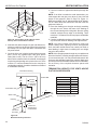
installation for vertical
termination
1. Determine the route your vertical venting will take. If
ceiling joist, roof rafters or other framing will obstruct
the venting system, consider an offset. Refer to Figure
23 to avoid cutting load bearing members. FP1179
2. Set fireplace in desired location. Drop a line plumb down
from the ceiling to the position of the flue exit. Mark the
center point where the vent will penetrate the ceiling.
Drill a small locating hole a this point.
Drop a plumb line from the inside of the roof to the ceiling
locating hole in the ceiling. Mark the center point where
the vent will penetrate the roof. Drill a small locating hole
at this point.
flat ceiling installation
1. Cut a 101/2" (241 mm) square hole in the ceiling using
max bends the locating hole as a center point The opening should
be framed to 101/2"x101/2" (241 x 241 mm) inside dimensions as shown in Figure 25 using framing lumber the
Roof Flashing
same size as the ceiling joist. If the area above the ceiling is an insulated ceiling or a room, nail firestop from
the top side. This prevents loose insulation from falling
into the required clearance space. Figure 24. Otherwise,
install firestop below the framed hole. Figure 25
Wall Strap
Nails
45° Elbows
FP1669
Ceiling Firstop
Figure 23 Offset with Wall Strap and 45° Elbows
Firestop
Figure 24 - If Area Above is a Room, Install Firestop
above Framed Hole as Shown
FP1969
offset w/ wallstrap
73D0024
FP1969
firestop w room above
19
VENTING INSTALLATION
KHLDV Series Gas Fireplace
/"
10
1 2
101
4. Connect a section of pipe and extend up through the
hole.
NOTE: If an offset is needed to avoid obstructions, you
must support the vent pipe every three (3) feet. Use wall
straps for this purpose. Refer to Page 18, Figure 21.
Whenever possible, use 45° elbows instead of 90° elbows.
The 45° elbow offers less restriction to the flow of the flue
gases and intake air.
5. Place the flashing over the pipe section(s) extending
through the roof. Secure the base of the flashing to
the roof and framing with roofing nails. Be sure roofing
material overlaps the top edge of the flashing. There
must be a 1" clearance from the vent pipe to combustible
materials.
6. Continue to add pipe sections until the height of the vent
cap meets the minimum building code requirements.
NOTE: You must increase vent height for steep roof
pitches. Nearby trees, adjoining roof lines, steep pitched
roofs, and other similar factors may cause poor draft or
down-drafting in high winds. Increasing the vent height
may solve this problem.
NOTE: If the vent pipe passes through any occupied areas
above the first floor, including storage spaces and closets,
you must enclose pipe. You may frame and sheetrock the
enclosure with standard construction material. Make sure
to meet the minimum allowable clearances to combustibles.
Do not fill any of the required clearance spaces with
insulation. /2"
FP1970
Firestop
Nails
Figure 25 - If Area Above is Not a Room, Install
Firestop above Framed Hole as Shown
2. Assemble the desired lengths of pipe and elbows necessary to reach from the burner system flue up through
FP1970
the firestop. Be sure
pipe and elbow connections are
fully twist-locked. firestop no room
3. Cut a hole in the roof using the locating hole as a center
point. (Cover any exposed open vent pipes before
cutting hole in roof). The 101/2"x101/2" (267 x 267 mm)
hole must be measured on the horizontal. Actual length
may be larger depending on the pitch of the roof. There
must be a 1" minimum clearance from the vent pipe to
combustible materials. (Insulation should be considered
a combustible material).
TERMINATION HEIGHTS FOR VENTS ABOVE
FLAT OR SLOPED ROOFS
Horizontal Overhang
2 ft. Min.
Vertical Wall
2 ft. Min.
Lowest
Discharge
Opening
Termination Vent
H*
12
X
Storm Collar
FP1971
Roof Pitch
Flat to 6/12
Over 6/12 to 7/12
Over 7/12 to 8/12
Over 8/12 to 9/12
Over 9/12 to 10/12
Over 10/12 to 11/12
Over 11/12 to 12/12
H (feet)
1.0
1.25
1.5
2.0
2.5
3.25
4.0
*H - Minimum height from roof to
lowest discharge opening of vent
Flashing
Concentric
Vent Pipe
1" Minimum
Clearances to
Combustibles
Figure 26 Minimum Chimney Clearance
20
FP1971
Min chimney clearance
73D0024
fireplace installation
KHLDV Series Gas Fireplace
check gas type
Use proper gas type for the fireplace you are installing.
If you have conflicting gas type, do not install fireplace.
See dealer where you purchased the fireplace for proper
fireplace for your gas type or conversion kit.
External
Regulator
100 gallon (min)
Propane/LP
Supply Tank
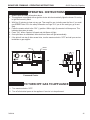
WARNING
Installing gas piping to fireplace /
burner system location
A qualified installer or service person
must connect appliance to gas supply.
Follow all local codes.
Vent Pointing
Down
installation items needed
Before installing fireplace and burner system, make sure
you have the items listed below.
Test gauge connection*
• Tee joint Equipment shutoff valve*
• Pipe wrench
Sediment trap (recommended)
External regulator (supplied by installer)
Piping (check local codes)
Sealant (resistant to propane/LP gas)
Approved flexible gas line with gas connector (if
allowed by local codes — not provided)
* A CSA design-certified equipment shutoff valve with 1/8"
NPT tap is an acceptable alternative to test gauge connection. Purchase the CSA design-certified equipment shutoff
valve from your dealer.
CAUTION
For propane/LP connections only, the installer must supply
an external regulator. The external regulator will reduce
incoming gas pressure. You must reduce incoming gas
pressure to between 11 and 13 inches of water. If you do
not reduce incoming gas pressure, burner system regulator damage could occur. Install external regulator with the
vent pointing down as shown in Figure 27. Pointing the
vent down protects it from freezing rain or sleet.
Figure 27 External Regulator with Vent Pointing Down
(Propane/LP Only)
FP1977
external regulator
CAUTION
•
•
•
•
•
•
•
FP1977
Use only new black iron or steel pipe.
Internally tinned copper or copper tubing
can be used per National Fuel Code, section
2.6.3, providing gas meets hydrogen sulfide
limits, and where permitted by local codes.
Gas piping system must be sized to provide
minimum inlet pressure (listed on data plate)
at the maximum flow rate (BTU/hr). Undue
pressure loss will occur if the pipe is too
small.
When using copper of flex connectors use only fittings
approved for gas connections. The gas control inlet is
3/8" NPT.
For propane/LP units, never connect
fireplace directly to the propane/LP supply.
This burner system requires an external
regulator (not supplied). Install the external
regulator between the burner system and
propane/LP supply.
73D0024
21
fireplace installation
CAUTION
Only persons licensed to work with gas
piping may make the necessary gas
connections to this appliance.
NOTE: The gas line connection may be made using 1/2"
rigid tubing or an approved flex connector. Since some
municipalities have additional local codes it is always best
to consult your local authorities and the current edition of
the National Fuel Gas Code ANSI.Z223.1, NFPA54. In
Canada CSA-B149 (1 or 2) Installation Code.
A listed manual shutoff valve must be installed upstream of
the appliance. Union tee and plugged 1/8" NPT pressure
tapping point should be installed upstream of the appliance. Figure 28
IMPORTANT: Install main gas valve (equipment shutoff
valve) in an accessible location. The main gas valve is for
turning on or shutting off the gas to the fireplace.
Check your building codes for any special requirements for
locating equipment shutoff valve to fireplaces.
A manual shutoff valve must be installed
upstream of the appliance. Union tee
and plugged 1/8" NPT pressure tapping
point should be installed upstream of the
appliance. Figure 28
We recommend that you install a sediment trap/drip leg in
supply line as shown in Figure 28. Locate sediment trap/
drip leg where it is within reach for cleaning. Install in piping
system between fuel supply and burner system. Locate
sediment trap/drip leg where trapped matter is not likely
to freeze. A sediment trap collects moisture and contaminants and keeps them from going into the burner system
gas controls. If sediment trap/drip leg is not installed or is
installed wrong, burner system may not run properly.
CAUTION
WARNING
KHLDV Series Gas Fireplace
Use pipe joint sealant that is resistant to
liquid petroleum (LP) gas.
Apply pipe joint sealant lightly to male threads. This will
prevent excess sealant from going into pipe. Excess sealant in pipe could result in clogged burner system valves.
CSA Design-Certified Equipment Shutoff Valve
with 1/8" NPT Tap*
Approved Flexible
Gas Line
Tee Joint
Sediment Trap/Drip Leg
Figure 28 Gas Connection
Pipe Nipple
Cap
FP1978
gas connection
22
3"
M
ini
mu
m
Natural Gas
From Gas Meter
(4.5" w.c. to 10.5" w.c. Pressure)
Propane/LP
From External Regulator
(11" w.c. to 13" w.c. Pressure)
73D0024
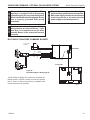
MILLIVOLT - CHECK GAS PRESSURE and Electrical installation
KHLDV Series Gas Fireplace
WARNING
1. Check gas type. The gas supply must be the same as
stated on the appliance’s rating decal. If the gas supply
is different from the fireplace, STOP! Do not install the
appliance. Contact your dealer immediately.
2. To ease installation, a 24" (610 mm) flex line with manual
shut-off valve has been provided with on this appliance.
Install and attach 3/8" gas line onto shut-off valve.
3. After completing gas line connection, purge air from
gas line and test all gas joints from the gas meter to the
fireplace for leaks. Use a solution of 50/50 water and Pressure
Test “IN”
soap solution or a gas sniffer.
4. To adjust flame height, turn HI/LO knob to HI to get Pressure
maximum pressure to burner. Turn HI/LO knob to LO Test “OUT”
FP1979
to get minimum pressure. Note: To make the process
of checking the gas pressure easier, unfasten the two HI/LO Knob
screws which secure the gas valve to the side of the
Pilot Adjustment
firebox and bring forward. [Remove the glass to allow
Screw
the valve to come forward. (Refer to Page 45 for glass
Figure 29 removal.)] When done, you must refasten the gas valve
Gas Pressure Check at Gas Valve
into place.
FP1979
5. To check gas pressures at valve, turn captured screw
Millivolt gas valve
counter clockwise 2 or 3 turns and then place tubing
to pressure gauge over test point. Turn unit to high.
Do not use open flame to check
Figure 29. After taking pressure reading, be sure and
for gas leaks.
turn captured screw clockwise firmly to reseal. Do not
over torque. Check test points for gas leaks.
Electrical Wiring
This fireplace will work without any electrical supply. Electricity is only needed to operate the blower and the light
located behind the logs inside the firebox.
Verify proper operation after servicing.
Electrical connections should only
be performed by a qualified, licensed
electrician. Main power must be off when
connecting to main electrical power supply
or performing service. All wiring shall be
in compliance with all local, city, and state
codes. The appliance, when installed, must
be electrically grounded in accordance with
local codes, or in the absence of local codes,
with the National Electrical Code ANSI/ NFPA
70 (latest edition) and Canadian Electrical
Code, CSA C22.1.
73D0024
CAUTION
WARNING
NOTE: If installed in mobile home, fireplace must be bolted
securely to floor.
Label all wires before disconnecting when
servicing controls. Wiring errors can cause
improper and dangerous operation.
23
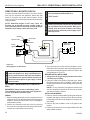
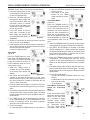
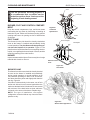
A remote wall switch and up to fifteen (15) feet of 18 Ga.
wire may be used with this appliance. Attach the wall
switch in a junction box at the desired location on the
wall. Figure 30. Do not extend beyond the wall switch wire
length provided.
NOTE: Extended lengths of wire may cause the
fireplace not to function properly. Longer length of
wire is permitted if the wire is made out of larger gauge
(diameter) wire. Always check with local code.
CAUTION
Remote Wall mounted Switch
WARNING
Millivolt - REMOTE WALL SWITCH INSTALLATION
KHLDV Series Gas Fireplace
Do not connect wall switch to a
110V circuit.
Electrical connections should only be performed
by a qualified, licensed electrician. Main power
supply must be turned off before connecting
fans to the main electrical power supply or performing service.
Sparker
Thermopile
Thermocouple
Pilot
Assembly
Piezo
Ignitor
OFF
ON
HI
ON
OFF
PILOT
LO
Switch
Optional 15’
Wall Switch
ON
OFF
Millivolt
Valve
WARNING
Figure 30 Wiring Diagram for Wall Switch
Before installing the blower, turn off the fireplace and allow to cool. Only a qualified service
person should service and repair the fireplace.
A qualified service person should connect and
disconnect the fireplace to gas supply. Follow
all local codes.
Optional Fan/Blower System FP2919
(BLOTKHL)
DV wiring
important: Always check local building codes.
This installation must comply with local regulations
as well as the National Electric Code.
WIRING
1. Before installing the blower, wire the receptacle into an
electrical circuit. This should be done before framing the
fireplace. Wire with minimum 60°C wire in accordance
with prevailing codes.
2. Remove the external junction box cover by removing
the screw from the right side of the outside firebox wall.
Junction box was installed at the factory.
24
3. The junction box cover has a factory installed “romex”
style strain relief connector. After connecting the wires,
route the wire leads through this connector. Refer to the
wiring diagram in Figure 31.
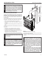
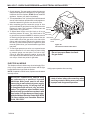
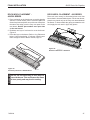
BEFORE INSTALLING BLOWER
1. Always turn off the gas supply and allow the unit to
cool before proceeding.
2. Clean the inside of the firebox (wall and floor), where
the blower and wires will be installed. Make sure the
firebox wall and floor are clean and dry before mounting
the blower.
diagram
NOTE: It is very important to arrange the blower wires
and wire assembly so that wires do not come in contact
with blower blades or firebox.
INSTALLING BLOWERS
1. Remove screen rod assemblies by lifting rod and pushing back and down to release rod from the three hooks
located behind the face of the fireplace on the right, left,
and middle.
2. Remove the plate located in front of the glass at the
bottom.
3. Rotate the access doors on the right and left side of the
glass toward the glass.
73D0024
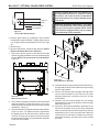
millivolt - OPTIONAL FAN/BLOWER SYSTEM
Junction Box
Figure 31 Junction Box Wiring Diagram
WARNING
Factory Supplied
Not Supplied
Failure to replace the access cover with the one
provided with the blower kit, and then running
the blower, will cause excessive temperatures
and could cause a fire, property damage and/or
loss of life.
WARNING
120V AC
60Hz
KHLDV Series Gas Fireplace
Electrical Grounding Instructions: This appliance is equipped with a three-prong (grounding)
plug for your protection against shock hazard
and should be plugged directly into a properly
grounded three prong receptacle.
4. Remove glass frame by releasing the three latches
located at the
top of the firebox. Tilt glass away from the
FP1912
unit, lift glass frame up and away from the unit. Page
Junction box wiring
45
8/08
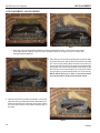
5. Remove logs.
6. Remove hearth brick, wall brick and rear brick. NOTE:
Remove brackets that secure wall brick.
7. Remove the access covers on the right and left side
walls of the firebox toward the front by unfastening the
screws. NOTE: The access covers are not identical.
Figure 32
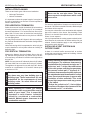
FP2233
Figure 33 Attach Blowers to Brackets
FP2233
blower
brackets
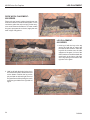
10. Assemble theattach
wire clips
provided
with the blower kit to
the right and left
sides of the fireplace through existing
1/09
Figure 32 Blower Access Covers
FP2136
FP2136
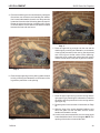
8. Two screws blower
are already
mounted
to each cover which
access
plates
would be utilized to mount the blower to the cover.
Unfasten the two screws and mount the blower bracket
assemblies. Figure 33
9. Consult blower wiring diagram and start the assembly.
Figures 31 & 34. It is helpful to wire the right blower,
the speed control, the fan limit switch, and the power
cord first. Then plug in the power cord to the junction
box and secure the right cover plate/blower assembly
to the side of the firebox.
73D0024
holes on right and left.
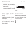
11. Run the wire harness down the right and snap wires
into the clips assembled in #10. Run the two wires
along the glass track, on the floor of the unit, in front
of the firebox
12. Snap the fan limit switch behind the clip already
assembled to the side of the firebox on the front right
hand side. Figure 35
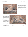
13. Secure the left access plate/blower assembly to the
left side of the firebox. Run the two wires mentioned
earlier up the left firebox wall and snap wires into clip
assembled in #10 on the outer shell wall. Make the
connection to the left blower. Replace the refractory
and hearth refractory (pull away from burner toward
the front).
25
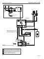
millivolt - OPTIONAL FAN/BLOWER SYSTEM
KHLDV Series Gas Fireplace
Blue
Junction Box
Blue
Black
Hi-Temp
Black
Hi-Temp
T-Stat Sensor
Black
Black
Right Blower
Left Blower
White
Black
Blower
Rheostat
Figure 34 Blower Wiring Diagram
18. Replace the front plate below the glass frame. NOTE:
The front plate hides the wire harness in the
front.
Remove Solid
Access Door
FP2135
blower wiring diagram
Bleu
Boîte de jonction
Clip
Firebox
Wall
FP2137
Noir
Hi-Temp
Figure 35 FP2137
Blower Access
Covers
Noir
Noir
Hi-Temp
Capteur t-stat
Ventilateur
Replace with Louvered Access
gauche
Door, Louvers Towards Bottom
blower access plates
14. Replace side panels attached to the glass frame
assembly with the louvered side panels provided with
Noir
Ventilateur
the blower kit by unfastening
the four nuts
for each
cover door. (Do not overtighten or studRheostat
may break
off.) Use three metal clip screws provided with kit to
secure the wire assembly in the front beneath the
access cover. Figure 36
15. Install the speed control (rheostat switch) on the side
above the existing one used for the light (discard the
plate sent with the switch as it will not be needed.
16. Replace logs.
17. Replace the glass.
26
Ventilateur
droit
Noir
Bleu
Blanc
Figure 36 Install New Louvers
FP2234
FP2234
install louvers
1/09
Figure 37 Location of White Dial on
Speed Control
73D0024
millivolt - OPERATING INSTRUCTIONS
KHLDV Series Gas Fireplace
WARNING
for your safety read before lighting
If you do not follow these instruction
exactly, a fire or explosion may result
causing property damage, personal
injury or loss of life.
A. This appliance is equipped with a pilot which must be lit with built-in piezo ignitor while following
these instructions exactly.
B. BEFORE OPERATING smell all around the appliance area for gas. Be sure to smell next to
the floor because some gas is heavier than air and will settle on the floor.
WHAT TO DO IF YOU SMELL GAS:
• Turn off all gas to the appliance.
• Open windows.
• Do not attempt to light any appliance.
• Do not touch any electric switch; do not use any phone in your building.
• Immediately call your gas supplier from a neighbor's phone. Follow the gas supplier's
instructions.
• If you cannot reach your gas supplier, call the fire department.
C. Use only your hand to push in, or turn the gas control knob. Never use tools. If the knob will
not push in or turn by hand, don't try to repair it. Call a qualified service technician. Force or
attempted repair may result in a fire or explosion.
D. Do not use this appliance if any part of it has been under water. Immediately call a qualified
service technician to inspect the appliance and to replace any part of the control system and
any gas control that has been under water.
WARNING
Lighting pilot for the first timE
initial lighting
Never use an open flame to
Purge air from the supply line as follows:
check for gas leak.
• Open main shutoff valve.
• Unscrew main pressure test point.
• Leave inlet test screw open until gas comes in.
• When gas is flowing, tighten inlet screw immediately.
leak testing
1. Follow the pipe from the gas supply line connection to the gas valve. Check connection for
leaks with soap and water mixture.
2. Next check for gas leaks at the burner with soap and water mixture.
3. Check the pilot for gas leaks with soap and water mixture.
73D0024
27
millivolt - OPERATING INSTRUCTIONs
KHLDV Series Gas Fireplace
approved leak testing method
You may check for gas leaks with the following methods
only:
• Soap and water solution
WARNING
Lighting pilot for the first time
If using a soap and water
solution to test for leaks,
DO NOT spray solution onto
control body.
• An approved leak testing spray
DANGER
• Electronic sniffer
NOTE: Remove any excessive pipe
compound from the connections.
Excessive pipe compound can set off
electronic sniffers.
Never check for gas leak with
open flame!
Check for gas leaks in each of the following locations:
• Pipe from the gas supply line connection to the gas valve
• Burner connections • Field made joints / gas shutoff valve
• Pilot • Factory made joints
• Each joint or connection
• All joints on valve and control body
WARNING
Lighting pilot
The control has an interlock device that does not allow the lighting of the fireplace
up to the moment the safety device of the flame has not interrupted the gas flow.
After that period of time (when the magnet is closed), it is possible to start the
lighting operation.
The gas control knob is designed to be operated by hand. DO NOT use any tools
during this operation. Damaged knobs may result in serious injury.
1. Depress and turn knob counterclockwise
to pilot position.
If the pilot does not stay lit, repeat steps 1 and 2.
F PILOT ON
OF
2. Depress fully and hold pilot gas knob. Depress
piezo igniter as many times as needed to ignite pilot.
Keep knob fully depressed for a few seconds.
Release and check that pilot continues to
burn.
PIL
Pilot Position
OT
Continued on next page
28
FP1935
control knob pilot 73D0024
millivolt - OPERATING INSTRUCTIONS
KHLDV Series Gas Fireplace
Lighting burner
Lighting the burner
Depress and turn the knob counterclockwise
to the “ON” position. It
will take less than four (4) seconds for the burner to ignite.
OFF
RS
The “ON/OFF/RS” switch for the main burner can be found behind door of
the fireplace. This switch allows you to turn on and to turn off the main burner
without using the gas valve knob. Make sure the button is in the “ON” position to light the main burner.
ON
main burner switch
On/Off/RS Switch
Pilot position
N
O
OFF P
Depress and turn knob to pilot position to keep burner off while maintaining
the pilot light.
ILOT PIL
OT
PILOT ON
F On Position
OF
Pilot Position
PIL
OT
FP1937
control knob on
FP1935 off gas
to turn
control knob pilot
Depress and turn knob clockwise
to “OFF” position.
ON O
FF PILOT
PIL
Off Position
73D0024
OT
29
SIGNATURE
COMMAND - CHECK GAS PRESSURE and ELECTRICAL INSTALLATION
KHLDV Series
Gas Fireplace
1. Check gas type. The gas supply must be the same as
stated on the appliance’s rating decal. If the gas supply
is different from the fireplace, STOP! Do not install the
appliance. Contact your dealer immediately.
2. To ease installation, a 24" (610 mm) flex line with manual
shut-off valve has been provided with on this appliance.
Install and attach 1/2" gas line onto shut-off valve.
3. After completing gas line connection, purge air from
gas line and test all gas joints from the gas meter to the
fireplace for leaks. Use a solution of 50/50 water and
soap solution or a gas sniffer.
4. To check gas pressures at valve, turn captured screw
counter clockwise 2 or 3 turns and then place tubing
to pressure gauge over test point. Turn unit to high.
Figure 38. After taking pressure reading, be sure and
turn captured screw clockwise firmly to reseal. Do not
over torque. Check test points for gas leaks.
Pressure Inlet
FP1909a
Pressure Outlet
Pilot Adjustment Screw
WARNING
Figure 38 Signature Command Valve
FP1909a
Do not use open flame to check for gas
leaks. signature command valve
alternate view
8/08
Electrical Wiring
WARNING
1. This fireplace is equipped with the Signature Control
valve which operates on 6 volts. The AC adapter plugs
into the fireplace junction box A/C power supply. Four
(4) “AA” batteries are used for back up during power
outages.
2. The Signature Command System can also be operated
without A/C power. The system can run on four (4) “AA”
batteries for approximately six (6) months under normal
use.
3. A/C power must be used to power the A/C module,
blowers, lights and AUX accessories used with this
fireplace.
Electrical connections should only
be performed by a qualified, licensed
electrician. Main power must be off when
connecting to main electrical power supply
or performing service. All wiring shall be
in compliance with all local, city and state
codes. The appliance, when installed, must
be electrically grounded in accordance with
local codes or in the absence of local codes,
with the National Electrical Code ANSI/NFPA
70 (latest edition) and Canadian Electrical
Code, CSA C22.1.
CAUTION
General
Label all wires before disconnecting when
servicing controls. Wiring errors can cause
improper and dangerous operation.
Optional Accessory Requirements
1. This fireplace may be used with a wall switch and/or
Signature Command wireless controls.
2. The command center control may be mounted on the
wall with the use of the SCSWEK 15ft. wall mount extension kit.
30
73D0024
ELECTRICAL INSTALLATION
KHLDV Series Gas Fireplace
JUNCTION BOX WIRING
1. This should be done before framing the fireplace. Wire the receptacle into an electrical circuit.
Wire with minimum 60° C wire in accordance with prevailing
codes.
2. Remove the external junction box cover by removing the
screw from the side of the outside firebox wall. Junction box
was installed at the factory.
120V AC
3. The junction box cover has a factory installed “romex” style
60Hz
strain relief connector. After connecting the wires, route the
wire leads through this connector. Refer to the wiring diaFactory Supplied
Not Supplied
gram in Figure 39.
Junction Box
Figure 39 Junction Box Wiring Diagram
The command center may be mounted on the wall with
the use of the SCSWEK Kit (15ft. cable, junction box,
wall cover).
Mount the junction box provided at the desired location
on the wall. Do not extend beyond the 15 ft. wire cable
provided. If a longer distance is required, the 15 ft. may be
extended up to 30 ft. maximum by using two (2) SCSWEK
cables plugged together.
Route the wire from junction box to lower control area
at bottom of fireplace. Unplug the 12" cable from the
command center. Attach the connector to the pins from
wire by pushing in to connector making sure to follow the
color code on connector. Plug the 15 ft. extension cable
into the 2 ft. cable. Remove command center from the
fireplace and plug the other end of the extension cable
into the command center. Snap on wall cover provided
and screw to junction box.
73D0024
FP1912
Junction box wiring
The wall switch wire connection is located off the 2 ft.
8/08
wire harness from
the control box to the command center.
WALL SWITCH INSTALLATION
Figure 40. The connection is labeled “Wall Switch”. Unplug
the male and female connectors and connect the two (2)
low voltage wires provided. Run wire to desired location
on wall. Up to 50 ft. of 18 ga. wire may be used if necessary. Attach wires to wall switch. Mount the wall switch in
to junction box and screw on cover.
WARNING
COMMAND CENTER WALL INSTALLATION
Do not connect wall switch to 110 V
circuit.
31
ELECTRICAL INSTALLATION
KHLDV Series Gas Fireplace
Light
300 Watt
Max
A/C Module
To Outlet
Pilot
Optional Blower
300 Watt
Max
Rear Burner Solenoid
300 Watt Max
RF Receiver
ON/OFF Button
A/C Module
Control Board
Black / Thermopile
Red / Thermopile
Sensor
Conversion
NG/LP
Ignitor / Sparker
Plug-in Connector
Control Board to Command Center
NOTE: Wall switch wires must
be connected together if a wall
switch is not being used.
Ground
OFF/LO
Plug-in Connector
Stepper Motor to
Control Board
LED
ON/HI
Master Switch
Command Center
Optional
Wall Switch
DC Power/Green
Plug-in Connector
Control Board to
Solenoid
Gas Out
Gas In
figure 40 Signature Command Wiring Diagram
Pilot Gas Tubing
CAUTION
Valve
32
Electrical connections should only be
FP2704electrician.
performed by a qualified, licensed
Main power supply must beSCS wiring diagram
turned off before
connecting fans to the main electrical power
supply or performing service.
73D0024
The black and white wires on the AC box
wiring harness are marked ‘Blower’, ‘Light’
and ‘Aux’. It is important to use the wires
marked ‘Blower’ or the control will not work
correctly.
WARNING
WARNING
Electrical Grounding Instructions: This
appliance is equipped with a three-prong
(grounding) plug for your protection against
shock hazard and should be plugged directly
into a properly grounded three-prong
receptacle.
NOTE
signature command - Optional fan blower system
KHLDV Series Gas Fireplace
Electrical connections should only be
performed by a qualified licensed electrician.
Main power supply must be turned off before
connecting the fan to the main electrical
power supply or performing service.
BLOTKHLSC SIGNATURE COMMAND BLOWER
To Junction Box
In Fireplace
AC Module
Light
WHITE
BLACK
Optional
AUX
{
{
WHITE
BLACK
BLACK
WHITE
GREEN
Connector
Pin To Contro l Box
Control Box
Blower (300w Max)
Figure 41 BLOTKHLSC Blower Wiring Diagram
The BLOTKHLSC Blower Kit requires the SCSACM A/C
Module and the TSFRSC remote to install and operate
this kit. Refer to blower instructions for installation and
remote instructions for operation.
FP2705
FP2684
BLOTKHLSC fan wiring
73D0024
33
signature command - OPERATING INSTRUCTIONS
KHLDV Series Gas Fireplace
WARNING
for your safety read before lighting
If you do not follow these instructions
exactly, a fire or explosion may result
causing property damage, personal
injury or loss of life.
A. This appliance is equipped with an ignition device which automatically lights the pilot. Refer
to the instructions.
B. BEFORE OPERATING smell all around the appliance area for gas. Be sure to smell next to
the floor because some gas is heavier than air and will settle on the floor.
WHAT TO DO IF YOU SMELL GAS:
• Do not attempt to light any appliance.
• Do not touch any electric switch; do not use any phone in your building.
• Immediately call your gas supplier from a neighbor's phone. Follow the gas supplier's
instructions.
• If you cannot reach your gas supplier, call the fire department.
C. Use only your finger to push in the master switch. Never use tools. If the switch will not function
by hand, do not try to repair it. Call a qualified service technician. Force or attempted repair
may result in a fire or explosion.
D. Do not use this appliance if any part of it has been under water. Immediately call a qualified
service technician to inspect the appliance and to replace any part of the control system and
any gas control that has been under water.
34
73D0024
signature command - OPERATING INSTRUCTIONS
KHLDV Series Gas Fireplace
OPERATing INSTRUCTIONS
1. STOP! Read the safety information above.
2. This appliance is equipped with an ignition device which automatically lights the burner. Do not try
to light the burner by hand.
3. With five (5) minutes to clear out any gas. Then smell for gas, including near the floor. If you smell
gas, STOP! Follow "B" in the safety information on Page 34. If you do not smell gas, go to next
step.
4. Press the master switch to the "ON" (-) position. Within eight (8) seconds it will beep once. This
indicates the system is ready.
5. Press "ON " button. Sparker will spark and pilot flame will light.
6. Once pilot flame is established, the main burner flame will light automatically.
7. If the pilot will not stay lit after several tries, turn the master switch to "OFF" and call your service
technician or gas supplier.
OFF
OFF
ON
Master
Switch
ON
Command Center
FP1913
FP1914
TO TURN
OFF GAS TO APPLIANCE
Switch
box
Pilot w sparker
8/08
8/08
1. Turn master switch to "OFF".
2. Turn off all electrical power to the appliance if service is to be performed.
73D0024
35
KHLDV Series Gas Fireplace
SIGNATURE COMMAND SYSTEM OPERATION INSTRUCTIONS
FEATURES
RF Receiver
ON/OFF
Command Center
To Thermopile
To Sensor
To Sparker
• Easy Access Function Operation and System Configuration
• Operation Confirmation/Fault Diagnostic Indications
(LED/Buzzer)
• ON/OFF/HI/Med/Low Operation
• Optional Wall Mounting
Control Board
• Electronic Ignition
• Pilot Lockout safety feature
• Electric Power Regeneration from Thermopile to save
•
•
•
•
•
•
•
battery
6-hour Automatic Shut Down Option
Convenient NG/LP Gas Type Conversion
Standing Pilot/Intermittent pilot Conversion
Previous settings Restoration Ability (Memory Off)
Uninterrupted Operation During Power Outage (Automatic Battery Backup)
ON/OFF RF Remote Receiver
Optional Transmitter Learn Capability
NG/LP
Conversion
To Command Center
Control
Board
To Stepper Motor
ON
LED
To Valve
Master Switch
OFF
AC Module
Battery Door
Command
Center
Figure 42 Signature Command System Components
AC Module Board (Requires TSFRSC Remote)
• Easy Snap-on Design
• Embedded Compact 120 VAC Adapter with Auto Battery Back up Feature
FP1917
• Remote Controlled 3-step Blower, Lighting, and On/Off Auxiliary AC Outputs
Transmitter (Optional)
TSFRSC
Signature components
Three Flame Height Settings
X
8/08
Low battery Indication for Transmitter X
Child Proof Lock-out
X
LCD Backlight
X
Security Codes 16
X
Countdown 6 hr Timer
X
Standard Thermostatic Control Mode
X
Smart Mode® Thermostat (Auto Flame & Blower Modulation)X
Three Brightness Settings for Lights X
Three Speed Control for Blower
X
On/Off AUX Rear Burner
X
Programmable Timer to turn blower on and off
X
BATTERY INSTALLATION
The Command Center uses four (4) "AA" batteries as back up for power outages. The system can operate for approximately six (6) months on battery power.
To Install Batteries (not included):
1. Press down the battery door tabs and pull out to remove battery door.
2. Install the batteries as indicated on Command Center.
3. Close battery door by snapping in place.
4. When the four (4) batteries are installed the system will operate without power.
5. The batteries should be replaced when the LED indicates low battery or at least once a year.
36
73D0024
SIGNATURE COMMAND SYSTEM OPERATION INSTRUCTIONS
SYSTEM CONFIGURATION/SETUP
All System configuration/setup is done on the Command
Center.
NOTE: When using On/Off wall switch, the switch must be
in the ON position to perform all configuration set ups at
the command center.
COLD CLIMATE OPTION
Choose the Mode That Best Suits Your Needs
The Signature Command System is designed to operate
in either Standing Pilot or Intermittent Pilot mode.
• The Standing Pilot Mode is best for colder climates
when the pilot must remain on continuously to prevent
condensation and ensure reliable operation.
• The Intermittent Pilot Mode is ideal for maximum effi-
ciency, igniting the pilot only when needed to start your
fireplace, lowering fuel consumption and reducing your
carbon footprint.
Either mode benefits from the instantaneous battery backup, so you never have to worry about a power outage.
NOTE: The Signature Command System comes standard in the Intermittent Pilot mode, so you must follow
the instructions below to switch to Standing Pilot Mode if
needed.
Intermittent/Standing Pilot Setup (Default intermittent)
1. Holding the ON button on the Command Center while
turning on the master switch will toggle between standing pilot and intermittent pilot.
2. After the above operation, one beep (for standing pilot) or two beeps (for intermittent pilot) will be given as
confirmation.
Six-hour Safety Shutdown Option (Default ON)
1. The system comes preset from the factory with a six
(6) hour shutdown from its last command of operation.
This is done to prevent the fireplace from continuing to
operate if unattended. You may disable this feature if
you wish.
NOTE: By disabling this feature, your fireplace may continue to operate unattended.
2. When the master switch is in the ON position (“-”), pressing the ON button and the OFF button on the Command
Center simultaneously will toggle between enabling and
disabling the six-hour shutdown option.
3. After the above operation, one beep (for enabling the
six-hour shutdown option) or two beeps (for disabling
the six-hour shutdown option) will be given as confirmation.
Remote Transmitter Learn Function (Default OFF)
1. The RF receiver button located on the Control Board
must be in the on position before the learn function can
begin. Use paper clip to depress button. One beep for
RF receiver ON or two beeps for RF receiver OFF will be
given as confirmation. Refer to Figure 42 for location.
2. After the RF receiver is on, holding the OFF button on
the Command Center while turning on the master switch
will activate the learn function for the transmitter.
3. After the above operation, two beeps will be given and
the green LED on the Command Center will flash for
10 seconds.
4. During the 10 seconds, press the OFF button on a
transmitter to learn. Another two beeps will be given
to confirm a successful learning. Refer to transmitter
instructions for remote operations.
Shutting Off the Standing Pilot (Temporary Shut Off)
To shut off the standing pilot for service or summer shut
down, press and hold the ON button on the Command
Center for 3 seconds when the master switch is in the ON
position (“-”) and the main burner is off.
Note: Pilot will resume the next time system is turned
on.
Key Combinations for System Settings
NOTE: When On/Off wall switch is used, it must be in the
On position to perform all system setups.
FunctionOperation
Intermittent/Standing
Hold the ON ▲ button while turning on the master switch
Pilot Setup
Standing Pilot Temp.
Shutoff
RF Remote Receiver
On/Off
Learn Remote
Transmitter
6-hour safety shutdown setup
73D0024
KHLDV Series Gas Fireplace
(Beep once for standing pilot, twice for intermittent pilot)
Hold the ON ▲ button 3 seconds (when the master switch
on the main burner is off)
Push the RF receiver On/Off button on the control board
Beep once for ON and beep twice for OFF
Hold the OFF ▼ button while turning on the master switch
(Beep twice then press any handheld remote button)
Press the ON ▲ button and OFF ▼ button simultaneously
(Beep once for ON, twice for OFF)
Default Setting
Intermittent
Pilot
RF OFF
ON
37
KHLDV Series Gas Fireplace
SIGNATURE COMMAND SYSTEM OPERATION INSTRUCTIONS
FUNCTIONS/OPERATION (with Command
Center)
Turning on the fireplace
1. Turn on the master switch and wait for a beep.
2. Press the ON button on the Command Center or turn
on wall switch. Pilot will light and burner will come on
High setting or last memory setting (See Turning Off
Fireplace below). For memory feature.
Pilot Safety Lockout Function
1. If the pilot doesn’t light after sparking for 30 seconds,
pilot trial lockout happens. The LED on the Command
Center flashes Green once every 2 seconds, until reset.
2. If the pilot flame is lost during normal operation, the
system will try three (3) times to relight after three (3)
failures, flame loss lockout happens. The LED on the
Command Center flashes Red-Green once every 2
seconds, until reset.
3. Turning the master switch on the Command Center to
the off position, then ON again will reset the system.
Flame Height Control
1. Press the ON button (on the Command Center) once to
turn on the main burner with maximum flame height.
2. Press the OFF button to decrease flame height. The first
two presses will decrease the flame height to medium
and low.
3. The third press on OFF will turn off the main burner. In
standing pilot configuration, the pilot will stay; in intermittent pilot configuration, the pilot will be shut off.
Turning the Fireplace Off
There are three ways to turn the fireplace off.
1. Flip the master switch to the off (“O”) position. (This will
turn the entire system OFF.)
2. Press the OFF button to Medium, Low, then Off.
3. Hold the OFF button anytime for three seconds or by
turning off the wall switch. These two commands of
OFF are (Memory Off) the system will remember all last
settings before turning off. The next time the fireplace is
turned on, all settings will resume. To reset, change to
the desired settings and shut off by using the Memory
Off commands and the system will be reset to those
new settings.
Command Center Operations:
The following functions are available on the Command
Center.
FunctionOperation
Power Up
Flip the master switch to the ON ("_") position to power up the system
Fireplace ON
Fireplace OFF
Flame Height Up
Flame Height Down
Press the ON ▲ button on the Command Center or turn on wall switch to turn the fireplace on
Flip the master switch to the OFF ("o") position OR press the OFF ▼ button 3 times OR for Memory Off, hold the OFF ▼ button 3 seconds, or turn off wall switch
Press the ON ▲ button once to turn on the fireplace with maximum flame height
Press the OFF ▼ button to lower the flame height to Medium and Low
Self Diagnostics Chart:
The Command Center has a self-diagnostic LED enabling you to troubleshoot problems and potentially avoid
a service call. Please refer to the charts below for indicator reference.
38
Fault
Conversion Cover Missing
Spark Fail
No Sensor Signal
Pilot Lockout - trial
Pilot Lockout - flame loss
Low Battery
No or Low Thermopile Power
Learning
AC Power On
Pressure Switch Failed (Power Vent only)
LED Indication
One RED (1 time)
Two RED (1 time)
Three RED (1 time)
One GREEN, every 2 sec. (until manual reset)
One RED-GREEN, every 2 sec. (until manual reset)
One RED, every 10s (continuously)
Two RED, every 10s (continuously)
GREEN Flashes, every 1 sec. (for 10 sec.)
GREEN solid
One RED every 2 sec. (until manual reset)
73D0024
WARNING
Information Bar
The information bar shows the room temperature, the
“sending signal” radio icon, the low battery indication icon,
the child-proof icon, and the flame icon. This area doesn’t
have touch buttons.
• The room temperature will always be shown after
•
•
•
•
power-up. It displays the room temperature from 40
°F to 99 °F. “Lo” and “HI” will be displayed when the
room temperature is lower than 40°F or higher than
99°F, respectively.
The radio icon will be shown when the transmitter is
sending a signal.
The low battery indication icon will be shown when
the battery voltage is low.
The child-proof icon will be shown when the childproof mode is activated.
The flame icon indicates the current flame height
- Off, Low, Medium and High
Touch Area
The touch area contains all touch buttons to control the
transmitter. It consists of two categories: menus and adjustment arrows. The blue LED backlight lights up for 8
seconds when any of the touch buttons is pressed.
• The menus include TIMER, THERMO, LIGHT, FAN
and AUX (Rear Burner Control).
• The adjustment arrows include ON/up and OFF/
down. Their default function is to adjust the flame
height. When a button from the menu is pressed,
the ON/up and OFF/down buttons will temporarily
become adjustment controls for the selected item.
When the adjustment is done, the ON/up and OFF/
down buttons go back to flame height controller
again.
73D0024
Adjustment
Controls
Figure 43 shows the display of the TSFRSC LCD.
Logo
Bar
n Function Areas of the LCD Display
Menus
Turn appliance OFF (at the Master Switch) if
you are away from your house for an extended
period of time. Never leave anything on top of
the surface of the transmitter.
Touch Area
Due to the sensitive temperature monitoring
components in the transmitter, it is necessary
to allow the transmitter to stabilize to room temperature before accurate room temperatures
are displayed. If the transmitter is activated
from a severe cold condition, allow 15 minutes
for accurate temperature readings to appear on
the LCD display.
KHLDV Series Gas Fireplace
Information
Bar
NOTE
TOUCH SCREEN REMOTE CONTROL OPERATION
Logo Bar
Function Areas of the LCD Display
Figure 43
The Logo Bar contains the brand logo: Signature Command System.
n Initialization and Setting up
FP2646
Installing Batteries:
TSFSC display
Figure 4
The remote transmitter has
two battery compartments,
one on each end of the transmitter. Always change all
four (4) batteries at the
same time.
Battery Door
Tabs
To install batteries,
1. Press down the battery
door tab and pull out to remove the battery door.
2. Install the batteries as inFigure 44
dicated inside the battery
compartments.
FP2607
3. Close the battery door by snapping
in place.
4. When all four batteries are installed,
the transmitter
install battery
will initialize for 5 seconds and then is ready for use.
5. The batteries should be replaced every 12 months or
when the low battery icon indicator is displayed.
Changing Temperature Unit
When batteries are installed in the transmitter,
1. All available icons on the LCD will be turned on then
be cleared.
2. The LCD will display temperature unit: °F. Use ON ∆
to toggle the units between °F and °C within the first 5
seconds.
3. The transmitter enters Manual Mode
4. The LCD displays room temperature with the chosen
unit.
39
KHLDV Series Gas Fireplace
TOUCH SCREEN REMOTE CONTROL OPERATION
Setting Privacy Code on Transmitter:
Figure 45
ON
The remote transmitter privacy code is preset in factory. In the event of activation or interference from other
nearby transmissions, change the
code using the following procedures
(learn function must be performed
after changing the code):
OFF
1. The RF receiver RF Receiver
button on the con- ON/OFF
trol board in the fireplace must be in the
on position before
the learn function
can begin. Figure
46. With the Command Center master switch in the ON
position, use paper
clip to depress the
Control Board
recessed button on
Control Board, one
Figure 46
beep for RF receiver ON or two beeps for RF receiver
OFF
2. Holding the OFF button on the Command Center while
turning on the master switch will activate the learn
function for the transmitter.
3. After the above operation, two beeps will be given and
the green LED on the Command Center will flash for
10 seconds.
4. During the 10 seconds, press the OFF button on the
transmitter to learn. Another two beeps will be given to
confirm a successful learning. Figure 47
40
FP2650
Battery Door
Command Center
Front Panel Bezel
Optional
Figure 47
FP2650
Do not use two (2) or more remote control syscommand
ctr ctrl brd
WARNING
1. Press the ON/arrow button and
the TIMER button at the same
time to enter privacy code setup
mode.
2. The setup display is shown in the
figure. The four digits on the top
stand for the privacy code (as the
actual DIP switches on Ambient’s
Figure 45
previous remotes). The default
values of the four digits will be all “1” (ON).
FP2649
3. The first digit will be flashing upon entering
the setup
setvalue
privace
code
mode. Push the ON button to toggle its
between
“0” (OFF) and “1”(ON), and push the “OFF” button
to jump to the next digit. The next digit will then start
flashing and the first one stops flashing. Set up the
four digits to your choice.
4. After setting up all the four digits, push “OFF” to finish
the process and return to the previous mode.
5. The Signature Command control board then needs to
re-learn the new setting.
Performing Learn Function
Master Switch
LED
tems in the same area with the same privacy
code setting, as they will communicate with
each other. This may cause the appliances to
malfunction.
Resetting the transmitter:
If the transmitter is not working properly, reinstall the batteries to reset the transmitter.
1. Pull out at least one of the batteries.
2. Press any key on the screen to discharge.
3. Wait for 10 seconds and reinstall the batteries.
Pushing and holding any key for more than 10 seconds
until the display refreshes will also reset the transmitter.
n Functions and Operations
General:
The TSFRSC Remote Control has four (4) operating
modes: Manual, Timer, Thermostatic and Smart Mode®
Thermostat. The control system can be set to temperature range between 45° F and 90° F. The blower speed
and flame height can be adjusted in the manual, timer
and thermostatic mode. The Smart Mode® thermostat
will automatically adjust flame height and blower speed
according to the difference between Set and Room temperatures.
The transmitter will operate the remote receiver from 1
foot to a maximum of 30 feet. The distance is reduced
FP2650
when batteries
low.
command
ctr ctrlare
brd
Manual Mode
Figure 48
In this mode, the TIMER button and the THERMO button will only display “TIMER” and “THERMO”, respectively without showing the time and the SET temperature.
Pressing the ON/up and OFF/down buttons will change
the flame height if none of the menu buttons (TIMER,
73D0024
TOUCH SCREEN REMOTE CONTROL OPERATION
THERMO, LIGHT, FAN, AUX) are pressed and flashing.
1. Press the ON/up button to turn
on the fireplace. The flame icon
on the LCD displays High.
2. Press the OFF/down button to
decrease the flame height and
turn off the fireplace. When the
OFF/down button is pressed
for three times, the flame icon
changes form High to Medium,
to Low, then to Off.
3. If the OFF button is held for
more than 3 seconds at any
flame height, the fireplace will
be turned off and the flame icon
Figure 48
disappears.
FP2651
4. Sliding up and down on the arrow buttons can also
Manual mode
turn on or turn off the fireplace.
5. If the fireplace is shut off using the above methods in 3
and 4, all the settings will be remembered and will be
resumed next time the fireplace
is turned on (Memory Off).
Timer Mode
Figure 49
Press the TIMER button to enter
timer mode. The fireplace will stay
on for a period of time as specified
by the timer and then be shut off
by the transmitter when the timer
counts down to zero.
1. When the TIMER button is
pressed, the Set Time appears
in the frame of the button and
flashes.
Figure 49
2. Use ON/up and OFF/down to
increase or decrease the Set TimeFP2652
in 15 min. increments, between 0:00 to 6:00. Sliding
up and
down on
Timer
mode
the arrow buttons will increase or decrease the Set
Time in 1 hour increments.
3. Push the TIMER button again to confirm the Set Time,
the transmitter sends an ON signal to turn on the fireplace.
4. The flashing stops and the ON/up and OFF/down buttons become flame height controller again. The flame
height will then stay as set up by the ON/up and OFF/
down buttons.
5. The TIMER button can be used when the transmitter is in Manual Mode or in Thermostat Mode. In both
modes, the fireplace will be shut down completely
when the timer counts down to zero.
6. To exit Timer Mode,
a. Push and hold the TIMER button for 3 seconds Or
73D0024
KHLDV Series Gas Fireplace
b. Use the OFF/down buttons to decrease the Set
Time to zero Or
c. Slide down on the arrow
buttons to exit TIMER
mode and shut off the fireplace.
Thermostat Mode
Figure 50
Press the THERMO button to
set the transmitter in thermostat
mode. The transmitter will automatically turn on the fireplace
when the room temperature is
below the set temperature and
turn off the appliance when the
room temperature is above the
set temperature within one degree.
Figure 50
FP2653
1. When the THERMO button is pressed, the Set temperthermo mode
ature appears in the frame of the button and flashes.
2. Use ON/up and OFF/down to increase or decrease
the Set temperature in 1 degree increments, between
45 degrees and 90 degrees. Slide up and down on the
arrow buttons will increase or decrease the Set Temperature in 10 degrees increments.
3. Press the THERMO button again to confirm the Set
Temperature. The transmitter will send out an On
signal or an Off signal depending on the relationship
between the Set temperature and the Room temperature.
4. The flashing stops and the ON/up and OFF/down buttons become flame height controller again. The flame
height will then stay as set up by the ON/up and OFF/
down buttons.
5. To exit Thermostat Mode:
a.push and hold the THERMO buttons for 3 seconds or
b.slide down on the arrow buttons to exit Thermostat mode and shut
off the fireplace.
Smart Mode® Thermostat
Option for Thermostat
Mode
Figure 51
Press and hold the THERMO button and the ON/UP
button at the same time
for 3 seconds to toggle
between Smart Mode®
thermostat and the regular Thermostat Mode.
The icon “Smart Mode”
will appear under the Set
Smart
Mode
Icon
FP2654
smart mode
Figure 51
41
KHLDV Series Gas Fireplace
TOUCH SCREEN REMOTE CONTROL OPERATION
Temperature. The transmitter will automatically adjust
the flame height according to the difference between the
Set temperature and the Room temperature. There is no
manual flame height adjustment. The fan speed will also
automatically adjust if turned on.
NOTE: When entering the Smart Mode® thermostat function there will be a 10 second delay for the flame and
blower adjustment. When Smart Mode® thermostat operates automatically there can be up to a 3 minute delay for
flame/blower adjustment. Smart Mode® thermostat checks
temperatures every 3 minutes. Also see AUX Control.
1. When Set Temp. is 3° F or higher than Room Temp.,
flame height will be on High.
2. When Set Temp. is 2° F higher than Room Temp.,
flame height will be on Medium.
3. When Set Temp. is 1° F higher than Room Temp.,
flame height will be on Low.
4. When Set Temp. is equal to Room Temp., flame height
does not change (stays on low).
5. When Set Temp. is lower than Room Temp., the fireplace will be shut off.
6. When Set Temp. is 1° F higher than Room Temp.,
again the flame height will be on Low.
7. the fan speed follows the flame height, if the fan is
turned on.
To exit Smart Mode® thermostat and shut off the fireplace;
a.push and hold the THERMO buttons for 3 seconds, Or
b.press the OFF button, Or
c.slide down on the arrow buttons.
To shut off the Smart Mode® thermostat option and return to regular
thermostat mode, press and hold
the THERMO button and the ON/
UP button at the same time for 3
seconds again.
Blower Speed Control
Figure 52
NOTE: Blower will only work with
flame on.
The blower speed control function
is used to adjust the speed of the
blower connected to the Signature
Figure 52
Command System. There are four
speed levels, Off, Low, Medium, High. FP2655
blower speed control
1. Press the FAN button to enter the blower speed control mode. The fan icon will start flashing.
2. Press the ON/up and OFF/down button to increase/decrease the blower speed.
3. Press the fan button again to confirm the speed set42
ting. If the fireplace is on, the blower speed will take
effect right away; if the fireplace is off, the receiver will
remember this setting and the blower is still off (see
blower On Delay and Off Delay in the next section).
4. After the signal is sent, the ON/up and OFF/down buttons become flame height controller again.
5. When the fan button is flashing, slide up and down on
the arrow buttons will turn the blower speed to High
or Off directly without pressing the fan button again to
confirm.
6. If the blower is turned on using the FAN button, the blower
speed will adjust automatically
when using Smart Mode (See
Smart Mode section).
Blower On Delay Time and Off
Delay Time Setup
Figure 53
1. Hold the FAN button for 3 seconds until two numbers appear on the LCD screen. The
left number is blower On Delay
and the right number is blower
Off Delay Time.
Figure 53
2. When the first number is flashing, use the ON/up button to set theFP2656
desired On Delay
Time from 0 to 15 min.
blower delay setup
3. Press the OFF/down button to jump to the Off Delay
Time setup.
4. When the second number is flashing, use the ON/up
button again to set the desired Off Delay Time from 0
to 15 min.
5. Press the OFF/down button again to finish the setup
and the new settings will be
transmitted to the receiver.
6. The default settings are 5
minutes for the On Delay
Time and 8 minutes for the
Off Delay Time, as shown.
Light Brightness Control
Figure 54
The light brightness control function is used to adjust the brightness of the light bulbs connected
to the AC module on the Signature Command System. There
are four light brightness levels
defined: Off, Low, Medium, High
Figure 54
1. Press the LIGHT button to enter FP2657
the light brightness
control mode. The LIGHT icon will Light
start flashing.
bright control
2. Press the On/up and OFF/down buttons to increase/
decrease the light brightness (Off-Low-Medium-High).
73D0024
TOUCH SCREEN REMOTE CONTROL OPERATION
3. Press the light button again to confirm the setting. The
new setting will be transmitted to the receiver.
4. After the signal is sent, the On/up and Off/down buttons become flame height controller again.
5. When the light button is flashing, slide up and down on
the arrow buttons will turn the light brightness to HIGH
or Off directly without pressing the light button
again to confirm
AUX Control (Rear Burner On/Off Control)
The AUX control function is used to turn on or turn
off the rear burner connected to the AC module
of the Signature Command System. Press the
AUX button to turn on or turn off the rear burner.
1. When the rear burner is turned on, the icon will beFP2658
come solid text and the “ON” icon will appear below
AUX
the “AUX” icon.
2. When the rear burner is turned off, the icon will become hollow text and the “ON” icon will disappear.
NOTE: If Smart Mode is entered when rear burner is off,
the rear burner will be turned on automatically; when the
transmitter is in Smart Mode, AUX button will be disabled.
See Smart Mode section for more information.
Setting up Blank
Screen or Constant Display in
Idle
Figure 55
There is an option to
set up how the LCD
displays and functions when the transmitter is in idle. There
are two choices:
Figure 55
1. A) Mode. When the transmitter is in idle, the icons in
FP2659 blower, light and
the “touch area” (timer, thermostat,
AUX) will disappear, as shown
in the
figure on the left.
blank
screen
When any of the touch buttons is pressed, those icons
will appear and are ready to operate (default).
2. B) Mode. The transmitter always displays all available
icons showing current status of timer, thermostat,
blower, light and AUX as shown in the figure on the
right.
Press TIMER and THERMO buttons at the same time for
3 seconds to toggle between A) and B).
1. When the current setting is A), touch any place in the
touch area to bring up the icons then press TIMER button and THERMO button at the same time for 3 seconds. The backlight will flash once to indicate that the
setting has changed to B).
2. When the current setting is B), pressing TIMER button
and THERMO button at the same time for 3 seconds
will switch to A) Mode. The touch area icons will disappear.
73D0024
KHLDV Series Gas Fireplace
n Safety Features
1. Low Battery Detection
When low battery condition occurs, the transmitter will
turn off the fireplace.
A)Battery voltage is checked every one minute. When the battery voltage is low, the
LCD displays a low battery icon which will
exist in all modes.
B)The transmitter will not operate with low
battery voltage. Change the batteries before the
FP2612
batteries become too weak for normal operations.
low batter
2. Power On Initialization
After the power-on initialization, the transmitter sends
a signal to turn off the fireplace.
3. Thermal Shutdown
When the ambient temperature is more than 99°F, the
transmitter will turn off the fireplace.
A)The LCD will display “HI”.
B)The Transmitter will not function until the room temperature has dropped below 99 degree
Fahrenheit.
4. Low Temperature Condition
When the ambient temperature is less
than 40 degrees Fahrenheit, the LCD will
display “LO”, and NO SIGNAL will be
FP2613
sent to turn on the appliance.
HI
All functions still remain the same for
both Manual Mode and Thermostat
Mode
5. Child-proof Protection
The child-proof icon will be shown when
the child-proof mode is activated by
pressing the ON button and the OFF
button at the same time for three seconds.
A)Enter childproof mode by pressing
and holding both the ON button and
the OFF butFP2614
ton simultaneously for 3 seconds. The Childproof
lo no child
indicator will be shown on the LCD.
B)Deactivate childproof mode by pressing and holding the ON button and the OFF button simultaneously for 3 seconds again. The Childproof indicator
disappears on the LCD.
C)The transmitter cannot be operated in childproof
mode.
43
TOUCH SCREEN REMOTE CONTROL OPERATION
KHLDV Series Gas Fireplace
n Using the Mounting Base
The transmitter comes with a mounting base which allows
you to hang the transmitter on the wall.
1. Secure the mounting base
on the wall with supplied
screws. For best viewing
angle, make it the same
height as your eyes.
2. Hang the transmitter on the
hook of the mounting base,
then push down so the
transmitter is flush to the
mounting base.
Figure 56
FP2674 TROUBLESHOOTING
mounting base
SymptomCausesAction
1.Battery icon on LCD on transmitter
1.Low Battery
1. Replace batteries. Change batteries
every 6 months.
2.LCD display is blank
2. Check battery installation or replace
batteries.
3.LCD display shows “funny” display
3. Reset the transmitter (see “Resetting the Transmitter” section).
4.Appliance does not come on
2.The transmitter did not match 1. Make sure the transmitter has
with the receiver learned to the receiver.
3.Transmitter measures temp-
1. Move transmitter to a cooler place
erature exceeding 99 degrees and wait until temperature drops
Fahrenheit and shows “HI” on below 99 degrees.
LCD
4.Distance between the transmitter 1. Make sure the opening distance is
and receiver is more than 30 feet less than 30 feet.
5.Blower is not on after the fireplace is
5.Blower setting is off
1. Press FAN key to select Fan speed
turned on you desire.
6.Blower delay setting is set too 1. Press and hold FAN key to set high desired ON/OFF delays. This is done
in minutes.
44
73D0024
glass removal
KHLDV Series Gas Fireplace
1. Remove the plate located in front of the glass at the
bottom.
2. Remove rod provided for screen assembly located
beneath the cover plate.
3. Rotate the access doors on the right and left side of the
glass toward the glass.
4. Remove glass frame by releasing the three latches
located at the top of the firebox. Tilt glass away from the
unit, lift glass frame up and away from the unit. Figure
57
CAUTION
Glass Frame Removal
Each clamp has a quick spring force. When
reinstalling clamps, keep fingers clear.
Glass Frame
FP2153
Figure 57 Remove Glass Frame
!
WARNING
FP2153
remove glass frame
HOT GLASS WILL
CAUSE BURNS.
DO NOT TOUCH GLASS
UNTIL COOLED.
NEVER ALLOW CHILDREN
TO TOUCH GLASS.
73D0024
45
final installation
KHLDV Series Gas Fireplace
BRICK, light bulb, and lens placement - 400/500 Series
BRICK, light bulb, and lens placement - 600 Series
1. Remove the trapezoidal light shroud located at the back
of the firebox by unfastening the three screws.
2. Disassemble the trapezoidal light shroud by unfastening
the four screws which secure the front to the back. Set
lens with the orange painted surface toward the bottom.
Center the lens right to left. Reassemble the front to the
back and set the side.
3. Place the right side panel by sliding it at an angle to clear
the grate. Set the panel straight up and bring forward
until it comes in contact with the reverse bend located
at the front of the firebox. Use one of the brackets and
screws provided to secure the panel in place.
4. Place the rear lower panel by setting it over the channel
behind the light socket. Make sure the grout line aligns
with the one on the side.
5. NOTE: Have the left panel bracket and screw handy
before installing the rear upper panel in place. Place
the rear upper panel in place by resting it over the rear
lower panel and sliding it behind the right side panel.
While holding the rear upper panel in place, slide the
left panel at an angle to clear the grate. Set the left side
panel straight up and release the rear upper panel.
Secure the left side panel in place using the second
bracket and screw provided in the kit.
6. Place the front hearth brick simultaneously and pull
toward the front away from the burner. This is critical
for balancing air flow around the front burner.
7. Install the halogen light bulb provided with the unit
(inside the log set). Do not touch light bulb directly with
fingers.
8. Replace the trapezoidal light shroud removed in step
#1 by sliding it over the light bulb and sockets. Be careful not to damage the light bulb. Align the holes on the
deflector with the hole on the rear channel and secure
in place.
1. Remove glass frame from fireplace.
2. Remove the six (6) screws securing each light box and
remove from unit. Figure 59
3. The light bulbs are included in the log packaging. install
the light bulbs into bulb sockets as shown in Figure 59.
CAUTION: Fingerprints or the transfer of oil from hands
will reduce the lifespan of the bulbs. It is advisable to
handle the light bulbs with a clean cloth.
4. The light lenses are included in the log packaging.
Remove the lens retainer brackets and install the light
lenses into the light box covers as shown in Figure
60.
Bulb Socket
Light Bulb
Light Box
Cover
FP2767
Figure 59 Remove Light Box Cover
FP2767
600Lens
series remove light cover
Lens Retainer
Bracket
Light Rheostat
Light
Black
White
FP2768
Black
Blue
Junction Box
Black
Connectors
Blue
White
White
Light
FP2154
Figure 58 Light Wiring Diagram for Millivolt Unit - 400/500 Series
Figure 60 Remove Lens Retainer Bracket
Light Box Cover
FP2154
Millivolt light wiring
46
73D0024
FP2768
final installation
KHLDV Series Gas Fireplace
ROCK WOOL PLACEMENT - 600 SERIES
rock wool placement 400/500 Series
1. Place rock wool on the front burner to provide glowing
embers. For best results, pull the rock wool apart into
dime size pieces and place on top of burner. Also place
the same size ember over the carry over parts on the
rear burner. Do not place embers over open slots
on the rear burner.
2. Distribute one layer of rock wool to cover the burner.
Figure 61
3. Place the logs on the burner. Refer to Log Placement
below. Light unit and after 15 minutes, check burner
flame and glow. Refer to Burner Flame, Page 53.
Place rock wool evenly in dime-sized pieces over front
burner both in front and behind grate. For the rear burner,
place the rock wool only on the carry-over areas between
the flames. To better enable the gas to permeate the rock
wool, apply the rock wool in light, fluffy pieces.
Figure 62 Rockwool Placement - 600 Series
FP2766
FP2766
600 rock wool
WARNING
Figure 61 Rockwool placement - 400/500 Series
FP2155
FP2155
ember placement
Do not use the entire bag of rock wool to
cover the burner. This could cause the flame
to burn poorly and may lead to sooting.
73D0024
47
log placement
KHLDV Series Gas Fireplace
lOG placement - 400/500 Series
LG593
Burner Grate Assembly
Step 1
LG594
1. Place
the rear log over the grate toward the back by positioning the holes over the large pins located
LG593
at the
right grate
and left. When the log is in place, the back surface of the log will come in contact with
KHLDV
LG594
the light trapezoid deflector.
KHLDV rear log
2. Place the log over the pilot by holding the log with the wide
end toward the back and the branch toward the front and
left. Set the log by having the protrusion on the bottom of
the log rest to the left side of the grate bar and behind the
pilot shield. Also set the notch located at the bottom of the
left branch over the second right tong on the grate. Make
sure that the log is positioned properly so it is not rocking.
NOTE: When the log is in place, it should not touch
the pilot but will be resting over the pilot shield.
Step 2
LG595
3. Place the leftLG595
front log in place by setting it over the left
side of the rear
log (match
KHLDV
rightprotrusion
front logto indentation), the
hearth brick and over the left tong on the grate. Match
the notch at the bottom of the branch with the tong on
the grate.
Step 3
48
LG596
KHLDV left front log
LG596
73D0024
log placement
KHLDV Series Gas Fireplace
4. Place the middle log over the two burners by setting the
flat surface over the burner and matching the indentation located underneath the branch over the protrusion
located at V-branch on the left front log placed in step #3.
Rotate the right end of the log clockwise until it comes
in contact with the reverse bend on the bracket located
between the front and rear burner.
Step 4
LG597
LG597
5. Place the upper left log at angle over the rear and the
KHLDV
middle
log the indentation on the bottom
middle
logs by
matching
of the log with protrusion on the rear log. Set the pointed
end of the log over the flat surface of the middle log.
When this log is in place the pointed end will come in
contact with the back of the pilot log placed in step #2.
LG598
Step 5
LG598
6. Place the right upper log over the pilot log and the hearth
KHLDV upper left log
brick by matching the indentation on the bottom of the
log with the protrusion on the pilot log.
Step 6
LG600
Step 7
73D0024
LG600
KHLDV upper right rear log
LG599
7. Place the upper right rear log over the rear log and the
right upper log by matching the indentations located at
the bottom with the protrusions on the rear log and the
right upper log.
8. Replace glass in reverse order of instructions on Page
LG599
45.
KHLDV
log inside the unit
9. Slide the rings
of theupper
screenright
provided
above the grate over the rod. Make sure the screen
handles are toward the center.
10.Hook the rod screen assemblies over the three hooks
located behind the face in front of the glass. NOTE: The
opening of the hooks are toward the back.
49
log placement
KHLDV Series Gas Fireplace
ROCK WOOL PLACEMENT 600 SERIES
Place rock wool evenly in dime-sized pieces over
front burner both in front and behind grate. For the
rear burner, place the rock wool only on the carryover areas between the flames. To better enable
the gas to permeate the rock wool, apply the rock
wool in light, fluffy pieces.
LG918
LOG PLACEMENT 600 SERIES
1. Hold log #1 with the key to the top
LG918 600 embers
and to the right side of center and
the notches on the bottom. Place the
log with the notches over the side
supports of the grate, in front of the
flame bracket on the left and with the
small notch in the lower, right front
of the log resting on the back of the
right tine of the grate.
LG919
2. Hold log #2 with the holes for the pin in
the back and notches toward the front
LG919
on the bottom. Position the log on the
Logof#1
pin provided on the back right600
corner
the grate fixture while placing the notch
on the key provided on the right side of
log #1.
LG920
LG920
600 Log #2
50
73D0024
log placement
KHLDV Series Gas Fireplace
3. Hold log #3 with the hole for the pin
toward the back left corner. Position
the log on the pin provided on the
back left corner of the grate. Place
the right end of the log in the notch
provided on the back left corner of
the grate. Place the right end of the
log in the notch provided on the top
of log #2. Insure the log is seated
securely.
4. Hold log #4 with the notch on the
bottom and toward theLG921
back of
the unit. Place the left end
the #3
600ofLog
log on the key provided on the
top of log #3. Rest the right end
of the log on the hearth brick just
to the right end of log #1.
5. Hold log #5 with the fat end
of the log to the left and the
detailed face of the log to the
front. Place the notch on the
bottom right end of the log onto
the key provided on the top of lot
#1, the left end of the log should
rest on the hearth brick just outside the right front corner of the
burner and grate. You may need
to hold log #5 in place until you
place lot #6.
73D0024
LG922
Log #5
Log #4
LG922
600 Logs 4 & 5
51
log placement
KHLDV Series Gas Fireplace
Log #6
LG923
Log #7
6. Hold log #6 in your right hand with
the charred detail to the right and the
notches on the bottom. Position the log
on top of the keys provided on the top
of log #5 in the front and log #3 in the
back. NOTE: Log #6 will help to hold
log #5 in place.
7. Hold log #7 with the pointed end to the
left and the notch on the bottom. Place
the pointed end of the log on the hearth
brick in front of the burner and under
the third time from the right. Rest the
notch on the bottom middle of the log
on the bend of the second tine from
the right. Slightly rotate the log forward.
The right end of the log does not quite
rest in the notch of log #1.
LG923
600 logs 6 & 7
LG924
600 andiron
52
73D0024
cleaning and maintenance
KHLDV Series Gas Fireplace
WARNING
Sensor
Turn off gas before servicing fireplace. It
is recommended that a qualified service
technician perform these check-ups at the
beginning of each heating season
Burner, Pilot and Control Compartment
Keep the control compartment, logs, and burner areas
surrounding the logs clean by vacuuming or brushing at
least twice a year. Make sure the burner porting, pilot air
opening and burner air opening are free of obstructions
at all times.
Thermopile
Signature
Command
System Pilot
FP2568
Pilot Flame
Thermocouple
The flames from the pilot should be visually checked as
soon as the heater is installed and periodically during
normal operation. The pilot flame must always be present when the fireplace is in operation. Figure 61. The
pilot flame has four distinct flames, one engulfing the thermopile, one engulfing the thermocouple or sensor, and the
remaining reaching to the main burners.
Thermopile
FP2568
pilot flame
burner
Inspect area around the injector. Remove any lint or foreign
material with a brush or vacuum.
Burner Flame
The flames from the burner should be visually checked
as soon as the heater is installed and periodically
during normal operation. In normal operation, at full
rate, and after operating for about 15 to 30 minutes,
the flame should be yellow and slightly taller than the
rear log. Figure 64
Millivolt Control
Pilot
FP1943
Figure 63 Pilot Flame
FP1943
pilot flame
If the flame is blue and only in the center, turn off unit
and let cool. After unit is cool, remove logs and check to
make sure the back holes in the burner are not covered
with rock wool. If the back holes are clear, add more
rock wool to the center of the burner. Replace logs.
NOTE: The type of installation, vent system
configuration, and wind effects may cause the flame
patterns to vary.
Figure 64 Burner Flame Appearance
LG601
LG601
flame appearance
73D0024
53
cleaning and maintenance
KHLDV Series Gas Fireplace
Venting SysteM
The fireplace and venting system should be inspected
before initial use and at least annually by a qualified field
service person. Inspect the external vent cap on a regular
basis to make sure that no debris is interfering with the
airflow. Inspect entire venting system to ensure proper
function.
Glass Door
Thoroughly clean the inside of the glass door after using
the fireplace for ten hours. Periodically clean the glass
door as necessary.
When cleaning the glass, remember:
• Do not remove the glass when hot. Allow glass to
•
•
•
•
•
•
cool before removal.
NEVER use abrasive materials.
Keep children and pets a safe distance away.
Never operate the fireplace without the glass door
properly secured.
Never operate the fireplace if the glass is broken.
Replace any glass that is chipped, cracked, or broken.
Replacement glass door assemblies MUST be supplied
by the fireplace manufacturer – No substitute materials may be used.
Handle glass door with care to avoid striking or scratching it on hard objects.
Logs
Leave logs installed in the fireplace for cleaning. Vacuum
surface of the logs with a brush attachment. If logs must be
removed for cleaning, handle carefully by holding gently at
each end. Gloves are recommended to prevent skin irritation from ceramic fibers. If skin becomes irritated, wash
gently with soap and water. Vacuum surface of logs with
brush attachment or brush logs with a soft bristle brush
(i.e. clean, dry paintbrush). To place logs back in the fireplace, see “Log Placement” found in the Final Installation
section.
NOTE: Do not use fluids to clean ceramic fiber logs.
Rock wool
Replace or add rock wool as required following installation instructions in the Final Installation section of this
manual.
To clean glass door, follow “Glass Removal” procedure
outlined in the Final Installation section. Film deposit on the
inside of the glass should be cleaned off using a nontoxic,
non-corrosive, non-abrasive, mild-cleaning solution. Simply
apply an adequate amount to the glass and wipe off with
a damp cloth. After all maintenance has been completed,
re-install glass door.
54
73D0024
troubleshooting
KHLDV Series Gas Fireplace
Standing Pilot Ignition
SYMPTOMPOSSIBLE CAUSEACTION
1. Spark ignitor will
A. Wire disconnected.
not light pilot after
repeated triggering of B. Defective ignitor.
piezo.
C. No gas or low gas pressure.
D. No Propane/LPG in tank
2. Pilot will not stay lit
A. Defective thermocouple
after carefully following lighting instructions.
B. Defective valve
3. Pilot burning, valve
A. Defective switch, wall
knob turned to “ON,”
switch, remote control or
switch is turned to
wire
“ON” or “RS,” but
burner will not ignite.
B. Pilot flame too small
C. Defective or malfunctioning thermopile
D. Defective valve
73D0024
A. Open door and check to make sure wire is connected to
ignitor.
B.Check for spark at electrode and pilot. If no spark and
electrode wire is properly connected, replace pilot
assembly.
C. Check remote/manual shut off valve from fireplace. Low
pressure can be caused by bent lines, restricted lines,
low pressure line pressure. Consult with plumber or gas
supplier.
D. Check Propane/LPG tank. Refill tank.
A. Check that thermocouple flame impinges on thermocouple. Clean and/or adjust pilot for maximum flame
impingement. Ensure that the thermocouple connection
at the gas valve is fully inserted and tight.
Disconnect the thermocouple from the valve, place one
millivolt lead wire on the tip of the thermocouple and the
other meter lead wire on the thermocouple copper lead.
Start the pilot and hold the valve knob in. If the millivolt
reading is less than 15 mV, replace pilot assembly.
B.If thermocouple is producing more than 15 mV, replace
faulty valve.
A. Check switch and wire for proper connection. Place
jumper wires across terminals of switch. If burner comes
on, replace defective switch.If the switch is OK, repeat
the same procedure on remote control If burner comes
on, replace remote control.
Place jumper wire across wire at gas valves (terminals
marked TH and TP/TH). If burner comes on, wires are
faulty or connections are bad. Replace wire.
B.If pilot flame is not close enough to the thermopile, adjust
pilot flame.
C.Check thermopile wire connections to make sure all
are tight and that the thermopile is fully inserted into
pilot assembly. Check thermopile with a millivolt meter.
Connect leads to TP and TP/TH terminals on the control
valve. If meter reading is below 325 mV, replace pilot
assembly.
D.Turn valve knob to “On” and switch to “ON.” Take a reading at the thermopile leads (TP & TP/TH) on the valve.
If the meter reads greater than 175 mV and the burner
does not light, replace defective valve.
55
troubleshooting
KHLDV Series Gas Fireplace
Standing Pilot Ignition
SYMPTOMPOSSIBLE CAUSEACTION
4. Frequent pilot
outage problem.
A. Pilot flame may be too high
or too low, causing pilot
safety to drop out
A. Clean and adjust the pilot flame for maximum flame
impingement on thermocouple.
5. The pilot and main
burner extinguish
while in operation
A. Inner vent pipe leaking
exhaust gases back into
system
B. Horizontal vent improperly
pitched
C. Improper vent cap installation
A. Check for flue product leak. Replace defective pipe
section.
6. Glass Soots
A.Flame impingement on logs A. Install log set per the instructions
Inspect the injector and air intake area. Make sure
this area does not have any blockage from debris and
clean.
Check gas supply.
7. Flame burn blue
and lifts off burner
(ghosting)
A.Insufficient oxygen being
supplied
56
B. Check horizontal-venting piping is running upward 1/4"
per foot. Do not run the pipe level or downward.
C. Check for proper installation and freedom from debris
or blockage.
A.Ensure that the vent cap is installed properly and free
of debris. Ensure that the vent system joints are tight
and have no leaks. Ensure that no debris has been
blocking the inner air intake at the bottom back of the
combustion chamber. Ensure that the glass is properly
secure and latch.
73D0024
troubleshooting
KHLDV Series Gas Fireplace
SIGNATURE COMMAND SYSTEM
OPERATION Install batteries and/or plug in the AC board FAULT No beep in about 8 seconds A Using battery? Make sure Command Center and the control board are connected by a 2 feet or 15 feet cable After the beep Flip the master switch (rocker switch) to the ON position Press the ON button on the Command Center No beep or no sound from the valve indicating pilot solenoid open B No sparking on the pilot C Sparking doesn’t continue D Pilot doesn’t light Main burner doesn’t light ACTION DIAGNOSIS E F Check NG/LP conversion cap and control board connections Check pilot connections Battery polarity wrong? Re-install batteries Battery voltage low? Change batteries AC plug is plugged to AC mains? Plug the AC plug to AC mains The 5-pin connector on the AC board broken or bent? Repair or replace the AC Board LED on the Command Center does not show solid green? Replace the AC Board Check valve connections Check grounding Check power supply (go through ) A Replace the Control Board or Command Center Go through B Sparking is happening elsewhere (under the pilot), re-install/replace the pilot The Control Board is having interference from the surrounding metal (Ground) Check gas supply Go through E Go through C The sensor on the pilot is not in the flame (pilot flame too small)? Re-install the Control Board, move it around or change the Control Board Sparking is not in the path of gas flow, adjust sparker position or replace the pilot Adjust sensor position or replace the pilot FP1911 troubleshoot sc 8/08 73D0024
57
REPLACEMENT PARTS
KHLDV Series Gas Fireplace
firebox components and accessories
2
3
1
6
11
5
9
12a,b
10
10
7a,b
8
Item
DescriptionQty.
KHLDV400
1. Bulb (100 Watt)
2
73D0020
730024
2. Bulb Socket
2
73D4521K
KHLDV firebox parts
3. Glass Frame Assembly
1
73D1015K
4. Junction Box Assembly (not shown)
1
26D2128K
5. Light Lens (400/500 Series)
1
73D0022
5. Light Lens (600 Series)
2
--
6. Panel, Access, Door
2
73D0029K
7a. Firebrick Set - Tavern Brown
1
FBKHLDV400TB
7b. Firebrick Set - Cottage Red
1
FBKHLDV400CR
8. Firebrick Set - Old English Herringbone
1
FBKHLDV400OE
9. Screen Rod
1
73D0010
10. Screen
2
73D0017
11. Front Cover
1
73D0520
Accessories / Field Installed Options
12a. T-Stat Blower with Speed Control (Millivolt system)
BLOTKHLTD
12b. SCS Blower w/ Time Delay
BLOTKHLSC
58
KHLDV500
73D0020
73D4521K
73D0159K
26D2128K
73D0022
--
73D0029K
FBKHLDV500TB
FBKHLDV500CR
FBKHLDV500OE
73D0010
73D0017
73D4524
KHLDV600
73D0020
73D4521K
20300592
26D2128K
-73D4057
73D0092
FBKHLDV600TB
FBKHLDV600CR
FBKHLDV600OE
20300611
20300612
20300600
BLOTKHLTD
BLOTKHLSC
n/a
BLOTKHLDVSC
73D0024
REPLACEMENT PARTS
KHLDV Series Gas Fireplace
Standing Pilot — Millivolt control
2I
2C
1
2T
3
2
6
4
5
7
10
8
11,12,13,14
730024
khldv mv valve parts
73D0024
59
REPLACEMENT PARTS
KHLDV Series Gas Fireplace
Standing Pilot – Millivolt Control
Item
1.
2.
2C.
2I.
2T.
3.
3.
3.
3.
4.
5.
6.
7.
7.
8.
8.
9.
10.
10.
11.
12.
13.
14.
15.
15.
DescriptionQty.
Gas Valve Assembly
1
Pilot Assembly
1
Replacement Thermocouple
1
Replacement Igniter w/wire
1
Replacement Thermopile
1
Tube, Rear, Venturi
1
Tube, Front, Venturi
1
Tube, Rear,Through-wall
1
Tube, Front, Through-wall
1
Flexhose w/Shutoff Valve
1
Rocker Switch
1
Piezo Igniter
1
Rear Injector
1
Front Injector
1
Rear Burner Assembly
1
Front Burner Assembly
1
Venturi
1
Wire Assembly
1
Wire Assembly
1
Accessories
On/Off Remote Control
1
Thermostatic Remote Control
1
Wall Switch Kit
1
Wall Thermostat Kit
1
Forged Andiron 13"
1
1
Cast Iron 12 /2"
1
KHLDV400NV
37D0117
20H2048
37D1067
37D1069
37D1068
73D0050
73D0562
73D0145
73D0146
69D0030
41D0048
14D0503
58D0102
57D0612
73D3270
73D3269
45D0600
44D0500
44D0501
KHLDV400PV
37D0118
20H2049
37D1067
37D1069
37D1068
74D0050
73D0562
73D0145
73D0146
69D0030
41D0048
14D0503
58D0052
58D0056
73D3270
73D3269
45D0600
44D0500
44D0501
KHLDV500NV
37D0117
20H2048
37D1067
37D1069
37D1068
54D0564
43D0185
73D0145
73D0146
69D0030
41D0048
14D0503
57D0679
56D3059
73D2368
73D3267
45D0600
44D0500
44D0501
KHLDV500PV
37D0118
20H2049
37D1067
37D1069
37D1068
54D0564
43D1085
73D0145
73D0146
69D0030
41D0048
14D0503
57D0680
62D3005
73D3268
73D3267
45D0600
44D0500
44D0501
TSMT / RCB / RCBE / RCMT / WMTD
TSST / RCST / RCT / RCSTE / RCSTEBA / RCSITEA / WWTD
MVWS
WT
FA113
CAI121/2
Fuel Conversion Kits - Millivolt Control
Natural Gas to LP
KHLDV400
KHLDV500
LP to Natural Gas
KHLDV400
KHLDV500
60
Kit #KHL400CKP
Kit #KHL500CKP
Kit #KHL400CKN
Kit #KHL500CKN
73D0024
REPLACEMENT PARTS
KHLDV Series Gas Fireplace
SIGNATURE COMMAND SYSTEM
400 Series
13
Venturi Gasket
8a
9
7a
6
15
8b
5a
5d
2
5c
Shield,
Pilot
1
7b
4
3
17, 18
5b
14
5e
Flex Hose
20H0022
Shield, Pilot
6
8a
3
8b
Flex
Hose
20H0022
7a
Venturi
Gasket
2
500 Series
14
5a
5d
13
17,18
1
3
15
9
7b
5b
5e
600 Series
8a
5c
1
6
8b
4
5a
2
7a
9
5b
Flex Hose
20H0022
7b
3
5g
16
15
5f
14
73D0024
61
REPLACEMENT PARTS
KHLDV Series Gas Fireplace
SIGNATURE COMMAND SYSTEM
Item
Desc.Qty.
1. Gas Valve Assembly
1
2. Pilot Assembly
1
3. Control Box, auxiliary shut-off
1
4. Command Center SCS
1
5a. Tube, Rear, Venturi
1
5b. Tube, Front, Venturi
1
5c. Rear Tube, Tee to Solenoid
1
5d. Rear Tube, Solenoid to Venturi
1
5e. Tube, Front, Through-wall
1
5f. Rear Tube, Solenoid to Union
1
5g. Front Tube, Tee to Union
1
6. Flexhose w/Shutoff Valve
1
7a. Rear Injector
1
7b. Front Injector
1
8a. Rear Burner Assembly
1
8b. Front Burner Assembly
1
9. Venturi
1
10. Wire Valve/Control Board SCS 1
(not shown)
11. Wire AC Module SCS (not shown) 1
12
Cable, CC/CB 24" SCS (not shown) 1
13. Remote Transmitter (full function) 1
14. AC Module
1
15. Solenoid (not shown)
1
16. Flame Baffle
1
KHLDV
400NTSC
80D0001
80D0039
80D0037
80D0005
73D349K
73D0562K
20300345
73D3528K
73D0146K
--
--
69D0030
58D0102
57D0612
73D3270
73D3269
69D1026
80D0010
KHLDV
400PTSC
80D0002
80D0040
80D0038
80D0005
73D3549K
73D0562K
20300345
73D3528K
73D0146K
--
--
69D0030
58D0052
58D0056
73D3270
73D3269
69D1026
80D0010
KHLDV
KHLDV
KHLDV
KHLDV
500NTSC 500PTSC 600NTSC 600PTSC
80D0001
80D0002 80D0001 80D0002
80D0039
80D0040 80D0039 80D0040
80D0037
80D0038 80D0037 80D0038
80D0005
80D0005 80D0005 80D0005
54D0564
54D0564 20301880 20301880
43D0185
43D0185 43D0185 43D0185
20300345 20300345
--
-73D3528K 73D3528K
--
-73D0146K 73D0146
--
---
--
20301881 20301881
--
--
20300615 20300615
69D0030
69D0030 69D0030 69D0030
57D0679
57D0680 20301817 20301958
56D3059
62D3005 20H3155 20H3146
73D3268
73D3268 20302746 20300556
73D3267
73D3267 20300555 20300555
69D1026
69D1026 69D1026 69D1026
80D0010
80D0010 80D0010 80D0010
80D0009
80D0008
TSFRSC
SCSACM
20301204
--
80D0009
80D0008
TSFRSC
SCSACM
20301204
--
80D0009
80D0008
TSFRSC
SCSACM
20301204
--
Accessories
Ref. DescriptionQty.
17. Forged Andiron 13"
2
17. Forged Andiron 16"
2
18. Cast Iron 121/2"
2
19. SCS Wall Extension Kit
1
(15' Wire, Rough-in Box, Wall Cover)
20. Decorative Door Kit
1
80D0009 80D0009 80D0009
80D0008 80D0008 80D0008
TSFRSC TSFRSC TSFRSC
SCSACM SCSACM SCSACM
20301204 20301204 20301204
--
20302747 20301814
KHLDV400
FAI13
FAI16
CAI121/2
SCSWEK
KHLDV500
FAI23
FAI16
CAI121/2
SCSWEK
KHL400ADBT
KHL500ADBT
KHLDV600
FAI23
FAI16
CAI121/2
SCSWEK
n/a
Fuel Conversion Kits - Signature Command System
Natural Gas to LP
KHLDV400
KHLDV500
KHLDV600
LP to Natural Gas
KHLDV400
KHLDV500
KHLDV600
62
Kit #KHL400CKPS
Kit #KHL500CKPS
Kit #KHL600CKPS
Kit #KHL400CKNS
Kit #KHL500CKNS
Kit #KHL600CKNS
73D0024
REPLACEMENT PARTS
KHLDV Series Gas Fireplace
logs KHLDV400 &
KHLDV500 LOGS
6
3
2
4
KHLDV600
LOGS
7
5
Item
1.
2.
3.
4.
5.
6.
7.
DescriptionQty.
Log #1
1
Log #2
1
730024
Log #3
1
600
log parts
Log #4
1
Log #5
1
Log #6
1
Log #7
1
73D0024
1
KHLDV400
73D0539
73D0540
73D0541
73D0542
73D0543
73D0544
73D0545
KHLDV500
73D0200
73D0201
73D0202
73D0203
73D0204
73D0205
73D0206
KHLDV600
20301946
20301947
20301948
20301949
20301950
20301951
20301952
63
REPLACEMENT PARTS
KHLDV Series Gas Fireplace
VENTing components
1
2
3
4
HO
T
10
5
6
9
7
8
730024
KHLDV vent parts
64
73D0024
REPLACEMENT PARTS
KHLDV Series Gas Fireplace
Venting Components for 5"x 8"
CurrentOld
Duravent
Duravent
or Vermont or Vermont Qty./Castings Group Castings Group Selkirk Metal-Fab
Item Box DescriptionPart no.Part no.Part no.Part no.
1
1 Horizontal Termination Cap w/Built-In Vinyl Siding
BHR58TK9
--
Standoff Heat Deflector, Firestop and Adjustable Pipe 11" to 145/8"
1
1 Horizontal Termination Cap Built-In Vinyl Siding Standoff,
BHS58TK
--
Heat Deflector, Firestop, 90° Elbow and Adjustable Pipe 11" to 145/8"
1
1 Horizontal Termination Cap w/Built-In Vinyl Siding Standoff,
BHSF58TK
--
Heat Deflector, Firestop, Flexible Pipe 20" to 48", Adapter
1
1 Horizontal Termination Cap Built-In Vinyl Siding Standoff,
KHLBHS58TK
--
Heat Deflector, Firestop, 90° Elbow and Adjustable Pipe 11" to 145/8", 24" Section of Pipe
1
8 Horizontal Termination w/ 1" Firestop
BHR58T/8
1
1 Horizontal High Wind Termination Cap
58DVA-HC
1285
5DT-HC
2
1 Horizontal Termination Cap
5DHT
2
1 Vertical Termination
*see below
*see below
5DT-VC
5DVT
2
1 Extended Vertical Termination
58DVA-VCE
1283
--
2
1 High Wind Vertical Termination
58DVA-VCH
1291
- 3
4 6" Pipe Length
58DVA-06
1208
5DT-06
5D6
3
4 9" Pipe Length
58DVA-09
1207
5DT-09
3
4 12" Pipe Length
58DVA-12
1206
5DT-12
5D12
3
4 24" Pipe Length
58DVA-24
1204
5DT-24
5D24
3
4 36" Pipe Length
58DVA-36
1203
5DT-36
5D36
3
4 48" Pipe Length
58DVA-48
1202
5DT-48
5D48
4
4 81/2" Pipe Extension
58DVA-08A
--
5DT-AJ
4
4 16" Pipe Extension
58DVA-16A
--
- 5
4 45° Elbow
58DVA-E45
1245
5DT-EL45 5D456
5
4 45° Swivel Elbow
--
--
5DT-EL45
6
4 90° Elbow
58DVA-E90
1290
5DT-EL90S 5D906
6
4 90° Swivel Elbow
--
1290G
5DT-EL90S
7
6 Flashing, 0/12 to 6/12 Roof Pitch
58DVA-F6
1243
5DT-AF6
5DF
7
Steep Roof Flashing
58DVA-F12
1243S
- 8
6 Storm Collar
58DVA-SC
1253
5DT-SC
5DSC
9
4 Firestop
58DVA-FS
1263
5DT-FS
5DFS
9
3" Firestop
FS38
FS38
- 10
1 Vinyl Siding Standoff
58DVA-VSS
1250
5DT-VS
5DVS
11
Attic Insulation Shield (not shown)
58DVA-IS
--
--
duravent 58DVA-VC/1280 vertical cap cannot be used with this fireplace.
For more information about, or instructions for, the venting
components referenced above, please contact the component
manufacturer:
Selkirk Corporation: www. selkirkcorp.com or 800-992-8368
Duravent: www. duravent.com or 800-835-4429
Metal-Fab, Inc.: www.metal-fabinc.com or 316-943-2351
73D0024
65
KHLDV Series Gas Fireplace
Requirements for the Commonwealth of
Massachusetts
This product must be installed by a licensed plumber or
gas fitter when installed within the Commonwealth of
Massachusetts.
Note Regarding Vented Products
Flex line installation must not exceed 36 inches and must
have a T shutoff valve.
Any residence with a direct vent product must have a CO
detector installed in the residence.
Installation of the fireplace or vented gas log in the State
of Massachusetts requires the damper to be permanently
removed or welded in the fully open position.
In addition, neither a naturally vented gas log nor a ventfree product may be installed in a bedroom or bathroom in
the State of Massachusetts.
All gas fitting and installation of this heater shall only be
done by a licensed gas fitter or licensed plumber.
For all side wall horizontally vented gas fueled equipment
installed in every dwelling, building or structure used in
whole or in part for residential purposes, including those
owned or operated by the Commonwealth and where the
side wall exhaust vent termination is less than seven (7) feet
above finished grade in the area of the venting, including but
not limited to decks and porches, the following requirements
shall be satisfied:
Installation of Carbon Monoxide Detectors
At the time of installation of the side wall horizontal vented
gas fueled equipment, the installing plumber or gas fitter
shall observe that a hard wired carbon monoxide detector
with an alarm is installed on each additional level of the
dwelling, building or structure served by the side wall
horizontal vented gas fueled equipment. It shall be the
responsibility of the property owner to secure the services
of qualified licensed professionals for the installation of hard
wired carbon monoxide detectors.
In the event that the side wall horizontally vented gas fueled
equipment is installed in a crawl space or an attic, the hard
wired carbon monoxide detector with alarm and battery
back-up may be installed on the next adjacent floor level.
In the event that the requirements of this subdivision can not
be met at the time of completion of installation, the owner
shall have a period of thirty (30) days to comply with the
above requirements; provided, however, that during said
thirty (30) day period, a battery operated carbon monoxide
detector with an alarm shall be installed.
Approved Carbon Monoxide Detectors
Each carbon monoxide detector as required in accordance
with the above provisions shall comply with NFPA 720 and
ANSI/UL 2034 listed and IAS certified.
Signage
A metal or plastic identification plate shall be permanently
mounted to the exterior of the building at a minimum height
66
of eight (8) feet above grade directly in line with the exhaust
vent terminal for the horizontally vented gas fueled heating
appliance or equipment. The sign shall read, in print size no
less than one-half (1/2) inch in size, “GAS VENT DIRECTLY
BELOW, KEEP CLEAR OF ALL OBSTRUCTIONS”.
Inspection
The state or local gas inspector of the side wall horizontally
vented gas fuelled equipment shall not approve the
installation unless, upon inspection, the inspector observes
carbon monoxide detectors and signage installed in
accordance with the provisions of 248 CMR 5.08(2)(a)1
through 4.
Exemptions
The following equipment is exempt from 248 CMR
5.08(2)(a)1 through 4:
• The equipment listed in Chapter 10 entitled “Equipment
•
Not Required To Be Vented” in the most current edition
of NFPA 54 as adopted by the Board; and
Product Approved side wall horizontally vented gas
fueled equipment installed in a room or structure
separate from the dwelling, building or structure used
in whole or in part for residential purposes.
MANUFACTURER REQUIREMENTS
Gas Equipment Venting System Provided
When the manufacturer of Product Approved side wall
horizontally vented gas equipment provides a venting
system design or venting system components with the
equipment, the instructions provided by the manufacturer
for installation of the equipment and the venting system
shall include:
• Detailed instructions for the installation of the venting
system design or the venting system components; and
• A complete parts list for the venting system design or
venting system.
Gas Equipment Venting System NOT Provided
When the manufacturer of a Product Approved side wall
horizontally vented gas fueled equipment does not provide
the parts for venting the flue gases, but identifies “special
venting systems”, the following requirements shall be
satisfied by the manufacturer:
• The referenced “special venting system” instructions
shall be included with the appliance or equipment
installation instructions; and
• The “special venting systems” shall be Product
Approved by the Board, and the instructions for that
system shall include a parts list and detailed installation
instructions.
A copy of all installation instructions for all Product Approved
side wall horizontally vented gas fueled equipment, all
venting instructions, all parts lists for venting instructions,
and/or all venting design instructions shall remain with
the appliance or equipment at the completion of the
installation.
73D0024
KHLDV Series Gas Fireplace
Limited lifetime warranty policy
Lifetime Warranty
The following components are warranted for life to the original owner, subject to proof of purchase:
Firebox, Combustion Chamber, Heat Exchanger, Grate and Stainless Steel Burners.
Five Year Warranty
The following components are warranted five (5) years to the original owner, subject of proof of purchase:
Ceramic Fiber Logs.
Basic Warranty
Vermont Castings Group warrants the components and materials in your gas appliance to be free from
manufacturing and material defects for a period of two years from date of installation. After installation,
if any of the components manufactured by Vermont Castings Group in the appliance are found to be
defective in materials or workmanship, Vermont Castings Group will, at its option, replace or repair the
defective components at no charge to the original owner. Vermont Castings Group will also pay for
reasonable labor costs incurred in replacing or repairing such components for a period of two years
from date of installation. Any products presented for warranty repair must be accompanied by a dated
proof of purchase.
This Limited Lifetime Warranty will be void if the appliance in not installed by a qualified installer in accordance with the installation instructions. The Limited Lifetime Warranty will also be void if the appliance
is not operated and maintained according to the operating instructions supplied with the appliance, and
does not extend to (1) firebox/burner assembly damage by accident, neglect, misuse, abuse, alterations,
negligence of others, including the installation thereof by unqualified installers, (2) the costs of removal,
reinstallation or transportation of defective parts on the appliance, or (3) incidental or consequential
damage. All service work must be performed by an authorized service representative.
This warranty is expressly in lieu of other warranties, express or implied, including the warranty of
merchantability of fitness for purpose and of all other obligations or liabilities. Vermont Castings Group
does not assume for it any other obligations or liabilities in connection with sale or use of the appliance.
It states that do not allow limitations on how long an implied warranty lasts, or do not allow exclusion
of indirect damage, those limitations of exclusions may not apply to you. You may also have additional
rights not covered in the Limited Lifetime Warranty.
Vermont Castings Group reserves the right to investigate any and all the claims against the Limited
Lifetime Warranty and decide upon method of settlement.
IF WARRANTY SERVICE IS NEEDED...
1. Contact your supplier. Make sure you have your warranty, your sales receipt and the model/serial
number of your Vermont Castings Group product.
2. DO NOT ATTEMPT TO DO ANY SERVICE WORK YOURSELF.
73D0024
67
Based on CSA P.4.1-09
Efficiency Ratings
ModelEnerGuide Ratings
Fireplace Efficiency (%)
KHLDV400NV
69.6
KHLDV400PV
78.2
KHLDV400NTSC
Recherchez dans la73.2
brochure
KHLDV400PTSC
82.2
les caractéristique de rendement
KHLDV500NV
75.2au gaz
énergétique de foyer
KHLDV500PV
69.8
Énerguide
KHLDV500NTSC
78.5
Based on CSA P.4.1-09
Selon CSA P.4.1-09
KHLDV500PTSC
71.8
KHLDV600NTSC
81.0
KHLDV600PTSC
80.0
Vermont Castings Group
149 Cleveland Drive • Paris, Kentucky 40361
www.vermontcastingsgroup.com