1
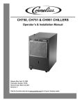
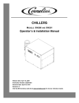
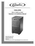
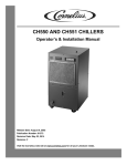
CHILLERS
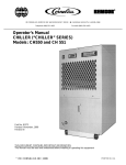
MODELS: CH750, CH751 & CH951
Operator’s & Installation Manual
Release Date: April 19, 2002
Publication Number: 91256
Revision Date: May 5, 2010
Revision: D
Visit the IMI Cornelius web site at www.cornelius.com for all your Literature needs.
CH SERIES CHILLER
OPERATOR’S & INSTALLATION MANUAL
The products, technical information and instructions contained in this manual are subject
to change without notice. These instructions are not intended to cover all details or variations of the equipment, nor to provide for every possible contingency in the installation,
operation or maintenance of this equipment. This manual assumes that the person(s)
working on the equipment have been trained and are skilled in working with electrical,
plumbing, pneumatic and mechanical equipment. It is assumed that appropriate safety
precautions are taken and that all local safety and construction requirements are being
met, in addition to the information contained in this manual.
To inquire about current revisions of this and other documentation or for assistance with
any Cornelius product contact:
www.cornelius.com
1-800-551-4423
This document contains proprietary information and it may not be
reproduced in any way without permission from Cornelius.
Printed in U.S.A.
Copyright © 2002-2010, All Rights Reserved, IMI Cornelius Inc.
Introduction . . . . . . . . . . . . . . . . . . . . . . . . . . . . . . . . . . . . . . . . . . . . . . . . . . . . . . . . . . . . . . . . . . . . .
Specifications. . . . . . . . . . . . . . . . . . . . . . . . . . . . . . . . . . . . . . . . . . . . . . . . . . . . . . . . . . . . . . . . . . . .
Installation Instructions . . . . . . . . . . . . . . . . . . . . . . . . . . . . . . . . . . . . . . . . . . . . . . . . . . . . . . . . . . .
Location . . . . . . . . . . . . . . . . . . . . . . . . . . . . . . . . . . . . . . . . . . . . . . . . . . . . . . . . . . . . . . . . . . . . . .
Plumbing . . . . . . . . . . . . . . . . . . . . . . . . . . . . . . . . . . . . . . . . . . . . . . . . . . . . . . . . . . . . . . . . . . . . .
Electrical . . . . . . . . . . . . . . . . . . . . . . . . . . . . . . . . . . . . . . . . . . . . . . . . . . . . . . . . . . . . . . . . . . . . .
Start-Up/Operation. . . . . . . . . . . . . . . . . . . . . . . . . . . . . . . . . . . . . . . . . . . . . . . . . . . . . . . . . . . . . . . .
Standard Thermostat Eliwell IC902 . . . . . . . . . . . . . . . . . . . . . . . . . . . . . . . . . . . . . . . . . . . . . . . . .
Maintenance . . . . . . . . . . . . . . . . . . . . . . . . . . . . . . . . . . . . . . . . . . . . . . . . . . . . . . . . . . . . . . . . . . . . .
Service . . . . . . . . . . . . . . . . . . . . . . . . . . . . . . . . . . . . . . . . . . . . . . . . . . . . . . . . . . . . . . . . . . . . . . . . .
Removing Wrapper . . . . . . . . . . . . . . . . . . . . . . . . . . . . . . . . . . . . . . . . . . . . . . . . . . . . . . . . . . . . .
Replacing Switch . . . . . . . . . . . . . . . . . . . . . . . . . . . . . . . . . . . . . . . . . . . . . . . . . . . . . . . . . . . . . . .
Replacing Fan Blade and/or Motor . . . . . . . . . . . . . . . . . . . . . . . . . . . . . . . . . . . . . . . . . . . . . . . . .
Replacing Pump. . . . . . . . . . . . . . . . . . . . . . . . . . . . . . . . . . . . . . . . . . . . . . . . . . . . . . . . . . . . . . . .
Fluid Recommendations . . . . . . . . . . . . . . . . . . . . . . . . . . . . . . . . . . . . . . . . . . . . . . . . . . . . . . . . . . .
Troubleshooting. . . . . . . . . . . . . . . . . . . . . . . . . . . . . . . . . . . . . . . . . . . . . . . . . . . . . . . . . . . . . . . . . .
Parts List. . . . . . . . . . . . . . . . . . . . . . . . . . . . . . . . . . . . . . . . . . . . . . . . . . . . . . . . . . . . . . . . . . . . . . . .
Warranty . . . . . . . . . . . . . . . . . . . . . . . . . . . . . . . . . . . . . . . . . . . . . . . . . . . . . . . . . . . . . . . . . . . . . . . .
1
1
1
1
1
1
2
2
3
3
3
3
3
3
4
5
6
8
CH Series Chiller Operator’s & Installation Manual
INTRODUCTION
The Cornelius “CH” Series Water Chillers (Models CH750-A, CH751-A, and CH951-A) are specifically designed
to cool clean liquid before it is circulated to the cooling application. The Unit includes a complete refrigeration
system and associated controls housed in a sturdy sheet metal enclosure with perforated panels for air
circulation. Options include a reservoir and a choice of pumps and temperature controls to provide a self–
contained liquid cooling/circulation system tailored to a particular closed loop or tank cooling application.
On closed loop systems, the Unit is provided with a pump and reservoir for recirculation of water from the chiller
to the process. On tank cooling systems, the Unit is provided without the reservoir and the pump is optional for
recirculation of water from the chiller to the tank. Control temperature is sensed on the outlet of the chiller for
closed loop systems and it is sensed on the inlet of the chiller for tank cooling systems.
The pump options consist of a small magnetic drive pump as standard with a variety of magnetic drive and
positive displacement pumps available for particular flow and pressure requirements. An optional bypass valve is
available for the pump circulation system. (This valve is standard on Units utilizing the positive displacement
pumps). This can be used to adjust pump flow and pressure to match process requirements. This valve also
allows internal recirculation within the chiller in the event the chiller outlet is obstructed.
SPECIFICATIONS
CH750-A
CH751-A
CH951-A
3/4
3/4
1
115/1/60
230/1/60
230/1/60
F. L. A. (Amps)
19
9.5
10
Reservoir Capacity (Gal)
5
5
5
3.5
3.5
4.0
Condensing Unit Horse Power
Electrical (Volts/Phase/Hz)
Refrigerant 134-A Charge (Lbs)
Stainless Steel Connections
3/4-inch FPT
3/4-inch FPT
40-100 F
40-100oF
250
250
250
Dimensions:Depth (inches)
24-1/2
24-1/2
24-1/2
Width (inches)
18-1/8
18-1/8
18-1/8
Height (inches)
30-1/2
30-1/2
30-1/2
Net Weight (Lbs.)
o
3/4-inch FPT
40-100 F
Operating Water Temp. Range
o
INSTALLATION INSTRUCTIONS
LOCATION
Locate the chiller indoors in a well ventilated area with ambient temperatures in the range of 65° F to 100° F.
Allow a minimum of six inches of clearance around the chiller for proper air circulation. Avoid hot air discharge
from other equipment or enclosed areas where heat could build up and cause a rise in ambient temperature.
PLUMBING
Follow standard plumbing practices and local codes in making water connections. Piping that is exposed to high
ambient temperatures may need to be insulated to prevent condensation and/or significant liquid heat gain.
ELECTRICAL
All wiring must conform to the National Electric Code and any applicable local codes. The chiller must be:
© 2002-2010, IMI Cornelius Inc.
-1-
Publication Number: 91256
CH Series Chiller Operator’s & Installation Manual
1.
2.
Permanently wired by means of conduit from the junction box on the rear of the chiller cabinet to a
properly fused disconnect of proper amperage or;
Wired to a properly rated power cord and plugged into an outlet with appropriate disconnect and
amperage rating.
START-UP/OPERATION
Before the Unit can be operated, it is important that the circulating system be filled with water (See Fluid
Recommendations page). On systems with a reservoir, ensure that the drain plug is in place and the plug is
secure. Fill the reservoir through the fill port with clean water. The water level sight glass on the front panel will
indicate “Full” when enough water has been added. Once full, make the final connection to the inlet and outlet of
the chiller. On system without a reservoir, the pump should be primed before operation. Attach a water source to
the inlet of the chiller and fill the Unit with clean water. The system is filled when the water can be seen flowing at
the chiller outlet. Once full, make the final connection to the inlet of the chiller.
Turn the power switch to the “On” position. The switch will light indicating power to the Unit and the pump
operates, the thermostat can be adjusted to the proper setpoint.
STANDARD THERMOSTAT ELIWELL IC902
The following procedure should be followed to adjust the Eliwell IC902 thermostat temperature setting:
To set the SET POINT, press and release the SET button. SET displays.
Press the SET button again, the current SET POINT is displayed. Press the UP or DOWN button to
change the SET POINT to the desired temperature.
3. Press the fnc button twice to exit the program. The current liquid temperature is displayed.
The thermostat has a range that is pre-set at the factory. The range is 40° F (5° C) to 100° F (38° C). If operation
outside of this range is required, please contact the Cornelius Technical Service Department.
1.
2.
out1
oF
fnc
set
Figure 1. Control Panel
When the flow rate to the process is critical, a flow meter and valve should be installed in the line in order to
obtain the proper flow rate.
Once these start-up procedures are complete, the chiller is ready for standard operation.
NOTE: Never operate the chiller with enclosure panels removed.
Always use the illuminated switch to turn off the chiller when it is not being used.
Always ensure that all air inlets and outlets are free of obstructions.
Publication Number: 91256
-2-
© 2002-2010, IMI Cornelius Inc.
CH Series Chiller Operator’s & Installation Manual
MAINTENANCE
WARNING: Disconnect electrical power from the unit before performing any of the
following maintenance procedures.
The chiller requires very little normal maintenance. The condenser fins should be cleaned by blowing
compressed air through the condenser. from the fan side as required to prevent blockage of air flow by dirt and
debris that may accumulate over time. The positive displacement pump motor should be lubricated with ten drops
of SAE 10 oil once each year. The circulation system should be drained and flushed periodically to avoid build up
and possible restriction of flow by contaminants. Following these simple procedures will ensure many trouble free
hours of chiller operation.
SERVICE
Service of the chiller is limited to replacing the switch, the thermostat, the fan motor, and the pump. Charging and
other refrigeration problems must be performed by a qualified refrigeration technician.
REMOVING WRAPPER
1.
2.
Disconnect electrical power from the Unit.
Remove the seven screws from each side of the wrapper and the two screws that secure the
wrapper to the front and back panels. Retain all hardware and lift the wrapper off the Unit.
REPLACING SWITCH
1.
2.
3.
4.
5.
Remove the wrapper as described above.
Remove the spade lugs from the existing switch and note connection points.
Remove the switch from the front panel.
Install the new switch in the front panel and connect the leads to the new switch.
Install the wrapper.
REPLACING FAN BLADE AND/OR MOTOR
1.
2.
3.
4.
5.
6.
7.
Remove the wrapper as described above.
Remove the screws securing the fan guard to the fan shroud.
Remove the conduit connection at the back of the motor and disconnect the wire leads.
Remove the bolts securing the fan mounting bracket to the base and remove the fan/motor
assembly.
Separate the fan blade from the motor and install the new blade or motor.
Re-install the fan mounting bracket and fan guard. Re-connect the wire leads and conduit
connection.
Install the wrapper.
REPLACING PUMP
1.
2.
3.
4.
5.
6.
7.
Remove the wrapper as described above.
Remove the clamps and hoses from the suction and discharge of the pump.
Remove the screws securing the pump to the base.
Disconnect the wire leads from the pump motor and remove the pump.
Remove all fittings from the pump and install them on the new pump.
Install the pump and re-connect wire leads and hoses.
Install the wrapper.
© 2002-2010, IMI Cornelius Inc.
-3-
Publication Number: 91256
CH Series Chiller Operator’s & Installation Manual
FLUID RECOMMENDATIONS
Cornelius chillers are designed to operate with water to provide maximum performance for temperatures of 40° F
(4.4° C) to 100° F (37.8° C).
Distilled Water
Acceptable
De-Ionized Water
(1-5 Meg ohms)
Acceptable
De-Ionized Water
(5+ Meg ohms)
Acceptable with Stainless Steel & PVC only (No Copper
or Brass)
Propylene Glycol
(Lab & Industrial Grade)
Acceptable - 30% Glycol/70% Water
(For Applications with Temperatures below 40° F)
Lab & Industrial Grade Ethylene Glycol
Acceptable - 30% Glycol/70% Water
(For Applications with Temperatures below 40° F)
NOT Acceptable
Mineral/Hydraulic Oils
(Commercial/Automotive Antifreeze)
(Silicate Rust Inhibitors in Automotive/Commercial antifreeze damages pump seals and housing which lead to
failure.)
Acidic/Basic Solutions
(Above 8 or below 6 PH)
Not Acceptable
Mineral/Hydraulic Oils
(Viscosity > 50 Centistrokes)
Not Acceptable
For questions regarding special or other fluids contact IMI Cornelius at 1-800-551-4423.
To purchase Lab or Industrial Glycol contact:
IMI Cornelius, 1-800-551-4423 - Part No. 111521000, 5 Gal.
Publication Number: 91256
-4-
© 2002-2010, IMI Cornelius Inc.
CH Series Chiller Operator’s & Installation Manual
TROUBLESHOOTING
Trouble
Chiller does not operate, Power
Light “OFF”
No Circulation of Chilled Water
Inadequate Cooling
Problem Cause
Remedy
A. No Power to unit
A. Check main disconnect fuses,
wiring and power lead to unit.
B. Loose or poor wire connection
B. Check wiring. Correct loose or
poor wire connection
C. Defective Control Power Switch C. Replace Switch
D. Overload device open.
D. Allow compressor to cool, then
install new overload device;
replace compressor if necessary.
E. Inoperable relay.
E. Replace relay.
F.
F.
Low input voltage
Nominal voltage +/- 10% is
required.
A. Line to or from chiller is
restricted.
A. Inspect lines and remove any
obstructions.
B. Low water level.
B. Ensure that tank is full.
C. Inoperable pump.
C. Check for obstruction or binding
impeller., replace pump and/or
motor, if necessary.
A. Condenser is restricted.
A. Clean condenser.
B. Fan motor not operating freely.
B. Replace fan blade and/or motor
if necessary.
C. Water not circulating
C. See “No Circulation of Chilled
Water”
D. Unit low on refrigerant.
D. Charge system with refrigerant.
E. Inoperative temperature control. E. Replace thermostat.
© 2002-2010, IMI Cornelius Inc.
-5-
Publication Number: 91256
CH Series Chiller Operator’s & Installation Manual
PARTS LIST
Figure 2. CH750, CH751 and CH951 Exploded View
Table 1.
Item
No.
1
2
3
4
5
6
7
Part No.
31934
31935
32386
620603707
62063706
620603711
620603712
620603713
*
Not Used
620603703
620603704
620603705
Publication Number: 91256
Description
Switch, Illuminated (115V)
Switch, Illuminated (230V)
Thermostat, Eliwell No. EWPC902
Blade, Fan (CH750, CH751)
Blade, Fan (CH951)
Motor, Fan (CH750)
Motor, Fan (CH751)
Motor, Fan (CH951)
Condenser
Compressor (CH750)
Compressor (CH751)
Compressor (CH951)
-6-
© 2002-2010, IMI Cornelius Inc.
CH Series Chiller Operator’s & Installation Manual
Table 1.
Item
No.
Part No.
Description
8
9
*
Relay
*
Capacitor
61001
TXV CH750, CH751
10
61003
TXV CH951
11
60514
Sight Glass
12
60502
Control, Low Pressure
13
60204
Filter Drier
14
*
Receiver
15
Not Used
16
*
Pump, Circulating
17
32378
Transformer, Thermostat
32606
Relay (115V)
18
32607
Relay (230V)
* Contact the Service Dept. for the Appropriate Part Numbers.
© 2002-2010, IMI Cornelius Inc.
-7-
Publication Number: 91256
Ice Frost Operator’s Manual
WARRANTY
IMI Cornelius Inc. warrants that all equipment and parts are free from defects in material and workmanship under
normal use and service. For a copy of the warranty applicable to your Cornelius or Wilshire product, in your
country, please write, fax or telephone the IMI Cornelius office nearest you. Please provide the equipment model
number, serial number and the date of purchase.
Publication Number: M620919596OPR
-8-
© 2004-2007, IMI Cornelius Inc.
IMI Cornelius Inc.
www.cornelius.com