1
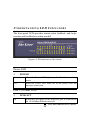
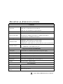
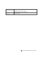
Ether-FSH2402NT
24+2 Mixed Giga port Switch
User’s Manual
FCC Warning
This equipment has been tested and found to comply with the
regulations for a Class A digital device, pursuant to Part 15 of the
FCC Rules. These limits are designed to provide reasonable
protection against harmful interference when the equipment is
operated in a commercial environment. This equipment generates,
uses, and can radiate radio frequency energy and, if not installed
and used in accordance with this user’s guide, may cause harmful
interference to radio communications. Operation of this
equipment in a residential area is likely to cause harmful
interference, in which case the user will be required to correct the
interference at his or her own expense.
CE Mark Warning
This is a Class A product. In a domestic environment, this
product may cause radio interference, in which case the user may
be required to take adequate measures.
VCCI Warning
This is a product of VCCI Class A Compliance.
i
UL Warning
a) Elevated Operating Ambient Temperature- If installed in a
closed or multi-unit rack assembly, the operating ambient
temperature of the rack environment may be greater than room
ambient. Therefore, consideration should be given to installing
the equipment in an environment compatible with the
manufacturer's maximum rated ambient temperature (Tmra).
b) Reduced Air Flow- Installation of the equipment in a rack
should be such that the amount of air flow required for safe
operation of the equipment is not compromised.
c) Mechanical Loading- Mounting of the equipment in the rack
should be such that a hazardous condition is not achieved due to
uneven mechanical loading.
d) Circuit Overloading- Consideration should be given to the
connection of the equipment to the supply circuit and the effect
that overloading of circuits might have on over current protection
and supply wiring. Appropriate consideration of equipment
nameplate ratings should be used when addressing this concern.
e) Reliable Earthing- Reliable earthing of rack-mounted
equipment should be maintained. Particular attention should be
given to supply connections other than direct connections to the
branch circuit (e.g., use of power strips).
ii
TABLE
OF
CONTENTS
ABOUT THIS GUIDE.......................................................... IV
PURPOSE .............................................................................................. IV
TERMS/USAGE ..................................................................................... IV
INTRODUCTION....................................................................1
FAST ETHERNET TECHNOLOGY ........................................................... 1
GIGABIT ETHERNET TECHNOLOGY ...................................................... 2
SWITCHING TECHNOLOGY ................................................................... 3
FEATURES ............................................................................................. 4
UNPACKING AND INSTALLATION ..................................5
UNPACKING .......................................................................................... 5
INSTALLATION...................................................................................... 6
RACK MOUNTING ................................................................................. 7
CONNECTING NETWORK CABLE .......................................................... 8
AC POWER ........................................................................................... 8
IDENTIFYING EXTERNAL COMPONENTS ....................9
FRONT PANEL ....................................................................................... 9
REAR PANEL ....................................................................................... 10
UNDERSTANDING LED INDICATORS ...........................11
POWER LED ....................................................................................... 11
PORTS 1~24 STATUS LEDS ................................................................ 11
PORT 25 & PORT 26 STATUS LEDS ................................................... 12
TECHNICAL SPECIFICATIONS.......................................13
iii
ABOUT THIS GUIDE
Congratulations on your purchase of the 26-Port
10/100/1000Mbps Gigabit & Ethernet Switch with 2 ×
1000BASE-T plus 24 × 10/100BASE-TX ports. This device
integrates Gigabit, 100Mbps Fast Ethernet, and 10Mbps Ethernet
network capabilities in a highly flexible package.
Purpose
This guide discusses how to install your 26-Port
10/100/1000Mbps Gigabit & Ethernet Switch with 2×1000BASET plus 24×10/100BASE-TX ports.
Terms/Usage
In this guide, the term “Switch” (first letter upper case) refers to
your 26-Port 10/100/1000Mbps Gigabit & Ethernet Switch with 2
× 1000BASE-T plus 24 × 10/100BASE-TX ports, and “switch”
(first letter lower case) refers to other Ethernet switches.
I N T R O D U CT I O N
This chapter describes the features of the Switch and some
background information about Ethernet/Fast Ethernet/Gigabit
Ethernet switching technology.
Fast Ethernet Technology
The growing importance of LANs and the increasing complexity
of desktop computing applications are fueling the need for high
performance networks. A number of high-speed LAN
technologies have been proposed to provide greater bandwidth
and improve client/server response times.
Among them,
100BASE-T (Fast Ethernet) provides a non-disruptive, smooth
evolution from the current 10BASE-T technology. The nondisruptive and smooth evolution nature, and the dominating
potential market base, virtually guarantee cost-effective and high
performance Fast Ethernet solutions.
100Mbps Fast Ethernet is a standard specified by the IEEE 802.3
LAN committee. It is an extension of the 10Mbps Ethernet
standard with the ability to transmit and receive data at 100Mbps,
while maintaining the CSMA/CD Ethernet protocol. Since the
100Mbps Fast Ethernet is compatible with all other 10Mbps
Ethernet environments, it provides a straightforward upgrade and
takes advantage of the existing investment in hardware, software,
and personnel training.
1
AirLive Ether-FSH2402NT User’s Manual
Gigabit Ethernet Technology
Gigabit Ethernet is an extension of IEEE 802.3 Ethernet utilizing
the same packet structure, format, and support for CSMA/CD
protocol, full duplex, flow control, and management objects, but
with a tenfold increase in theoretical throughput over 100-Mbps
Fast Ethernet and a hundredfold increase over 10-Mbps Ethernet.
Since it is compatible with all 10-Mbps and 100-Mbps Ethernet
environments, Gigabit Ethernet provides a straightforward
upgrade without wasting a company’s existing investment in
hardware, software, and trained personnel.
The increased speed and extra bandwidth offered by Gigabit
Ethernet are essential to coping with the network bottlenecks that
frequently develop as computers and their busses get faster and
more users using applications that generate more traffic.
Upgrading key components, such as your backbone and servers to
Gigabit Ethernet can greatly improve network response times as
well as significantly speed up the traffic between your subnets.
Gigabit Ethernet supports video conferencing, complex imaging,
and similar data-intensive applications. Likewise, since data
transfers occur 10 times faster than Fast Ethernet, servers
outfitted with Gigabit Ethernet NIC’s are able to perform 10
times the number of operations in the same amount of time.
The phenomenal bandwidth delivered by Gigabit Ethernet was
the most cost-effective method to take advantage of today’s
rapidly improving switching and routing internetworking
technologies. And with expected advances in silicon technology
and digital signal processing that enabled Gigabit Ethernet to
eventually operate over unshielded twisted-pair (UTP) cabling,
outfitting your network with a powerful 1000-Mbps-capable
backbone/server connection creates a flexible foundation for the
next generation of network technology products.
2
AirLive Ether-FSH2402NT User’s Manual
Switching Technology
Another approach to pushing beyond the limits of Ethernet
technology is the development of switching technology. A switch
bridges Ethernet packets at the MAC address level of the Ethernet
protocol transmitting among connected Ethernet or Fast Ethernet
LAN segments.
Switching is a cost-effective way of increasing the total network
capacity available to users on a local area network. A switch
increases capacity and decreases network loading by dividing a
local area network into different segments, which don’t compete
with each other for network transmission capacity.
The switch acts as a high-speed selective bridge between the
individual segments. The switch, without interfering with any
other segments, automatically forwards traffic that needs to go
from one segment to another. By doing this the total network
capacity is multiplied, while still maintaining the same network
cabling and adapter cards.
Switching LAN technology is a marked improvement over the
previous generation of network bridges, which were characterized
by higher latencies. Routers have also been used to segment local
area networks, but the cost of a router, the setup and maintenance
required make routers relatively impractical. Today switches are
an ideal solution to most kinds of local area network congestion
problems.
3
AirLive Ether-FSH2402NT User’s Manual
Features
9
24×10/100BASE-TX Fast Ethernet ports +
2×1000BASE-T Gigabit Ethernet ports
9
Auto MDI-X for each port
9
Full/half duplex transfer mode for 10/100Mbps Fast
Ethernet ports
9
Full duplex transfer mode for Gigabit Ethernet ports
9
Wire speed reception and transmission
9
Store-and-Forward switching method
9
Integrated address Look-Up Engine, supports 8K
MAC addresses
9
Supports 2.5Mbit RAM for data buffering
9
Extensive front-panel diagnostic LEDs
9
IEEE 802.3x flow control for full-duplex
9
Back pressure flow control for half-duplex
9
Standard 19” Rack-mount size
4
AirLive Ether-FSH2402NT User’s Manual
UNPACKING
AND
INSTALLATION
This chapter provides unpacking and installation information for
the Switch. To avoid causing any damage to the Switch, we
recommend that you read this chapter carefully before starting
installation.
Unpacking
Open the shipping carton of the Switch and carefully unpack the
items inside. The carton should contain the following items:
9
One 26-Port 10/100/1000Mbps Gigabit & Ethernet
Switch
9
One AC power cord, suitable for your area’s electrical
power connections
9
Four rubber feet to be used for shock cushioning
9
Screws and two mounting brackets
9
User’s Guide
If any item is found missing or damaged, please contact your
local reseller for replacement.
5
AirLive Ether-FSH2402NT User’s Manual
Installation
The site where you place the Switch may greatly affect its
performance. When installing, take the following into your
consideration:
9
Install the Switch in a fairly cool and dry place. See
Technical Specifications for the acceptable temperature
and humidity operating ranges.
9
Install the Switch in a site free from strong
electromagnetic field generators (such as motors),
vibration, dust, and direct exposure to sunlight.
9
Leave at least 10cm of space at the front and rear of
the hub for ventilation.
9
Install the Switch on a sturdy, level surface that can
support its weight, or in an EIA standard-size
equipment rack. For information on rack installation,
see the next section, Rack Mounting.
9
When installing the Switch on a level surface, attach
the rubber feet to the bottom of each device. The
rubber feet cushion the hub and protect the hub case
from scratching.
AirLive Ether-FSH2402NT User’s Manual
6
Figure 1. Attach the adhesive rubber pads to the bottom
Rack Mounting
The Switch can be mounted in an EIA standard-size, 19-inch rack,
which can be placed in a wiring closet with other equipments.
Attach the mounting brackets to both sides of the Switch (one at
each side), and secure them with the provided screws.
Figure 2. Combine the Switch with the provided screws
AirLive Ether-FSH2402NT User’s Manual
7
Then, use screws provided with the equipment rack to mount the
Switch in the rack.
Figure 3. Mount the Switch in the rack
Connecting Network Cable
The Switch supports 10/100/1000Mbps Gigabit Ethernet. It runs
full/half duplex transfer mode for 10/100Mbps and full duplex
transfer mode for 1000Mbps.
These ports are Auto-MDI type port. The Switch can auto
transform to MDI-II or MDI-X type, so you can just make an
easy connection that without worrying if you are using a standard
or crossover cable.
AC Power
The Switch can be used with AC power supply 100-240VAC, 50AirLive Ether-FSH2402NT User’s Manual
8
60 Hz. The power switch is located at the rear of the unit adjacent
to the AC power connector and the system fan. The switch’s
power supply will adjust to the local power source automatically
and may be turned on without having any or all LAN segment
cables connected.
I D E N T I F Y IN G E X T E RN A L C O M P O N E N T S
This chapter identifies all the major external components of the
Switch. Both the front and rear panels are shown below, with a
description of each panel features.
Front Panel
Figure 4. The front panel of the Switch
AirLive Ether-FSH2402NT User’s Manual
9
9
LED Indicators
Refer to the next chapter Understanding LED Indicators for
detailed information on the meaning of each LED indicator.
9
10/100BASE-TX Twisted-Pair Ports (Port1~24)
These ports supports network speeds of either 10Mbps or
100Mbps, and can operate in half- and full- duplex transfer
modes. These ports also supports automatic MDI/MDI-X
crossover detection function gives true “plug and play” capability,
just need to plug-in the network cable to the hub directly and no
need to care if the end node is NIC (Network Interface Card) or
switches and hubs.
9
1000BASE-T Twisted Pair Ports (Port 25~26)
The Switch is equipped with two Gigabit twisted pair ports,
supported auto negotiable 10/100/1000Mbps and auto
MDI/MDIX crossover detection function. These two ports can
operate in half- and full- duplex modes.
Rear Panel
Figure 5. The rear panel of the Switch
9
AC Power Connector
This is a three-pronged connector that supports the power cord.
Plug in the female connector of the provided power cord into this
connector, and the male into a power outlet. Supported input
voltages range from 100-240V AC at 50-60Hz.
AirLive Ether-FSH2402NT User’s Manual
10
U N D E R S T A N D I N G LED I N D I C A T O R S
The front panel LEDs provides instant status feedback, and, helps
monitor and troubleshoot when needed.
Figure 6. LED indicators of the Switch
Power LED
9
POWER
On
: When the Power LED lights on, the Switch is receiving
power.
Off
: When the Power LED turns off or the power cord has
improper connection.
Ports 1~24 Status LEDs
9
On
LINK/ACT
: When the LED lights on, the respective port is connected to
the 10/100Mbps Ethernet network.
AirLive Ether-FSH2402NT User’s Manual
11
Blinking
: When the LED is blinking, the port is transmitting or
receiving data on the 10/100Mbps Ethernet network.
Off
: No link.
9
100Mbps
On
: When the LED lights on, the respective port is connected to
a 100Mbps Ethernet network.
Off
: The respective port is connected to a 10Mbps Ethernet
network, or no link
Port 25 & Port 26 Status LEDs
9
LINK/ACT
On
: When the LED lights on, the respective port is connected to
a 10/100/1000Mbps Ethernet network.
Blinking
: When the LED is blinking, the respective port is
transferring or receiving data on a 10/100/1000Mbps
Ethernet network.
Off
: No link.
9
1000Mbps
On
: When the LED lights on, the respective port is connected to
a Gigabit Ethernet network.
Off
: The respective port is connected to a 10/100Mbps Ethernet
network, or no link.
9
100Mbps
On
: When the LED lights on, the respective port is connected to
a 100Mbps Fast Ethernet network.
Off
: The respective port is connected to a 10Mbps or Gigabit
Ethernet network, otherwise, no link.
AirLive Ether-FSH2402NT User’s Manual
12
TECHNICAL SPECIFICATIONS
General
Standards
IEEE 802.3 10BASE-T Ethernet
IEEE 802.3u 100 BASE-TX Fast Ethernet
IEEE 802.3ab 1000BASE-T Gigabit Ethernet
Protocol
CSMA/CD
Data Transfer Rate
Ethernet: 10Mbps (half duplex), 20Mbps (full duplex)
Fast Ethernet: 100Mbps (half duplex), 200Mbps (full duplex)
Gigabit Ethernet: 2000Mbps (full duplex)
Topology
Star
Network Cables
10BASET: 2-pair UTP Cat. 3,4,5; up to 100m
100BASE-TX: 2-pair UTP Cat. 5; up to 100m
1000BASE-T: 4-pair UTP Cat. 5; up to 100m (Cat. 5E is recommended)
Number of Ports
24 ×10/100BASE-TX Auto-MDIX UTP ports
2 × 1000BASE-T Auto-MDIX UTP ports
AC inputs:
100 to 240V AC, 50/60 Hz internal universal power supply
Power Consumption:
11.75 watts. (max.)
Physical and Environmental
Temperature:
Operating: 0°~40°C, Storage: -10°~70°C
Humidity:
Operating: 10%~90%, Storage: 5%~90%
Dimensions:
440× 140 × 44 mm (W × H × D)
Emissions:
FCC Class A, CE Mark Class A, VCCI Class A
Safety:
cUL(UL60950), CB(IEC60950)
Transmits Method:
Store-and-forward
RAM Buffer:
2.5Mbit per device
Filtering Address
Table:
8K entries per device
Performance
AirLive Ether-FSH2402NT User’s Manual
13
Packet
Filtering/Forwarding
Rate:
10Mbps Ethernet: 14,880/pps
100Mbps Fast Ethernet: 148,800/pps
1000Mbps Gigabit Ethernet: 1488,000/pps
MAC Address
Learning:
Automatic update
AirLive Ether-FSH2402NT User’s Manual
14