1
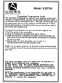
Model AS9233ST
OWNER’S MANUAL
Remote Start Alarm Keyless Entry
Upgrade System
Congratulations on your purchase of this automotive Remote Start / Alarm Keyless Entry
Upgrade System. This system is a state - of - the - art system is designed to arm and disarm
when it receives a lock or unlock command from your existing Factory Keyless Entry
Transmitter. Taking a few moments to read this manual will help to ensure that your vehicle
is protected at all times.
NOTE:
The system has the ability to beep the vehicle's horn, sound a siren, or both. Where a beep
or chirp is mentioned, consider either or both may sound.
Also All functions of the system will be controlled by the factory transmitter, including the start
sequence however for optimum range, it is suggested that the one button transmitter supplied
be used for starting, and unlocking while running under control of the the remote start.
ARMING THE SYSTEM: ( ACTIVE )
1. Turn the ignition key off, exit the vehicle, and close all doors.
2. Press and release the Lock button on the keychain transmitter.
3. The siren and or horn will beep one time, the parking lamps will flash one time,
and the LED found on the glass mounted receiver will begin to slowly flash, indicating that
the system is ARMED.
If the siren/horn sounds 3 chirps, then you have left a door, trunk, or hood lid ajar.
Simply close the opened entry point to provide full protection. If the siren "chirped"
three times, sometime after arming, the exclusive delayed dome light learn circuit
has been programmed and the system detected a open entry point after the
learned delay expired. Again, closing the hood, trunk, or doors will correct the
problem and you do not need to disarm the system to make the correction. If the
siren/horn did not sound when arming, then the chirps have been turned off, and
you should refer to the section titled “ ELIMINATING THE ARM / DISARM CHIRPS “
in this manual.
4. Any time the door lock switch in the vehicle is used to lock the doors while
the ignition key is turned off, the system will immediately arm. To lock the doors
after entering the vehicle, make sure the ignition key is switched on first.
Turning the ignition key on first will stop the system from arming.
ARMING THE SYSTEM: ( PASSIVE )
1. Turn the ignition key off, exit the vehicle, and close all doors.
2. The LED will begin to flash rapidly, indicating that the system
is automatically ( passively ) arming. As an added convenience, the 30
second automatic passive arming will not begin until all doors are closed,
allowing passengers to exit the vehicle at their convenience.
3. In 30 seconds, you will hear a single short chip from the siren, and the vehicle’s
parking lamps will flash one time, indicating that the system has ARMED. At
this time, the dash mounted PRLED will begin to flash slowly, providing a
visual indication that the system is fully armed.
4. It is possible to program the system, that when the alarm is allowed to
automatically passive arm, there will be a 15 second delay after a door is
opened before the alarm will sound. However, if the system is programmed
for instant trigger there will be no delay. Check with your installer for the setting
of this feature.
IMPORTANT! When the system is programmed for passive arming, the system
will always arm, even when the keychain transmitter has not been used to
lock the doors.
When you leave the vehicle, and a door has been left opened, the system will arm
after 10 minutes. If you plan to vacuum the car, or if service work is being
performed, either leave the key in the ignition and switched to the on position,
or put the system into valet mode. If you do not do this, the system will arm in
10 minutes, and you may inadvertently trip the alarm.
PROTECTION WHILE THE SYSTEM IS ARMED :
1. Opening any door, hood, or trunk will cause the alarm to immediately sound.
The alarm will continue to sound for 30 seconds, then stop and
automatically rearm the vehicle. If the potential thief left a door opened, the
alarm will sound for three more 30 second cycles, then re - arm and ignore the
opened door zone.
2. Whenever the system is armed, the on glass receiver's LED indicator will
slowly flash. This serves as a visual deterrent to the potential thief. The LED
is a very low current bulb, and will not cause the vehicle’s battery to drain, even
when the vehicle is left unattended for extended periods.
3. Whenever the system is triggered, the vehicle’s parking lights will flash for the
30 second alarm cycle, attracting added visual attention to the vehicle.
4. Whenever the system is armed, the vehicle’s starter will be disabled. The
vehicle will not start.
DISARMING THE SYSTEM :
1. As you approach the vehicle, press and release the unlock button on the
keychain transmitter.
2. The siren and or horn will beep two times, the parking lamps will flash two
times, and the on glass receiver's LED will turn off, indicating that the
system is DISARMED. If the optional entry illumination feature has been
installed, the vehicle’s interior lights will turn on for 30 seconds, or until the
ignition key is turned on.
NOTE: If your system has been programmed for “ passive arming “, then it will
begin to re-arm immediately after disarming. This is indicated by a
rapid flashing of the on glass receiver's LED. Opening one of the
vehicle’s doors will suspend the passive arming process until all doors
have been closed, or until the ignition key has been turned on.
INTRUSION WARNING SIGNALS :
The system will inform you if an intrusion attempt has occurred while you were away from
the vehicle. If an intrusion attempt has occurred, the siren and or horn will beep four times
when the system is disarmed. The vehicle’s parking lights will also flash three times to indicate
an intrusion has occurred.
Enter the vehicle and observe the on glass receiver's LED for further information.
1. If the LED is flashing one time...pause...one time...pause...etc., then an
intrusion attempt was made to a voltage sensing, light activated entry point, or
to an optional sensor that has been connected to zone 1.
2. If the LED is flashing two times...pause...two times...pause...etc., then an
intrusion attempt was made to the hood or trunk, or to an optional sensor that
has been connected to zone 2.
3. If the PRLED is flashing three times...pause...three times...pause...etc., then an
intrusion attempt was made through one of the vehicle’s doors.
These intrusion warning indicators are stored in the system’s memory, and will only be erased
when the ignition key is turned to the “ on “ position.
OPERATING THE EMERGENCY PANIC:
The buttons on your keychain transmitter will allow you to immediately activate the alarm in
emergency situations. To use the remote panic switch;
1. Press the unlock, then lock, then unlock buttons on your keychain transmitter
Page 2
within 3 seconds. The alarm will immediately sound, and continue to sound for
30 seconds.
2. To stop the alarm before the 30 second cycle has expired, simply press
and release the unlock button on your keychain transmitter.
NOTE: If the factory system has a panic mode, it is suggested that the factory panic feature
be used instead of the PRO9233ST to prevent any potiential problem of turning off the panic
mode.
USING THE VALET SWITCH :
The valet switch allows you to temporarily bypass all alarm functions, eliminating the need
to hand your transmitter to parking attendants or garage mechanics. When the system is in
valet mode, all alarm functions are bypassed, however the remote panic feature and
remote door locks will remain operational. To use the valet mode, the system must first be
disarmed either by using your keychain transmitter, or by overriding the system as
explained in the Manual Override Section of this manual.
TO ENTER THE VALET MODE:
1. Disarm the unit by use of the factory transmitter or by use of the manual override
sequence.
2. Turn the ignition switch to the “On” position.
3. Press and hold the pushbutton switch found on the glass mounted receiver assembly
for 5 seconds, until the LED turns on, indicating valet mode has been successfully
entered.
TO EXIT VALET:
With the ignition switch in the on position, press and release the pushbutton switch one time
. The LED turns off indicating the valet mode has successfully been exited.
MANUALLY OVERRIDING YOUR SYSTEM:
USING SIMPLE VALET SWITCH MANUAL OVERRIDE
If your factory transmitter is lost, broken, or otherwise rendered inoperable your Security
System can be disarmed without the use of the keychain transmitter. This is necessary,
since you will need the ability to operate your vehicle if the transmitter is lost or its battery
fails. If your system has been selected for Valet Switch manual override as indicated on the
last page of this manual, to override the alarm system;
1. Open the vehicle door. The alarm will sound.
2. Turn the ignition key to the on position.
3. Within 5 seconds, press and hold the valet pushbutton switch found on the glass
mounted receiver.
The alarm system will stop sounding and enter the (bypassed) mode. You can now start
and operate the vehicle normally.
Typically this override mode is used only if the transmitter has become inoperative.
USING CUSTOM CODE MANUAL OVERRIDE:
If your factory transmitter is lost, broken, or otherwise rendered inoperable, your system
can be overridden allowing operation of the vehicle. The manual override code is preprogrammed at the factory to 11. This code can be changed by the operator to a more
familiar two digit number. Once you’ve become familiar with the system’s operation and
override procedure, we suggest you change the code for added security.
NOTE: The override procedure below describes use, assuming that the factory
preset code has not been changed and is still set to the factory default 11.
The on glass receiver's LED valet/override push button switch is used to enter the
tenths and units digits, pressing and releasing this button one time for each
digit required.
If your system has been selected for Custom Code manual override as indicated on the last
page of this manual, to bypass the alarm system; with a code of 11, follow the sequence
listed below:
1. The LED is flashing indicating the unit is armed, enter the vehicle, the siren
will sound, turn the ignition switch to the “on” position.
Page 3
2. Within 10 seconds begin to enter tenths digit of override code. (In this example the code is 11, so press and release the push-button switch found on the glass
mounted receiver assembly one time).
3. Within 10 seconds of entering the last tenths digit, turn ignition “off then on”.
4. Within 10 seconds of turning the ignition switch on, begin to enter units digit
of override code. (In this example the code is 11, so press and release
the push-button switch found on the glass mounted receiver assembly one time).
5. Within 5 seconds after the last units digit is entered, turn the ignition switch
off, then on, and start your vehicle.
If the manual override code is entered properly, the unit stops sounding, the LED turns off,
indicating a successful override. The system is now disarmed and you can start and
operate your vehicle. The unit will allow three attempts to disarm via the manual override
sequence. If the code is not successfully entered within the three attempts, disarming with
the manual override switch will be locked for 10 minutes.
In many cases, to increase the security of your system, you may elect to change the manual
override code to a number that is more familiar to you, or simply to have a different code
than was pre-assigned from the factory. To Change the pre-assigned override code follow
the steps outlined below.
It is advised you read both sections under the headings “Programming Your Custom Override Code” and, “Custom Code Programming Example”, To completely understand the procedure before beginning:
Programming Your Custom Override Code:
Unlike override switches easily found, and defeated, this system allows the consumer to program a personal override code, offering a higher level of security. The system
comes from the factory with a pre-programmed override code of 11. To change this default
override code, do the following:
1. Disarm the system by use of the transmitter, or by use of the emergency
override sequence. Turn the ignition switch to the on position.
2. Within 10 seconds, press and release the push-button switch found on the receiver
assembly 3 times.
3. Within 10 seconds turn the ignition switch off, on, off, on, off, on.
(The siren or horn will beep and the lights will flash one time.)
4. Within 10 seconds, begin to enter your chosen 10ths digit by pressing
and releasing the push-button switch from 1 up to 9 times.
5. Within 10 seconds of the last entered 10ths digit, turn the ignition switch off then
on.
6. Within 10 seconds, begin to enter your chosen units digit by pressing
and releasing the push-button switch from 1 up to 9 times.
7. Finish by turning the ignition switch to the off position.
If the new code was accepted, the unit will report back the newly entered code, by flashing
the LED, first indicating the 10ths digit, pause and then the units digit. The unit will report the
new code three times with a one second pause between each code, then the system will
begin arming. If the LED flash pattern reports the previously stored code, the new code
was not entered correctly. Please repeat steps 1 through 7 above considering the following.
NOTE: Acceptable digits 10ths or units are 1 through 9. The unit will not recognize
a 0 (Zero), or no digit entered in any place, units or tenths.
NOTE: If 15 seconds of inactivity expire, or if the ignition switch is turned off for
more then 5 seconds during any of the above steps, the unit will revert back
to the last successfully stored code.
Custom Code Programming Example:
To Change the code from the factory pre-assigned code of 11 to “52” you
would do the following:
1. Disarm the system by use of the transmitter, or by use of the emergency
override sequence.
Page 4
2. Turn the ignition switch to the on position.
3. Within 10 seconds, press and release the push-button switch found on the receiver
assembly 3 times.
4. Within 10 seconds turn the ignition switch off, on, off, on, off, on.
(The siren or horn will beep and the lights will flash one time.)
5. Within 10 seconds, begin to press and release the push-button switch to set the tenths
digit.
(As per the example, press and release 5 times to set the tenths digit to 5)
6. Within 10 seconds of the last press of the push-button, turn the ignition switch
off then on.
7. Within 10 seconds, begin to press and release the push-button switch to set the units
digit.
(As per the example, press and release 2 times to set the units digit to 2).
8. Turn the ignition switch to the off position. Immediately observe the LED
flash pattern.
You will note the LED flashing five times, pause, and then flash two times, pause. This
pattern will be repeated three times indicating the new code (52) has been accepted and
stored in memory.
NOTE: If after step 7, the LED flashes a code other than what was just entered,
this indicates that the code has not been changed. You will have to repeat
steps 1 through 7 above being certain to note the following:
Acceptable digits 10ths or units are 1 through 9. The unit will not recognize a 0 (Zero), or no digit entered in any place, units or tenths.
NOTE: If 15 seconds of inactivity expire, or if the ignition switch is turned off for
more then 5 seconds during any of the above steps, the unit will revert back
to the last successfully stored code.
OPTIONAL IGNITION LOCK/UNLOCK FEATURE :
If your existing factory installed keyless entry system did not include an ignition on/off door
lock and unlock feature, this feature can be activated from this upgrade system. When this
accessory has been added, any time the ignition key is turned to the on position and all vehicle
doors are closed, the doors will lock in 4 seconds. Additionally, any time the ignition key is
turned to the off position, the doors will unlock.
ELIMINATING THE ARM / DISARM CHIRPS :
The normal arming and disarming confirmation chirps can easily be turned off using the valet
pushbutton switch found on the glass mounted receiver assembly. To do this;
1. Turn the ignition key on, and then off.
2. Within 10 seconds of turning the ignition key off, press and release the push-button
valet/override switch 3 times.
3. a. If, before proceeding with step 1, the chirps were on, then you will hear 2
chirps to indicate that the chirps have been turned off.
b. If, before proceeding with step 1, the chirps were off, then you will hear 1 chirp
to indicate that the chirps have been turned on.
4. Whenever power to the system has been disconnected ( for repair or service
to the vehicle ), the chirps will be activated when the power is re - connected.
To turn the chirps off, simply execute steps 1 through 3 above.
NOTE : Whenever the Arm/Disarm chirps are bypassed, the 3 chirp defective
zone and the 4 chirp intrusion indicator will continue to operate. This
feature will always warn you if a door was left ajar when arming, or the
vehicle was tampered with in your absence.
REMOTE STARTING THE VEHICLE
The System WILL NOT start the vehicle if any one of the following conditions exists:
1. The Vehicle Hood Is Opened.
2. The Gear Selector Is In Any Gear Other Then Park.
3. The Brake Is Depressed.
4. The glass mounted push-button safety control Is In The Remote Start By-Pass mode.
CAUTION! Be certain that the vehicle is outdoors before using this or any remote vehicle
Page 5
starting device. A running engine produces dangerous carbon monoxide fumes which can be
harmful or fatal if prolonged exposure occurs. DO NOT remote start the vehicle if the car is
garaged.
To Remote Start The Vehicle:
Press and release the button of your Remote Start transmitter two times in
succession to activate the remote start system. The vehicle will start
and remain running for the pre-programmed 5, 10, 15, 20, 45, or 60
minutes. As a visual indication, the parking lights will flash or turn on as preselected by your installation center at time of installation. You may also start
the vehicle with the factory transmitter by pressing lock, unlock, lock in
succession.
When you arrive at your car, unlock the vehicle by pressing and releasing
the unlock button of your factory keychain transmitter, or pressing and
holding for 3 seconds the start button of the single button start transmitter
supplied with this kit. Enter the vehicle and turn the ignition key to the on but
NOT START position.
NOTE: The system may have been configured to allow start by pressing the
transmitter start button once instead of twice. Please consult your installation center as to the configuration of your partictular system.
CAUTION! Do not turn the key to the start position. This will cause the starter
motor to engage with the already running engine which could result in damage.
Step on the brake pedal to disengage the remote start unit. The vehicle will
continue to run on it's own power.
NOTE: The engine will stop running before the expiration of the pre-programmed run timer if
you complete any of the following:
1. Pressing the button of your Remote Start transmitter two times in succession while running
under control of the remote start system will turn the vehicle off.
2. Depress the vehicles brake pedal.
3. Opening of the the hood.
4. Racing the RPM of the engine to above 4000.
NOTE: If the vehicle is running under control of the remote start unit, and the
transmitter button is operated a second two times in succession, the
vehicle will immediately turn off.
Also note, if this option is installed, as you approach the vehicle while running under control of
the remote start unit, the single button transmitter can be used to unlock the doors, simply
press and hold the unlock button until the doors unlock.
OPERATING ON AUTOMATIC START UP TIMER MODE
The system has the ability to automatically start the vehicle every 2 or 4 hours over a 48 hour
period. This feature is especially useful in cold climates where the only means to keep the
engine and engine fluids warm is to periodically start the engine.
CAUTION! Be certain that the vehicle is outdoors before using this or any remote vehicle
starting device. A running engine produces dangerous carbon monoxide fumes which
can be harmful or fatal if prolonged exposure occurs.
DO NOT remote start the vehicle if the car is garaged.
TO BEGIN THE AUTOMATIC START UP TIMER
1. Turn the ignition key on then off.
2. Within 10 seconds, activate the RF start command two times by pressing the
button of the keychain transmitter four times in succession.
The parking lights will flash 4 times indicating the timed start mode is activated.
The vehicle, on a 2 or 4 hour interval basis, will automatically start, run for the preprogrammed time (5,10, 15, or 20 minutes), and then shut off. This will continue for 48 hours.
NOTE: The automatic start up timer can also be initiated from the keychain
transmitter.
To do this:
1. Start the vehicle using the keychain transmitter by pressing and releasing the
remote start transmitter button two times in succession. (The vehicle will start)
Page 6
2. Shut off the vehicle using the keychain transmitter by pressing and releasing
the remote start transmitter button a second two times in succession.
3. Within 10 seconds of step 2, activate the RF start command two times. In other
words, press and release the transmitter button 4 times in succession.
The parking lights will flash 4 times indicating the timed start mode is activated.
CANCELING THE AUTOMATIC START UP TIMER
To cancel the automatic start up timer do one of the following;
1. Start the vehicle manually with the use of the ignition key and depress the brake pedal.
2. Remote start the vehicle using your keychain RF transmitter.
And then shut off the vehicle using the keychain RF transmitter.
On Glass Mounted Push-Button SAFETY CONTROL SWITCH
The Push-Button LED safety control switch allows you to temporarily disable the remote
starting function of the system. This recommended whenever the vehicle is being serviced. To
place the system in the service mode:
1. With the system disarmed/unlocked, and the ignition switch off Press and Hold the pushbutton switch found on the glass mounted receiver assembly.
2. Turn the ignition switch on, off, on, off, on, off.
3. The LED begins to flash two short flashes followed by one long flashes and continues
this pattern until returned to normal mode of operation.
This puts the unit into the R/S Override mode indicating that the remote start is in the service
mode and will not start from RF or any other input Posse or otherwise.
To Exit R/S Override Mode
1. With the system disarmed, Press and Hold the push-button switch on.
2. Turn the ignition switch on, off, on, off, on, off.
3. The LED turns off indicating that the R/S unit is fully functional one again.
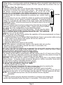
BATTERY REPLACEMENT
Your one button transmitter includes a battery #GP27a that will need to be
replaced from time to time. If you notice diminished range, or if the LED on
the transmitter lights dimly, the battery should be replaced. To do so:
1. Remove the 0 point philips head screw found at the lower portion in the rear of the case.
2. Carefully separate the two transmitter case halves.
3. Remove the battery noting the proper orientation/polarity of the battery. Properly dispose of
the discharged battery.
4. Install the new battery being certain to correctly arrange the proper polarity.
5. Carefully close the case halves, finish by re-install the screw removed in step 1.
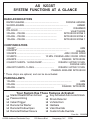
AS 9233ST
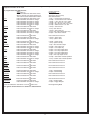
SYSTEM FUNCTIONS AT A GLANCE
DASH LED INDICATORS
RAPID FLASHING ..........................................................
PASSIVE ARMING
SLOW FLASHING ...........................................................................
ARMED
OFF ...........................................................................................
DISARMED
ON - SOLID ............................................................................
VALET MODE
3 FLASH ... PAUSE .....................................................
INTRUSION ZONE 3
2 FLASH ... PAUSE .....................................................
INTRUSION ZONE 2
1 FLASH ... PAUSE .....................................................
INTRUSION ZONE 1
CHIRP INDICATORS
1 CHIRP * ............................................................................................
ARM
2 CHIRPS* .....................................................................................
DISARM
3 CHIRPS ...................................................................
ARM / DOOR OPEN
3 CHIRPS .......................................
10 MIN. PASSIVE ARM / DOOR OPEN
4 CHIRPS .................................................................
DISARM / INTRUSION
2 SHORT CHIRPS - 1 LONG CHIRP.....................
DISARM / AFTER 10 MIN.
PASSIVE ARM
4 SHORT CHIRPS - 1 LONG ................................
DISARM / AFTER 10 MIN.
PASSIVE ARM AND INTRUSION
* These chirps are optional, and can be de-activated.
PARKING LAMPS
ARM
1 FLASH ..................................................................................................
DISARM
2 FLASH .........................................................................................
DISARM / INTRUSION
3 FLASH ...................................................................
Your System Has These Features Activated:
Starter Disable When Armed
Passive Arming
Instant Trigger
Remote Car Starter
Remote Window Open
Remote Window Closure
Key Activated Auto Lock/Unlock
Shock Detector
Vehicle Horn
Hardwire
Valet Override
Custom Code Override
Form No. 128-8604
© 2009 Audiovox Electronics Corp.
150 Marcus Blvd.
Hauppauge, N.Y. 11788
Model AS9233ST
Installation Manual
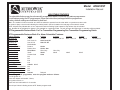
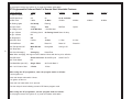
SELECTABLE FEATURES
The selectable features can be set manually as explained below, or with the RF feature programmer.
To set features using the RF programmer, follow the instructions packaged with the programmer.
Factory default settings are indicated by bold text.
Note : The method of manual override can either be selected to operate from the valet switch or operate as custom code.
Be certain to place a check mark indicating the method used in the box located on the last page of the owner's manual.
NOTE: Keyless Entry Models with no horn output will Flash the Parking Lights instead of chirp where chirp is indicated.
Also, No data will be indicated if a feature is not available for a particular model. The unit will enter the feature but no selection will be available.
RF Programmable Feature Bank 1 Is For Transmitter Programming See Transmitter Programming Guide.
RF Programmable Features Bank 2 Is Alarm Selectable Features:
1
Feature Selection
1 Chirp
1st DoorL/UL
1 Sec.
2nd Accy Lock
Auto Lock On
3rd Accy. UL
Auto UL On
4th Headlights
Not Available
5th Passive Locks
Passive
6th Pass/Act Arm
Passive Arm
7th Siren/Horn
Siren/Horn
8th Horn Chirp
10mS
9th O/R Method
Custom Code
10th 2 Step U/L
NA
11th Chp Del Tx
NA
12th Volts/HdWire
NA
13th Trigger Circuits
NA
14th L/UL Poll
120mS 80mS
15th Aux Channel 5 Select
NA
16th Aux Channel 6 Select
NA
17th Aux Channel 7 Select
NA
18th Trigger Delay
Instant
When using the RF programmer, enter the
Turn the ignition on.
Press and release valet switch 3 times;
turn ignition off then on.
Press and hold valet switch for 5 seconds.
2 Chirps
3.5 Sec.
Auto Lock Off
Auto UL Off
Active
Active Arm
Siren Only
16mS
Valet
3 Chirps
1 Sec L, Dbl. U/L
4 Chirps
Dbl L, 1 Sec UL
5 Chirps
Dbl L, Dbl UL
Horn Only
30mS
40mS
50mS
Delayed
program mode as follows:
Siren chirps 2 times indicating access to RF feature program mode.
6 Chirps
1 S l/350mS ul
Note: Where indicated, press transmitter lock button to change, the Factory Transmitter Lock button, Door Lock Switch, or the
supplied transmitter can be used.
To program these selectable features;
Action
Turn ignition on
Press and release the valet switch 3 times
Within 3 seconds, turn ignition Off Then On
This Action Accesses Feature Bank 2 Alarm
First
System Response
No response
1 Chirp - LED 1 flash
Short chirp, then long chirp
Selectable Features
Press
Press
Press
Press
Press
Press
and release the valet switch 1 time
transmitter lock button to change
transmitter lock button to change
transmitter lock button to change
transmitter lock button to change
transmitter lock button to change
or
Second
Press and release the valet switch
Press transmitter lock button to change
or
Third
Press and release the valet switch
Press transmitter lock button to change
Press transmitter lock button to change
or
Fourth
Press and release the valet switch
or
Fifth
Press and release the valet switch
Press transmitter lock button to change
or
Sixth
Press and release the valet switch
Press transmitter lock button to change
or
Seventh
Press and release the valet switch
Press transmitter lock button to change
Press transmitter lock button to change
or
Eighth
Press and release the valet switch
Press transmitter lock button to change
Press transmitter lock button to change
Press transmitter lock button to change
Press transmitter lock button to change
or
Ninth
Press and release the valet switch
Press transmitter lock button to change
or
Tenth
Press and release the valet switch
or
Eleventh
Press and release the valet switch
or
Twelfth
Press and release the valet switch
or
Thirteenth
Press and release the valet switch
or
Fourteenth
Press and release the valet switch
Press transmitter lock button to change
or
Fifteenth
Press and release the valet switch
or
Sixteenth
Press and release the valet switch
or
Seventeenth
Press and release the valet switch
or
Eighteenth
Press and release the valet switch
Press transmitter lock button to change
or
Press and release the valet switch or turn the ignition off to:
or
Turn ignition switch off then on to advance to feature Bank 3:
1 chirp = 1 second door lock & unlock
2 chirps = 3.5 second door lock & Unlock
3 chirps = 1 sec. lock, dbl 1 sec. unlock
4 chirps = dbl 1 sec lock, 1 sec unlock
5 chirps = dbl 1 sec lock, dbl 1 sec unlock
6 chirps = 350mS unlock. 1 sec lock
2 chirps = auto locks off
1 chirp = auto locks on
3 chirps = auto unlock off
1 chirp = auto unlock drivers door only
2 chirps = auto unlock all doors
Non Functional On This Unit
2 chirps = active locks
1 chirp = passive locks
2 chirps = active arming
1 chirp = passive arming
1 chirp = siren and horn output
2 chirps = siren output only
3 chirps = horn output only
2 chirps = horn chirp output 16mS
3 chirps = horn chirp output 30mS
4 chirps = horn chirp output 40mS
5 chirps = horn chirp output 50mS
1 chirp = horn chirp output 10 mS
2 chirps = valet switch override operation
1 chirp = custom code override operation
Non Functional On This Unit
Non Functional On This Unit
Non Functional On This Unit
Non Functional On This Unit
1 chirp = 120mS Polling
2 chirps = 80mS Polling
Non Functional On This Unit
Non Functional On This Unit
Non Functional On This Unit
1 chirp = Trigger Instant
2 chirps = Trigger Delayed
Exit Programming Mode
2
To exit program mode, turn ignition off, or press and release valet switch.
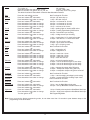
RF Programmable Features Bank 3 Is Remote Start Selectable Features:
Feature Selection
1 Chirp
3 Chirps
1st Defrost Output
NA
2nd RF Start Chirp
4 Chirps
5 Chirps
6 Chirps
Off
On
On & Carfinder
3rd Run Time
5 Mins
10 Mins
15 Mins
20 Mins
45 Mins
60 Mins
4th Parking Lights
On Steady
Flashing
5th Input Check
Voltage
Tach
DBI Tach
Hybrid
6th Voltage Level
>0.5V B4 Start
< 0.5V B4 Start
7th Ign. 2 Select
Off During Crank
On During Crank Same As Accy.
8th Ign. 3 Select
NA
9th Diagnostics
Off
On
10th Crank Time
0.8 Sec
1.0 Sec
1.5 Sec
2.0 Sec
11th Gas/Diesel
Gas
Diesel 10
Diesel 15
Diesel 20
12th Transponder O/P
While R/S On
During Start
Until Ign. Off
13th Temp Start
NA
14th Crank Averaging
Averaging
3
2 Chirps
Preset Time
Note: When averaging, the engine must be started 4 times with the key to be effective.
15th R/S Shock
Shunt Until Clear Shunt R/S Cycle
16th Turbo Select
NA
17th Black/Blue (Aux O/P)
Single Pulse
As Feat #1 Bank 2
18th 1 or 2 Pulse to Start
2 Pulse
1 Pulse
Shunt From Tx
When using the RF programmer, enter the program mode as follows:
Turn the ignition on.
Press and release valet switch 3 times.
Turn ignition off then on.
Press and hold valet switch for 5 seconds.
The siren chirps 2 times indicating access to RF feature program mode.
When using the RF programmer, exit the program mode as follows:
To exit program mode, turn ignition off, or press and release valet switch.
Action
System Response
Turn ignition on
No response
Press and release the valet switch 3 times
1 Chirp - LED 1 flash
Within 3 seconds, turn ignition Off, On, Off, On
Short chirp, then 2 long chirps
This Action Accesses Feature Bank 3 Remote Start Selectable Features
First
Press the valet switch one time
or
Press and release the valet switch
Press transmitter Lock button to change
or
Press and release the valet switch
Press transmitter Lock button to change
Press transmitter Lock button to change
Press transmitter Lock button to change
or
Press and release the valet switch
Press transmitter Lock button to change
or
Press and release the valet switch
Press transmitter Lock button to change
or
Press and release the valet switch
Press transmitter Lock button to change
or
Press and release the valet switch
Press transmitter Lock button to change
Press transmitter Lock button to change
or
Press and release the valet switch
or
Press and release the valet switch
Press transmitter Lock button to change
or
Press and release the valet switch
Press transmitter Lock button to change
Press transmitter Lock button to change
Press transmitter Lock button to change
or
Press and release the valet switch
Press transmitter Lock button to change
Press transmitter Lock button to change
Press transmitter Lock button to change
or
Press and release the valet switch
Press transmitter Lock button to change
Press transmitter Lock button to change
or
Press and release the valet switch
or
Press and release the valet switch
Press transmitter Lock button to change
Second
Third
Fourth
Fifth
Sixth
Seventh
Eighth
Ninth
Tenth
Eleventh
Twelfth
Thirteenth
Fourteenth
Non Functional On This Unit
2 chirps = RF start chirp on
1 chirp = RF start chirp off
2 chirps = run time set for 10 mins
3 chirps = run time set fro 15 mins
4 chirps = run time set for 20 mins
1 chirp = run time set for 5 mins
1 chirp = parking lights on steady w/RS active
2 chirps = parking lights flashing w/RS active
2 chirps = tachometer input checking
1 chirp = voltage sense input checking
1 chirp = greater than 0.5 V check before start
2 chirps = less than 0.5 V check before start
2 chirps = ign 2 on during crank
3 chirps = ign 2 same as accessory
1 chirp = ign 2 off during crank
Non Functional On This Unit
1 chirp = diagnostics off
2 chirps = diagnostics on
Seventeenth
Eighteenth
chirps = crank time 1.0 sec
chirps = crank time 1.5 sec
chirps = crank time 2.0 sec
chirp = crank time 0.8 sec
1
2
3
4
chirp = unit set for gasoline engine
chirps = unit set for diesel engine 10 sec delay
chirps = unit set for diesel engine 15 sec delay
chirps = unit set for diesel engine 20 sec delay
1 chirp = transponder output while R/S active
2 chirps = transponder output during start only
3 chirps = transponder output until ignition turned off
Non Functional On This Unit
1 chirp = crank averaging w/voltage input checking
2 chirps = preset crank time w/voltage input check
Non Functional On This Unit
Fifteenth
Sixteenth
2
3
4
1
or
Press and release the valet switch
or
Press and release the valet switch
Press transmitter Lock button to change
Press and release the valet switch
or
Press and release the valet switch
Press transmitter Lock button to change
or
Turn the ignition off to:
Non Functional On This Unit
1 chirp = aux o/p Black/Blue single pulse
2 chirps = aux o/p Black/Blue as alarm feature #1
1 chirp = Double pulse required on Blue/Black Start Input
2 chirps = single pulse required on Blue/Black Start Input
Exit Programming Mode
Note: Once you enter the feature programming mode, do not allow more than 15 seconds to pass between steps or the
programming will be terminated.
4
This Remote Start/Alarm System is designed to be used with Automatic Transmission Vehicles Only!
The unit provides a selectable ignition control that allows a number of selectable timed outputs for glow plug
pre-heat which may be required for certain diesel vehicles, (see selectable feature #9). If the diesel engine has
a instant fire, (no glow plug pre-heat system), feature #9 should remain in the default Gasoline mode setting.
For diesel applications, consult your dealer for the type of ignition system used in your particular vehicle.
Regardless of the vehicle, Gasoline or Diesel, for every installation, the vehicle MUST HAVE a Tach Signal
Input, and an Automatic Transmission.
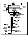
INSTALLATION OF THE MAJOR COMPONENTS:
CONTROL MODULE:
Select a mounting location inside the passenger compartment (up behind the dashboard). The mounting
location selected must be within 24" of the ignition switch wiring harness to allow connection of the 6 pin main
wiring harness.
Be certain that the chosen location will not interfere with proper operation of the vehicle. Avoid mounting the
module to or routing the wiring around the steering shaft/column, as the module or wiring may wrap around or
block the steering wheel preventing proper control of the vehicle. Secure the module in the chosen location
using cable ties or screws as necessary.
Do not mount the module in the engine compartment, as it is not waterproof.
OPTIONAL SIREN:
Select a location in the engine compartment that is not accessible from below the vehicle. The selected
location must be clear of hot or moving parts within the engine compartment. The siren must be pointed
downward to prevent water retention and the flared end must be pointed away from and out of the engine
compartment for maximum sound distribution. Before securing the siren, check behind your chosen location
to assure that the mounting screws will not penetrate any factory wiring or fluid lines. Secure the siren
mounting bracket using #8 self taping screws or by first using the mounting bracket as a template, scribe or
mark the mounting holes. Drill the marked holes using a 1/8" drill bit, then mount the siren using #8 sheet
metal screws.
HOOD AND OPTIONAL TRUNK PIN SWITCHES:
The pin switch included in this package is intended for protecting the hood area of the vehicle. In all cases, the
switch must be mounted to a grounded metal surface. When the pin switch is activated, (hood open), it will
supply a ground to the input wire activating the alarm. In addition, the hood switch is required for the safety
shut down of the remote start unit. If the vehicle is being worked on, this hood switch prevents the remote start
activation even if the RF command to start is issued. This switch must be installed in all applications.
Failure to do so may result in personal injury or property damage. Mount the switch in the hood
locations away from water drain paths. If necessary, the use of an L bracket may be used to move the switch
away from rain gutters or allow mounting to the firewall behind the hood seal. In both cases the switch must
be set up to allow the hood to depress the switch at least 1/4 inch when the hood closed, and fully extended
when the hood is opened. For direct mounting, a 1/4 inch hole must be drilled. Carefully check behind the
chosen location to insure the drill will not penetrate any existing factory wiring or fluid lines.
Drill a 1/4" hole in the desired location and thread the pin switch into it using a 7/16" nut driver or deep well
socket. If using the mounting bracket, first secure the bracket to the desired location and secure the pin
switch in the pre-threaded mounting bracket hole.
For Trunk areas a similar installation method may be used and an optional switch may be purchased from the
Audiovox Accessory Catalog.
THE RECEIVER/ANTENNA /PUSHBUTTON/LED ASSEMBLY:
The Superheterodyne Receiver Antenna Assembly provided with this unit allows routing from below the dash
board for maximum operating range. Choose a location above the belt line (dashboard) of the vehicle for best
reception. Special considerations must be made for windshield glass as some newer vehicles utilize a metallic shielded window glass that will inhibit or restrict RF reception. In these vehicles, route the antenna toward
a rear window location for best reception. Secure the antenna with double stick tape provided. After securing
the antenna with tape, we advise also securing a section of the antenna cable to a fixed support. This will
prevent the antenna from dropping down in case the double stick tape is exposed to extreme heat which may
loosen its gummed surface. Route the 3 connectors toward the control module and plug the single blue wire's
white connector into the mating LED connector on the module, plug the single grey wire's blue connector into
the mating valet/override connector on the module and plug the 3 wire RF connector into the mating connector
of the module. Use caution not to pinch the cable as this will cause poor or no RF reception no LED, or the
inability to program the unit.
SHOCK SENSOR:
Select a centrally located, solid mounting surface for the shock sensor that will allow consistent operation
5
from all areas of the vehicle. The selected location must be within 18" of the control module to allow routing
and connecting of the 4 pin harness. Secure the shock sensor to the chosen location using two #8 self taping
sheet metal screws. The sensor can also be secured to an existing dash brace using cable tie straps.
Whichever mounting method is used be sure to allow access to the sensitivity adjustment potentiometer for
use later in the installation.
STARTER INHIBIT RELAY:
Select a mounting location within 12" of the ignition switch's low current start solenoid wire. Secure the relay
to an existing harness in the chosen location using a cable tie around the relay's wiring harness. Caution! Do
not wire tie the metal bracket to an existing wiring harness as vibration may cause chaffing and shorting
damaging the factory wiring. If an existing harness is not available then secure the relay's metal mounting tab
to an under dash metal brace with a #8 self taping sheet metal screw. Wire the relay as per the diagram found
later in this manual.
This system is to be used in vehicles with AUTOMATIC TRANSMISSIONS only! Although this combination
Alarm/Remote Start unit is a sophisticated system with many advanced features, IT MUST NOT be installed
into a vehicle with a manually operated transmission. Doing so may result in serious personal injury and
property damage.
I M P O R TA N T !
DO NOT PLUG THE SIX PIN MAIN POWER HARNESS OR THE MULTI PIN INPUT / OUTPUT HARNESS
INTO THE CONTROL MODULE UNTIL ALL CONNECTIONS TO THE VEHICLE HAVE BEEN MADE. AFTER
SELECTING YOUR TARGET WIRES AS DEFINED BELOW, DISCONNECT THE NEGATIVE BATTERY CABLE
FROM THE VEHICLE BATTERY PRIOR TO MAKING ANY CONNECTIONS.
WIRING THE 6 PIN MAIN POWER HARNESS:
Note: Do not remove the fuse holders from this wire harness. Fuses must be used and located as
close as possible to the power source for adequate protection of the vehicle.
Fused RED w/ WHITE TRACE WIRE: + 12 volt Battery 1 Source
Locate the vehicle battery wire(s) at the ignition switch. Verification: These wires will register voltage in all
positions of the ignition switch. Connect the Red w/White wire to the vehicle's battery wire. This wire provides
power for the control circuit as well as the ignition 1 and ignition 2 relays.
Fused RED WIRE: + 12 Volt Battery 2 Source
Locate the vehicle battery wire(s) at the ignition switch. Verification: These wires will register voltage in all
positions of the ignition switch. Connect the Red wire to the vehicle's battery wire. This wire provides power for
the start relay and the accessory relay.
I M P O R TA N T !
IT IS THE RESPONSIBILITY OF THE INSTALLING TECHNICIAN TO DETERMINE THE LOAD FACTOR OF
THE VEHICLE'S ELECTRICAL CIRCUITS WHEN THE VEHICLE IS RUNNING AND TO ADEQUATELY FUSE
THE TWO POWER WIRES BASED ON THAT LOAD. IF THE VEHICLE RUNNING UNDER LOAD WITH THE
AIR CONDITIONER, HEATER BLOWER MOTOR, AND ACCESSORIES EXCEEDS 24 AMPS CONTINUOUS, WE RECOMMEND THAT TWO FUSES BE USED IN COMBINATION ON EACH POWER WIRE AS
SHOWN BELOW. FOR ADDITIONAL INFORMATION, SEE TECH UPDATE ISSUED 9/30/96.
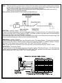
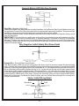
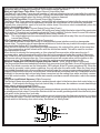
YELLOW WIRE: Starter Output
Careful consideration for the connection of this wire must be made to prevent the vehicle from
starting while in gear. Understanding the difference between a mechanical and an electrical Neutral Start Switch will allow you to properly identify the circuit and select the correct installation
method. In addition you will realize why the connection of the safety wire is required for all mechanical switch configurations.
Failure to make this connection properly can result in personal injury and property damage. In all installations
it is the responsibility of the installing technician to test the remote start unit and assure that the vehicle
cannot start via RF control in any gear selection other than park or neutral.
In both mechanical and electrical neutral start switch configurations, the connection of the Yellow wire will be
made to the low current start solenoid wire of the ignition switch harness. This wire will have +12 volts when
the ignition switch is turned to the start (crank) position only. This wire will have 0 volts in all other ignition
switch positions.
6
Note: This wire must be connected to the vehicle side of the starter cut relay (when used). For the electrical
neutral switch configuration, this connection must be made between the starter inhibit relay, (when
used) and the neutral safety switch as shown in the following diagram.
Failure to connect this wire to the ignition switch side of the neutral safety switch can result in
personal injury and property damage.
SEE NEUTRAL START SAFETY TEST FOR FURTHER DETAILS.
YELLOW START WIRE DETAIL
BLUE Wire: Ignition 1 Output
Connect this wire to the ignition 1 wire from the ignition switch. This wire will show +12 volts when the ignition
key is turned to the "ON" or "RUN" and the "START" or CRANK" positions, and will have 0 volts when the key
is turned to the "OFF" and "ACCESSORY" positions.
For Diesel Applications, this wire must be connected to the ignition circuit that powers the glow plugs if the
vehicle requires glow plug pre-heating. (See selectable feature #9)
GREEN Wire: Ignition 2 Output
Connect this wire to the ignition 2 wire from the ignition switch. This wire will show + 12 volts when the ignition
key is turned to the "ON" or "RUN" position and is some cases the "START" or CRANK" position. This wire
will show 0 volts when the key is turned to the "OFF" and "ACCESSORY" positions.
Note: See programming information concerning this wire to allow output during the "START" mode.
VIOLET Wire: Accessory Output
Connect this wire to the Accessory wire from the ignition switch. This wire will show + 12 volts when the
ignition switch is turned to the "ACCESSORY" or "ON" and "RUN" positions, and will show 0 volts when the
key is turned to the "OFF" and "START" or "CRANK" positions.
7
WIRING CONNECTIONS: Multi Pin Accessory Input/Output Harness
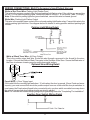
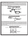
White w/ Red Trace Wire: Parking Light Flasher Feed
This wire is the common contact of the on board parking light flasher relay. If the vehicle you are working
on has +12 volt switched parking lights, connect this wire to a fused + 12 volt source. (Max. 15 Amps)
Note: If the vehicle's parking lights are ground switched, connect this wire to chassis ground.
White Wire: Parking Light Flasher Output
This wire is the normally open contact of the on board parking light flasher relay. Connect this wire to the
vehicle parking light feed wire. See diagram below for details on wiring positive switched parking light
circuits.
Parking Light Wiring Detail
White w/ Black Trace Wire: (+) Siren Output
This is the positive siren feed wire. Route this wire through a grommet in the firewall to the siren
location. Connect the White w/ Black Trace wire to the Red wire of the Siren. Secure the Black wire of
the Siren to a known chassis ground or solid clean metal surface.
Optional Siren Wiring Detail
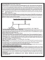
Purple Wire: (+) Door Trigger Input
If the vehicle's door courtesy light switches + 12 volts when the door is opened, (Some Fords and some
Imports), you must connect this wire to the positive output from one of the vehicle's door pin switches. In
most cases, the Purple wire will need to be connected to only one door switch no matter how many doors
the vehicle has as most door lighting circuits are wired in parallel.
Note: For vehicles with interior delay lighting see programming under title "Completing The Installation".
Positive Door Switch Wiring Detail
8
Dark Green Wire: (-) Instant Trigger Input
This is the instant on ground trigger input wire. This wire must be connected to the hood and trunk pin
switches where installed.
Note: This wire will be shunted when remote control channel 3 is accessed, (trunk release). This wire
will remain shunted all the while there is ground present and for 5 seconds after the ground is
removed. This allows the operator to open the trunk via the remote transmitter without having to
first disarm the alarm system. See below for wiring detail.
Hood Pin Switch Detail
Light Blue Wire: Ignition 3 Output
This wire provides a 300mA ground output that becomes active 3 seconds before the Remote Start Unit
initializes, and remains grounded while running plus an additional 4 seconds after the Remote Start Unit
turns off. In all of the applications described below, a relay will be required.
The Light Blue wire can be used to accommodate the following situations:
A. Shock Sensor By Pass:
If there is a Non Plug in Shock Sensor used with the alarm system and it is not shunted during the
Remote Start activation period, then vibration from the running vehicle can cause the alarm to trigger. In
this case, connect the Light Blue Wire to terminal #86 of a external relay. Connect terminal # 85 of the
relay to a fused + 12 volt battery source. Cut the shock sensor trigger wire and connect one end of the
cut wire to terminal #30 and the other end of the cut wire to terminal #87a. Just before the Remote Start
unit is activated, the relay contacts will open, preventing the shock sensor's operation until the Remote
Start unit shuts off.
B. Ignition 3 Output:
Some newer vehicles use a third ignition wire which is required to start and keep the vehicle's engine
running. If this is the case, connect the Light Blue wire to terminal #86 of an external relay. Connect
terminal # 30 & # 85 to a fused + 12 volt battery source rated for a minimum of 25 Amp. Connect
terminal # 87 to the third ignition wire in the vehicle.
C. GM VATS Key Override:
If the vehicle has the General Motors VATS system installed, you will need to bypass the system while
the vehicle is operating under the control of the Remote Start Unit. To do this;
1. Measure the resistance of the resistor pellet on the ignition key then select a resistor within 5% of
the key's value from the resistor pack supplied.
2. Locate the pair of VATS wires in the vehicle, usually a pair of thin gauge wires running from the
ignition switch to the VATS control module.
Note: These wires are typically White w/ Black trace and Violet w/ Yellow trace, however in later model
Cadillacs, they are run through an orange sleeve, and are either both Black, both Yellow, or both
White wires. Consult the factory service manual for additional information.
3. Connect the Light Blue Wire from the Remote Start Unit to terminal #86 of an external relay. Connect
terminal #85 of the relay to a fused + 12 volt battery source.
4. Cut (#1) wire (as shown), and connect the ignition switch side of the cut wire to terminal #87a of the
relay. Connect the other side of the (#1) wire to terminal #30.
5. Connect the previously selected resistor from terminal #87 to the second (#2) wire (as shown).
Note: The above information and following diagram is for the GM VATS system only. For GM PASS
LOCK System you will require the Audiovox AS-PASS II Module.
9
General Motors VATS By-Pass Diagram
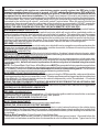
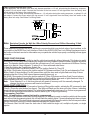
Grey Wire: Negative Inhibit Input
The Grey w/ Black Trace wire provides an instant shutdown for the Remote Start Control Module whenever
it is grounded. Connect the Grey trace wire to the hood pin switch previously installed. This wire must be
routed through a grommet in the firewall and connected to the hood pin switch.
If the factory switch is used, a diode assembly as shown below may be used to isolate the factory circuit
from the this circuit.
IMPORTANT! This connection is a safety wire and must be connected as shown and tested as specified.
Failure to do so may result in personal injury or property damage. See detail of wiring in the following
diagram. This wire may also be used if the vehicle brake light circuit switches ground to the brake lights.
An isolation diode must be used for ground switched brake light circuits and must be connected to the
output of the brake switch.
Grey Negative Inhibit Safety Shut Down Detail
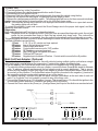
Orange Wire: Ground When Armed Output
This wire provides a 300 mA ground output when the alarm circuit is armed to control the starter inhibit
relay. Connect the Orange wire to terminal #86 (orange wire) of the relay provided. Connect terminal #85
(red wire) of the relay to an ignition wire in the vehicle that is +12 volts when the ignition switch is turned to
the on and start positions and off when the key is off. Locate and cut the low current start solenoid wire
found at the vehicles ignition switch harness. This wire will have + 12 volts when the ignition key is moved
to the start (crank) position and will have 0 volts in all other key positions. Connect one side of the cut wire
to terminal #87a ( Black wire) of the relay. Connect the other side of the cut wire to terminal #30 (White/
Black wire) of the relay. See below for detail of wiring, also see Yellow Start wire detail for connection to
vehicle considerations.
Starter Inhibit Wiring Detail
Black
White/Black
10
Brown w/ Black Trace Wire: Positive Inhibit Input
The Brown w/ Black Trace wire provides an instant shutdown for the Remote Start Control module whenever it gets + 12 volts. If the Brake lights switch in the vehicle switches + 12 volts to the brake light circuit,
connect the Brown w/ Black trace wire to the output side of the brake switch. This will allow the Remote
Start to shut down if an attempt is made to operate the vehicle without the key while running under the
control of the Remote Start. In most vehicles, in order to shift into gear, the brake pedal must be depressed. The brake input will in turn cause the remote start unit to shut off. See detail in the following
diagram for wiring the brake light circuit.
Brake Switch Positive Shutdown Detail
Black Wire: Chassis Ground Source
Connect the Black wire to a known vehicle ground source or to a solid clean metal part of the chassis. Be
certain to remove any paint or grease and secure this wire with a self taping screw and ring terminal.
Chassis Ground Connection Detail
Green w/ Orange Trace Wire: Tachometer Input Signal
This wire will continually monitor the engine's tach rate while the unit is under power of the Remote Start
module. This wire will be routed to the vehicle ECM tach input or through the firewall into the engine
compartment and connect to the negative side of the ignition coil. This Remote Start unit learns the tach
rate of the vehicle and in most cases will operate properly from one multi coil pack regardless of the number
of cylinders. If the vehicle has a single coil unit for each cylinder, it may be necessary to connect this wire
to more than one cylinder for proper tach reference. See multi coil wiring detail shown later in this manual
for additional information.
Note: For Hybrid mode, Bank 3 feature selection 5, this connection is not used, the unit will start the
vehicle and run the allotted time based on feature selection and crank duration.
Tachometer Input Wiring Detail
11
Green/Yellow Wire: Diesel Wait To Start Input
The Green/Yellow wire will connect to a diesel vehicles glow plug wire. When the unit receives a start command,
this wire must go to + 12 then to ground to allow the crank sequence to begin. When ignition #1 is activated by the
remote start unit, the glow plug circuit gets energized, (+ 12 volts), when the glow plug circuit of the vehicle drops
the + 12 volts, which effectively grounds the wait to start input, then 500mS later the starter will engage. This wire
can also be connected to the Glow Plug Bulb wire in the vehicle if this bulb wire gets + 12 volts when the ignition
comes on and drops low when the glow plug circuits temperature is reached. Be sure to fuse the wire with a 1 Amp
Fuse when connecting to a high current circuit such as a factory glow plug wire. The fuse should be installed as
close to the high current wire as possible. If you are installing this unit in a Gasoline vehicle, this wire is not used.
Note:
If the Glow Plug sense wire, Green/Yellow is connected, this wire will have priority over the setting of feature
Bank 3 Feature #11.
Brown Wire: Negative Door Trigger
If the vehicle's door courtesy light switches ground when the door is opened, (Most GMs and Imports), you
must connect this wire to the negative output from one of the vehicle's door pin switches. In most cases the
Brown wire will need to be connected to only one door switch no matter how many doors the vehicle has as
most door lighting circuits are wired in parallel.
NOTE: For vehicles with interior delay lighting see programming under title "Completing The Installation"
Negative Door Switch Wiring Detail
Dark Blue/Black Trace Wire: External Trigger Input
The Dark Blue/Black trace wire allows the remote start unit to be activated from an external source. The
intent of this wire is to allow the unit to be controlled from a "POSSE/CAR-LINK" paging system or similar
device. When this wire receives a ground pulse, the unit will start the vehicle. Connect this wire to a ground
pulsed output from the controlling circuit.
Black w/ White Trace Wire : 300 mA Horn Output
The black w/ white trace wire is provided to beep the vehicle’s horn. This is a transistorized low current
output, and should only be connected to the low current ground output from the vehicle’s horn switch.
If the vehicle uses a + 12 VDC horn switch, then connect the black w/ white trace wire to terminal 86 of the
AS 9256 relay ( or an equivalent 30 Amp automotive relay ), and connect relay terminal 85 to a fused + 12
VDC battery source. Connect relay terminal 87 to the vehicle’s horn switch output, and connect relay
terminal 30 to a fused + 12 VDC battery source.
YELLOW w/ BLACK Tracer Wire: + 12 Volt Alarm By - Pass Output
Note: You must disconnect the ignition input of the alarm from any other wire that it is presently connected
to in the vehicle.
This wire provides a + 12 Volt output when the ignition key is turned to the “ON” position, and 0 Volts when
the ignition key is “OFF” and when the vehicle is running under the control of the remote starter.
This wire should be connected to the ignition input of the alarm system.
The Yellow w/ Black wire output will allow you to remote start the vehicle while leaving the alarm armed, and
to lock/unlock the doors while running under control of the remote start unit.
UNDERSTANDING ARM & DISARM #1 AND #2:
Because of the complexities of the different factory installed Remote Keyless Entry Units on the market
today, this system uses two disarm and two arm inputs. Whether installing into a vehicle using a 2-step
unlock circuit, single step unlock circuit, or as a stand alone passive alarm, both disarm and arm wires must
be connected in all installations.
The arm and disarm functions of this system are learned during power up, by monitoring the resting state
of the factory wires when power is applied to the unit. Be certain all wires are connected to the vehicle before
applying power to the circuit to insure the system responds only during operation from the factory
transmitters.
5 PIN WHITE CONNECTOR: GREEN/BLACK, RED, GREEN, RED/BLACK, & BLUE FACTORY
KEYLESS INPUTS:
12
Note! When installing this system as a stand alone passive security system, the RED wire in this
connector must be connected to a rest at ground , + 12 VDC switched ignition source. RED w/BLACK,
GREEN & GREEN/BLACK wires must be connected to ground. The BLUE wire in this connector will not
be required for the stand alone installation. The Trigger Input, feature # 18 must be set for delay instead
of instant, to insure the consumer has time to get into the vehicle and turn the ignition on before the alarm triggers.
The Green/Black, Red, Green, and Red/Black wires of the 5 pin connector are polarity learning inputs to be
connected to the vehicle lock & unlock 1, and lock & unlock 2 control wires. When the control circuit is first
powered up, these wires will learn the resting state of the circuits they are connected to. DO NOT operate the
vehicle's door lock circuits, (switch or remote), while power is being applied to this upgrade alarm system.
WIRING THE ARM / DISARM INPUTS IN VEHICLES WITH REMOTE 2 STEP UNLOCK
The following represents the most common wiring routine in vehicles using the remote 2 step unlock feature.
GREEN/BLACK WIRE : ARM INPUT #2
Connect this wire to the vehicles door lock switch input wire, which will receive either a switched positive or
switched negative when the door lock switch is moved to the lock position. This wire will be used to compare
the two inputs Arm #1 & Arm #2. If both inputs are active at the same time, the vehicle will not arm. The intent
of this wire is to prevent the system from arming when the in vehicle door lock switch is used to lock the doors,
insuring only the transmitter arms the system. If you do not desire this feature or the customer prefers that the
door lock switch arm the system as well as the transmitter, connect this wire to chassis ground.
RED WIRE : DISARM INPUT #1
Connect this wire to the driver's door unlock motor wire, which will receive a negative or positive pulse when the
drivers door is unlocked with the remote transmitter, and the door switch, but does not receive a pulse when
all doors are unlocked using the remote transmitter.
GREEN WIRE : ARM INPUT #1
Connect this wire to the lock side of the door lock/unlock switch or, the driver's door lock motor leg wire, which
will receive a negative or positive pulse when the doors are locked using the door switch or the remote transmitter.
RED w/BLACK TRACE WIRE : DISARM INPUT #2
Connect this wire to the unlock side of the door lock/unlock switch or any passenger door unlock motor wire,
which will receive a negative or positive pulse when all doors are unlocked using the door panel switch or the
remote transmitter, but will not receive a pulse when the driver only door is unlocked using the remote
transmitter.
NOTE: The Green/Black, Red, Green, & Red/Black wires MUST be connected to their respective source before
powering up the module as these wire are polarity learn and will not function properly if connected after power
up. In addition, these wires if not used as indicated above must be connected to ground. This will insure
proper operation and prevent inadvertent arming and disarming unintentionally.
BLUE WIRE : TRUNK TRIGGER SHUNT INPUT
This wire will determine if the vehicle’s trunk has been opened using the OEM transmitter, and prevent the alarm
from triggering when the factory transmitter is used. This wire requires a positive trigger input and must be wired
to the switched + 12 volt trunk control wire from the vehicle's keyless entry unit or, the switched + 12 volt side
of the vehicle's trunk release solenoid.
WIRING THE ARM / DISARM INPUTS IN VEHICLES WHEN THE SYSTEM IS SET UP AS A STAND ALONE
PASSIVE (IGNITION CONTROL) ALARM SYSTEM
For this mode of operation, be certain to set selectable features # 6 for passive arm, feature #18 for trigger delay.
GREEN/BLACK & GREEN WIRE: ARM INPUTS
Connect these wires to chassis ground.
RED WIRE : DISARM INPUT #1
Connect this wire to an ignition source that has +12 volts when the ignition switch is turned to the on and start
positions and has 0 volts when the switch is in any other position.
RED w/BLACK TRACE WIRE: DISARM INPUT #2
Connect this wire to chassis ground.
BLUE: TRUNK SHUNT INPUT
This wire is not used for the stand alone passive alarm application.
WIRING THE 4 PIN AUXILIARY OUTPUT HARNESS
The auxiliary 4 pin connector provides low current outputs to control various functions in the vehicle during
different stages of the Remote Start unit's operation. Understanding these outputs and the time in which they
occur will allow you to determine if they are needed for the particular vehicle you are working on as well as how
to use them.
Black w Blue Trace Wire: Pulsed Ground Output Before Start
The Black w/ Blue Trace wire will provide a 1 second 300 mA pulsed ground output 1.5 second before the
remote start unit activates as well as when the transmitter is used to disarm the system. Typical use for this
13
output would be to disarm a factory theft deterrent system to prevent false triggering of the factory alarm when
the remote start unit engages or when the 785 is used to unlock the doors.
Black w/ Light Green Trace Wire: Pulsed Ground Output After Start
The Black w/ Light Green Trace wire will provide a 1 second mA pulsed ground output after the vehicle is
started under control of the remote start unit. Typically this wire will be used to re-lock the vehicle doors if the
doors unlock automatically when the factory anti-theft system is disarmed.
Black w/ Red Trace Wire: Pulsed Ground Output After Shutdown
The Black w/ Red Trace wire will provide a 1 second 300 mA pulsed ground output after the remote start unit
shuts down. This output will occur regardless of whether the circuit times out or is manually terminated.
Typically this output will be used to re-lock the vehicle doors if the doors unlock automatically when the
ignition circuit transitions to off.
Black w/ Yellow Trace Wire: Ground Output During Start (Crank)
The Black w/ Yellow Trace wire will provide a 300 mA ground output while the starter output of the remote start
unit is active. This output can be used to activate the Crank Low/Bulb Test wire found in some GM vehicles.
This wire is also referred to as the ECM wake up wire in some vehicles.
Note: The outputs above are low current outputs and must be used with a relay if the circuit's requirement
is more than 300mA.
2 Pin Transponder Control Output: (Yellow Connector)
This output is intended to allow the control of a transponder bypass interface module or transponder
bypass relay. The system also allows software selections to control the way in which this output operates,
see remote start feature # 10 for setting this output.
When the unit is selected for output during the start sequence, this output will be active at the same time
Ign. 3 becomes active, and will remain active until the vehicle has started. This will be used for one time
read transponder circuits.
When the unit is selected for transponder on, this output will become active at the same time ign. 3
becomes active, and will remain active all the time the unit is operational under the control of the remote
start. When the unit is selected for continuous and the vehicle is started via the Remote Start, this output
will become active at the same time ign. 3 becomes active and will remain active until the ignition in the
vehicle goes low. This will allow the unit to be used for continuous read transponders circuits.
Receiver Pushbutton LED/Valet/Program/Override Switch: (Blue, White & Black Connectors)
The Grey and the Blue wires loaded into individual 2 pin connectors, and the Black, Green & Red wires loaded
into the 3 pin black connector are the Valet enable, LED cathode, & the RF power ground and RX. When the
Grey wire is grounded, under certain conditions, the unit will enter the valet mode. When the Grey wire is
sequentially grounded under other conditions, the unit will enter the various program modes indicated on the
integral LED built into the receiver. Route the Blue, White and Black connectors from the Combination receiver
assembly to the remote start unit and plug these connectors into the mating blue, white, and black connectors of the control module. For valet, remote start override, and alarm override information, refer to the owners
manual.
2 Pin Door Lock/Unlock Harness: (White Connector)
The Red and Green wires will provide either a pulsed ground output to the factory door lock control relay, or a
pulsed + 12 volt output to the factory door lock control relay. In either case, the maximum current draw through
these outputs must not exceed 300mA.
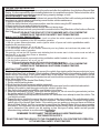
3 Wire Ground Switched Door Lock Circuits:
In this application, the Red wire of the door lock harness provides a ground pulse during the arming sequence,
or pulsed ground lock output. Connect the Red wire to the low current ground signal wire from the factory door
lock switch to the factory door lock relay.
The Green wire of the door lock harness provides a ground pulse during the disarming sequence, or pulsed
ground unlock output. Connect the Green wire to the low current ground signal wire from the factory door
unlock switch to the factory door unlock relay. See Below For Wiring Detail.
14
3 Wire Positive Switched Door Locks:
In this application, the Red wire of the door lock harness provides a + 12 volt pulse during the disarming sequence,
or pulsed 12 volt unlock output. Connect the Red wire to the low current 12 volt signal wire from the factory door
unlock switch to the factory door unlock relay.
The Green wire of the door lock harness provides a + 12 volt pulse during the arming sequence, or pulsed 12 volt
lock output. Connect the Green wire to the low current 12 volt signal wire from the factory door lock switch to the
factory door lock relay. See Below For Wiring Detail.
Note: Resistive Circuits, As Well As 4 Wire Polarity Reversal and 5 Wire Alternating 12 Volt
Door Lock Control Circuits
These applications require the use of additional components which may include relays, fixed resistors, or for
convenience, the DLRK Door Lock Interface. Refer to the AUDIOVOX Door Lock Wiring Supplement and or
the Audiovox fax back service for information on your particular vehicle for properly connecting to these types
of circuits.
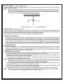
TIMED START PROGRAM:
The Remote Start unit has the ability to start the vehicle automatically at timed intervals. This feature is useful
in extremely cold climates where starting the engine is the only means to keep the battery charged and fluids
warm. The operator has the option to have the unit start every 2 or 4 hours for a maximum of 48 hours. Factory
preset is to start at 4 hour intervals. To select 2 or 4 hour automatic start timer:
1. Start By Holding the Push Button Switch On.
2. While Holding the Push Button Switch Turn The Ignition Switch On Then Off
3a) Within 10 seconds of turning the ignition switch off, Release and then Push On and release the Push
Button Switch 2 times holding it on the second time until the siren and or lights flash and chirp 2 times
indicating that the 2 Hour Start Interval has successfully been set. or
3b) Within 10 seconds of turning the ignition switch off, (Step 2) Release and then Push On and release
the Push Button Switch 4 times holding it on the fourth time until the siren and or lights flash and chirp 4
times indicating that the 4 Hour Start Interval has successfully been set.
Note: Once selected, 2 or 4, this timer interval will remain in memory until it is manually changed. To
change, the above sequence will have to be followed.
TIMED START OPERATION:
To begin the start timer, within 10 seconds of turning off the ignition switch, activate the RF command to start
2 times. (Press the start button four times). The lights will flash and the siren will chirp 4 times. Indicating
timed interval mode has been initiated. The vehicle will automatically start every 2 or 4 hours as programmed.
To cancel the timed start mode start the vehicle either by RF or by the ignition key.
Programming Tach Rate:
Note: All applications require that tach be programmed.
The unit will not operate unless tach is programmed. If an attempt is made to start the vehicle via the remote
start without first programming tach, the unit will flash the parking lights 7 times indicating tach has not been
learned and stored. If the tach rate is not properly programmed to the specific vehicle, the unit may not realize
that the vehicle is running in certain instances reengage the starter motor.
The Remote Start Unit will learn the tach rate of most vehicle's single coil, multiple coil packs, or single
injector.
15
To Learn Tach
1. Turn the ignition key to the On position.
2. Press and release the valet/program push button switch 3 times.
3. Immediately turn the ignition key Off.
4. Press and hold the valet/program push button switch, then start the vehicle using the key.
5. When the unit senses the tach signal, the parking lights will begin to flash.
6. Release the valet/program pushbutton switch. The parking lights will turn on for three seconds to indicate
that the learned tach signal is stored and the unit is out of the tach learn mode.
NOTE: If the unit fails to learn tach rate due to an improper tachometer connection or a poor tach source,
the parking lights will not flash.
To correct this situation, locate and connect the Green/Orange wire to the proper tach signal, and then
repeat the tach learn routine.
Diagnostics:
Enter selectable feature #7 and turn on as described above.
Note: Diagnostic mode is a temporary mode. Once you have accessed the diagnostic mode, the unit will
pause for two seconds then begin to flash the last stored shut down code. This code will be
displayed two times in succession, then the unit will automatically exit the diagnostic on mode.
The parking lights will flash a number of times indicating the reason for the last remote start shutdown. The
light flash indications are as follows:
1 Flash
5, 10, 15, or 20, minute run timer expired.
2 Flashes Low or No tach signal received.
3 Flashes Positive input shut down.
4 Flashes Control switch was moved to "Off" position.
5 Flashes RF Shutdown command received.
6 Flashes High RPM signal over speed shut down.
7 Flashes Tach has NOT learned.
8 Flashes Negative input shutdown 4 Flashes Control switch moved to the off position
Multi Coil Pack Adaptor: (Optional)
The multi coil pack adaptor is designed for use with vehicles having multiple ignition coils where a single
point tach signal is unavailable, or non responsive. Construct the adaptor as shown below.
To use the adaptor, the Green/Black wires must connect to the negative side of the ignition coil(s).
1. For vehicles utilizing independent coils per cylinder, connect the three Green/Black leads to alternate
coils. To achieve optimum performance the coil signals must be evenly distributed. This is accomplished by first mapping out the firing order of the engine in groups of as indicated below. Draw a circle
around any of the columns. The Green/Black wires should be connected to the negative (-) terminal of
the respective cylinder number which appears in any of the circles.
2. For vehicles utilizing 2 cylinder firing per coil pack, connect Green/Black to the tach side of each coil
pack. For 8 cylinder, four coil systems, connect to any of the three coils.
3. Connect the Yellow wire to a +12 volt ignition 1 source. This wire will have +12 volts with the ignition in the
on and start position and have 0 volts with the ignition in the off position.
4. Connect the Green wire to the (Green) or (Orange/Green) tach input of the Audiovox remote start unit.
16
TESTING YOUR INSTALLATION:
CAUTION!! The following procedure must be performed after the installation of an Audiovox Remote Start
Device. It is the responsibility of the installing technician to complete these tests. Failure to test the unit in
the following manner may result in personal injury, property damage, or both.
HOOD PIN SAFETY SHUT DOWN:
The intention of the hood pin safety shut down is to prevent the Remote Start unit from being activated while
a mechanic or vehicle owner is performing normal routine vehicle maintenance.
To test the integrity of this circuit:
1. With the drivers window in the down position, start the vehicle using the RF transmitter.
2. Reach inside the car and pull the hood release.
3. Raise the hood and confirm that the remote start unit shuts down.
If the unit fails this test, recheck your pin switch connection to the Gray/Black wire of the Audiovox Remote
Start Unit.
DO NOT RELEASE THIS VEHICLE TO THE CONSUMER UNTIL YOU CONFIRM THE
OPERATION OF THE HOOD PIN SAFETY SHUT DOWN FEATURE.
MANUAL SHUT DOWN / ENABLE CIRCUIT:
The intent of the manual shut down / enable circuit is to allow the vehicle operator to prevent operation of the
Remote Start Unit regardless of the RF transmitter operation.
1. With the system disarmed/unlocked, and the ignition switch off press and hold the pushbutton switch
located on the receiver unit on.
2. Turn the ignition switch on, off, on, off, on, off.
3. The LED begins to flash two short flashes followed by one long flashes and continues this pattern until
returned to normal mode of operation.
This puts the unit into the R/S Override mode indicating that the remote start is in the service mode and will not
start from RF or any other input Posse or otherwise.
To Exit R/S Override Mode
1. With the system disarmed, press and hold the pushbutton switch located on the receiver unit on.
2. Turn the ignition switch on, off, on, off, on, off.
3. The LED turns off indicating that the R/S unit is fully functional one again.
DO NOT RELEASE THIS VEHICLE TO THE CONSUMER UNTIL YOU CONFIRM THE
OPERATION OF THE MANUAL SHUT DOWN / ENABLE FEATURE.
NEUTRAL START SAFETY TEST:
The intent of the neutral start switch is to prevent the vehicle from starting while the gear selector is in any
position other than Park, or Neutral. When installing a Remote Start Device, it is imperative that the Yellow
Starter wire be connected to the ignition switch side of the Neutral Start Switch. Consideration for the
placement of a starter inhibit relay is important as well, and should be connected to the ignition switch side
of the Yellow Start Wire.
To test the integrity of the Neutral Start Safety Circuit:
1. Set the vehicle parking brake.
2. Block the drive wheels to prevent vehicle movement.
3. Temporarily disconnect the Brown/Black positive shut down wire from the vehicle's brake switch.
4. Sitting in the vehicle, start the engine using the vehicle's ignition key.
5. Step on the brake pedal and shift the gear selector into reverse.
6. Allow the transmission to shift. When you feel the engine pull, do not move the gear selector just turn
the ignition switch off. DO NOT attempt to remove the key.
7. Keeping the brake pedal depressed, activate the RF transmitter in an attempt to start the vehicle. The
car should not start.
8. Repeat the above test this time move the gear selector to the drive position. If the unit attempts to start,
failing this test, recheck your Yellow Wire's connection. This wire must be connected to the ignition
switch side of the Neutral Start Switch. If the vehicle you are working on does not have an Electrical
Neutral Safety Switch, it will be necessary to reconfigure the Remote Starts Wiring to accommodate
this vehicle. The information concerning the Mechanical Neutral Safety Switch provided below will help
you to determine if the vehicle you are working on has this type of safety switch and will provide
alternate wiring methods to accommodate this situation.
CAUTION!
REMEMBER TO RECONNECT THE BROWN/BLACK WIRE TEMPORARILY
DISCONNECTED IN STEP 3
DO NOT RELEASE THIS VEHICLE TO THE CONSUMER UNTIL YOU CONFIRM THE OPERATION
OF THE NEUTRAL SAFETY START FEATURE.
17
MECHANICAL NEUTRAL SAFETY SWITCH CONSIDERATIONS:
Mechanical neutral safety switch configurations differ slightly in that they do not offer the same level of safety
when installing a remote start device. Often when the ignition switch is turned off while the gear selector is in
any position other than park or neutral, the mechanical function will not allow the key to be turned to the start
position or be removed from the ignition cylinder. This configuration prevents mechanical operation while the
vehicle is in gear but offers no consideration for electrical operation. Because of this potential problem, this
installation requires the additional connection of a safety wire from the remote start device to the vehicle
Park/Neutral ECM Input or the vehicle key in sensor. This connection will prevent remote start operation if the
key is left in the ignition switch regardless of the gear selectors position.
KEY IN SENSOR CIRCUITS:
If the vehicle you are working on does not have or you cannot locate the ECM reference wire, there are two
alternatives available. Although not preferred, the vehicle Key In Sensor may be reconfigured to allow a
margin of safety and will prevent the vehicle with a Mechanical Neutral Start Switch from starting in gear.
AUDIOVOX ADVISES THAT YOU MAINTAIN THE FACTORY CIRCUIT WHENEVER POSSIBLE. The following two circuits may be used only if the above circuit is not available.
Note: When completing an installation using either of the following key in sensor circuits, if the operator
inserts the ignition key while the vehicle is running under the control of the Remote Start, the vehicle
will shut down. This must be explained to the operator as it is in contrast to the normal operation of
a vehicle utilizing an electrical neutral start switch and is inconsistent with the operators manual.
Additional information concerning Key In Sensor methods 1 & 2 are listed below and should be reviewed
before considering either alternative.
Method 1 will allow the safety required for the remote start unit and prevent the vehicle from starting while in
any gear other than Park or Neutral while the key is in the ignition cylinder however, if the key is left in the
ignition switch and the door is left opened, the added relay will be energized causing a 150mA drain on the
battery.
Method 2 will allow the safety required for the remote start unit and prevent the vehicle from starting while in
any gear other than Park or Neutral while the key is in the ignition cylinder however, the original factory key
in chime module will not alert the owner that the key has been left in the ignition switch. In addition, this may
also effect other warning tones such as the light on reminder.
These situations should be carefully considered before altering the vehicle's wiring and must be fully explained to the consumer. Circuits may be used only if the above circuit is not available.
METHOD 1
To connect to the key in sensor as shown in method 1:
A. Locate the control wire that connects the drivers door pin switch to the key in sensor switch.
B. Cut this wire and connect the ignition cylinder side to chassis ground.
C. Locate the key in sensor switch wire that connects the chime module to the ignition cylinder.
D. Cut this wire and connect the ignition cylinder side to terminal 30 of a P&B VF45F11 or equivalent relay.
E. Connect the cathode (striped) side of a 4002 series diode to this same wire, and connect the (non striped)
side to the negative shut down safety wire (Gray / Black) of the Audiovox Remote Start Unit.
F. Connect terminal 86 of the relay to a fused +12 volt constant battery source.
G. Connect terminal 87 of the relay to the Chime Module side of the previously cut wire in step D.
H. Connect terminal 85 of the relay to the Drivers Door side of the pin switch wire previously cut in step B.
NOTE: A second 4002 series diode may be required to maintain the integrity of the hood open, shut down
circuit. If this is the case, it must be installed as shown in the diagram above. The anode (Non Striped) side
must be connected to the Gray/Black wire of the Remote Start Unit. The cathode (Striped) side must be
connected to the hood pin switch. If the hood pin switch is also used for an alarm trigger input, be certain to use
the dual diode setup as shown in this installation guide under the heading hood switch.
18
METHOD 2
To connect to the key in sensor circuit as shown for method 2:
A. Locate the control wire that connects the drivers door pin switch to the key in sensor switch.
B. Cut this wire and connect the ignition cylinder side to chassis ground.
C. Locate the key in sensor switch wire that connects the chime module to the ignition cylinder.
D. Cut this wire and connect the ignition cylinder side to the Remote Start Negative Safety Shut down Wire
Gray/Black, using a 4002 series diode as shown above.
Note: A second 4002 series diode may be required to maintain the integrity of the hood open, shut down
circuit. If this is the case, it must be installed as shown in the diagram above. The anode (Non Striped) side
must be connected to the Gray/Black wire of the Remote Start Unit. The cathode (Striped) side must be
connected to the hood pin switch. If the hood pin switch is also used for an alarm trigger input, be certain to use the
dual diode setup as shown in this installation guide under the heading hood switch.
AFTER THE CONNECTION OF THE NEUTRAL START SAFETY WIRE AS INDICATED IN ANY OF
THE PREVIOUS ALTERNATE CONFIGURATIONS, THIS CIRCUIT MUST BE TESTED FOR OPERATION.
Retest by following the steps outlined in the NEUTRAL START SAFETY TEST shown in this manual.
4 Pin Upgrade Data Bus/Flash Logic Module:
If you are using an Audiovox Flash Logic module, it can be connected directly to the Alarm/Remote Start's
control module. Using the Blue 4 pin blue, red, black, & white harness and connect to the mating connector on
the Alarm/Remote Start control module. Wire the Flash Logic/Data Bus module to the vehicle as prescribed in
it's installation guide.
Note:
This unit has the ability to learn the dome light delay time, up to 60 seconds. If the vehicle has delay interior lights, and
you wish to avoid three chirp, defect zone, indication normally associated with this type of interior light, we suggest
you learn the interior light delay.
To learn the light delay, start with all doors closed:
1. Use the transmitter to Lock / Unlock / Lock / Unlock / Lock / Unlock / Lock, the system.
The LED turns on solid to confirm the system entered the learn mode.
2. Immediately open and close the door of the vehicle to initiate the dome delay.
The unit will monitor the door trigger input Positive, (Purple), and Negative, (Brown) when active.
When the dome light turns off, the unit will add 2 seconds then exit the learn mode.
3. The LED will begin flashing the Armed indication indicating the unit has exited the learn mode and is armed.
COMPLETING THE INSTALLATION:
After you have confirmed the operation of the Audiovox Remote Start Alarm system and tested all the safety features of the system:
1. Mount the control module up and behind the dash securing it in place with cable ties or screws. Be certain that the chosen
mounting location will not inhibit any of the controls of the vehicle.
2. Securely harness and tie all wiring up and away from all hot and moving parts that they may come in contact with
under the dash board or in the engine compartment areas.
CAUTION: Particularly avoid the area around the steering shaft and column, as wires can wrap around these mechanisms
and impair the safe operation of the vehicle.
3. Apply the Caution Labels supplied with this kit to a conspicuous area in the engine compartment. Make sure to clean the surface
before affixing the label.
4. Check the vehicle's wipers, lights, horn, etc.... to insure proper operation.
5. Replace all panels that were removed during installation, and retest the system.
6. Explain all activated features and safety systems associated with Remote Start Unit installed to the customer.
7. Place the Valet/Program/Override Switch Tag around the PRLED switch so the customer notes its location.
19
© 2009 Audiovox Electronics Corp., Hauppauge, N.Y. 11788
20
128-8605
~
Model S1BTXA
AUDIO'~OX
CORPORATION
Transmitter Programming Guide
This transmitter is designed for use with your upgrade remote start
unit and is programmed by using the remote start's program switch in
combination with the transmitter button. Although this transmitter can
be programmed into any of the Audiovox remote start and or alarm,
remote start systems, it will offer limited use and should be used for
the remote start upgrade only.
To program this transmitter into your remote start upgrade unit:
1) Turn the ignition to the on position
2) Press and release the programming switch 3 times
3) Press and hold, for 3 seconds, the button of the transmitter you
wish to add until the parking light flashes indicating the transmitter
has been learned.
4) Repeat step 3 for each transmitter up to a total of 4.
Turn the ignition off to exit the program mode.
NOTE: Do not allow more than 15 seconds to lapse between steps
or the program mode will be automatically exited and you will have to
start over.
This device complies with FCC Rules Part 15 Operation is
subiect to the following two conditions
(1) This device may not cause harmful interference and
(2) This device must accept any interference that may be
received, inclUding interference lhat may cause undesired
operation.
NOTE:The manufacturer is not responsible for any radio or
TV interference caused by unautl10rized modifications to
this eqUipment. Such motlifications could void the user's
authority to operate the equipment
ORDER FORM FOR TRAN5MlITER 51 BTXA
r=-'
III'
, ill
j Z
I
(=..i
~~
\n
Attention: Transmitter Ordering Department
Important: To help us expedite your order, please print all of the
information legibly and mail this form and your payment according
to the instructions below.
1)Name:
_
2) Address:
_
3) City:
.Zip Code:
State:
4 Telephone Number:(
)
_
_
5) Total Number Of Transmitters Required:~~_
Cost Per Transmitter is:
$65.00
X
MUltiply By Number Of Transmitters
6) Enter Total Amount Enclosed
(New York State Residents must include the appropriate sales tax)
7) Method of Payment:
o Mastercard
0 Visa D Check or Money Order (do not send cash)
Make Checks Payable To Audiovox Corporation
Credit Card Number:
---------------
Credit Card Expiration Date:
I
1__
8) Mail this form along with your payment to:
Transmitter Ordering Department
Audiovox Corporation 150 Marcus Blvd., Hauppauge N.Y.
11788
.•
.J~
.- Credit card purchasers can order additional or replacement
transmitters by phone. Simply dial 1 - 800 - 645 ~ 4994, and
follow the instructions from the operator interface
© 2009 Audiovox Electronics Corp., Hauppauge, N.Y. 11788 Form No. 128-8606
2
(LMA86060)
CAUTION!
THIS VEHICLE IS EQUIPPED WITH
A REMOTE STARTING DEVICE.
BE CERTAIN THIS UNIT IS DISABLED PRIOR TO
SERVICING VEHICLE OR POSSIBLE INJURY MAY RESULT:
132-4698
ATTENTION!
CE VEHICULE EST EQUIPE D'UN DISPOSITIF
DE DEMARRAGE A DISTANCE.
,
.
ASSUREZ-VOUS QUE CET APPAREIL EST DECONNECTE
•
•
AVANT DIEFFECTUER LA REVISION DE CE VEHICULE CAR
IL POURRAIT CAUSER DES BLESSURES. 132-4698
~d
noit'9tO,Q 91,irt9V
~ ®XO~ olau~ @
ZM3TZYZ YTIHU:l3Z
This product is covered by one or more of the following U.S. Patents; Other Patents pending.
373,319 375,909 376,116 377,459 383,895 407,034 580,160 5,132,660 5,157,375
5,193,141 5,245,694 5,315,285 5,323,140 5,334,969 5,349,931 5,357,560 5,381,128
5,412,371 5,467,070 5,469,141 5,469,151 5,506,568 5,532,670 5,534,845 5,563,576
5,563,600 5,572,185 5,602,535 5,614,883 5,617,819 5,646,591 5,650,774 5,656,868
5,656,997 5,673,017 5,712,638 5,783,988 5,783,989 5,798,711 5,805,056 5,819,568
5,828,316 5,838,255 5,850,173 5,850,174 5,855,050 5,872,519 5,898,391 5,900,806
5,905,431 5,907,195 5,914,667 5,945,936 5,952,933 5,990,786 6,028,372 6,028,505
6,040,636 6,043,734 6,087,996 6,093,979 6,140,914 6,184,779 6,218,740 6,259,169
6,285,296 6,288,635 6,317,034 6,452,483 6,452,484 6,462,648 6,573,838 6,697,719
6,700,4796,781,5076,828,901 6,982,631 7,030,7397,069,1277,095,314 7,102,515
7,135,9627,142,0977,191,0537,243,007 7,248,150 7,332,998 7,443,2857,463,135
7,483,783 7,519,400 7,532,959 7,616,099 7,646,285 7,653,463.
Form No.128-8874
(LGA88740)
Thank you for purchasing an Audiovol product. We pride ourselves on the quality and reliability of all our
electronic products but if you ever need service or have a question, our customer serv,ice staff stands ready to
help. Contact us at www.audiovol.com
."PURCHASE REGISTUTION:
Registering' On-line will allow us to contact you in the
unlikely event a safety notification is required Linder the Federal Consumer Safety Act.
L~
AUDIO''"O~
~ ELECTRONICS CORP.
Register Online at:
WWW.AUDIOVOX.COM
Click on Product Registration and Fill Out the Brief Questionnaire
(LGAAPS05)
Form No. 132-6751A
/
"'"
60 MONTH LIMITED WARRANTY
Applies to Pursuit Series Control Modules, Sirens, Sensors, and Relays.
AUDIOVOX Electronics Corporation (the Company) warrants to the original purchaser of this product that should this product, (other than
transmitters) under normal use and conditions, be proven defective in material or workmanship within 60 months of the date the unit was
originally installed, such defect(s) will be repaired or replaced with new or reconditioned product, (at the Company's option) without charge
for parts or repair labor. During the first 12 months of the warranty, there will be no charge for removing or reinstalling a product if performed
at a participating authorized Travelers Warranty Station. A transmitter is warranted for 12 months from the date of original purchase.
TRAVELER'S WARRANTY SERVICE 1-800-645-4994
Simply call toll free to our customer service office for reference to the authorized Warranty Station in your area and to obtain an Authorization number. No repairs or replacement will be made without a valid Authorization number.
To obtain repair or replacement within the terms of this Warranty, the product is to be delivered with proof of warranty coverage (e.g.dated
bill of sale), specification of defect(s), transportation prepaid, to an approved warranty station. This Warranty is not transferable.
This Warranty does not cover damage to the vehicle's electrical system or, except as above provided, costs incurred for removal or reinstallation ofthe product. This Warranty does not cover batteries, broken LCD or OLEO display screens, nor apply to any product or part thereof
which, in the opinion of the Company, has suffered or been damaged through alteration, improper installation, mishandling, misuse, abuse,
neglect, accident, or by removal or defacement of the factory serial number/bar code label(s).
This Warranty is in lieu of all other express warranties or liabilities. ANY IMPLIED WARRANTIES, INCLUDING ANY IMPLIED WARRANTY
OF MERCHANTABILITY, SHALL BE LIMITED TO THE DURATION OF THIS WRITTEN WARRANTY. ANY ACTION FOR BREACH OF ANY
WARRANTY HEREUNDER INCLUDINGANYIMPLIEDWARRANTYOF MERCHANTABILITYMUSTBEBROUGHTWITHINAPERIODOF72
MONTHS FROM THE DATE OF ORIGINAL PURCHASE. IN NO CASE SHALL THE COMPANY BE LIABLE FORANY CONSEQUENTIAL OR
INCIDENTAL DAMAGES FOR BREACH OF THIS OR ANY OTHER WARRANTY. No person or representative is authorized to assume for the
Company any liability other than expressed herein in connection with the sale of this product.
The company does not warrant that this product cannot be compromised or circumvented. THE EXTENT OF THE COMPANY'S LIABILITY
UNDER THIS WARRANTY IS LIMITED TO THE REPAIR OR REPLACEMENT PROVIDED ABOVE AND, IN NO EVENT, SHALL THE
COMPANY'S LIABILITY EXCEED THE PURCHASE PRICE PAID BY PURCHASER FOR THE PRODUCT WITHOUT INSTALLATION
LABOR.
Some states do not allow limitations on how long an implied warranty lasts or the exclusion or limitation of incidental or consequential damage
so the above limitations or exclusions may not apply to you. This Warranty gives you specific legal rights and you may also have other rights
which vary from state to ,state.
TRAVELER'S WARRANTY DEPARTMENT U.S.A.: Audiovox Electronics Corporation, 150 Marcus Blvd, Hauppauge, New York 11788
~
~
.
Form No.128-8446A~
~
{(
AA~ddF\A
\