1
Cisco Unity Express Voice-Mail and
Auto-Attendant CLI Administrator Guide
for 3.0 and Later Versions
First released: May 1, 2006
Last updated: November 13, 2013
Cisco Systems, Inc.
www.cisco.com
Cisco has more than 200 offices worldwide.
Addresses, phone numbers, and fax numbers
are listed on the Cisco website at
www.cisco.com/go/offices.
Text Part Number: OL-14010-09
THE SPECIFICATIONS AND INFORMATION REGARDING THE PRODUCTS IN THIS MANUAL ARE SUBJECT TO CHANGE WITHOUT NOTICE. ALL
STATEMENTS, INFORMATION, AND RECOMMENDATIONS IN THIS MANUAL ARE BELIEVED TO BE ACCURATE BUT ARE PRESENTED WITHOUT
WARRANTY OF ANY KIND, EXPRESS OR IMPLIED. USERS MUST TAKE FULL RESPONSIBILITY FOR THEIR APPLICATION OF ANY PRODUCTS.
THE SOFTWARE LICENSE AND LIMITED WARRANTY FOR THE ACCOMPANYING PRODUCT ARE SET FORTH IN THE INFORMATION PACKET THAT
SHIPPED WITH THE PRODUCT AND ARE INCORPORATED HEREIN BY THIS REFERENCE. IF YOU ARE UNABLE TO LOCATE THE SOFTWARE LICENSE
OR LIMITED WARRANTY, CONTACT YOUR CISCO REPRESENTATIVE FOR A COPY.
The Cisco implementation of TCP header compression is an adaptation of a program developed by the University of California, Berkeley (UCB) as part of UCB’s public
domain version of the UNIX operating system. All rights reserved. Copyright © 1981, Regents of the University of California.
NOTWITHSTANDING ANY OTHER WARRANTY HEREIN, ALL DOCUMENT FILES AND SOFTWARE OF THESE SUPPLIERS ARE PROVIDED “AS IS” WITH
ALL FAULTS. CISCO AND THE ABOVE-NAMED SUPPLIERS DISCLAIM ALL WARRANTIES, EXPRESSED OR IMPLIED, INCLUDING, WITHOUT
LIMITATION, THOSE OF MERCHANTABILITY, FITNESS FOR A PARTICULAR PURPOSE AND NONINFRINGEMENT OR ARISING FROM A COURSE OF
DEALING, USAGE, OR TRADE PRACTICE.
IN NO EVENT SHALL CISCO OR ITS SUPPLIERS BE LIABLE FOR ANY INDIRECT, SPECIAL, CONSEQUENTIAL, OR INCIDENTAL DAMAGES, INCLUDING,
WITHOUT LIMITATION, LOST PROFITS OR LOSS OR DAMAGE TO DATA ARISING OUT OF THE USE OR INABILITY TO USE THIS MANUAL, EVEN IF CISCO
OR ITS SUPPLIERS HAVE BEEN ADVISED OF THE POSSIBILITY OF SUCH DAMAGES.
Cisco and the Cisco logo are trademarks or registered trademarks of Cisco and/or its affiliates in the U.S. and other countries. To view a list of Cisco trademarks, go to this
URL: www.cisco.com/go/trademarks. Third-party trademarks mentioned are the property of their respective owners. The use of the word partner does not imply a partnership
relationship between Cisco and any other company. (1110R)
Any Internet Protocol (IP) addresses used in this document are not intended to be actual addresses. Any examples, command display output, and figures included in the
document are shown for illustrative purposes only. Any use of actual IP addresses in illustrative content is unintentional and coincidental.
Cisco Unity Express Voice-Mail and Auto-Attendant CLI Administrator Guide for 3.0 and Later Versions
© 2008-2013 Cisco Systems, Inc. All rights reserved.
CONTENTS
CHAPTER
1
Cisco Unity Express Features
1-1
Platforms and Cisco IOS Software Images
Supported Cisco Unified IP Phones
Cisco Unity Express Feature List
CHAPTER
2
1-1
1-1
1-2
Overview of Cisco Unity Express Voice Mail and Auto Attendant
Contents
2-1
2-1
Software Licenses and Factory-Set Limits
Administration Interfaces
User Subscriber Interfaces
2-1
2-1
2-2
Additional References 2-3
Obtaining Documentation, Obtaining Support, and Security Guidelines
Documents Related to Cisco Unity Express 2-3
Standards 2-4
MIBs 2-5
RFCs 2-5
Technical Assistance 2-5
CHAPTER
3
Entering and Exiting the Command Environment
EXEC and Configuration Modes
CHAPTER
4
Configuration Tasks
3-1
3-3
4-1
Configuring the System Using CLI Commands
Configuring the System Using the GUI
Configuration Tasks
Ongoing Tasks
As-Needed Tasks
3-1
3-1
Entering the Command Environment
Prerequisites 3-1
Exiting the Command Environment
2-3
4-1
4-1
4-1
4-10
4-10
Cisco Unity Express Voice-Mail and Auto-Attendant CLI Administrator Guide for 3.0 and Later Versions
OL-14010-09
iii
Contents
CHAPTER
5
Configuring System Components
5-1
Configuring SIP Call Control Parameters 5-2
Configuring the SIP Proxy Server Location for Cisco Unity Express 5-2
Required Data for This Procedure 5-2
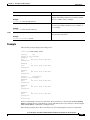
Examples 5-3
Configuring the Call Transfer Mode 5-4
Examples 5-5
Configuring DTMF Options 5-5
Examples 5-8
Configuring the MWI Notification Option 5-8
Outcall Notification (Not Available in Cisco SRST Mode) 5-9
Sub-Notify Notification 5-9
Unsolicited Notification 5-10
Examples 5-12
Configuring the MWI On and Off Extensions (Not Available in Cisco SRST Mode) 5-12
Prerequisites 5-12
Required Data for This Procedure 5-12
Configuring the Inclusion of Envelope Information in SIP MWI Notifications 5-13
Prerequisites 5-14
Configuring Centralized Cisco Unity Express 5-14
Defining a Cisco Unified CME Site (Site Provisioning) 5-16
Prerequisites 5-16
Deleting a Cisco Unified CME Site 5-18
Example 5-18
Configuring FAX Support for Centralized Cisco Unity Express 5-19
Prerequisites 5-19
Configuring NonSubscriber Distribution Lists for Centralized Cisco Unity Express 5-21
Configuring Cisco Unified CME SIP Options for RFC Compliance 5-21
Required Data for This Procedure 5-21
Example 5-22
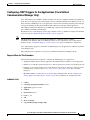
Configuring JTAPI Parameters (Cisco Unified Communications Manager Only)
Prerequisites 5-23
Required Data for This Procedure 5-23
Examples 5-26
Managing Scripts 5-26
Creating a Script File 5-26
Uploading a Script File 5-27
Displaying the List of Existing Scripts
Downloading a Script File 5-28
5-22
5-27
Cisco Unity Express Voice-Mail and Auto-Attendant CLI Administrator Guide for 3.0 and Later Versions
iv
OL-14010-09
Contents
Deleting a Script File
5-28
Managing Prompts 5-28
Recording a Prompt File 5-29
Uploading a Prompt File 5-29
Displaying Existing Prompt File lists
Downloading a Prompt File 5-30
Renaming a Prompt File 5-30
Deleting a Prompt File 5-30
Rerecording a Prompt File 5-31
5-29
Managing Applications 5-31
Creating and Modifying Applications 5-31
Required Data for This Procedure 5-31
Examples 5-34
Script Parameters for Applications 5-34
Deleting an Application 5-35
Required Data for This Procedure 5-35
Examples 5-36
Managing Triggers 5-38
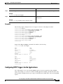
Configuring SIP Triggers for the Applications 5-39
Required Data for This Procedure 5-39
Examples 5-41
Wild Card Trigger Patterns 5-42
Configuring JTAPI Triggers for the Applications (Cisco Unified Communications Manager Only)
Required Data for This Procedure 5-43
Examples 5-45
Configuring HTTP Triggers for the Applications 5-45
Configuring Multiple Triggers for an Application 5-46
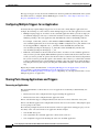
Sharing Ports Among Applications and Triggers 5-46
Accessing an Application 5-46
Sharing Ports Among Different Applications 5-47
5-43
Configuring Holiday Lists 5-47
Overview of Holidays 5-47
Year-Specific Holidays 5-48
Fixed Holidays 5-48
Using the Holiday Lists 5-48
Configuring Holiday Lists 5-49
Prerequisites 5-49
Configuring Year-Specific Holiday Lists 5-49
Configuring the Fixed Holiday List 5-49
Cisco Unity Express Voice-Mail and Auto-Attendant CLI Administrator Guide for 3.0 and Later Versions
OL-14010-09
v
Contents
Displaying the Holiday List 5-49
Prerequisites 5-49
Displaying All Holiday Lists 5-50
Displaying Holiday Lists for a Specific Year 5-50
Displaying Holiday Lists for a Specific Month 5-50
Deleting Holidays from the List 5-51
Prerequisites 5-51
Deleting a Year-Specific Holiday from the Holiday List 5-51
Deleting Year-Specific Holidays from a Specific Month 5-51
Deleting Year-Specific Holidays for a Specific Year 5-52
Deleting a Fixed Holiday from the Holiday List 5-52
Configuring Business Hours 5-52
Overview of Business-Hours Schedules 5-53
Using the Business-Hours Schedule 5-53
Creating a Business-Hours Schedule 5-53
Data Required for This Procedure 5-53
Examples 5-55
Modifying Business-Hours Schedules 5-55
Changing the Status of Open or Closed Hours
Displaying Business-Hours Schedules 5-57
Displaying a Specific Schedule 5-57
Displaying All Businesses Schedules 5-57
Deleting a Business-Hours Schedule 5-58
5-55
Configuring System-Wide Fax Parameters 5-58
Prerequisites 5-59
Required Data for This Procedure 5-59
Example 5-60
Configuring SMTP Parameters 5-60
Configuring an SMTP Server 5-61
Required Data for This Procedure 5-61
Example 5-62
Configuring SMTP Server Security 5-62
Configuring Historical Reporting 5-63
Configuring the Local Historical Reporting Database
Prerequisites 5-64
Examples 5-65
Configuring the Database Purge Schedule 5-66
Prerequisites 5-66
Examples 5-67
5-64
Cisco Unity Express Voice-Mail and Auto-Attendant CLI Administrator Guide for 3.0 and Later Versions
vi
OL-14010-09
Contents
Configuring the Database Capacity Threshold for a Purge 5-68
Prerequisites 5-68
Examples 5-69
Configuring the Database Threshold Capacity for Warning Notification
Prerequisites 5-69
Examples 5-70
Configuring the Purge Notification E-mail Addresses 5-71
Prerequisites 5-71
Examples 5-72
Manually Purging the Historical Reporting Database 5-72
Prerequisites 5-72
Examples 5-73
Exporting Historical Report Data to an External Server 5-74
Prerequisites 5-74
Examples 5-74
Assigning Historical Report Viewing Privileges to a Group 5-76
Prerequisites 5-76
Examples 5-77
5-69
Banner Support 5-77
Defining a Login Banner 5-78
Prerequisites 5-78
CHAPTER
6
Configuring Users and Groups
Prerequisites
6-1
6-1
Adding and Modifying a User 6-1
Required Data for This Procedure
Examples 6-5
Examples 6-6
Adding and Modifying a Group 6-7
Required Data for This Procedure
Examples 6-9
Examples 6-10
Configuring Privileges
CHAPTER
7
Configuring Voice Mail
6-2
6-7
6-11
7-1
Using the New Method of Sending Voice Mail
Configuring Triggers
7-1
7-1
Configuring the Voice-Mail Application 7-2
Sharing Ports Among Applications and Triggers
7-2
Cisco Unity Express Voice-Mail and Auto-Attendant CLI Administrator Guide for 3.0 and Later Versions
OL-14010-09
vii
Contents
Required Data for This Procedure
Example 7-4
7-2
Planning Mailbox Configuration 7-4
Types of Mailboxes 7-4
Mailbox Properties 7-5
Configuring Mailboxes 7-5
Prerequisites 7-5
Required Data for This Procedure 7-5
Examples 7-8
Configuring Multiple Greetings 7-10
Examples 7-12
Configuring PINless Mailbox Access 7-13
Prerequisites 7-13
The TUI and PINless Login 7-13
VoiceViewExpress and PINless Login 7-14
Unlocking a Voice Mailbox 7-16
Refreshing Message Waiting Indicators 7-16
Configuring an Announcement-Only Mailbox 7-17
Examples 7-18
Configuring Call Flow Customization 7-18
Examples 7-20
Configuring System-Wide Voice-Mail Parameters 7-20
Configuring System-Wide Voice-Mail Parameters for All Voice Mailboxes 7-23
Example 7-25
Configuring the Ability to Leave Multiple Voice Messages in the Same Session 7-27
Prerequisites 7-27
Configuring the Use of a Voice Mail Summary Prompt during Subscriber Login 7-28
Prerequisites 7-28
Configuring Message Properties (Envelope) Customization 7-29
Configuring Whether to Include Only Brief Message Properties 7-30
Prerequisites 7-30
Configuring Whether to Include Day-of-Week Message Properties 7-30
Configuring Default Addressing for Sending a Voice Message 7-31
Configuring Caller ID for Incoming Messages 7-32
Enabling Caller ID on the Local System 7-33
Disabling Caller ID on the Local System 7-33
Configuring Secure Messaging 7-33
Prerequisites 7-33
Overview 7-33
Configuring Global Secure Messaging Support 7-35
Cisco Unity Express Voice-Mail and Auto-Attendant CLI Administrator Guide for 3.0 and Later Versions
viii
OL-14010-09
Contents
Configuring Secure Messaging Support for Individual Mailboxes 7-35
Enabling Secure Messaging Support for a Remote Network Location 7-36
CHAPTER
8
Configuring Authentication, Authorization, and Accounting
Overview
8-1
8-1
Configuring the Accounting Server 8-2
Specifying AAA Accounting Settings
8-2
Configuring the Authentication Server 8-4
Specifying AAA Authentication Settings
8-4
Configuring the AAA Policy 8-5
Authentication Failover 8-6
Unreachable Failover 8-6
Example 8-6
Specifying the Policy that Controls the Behavior of Authentication and Authorization
Configuring Privileges 8-8
Configuration Example 8-13
Creating and Customizing Privileges
8-7
8-15
Configuring Accounting Event Logging 8-18
Configuring Accounting Event Logging 8-19
Configuring Console Authentication 8-21
Specifying Whether the Console Connection is Subject to Authentication
CHAPTER
9
Configuring the Administration via Telephone Application
Configuring Triggers
CHAPTER
10
8-21
9-1
9-1
Configuring Auto Attendants
10-1
Configuring and Managing the Auto-Attendant Application 10-1
Default Prompts 10-1
Triggers 10-1
Default Auto-Attendant Script aa.aef 10-2
Simple Auto-Attendant Script aasimple.aef 10-2
Configuring Other Auto-Attendant Parameters 10-3
Required Data for This Procedure 10-3
Examples 10-6
Configuring Auto-Attendant Prompts 10-6
Recording an Auto-Attendant Greeting or Prompt File 10-7
Uploading the Auto-Attendant Greeting or Prompt File 10-7
Customizing the Default Auto-Attendant Welcome Prompt 10-7
Cisco Unity Express Voice-Mail and Auto-Attendant CLI Administrator Guide for 3.0 and Later Versions
OL-14010-09
ix
Contents
Downloading an Auto-Attendant Greeting or Prompt File 10-8
Renaming an Auto-Attendant Greeting or Prompt File 10-8
Deleting an Auto-Attendant Greeting or Prompt File 10-8
Configuring Auto-Attendant Scripts 10-9
Creating an Auto-Attendant Script File 10-9
Uploading the Auto-Attendant Script File 10-9
Downloading an Auto-Attendant Script File 10-10
Deleting an Auto-Attendant Script File 10-10
CHAPTER
11
Configuring VoiceView Express
11-1
Overview of VoiceView Express 11-1
VoiceView Express Session Count 11-1
Configuring Cisco Unified Communications Manager for VoiceView Express 11-2
Configuring Cisco Unified Communications Manager Express for VoiceView Express
Session Termination 11-2
11-2
Configuring VoiceView Express 11-3
Prerequisites 11-3
Required Data for This Procedure 11-3
Examples 11-4
Configuring the Phone-Authentication Service 11-5
Prerequisites For Release 7.0 and Later 11-5
Prerequisites for Release 3.2 and Earlier 11-5
Example 11-6
Displaying and Terminating VoiceView Express Sessions
CHAPTER
12
Configuring Message Notification
Overview of Message Notification
Notification Profile 12-2
11-7
12-1
12-1
Message Notification Settings 12-2
System-Wide Message Notification Settings 12-2
Subscriber and Device-Specific Settings 12-5
Options and Settings 12-6
Sending and Receiving Message Notifications
Notifications to Phone Devices 12-7
Notifications to Numeric Pagers 12-8
Notifications to E-mail Inboxes 12-8
Notifications to Text Pagers 12-9
Configuring System-Wide Settings
12-7
12-9
Cisco Unity Express Voice-Mail and Auto-Attendant CLI Administrator Guide for 3.0 and Later Versions
x
OL-14010-09
Contents
Prerequisites 12-9
Required Data for This Procedure
Examples 12-12
12-9
Enabling Message Notification for a Subscriber or Group
12-12
Configuring Message Notification for Devices 12-13
Configuring Message Notification for Phone Devices 12-13
Prerequisites 12-13
Required Data for This Procedure 12-13
Examples 12-17
Configuring Message Notification for a Numeric Pager 12-17
Prerequisites 12-17
Required Data for This Procedure 12-17
Examples 12-21
Configuring Message Notification for E-mail 12-21
Prerequisites 12-21
Required Data for This Procedure 12-21
Examples 12-25
Configuring Message Notification for a Text Pager 12-26
Prerequisites 12-26
Required Data for This Procedure 12-26
Examples 12-29
Cascading Message Notification 12-29
Overview 12-29
Configurable Options 12-30
Limitations and Conditions 12-30
Configuring Cascading Message Notification 12-31
Prerequisites 12-31
Required Data for This Procedure 12-31
CHAPTER
13
Networking Cisco Unity Express
13-1
Overview of Cisco Unity Express Networking 13-1
Types of Remote Addressing 13-1
Blind Addressing 13-2
Spoken Name Confirmation for Remote Subscribers
Delivery Notifications 13-2
Non-Delivery Receipt (NDR) 13-2
Delayed Delivery Record (DDR) 13-2
Configuring Network Locations
Prerequisites 13-3
13-2
13-3
Cisco Unity Express Voice-Mail and Auto-Attendant CLI Administrator Guide for 3.0 and Later Versions
OL-14010-09
xi
Contents
Required Data for This Procedure
Examples 13-7
Disabling a Network Location
Examples 13-10
13-3
13-9
Downloading and Uploading Network Location Spoken Names
Required Data for This Procedure 13-11
Downloading the Location Spoken Name 13-11
Uploading the Location Spoken Name 13-11
13-10
Adding Remote Subscribers to the Local Directory 13-12
Configuring the Local Directory with Remote Subscribers 13-12
Configuration Mode 13-13
EXEC Mode 13-14
Examples 13-15
Displaying Remote Subscribers 13-16
Displaying All Remote Subscribers 13-16
Displaying a Specific Remote Subscriber 13-16
Deleting Remote Subscriber Information 13-16
Deleting an Extension Number 13-16
Deleting a Remote Subscriber Entry in Local Directory 13-17
Deleting a Remote Username 13-17
Downloading and Uploading Remote Subscriber Spoken Names
Required Data for This Procedure 13-18
Downloading the Remote Subscriber Spoken Name 13-18
Uploading the Remote Subscriber Spoken Name 13-18
13-17
Configuring a Location with vCard Information 13-19
Enabling and Disabling vCard Information 13-19
Examples 13-20
Displaying vCard Status 13-20
Displaying vCard Status For a Specific Location 13-20
Displaying vCard Status For the Local System 13-21
Configuring the LRU Cache 13-21
Enabling and Disabling the LRU Cache
Displaying LRU Cache Data 13-22
13-22
Configuring the Broadcast Message VPIM ID for a Network Location
Required Data for This Procedure 13-23
Examples 13-24
Troubleshooting Commands
13-23
13-24
Cisco Unity Express Voice-Mail and Auto-Attendant CLI Administrator Guide for 3.0 and Later Versions
xii
OL-14010-09
Contents
CHAPTER
14
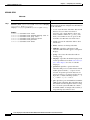
Configuring Distribution Lists
14-1
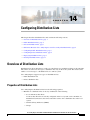
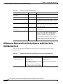
Overview of Distribution Lists 14-1
Properties of Distribution Lists 14-1
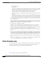
Public Distribution Lists
14-2
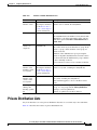
Private Distribution Lists
14-3
Differences Between Cisco Unity Express and Cisco Unity Distribution Lists
14-4
Configuring Public Distribution Lists 14-5
Prerequisites 14-6
Required Data for This Procedure 14-6
Examples 14-8
Configuring Private Distribution Lists
14-8
Displaying Distribution Lists 14-8
Displaying All Public Distribution Lists 14-8
Displaying Details of a Public Distribution List 14-9
Displaying an Owner’s Lists 14-10
Displaying Details of a Private Distribution List 14-10
Deleting Distribution Lists
CHAPTER
15
Configuring Security
Overview of Security
14-11
15-1
15-1
Obtaining a Certificate and Private Key 15-2
Generating a Certificate-Key Pair 15-2
Importing a Certificate-Key Pair 15-2
Displaying the Certificate-Key Pairs
15-3
Changing the Default Certificate-Key Pair
Deleting a Certificate-Key Pair
15-3
15-3
Accessing the Cisco Unity Express GUI Using HTTPS 15-4
Enabling HTTPS Access to the Cisco Unity Express GUI (Versions 3.0 and 3.1) 15-4
Prerequisites 15-4
Enabling HTTPS Access to the Cisco Unity Express GUI (Versions 3.2 and Higher) 15-5
Prerequisites 15-5
CHAPTER
16
Backing Up and Restoring Data
16-1
Restrictions 16-2
Backing Up from One Platform and Restoring to Another Platform Type
Setting Backup Parameters
Prerequisites 16-3
16-2
16-2
Cisco Unity Express Voice-Mail and Auto-Attendant CLI Administrator Guide for 3.0 and Later Versions
OL-14010-09
xiii
Contents
Required Data for This Procedure
Examples 16-4
16-3
Backing Up Files 16-4
Examples 16-5
Restoring Files 16-8
Example 16-9
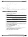
Copying Configurations 16-11
Copying from Flash Memory to Another Location 16-11
Copying from the Network FTP Server to Another Location 16-12
Copying the Flash Running Configuration to Another Location 16-12
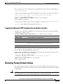
Copying the Network TFTP Configuration to Another Location 16-13
Restoring Factory Default Values
16-13
Backup and Restore Using SFTP 16-14
Overview 16-14
Configuring Backup and Restore Using SFTP 16-15
Prerequisites 16-15
Required Data for This Procedure 16-15
Backup Server Authentication Using a SSH Host Key 16-15
Overview 16-16
Configuring Backup Server Authentication Without Using the SSH Host Key
Prerequisites 16-16
Required Data for This Procedure 16-16
Configuring Backup Server Authentication Using the SSH Host Key 16-17
Prerequisites 16-17
Required Data for This Procedure 16-17
Encrypting and Signing of Backup Content on the Server 16-18
Overview 16-18
Configuring the Encryption and Signing of Backup Content on the Server
Prerequisites 16-19
Required Data for This Procedure 16-19
Encrypting PINs in Backup Files
16-16
16-19
16-20
Configuring Scheduled Backup Jobs 16-20
Prerequisites 16-21
Examples 16-23
Disabling or Reenabling All Scheduled Backups 16-23
Prerequisites 16-23
Configuring Scheduled Backup Notification 16-24
Prerequisites 16-24
Cisco Unity Express Voice-Mail and Auto-Attendant CLI Administrator Guide for 3.0 and Later Versions
xiv
OL-14010-09
Contents
CHAPTER
17
Language Support
17-1
Language Settings 17-1
AutoAttendant and IVR 17-1
Voice Mail 17-2
Administration Via Telephony 17-3
VoiceView 17-3
Message Notification 17-3
Subscriber Message Notification 17-4
Cascaded Message Notification 17-4
Nonsubscriber Message Notification 17-4
VoiceXML Web Applications 17-4
Uploading and Downloading Custom Prompts and Documents
Installation Considerations
17-5
Backup and Restore Considerations
CHAPTER
18
17-5
Configuring Advanced Voice Mail
17-5
18-1
Configuring IMAP 18-1
Overview 18-1
IMAP Server 18-2
E-mail Client Considerations 18-2
Configuring Integrated Messaging 18-5
Prerequisites 18-5
Required Data for This Procedure 18-5
Examples 18-8
Displaying IMAP Sessions 18-8
Support for Client Services Framework (CSF)-Based Clients
Configuring Live Record 18-9
Overview 18-9
Configuration 18-10
Using Live-Record 18-11
Error Conditions 18-11
Limitations 18-11
Configuring Live Record 18-11
Prerequisites 18-11
Required Data for This Procedure
Examples 18-13
Configuring Live Reply 18-13
Overview 18-13
Accessing Live-Reply from the TUI
18-8
18-12
18-14
Cisco Unity Express Voice-Mail and Auto-Attendant CLI Administrator Guide for 3.0 and Later Versions
OL-14010-09
xv
Contents
Accessing Live-Reply from VVE 18-14
Limitations 18-15
Configuration 18-16
Configuring Live Reply 18-17
Prerequisites 18-17
Required Data for This Procedure 18-18
Examples 18-20
Configuring the Delivery of Future Messages 18-21
Permitted Subscribers 18-21
Message Delivery Time 18-21
System Status Impact 18-22
Unsuccessful Message Delivery 18-22
Loss of Future Messages 18-22
Incorrect Message Delivery 18-22
Backup and Restore of Future Messages 18-23
Displaying and Deleting Future Messages 18-23
Configuring Nonsubscriber Message Delivery 18-23
Overview 18-23
Configuring Nonsubscriber Message Delivery 18-24
Prerequisites 18-24
Required Data for This Procedure 18-25
Examples 18-25
Configuring Broadcast Messages 18-26
Overview of Broadcast Messages 18-26
Configuring Broadcast Messages 18-27
Configuring a Group with Broadcast Privileges 18-27
Configuring the Broadcast Message Length and Expiration Time 18-27
Required Data for This Procedure 18-27
Examples 18-28
Enabling the MWI Lights for Broadcast Messages 18-28
Displaying Broadcast Messages 18-29
Displaying Current Broadcast Messages 18-29
Displaying Broadcast Messages Received Per Mailbox 18-29
Displaying Broadcast Messages Received by the Voice-Mail System 18-29
Deleting a Broadcast Message 18-30
Changing Broadcast Message Start and End Times 18-30
Disabling Broadcast Privileges for a Group 18-31
Disabling MWI Lights for Broadcast Messages 18-31
Configuring the Local-Broadcast Privilege 18-31
Cisco Unity Express Voice-Mail and Auto-Attendant CLI Administrator Guide for 3.0 and Later Versions
xvi
OL-14010-09
Contents
Prerequisites
Example 18-32
18-31
Configuring Restriction Tables 18-32
Overview 18-32
Toll Fraud Prevention 18-34
Configuring Restriction Tables 18-36
Creating a Restriction Table 18-36
Deleting a Restriction Table 18-37
Configuring a Restriction Table 18-38
CHAPTER
19
Advanced Configuration
19-1
Configuring the Hostname
Examples 19-2
Configuring the DNS Server
Examples 19-4
19-1
19-3
Configuring NTP Servers 19-4
Adding NTP Servers 19-4
Examples 19-5
Removing an NTP Server 19-7
Displaying NTP Server Information
Configuring a Syslog Server 19-8
Required Data for This Procedure
Examples 19-9
Configuring the Clock Time Zone
Examples 19-10
19-8
19-8
19-10
Configuring Password and PIN Parameters 19-12
Configuring Password and PIN Length and Expiry Time 19-12
Examples 19-14
Configuring Enhanced PIN Validation 19-14
Configuring Password and PIN Protection Lockout Modes 19-16
Configuring Password Protection with Permanent Lockout 19-17
Configuring PIN Protection with Permanent Lockout 19-18
Configuring Password Protection with Temporary Lockout 19-19
Configuring PIN Protection with Temporary Lockout 19-20
Configuring PIN and Password History 19-21
Configuring the Password History Depth 19-22
Configuring the PIN History Depth 19-22
Displaying Password and PIN System Settings 19-23
Encrypting PINs in Backup Files 19-24
Cisco Unity Express Voice-Mail and Auto-Attendant CLI Administrator Guide for 3.0 and Later Versions
OL-14010-09
xvii
Contents
Scheduling CLI Commands
Examples 19-27
CHAPTER
20
Monitoring the System
19-24
20-1
Monitoring Active Calls 20-1
Displaying Active Calls by Application 20-1
Displaying Active Calls by Route 20-3
Displaying Incoming Fax Calls 20-5
Terminating an Active Call 20-5
Monitoring Future Messages 20-6
Displaying Future Messages 20-6
Displaying All Future Messages 20-6
Displaying the Number of Future Messages for Each Subscriber 20-6
Displaying the Number of Scheduled Messages for a Subscriber 20-7
Deleting a Future Message 20-7
Monitoring Active IMAP and VoiceView Express Sessions 20-7
Displaying IMAP Sessions 20-8
Displaying VoiceView Express Sessions 20-8
Terminating an Active VoiceView Express Session 20-8
Monitoring Queues 20-9
Monitoring Network Queues 20-9
Monitoring Notification Queues 20-9
Monitoring Fax Queues 20-10
Displaying SNMP and Management Data Activity
Viewing System Activity Messages
20-12
Checking AIM Compact Flash Memory Wear Activity
CHAPTER
21
Viewing Historical Reports
20-13
Viewing Real Time Reports
20-13
Configuring SNMP Monitoring
20-10
20-13
21-1
Prerequisites for Implementing SNMP Monitoring on Cisco Unity Express
Enabling the SNMP Agent, Passwords, and Trap Server 21-1
Prerequisites 21-1
Required Data for This Procedure 21-2
Verifying the Enabling of the SNMP Agent, Passwords, and Trap Server
Setting Threshold Values for Subscriber Responses
Prerequisites 21-5
Required Data for This Procedure 21-5
21-1
21-4
21-4
Cisco Unity Express Voice-Mail and Auto-Attendant CLI Administrator Guide for 3.0 and Later Versions
xviii
OL-14010-09
Contents
Verifying the SNMP Login and PIN Notification Thresholds
21-7
Enabling Cisco Unity Express Shutdown Requests 21-7
Prerequisites 21-7
Verifying the Enabling of Shutdown Requests 21-8
CHAPTER
22
Registering Cisco Unity Express Endpoints to Cisco Unified Messaging Gateway
Overview of the Autoregistration Process
22-1
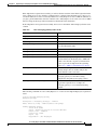
Configuring Autoregistration with Cisco UMG
SUMMARY STEPS 22-3
DETAILED STEPS 22-4
Example 22-6
22-2
Manually Registering a Cisco Unity Express Endpoint
Examples 22-10
22-6
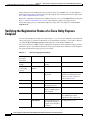
Verifying the Registration Status of a Cisco Unity Express Endpoint
22-12
Enabling or Disabling Remote Lookup, With or Without TUI Confirmation
Viewing Cached and/or Configured Network Locations
Refreshing Locations
22-14
22-15
Overloading a NAT Device: the Consequences for Endpoints
23
22-14
22-15
Setting the Expiration for Cached Locations
CHAPTER
22-1
22-15
Configuring Your Cisco IOS Gateway for T.37 On-Ramp and Off-Ramp Fax Support
23-1
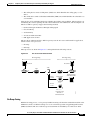
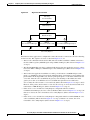
Deployment Scenarios 23-1
Fax Call Flow 23-2
On-Ramp Faxing 23-3
Off-Ramp Faxing 23-4
Configuration Options 23-4
Using Separate DIDs for Fax 23-5
Using a Single DID for Voice and Fax 23-5
Using Connect First Mode with Single DID 23-6
Using Connect First Mode with Separate DIDs 23-8
Using Listen First Mode with Single DID 23-8
Using Listen First Mode with Separate DID 23-9
Using the Fax Detection Application vs the On-ramp Application
Fax Feature Benefits and Limitations
23-9
23-10
Configuring Your Cisco IOS Gateway for T.37 On-Ramp and Off-Ramp Fax Support
Prerequisites 23-12
Configuring the Fax Gateway for T.37 On-Ramp 23-13
Prerequisites 23-13
23-12
Cisco Unity Express Voice-Mail and Auto-Attendant CLI Administrator Guide for 3.0 and Later Versions
OL-14010-09
xix
Contents
Required Data for This Procedure 23-13
Configuration Example 23-15
Configuring the Fax Gateway for T.37 Off-Ramp 23-15
Prerequisites 23-15
Required Data for This Procedure 23-16
Configuration Example 23-17
Configuring the Fax Gateway for the Fax Detection Application
Prerequisites 23-20
Required Data for This Procedure 23-21
CHAPTER
24
Troubleshooting
23-20
24-1
Troubleshooting Guidelines 24-1
System Reports 24-1
Log Files 24-2
Users and Groups 24-2
Hardware and Software 24-2
Rebooting the System 24-2
Setting Daylight Savings Time 24-3
Communicating Between Components 24-3
Online Insertion and Removal (OIR) 24-4
Saving and Viewing Log Files 24-4
Saving Configuration Changes 24-4
Voice Mail 24-5
Message Waiting Indicators (MWIs) (Cisco Unified CME Only)
Auto-Attendant Prompts 24-6
Checking Log and Trace Files 24-6
Troubleshooting Commands
24-5
24-6
Cisco Unity Express Voice-Mail and Auto-Attendant CLI Administrator Guide for 3.0 and Later Versions
xx
OL-14010-09
CH A P T E R
1
Cisco Unity Express Features
This guide describes the set of Cisco Unity Express CLI commands and tasks for configuring, managing,
and maintaining Cisco Unity Express applications, such as voice mail.
This guide complements the GUI administration tasks described in the Cisco Unity Express GUI
Administrator Guide.
The focus of this guide is the Cisco Unity Express application. It does not provide information on
installation of Cisco routers, Cisco network modules, Cisco Unified Communications Manager Express
router., or Cisco Unified Communications Manager server. For more information about those topics, see
Cisco Unity Express Documentation, By Version.
This chapter contains the following sections:
•
Platforms and Cisco IOS Software Images, page 1
•
Cisco Unity Express Feature List, page 2
Platforms and Cisco IOS Software Images
Cisco Unity Express applications use a set of commands that are similar in structure to Cisco IOS
software commands. However, Cisco Unity Express commands do not affect the Cisco IOS
configuration.
See the Release Notes for Cisco Unity Express for detailed information about the Cisco Unity Express
hardware and software platforms.
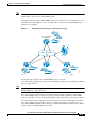
Note
We highly recommend attaching an uninterruptible power supply (UPS) to the router housing the
Cisco Unity Express module. Any reliable UPS unit provides continuous power to maintain the
operation of the router and the Cisco Unity Express module. Consider the unit’s capacity and run time
because power consumption differs among Cisco platforms. Ideally, a UPS should include a signaling
mechanism that directs the router to shut down Cisco Unity Express properly and then powers off the
router.
Supported Cisco Unified IP Phones
See the Release Notes for Cisco Unity Express 8.6 for details about supported Cisco Unity IP phones.
Cisco Unity Express Voice-Mail and Auto-Attendant CLI Administrator Guide for 3.0 and Later Versions
OL-14010-09
1-1
Chapter 1
Cisco Unity Express Features
Cisco Unity Express Feature List
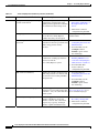
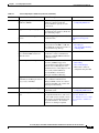
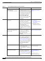
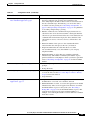
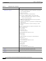
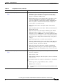
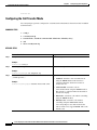
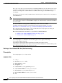
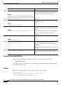
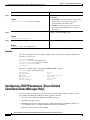
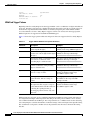
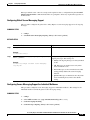
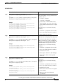
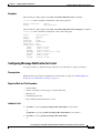
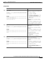
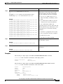
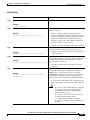
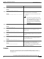
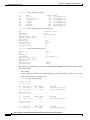
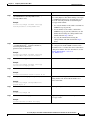
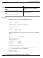
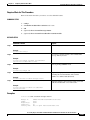
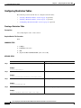
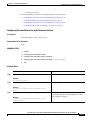
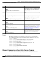
Cisco Unity Express Feature List
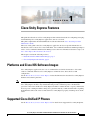
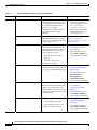
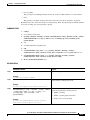
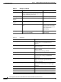
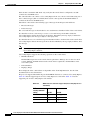
Table 1-1 lists Cisco Unity Express features by version. Features that are introduced in a particular
version are available in that and subsequent versions.
Tip
Table 1-1
Table 1-1 describes how to configure each feature using the GUI, where applicable. For information
about how to use the GUI to configure a feature, see the online help at:
•
Configuring Cisco Unity Express Using the GUI: Privilege Mode for Cisco Unified Communications
Manager
•
Configuring Cisco Unity Express Using the GUI: Privilege Mode for Cisco Unified Communications
Manager Express
•
Configuring Cisco Unity Express Using the GUI: Administrator User Mode for All Licenses
Cisco Unity Express Features by Version
Version
Features Introduced in That Version1
Feature Description
8.6
Support for Cisco Unity Express on
SM-SRE-710-K9 and
SM-SRE-910-K9 Services Ready
Engine (SRE) modules
Provides support for Cisco Unity
Express on SM-SRE-710-K9 and
SM-SRE-910-K9 Services Ready
Engine modules for the Cisco 2900
Series and Cisco 3900 Series routers.
•
See Release Notes for
Cisco Unity Express 8.6.
•
See Cisco SRE Service
Module Configuration and
Installation Guide.
Editor Express Enhancements
Enhancements have been made to the
GUI for Editor Express. Additional
menu options have been added.
•
See the online help and
Configuring Cisco Unity
Express 8.6 Using the
GUI.
Fax Preview
Fax Preview displays a preview of the
fax message attachment in the
VoiceView Express interface on the
screen of Cisco IP Phones.
•
See the Cisco Unity
Express 8.6 User’s Guide
for Advanced Features and
the Cisco Unity Express
8.6 VoiceView Express
Quick Start Guide.
Fax Preview is supported on selected
Cisco Unified IP phones. See the
Release Notes for Cisco Unity Express
8.6 for more information.
Feature Information
Cisco Unity Express Voice-Mail and Auto-Attendant CLI Administrator Guide for 3.0 and Later Versions
1-2
OL-14010-09
Chapter 1
Cisco Unity Express Features
Cisco Unity Express Feature List
Table 1-1
Version
Cisco Unity Express Features by Version (continued)
Features Introduced in That Version1
Feature Description
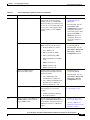
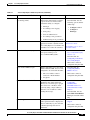
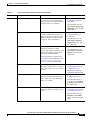
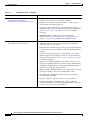
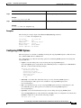
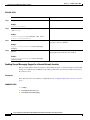
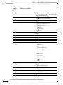
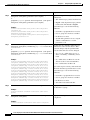
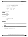
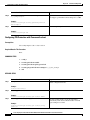
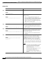
Secure Messaging
Secure messaging allows you to
configure the secure messaging
settings globally or for individual
mailboxes. Messages marked secure
can only be accessed if the subscriber
accesses Cisco Unity Express Web
Voicemail using a secure HTTPS
session.
•
From the CLI, see
Configuring Secure
Messaging.
•
From the GUI: Use the
Voice Mail > VM
Configuration option for
configuring the global
secure messaging setting,
and the Voice Mail >
Mailboxes option for
configuring the secure
messaging setting for a
mailbox.
Provides support for the following
IMAP clients new in this release:
•
From the CLI, see
Configuring IMAP.
•
From the GUI: Use the
Voice Mail > Integrated
Messaging > Service
Configuration option.
•
From the CLI, see
Configuring IMAP.
•
From the GUI: Use the
Voice Mail > Integrated
Messaging > Service
Configuration option.
Support for New IMAP Clients
Support for Client Services
Framework (CSF) clients
Support of additional languages
8.5
Support for Cisco Unity Express on
SM-SRE-900-K9 Services Ready
Engine (SRE) module
•
IP Phone third party clients
•
Cisco Mobile 8.0
•
Microsoft Outlook 2010
•
Microsoft Entourage 2008
•
Microsoft Windows Live Mail
12.0
•
IBM Lotus Notes 8.5
•
IBM Lotus Notes 8.0
•
IBM Lotus Notes 7.0
Provides support for the following
clients that use the Client Services
Framework (CSF):
•
Cisco Unified Personal
Communicator (CUPC) 8.5
•
Cisco Unified Communications
Integration™ for Microsoft
Office Communicator 8.0
Provides support for the following
new languages for voice-mail
prompts:
•
Traditional Chinese (Taiwan)
•
Hong Kong Chinese
Provides support for Cisco Unity
Express on SM-SRE-900-K9 Services
Ready Engine modules for the Cisco
2900 Series and Cisco 3900 Series
routers.
Feature Information
See the Release Notes for
Cisco Unity Express 8.6.
•
See Release Notes for
Cisco Unity Express 8.5.
•
See Cisco SRE Service
Module Configuration and
Installation Guide.
Cisco Unity Express Voice-Mail and Auto-Attendant CLI Administrator Guide for 3.0 and Later Versions
OL-14010-09
1-3
Chapter 1
Cisco Unity Express Features
Cisco Unity Express Feature List
Table 1-1
Version
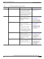
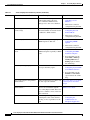
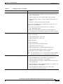
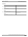
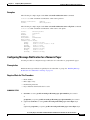
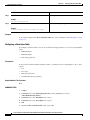
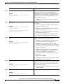
8.0
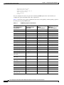
Cisco Unity Express Features by Version (continued)
Features Introduced in That Version1
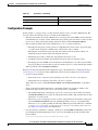
Feature Description
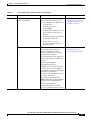
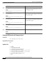
Web Inbox GUI for VoiceMail
Subscribers
Provides a separate web-based user
GUI for voicemail subscribers to
configure subscriber settings.
Functions available through the web
user GUI include:
•
Creating greetings
•
Recording the spoken name
•
Modifying the personal profile
and the GDM profile
•
Adding and deleting private
distribution lists
•
Selecting how to be notified when
receiving a voicemail
•
Having Cisco Unity Express
transfer the call to another
number
Support for Cisco Unity Express on
SM-SRE-700-K9 Services Ready
Engine (SRE) module
Provides support for Cisco Unity
Express on SM-SRE-700-K9 Services
Ready Engine modules for the Cisco
2900 Series and Cisco 3900 Series
routers.
Auto Configuration
When the system boots initially after a
clean installation, the administrator is
prompted whether to configure the
system. If no response is provided
within 120 seconds, and there is no
default configuration or startup
configuration, the system auto
configures Cisco Unity Express to the
following settings:
Message Notification enhancement
•
Default primary NTP server to the
host router
•
Time zone set to GMT
•
Call agent set to CCM
•
DNS set to nothing
Enables an administrator to append a
prefix message before a system-wide
notification or a signature message
after a system-wide notification.
Feature Information
•
See the GUI online help.
•
See Release Notes for
Cisco Unity Express 8.0.
•
See Cisco SRE Service
Module Configuration and
Installation Guide.
•
From the CLI, see
Configuring System-Wide
Settings.
•
From the GUI: Use the
Voice Mail > Message
Notification > Subscriber
Notification
Management option.
Cisco Unity Express Voice-Mail and Auto-Attendant CLI Administrator Guide for 3.0 and Later Versions
1-4
OL-14010-09
Chapter 1
Cisco Unity Express Features
Cisco Unity Express Feature List
Table 1-1
Version
Cisco Unity Express Features by Version (continued)
Features Introduced in That Version1
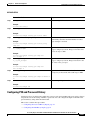
Feature Description
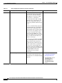
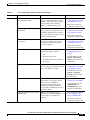
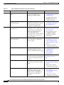
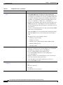
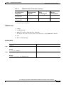
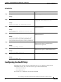
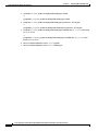
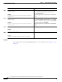
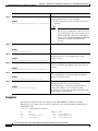
New AAA user steps for Cisco Unity Cisco Unity Express Script Editor
Express Script Editor
supports four new AAA user steps:
Programmatic Interface for XML
•
User Authenticate: Authenticates
a user based on
username/password or
extension/PIN
•
Authorize User: Authorizes a user
based against an operation or a
privilege
•
Audit Step: Step for logging audit
information for the user
•
Logout User: Logs out a
previously authenticated user
from the system
Feature Information
•
See the Cisco Unity
Express Guide to Writing
and Editing Scripts for 7.0
and Later Versions
Provides a set of well defined API and See the Cisco Unity Express
Programmatic Interface
data structures which external
Service Programming Guide.
software systems can invoke to
perform configurations on the Cisco
Unity Express system. The
programmatic interface is supported
in Cisco Unity Express 8.0 and later
versions.
The Cisco Unity Express
programmatic interface is
implemented as a web service. Like
most web services, it uses HTTP as
the communication protocol and XML
documents for exchanging
information between client and server.
The service is based on
Representational State Transfer
(REST) architecture and uses JAX-RS
specifications for implementation.
The Cisco Unity Express
programmatic interface provides
access for configuration purpose only
Cisco Unity Express Voice-Mail and Auto-Attendant CLI Administrator Guide for 3.0 and Later Versions
OL-14010-09
1-5
Chapter 1
Cisco Unity Express Features
Cisco Unity Express Feature List
Table 1-1
Version
Cisco Unity Express Features by Version (continued)
Features Introduced in That Version1
Feature Description
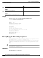
Stored Caller Name
Cisco Unity Express 8.0 adds support
for storing the caller's name if the
caller is a non-subscriber. When Cisco
Unity Express receives the calling
party name for a subscriber or
non-subscriber in the SIP or JTAPI
signaling, Cisco Unity Express 8.0
stores the calling party name, the
calling party number and the message
itself.
Feature Information
For new voicemails being deposited
through the TUI, Cisco Unity Express
now stores the calling party name
along with the message if the name is
present in the call signaling. For fax
messages received by Cisco Unity
Express through SMTP, the system
stores the display name present in the
RFC 5322 From header field along
with the fax message.
For messages received through VPIM,
Cisco Unity Express now stores the
display name present in the From
header field along with the message.
When a sender name is available for a
message, the system includes that
name (in textual form) in IMAP, VVE,
Web voicemail, message notifications
and in SIP MWI notifications
containing message envelope
information.
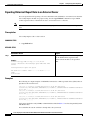
System Backup enhancements
Enables an administrator to configure
the system to notify specific users
about the status of a scheduled backup
operation.
•
From the CLI, see
Configuring Scheduled
Backup Notification.
•
From the GUI: Use the
Administration >
Backup/Restore >
Scheduled Backups
option.
Cisco Unity Express Voice-Mail and Auto-Attendant CLI Administrator Guide for 3.0 and Later Versions
1-6
OL-14010-09
Chapter 1
Cisco Unity Express Features
Cisco Unity Express Feature List
Table 1-1
Version
Cisco Unity Express Features by Version (continued)
Features Introduced in That Version1
Feature Description
Voicemail User GUI
Voicemail subscribers can access
Cisco Unity Express voicemail using
the GUI. Functions available through
the user GUI include:
Wildcard match for pilot number
•
Creating greetings
•
Recording the spoken name
•
Modifying the personal profile
and the GDM profile
•
Adding and deleting private
distribution lists
•
Selecting how to be notified when
receiving a voicemail
•
Have Cisco Unity Express
transfer the call to another
number
Allows an administrator to use
wildcard characters when specifying
SIP and JTAPI trigger numbers.
Feature Information
•
From the CLI, see
Configuring SIP Triggers
for the Applications.
7.4
Release provides continued support
for Cisco Unity Express AIM-CUE.
No other hardware platforms are
supported in this release.
•
See Release Notes for
Cisco Unity Express 7.4.
7.3
Release provides continued support
for Cisco Unity Express AIM-CUE.
No other hardware platforms are
supported in this release.
•
See Release Notes for
Cisco Unity Express 7.3.
7.2
Release provides continued support
for Cisco Unity Express AIM-CUE.
No other hardware platforms are
supported in this release.
•
See Release Notes for
Cisco Unity Express 7.2.
7.1.2
Support for Cisco Unity Express on
ISM-SRE-300-K9 Services Ready
Engine (SRE) module
Provides support for Cisco Unity
Express on the ISM-SRE-300-K9
Services Ready Engine module for the
Cisco 2900 Series and Cisco 3900
Series routers
•
See Release Notes for
Cisco Unity Express 7.1.
•
See Cisco SRE Service
Module Configuration and
Installation Guide
Support for AIM2-CUE module.
The AIM2-CUE module is a
replacement for the existing
AIM-CUE module. Unless otherwise
noted, the performance and system
capacities are the same on both
modules in this release.
•
See Release Notes for
Cisco Unity Express 7.1.
Cisco Unity Express Voice-Mail and Auto-Attendant CLI Administrator Guide for 3.0 and Later Versions
OL-14010-09
1-7
Chapter 1
Cisco Unity Express Features
Cisco Unity Express Feature List
Table 1-1
Cisco Unity Express Features by Version (continued)
Version
Features Introduced in That Version1
Feature Description
7.1.1
Phone and platform support.
Supports the use of new phones with
VoiceView Express and support for
interoperability with new versions of
Cisco Unified Communications
Manager, Cisco Unified
Communications Manager Express,
Cisco Unity, and Cisco Unity
Connection.
New software activation method
Support for Cisco Software Licensing
(CSL). Beginning with Cisco Unity
Express 7.1.1, software licenses must
be activated prior to use.
Caller input
Enables callers to control how the call
flow precedes by pressing keys. For
each mailbox, the mailbox owner or
system administrator can assign
actions to the keys such as:
Scheduled backups
Announcement-Only mailboxes
Multiple greetings
Feature Information
•
For a list of the phone
models and application
versions supported, see the
Cisco Unity Express
Compatibility Matrix, for
links to the compatibility
information for each call
control application.
For more information, see
Software Activation for
Cisco Unity Express 7.1 and
Later Versions.
•
From the CLI: See
Configuring Call Flow
Customization.
•
From the GUI: Use the
Voice Mail > Mailboxes
option and the online help
•
From the CLI: See
Configuring Scheduled
Backup Jobs.
•
From the GUI: Use the
Administration >
Backup/Restore >
Scheduled Backups
option and the online help
Enables you to configure
announcement-only mailboxes. These
mailboxes can only play the user
greeting and disconnect the call; they
cannot take any messages from callers
or send messages.
•
From the CLI: See
Configuring an
Announcement-Only
Mailbox.
•
From the GUI: Use the
Voice Mail > Mailboxes
option and the online help
Enables users and Administrators to:
•
From the CLI: See
Configuring Multiple
Greetings
•
From the GUI: Use the
Voice Mail > Mailboxes
option and the online help
•
Transfer the call to another
number
•
Connect to the operator
•
Repeat the greeting
Enables you to configure up to five
recurring scheduled backup jobs and
five one-time scheduled backup jobs.
•
Record multiple greetings
•
Select which greetings to use
•
Enable or disable greetings
Cisco Unity Express Voice-Mail and Auto-Attendant CLI Administrator Guide for 3.0 and Later Versions
1-8
OL-14010-09
Chapter 1
Cisco Unity Express Features
Cisco Unity Express Feature List
Table 1-1
Cisco Unity Express Features by Version (continued)
Version
Features Introduced in That Version1
Feature Description
7.0
Authentication, Authorization, and
Accounting (AAA)
Expands on the authentication and
authorization functionality available
in previous releases. New features
include the ability to configure:
3.2
•
Privileges
•
Accounting events logging
•
AAA policy
•
Console authentication
•
Accounting server parameters
•
Authenticating server parameters
Feature Information
•
From the CLI: See
•
From the GUI: Use the
following options and the
online help:
– Configure > AAA
– Configure >
Privileges
TimeCardView
TimeCardView 7.0 CLI
TimeCardView is a separate
application used in conjunction with Administrator Guide
Cisco Unity Express to track time and
TimeCardView 7.0 for Users
attendance for workers in a business.
Quick Start Guide
Centralized Cisco Unity Express
Enables Cisco Unity Express NME to
interoperate with up to ten
Cisco Unified CME systems.
Voice mailbox PINless login
Nonsubscriber distribution lists
Banner support
•
See the documentation for
Cisco Unified Messaging
Gateway 1.0.
•
From the CLI: See
Configuring Centralized
Cisco Unity Express
•
This feature cannot be
configured using the GUI.
•
From the CLI: See
Configuring PINless
Mailbox Access
•
This feature cannot be
configured using the GUI.
Enables you to add nonsubscribers to
distribution lists. This enables the
delivery of voice messages to people
who do not have a mailbox on the
system by using a single address to
reference a list of addresses when
sending the message.
•
From the CLI: See
Configuring
NonSubscriber
Distribution Lists for
Centralized Cisco Unity
Express
•
From the GUI: Use the
Voice Mail > Distribution
Lists option and the online
help.
Enables you to configure a system
wide login banner that is displayed to
all users when they log in to the CLI
or GUI and prompts the user for
credentials.
•
From the CLI: See Banner
Support
•
This feature cannot be
configured using the GUI.
Enables subscribers to log in to their
mailbox without a PIN. Access can be
configured to be allowed from either:
•
The voice mailbox owner’s
extension or E.164 number
•
Any phone
Cisco Unity Express Voice-Mail and Auto-Attendant CLI Administrator Guide for 3.0 and Later Versions
OL-14010-09
1-9
Chapter 1
Cisco Unity Express Features
Cisco Unity Express Feature List
Table 1-1
Version
Cisco Unity Express Features by Version (continued)
Features Introduced in That Version1
Feature Description
Inclusion of envelope information in Enables you to determine whether
SIP MWI notifications
envelope information is included in
SIP MWI notifications
Certificate Association for HTTPS
and IMAP
3.1
Support for Cisco Unified
Communications Manager 6.1 and
4.3(1)
Associates a certificate key for
HTTPS and IMAP. Associates a
certificate key for HTTPS, or
associates a certificate key for SSL on
IMAP.
Cisco Unity Express 3.1.2 supports
interoperability with Cisco Unified
Communications Manager 4.3(1).
Cisco Unity Express 3.1 provides
interoperability with Cisco Unified
Communications Manager 6.1.
Support of additional languages
Provides support for several new
languages for voice-mail prompts.
Support for automatic registration
with Cisco Unified Messaging
Gateway 1.0
Provides automatic registration and
interoperability with Cisco Unified
Messaging Gateway 1.0, which
provides a tool for system
administrators to manage large
numbers of Cisco Unity Express
endpoints in a distributed network.
Support for storing historical reports In release 3.0, historical reports about
on remote sites
call activities and application
activities on the system could only be
stored locally. Beginning with
release 3.1, the historical reports can
be stored on remote databases.
Feature Information
•
From the CLI: See
Configuring the Inclusion
of Envelope Information in
SIP MWI Notifications
•
This feature cannot be
configured using the GUI.
•
From the CLI: For HTTPS,
see Enabling HTTPS
Access to the Cisco Unity
Express GUI (Versions 3.2
and Higher). For IMAP,
see Configuring IMAP.
•
This feature cannot be
configured using the GUI.
See the documentation for
Cisco Unified
Communications Manager 6.1
and 4.3(1).
See the Release Notes for
Cisco Unity Express 3.1 for a
list of available languages.
•
See the documentation for
Cisco Unified Messaging
Gateway 1.0.
•
From the CLI: See
Registering Cisco Unity
Express Endpoints to
Cisco Unified Messaging
Gateway
•
This feature cannot be
configured using the GUI.
•
See the Cisco Unified
Communications Express
Historical Reporting
Client Configuration
Guide.
•
From the CLI: See
Configuring Historical
Reporting
•
From the GUI: Use the
Administration >
Historical Reporting
option and the online help.
Cisco Unity Express Voice-Mail and Auto-Attendant CLI Administrator Guide for 3.0 and Later Versions
1-10
OL-14010-09
Chapter 1
Cisco Unity Express Features
Cisco Unity Express Feature List
Table 1-1
Version
3.0
Cisco Unity Express Features by Version (continued)
Features Introduced in That Version1
Feature Description
New voice mail subscriber feature
See the documentation for
Provides voice-mail users with the
option of searching a global directory Cisco Unified Messaging
Gateway 1.0.
if an extension is not found when
addressing a message by name or
number. This feature is only available
if the voice-mail system is running in
an environment managed by the Cisco
Unified Messaging Gateway.
Fax
Extends the convergence feature set to
include fax support. It allows both
inbound and outbound faxes.
Outbound faxes can be printed to the
fax machine.
•
From the CLI: See
Configuring System-Wide
Fax Parameters
•
From the GUI: Use the
System > Fax Settings
option and the online help.
Extends the existing message
notification feature that was
introduced in 2.3(1). With this feature,
you can:
•
From the CLI: See
Cascading Message
Notification
•
From the GUI: Use the
Voice Mail > Message
Notification option and
the online help.
Enables Cisco Unity Express
subscribers to record live
conversations and store the recording
as a message in their mailbox. They
can then play it or forward it to
another subscriber or group of
subscribers.
•
From the CLI: See
Configuring Live Record
•
From the GUI: Use the
Voice Mail > VM
Configuration option and
the online help.
Enables Cisco Unity Express
subscribers to make a phone call to a
voice message’s sender while
listening to the message, by pressing
4-4.
•
From the CLI: See
Configuring Live Reply
•
From the GUI: Use the
Voice Mail > VM
Configuration option and
the online help.
Cascading Message Notification
Live Record
Live Reply
•
Set up a series of cascading
notifications to recipients
•
Enable subscribers to define
time-based rules that determine
how the notification is cascaded
to other local subscribers.
Feature Information
Cisco Unity Express Voice-Mail and Auto-Attendant CLI Administrator Guide for 3.0 and Later Versions
OL-14010-09
1-11
Chapter 1
Cisco Unity Express Features
Cisco Unity Express Feature List
Table 1-1
Version
Cisco Unity Express Features by Version (continued)
Features Introduced in That Version1
Feature Description
Historical reports
Provides historical reports about call
activities and application activities on
the system.
Feature Information
•
See the Cisco Unified
Communications Express
Historical Reporting
Client Configuration
Guide.
•
From the CLI: See
Configuring Historical
Reporting
•
From the GUI: Use the
Administration >
Historical Reporting
option and the online help.
Script Editor Express
Provides a simplified GUI that
enables you to create and modify
autoattendant scripts that can be
opened/viewed on the
Cisco Unity Express editor.
•
From the GUI: Use the
System > Scripts option
(click the New button) and
the online help.
Fixed holidays
Enables you to configure specific
dates as fixed or permanent holidays.
•
From the CLI: See
Configuring Holiday Lists
•
From the GUI: Use the
System > Holiday
Settings option and the
online help.
•
From the CLI: See
Configuring
Nonsubscriber Message
Delivery
•
From the GUI: Use the
Voice Mail > VM
Configuration option and
the online help.
Nonsubscriber message delivery
Enables Cisco Unity Express
subscribers to record a voice message
and send it to an external number or
nonsubscriber. The message can be
sent immediately or can be scheduled
to be sent in the future, up to 1 year in
advance.
New method of sending voice mail
Provides Cisco Unity Express script
developers with a new step: “Send
Voice Message.” It enables them to be
able to generate a message on the fly
by concatenating some prompts and
sending it to a Cisco Unity Express
subscriber.
Leaving multiple voice messages in
the same session
Enables callers to leave multiple voice
messages for the same or different
subscriber without having to be
transferred to the operator first.
No configuration is required
for this feature. For more
information, see the
Cisco Unity Express Guide to
Writing and Editing Scripts.
•
From the CLI: See
Configuring System-Wide
Voice-Mail Parameters
•
This feature cannot be
configured using the GUI.
Cisco Unity Express Voice-Mail and Auto-Attendant CLI Administrator Guide for 3.0 and Later Versions
1-12
OL-14010-09
Chapter 1
Cisco Unity Express Features
Cisco Unity Express Feature List
Table 1-1
Version
Cisco Unity Express Features by Version (continued)
Features Introduced in That Version1
Feature Description
Feature Information
Use of a voice-mail summary prompt Provides a system-wide configuration
during subscriber login
option to enable subscribers to hear a
summary of the new messages in the
corresponding General Delivery
Mailboxes (GDMs) during login.
•
From the CLI: See
Configuring System-Wide
Voice-Mail Parameters
•
This feature cannot be
configured using the GUI.
Message properties (envelope)
customization
Enables you to customize voice mail
message playback preferences, such
as whether subscribers hear detailed
message properties when they retrieve
a message using the TUI.
•
From the CLI: See
Configuring System-Wide
Voice-Mail Parameters
•
This feature cannot be
configured using the GUI.
Enables you to specify whether voice
messages are addressed by name or
extension be default at the system
level for all features.
•
From the CLI: See
Configuring System-Wide
Voice-Mail Parameters
•
This feature cannot be
configured using the GUI.
You can now restrict access to the
functionality of these features:
•
From the CLI: See
Configuring Restriction
Tables
•
From the GUI: Use the
System > Restriction
Tables option and use the
online help.
•
From the CLI: See
Configuring System-Wide
Voice-Mail Parameters
•
From the GUI: Use the
System > Language
Settings option and use
the online help.
Enhances the backup and restore
functionality to use the Secure File
Transfer Protocol (SFTP) for
transferring files to and from the
backup server. SFTP provides data
integrity and confidentiality that is not
provided by FTP.
•
From the CLI: See Backup
and Restore Using SFTP
•
From the GUI: Use the
Administration >
Backup/Restore option
and use the online help.
Backup Server Authentication Using Enables you to authenticate the
a SSH Host Key
backup server using the SSH protocol
before starting a backup/restore
operation.
•
From the CLI: See Backup
Server Authentication
Using a SSH Host Key
•
This feature cannot be
configured using the GUI.
Default addressing for sending a
voice message
Restriction tables
Language support
Backup and restore using SFTP
•
Fax
•
Message notification
•
Nonsubscriber message delivery
•
Live reply
Enables you to install and use more
than one language concurrently on the
Cisco Unity Express module.
Cisco Unity Express Voice-Mail and Auto-Attendant CLI Administrator Guide for 3.0 and Later Versions
OL-14010-09
1-13
Chapter 1
Cisco Unity Express Features
Cisco Unity Express Feature List
Table 1-1
Version
Cisco Unity Express Features by Version (continued)
Features Introduced in That Version1
Feature Description
Encryption and Signing of Backup
Content on the Server
Enables you to protect backed up
configuration and data files using
signing and encryption before the files
are transferred to the backup server.
•
From the CLI: See
Encrypting and Signing of
Backup Content on the
Server
•
This feature cannot be
configured using the GUI.
Encrypting stored PINs
Before 3.0, PINs were stored as clear No configuration is required
text on the Cisco Unity Express
for this feature.
module. Now, they are encrypted.
Increased password and PIN
protection
Provides both temporary and
permanent lockout for passwords and
PINs to help prevent security
breaches.
•
From the CLI: See
Configuring Password and
PIN Parameters
•
From the GUI: Use the
Configure > User
Defaults option and use
the online help.
You can use HTTPS to secure the
transmission of GUI pages between
the browser and the
Cisco Unity Express system.
•
From the CLI: See
Enabling HTTPS Access
to the Cisco Unity Express
GUI (Versions 3.0 and 3.1)
•
From the GUI: This
feature cannot be
configured using the GUI.
•
From the CLI: See
Configuring Password and
PIN Parameters
•
From the GUI: Use the
Configure > User
Defaults option and use
the online help.
Using HTTPS to access the GUI
PIN and Password History
2.3
Feature Information
Enables the system to track previous
PINs and passwords for all users and
prevent users from reusing old PINs
and passwords.
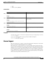
Support of additional languages
See the Release Notes for
Provides support for several new
languages for voice-mail prompts. For Cisco Unity Express 2.3 for a
Version 2.3, only one can be installed list of available languages.
on the system.
Increased system capacity
Provides support for increased
number of mailboxes, increased
number of remote and cached users,
larger storage capacity, and larger
number of public distribution lists.
•
From the CLI: See
Recording a Prompt File
•
This feature cannot be
configured using the GUI.
Cisco Unity Express Voice-Mail and Auto-Attendant CLI Administrator Guide for 3.0 and Later Versions
1-14
OL-14010-09
Chapter 1
Cisco Unity Express Features
Cisco Unity Express Feature List
Table 1-1
Version
Cisco Unity Express Features by Version (continued)
Features Introduced in That Version1
Feature Description
Integrated Messaging
Cisco Unity Express voice-mail
subscribers can access and manage
their voice messages and e-mail using
an e-mail client on a single PC.
•
From the CLI: See
Configuring Advanced
Voice Mail
•
From the GUI: Use the
Voice Mail > Integrated
Messaging option and the
online help.
Cisco Unity Express can notify
voice-mail subscribers of new voice
messages on their cell phones, home
phones, work phones, numeric pagers,
text pagers, and e-mail inboxes.
•
From the CLI: See
Configuring Message
Notification
•
From the GUI: Use the
Voice Mail > Message
Notification option and
the online help.
Cisco Unity Express voice-mail
subscribers can browse, listen,
manage, and send voice messages and
manage their mailbox options from
their Cisco Unified IP phone.
•
From the CLI: See
•
From the GUI: Use the
Voice Mail > VoiceView
Express option and the
online help.
Voice-mail subscribers can schedule
messages to be delivered at a future
time to subscribers on local or remote
systems.
•
From the CLI: See
Configuring the Delivery
of Future Messages
•
This feature cannot be
configured using the GUI.
Voice-mail subscribers with this
privilege can send broadcast messages
only to other voice-mail subscribers
on the local system.
•
From the CLI: See
Configuring Privileges
•
From the GUI: Select a
group from the Configure
> Groups option and use
the online help.
This configurable option specifies the
mailbox in which a voice message is
stored.
•
From the CLI: See
Configuring System-Wide
Voice-Mail Parameters
•
From the GUI: Use the
Defaults > Voice Mail
option and use the online
help.
Message Notification
VoiceView Express
Feature Information
VoiceView Express is supported on
selected Cisco Unified IP phones. See
the Release Notes for Cisco Unity
Express 8.6 for more information.
Future message delivery
Local broadcast privilege
Mailbox selection
Cisco Unity Express Voice-Mail and Auto-Attendant CLI Administrator Guide for 3.0 and Later Versions
OL-14010-09
1-15
Chapter 1
Cisco Unity Express Features
Cisco Unity Express Feature List
Table 1-1
Version
Cisco Unity Express Features by Version (continued)
Features Introduced in That Version1
Feature Description
Voice mail box mask
Permits Cisco Unity Express to send a
redirected incoming call from
Cisco Unified Communications
Manager 4.2 to the correct mailbox.
•
From the CLI: See
Unlocking a Voice
Mailbox
•
This feature cannot be
configured using the GUI.
Cisco Unity Express permits attended
and semiattended call transfer modes
in addition to blind transfers.
•
From the CLI: See
Configuring the Call
Transfer Mode
•
This feature cannot be
configured using the GUI.
•
From the CLI: See
Configuring DTMF
Options
•
This feature cannot be
configured using the GUI.
•
From the CLI: See
Configuring the MWI
Notification Option
•
From the GUI: Use the
Voice Mail > Message
Waiting Indicators >
Settings option and use
the online help.
•
From the CLI: See
Configuring System-Wide
Voice-Mail Parameters
•
From the GUI: Use the
Defaults > Voice Mail
option and use the online
help.
Consulting call transfers (SIP Call
Control only)
DTMF relay (SIP Call Control only) Handles incoming and outgoing
DTMF signals for SIP calls.
MWI Notifications in Cisco SRST
mode
Mandatory message expiry
Cisco Unity Express includes the
MWI status update capability to SRST
mode.
Forces the subscriber to delete
messages when they expire.
Feature Information
Cisco Unity Express Script Editor
enhancements
Enhanced debugging procedures and
two new steps are available.
Cisco Unity Express 2.3 Guide
to Writing Auto-Attendant
Scripts
Cisco Unity Express GUI
enhancements
Cisco Unity Express 2.3 GUI
New configuration screens and
Administrator Guide
options are available through the
Cisco Unity Express GUI. These new
options as similar to most of the new
CLI commands.
AvT enhancements
Rerecording existing prompts and
returning the status of the alternate
greeting are new capabilities for the
AvT.
•
From the CLI: See
Configuring the
Administration via
Telephone Application
Cisco Unity Express Voice-Mail and Auto-Attendant CLI Administrator Guide for 3.0 and Later Versions
1-16
OL-14010-09
Chapter 1
Cisco Unity Express Features
Cisco Unity Express Feature List
Table 1-1
Version
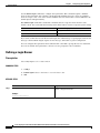
2.2
2.1
Cisco Unity Express Features by Version (continued)
Features Introduced in That Version1
Feature Description
Feature Information
Support for
Cisco Unified Communications
Manager 4.2 and 5.0
Cisco Unity Express now supports
two new versions in addition to
Cisco Unified Communications
Manager 4.1. Previous versions are
not supported.
—
Change in AIM-CUE support.
Cisco Unity Express does not support —
the 512 MB AIM-CUE.
CISCO-UNITY-EXPRESS-MIB
Monitor the health, conduct
performance monitoring, data
collection, and trap management for
Cisco Unity Express voice mail and
auto attendant applications.
•
From the CLI: See
Configuring SNMP
Monitoring
•
This feature cannot be
configured using the GUI.
Additional languages support.
Danish, U.K. English, Latin American Cisco Unity Express 2.1
Installation and Upgrade
Spanish, Italian, and Brazilian
Portuguese were added as choices for Guide
the default language of the telephone
user interface (TUI) system prompts
and greetings.
Distribution lists.
Create public and private distribution
lists of local and remote subscribers
for sending messages to more than
one subscriber.
•
From the CLI: See
Configuring Distribution
Lists
•
From the GUI: Use the
Voice Mail > Distribution
Lists option and the online
help.
Privileged subscribers can send
messages to all subscribers on the
network.
•
From the CLI: See
Configuring Broadcast
Messages
•
From the GUI: Use the
Configure > Groups
option and the online help.
•
From the CLI: See
Configuring Business
Hours and Configuring
Holiday Lists
•
Cisco Unity Express CLI
Administrator Guide.
•
From the GUI: Use
Voice Mail > Holidays
Settings and Voice Mail >
Business Hours Settings
and the online help.
Broadcast messages.
Schedules for holidays and business Create schedules of holidays and
hours.
business hours to automatically play
alternate auto attendant greetings to
callers.
Cisco Unity Express Voice-Mail and Auto-Attendant CLI Administrator Guide for 3.0 and Later Versions
OL-14010-09
1-17
Chapter 1
Cisco Unity Express Features
Cisco Unity Express Feature List
Table 1-1
Version
Cisco Unity Express Features by Version (continued)
Features Introduced in That Version1
Feature Description
Increased security for passwords and Set minimum lengths and expiry times
PINs.
for passwords and personal
identification numbers (PINs).
Feature Information
•
From the CLI: See
Configuring Password and
PIN Parameters
•
From the GUI: Use the
Defaults > User option
and the online help.
Permits playing of caller
identification information as part of
the message envelope for new
incoming voice mail messages.
•
From the CLI: See
Configuring Caller ID for
Incoming Messages
Addition of remote subscribers to the Adds frequently called remote
local directory.
subscribers to the local directory,
which permits local subscribers to
address voice mail messages to
remote subscribers using
dial-by-name and to receive spoken
name verification of the remote
subscriber address.
•
From the CLI: See Adding
Remote Subscribers to the
Local Directory
•
From the GUI: Use the
Configure > Remote
Users option and the
online help.
Support for vCard information from Permits vCard information from
remote subscribers.
remote subscribers to update their
directory entries.
•
From the CLI: See
Configuring a Location
with vCard Information
and Configuring the LRU
Cache
•
This feature cannot be
configured using the GUI.
•
From the CLI: See
Configuring and
Managing the
Auto-Attendant
Application
Support for caller ID information in
incoming messages.
Simple auto-attendant script.
Simple aa_simple.aef script is
available for handling alternate,
holiday, and business hours greetings.
Undelete voice messages.
Permits subscribers to restore a voice Cisco Unity Express
mail message that was deleted during Voice-Mail System User’s
Guide
the current voice message retrieval
session.
Restore to factory defaults.
Permits the administrator to reset the
entire system to the factory default
values.
Increased port density.
Network modules with 512 MB of
SDRAM now support 16 voice ports.
Advanced integration modules
(AIMs) running at 300 MHz now
support 6 ports on new router
platforms.
•
From the CLI: See
Restoring Factory Default
Values
•
This feature cannot be
configured using the GUI.
•
From the CLI: See
Recording an
Auto-Attendant Greeting
or Prompt File
•
This feature cannot be
configured using the GUI.
Cisco Unity Express Voice-Mail and Auto-Attendant CLI Administrator Guide for 3.0 and Later Versions
1-18
OL-14010-09
Chapter 1
Cisco Unity Express Features
Cisco Unity Express Feature List
Table 1-1
Version
2.0
Cisco Unity Express Features by Version (continued)
Features Introduced in That Version1
Feature Description
Repurposing of general delivery
mailboxes (GDMs)
GDMs may be repurposed as personal
mailboxes, which expands the
personal mailbox capacity of each
license level.
Support for multiple languages
Multiple languages are available in
—
the telephone user interface (TUI) and
auto-attendant prompts.
Streamlined software upgrade
process
Modified upgrade process to reduce
installation time.
Increased storage on the AIM
AIM flash storage capacity can be
increased from 512 MB to 1 GB and
the 1 GB flash can support 14 hours of
voice-mail message storage.
Housing Cisco Unity Express and
Cisco Unified CME software on
different routers
—
Cisco Unity Express software
installed on a router communicates
with Cisco Unified CME installed on
a different router.
Networking across multiple sites
Voice Profile for Internet Mail
version 2 (VPIMv2) support for
voice-mail messaging interoperability
between Cisco Unity Express sites
and between Cisco Unity Express and
Cisco Unity with NonDelivery
Record (NDR) for networked
messages and blind addressing.
Feature Information
•
From the CLI: See
Configuring Mailboxes
Cisco Unity Express 2.0
Installation and Upgrade
Guide
•
From the CLI: See
Recording an
Auto-Attendant Greeting
or Prompt File
•
From the CLI: See
Networking
Cisco Unity Express
•
This feature cannot be
configured using the GUI.
Support for Cisco Unified
Communications Manager Version
3.3(3),3.3(4), and 4.0(1)
Capability of auto detecting the
Cisco Unified Communications
Manager JTAPI version on a remote
system for handling call control and
user import functionality.
—
1.1.2
NTP server configuration support
New commands permit configuration
of the NTP server.
•
1.1
Advanced integration module (AIM) AIM card with network connectivity
card
through the PCI interface, and access
to Cisco IOS software and the console
using back-to-back Ethernet through
the parallel interface. No external
interfaces or cabling is required.
From the CLI: See
Configuring NTP Servers
Installing Advanced
Integration Modules in
Cisco 2600 Series, Cisco 3600
Series, and Cisco 3700 Series
Routers
Cisco Unity Express Voice-Mail and Auto-Attendant CLI Administrator Guide for 3.0 and Later Versions
OL-14010-09
1-19
Chapter 1
Cisco Unity Express Features
Cisco Unity Express Feature List
Table 1-1
Version
1.0
Cisco Unity Express Features by Version (continued)
Features Introduced in That Version1
Feature Description
Custom auto-attendant script
creation using the
Cisco Unity Express script editor
Cisco Unity Express 1.1 Guide
Script editor creates custom scripts
to Writing Auto-Attendant
for handling incoming calls to the
automated attendant (AA). Activating Scripts
a custom script deactivates the default
auto-attendant script that ships with
Cisco Unity Express. The default
script cannot be modified. The
network module (NM) and the
advanced integration module (AIM)
support up to four customized
autoattendants.
Alternate auto-attendant greetings
and prompts
Recording of alternate AA greetings
and prompts that can be uploaded or
downloaded as needed. These
alternate greetings and prompts are in
addition to the default greetings and
prompts that ship with
Cisco Unity Express. The NM
supports up to 50 alternate prompts.
The AIM supports up to 25 alternate
prompts.
Feature Information
•
From the CLI: See
Recording an
Auto-Attendant Greeting
or Prompt File
•
This feature cannot be
configured using the GUI.
Cisco Unity Express Voice
Mail System Quick Start Guide
Access to a greeting management
system from the telephone user
interface (TUI)
Access from the TUI to a greeting
management system (GMS) for
recording alternate greetings and
prompts. Subscribers with
administrative privileges have access
to the GMS.
Linux-based software
—
Linux-based software installed on a
module card that is installed in the
Cisco Unified Communications
Manager router. (See the Note in the
“Platforms and Cisco IOS Software
Images” section on page 1 regarding a
UPS device.) The software includes
the operating system, application
software, and ordered license
information.
Network module card
Network module card with access to
Cisco IOS software using
back-to-back Ethernet and console.
No external interfaces or cabling is
required.
Hardware installation guide for
your network module.
Orderable license packages
Four orderable license packages. A
license must be ordered for each
voice-mail system. See Release Notes
for Cisco Unity Express 3.0 for the
system capacities available with each
license.
Cisco Unity Express
Installation and Upgrade
Guide.
This feature cannot be
configured using the GUI.
Cisco Unity Express Voice-Mail and Auto-Attendant CLI Administrator Guide for 3.0 and Later Versions
1-20
OL-14010-09
Chapter 1
Cisco Unity Express Features
Cisco Unity Express Feature List
Table 1-1
Version
Cisco Unity Express Features by Version (continued)
Features Introduced in That Version1
Feature Description
Spare modules
See the Cisco Unity Express
Includes factory installed software
Installation and Upgrade
and license. Upgrades to larger
capacity require purchase of a license Guide.
and download of the license file.
License upgrades and downgrades
Upgrades or downgrades from one
license size to another.
Two administrative interfaces
Two administrative interfaces. (See
the “Administration Interfaces”
section on page 1.)
Feature Information
See the Cisco Unity Express
Installation and Upgrade
Guide.
•
From the CLI: See
Administration Interfaces
•
This feature cannot be
configured using the GUI.
Integrated GUI with
Cisco Unified CME
An integrated administration GUI for Cisco Unity Express 1.1 GUI
Administrator Guide
both Cisco Unity Express and
Cisco Unified CME. The integrated
interface permits configuration of
some Cisco Unified CME parameters,
such as telephones and extensions.
Bulk provisioning of multiple sites
Bulk provisioning of multiple sites
using CLI scripts not provided by
Cisco Unity Express. Systems are
administered individually.
Cisco Unity Express 1.1 Guide
to Writing Auto-Attendant
Scripts
System access anywhere in the IP
network
Systems accessible anywhere on the
IP network. If the
Cisco Unity Express installer uses
TFTP, the site running the installer
must be closely located to the TFTP
server. All other functions use FTP,
which allows the servers to be
anywhere in the IP network.
—
Manual backup and restore
Manual backup and restore using an
FTP server located anywhere in the
customer network.
•
From the CLI: See
Backing Up and Restoring
Data
•
From the GUI: Use the
Administration >
Backup/Restore menu
option and the online help.
•
From the CLI: See
Troubleshooting
•
From the GUI: Use the
Reports > System menu
option and the online help.
System reports and log files for
troubleshooting
Reports are available from the
Cisco Unity Express GUI screens. All
troubleshooting reports and files are
available using the
Cisco Unity Express CLI commands.
1. Features that are introduced in a particular version are available in that and subsequent versions.
Cisco Unity Express Voice-Mail and Auto-Attendant CLI Administrator Guide for 3.0 and Later Versions
OL-14010-09
1-21
Chapter 1
Cisco Unity Express Features
Cisco Unity Express Feature List
Cisco Unity Express Voice-Mail and Auto-Attendant CLI Administrator Guide for 3.0 and Later Versions
1-22
OL-14010-09
CH A P T E R
2
Overview of Cisco Unity Express Voice Mail and
Auto Attendant
The Cisco Unity Express voice-mail and auto-attendant applications work with
Cisco Unified Communications Manager Express (Cisco Unified CME, formerly known as
Cisco Unified CallManager Express) or Cisco Unified Communications Manager (formerly known as
Cisco Unified CallManager) to provide small- and medium-sized companies with the capability to:
•
Create and maintain voice mailboxes for onsite or remote telephone subscribers. The maximum
number of mailboxes depends on the hardware module and license agreement purchased for
Cisco Unity Express. See the “Software Licenses and Factory-Set Limits” section on page 1 for the
system limits.
•
Record and upload messages for callers to hear when they dial the company’s telephone number and
prompts to guide the callers to specific extensions or employees.
Guidelines and procedures for installing and upgrading the Cisco Unity Express software are described
in the Cisco Unity Express Installation and Upgrade Guide.
Contents
•
Software Licenses and Factory-Set Limits, page 1
•
Administration Interfaces, page 1
•
User Subscriber Interfaces, page 2
•
Additional References, page 3
Software Licenses and Factory-Set Limits
For information about licenses and factory-set limits for Cisco Unity Express software, see Release
Notes for Cisco Unity Express.
Administration Interfaces
Cisco Unity Express offers three administration interfaces:
Cisco Unity Express Voice-Mail and Auto-Attendant CLI Administrator Guide for 3.0 and Later Versions
OL-14010-09
2-1
Chapter 2
Overview of Cisco Unity Express Voice Mail and Auto Attendant
User Subscriber Interfaces
•
Graphical user interface (GUI)—This user-friendly, web-based interface permits administration of
all voice-mail and auto-attendant functions.
The GUI is targeted for administrators who are familiar with web-based applications and who have
little or no experience with Cisco IOS command structure. See the Cisco Unity Express GUI
Administrator Guide for the configuration procedures using the GUI menus and screens.
•
Command-line interface (CLI)—This text-based interface has the same administration and
configuration capabilities as the GUI. Installation, upgrade, and troubleshooting functions are
available only through the CLI commands. The administrator accesses this interface through a
Telnet session to the router.
The CLI is targeted for installers, resellers, support personnel, and others familiar with Cisco IOS
command structure and routers. For them, accessing the system using the CLI may be easier than
using the GUI, especially for troubleshooting, scripting, and bulk provisioning of many sites. See
“Entering the Command Environment” on page 1 for the instructions to enter the CLI environment.
The Cisco Unity Express CLI commands have a structure very similar to Cisco IOS CLI commands.
However, the Cisco Unity Express CLI commands do not affect Cisco IOS configurations. After you
have logged in to the Cisco Unity Express module, the command environment is no longer the
Cisco IOS environment.
Error messages in Cisco Unity Express are not always the same as error messages in the Cisco IOS
environment.
•
The Cisco Unity Express Programmatic Interface (PI) provides a set of well defined API and data
structures which external software systems can invoke to perform configurations on the Cisco Unity
Express system. The PI is supported in Cisco Unity Express 8.0 and later versions.
The Cisco Unity Express PI is implemented as a web service. Like most web services, it uses HTTP
as the communication protocol and XML documents for exchanging information between client and
server. The service is based on Representational State Transfer (REST) architecture and uses
JAX-RS specifications for implementation.
The Cisco Unity Express PI provides access for configuration purpose only and does not cover the
following functionality:
– Subscriber voicemail access
– Change notifications
– System administration related tasks like Software Upgrade and Backup/Restore
– Reset to factory defaults
– Reporting
For more information, see the Cisco Unity Express Programmatic Interface Service Programming
Guide.
The GUI and CLI are accessible from a PC or server anywhere in the IP network. To access the GUI, use
Microsoft Internet Explorer 6.0 or a later release. Cisco Unity Express does not support any other
browser. To access the CLI, Telnet to the router, and then use the service-module command.
User Subscriber Interfaces
Cisco Unity Express offers three different interfaces for subscribers to access voicemail.
•
Telephony User Interface (TUI)
VoiceMail users can access the TUI through their telephones.
Cisco Unity Express Voice-Mail and Auto-Attendant CLI Administrator Guide for 3.0 and Later Versions
2-2
OL-14010-09
Chapter 2
Overview of Cisco Unity Express Voice Mail and Auto Attendant
Additional References
•
VoiceView Express
VoiceView Express provides a simple GUI interface on selected Cisco Unified IP phones for
accessing voicemail features.
•
GUI Interface
Beginning with Cisco Unity Express 8.0, a user GUI is available for voicemail subscribers to access
Cisco Unity Express voicemail. Functions available through the user GUI include:
– Creating greetings
– Recording the spoken name
– Modifying the personal profile and the GDM profile
– Adding and deleting private distribution lists
– Selecting how to be notified when receiving a voicemail
– Having Cisco Unity Express transfer the call to another number
Additional References
The following sections provide references related to Cisco Unity Express:
•
Obtaining Documentation, Obtaining Support, and Security Guidelines, page 3
•
Documents Related to Cisco Unity Express, page 3
•
Standards, page 4
•
MIBs, page 5
•
RFCs, page 5
•
Technical Assistance, page 5
Obtaining Documentation, Obtaining Support, and Security Guidelines
For information on obtaining documentation, obtaining support, providing documentation feedback,
security guidelines, and also recommended aliases and general Cisco documents, see the monthly What’s
New in Cisco Product Documentation, which also lists all new and revised Cisco technical
documentation, at:
http://www.cisco.com/en/US/docs/general/whatsnew/whatsnew.html
Documents Related to Cisco Unity Express
See Cisco Unity Express Documentation, By Version for links to documents related to Cisco Unity
Express.
Cisco Unity Express Voice-Mail and Auto-Attendant CLI Administrator Guide for 3.0 and Later Versions
OL-14010-09
2-3
Chapter 2
Overview of Cisco Unity Express Voice Mail and Auto Attendant
Additional References
Standards
Standards
Title
No new or modified standards are supported by this
—
feature, and support for existing standards has not been
modified by this feature.
Cisco Unity Express Voice-Mail and Auto-Attendant CLI Administrator Guide for 3.0 and Later Versions
2-4
OL-14010-09
Chapter 2
Overview of Cisco Unity Express Voice Mail and Auto Attendant
Additional References
MIBs
MIBs
MIBs Link
•
CISCO-UNITY-EXPRESS-MIB
•
CISCO-VOICE-CONNECTIVITY-MIB
•
CISCO-VOICE-APPLICATIONS-OID-MIB
•
CISCO-PROCESS-MIB
•
SNMPv2-MIB
•
IF-MIB
•
IP-MIB
•
SYSAPPL-MIB
To locate and download MIBs for selected platforms, Cisco IOS
releases, and feature sets, use Cisco MIB Locator found at the
following URL: http://www.cisco.com/go/mibs
RFCs
RFCs
Title
1869
SMTP Service Extensions
1893
Enhanced Mail System Status Codes
2045
Multipurpose Internet Mail Extensions Part One: Format of Internet
Message Bodies, RFC
2421
Voice Profile for Internet Mail - Version 2
2821
Simple Mail Transfer Protocol
2833
RTP Payloads for DTMF Digits, Telephony Tones and Telephony
Signals
3261
SIP: Session Initiation Protocol
3501
Internet Message Access Protocol - Version 4rev1
Technical Assistance
Description
Link
http://www.cisco.com/techsupport
The Cisco Technical Support & Documentation
website contains thousands of pages of searchable
technical content, including links to products,
technologies, solutions, technical tips, and tools.
Registered Cisco.com users can log in from this page to
access even more content.
Cisco Unity Express Voice-Mail and Auto-Attendant CLI Administrator Guide for 3.0 and Later Versions
OL-14010-09
2-5
Chapter 2
Overview of Cisco Unity Express Voice Mail and Auto Attendant
Additional References
Cisco Unity Express Voice-Mail and Auto-Attendant CLI Administrator Guide for 3.0 and Later Versions
2-6
OL-14010-09
CH A P T E R
3
Entering and Exiting the Command Environment
This chapter describes the procedures for entering and exiting the Cisco Unity Express command
environment, where Cisco Unity Express configuration commands are executed. The following sections
describe these procedures:
•
EXEC and Configuration Modes, page 1
•
Entering the Command Environment, page 1
•
Exiting the Command Environment, page 3
EXEC and Configuration Modes
The Cisco Unity Express command modes, EXEC and configuration, operate similarly to the EXEC and
configuration modes for Cisco IOS CLI commands. However, Cisco Unity Express EXEC mode permits
some parameters to be configured or modified, which are not allowed in Cisco IOS EXEC mode. This
Cisco Unity Express capability saves the configured parameters to flash memory so that the system has
some minimum information available if a catastrophic failure, such as a power outage, occurs. The
description for each command in this guide indicates the command mode.
Entering the Command Environment
After the Cisco Unity Express software is installed and active, use this procedure to enter the command
environment.
Prerequisites
The following information is required to enter the command environment:
•
IP address of the router that contains the Cisco Unity Express module
•
Username and password to log in to the router
•
Slot number of the module
1.
Open a Telnet session.
2.
telnet ip-address
SUMMARY STEPS
Cisco Unity Express Voice-Mail and Auto-Attendant CLI Administrator Guide for 3.0 and Later Versions
OL-14010-09
3-1
Chapter 3
Entering and Exiting the Command Environment
Entering the Command Environment
3.
Enter the user ID and password of the router.
4.
Choose one of the following:
•
For ISM-SRE-300-K9: service-module ism slot/unit session
•
For SM-SRE-700-K9, SM-SRE-710-K9, SM-SRE-900-K9, and SM-SRE-910-K9:
service-module sm slot/unit session
•
For NME-CUE: service-module integrated-service-engine slot/unit session
•
For NM-CUE-EC, NM-CUE, and AIM-CUE: service-module service-engine slot/unit session
•
For AIM2-CUE: service-module integrated-service-module slot/unit session
5.
(Optional) enable
DETAILED STEPS
Command or Action
Purpose
Step 1
Open a Telnet session.
Use a DOS window, a secure shell, or a software
emulation tool such as Reflection.
Step 2
telnet ip-address
Specifies the IP address of the router.
Example:
C:\>telnet 172.16.231.195
Step 3
Username:
Password:
Step 4
Choose one of the following:
Enter your user ID and password for the router.
service-module ism slot/unit session
Enters the Cisco Unity Express command environment
on the ISM-SRE-300-K9.
Example:
If the message
“Trying ip-address slot/port ...
Router# service-module ism 0/1 session
Connection refused by remote host
appears, enter the command
service-module ism slot/port session clear
and retry this step.
service-module sm slot/0 session
Example:
Router# service-module sm 1/0
Enters the Cisco Unity Express command environment
on the SM-SRE-700-K9, SM-SRE-710-K9,
SM-SRE-900-K9, and SM-SRE-910-K9.
If the message
“Trying ip-address slot/port ...
Connection refused by remote host
appears, enter the command
service-module sm slot/port session clear
and retry this step.
Cisco Unity Express Voice-Mail and Auto-Attendant CLI Administrator Guide for 3.0 and Later Versions
3-2
OL-14010-09
Chapter 3
Entering and Exiting the Command Environment
Exiting the Command Environment
Command or Action
Purpose
service-module integrated-service-engine
slot/unit session
Enters the Cisco Unity Express command environment
on the NME-CUE.
If the message
“Trying ip-address slot/port ...
Example:
Router(config)# service-module
integrated-service-engine 2/0 session
Connection refused by remote host
appears, enter the command
service-module integrated-service-engine
slot/port session clear
and retry this step
service-module service-engine slot/unit session
Enters the Cisco Unity Express command environment
on the NM-CUE-EC, NM-CUE, or AIM-CUE.
Example:
Router(config)# service-module service-engine
1/0 session
If the message
“Trying ip-address slot/port ...
Connection refused by remote host
appears, enter the command
service-module service-engine slot/port session
clear
and retry this step.
service-module internal-service-module slot/unit
session
Enters the Cisco Unity Express command environment
on the AIM2-CUE.
If the message
“Trying ip-address slot/port ...
Example:
Router(config)# service-module
internal-service-module 0/1
Connection refused by remote host
appears, enter the command
service-module intern al-service-module slot/port
session clear
and retry this step
Step 5
(Optional) Enters Cisco Unity Express EXEC mode. You
are ready to begin the configuration tasks.
enable
Example:
se-10-0-0-0# enable
Exiting the Command Environment
To leave the Cisco Unity Express command environment and return to the router command environment,
return to Cisco Unity Express EXEC mode and enter the exit command twice.
The following example illustrates the exit procedure:
se-10-0-0-0# exit
se-10-0-0-0> exit
router#
Cisco Unity Express Voice-Mail and Auto-Attendant CLI Administrator Guide for 3.0 and Later Versions
OL-14010-09
3-3
Chapter 3
Entering and Exiting the Command Environment
Exiting the Command Environment
Cisco Unity Express Voice-Mail and Auto-Attendant CLI Administrator Guide for 3.0 and Later Versions
3-4
OL-14010-09
CH A P T E R
4
Configuration Tasks
This chapter lists the tasks for configuring and maintaining Cisco Unity Express and contains the
following sections:
•
Configuring the System Using CLI Commands, page 1
•
Configuring the System Using the GUI, page 1
•
Configuration Tasks, page 1
•
Ongoing Tasks, page 10
•
As-Needed Tasks, page 10
Configuring the System Using CLI Commands
If you will configure one or more Cisco Unity Express systems exclusively using CLI scripts, enter the
command environment as described in “Entering the Command Environment” on page 1. Proceed with
the scripts, using the sections in this chapter as a guideline for configuring the system components. When
entering the GUI for the first time and the initialization wizard appears, choose the skip option to avoid
reconfiguring the system.
Configuring the System Using the GUI
The Cisco Unity Express GUI provides the initialization wizard software tool to configure the basic
system parameters and import any subscribers configured on Cisco Unified Communications Manager
or Cisco Unified CME.
If you log in to the GUI web interface after installation, the initialization wizard is the first screen to
appear. You cannot activate it again except by reinstalling Cisco Unity Express software. All the
parameters configured through the initialization wizard are available through GUI screens and CLI
commands. See “Configuring the System for the First Time,” in the Cisco Unity Express GUI
Administrator Guide for more information about the initialization wizard.
Configuration Tasks
Table 4-1 lists the initial configuration tasks, the section describing each procedure, and additional
information needed for each task.
Cisco Unity Express Voice-Mail and Auto-Attendant CLI Administrator Guide for 3.0 and Later Versions
OL-14010-09
4-1
Chapter 4
Configuration Tasks
Configuration Tasks
Table 4-1
Configuration Tasks
Task and Procedure Location
1.
Configuring the SIP Proxy Server Location
for Cisco Unity Express, page 2
Additional Information Needed
•
Hostname or IP address of the SIP proxy server.
•
UDP or TCP port on the SIP proxy server.
2.
Configuring the Call Transfer Mode, page 4
Select a transfer mode: attended, semiattended, or blind.
3.
Configuring DTMF Options, page 5
Select a DTMF relay option: rtp-nte, subnotify, sip-notify, or info.
4.
Configuring the MWI Notification Option,
page 8
Choose an MWI notification option: outcall, sub-notify, or unsolicited.
5.
Configuring the MWI Notification Option,
page 8
MWI on and off extension numbers.
Cisco Unity Express uses these extensions with the affected telephone
extension to generate a SIP call to Cisco Unified CME, which changes
the status of the telephone’s MWI light.
6.
Configuring Cisco Unified CME SIP Options Cisco IOS software release running on the Cisco Unified CME platform.
for RFC Compliance, page 21
7.
Configuring JTAPI Parameters (Cisco Unified
Communications Manager Only), page 22
8.
9.
Configuring Voice Mail, page 1
Configuring the Administration via
Telephone Application, page 1
•
IP address or hostname for the primary, secondary, and tertiary
Cisco Unified Communications Manager servers
•
JTAPI user ID and password from Cisco Unified
Communications Manager. The password is case sensitive. These
values must match the JTAPI user ID and password that were
configured on Cisco Unified Communications Manager.
•
List of CTI ports
•
Maximum number of subscribers who can access voice mail
simultaneously. This number is limited by the number of ports
purchased with Cisco Unity Express. Check your license agreement
and see “Recording a Prompt File” on page 29 for this maximum
number.
•
Telephone number to access the voice-mail system.
Telephone number for accessing the Administration via Telephone
(AvT).
Cisco Unity Express Voice-Mail and Auto-Attendant CLI Administrator Guide for 3.0 and Later Versions
4-2
OL-14010-09
Chapter 4
Configuration Tasks
Configuration Tasks
Table 4-1
Configuration Tasks (continued)
Task and Procedure Location
Additional Information Needed
10. Configuring and Managing the
•
To use your own welcome greeting, create a .wav file that contains
the prerecorded welcome greeting. Upload this file to the
Cisco Unity Express module so that it can be located and saved in
the auto-attendant script. Alternatively, you can use the AvT to
record the welcome greeting. See “Recording a Prompt File” on
page 29 and “Uploading a Prompt File” on page 29 for guidelines
on recording and uploading a greeting.
•
Number of times the auto-attendant will replay instructions to a
caller before the call is disconnected. This count begins when the
caller moves past the main menu and starts to hear instructions for
a submenu. The main menu will play five times and then, if the
caller makes no choice or incorrect choices, will transfer to the
operator.
•
Extension number of the operator. Auto-attendant dials this
extension when the caller presses the zero (“0”) button.
•
Telephone number that the caller must dial to reach the
auto-attendant. In many cases, this number is your company
telephone number.
•
Maximum number of callers that auto-attendant can handle
simultaneously. This number is limited by the number of ports
purchased with Cisco Unity Express. Check your license agreement
and see “Recording a Prompt File” on page 29 for this maximum
number.
•
Prerecorded prompt files in .wav format. Use the AvT to record the
prompts.
•
Prompt filenames.
•
Preconfigured script files. Use the Cisco Unity Express script editor
to create the files. See the Cisco Unity Express Guide to Writing
Scripts for more information.
•
Script filenames.
•
Telephone number that invokes the application. This number must
be different for voice-mail, auto-attendant, and AvT.
•
Maximum number of callers, or sessions, the application can handle
simultaneously. The total for all applications must not exceed the
maximum number of ports for the system. (See “Recording a
Prompt File” on page 29 for the maximum number of ports.) The
applications need not have the same maximum number; for
example, voice mail might need three sessions while auto-attendant
needs five sessions.
Auto-Attendant Application, page 1
11. “Recording a Prompt File” on page 29
12. Configuring Auto-Attendant Scripts, page 9
13. Configuring SIP Triggers for the
Applications, page 39
Cisco Unity Express Voice-Mail and Auto-Attendant CLI Administrator Guide for 3.0 and Later Versions
OL-14010-09
4-3
Chapter 4
Configuration Tasks
Configuration Tasks
Table 4-1
Configuration Tasks (continued)
Task and Procedure Location
14. Configuring JTAPI Triggers for the
Applications (Cisco Unified
Communications Manager Only), page 43
15. (Optional) Configuring System-Wide
Additional Information Needed
•
Telephone number that invokes the application. The number cannot
be the same for both voice mail and autoattendant.
•
Number of seconds the system must wait for a caller response
before it times out and drops the call.
•
Language to use for the prompts. Cisco Unity Express supports
multiple languages. Only one can be installed on the system. See the
Release Notes for Cisco Unity Express for a list of available
languages.
•
Maximum number of callers that can access the trigger
simultaneously. See “Sharing Ports Among Applications and
Triggers” on page 46 for guidelines on assigning this value.
•
Capacity—Total amount of storage time in hours allowed for all
mailboxes in the system. The factory default is the maximum
allowed storage for your system.
•
Expiration date—Number of days a message is saved in the mailbox
before the voice-mail system deletes it. The factory default value is
30 days.
•
Language—Language used for voice mail prompts. Cisco Unity
Express supports several languages. Only one can be installed on
the system. See the Release Notes for Cisco Unity Express for a list
of available languages.
•
Mailbox size—Maximum number of seconds of storage for voice
messages in a mailbox. The factory default value is determined by
dividing the maximum storage capacity by the maximum number of
mailboxes (personal plus general delivery).
•
Message length—Maximum number of seconds for any one stored
message in a mailbox. The factory default is 60 seconds.
•
Recording time—Maximum amount of time for a subscriber’s
recorded mailbox greeting.
•
Operator extension—Extension of the voice-mail operator.
•
Destination mailbox for forwarded calls—Choose either the
original called number or last redirected number where you want to
store the voice message of a forwarded call.
Voice-Mail Parameters, page 20
Cisco Unity Express Voice-Mail and Auto-Attendant CLI Administrator Guide for 3.0 and Later Versions
4-4
OL-14010-09
Chapter 4
Configuration Tasks
Configuration Tasks
Table 4-1
Configuration Tasks (continued)
Task and Procedure Location
Additional Information Needed
16. Adding and Modifying a User, page 1
•
Username—User ID. The username must be at least 3 and no more
than 32 characters. Users IDs must start with a letter. Do not use
spaces in the username.
•
(Optional) Full name—First and last name of the subscriber.
•
(Optional) Group—Name of a group in which this subscriber is a
member.
•
Extension—Phone extension for the subscriber.
If you create a subscriber or group with the CLI, you may choose to
provide a password and PIN.
17. Adding and Modifying a Group, page 7
•
Password—Password for this subscriber for accessing the
Cisco Unity Express GUI.
•
PIN—Personal identification number for this subscriber for
accessing the Cisco Unity Express telephone user interface (TUI).
EXEC mode:
•
Name of the group.
•
(Optional) Description of the group.
•
(Optional) Full name of the group.
Configuration mode:
•
Name of the group.
•
(Optional) One or more member user IDs.
•
(Optional) User ID of the owner.
•
(Optional) Extension or telephone number of the group.
•
(Optional) Full E.164 telephone number of the group.
The group does not need a mailbox associated with it.
Note
18. Planning Mailbox Configuration, page 4
If a subscriber must access a general delivery mailbox (GDM),
the subscriber must have a personal mailbox assigned first.
•
Mailbox owner.
•
(Optional) Mailbox size—Total number of seconds from all
messages stored in a subscriber’s voice mailbox.
•
(Optional) Message storage time—Number of days that the system
saves old messages.
•
(Optional) Message length—Maximum number of seconds for any
message stored in a voice mailbox.
•
(Optional) Telephone numbers for the voice-mail system,
auto-attendant, and operator extension.
Cisco Unity Express Voice-Mail and Auto-Attendant CLI Administrator Guide for 3.0 and Later Versions
OL-14010-09
4-5
Chapter 4
Configuration Tasks
Configuration Tasks
Table 4-1
Configuration Tasks (continued)
Task and Procedure Location
19. (Optional) Configuring SNMP Monitoring,
Additional Information Needed
•
SNMP community strings (passwords) that permit users to read and
write SNMP MIB objects (variables). Specify whether these
community strings will have read-only or read-write privileges. The
system supports a maximum of 5 read-only community strings and
5 read-write community strings. Each community string may have a
maximum of 15 alphanumeric characters, including letters A to Z,
letters a to z, digits 0 to 9, underscore (_), and hyphen (-).
•
IP address and community string of the host server that will receive
SNMP traps from Cisco Unity Express. If no host is defined, the
system discards the trap. The system supports a maximum of 5 hosts
(trap receivers).
page 1
No host is considered the primary host. The system sends the SNMP
notifications to all enabled hosts.
•
(Optional) SNMP server contact information for this managed node.
•
(Optional) SNMP server location information for this managed
node.
•
Threshold values for the following activities:
– Entering a login username.
– Entering a password.
– Entering a personal identification number (PIN) user ID.
– Entering a PIN password.
– Resetting a PIN.
20. (Optional) “” on page 1
21. (Optional) “Configuring Restriction Tables”
on page 32
•
For Cisco Unified Communications Manager systems: Ensure that
all phones configured to use VoiceView Express are controlled by
the JTAPI user configured on Cisco Unity Express.
•
For Cisco Unified CME systems: Ensure that the
Cisco Unified CME authentication server URL points to
Cisco Unity Express.
•
Number of minutes a VoiceView Express session can be inactive
before the system disconnects the session.
•
(Optional) URL for the fallback authentication server (for
Cisco Unified CME systems)
Configure restriction tables to use with the following features:
•
Fax
•
Message notification
•
Live reply
•
Nonsubscriber message delivery
Cisco Unity Express Voice-Mail and Auto-Attendant CLI Administrator Guide for 3.0 and Later Versions
4-6
OL-14010-09
Chapter 4
Configuration Tasks
Configuration Tasks
Table 4-1
Configuration Tasks (continued)
Task and Procedure Location
Additional Information Needed
22. (Optional) “Configuring IMAP” on page 1
•
Maximum number of simultaneous IMAP client sessions permitted
by the Cisco Unity Express IMAP server. This number varies
depending on the hardware platform. See the Release Notes for
Cisco Unity Express for more information.
•
Number of minutes an IMAP session can be idle after which the
system automatically logs out of the session.
•
Type of connections that are permitted. Options include SSL only,
nonSSL only, or both SSL and nonSSL. The default is nonSSL only.
Note
•
23. “Configuring the Delivery of Future
Messages” on page 21
24. (Optional) Configuring System-Wide Fax
The system must have a default security certificate and private
key before SSL connections are permitted on
Cisco Unity Express. Use the show crypto key command to
display the system default certificate-key pair. If no default
certificate-key pair exists, follow the procedure in “Configuring
Security” on page 1.
Name of the group with the privilege to use IMAP.
Integrated Messaging is disabled by default. Enable it to use its
capabilities.
Turn this feature on or off.
Parameters, page 58
25. Configuring Password and PIN Parameters,
page 12
26. (Optional) Configuring Holiday Lists,
•
Password length and expiry time.
•
PIN length and expiry time.
Month, day, year, and description of each holiday.
page 47
27. (Optional) Configuring Business Hours,
•
page 52
Schedule name
The maximum length of the name is 31 alphanumeric characters,
including uppercase letters A to Z, lowercase letters a to z, digits
0 to 9, underscore (_), and dash (-). The first character of the name
must be a letter.
If a schedule with this name does not exist, the system will create it.
If the schedule already exists, any changes will modify the schedule.
If the maximum number of schedules exists and you request another
one, the system displays an error message.
•
Day of the week
•
Starting and ending clock times when the business is open and
closed
Use the 24-hour clock format for the hours. Valid minute values are
00 and 30 only.
For a new schedule, specify the closed hours; the remaining hours
are open because a newly created schedule has 24 hours open each
day by default.
Cisco Unity Express Voice-Mail and Auto-Attendant CLI Administrator Guide for 3.0 and Later Versions
OL-14010-09
4-7
Chapter 4
Configuration Tasks
Configuration Tasks
Table 4-1
Configuration Tasks (continued)
Task and Procedure Location
Additional Information Needed
28. (Optional) “Configuring Message
System-wide parameters:
Notification” on page 1
•
User IDs or group names if a subset of subscribers or groups have
access to message notification
•
Notification preference
•
Number of seconds for the connection timeout
•
If you want to add phone numbers to the restriction table:
– Minimum and maximum number of digits in a dial-string
– At least one dial-string pattern
•
SMTP server hostname and authentication values (user ID and
password or credential string)
•
Permission for subscribers to log into their voice mailboxes during
notification calls
•
Permission for subscribers to attach voice messages to e-mail
messages
Subscriber or group parameters for cell phones, home phones, work
phones, or numeric pagers:
•
Phone number
•
Extra digits, if any
•
Notification preference
•
Days and times when notification is active
E-mail parameters:
•
E-mail address
•
Status of attaching voice messages to e-mail notifications
•
Message text
•
Notification preference
•
Days and times when notification is active
Text message parameters:
29. (Optional) “Configuring Live Record” on
page 9
30. (Optional) “Configuring Live Reply” on
•
E-mail address
•
Message text
•
Notification preference
•
Days and times when notification is active
Enable the Live Record feature and configure its parameters. See page
ii for legal disclaimer information about this feature.
Enable the Live Reply feature and configure its parameters.
page 13
Cisco Unity Express Voice-Mail and Auto-Attendant CLI Administrator Guide for 3.0 and Later Versions
4-8
OL-14010-09
Chapter 4
Configuration Tasks
Configuration Tasks
Table 4-1
Configuration Tasks (continued)
Task and Procedure Location
Additional Information Needed
31. (Optional) Configuring Network Locations,
•
Network location ID number—Unique ID number for each location
used by the voice-mail sender to send a remote message. The
maximum length of the number is 7 digits. Cisco Unity Express
supports a maximum of 500 locations.
•
E-mail domain name—E-mail domain name or IP address for the
local Cisco Unity Express system that is attached to the local
voice-mail originator’s extension when sending a VPIM message.
The local system’s e-mail domain name must be configured to
receive remote voice-mail messages.
•
(Optional) Location name—Descriptive name of the network
location.
•
(Optional) Abbreviated location name—Abbreviated description of
the network location.
•
(Optional) Voice-mail system telephone number prefix—Phone
number prefix that is added to a local voice-mail originator’s
extension to create a VPIM address. A prefix is required only if an
e-mail domain services multiple locations, and extensions between
the locations are not unique. The maximum length of the prefix is
15 digits.
•
(Optional) Length of the voice-mail system extensions.
•
(Optional) VPIM encoding scheme—Encoding scheme options for
translating voice-mail messages at the local Cisco Unity Express
system are dynamic, G.711ulaw, or G.726.
•
(Optional) Voice-mail spoken name capability—Enabling this
functionality permits receipt of a voice-mail originator’s spoken
name, which is played at the beginning of the received voice-mail
message.
page 3
32. (Optional) Configuring Distribution Lists,
page 1
The following information is required to create a public distribution list:
•
List name and number
•
(Optional) List owner
•
(Optional) List description—The description can have a maximum
of 64 characters.
The following information is required to add members to a distribution
list:
•
Member type (user, group, GDM, list, remote, or blind)
•
Member name or extension
Note
Local and remote subscribers must be previously defined on the
system.
Cisco Unity Express Voice-Mail and Auto-Attendant CLI Administrator Guide for 3.0 and Later Versions
OL-14010-09
4-9
Chapter 4
Configuration Tasks
Ongoing Tasks
Ongoing Tasks
Perform the tasks listed in Table 4-2 on a regular basis.
Table 4-2
Ongoing Tasks
Task
Location
Back up and restore system data.
“Backing Up Files” on page 4 and “Restoring Files” on page 8
Monitor system status.
•
Monitoring the System, page 1
•
Monitoring Future Messages, page 6
•
Monitoring Active IMAP and VoiceView Express Sessions, page 7
•
Monitoring Queues, page 9
•
Displaying SNMP and Management Data Activity, page 10
•
Viewing System Activity Messages, page 12
•
Checking AIM Compact Flash Memory Wear Activity, page 13
•
Viewing Historical Reports, page 13
•
Viewing Real Time Reports, page 13
•
Troubleshooting, page 1
As-Needed Tasks
Perform the tasks listed in Table 4-3 on an as-needed basis.
Table 4-3
As-Needed Configuration Tasks
Task
Location
Add, display, modify, and delete voice mailboxes.
Planning Mailbox Configuration, page 4
Unlock a voice mailbox.
Unlocking a Voice Mailbox, page 16
Add, display, modify, and delete subscribers.
Adding and Modifying a User, page 1
Add, display, modify, and delete groups.
Adding and Modifying a Group, page 7
Change a subscriber’s voice-mail password.
Adding and Modifying a User, page 1
Change the voice mailbox size or storage time.
Configuring System-Wide Voice-Mail Parameters, page 20
Modify the auto-attendant application properties.
Configuring and Managing the Auto-Attendant Application,
page 1
Add, modify, and delete the auto-attendant prompts.
Managing Prompts, page 28
Add, modify, and delete the auto-attendant scripts.
Managing Scripts, page 26
Troubleshoot software problems.
Troubleshooting Guidelines, page 1
Tip
Bookmark the Cisco Unity Express documentation home page for easy access to all the documents. Print
out and have available the documentation for these Ongoing and As-Needed tasks.
Cisco Unity Express Voice-Mail and Auto-Attendant CLI Administrator Guide for 3.0 and Later Versions
4-10
OL-14010-09
CH A P T E R
5
Configuring System Components
Command-line interface (CLI) commands are available to configure Cisco Unity Express system
components. You enter some commands in EXEC mode and others in configuration mode.
This chapter describes how to configure the following basic Cisco Unity Express components:
•
SIP parameters that Cisco Unity Express must communicate with Cisco Unified Communications
Manager Express (Cisco Unified CME).
•
JTAPI parameters that Cisco Unity Express must communicate with Cisco Unified Communications
Manager.
•
Other Cisco Unity Express system components such as Prompts, Scripts, Applications, Triggers,
and so on.
All the procedures in this chapter can be implemented using either CLI commands or the graphical user
interface (GUI) options. Use the CLI procedures for:
•
Bulk provisioning
•
Scripting
•
Upgrading
•
Troubleshooting systems
This chapter contains the following procedures for configuring Cisco Unity Express system components:
•
Configuring SIP Call Control Parameters, page 2
– Configuring the SIP Proxy Server Location for Cisco Unity Express, page 2
– Configuring the Call Transfer Mode, page 4
– Configuring DTMF Options, page 5
– Configuring the MWI Notification Option, page 8
– Configuring the MWI On and Off Extensions (Not Available in Cisco SRST Mode), page 12
– Configuring Centralized Cisco Unity Express, page 14
– Configuring FAX Support for Centralized Cisco Unity Express, page 19
– Configuring NonSubscriber Distribution Lists for Centralized Cisco Unity Express, page 21
– Configuring Cisco Unified CME SIP Options for RFC Compliance, page 21
•
Configuring JTAPI Parameters (Cisco Unified Communications Manager Only), page 22
•
Managing Scripts, page 26
•
Managing Prompts, page 28
Cisco Unity Express Voice-Mail and Auto-Attendant CLI Administrator Guide for 3.0 and Later Versions
OL-14010-09
5-1
Chapter 5
Configuring System Components
Configuring SIP Call Control Parameters
•
Managing Applications, page 31
•
Managing Triggers, page 38
•
Configuring Holiday Lists, page 47
•
Configuring Business Hours, page 52
•
Configuring System-Wide Fax Parameters, page 58
•
Configuring SMTP Parameters, page 60
•
Configuring Historical Reporting, page 63
Configuring SIP Call Control Parameters
This section contains:
•
Configuring the SIP Proxy Server Location for Cisco Unity Express, page 2
•
Configuring the Call Transfer Mode, page 4
•
Configuring DTMF Options, page 5
•
Configuring the MWI Notification Option, page 8
•
Configuring the MWI On and Off Extensions (Not Available in Cisco SRST Mode), page 12
•
Configuring Cisco Unified CME SIP Options for RFC Compliance, page 21
Configuring the SIP Proxy Server Location for Cisco Unity Express
The Session Initiation Protocol (SIP) proxy server resides on the router where Cisco Unified CME is
installed. Cisco Unified CME can be installed on a different router from where the Cisco Unity Express
hardware and software is installed. The SIP proxy server location information must be configured
properly to enable all communications between Cisco Unity Express and Cisco Unified CME. The SIP
proxy server also enables the message waiting indicators (MWIs) to work with the Cisco Unity Express
voice-mail application.
Required Data for This Procedure
The following information is required to configure the SIP proxy server:
•
Hostname or IP address of the router where the SIP proxy server resides
•
UDP port of the router where the SIP proxy server resides
1.
config t
2.
ccn subsystem sip
3.
gateway address ip-address
4.
gateway port port-number
5.
end
6.
show ccn subsystem sip
SUMMARY STEPS
Cisco Unity Express Voice-Mail and Auto-Attendant CLI Administrator Guide for 3.0 and Later Versions
5-2
OL-14010-09
Chapter 5
Configuring System Components
Configuring SIP Call Control Parameters
7.
copy running-config startup-config
DETAILED STEPS
Step 1
Command or Action
Purpose
config t
Enters configuration mode.
Example:
se-10-0-0-0# config t
Step 2
Enters SIP configuration mode.
ccn subsystem sip
Example:
se-10-0-0-0# ccn subsystem sip
Step 3
gateway address ip-address
Specifies the hostname or IP address of the router
where the SIP proxy server resides.
Example:
se-10-0-0-0(config-sip)# gateway address 10.100.6.9
Step 4
gateway port port-number
Example:
Step 5
Specifies the UDP port number on which the SIP
proxy server listens for incoming SIP messages. The
default value is 5060.
We strongly recommend that you do not
change this port number.
se-10-0-0-0(config-sip)# gateway port 5060
Note
end
Returns to privileged EXEC mode.
Example:
se-10-0-0-0(config-sip)# end
Step 6
show ccn subsystem sip
Displays the SIP subsystem parameters.
Example:
se-10-0-0-0# show ccn subsystem sip
Step 7
copy running-config startup-config
Copies the configuration changes to the startup
configuration.
Example:
se-10-0-0-0# copy running-config startup-config
Examples
The following example illustrates the show ccn subsystem sip output, which displays the SIP gateway
IP address and SIP port number:
se-10-0-0-0# show ccn subsystem sip
SIP Gateway:
SIP Port Number:
DTMF Relay:
MWI Notification:
Transfer Mode:
SIP RFC Compliance:
10.100.6.9
5060
sip-notify,sub-notify
sub-notify
refer-consult
Pre-RFC3261
Cisco Unity Express Voice-Mail and Auto-Attendant CLI Administrator Guide for 3.0 and Later Versions
OL-14010-09
5-3
Chapter 5
Configuring System Components
Configuring SIP Call Control Parameters
se-10-0-0-0#
Configuring the Call Transfer Mode
Cisco Unity Express permits configuration of attended and semiattended call transfer modes in addition
to blind transfers.
SUMMARY STEPS
1.
config t
2.
ccn subsystem sip
3.
transfer-mode {attended | semi-attended | blind refer | blind bye-also]}
4.
end
5.
show ccn subsystem sip
DETAILED STEPS
Step 1
Command or Action
Purpose
config t
Enters configuration mode.
Example:
se-10-0-0-0# config t
Step 2
ccn subsystem sip
Enters SIP configuration mode.
Example:
se-10-0-0-0(config)# ccn subsystem sip
Step 3
transfer-mode {attended | semi-attended | blind refer
| blind bye-also]}
Specifies the transfer mode.
•
attended—Transfers calls in attended mode
using the REFER method. The transfer is
completed when the destination extension
answers the call.
•
semi-attended—Transfers calls in
semi-attended mode using the REFER method.
The transfer is completed when the destination
extension is ringing.
•
blind refer—Transfers calls without consulting
using the REFER method.
•
blind bye-also—Transfers calls without
consulting using the BYE/ALSO method.
Cisco Unity Express uses this method if the
remote end does not support REFER. This is the
default value.
Example:
se-10-0-0-0(config-sip)# transfer-mode blind refer
Cisco Unity Express Voice-Mail and Auto-Attendant CLI Administrator Guide for 3.0 and Later Versions
5-4
OL-14010-09
Chapter 5
Configuring System Components
Configuring SIP Call Control Parameters
Step 4
Command or Action
Purpose
end
Returns to privileged EXEC mode.
Example:
se-10-0-0-0(config-sip)# end
Step 5
Displays SIP configuration parameters.
show ccn subsystem sip
Example:
se-10-0-0-0# show ccn subsystem sip
Examples
The following is example output of the show ccn subsystem sip command.
se-10-0-0-0# show ccn subsystem sip
SIP Gateway:
SIP Port Number:
DTMF Relay:
MWI Notification:
Transfer Mode:
SIP RFC Compliance:
172.19.167.208
5060
sip-notify rtp-nte
outcall
blind (REFER)
Pre-RFC3261
Configuring DTMF Options
The listed options are available for handling incoming and outgoing DTMF signals for SIP calls from
Cisco Unified CME and Cisco SRST mode.
Cisco Unity Express provides the following options for transferring DTMF signals for incoming and
outgoing SIP calls.
•
rtp-nte—Uses the media path to relay incoming and outgoing DTMF signals.
To use the rtp-nte option, verify that the Cisco IOS SIP gateway is configured to use RTP-NTE for
SIP calls, as shown in the following example:
dial-peer voice 1000 voip
destination-pattern 6700
session protocol sipv2
session target ipv4:10.100.9.6
dtmf-relay rtp-nte
codec g711ulaw
no vad
•
sub-notify—Uses Subscribe and Notify messages to relay incoming DTMF signals to
Cisco Unity Express. This option is not available for outgoing DTMF signals from
Cisco Unity Express.
•
info—Uses the Info message to relay outgoing DTMF signals from Cisco Unity Express to the
Cisco IOS SIP gateway. This option is not available for incoming DTMF signals to
Cisco Unity Express.
•
sip-notify—Uses Unsolicited-Notify messages for incoming and outgoing DTMF signals.
To use the sip-notify option, verify that the Cisco IOS SIP gateway is configured to use Unsolicited
NOTIFY for SIP calls, as shown in the following example:
dial-peer voice 1 voip
Cisco Unity Express Voice-Mail and Auto-Attendant CLI Administrator Guide for 3.0 and Later Versions
OL-14010-09
5-5
Chapter 5
Configuring System Components
Configuring SIP Call Control Parameters
destination-pattern 6700
session protocol sipv2
session target ipv4:10.100.9.6
dtmf-relay sip-notify
codec g711ulaw
no vad
You can configure more than one option for transferring DTMF signals. The order in which you
configure the options determines their order of preference.
Table 5-1 shows the various option combinations, the remote end capability, and the signaling option for
incoming and outgoing DTMF signals.
Table 5-1
DTMF Relay Option Combinations
Cisco Unity Express
Configuration
Option Supported at
Remote End
Option for Incoming
DTMF to
Cisco Unity Express
Option for Outgoing
DTMF from
Cisco Unity Express
sub-notify
—
sub-notify
no DTMF
info
—
no DTMF
info
rtp-nte
rtp-nte
rtp-nte
rtp-nte
sip-notify
sip-notify
sip-notify
sip-notify
sip-notify, rtp-nte
rtp-nte, sip-notify
sip-notify1
sip-notify1
sip-notify, rtp-nte
rtp-nte
rtp-nte
rtp-nte
sip-notify, info
sip-notify
sip-notify
sip-notify
no DTMF
info
sip-notify
sip-notify
sub-notify
sub-notify
sip-notify, info
no support
sip-notify, sub-notify
sip-notify
2
2
sip-notify, sub-notify
no support
sip-notify, rtp-nte, info
rtp-nte
rtp-nte
rtp-nte
sip-notify, rtp-nte, info
sip-notify
sip-notify
sip-notify
sip-notify, rtp-nte, info
no support2
no DTMF
info
sip-notify, rtp-nte,
sub-notify
rtp-nte
rtp-nte
rtp-nte
sip-notify, rtp-nte,
sub-notify
sip-notify
sip-notify
sip-notify
sip-notify, rtp-nte,
sub-notify
no support2
sub-notify
no DTMF
sub-notify, info
—
sub-notify
info
rtp-nte, sub-notify
rtp-nte
rtp-nte
rtp-nte
sub-notify
no DTMF
2
rtp-nte, sub-notify
no support
rtp-nte, info
rtp-nte
rtp-nte
rtp-nte
rtp-nte, info
no support2
no DTMF
info
sip-notify, rtp-nte,
sub-notify, info
sip-notify, rtp-nte
sip-notify
sip-notify
Cisco Unity Express Voice-Mail and Auto-Attendant CLI Administrator Guide for 3.0 and Later Versions
5-6
OL-14010-09
Chapter 5
Configuring System Components
Configuring SIP Call Control Parameters
Table 5-1
DTMF Relay Option Combinations (continued)
Cisco Unity Express
Configuration
Option Supported at
Remote End
Option for Incoming
DTMF to
Cisco Unity Express
Option for Outgoing
DTMF from
Cisco Unity Express
sip-notify, rtp-nte,
sub-notify, info
rtp-nte
rtp-nte
rtp-nte
sip-notify, rtp-nte,
sub-notify, info
no support2
sub-notify
info
1. For incoming call. For outgoing call, the remote end decides between rtp-nte and sip-notify.
2. No support for rtp-nte and sip-notify.
SUMMARY STEPS
1.
config t
2.
ccn subsystem sip
3.
dtmf-relay {rtp-nte | sub-notify | info | sip-notify}
To configure more than one signal option, specify them using a single dtmf-relay command.
4.
end
5.
show ccn subsystem sip
DETAILED STEPS
Step 1
Command or Action
Purpose
config t
Enters configuration mode.
Example:
se-10-0-0-0# config t
Step 2
Enters SIP configuration mode.
ccn subsystem sip
Example:
se-10-0-0-0(config)# ccn subsystem sip
Cisco Unity Express Voice-Mail and Auto-Attendant CLI Administrator Guide for 3.0 and Later Versions
OL-14010-09
5-7
Chapter 5
Configuring System Components
Configuring SIP Call Control Parameters
Step 3
Command or Action
Purpose
dtmf-relay {rtp-nte | sub-notify | info |
sip-notify}
Specifies the DTMF signal handling option. Use a
single dtmf-relay command to specify more than one
DTMF option.
Example:
•
se-10-0-0-0(config-sip)# dtmf-relay sip-notify
rtp-nte
Note
Step 4
rtp-nte—Uses the media path to relay incoming
and outgoing DTMF signals.
Verify that the Cisco IOS gateway has a
dial-peer configured to use rtp-nte.
•
sub-notify—Uses Subscribe and Notify
messages to relay for incoming DTMF signals to
Cisco Unity Express.
•
info—Uses the Info message to relay outgoing
DTMF signals from Cisco Unity Express to the
Cisco IOS SIP gateway.
•
sip-notify—Uses Unsolicited-Notify messages
to relay incoming and outgoing DTMF signals.
Note
Verify that the Cisco IOS gateway has a
dial-peer configured to use sip-notify.
Returns to privileged EXEC mode.
end
Example:
se-10-0-0-0(config-sip)# end
Step 5
Displays SIP configuration parameters.
show ccn subsystem sip
Example:
se-10-0-0-0# show ccn subsystem sip
Examples
The following example displays the output of the show ccn subsystem sip command.
se-10-0-0-0# show ccn subsystem sip
SIP Gateway:
SIP Port Number:
DTMF Relay:
MWI Notification:
Transfer Mode:
SIP RFC Compliance:
172.19.167.208
5060
sip-notify rtp-nte
outcall
consult (REFER)
Pre-RFC3261
Configuring the MWI Notification Option
Cisco Unity Express expands MWI status update capability to include Cisco Unified
Communications Manager and Cisco SRST mode. Three notification options are available:
•
Outcall Notification (Not Available in Cisco SRST Mode), page 9
•
Sub-Notify Notification, page 9
•
Unsolicited Notification, page 10
Cisco Unity Express Voice-Mail and Auto-Attendant CLI Administrator Guide for 3.0 and Later Versions
5-8
OL-14010-09
Chapter 5
Configuring System Components
Configuring SIP Call Control Parameters
From the GUI, select Voice Mail > Message Waiting Indicators > Settings to configure the MWI
notification option.
Outcall Notification (Not Available in Cisco SRST Mode)
Only Cisco Unified CME can use the SIP outcall mechanism for generating MWI notifications. Outcall
will not work in Cisco SRST mode.
Note
If the MWI notification option is outcall, configure the MWI on and off extensions. See
“Configuring the MWI On and Off Extensions (Not Available in Cisco SRST Mode)” on
page 12.
The outcall option is available for backward compatibility. We recommend that you use either
sub-notify or unsolicited for the MWI notification option.
To use the outcall option, Cisco Unified CME must configure two ephone-dns that are registered to
receive MWI notifications as follows:
ephone-dn 30
number 8000....
mwi on
.
.
ephone-dn 31
number 8001....
mwi off
Note
The number of dots in the above example must be equal to the extension length of the phones connected
to Cisco Unified CME.
Sub-Notify Notification
Both Cisco Unified CME and Cisco Unified Communications Manager in SRST mode can use the
sub-notify mechanism for generating MWI notifications. With this mechanism, the MWI notifications
will reflect the accurate status of messages in a subscriber’s voice mailbox.
After an ephone-dn is configured with the sub-notify option, Cisco Unified CME sends a Subscribe
message to Cisco Unity Express to register the phone for MWI notifications. When a new voice message
arrives in the voice mailbox for the ephone-dn, Cisco Unity Express updates the MWI status. If Cisco
Unity Express does not receive the Subscribe message for the ephone-dn, Cisco Unity Express will not
update the MWI status when a new message arrives.
To use the sub-notify option, Cisco Unified CME must configure each ephone-dn that is registered to
receive MWI notifications as follows:
For Cisco IOS Releases Prior to 12.3(11)T7
sip-ua
.
.
mwi-server ipv4:10.100.9.6 transport udp port 5060
number 2010
.
ephone-dn 35
mwi sip
Cisco Unity Express Voice-Mail and Auto-Attendant CLI Administrator Guide for 3.0 and Later Versions
OL-14010-09
5-9
Chapter 5
Configuring System Components
Configuring SIP Call Control Parameters
For Cisco IOS Releases 12.3(11)T7 and Later Releases
sip-ua
.
.
mwi-server ipv4:10.100.9.6 transport udp port 5060
number 2010
.
ephone-dn 35
mwi sip
For Cisco SRST Mode
sip-ua
.
.
mwi-server ipv4:10.100.9.6 transport udp port 5060
number 2010
.
call-manager-fallback.
mwi relay
Note
The SIP server IP address used in these commands must be the IP address of Cisco Unity Express. In the
examples shown above, this is 10.100.9.6.
Unsolicited Notification
Both Cisco Unified CME and Cisco Unified Communications Manager in SRST mode can use the
unsolicited mechanism for generating MWI notifications. With this mechanism, the MWI notifications
will reflect the accurate status of messages in a subscriber’s voice mailbox.
The unsolicited option does not require Cisco Unified CME to send a subscription request for each
ephone-dn to Cisco Unity Express for MWI notifications. Cisco Unity Express sends Notify messages
to Cisco Unified CME whenever the voice mailbox for any ephone-dn receives a new message. In this
way, the MWI status reflects the current voice mailbox message status.
To use the unsolicited option, Cisco Unified CME must configure each ephone-dn that is registered to
receive MWI notifications as follows:
For Cisco IOS Releases Prior to 12.3(11)T7
telephony-service
.
.
mwi sip-server 10.100.9.6 transport udp port 5060 unsolicited
number 2010
.
ephone-dn 35
mwi sip
For Cisco IOS Release 12.3(11)T7 and Later Releases
sip-ua
.
.
mwi-server ipv4:10.100.9.6 transport udp port 5060 unsolicited
number 2010
.
Cisco Unity Express Voice-Mail and Auto-Attendant CLI Administrator Guide for 3.0 and Later Versions
5-10
OL-14010-09
Chapter 5
Configuring System Components
Configuring SIP Call Control Parameters
ephone-dn 35
mwi sip
For Cisco SRST Mode
sip-ua
.
.
mwi-server ipv4:10.100.9.6 transport udp port 5060 unsolicited
number 2010
.
call-manager-fallback.
mwi relay
Note
The SIP server IP address used in these commands must be the IP address of Cisco Unity Express. In the
examples shown above, this is 10.100.9.6.
SUMMARY STEPS
1.
config t
2.
ccn subsystem sip
3.
mwi sip {outcall | sub-notify | unsolicited}
4.
end
5.
show ccn subsystem sip
DETAILED STEPS
Step 1
Command or Action
Purpose
config t
Enters configuration mode.
Example:
se-10-0-0-0# config t
Step 2
Enters SIP configuration mode.
ccn subsystem sip
Example:
se-10-0-0-0(config)# ccn subsystem sip
Step 3
mwi sip {outcall | sub-notify | unsolicited}
Example:
Specifies the MWI notification methods for SIP calls.
The default is outcall.
•
outcall —Sends MWI notifications using
SIP outcall.
•
sub-notify—Sends MWI notifications using
SIP Notify.
•
unsolicited—Sends MWI notifications using
SIP Unsolicited Notify.
se-10-0-0-0(config-sip)# mwi sip sub-notify
Cisco Unity Express Voice-Mail and Auto-Attendant CLI Administrator Guide for 3.0 and Later Versions
OL-14010-09
5-11
Chapter 5
Configuring System Components
Configuring SIP Call Control Parameters
Step 4
Command or Action
Purpose
end
Returns to privileged EXEC mode.
Example:
se-10-0-0-0(config-sip)# end
Step 5
Displays SIP configuration parameters.
show ccn subsystem sip
Example:
se-10-0-0-0# show ccn subsystem sip
Examples
The following example displays the output of the show ccn subsystem sip command.
se-10-0-0-0# show ccn subsystem sip
SIP Gateway:
SIP Port Number:
DTMF Relay:
MWI Notification:
Transfer Mode:
172.19.167.208
5060
sip-notify, sub-notify
sub-notify
consult (REFER)
Configuring the MWI On and Off Extensions (Not Available in Cisco SRST
Mode)
Cisco Unity Express uses the MWI on and off extensions with the affected telephone extension to
generate a SIP call to Cisco Unified CME, which changes the status of the telephone’s MWI light.
This configuration is required only if the MWI notification option is configured as outcall. (See the
earlier section “Configuring the MWI Notification Option” on page 8.)
Prerequisites
Verify that the MWI on and off extensions are configured on Cisco Unified CME; otherwise, the MWI
light will not work.
Required Data for This Procedure
The following information is required to configure the MWI on and off extensions:
•
Extension number dedicated to the MWI on extension
•
Extension number dedicated to the MWI off extension
1.
config t
2.
ccn application ciscomwiapplication
3.
parameter strMWI_ON_DN on-extension
4.
parameter strMWI_OFF_DN off-extension
SUMMARY STEPS
Cisco Unity Express Voice-Mail and Auto-Attendant CLI Administrator Guide for 3.0 and Later Versions
5-12
OL-14010-09
Chapter 5
Configuring System Components
Configuring SIP Call Control Parameters
5.
end
6.
copy running-config startup-config
DETAILED STEPS
Step 1
Command of Action
Purpose
config t
Enters configuration mode.
Example:
se-10-0-0-0# config t
Step 2
ccn application ciscomwiapplication
Enters configuration mode for the MWI application.
Example:
se-10-0-0-0(config)# ccn application
ciscomwiapplication
Step 3
parameter strMWI_ON_DN on-extension
Example:
Assigns the on-extension value as the MWI on
extension. Use the same on extension as configured
on Cisco Unified CME.
se-10-0-0-0(config-application)# parameter
strMWI_ON_DN 8000
Step 4
parameter strMWI_OFF_DN off-extension
Example:
Assigns the off-extension value as the MWI off
extension. Use the same off extension as configured
on Cisco Unified CME.
se-10-0-0-0(config-application)# parameter
strMWI_OFF_DN 8001
Step 5
Returns to privileged EXEC mode.
end
Example:
se-10-0-0-0(config-application)# end
Step 6
copy running-config startup-config
Copies the configuration changes to the startup
configuration.
Example:
se-10-0-0-0# copy running-config startup-config
Configuring the Inclusion of Envelope Information in SIP MWI Notifications
To determine whether envelope information is included in SIP MWI notifications, use the
mwi envelope-info command.
Enabling the inclusion of envelope information in SIP MWI notifications does not effect whether
Cisco Unity Express accepts MWI subscriptions that request envelope information. It only determines
whether envelope information is not included in SIP MWI notifications and it effects only the content of
MWI messages generated by Cisco Unity Express. Disabling the inclusion of envelope information does
not terminate existing MWI subscriptions. After it is enabled, subsequent MWI notifications include
envelope information for any existing MWI subscription that requested with envelope information
Cisco Unity Express Voice-Mail and Auto-Attendant CLI Administrator Guide for 3.0 and Later Versions
OL-14010-09
5-13
Chapter 5
Configuring System Components
Configuring SIP Call Control Parameters
Prerequisites
•
Cisco Unity Express 3.2 or a later version
•
The mwi envelope-info command is relevant only when the mwi sip sub-notify command is used.
For more information about the mwi sip sub-notify command, see the earlier section “Configuring
the MWI Notification Option” on page 8.)
1.
config t
2.
ccn subsystem sip
3.
mwi envelope-info
4.
end
5.
copy running-config startup-config
SUMMARY STEPS
DETAILED STEPS
Step 1
Command of Action
Purpose
config t
Enters configuration mode.
Example:
se-10-0-0-0# config t
Step 2
ccn subsystem sip
Enters SIP configuration mode.
Example:
se-10-0-0-0(config)# ccn subsystem sip
Step 3
mwi envelope-info
Enables the inclusion of envelope information in SIP
MWI notifications.
Example:
se-10-0-0-0(config-sip)# mwi envelope-info
Step 4
Returns to privileged EXEC mode.
end
Example:
se-10-0-0-0(config-sip)# end
Step 5
copy running-config startup-config
Copies the configuration changes to the startup
configuration.
Example:
se-10-0-0-0# copy running-config startup-config
Configuring Centralized Cisco Unity Express
Available in Cisco Unity Express 3.2 and later versions, the centralization feature enables the
Cisco Unity Express NME or Cisco Unity Express SM-SRE-700-K9 to interoperate with up to ten
Cisco Unified CME systems.
Cisco Unity Express Voice-Mail and Auto-Attendant CLI Administrator Guide for 3.0 and Later Versions
5-14
OL-14010-09
Chapter 5
Configuring System Components
Configuring SIP Call Control Parameters
Note
The Cisco Unity Express AIM-CUE/AIM2-CUE, NM-CUE, NM-CUE-EC and ISM-SRE-300-K9
modules support only one Cisco Unified CME system.
Geographically dispersed Cisco Unified CME systems can be connected to Cisco Unity Express across
a WAN link. Cisco Unity Express can be co-located with one of these Cisco Unified CME systems,
although it is not required.
Figure 5-1
Centralized Cisco Unity Express Deployment Topology
IP
Cisco Unity Express
Headquarters
WAN
IP
IP
IP
IP
IP
Los Angeles
IP
San Jose
271576
PSTN
IP
San Francisco
To interconnect more than ten Cisco Unified CME systems, you can use
Cisco Unified Messaging Gateway to interconnect multiple Cisco Unity, Cisco Unity Express, and third
party messaging systems.
Note
Cisco Unity Express does not support importing and/or managing Cisco Unified CME Extension
Mobility (EM) users, only ephone users.
To receive the greatest benefit from the centralization feature, you must configure a single central
Cisco Unified CME gateway to manage the company’s dial-plan. This central Cisco Unified CME
gateway is called the “local” site and is a predefined site on the system. The local site cannot be deleted.
Cisco Unity Express uses one SIP gateway for all outgoing calls and faxes. This SIP gateway must be
aware of the company’s dial-plan and be capable of routing calls from Cisco Unity Express to any
Cisco Unified CME in the network. This gateway is configured independently of the sites, but by default,
it routes to the Cisco Unified CME at the local site.
Cisco Unity Express Voice-Mail and Auto-Attendant CLI Administrator Guide for 3.0 and Later Versions
OL-14010-09
5-15
Chapter 5
Configuring System Components
Configuring SIP Call Control Parameters
If you plan to use Outcall or Unsolicited Notify for MWI, the MWI relay must be enabled on the central
(local) Cisco Unified CME and the other Cisco Unified CME routers must subscribe to this one. The
central one will keep track of which numbers are defined where and pass on the MWI messages
accordingly.
If you plan to use Subscribe-Notify for MWI, then the individual gateways must use Cisco Unity Express
as their MWI server.
Note
Cisco Unity Express does not support automatic MWI synchronization if the WAN link between
Cisco Unity Express and Cisco Unified CME is disrupted. You must manually synchronize the MWI if
it is out of synch.
The detailed MWI relay design guide, the MWI Relay section of the Cisco Unified
Communications Manager Express Solution Reference Network Design Guide, is located at
http://www.cisco.com/en/US/docs/voice_ip_comm/cucme/srnd/design/guide/cmesrnd.html.
The commands listed in the following are not available when Cisco Unity Express is working in
Cisco Unified Communications Manager mode.
The following instructions describe how t o provision Cisco Unified CME sites:
– Defining a Cisco Unified CME Site (Site Provisioning), page 16
– Deleting a Cisco Unified CME Site, page 18
Note
The following procedures replace the following EXEC mode command found in
Cisco Unity Express 3.1 and earlier versions, whose purpose was to provision the single
Cisco Unified CME it supported:
web admin cme hostname [hostname] username [username] password [password].
Although this command has not been deprecated, when you have multiple Cisco Unified CME systems,
this command will apply only to the central (local) site.
Defining a Cisco Unified CME Site (Site Provisioning)
Prerequisites
Cisco Unity Express 3.2 or a later version
SUMMARY STEPS
1.
config t
2.
site name [site-name | local ]
3.
site-hostname hostname
4.
description “text”
5.
web username username password password
6.
web credentials hidden username-password-hash
7.
xml username username password password
8.
xml credentials hidden username-password-hash
9.
exit
Cisco Unity Express Voice-Mail and Auto-Attendant CLI Administrator Guide for 3.0 and Later Versions
5-16
OL-14010-09
Chapter 5
Configuring System Components
Configuring SIP Call Control Parameters
10. username username site site-name
11. end
12. show site [site-name]
13. show users site [site-name]
DETAILED STEPS
Step 1
Command or Action
Purpose
config t
Enters configuration mode.
Example:
se-10-0-0-0# config t
Step 2
site name [site-name|local]
site-name—The syntax for the site name is the same
as the username, containing letters, numbers,
hyphens, and/or dots, maximum 32 characters.
Example:
se-10-0-0-0(config)# site name local
Step 3
Creates a Cisco Unified CME site:
site-hostname hostname
local—Name of the central site.
Sets the DNS hostname or IP address of the
Cisco Unified CME site.
Example:
se-10-0-0-0(config-site)# site-hostname 192.0.2.13
Step 4
description “text”
Configures a description for the site:
Example:
text—Description for a specific site. The description
can have a maximum of 64 characters and must be
bracketed by quotes.
se-10-0-0-0(config-site)# description “San Jose HQ”
Step 5
Step 6
web username username password password
Configures the Web username and Web password for
the site:
Example:
username—Web username for the site.
se-10-0-0-0(config-site)# web username admin
password pass18
password—Web password for the site.
web credentials hidden username-password-hash
Configures the hidden Web credentials for the site:
Example:
username-password-hash—Encrypted credentials for
the Web username and password for the site.
se-10-0-0-0(config-site)# web credentials hidden
"GixGRq8cUmGIZDg9c8oX9EnfGWTYHfmPSd8ZZNgd+Y9J3xlk2B3
5j0nfGWTYHfmPSd8ZZNgd+Y9J3xlk2B35j0nfGWTYHfmPSd8ZZNg
d+Y9J3xlk2B35j0nfGWTYHfmP"
Step 7
xml username username password password
Configures the XML username and Web password for
the site:
Example:
username—Web username for the site.
se-10-0-0-0(config-site)# xml username user42
password password42
password—Web password for the site.
Cisco Unity Express Voice-Mail and Auto-Attendant CLI Administrator Guide for 3.0 and Later Versions
OL-14010-09
5-17
Chapter 5
Configuring System Components
Configuring SIP Call Control Parameters
Step 8
Command or Action
Purpose
xml credentials hidden username-password-hash
Configures the hidden XML credentials for the site:
Example:
username-password-hash—Encrypted credentials for
the Web username and password for the site.
se-10-0-0-0(config-site)# xml credentials hidden
"GixGRq8cUmFqrOHVxftjAknfGWTYHfmPSd8ZZNgd+Y9J3xlk2B3
5j0nfGWTYHfmPSd8ZZNgd+Y9J3xlk2B35j0nfGWTYHfmPSd8ZZNg
d+Y9J3xlk2B35j0nfGWTYHfmP"
Step 9
exit
Leaves site-configuration mode and returns to
configuration mode.
Example:
se-10-0-0-0(config-site)# exit
Step 10
username username site site-name
Example:
se-10-0-0-0(config)# username jcwhite site sfo
Configures the site for the specified user. If you enter
an incorrect username or site name, you get an error
message.
username—Name of the user associated with the site.
sitename—Name of the site with which user is
associated.
Step 11
Returns to privileged EXEC mode.
end
Example:
se-10-0-0-0(config)# end
Step 12
Example:show site [site-name]
(Optional) Displays information about a site:
se-10-0-0-0# show site local
site-name—Name of the site for which to display
information.
If no site name is specified, information is shown for
all sites.
Step 13
Example:show users site [site-name]
(Optional) Displays the users associated with a site:
se-10-0-0-0# show users site local
site-name—Name of the site for which to display
users.
Deleting a Cisco Unified CME Site
The following configuration mode command deletes a site. You cannot delete the local site.
no site name site-name
The syntax for the site name is the same as the username, containing letters, numbers, hyphens, and/or
dots, maximum 32 characters.
Example
The following example illustrates some of the configurations described above.
se-10-0-0-0# config t
Enter configuration commands, one per line. End with CNTL/Z.
se-10-0-0-0(config)# site name Montreal
se-10-0-0-0(config-site)# site-hostname 192.0.2.13
Cisco Unity Express Voice-Mail and Auto-Attendant CLI Administrator Guide for 3.0 and Later Versions
5-18
OL-14010-09
Chapter 5
Configuring System Components
Configuring SIP Call Control Parameters
se-10-0-0-0(config-site)# description HQ_Rue_St-Jacques
se-10-0-0-0(config-site)# web username admin password pass18
se-10-0-0-0(config-site)# xml username admin password pass24
se-10-0-0-0(config-site)# end
se-10-0-0-0# show site Montreal
Name
Description
Hostname
Web Username
XML Username
:
:
:
:
:
Montreal
HQ_Rue_St-Jacques
192.0.2.13
admin
admin
se-10-0-0-0# show users site local
USERID
SITE
aesop
local
cjwhite
local
huiwa
local
jmoy
local
keling
local
user1
local
user12
local
user13
local
user14
local
user15
local
user16
local
se-10-0-0-0#
Configuring FAX Support for Centralized Cisco Unity Express
Prerequisites
Cisco Unity Express 3.0 or a later version
SUMMARY STEPS
1.
config t
2.
fax gateway inbound address {ip-address | hostname}
3.
fax print E164-number site sitename
4.
end
5.
show fax configuration
Cisco Unity Express Voice-Mail and Auto-Attendant CLI Administrator Guide for 3.0 and Later Versions
OL-14010-09
5-19
Chapter 5
Configuring System Components
Configuring SIP Call Control Parameters
DETAILED STEPS
Step 1
Command or Action
Purpose
config t
Enters configuration mode.
Example:
se-10-0-0-0# config t
Step 2
fax gateway inbound address
{ip-address | hostname}
Configures an inbound fax gateway:
ip-address—IP address of the inbound fax gateway.
Example:
Step 3
se-10-0-0-0(config)# fax gateway inbound address
site8
hostname—DNS hostname of the inbound fax
gateway.
fax print E164-number site sitename
Configures the site’s fax number used to print faxes:
E164-number—Site’s fax number.
Example:
se-10-0-0-0(config)# fax print 555-0100 site site8
Step 4
sitename—(Optional)Hostname of the site for which
to configure fax printing. If no sitename is provided,
the local site is configured.
Returns to privileged EXEC mode.
end
Example:
se-10-0-0-0(config)# end
Step 5
(Optional) Displays the fax configuration.
show fax configuration
Example:
se-10-0-0-0# show fax configuration
Examples
The following example configures the inbound fax gateway IP address:
se-10-0-0-0# config t
se-10-0-0-0(config)# fax gateway inbound address 172.16.20.50
se-10-0-0-0(config)# end
The following example sets the site’s fax number to 555-0112:
se-10-0-0-0# config t
se-10-0-0-0(config)# fax print 5550112 site site8
se-10-0-0-0(config)# end
The following is sample output for the show fax configuration command if only one site is configured:
se-10-0-0-0# show fax configuration
Outbound Fax Gateway:
Inbound Fax Gateway:
Fax Printing Number:
172.16.50.38
aesopits.aesop.com
1111
The following is sample output for the show fax configuration command if more than one site is
configured:
se-10-0-0-0# show fax configuration
Cisco Unity Express Voice-Mail and Auto-Attendant CLI Administrator Guide for 3.0 and Later Versions
5-20
OL-14010-09
Chapter 5
Configuring System Components
Configuring SIP Call Control Parameters
Outbound Fax Gateway:
172.16.50.38
Inbound Fax Gateway(s):
1.100.50.39, 1.100.60.98, 1.100.50.1
Site
Fax Printing Number
Local
6111
San-jose
7854
Configuring NonSubscriber Distribution Lists for Centralized Cisco Unity
Express
To configure NonSubscriber Distribution Lists for Centralized Cisco Unity Express, see Configuring
Public Distribution Lists, page 5.
Configuring Cisco Unified CME SIP Options for RFC Compliance
Cisco Unity Express provides the protocol command to ensure compatibility with all Cisco IOS
releases. Cisco IOS Release 12.4(2)T and earlier releases are not RFC 3261 compliant. The lack of
compliance causes the Cisco Unity Express software not to interoperate properly with those older
Cisco IOS releases when sip-notify or sub-notify are used for DTMF.
Required Data for This Procedure
The release number of the Cisco IOS software running on your call control platform.
SUMMARY STEPS
1.
config t
2.
ccn subsystem sip
3.
protocol {pre-rfc3261 | rfc3261}
4.
end
5.
show ccn subsystem sip
DETAILED STEPS
Step 1
Command of Action
Purpose
config t
Enters configuration mode.
Example:
se-10-0-0-0# config t
Step 2
Enters configuration mode for the SIP subsystem.
ccn subsystem sip
Example:
se-10-0-0-0(config-sip)# ccn subsystem sip
Cisco Unity Express Voice-Mail and Auto-Attendant CLI Administrator Guide for 3.0 and Later Versions
OL-14010-09
5-21
Chapter 5
Configuring System Components
Configuring JTAPI Parameters (Cisco Unified Communications Manager Only)
Step 3
Command of Action
Purpose
protocol {pre-rfc3261 | rfc3261}
Assigns the protocol type for RFC 3261
compatibility.
Example:
•
pre-rfc3261—Use this option if your call control
platform uses a Cisco IOS release prior to
12.4(2)T. This is the default value.
•
rfc3261—Use this option if your call control
platform uses Cisco IOS Release 12.4(2)T or a
later release.
se-10-0-0-0(config-sip)# protocol rfc3261
Step 4
Returns to privileged EXEC mode.
end
Example:
se-10-0-0-0(config-sip)# end
Step 5
Displays the configured SIP subsystem parameters.
show ccn subsystem sip
Example:
se-10-0-0-0# show ccn subsystem sip
Example
The following example sets the SIP option to RFC 3261 for call platforms using Cisco IOS Release
12.4(2)T or a later release.
se-10-0-0-0# config t
se-10-0-0-0(config)# ccn subsystem sip
se-10-0-0-0(config-sip)# protocol rfc3261
se-10-0-0-0(config-sip)# end
se-10-0-0-0#
Following is example output of the show ccn subsystem sip command.
se-10-0-0-0# show ccn subsystem sip
SIP Gateway:
SIP Port Number:
DTMF Relay:
MWI Notification:
Transfer Mode:
SIP RFC Compliance:
10.10.5.1
5060
sip-notify,sub-notify
sub-notify
refer-consult
RFC3261
Configuring JTAPI Parameters (Cisco Unified
Communications Manager Only)
Use this procedure to configure the parameters that Cisco Unity Express must communicate with
Cisco Unified Communications Manager. These parameters include:
•
Up to three Cisco Unified Communications Manager servers
•
JTAPI user ID and password
•
JTAPI CTI ports that are configured on Cisco Unified Communications Manager and that are
associated with the Cisco Unified Communications Manager JTAPI user
•
Optional separate CTI port to use for MWI
Cisco Unity Express Voice-Mail and Auto-Attendant CLI Administrator Guide for 3.0 and Later Versions
5-22
OL-14010-09
Chapter 5
Configuring System Components
Configuring JTAPI Parameters (Cisco Unified Communications Manager Only)
Note
To configure CTI ports for MWI, the Cisco Unified Communications Manager must have a CTI
port that is assigned the DN you specify when you configure the CTI port, and the DN must be
under the control of Cisco Unity Express JTAPI application user.
If an MWI port is configured on Cisco Unity Express but the DN is not in service, or
Cisco Unity Express cannot register the port, no notifications are generated. If no MWI port is
configured, Cisco Unity Express uses one of the CTI ports configured with the ctiports
command.
Cisco Unified Communications Manager and Cisco Unity Express Version Compatibility
Depending on the version, Cisco Unity Express can be configured to work with different versions of
Cisco Unified Communications Manager. For more information see the Cisco Unity Express
Compatibility Matrix.
The following scenarios apply when installing Cisco Unity Express with a different version of
Cisco Unified Communications Manager, or upgrading the Cisco Unified Communications Manager
version:
•
By default, each version of Cisco Unity Express is set up to work with a specific version of Cisco
Unified Communications Manager. Once you configure the IP Address or Hostname of the Cisco
Unified Communications Manager, you must reload the Cisco Unity Express module for the
configuration to take effect. After this reload, Cisco Unity Express automatically reloads again if the
configured Cisco Unified Communications Manager version is different from the supported default
version.
•
If the Cisco Unified Communications Manager server being used by Cisco Unity Express is
upgraded, Cisco Unity Express reloads and updates its system files to work with the new version of
Cisco Unified Communications Manager. No further action from you is required.
Prerequisites
To use a separate CTI port for MWI, you must have 3.2 or later releases.
Required Data for This Procedure
The following information is required to configure the JTAPI parameters:
•
IP address or hostname for the primary, secondary, and tertiary Cisco Unified
Communications Manager servers
•
JTAPI user ID and password from Cisco Unified Communications Manager. The password is case
sensitive. These values must match the JTAPI user ID and password that were configured on
Cisco Unified Communications Manager.
•
List of CTI ports
•
To use a separate CTI port for MWI, a list of DNs that are assigned on Cisco Unified
Communications Manager and are under the control of Cisco Unity Express JTAPI application user.
Cisco Unity Express Voice-Mail and Auto-Attendant CLI Administrator Guide for 3.0 and Later Versions
OL-14010-09
5-23
Chapter 5
Configuring System Components
Configuring JTAPI Parameters (Cisco Unified Communications Manager Only)
Note
If you are using Cisco Unified Communications Manager 5.0 or a later version, verify that the AXL
service is active. To do this, go to the Cisco Unified Communications Manager serviceability website,
click on Tools > Service Activation. Look for Cisco AXL Web service.
SUMMARY STEPS
1.
config t
2.
ccn subsystem jtapi
3.
ccm-manager address {primary-server-ip-address | primary-server-hostname}
{secondary-server-ip-address | secondary-server-hostname}
{tertiary-server-ip-address | tertiary-server-hostname}
4.
ccm-manager username jtapi-user-id password jtapi-user-password
5.
ctiport cti-port-number
6.
mwiport dn-number
7.
redirect-css cti-port {ccm-default | calling-party | redirecting-party}
8.
redirect-css route-point {ccm-default | calling-party | redirecting-party}
9.
end
10. show ccn subsystem jtapi
11. copy running-config startup-config
DETAILED STEPS
Step 1
Command or Action
Purpose
config t
Enters configuration mode.
Example:
se-10-0-0-0# config t
Step 2
Enters JTAPI configuration mode.
ccn subsystem jtapi
Example:
se-10-0-0-0(config)# ccn subsystem jtapi
Step 3
ccm-manager address {primary-server-ip-address
primary-server-hostname}
{secondary-server-ip-address |
secondary-server-hostname}
{tertiary-server-ip-address |
tertiary-server-hostname}
Example:
se-10-0-0-0(config-jtapi)# ccm-manager address
10.100.10.120
se-10-0-0-0(config-jtapi)# ccm-manager address
10.100.10.120 10.120.10.120 10.130.10.120
|
Specifies up to three Cisco Unified
Communications Manager servers. Enter the server
IP addresses or hostnames on one command line or on
separate command lines. If entered on separate lines,
the servers are assigned in order as primary,
secondary, and tertiary servers.
Note
Restart the system for these changes to be
effective.
Cisco Unity Express Voice-Mail and Auto-Attendant CLI Administrator Guide for 3.0 and Later Versions
5-24
OL-14010-09
Chapter 5
Configuring System Components
Configuring JTAPI Parameters (Cisco Unified Communications Manager Only)
Step 4
Command or Action
Purpose
ccm-manager username jtapi-user-id password
jtapi-user-password
Specifies the JTAPI user ID and password. The
password is case sensitive. These values must match
the JTAPI user ID and password that were configured
on Cisco Unified Communications Manager.
Example:
Step 5
se-10-0-0-0(config-jtapi)# ccm-manager username
jtapiuser password myjtapi
Note
ctiport cti-port1 cti-port2 cti-port3 cti-port4...
Specifies the JTAPI CTI ports that are configured on
Cisco Unified Communications Manager and that are
associated with the Cisco Unified
Communications Manager JTAPI user.
Example:
se-10-0-0-0(config-jtapi)#
se-10-0-0-0(config-jtapi)#
se-10-0-0-0(config-jtapi)#
se-10-0-0-0(config-jtapi)#
ctiport
ctiport
ctiport
ctiport
7008
7009
7010
7011
se-10-0-0-0(config-jtapi)# ctiport 6001 6002 6003
6004 6005 6006 6007 6008
Step 6
mwiport dn-number
Example:
se-10-0-0-0(config-jtapi)# mwiport 44
Step 7
redirect-css cti-port {ccm-default | calling-party |
redirecting-party}
Repeat this command to enter more than one port
number or enter the ports on one line. You can specify
up to the maximum number of ports supported for
each module type. For information on the number of
ports supported, see the Release Notes for Cisco
Unity Express.
(Optional) Configures a separate CTI port to use for
MWI. The DN must be different from those used by
any of the CTI ports (as configured using the ctiport
command).
(Optional) Specifies the calling search space used to
redirect calls from CTI ports to elsewhere.
•
ccm-default — Redirect without
Cisco Unity Express specifying a calling search
space.
•
calling-party — Use the original calling party’s
calling search space to redirect.
•
redirecting-party — Use the redirecting party’s
calling search space to redirect.
Example:
se-10-0-0-0(config-jtapi)# redirect-css cti-port
redirecting-party
Step 8
redirect-css route-point {ccm-default |
calling-party | redirecting-party}
(Optional) Specifies the calling search space used to
redirect calls from route points to CTI ports.
•
ccm-default — Redirect without
Cisco Unity Express specifying a calling search
space.
•
calling-party — Use the original calling party’s
calling search space to redirect.
•
redirecting-party — Use the redirecting party’s
calling search space to redirect.
Example:
se-10-0-0-0(config-jtapi)# redirect-css cti-port
calling-party
Step 9
Restart the system for these changes to be
effective.
Returns to privileged EXEC mode.
end
Example:
se-10-0-0-0(config-jtapi)# end
Cisco Unity Express Voice-Mail and Auto-Attendant CLI Administrator Guide for 3.0 and Later Versions
OL-14010-09
5-25
Chapter 5
Configuring System Components
Managing Scripts
Step 10
Command or Action
Purpose
show ccn subsystem jtapi
Displays configured JTAPI parameters.
Example:
se-10-0-0-0# show ccn subsystem jtapi
Step 11
Copies the configuration changes to the startup
configuration.
copy running-config startup-config
Example:
se-10-0-0-0# copy running-config startup-config
Examples
Following is example output of the show ccn subsystem jtapi command:
se-10-0-0-0# show ccn subsystem jtapi
Cisco Call Manager:
CCM JTAPI Username:
CCM JTAPI Password:
Call Control Group 1 CTI ports:
Call Control Group 1 MWI port:
CSS for redirects from route points:
CSS for redirects from CTI ports:
10.100.10.120
jtapiuser
*****
7008,7009,7010,7011
4210
ccm-default
redirecting-party
Managing Scripts
Cisco Unity Express provides you with building blocks (known as Steps) through its
Cisco Unity Express Editor Software, which can be used to create customized call-flows for various
applications such as auto-attendant or IVR applications. These call flows can be saved as AEF files
(known as scripts).
Cisco Unity Express ships with some internal scripts, which are known as system scripts. These system
scripts cannot be downloaded, modified or deleted. The number of custom scripts supported depends on
the hardware module and the release. For more information, see the the Release Notes for Cisco Unity
Express.
Customizing scripts involves the following procedures:
•
Creating a Script File, page 26
•
Uploading a Script File, page 27
•
Displaying the List of Existing Scripts, page 27
•
(Optional) Downloading a Script File, page 28
•
(Optional) Deleting a Script File, page 28
Creating a Script File
To create a script file, use the Cisco Unity Express Editor software. See to the Cisco Unity Express Guide
to Writing Auto-Attendant Scripts for guidelines and procedures for creating a script file.
Cisco Unity Express Voice-Mail and Auto-Attendant CLI Administrator Guide for 3.0 and Later Versions
5-26
OL-14010-09
Chapter 5
Configuring System Components
Managing Scripts
The file cannot be larger than 256 KB. Starting with Cisco Unity Express 3.1, script files can also be
created using Editor Express. Editor Express can be accessed using the GUI option System > Scripts >
New.
Note
Cisco Unity Express Editor Express provides only a subset of the functionality that is available the Cisco
Unity Express Script Editor. Use Cisco Unity Express Editor Express for simple call-flow
customizations only.
After creating the script, use the GUI or Cisco Unity Express ccn copy command to upload the file to
the Cisco Unity Express module. See the next section, “Uploading a Script File, page 27,” for the upload
procedure.
Note
If you create your script using Cisco Unity Express Editor Express, you do not need to upload because
it is directly saved on the Cisco Unity Express module.
Uploading a Script File
After creating the AEF file, upload the file using the ccn copy url command in Cisco Unity Express
EXEC mode:
ccn copy url ftp://source-ip-address/script-filename.aef script script-filename.aef [username
username password password]
Example:
se-10-0-0-0# ccn copy url ftp://10.100.10.123/AVTscript.aef script AVTscript.aef
se-10-0-0-0# ccn copy url http://www.server.com/AVTscript.aef script AVTscript.aef
This command is equivalent to using the GUI option Voice Mail > Scripts and selecting Upload.
An error message appears if you try to upload more than the maximum number of scripts allowed on
your Cisco Unity Express module.
Displaying the List of Existing Scripts
To displays details of the script files existing on the module, use the following command in
Cisco Unity Express EXEC mode:
show ccn scripts
Example:
se-10-0-0-0# show ccn scripts
Name:
Script type:
Create Date:
Last Modified Date:
Length in Bytes:
setmwi.aef
aa
Wed May 30 19:49:05 PDT 2007
Wed May 30 19:49:05 PDT 2007
27768
Name:
Script type:
xfermailbox.aef
aa
Cisco Unity Express Voice-Mail and Auto-Attendant CLI Administrator Guide for 3.0 and Later Versions
OL-14010-09
5-27
Chapter 5
Configuring System Components
Managing Prompts
Create Date:
Last Modified Date:
Length in Bytes:
Wed May 30 19:49:14 PDT 2007
Wed May 30 19:49:14 PDT 2007
7579
Name:
Script type:
Create Date:
Last Modified Date:
Length in Bytes:
aal.aef
aa
Thu May 31 22:16:33 PDT 2007
Thu May 31 22:16:33 PDT 2007
10035
Downloading a Script File
Scripts can be copied from the auto-attendant and stored on another server or PC.
To download or copy a script file, use the ccn copy script command in Cisco Unity Express EXEC
mode:
ccn copy script script-filename url ftp://destination-ip-address/script-filename
Example:
se-10-0-0-0# ccn copy script AVTscript.aef url ftp://10.100.10.123/AVTscript.aef
Deleting a Script File
To delete an auto-attendant script file from Cisco Unity Express, use the ccn delete command in
Cisco Unity Express EXEC mode:
ccn delete script script-filename
Example:
se-10-0-0-0# ccn delete script AVTscript.aef
Are you sure you want to delete this script? (y/n)
Managing Prompts
Cisco Unity Express supports customized prompt files. See the Release Notes for Cisco Unity Express
for your release for the number of customized prompts supported on your hardware module.
Customizing prompts requires the following procedures:
•
Recording a Prompt File, page 29 (required)
•
Uploading a Prompt File, page 29 (required)
•
Downloading a Prompt File, page 30 (optional)
•
Renaming a Prompt File, page 30(optional)
•
Deleting a Prompt File, page 30 (optional)
•
Rerecording a Prompt File, page 31 (optional)
Cisco Unity Express Voice-Mail and Auto-Attendant CLI Administrator Guide for 3.0 and Later Versions
5-28
OL-14010-09
Chapter 5
Configuring System Components
Managing Prompts
Recording a Prompt File
Two methods are available to create prompt files:
•
Create a wav file with the following format: G.711 u-law, 8 kHz, 8 bit, Mono. The file cannot be
larger than 1 MB (about 2 minutes). After recording the wav file, use the GUI or
Cisco Unity Express CLI ccn copy url command to copy or upload the file to the
Cisco Unity Express module. See the next section, “Uploading a Prompt File,” for the upload
procedure.
•
Cisco Unity Express provides an in-built application called Administration via Telephone (AvT),
which lets you record customized prompt files directly on the module using a telephone. For details
on how to configure and use AvT, see the chapter Configuring the Administration via Telephone
Application, page 1.
We recommend using the AvT on the TUI to record greetings and prompts because the AvT provides
higher sound quality compared to .wav files recorded using other methods.
Uploading a Prompt File
After recording the .wav prompt file, upload the file using the ccn copy url command in
Cisco Unity Express EXEC mode:
ccn copy url source-ip-address prompt prompt-filename [language xx_YY] [username name
password password]
where prompt-filename is the file to be uploaded, xx_YY is the language of the prompt file, name is the
FTP server login ID, and password is the FTP server password.
The optional language parameter lets you specify the language directory in which you want the prompt
to be uploaded. An error message appears if the language specified in the command is not installed on
the module. If the language parameter is omitted in this CLI command, the prompt is uploaded to the
default system language directory.
Example:
se-10-0-0-0# ccn copy url ftp://10.100.10.123/AAprompt1.wav prompt AAprompt1.wav
se-10-0-0-0# ccn copy url http://www.server.com/AAgreeting.wav prompt AAgreeting.wav
This command is equivalent to using the GUI option Voice Mail > Prompts and selecting Upload.
An error message appears if you try to upload more than the maximum number of prompts allowed on
your Cisco Unity Express module.
Displaying Existing Prompt File lists
To display details of the prompt files existing on the module, use the following command in Cisco Unity
Express EXEC mode:
show ccn prompts [language xx_YY]
The optional language parameter lets you specify the language directory from which the prompts will be
listed. If the language parameter is omitted in this CLI command, then prompts from all language
directories are listed.
Cisco Unity Express Voice-Mail and Auto-Attendant CLI Administrator Guide for 3.0 and Later Versions
OL-14010-09
5-29
Chapter 5
Configuring System Components
Managing Prompts
Example:
se-10-0-0-0# show ccn prompts
Name: AAWelcome.wav
Language: en_US
Last Modified Date: Tue May 29 22:41:44 PDT 2007
Length in Bytes: 15860
Name: AABusinessClosed.wav
Language: en_US
Last Modified Date: Tue May 29 22:41:44 PDT 2007
Length in Bytes: 26038Name: AABusinessOpen.wavLanguage: en_USLast Modified Date: Tue May
29 22:41:44 PDT 2007Length in Bytes: 1638Name: AAHolidayPrompt.wavLanguage: en_USLast
Modified Date: Tue May 29 22:41:44 PDT 2007Length in Bytes: 24982
Downloading a Prompt File
Prompts can be copied from the Cisco Unity Express module and stored on another server or PC.
To copy or download a prompt file, use the ccn copy prompt command in Cisco Unity Express EXEC
mode:
ccn copy prompt prompt-filename url ftp://destination-ip-address/prompt-filename
[language xx_YY] [username name password password]
where prompt-filename is the file to be downloaded, destination-ip-address is the IP address of the FTP
server, xx_YY is the language directory from which the prompt file is to be downloaded, name is the FTP
server login ID, and password is the FTP server password.
Example:
se-10-0-0-0# ccn copy prompt AAprompt2.wav url ftp://10.100.10.123/AAprompt2.wav
Renaming a Prompt File
To rename a prompt file already existing on the Cisco Unity Express module, use the ccn rename
prompt command in Cisco Unity Express EXEC mode:
ccn rename prompt old-name new-name [language xx_YY]
where old-name is the existing filename and new-name is the revised name, and xx_YY is the language
directory in which the prompt to be renamed resides. If the language parameter is omitted in this CLI
command, the system renames the prompt old-name from the default system language directory.
An error message appears if the prompt old-name does not exist in that language directory.
Example:
se-10-0-0-0# ccn rename prompt AAmyprompt.wav AAmyprompt2.wav
Deleting a Prompt File
To delete a prompt file from the Cisco Unity Express module, use the ccn delete command in
Cisco Unity Express EXEC mode:
Cisco Unity Express Voice-Mail and Auto-Attendant CLI Administrator Guide for 3.0 and Later Versions
5-30
OL-14010-09
Chapter 5
Configuring System Components
Managing Applications
ccn delete prompt prompt-filename [language xx_YY]
where prompt-filename is the file to be deleted, and xx_YY is the language directory from which the
prompt is to be deleted. If the language parameter is omitted from this CLI command, the system
attempts to delete this prompt from the default system language directory.
An error message appears if the prompt prompt-filename does not exist in that language directory.
Example:
se-10-0-0-0# ccn delete prompt AAgreeting.wav
Rerecording a Prompt File
You can rerecord existing prompt files using the AvT application.
For details on how to rerecord prompts using AvT, see the “Configuring the Administration via
Telephone Application” section on page 1.
Managing Applications
After you complete your pre-application tasks by uploading your scripts and prompts, you must create
an application on the Cisco Unity Express module.
Cisco Unity Express supports two types of applications:
•
Auto-Attendant Applications: This option is available with basic the Voice Mail license.
•
Interactive Voice Response (IVR) Applications: IVR license must be purchased and installed in
order to create IVR applications.
Cisco Unity Express ships with some internal applications, which are known as system applications.
These system applications cannot be deleted.
The maximum number of custom Auto-Attendant applications that can be created on Cisco Unity
Express is four, regardless of the hardware type. The maximum number of custom IVR applications that
can be created differs depending on the hardware module. See the Release Notes for Cisco Unity Express
for your release for the maximum number of custom IVR applications that can be created on your
system.
This section describes the procedure for managing applications and contains the following sections:
•
Creating and Modifying Applications, page 31 (required)
•
Script Parameters for Applications, page 34
•
Deleting an Application, page 35
Creating and Modifying Applications
Use the following procedure to create or modify an application.
Required Data for This Procedure
•
Application name.
Cisco Unity Express Voice-Mail and Auto-Attendant CLI Administrator Guide for 3.0 and Later Versions
OL-14010-09
5-31
Chapter 5
Configuring System Components
Managing Applications
•
Script name for the application.
•
Maxsessions value. See the “Sharing Ports Among Applications and Triggers” section on page 46.
•
Name and value for each parameter that the script requires. These may vary, depending on the script
that you have created.
Note
For more information about creating scripts, see the Cisco Unity Express Guide to Writing
Scripts.
SUMMARY STEPS
1.
config t
2.
ccn application full-name [aa | ivr]
3.
default [description | enabled | maxsessions | script | parameter name]
4.
description “text”
5.
maxsessions number
6.
no [description | enabled | maxsessions | script | parameter name]
7.
parameter name “value”
8.
script name
9.
enabled
10. end
11. show ccn application [aa | ivr]
12. copy running-config startup-config
DETAILED STEPS
Step 1
Command or Action
Purpose
config t
Enters configuration mode.
Example:
se-10-0-0-0# config t
Step 2
ccn application full-name [aa | ivr]
Example:
se-10-0-0-0(config)# ccn application myscript aa
Specifies the application to configure and enters
application configuration mode. The full-name
argument specifies the name of the application to
configure.
The optional parameter aa specifies that the
application being configured is an Auto-Attendant
application. The optional parameter ivr specifies
that the application being configured is an IVR
application. The default application type (when no
optional parameter is specified) is
Auto-Attendant.
Cisco Unity Express Voice-Mail and Auto-Attendant CLI Administrator Guide for 3.0 and Later Versions
5-32
OL-14010-09
Chapter 5
Configuring System Components
Managing Applications
Step 3
Command or Action
Purpose
default [description | enabled | maxsessions | script |
parameter name]
(Optional) Resets the application configuration as
follows:
•
description—Sets the description to the
name of the application.
•
enabled—Enables the application.
•
maxsessions—Sets the maxsessions value to
the number of licensed ports for that
application type.
•
script—No effect.
•
parameter name—Uses the script’s default
value.
Example:
se-10-0-0-0(config-application)# default maxsessions
Step 4
(Optional) Enter a description of the application.
Use quotes around the text.
description “text”
Example:
se-10-0-0-0(config-application)# description “my
application”
Step 5
Specifies the number of callers who can access
this application simultaneously.
maxsessions number
Example:
se-10-0-0-0(config-application)# maxsessions 5
Step 6
no [description | enabled | maxsessions | script |
parameter name]
(Optional) Resets the application configuration as
follows:
•
description —Removes the description for
this application.
•
enabled—Disables the application.
•
maxsessions—Sets the maxsessions value to
zero.
•
script—No effect.
•
parameter name—No effect.
Example:
se-10-0-0-0(config-application)# no description
Step 7
parameter name “value”
Step 8
script name
Configures script parameters for the application.
Each parameter must have a name and a value,
which is written within quotes. For more details
Example:
on Script Parameters, see the “Script Parameters
se-10-0-0-0(config-application)# parameter MaxRetry “4”
for Applications” section on page 34.
se-10-0-0-0(config-application)# parameter
WelcomePrompt “Welcome.wav”
Specifies the name of the script that will be used
by the application.
Example:
se-10-0-0-0(config-application)# script myscript.aef
Step 9
Allows the application to be accessible to the
system.
enabled
Example:
se-10-0-0-0(config-application)# enabled
Cisco Unity Express Voice-Mail and Auto-Attendant CLI Administrator Guide for 3.0 and Later Versions
OL-14010-09
5-33
Chapter 5
Configuring System Components
Managing Applications
Step 10
Command or Action
Purpose
end
Returns to privileged EXEC mode.
Example:
se-10-0-0-0(config-application)# end
Step 11
show ccn application [aa | ivr]
Example:
Displays details of the specified type of
application. If no application type is specified, all
applications on the system are displayed.
se-10-0-0-0# show ccn application ivr
Step 12
copy running-config startup-config
Copies the configuration changes to the startup
configuration.
Example:
se-10-0-0-0# copy running-config startup-config
Examples
The following example illustrates the show ccn application output:
se-10-0-0-0# show ccn application
Name:
Description:
Script:
ID number:
Enabled:
Maximum number of sessions:
MaxRetry:
WelcomePrompt:
se-10-0-0-0#
myscript
Application Type: aa
myscript.aef
2
yes
5
4
Welcome.wav
Script Parameters for Applications
While creating a script with Cisco Unity Express Script Editor, you can specify some script variables to
be “parameters.” The value of these “parameters” can be easily modified using the Cisco Unity Express
configuration commands, without the need to edit the script using the Cisco Unity Express Script Editor.
This has two benefits:
•
You can deploy the same script at multiple locations and still customize the script flow to some
extent for that particular location without needing different scripts for different locations. For
example, you can create a simple script which welcomes the caller by playing a prompt such as
“Welcome to ABC stores,” and then transfers the caller to the operator. You can specify this
welcome prompt and the operator extension as script parameters while creating the script. Then you
can deploy the same script at multiple locations and change the welcome prompt and operator
extension by using the Cisco Unity Express configuration commands.
•
You can create multiple applications using the same script, but with different values for the script
parameters, thereby allowing you to provide a different experience to the caller depending on the
application being invoked.
To view a list of script parameters, create an application using that script, and then use the show ccn
application command to display the list of parameters and their default values.
To change the value of these parameters, see Step 7 in Creating and Modifying Applications, page 31.
Cisco Unity Express Voice-Mail and Auto-Attendant CLI Administrator Guide for 3.0 and Later Versions
5-34
OL-14010-09
Chapter 5
Configuring System Components
Managing Applications
Deleting an Application
If you have an application that you do not want to keep, use this procedure to delete the application and
any triggers associated with that application.
After you delete the application and triggers, the script associated with the application still remains
installed on the Cisco Unity Express module.
The following system applications ship with Cisco Unity Express, and cannot be deleted:
•
autoattendant
•
ciscomwiapplication
•
msgnotification
•
promptmgmt (the AvT application)
•
voicemail
Required Data for This Procedure
The following information is required to delete an application:
•
Application name
•
All trigger numbers or URL names associated with the application
1.
show ccn application
2.
show ccn trigger
3.
config t
4.
no ccn trigger [sip | jtapi | http] phonenumber number
5.
no ccn application name
6.
exit
7.
show ccn application
8.
show ccn trigger
9.
copy running-config startup-config
SUMMARY STEPS
DETAILED STEPS
Step 1
Command or Action
Purpose
show ccn application
Displays the currently configured applications.
Look for the name of the application you want to
delete.
Example:
se-10-0-0-0# show ccn application
Step 2
Displays the currently configured triggers. Look
for the telephone numbers associated with the
application you want to delete.
show ccn trigger
Example:
se-10-0-0-0# show ccn trigger
Cisco Unity Express Voice-Mail and Auto-Attendant CLI Administrator Guide for 3.0 and Later Versions
OL-14010-09
5-35
Chapter 5
Configuring System Components
Managing Applications
Step 3
Command or Action
Purpose
config t
Enters configuration mode.
Example:
se-10-0-0-0# config t
Step 4
no ccn trigger [sip | jtapi | http] phonenumber number
Example:
Deletes a trigger associated with this application.
Repeat this command for each trigger associated
with the application.
se-10-0-0-0(config)# no ccn trigger sip phonenumber
7200
Step 5
Deletes the application called name.
no ccn application name
Example:
se-10-0-0-0(config)# no ccn application autoattendant
Step 6
Returns to privileged EXEC mode.
exit
Example:
se-10-0-0-0(config)# exit
Step 7
Displays the currently configured applications.
Confirm that the deleted application is not shown.
show ccn application
Example:
se-10-0-0-0# show ccn application
Step 8
Displays the triggers for each configured
application. Confirm that the deleted triggers are
not displayed.
show ccn trigger
Example:
se-10-0-0-0# show ccn trigger
Step 9
Copies the configuration changes to the startup
configuration.
copy running-config startup-config
Example:
se-10-0-0-0# copy running-config startup-config
Examples
The following is sample output from the show ccn application and show ccn trigger commands:
se-10-0-0-0# show ccn application
Name:
Description:
Script:
ID number:
Enabled:
Maximum number of sessions:
logoutUri:
uri:
Name:
Description:
Script:
ID number:
Enabled:
voicemail
voicemail
voicebrowser.aef
1
yes
8
http://localhost/voicemail/vxmlscripts/mbxLogout.jsp
http://localhost/voicemail/vxmlscripts/login.vxml
autoattendant
autoattendant
aa.aef
2
yes
Cisco Unity Express Voice-Mail and Auto-Attendant CLI Administrator Guide for 3.0 and Later Versions
5-36
OL-14010-09
Chapter 5
Configuring System Components
Managing Applications
Maximum number of sessions:
MaxRetry:
operExtn:
welcomePrompt:
se-10-0-0-0#
8
3
0
AAWelcome.wav
Name:
Description:
Script:
ID number:
Enabled:
Maximum number of sessions:
MaxRetry:
operExtn:
welcomePrompt:
se-10-0-0-0#
myapplication
My AA application
myscript.aef
3
yes
8
3
0
NewAAWelcome.wav
se-10-0-0-0# show ccn trigger
Name:
Type:
Application:
Locale:
Idle Timeout:
Enabled:
Maximum number of sessions:
6500
SIP
voicemail
systemDefault
5000
yes
3
Name:
Type:
Application:
Locale:
Idle Timeout:
Enabled:
Maximum number of sessions:
6700
SIP
autoattendant
systemDefault
5000
yes
8
Name:
Type:
Application:
Locale:
Idle Timeout:
Enabled:
Maximum number of sessions:
se-10-0-0-0#
7200
SIP
myapplication
systemDefault
5000
yes
8
The following configuration deletes the auto-attendant application and its trigger:
se-10-0-0-0# config t
se-10-0-0-0(config)# no ccn trigger sip phonenumber 50170
se-10-0-0-0(config)# no ccn application myapplication
se-10-0-0-0(config)# exit
Now the output of the show commands looks similar to the following:
se-10-0-0-0# show ccn application
Name:
Description:
Script:
ID number:
Enabled:
Maximum number of sessions:
logoutUri:
bxLogout.jsp
uri:
voicemail
voicemail
voicebrowser.aef
1
yes
8
http://localhost/voicemail/vxmlscripts/m
http://localhost/voicemail/vxmlscripts/l
Cisco Unity Express Voice-Mail and Auto-Attendant CLI Administrator Guide for 3.0 and Later Versions
OL-14010-09
5-37
Chapter 5
Configuring System Components
Managing Triggers
ogin.vxml
se-10-0-0-0#
Name:
Description:
Script:
ID number:
Enabled:
Maximum number of sessions:
MaxRetry:
operExtn:
welcomePrompt:
se-10-0-0-0#
autoattendant
autoattendant
aa.aef
2
yes
8
3
0
AAWelcome.wav
se-10-0-0-0# show ccn trigger
Name:
Type:
Application:
Locale:
Idle Timeout:
Enabled:
Maximum number of sessions:
6500
SIP
voicemail
systemDefault
5000
yes
3
Name:
Type:
Application:
Locale:
Idle Timeout:
Enabled:
Maximum number of sessions:
se-10-0-0-0#
6700
SIP
autoattendant
systemDefault
5000
yes
8
Managing Triggers
Triggers are incoming events that invoke application which in turn starts executing the script associated
with that application. For example, the incoming event can be an incoming call or an incoming HTTP
request.
After you have created and configured your application, you need to create a trigger on the
Cisco Unity Express module to point to that application.
Cisco Unity Express supports three types of triggers:
•
SIP triggers—Use this type of trigger to invoke applications in Cisco Unified CME and Cisco SRST
mode. This type of trigger is identified by the phonenumber which is dialed to invoke the desired
application.
•
JTAPI triggers—Use this type of trigger to invoke applications in Cisco Unified
Communications Manager mode. This type of trigger is identified by the phonenumber which is
dialed to invoke the desired application.
•
HTTP triggers—Use this type of trigger to invoke applications using an incoming HTTP request.
Such a trigger is identified by the URL suffix of the incoming HTTP request. This type of trigger
can only be used if an IVR license has been purchased and installed on the system.
Cisco Unity Express ships with some internal triggers, which are known as system triggers. These
system triggers cannot be deleted.
This section describes the procedure for managing triggers and contains the following sections:
Cisco Unity Express Voice-Mail and Auto-Attendant CLI Administrator Guide for 3.0 and Later Versions
5-38
OL-14010-09
Chapter 5
Configuring System Components
Managing Triggers
•
Configuring SIP Triggers for the Applications, page 39
•
Configuring JTAPI Triggers for the Applications (Cisco Unified Communications Manager Only),
page 43
•
Configuring HTTP Triggers for the Applications, page 45
•
Configuring Multiple Triggers for an Application, page 46
•
Sharing Ports Among Applications and Triggers, page 46
Configuring SIP Triggers for the Applications
Cisco Unity Express uses SIP to handle incoming calls in Cisco Unified CME and Cisco SRST mode. If
you are deploying Cisco Unity Express in either of these modes, you must configure a SIP trigger for
your application so that it can be invoked by incoming calls. This type of trigger is identified by the
phone number which is dialed to invoke the desired application.
The telephone number that identifies your SIP trigger must match the dial-peer configured on the Cisco
IOS SIP gateway. In order for Cisco Unity Express to be able to handle incoming calls on this phone
number properly, you must configure the dial-peer on the Cisco IOS SIP gateway as follows:
se-10-0-0-0# config t
se-10-0-0-0(config)# dial-peer voice 6000 voip
se-10-0-0-0(config)# destination-pattern 6...
se-10-0-0-0(config)# session protocol sipv2
se-10-0-0-0(config)# session target ipv4:1.100.50.125
se-10-0-0-0(config)# dtmf-relay sip-notify
se-10-0-0-0(config)# codec g711ulaw
se-10-0-0-0(config)# no vad
Note
Make sure that VAD is turned OFF on the dial-peer, it is configured to use g711ulaw codec and the
session target is pointing to the Cisco Unity Express module.
Cisco Unity Express supports a maximum of 8 SIP triggers for all applications combined, regardless of
the hardware type.
Required Data for This Procedure
The following information is required to configure the SIP triggers for applications:
•
Telephone number that invokes the application. The number must be different for different
applications. The number value must match one of the patterns configured in the destination-pattern
field of the SIP dial peer pointing to Cisco Unity Express.
•
Maximum number of callers that can access the trigger simultaneously. See “Sharing Ports Among
Applications and Triggers” on page 46 for guidelines on assigning this value.
1.
config t
2.
ccn trigger sip phonenumber number
3.
application application-name
4.
enabled
5.
maxsessions number
SUMMARY STEPS
Cisco Unity Express Voice-Mail and Auto-Attendant CLI Administrator Guide for 3.0 and Later Versions
OL-14010-09
5-39
Chapter 5
Configuring System Components
Managing Triggers
6.
locale xx_YY
7.
end
8.
show ccn trigger
9.
copy running-config startup-config
DETAILED STEPS
Step 1
Command or Action
Purpose
config t
Enters configuration mode.
Example:
se-10-0-0-0(config)# config t
Step 2
ccn trigger sip phonenumber number
Example:
se-10-0-0-0(config)# ccn trigger sip phonenumber
50150
se-10-0-0-0(config)# ccn trigger sip phonenumber
50160
Specifies the telephone number that acts as the trigger
to start the application on the Cisco Unity Express
module and enters trigger configuration mode.
•
Note
Step 3
application application-name
number—The value should match one of the
patterns configured in the destination-pattern
field of the SIP dial peer pointing to Cisco Unity
Express.
Beginning with Cisco Unity Express 8.0, this
number can be a combination of digits and
wildcard characters. For more information,
see the “Wild Card Trigger Patterns” section
on page 42
Specifies the name of the application to invoke when
a call is made to the trigger phone number.
Example:
se-10-0-0-0(config-trigger)# application voicemail
se-10-0-0-0(config-trigger)# application
autoattendant
se-10-0-0-0(config-trigger)# application promptmgmt
Step 4
enabled
Enables the trigger.
Example:
se-10-0-0-0(config-trigger)# enabled
Step 5
maxsessions number
Example:
se-10-0-0-0(config-trigger)# maxsessions 3
se-10-0-0-0(config-trigger)# maxsessions 6
Specifies the maximum number of callers that this
application can handle simultaneously. See the
“Sharing Ports Among Applications and Triggers”
section on page 46 for guidelines on assigning this
value.
Cisco Unity Express Voice-Mail and Auto-Attendant CLI Administrator Guide for 3.0 and Later Versions
5-40
OL-14010-09
Chapter 5
Configuring System Components
Managing Triggers
Step 6
Command or Action
Purpose
locale xx_YY
(Optional) Specifies the trigger language. Any
prompts being played out by an application invoked
by this trigger will be played out in this language.
Example:
se-10-0-0-0(config-trigger)#
Step 7
locale en_US
Use this configuration only if you have more than one
language installed on the system. The default for this
configuration is to use the system default language as
the trigger language.
Returns to privileged EXEC mode.
end
Example:
se-10-0-0-0(config-trigger)# end
Step 8
Displays the details of all configured triggers.
show ccn trigger
Example:
se-10-0-0-0# show ccn trigger
Step 9
Copies the configuration changes to the startup
configuration.
copy running-config startup-config
Example:
se-10-0-0-0# copy running-config startup-config
Examples
The following sample configuration sets two triggers on the Cisco Unity Express module:
se-10-0-0-0# config t
se-10-0-0-0(config)# ccn trigger sip phonenumber 50150
se-10-0-0-0(config-trigger)# application voicemail
se-10-0-0-0(config-trigger)# maxsessions 4
se-10-0-0-0(config-trigger)# enabled
se-10-0-0-0(config-trigger)# end
se-10-0-0-0(config)#
se-10-0-0-0(config)# ccn trigger sip phonenumber 50160
se-10-0-0-0(config-trigger)# application autoattendant
se-10-0-0-0(config-trigger)# maxsessions 3
se-10-0-0-0(config-trigger)# enabled
se-10-0-0-0(config-trigger)# end
se-10-0-0-0#
The output of show ccn trigger looks similar to the following:
se-10-0-0-0# show ccn trigger
Name:
Type:
Application:
Locale:
Idle Timeout: 10000
Enabled:
Maximum number of sessions:
50150
SIP
voicemail
systemDefault
Name:
Type:
Application:
50160
SIP
autoattendant
yes
4
Cisco Unity Express Voice-Mail and Auto-Attendant CLI Administrator Guide for 3.0 and Later Versions
OL-14010-09
5-41
Chapter 5
Configuring System Components
Managing Triggers
Locale:
Idle Timeout: 10000
Enabled:
Maximum number of sessions:
se-10-0-0-0#
systemDefault
yes
3
Wild Card Trigger Patterns
Beginning with Cisco Unity Express 8.0, the trigger number can be a combination of digits and wildcard
characters. Incoming calls targeted to a number that matches the pattern cause the associated script to be
invoked. The script determines which number was dialed by inspecting the called number attribute
associated with the call. Cisco Unity Express supports a limit of 32 characters in the trigger pattern.
Wildcard patterns are supported for both SIP and JTAPI triggers.
Table 5-2 shows the trigger pattern wildcards and special characters supported in Cisco Unity Express
8.0.
Table 5-2
Trigger Pattern Wildcards and Special Characters
Character
Description
Examples
X
The X wildcard matches any single digit The trigger pattern 9XXX matches all
in the range 0 through 9.
numbers in the range 9000 through 9999.
!
The exclamation point (!) wildcard
The trigger pattern 91! matches all
matches one or more digits in the range 0 numbers in the range 910 through
through 9.
91999999999999999999999999999999.
?
The question mark (?) wildcard matches The trigger pattern 91X? matches all
zero or more occurrences of the
numbers in the range 91 through
preceding digit or wildcard value.
91999999999999999999999999999999.
+
The plus sign (+) wildcard matches one
or more occurrences of the preceding
digit or wildcard value.
The trigger pattern 91X+ matches all
numbers in the range 910 through
91999999999999999999999999999999.
[]
The square bracket ([ ]) characters
enclose a range of values.
The trigger pattern 813510[012345]
matches all numbers in the range
8135100 through 8135105.
-
The hyphen (-) character, used with the
square brackets, denotes a range of
values.
The trigger pattern 813510[0-5] matches
all numbers in the range 8135100
through 8135105.
^
The circumflex (^) character, used with The trigger pattern 813510[^0-5]
matches all numbers in the range
the square brackets, negates a range of
values. Ensure that it is the first character 8135106 through 8135109.
following the opening bracket ([).
Each trigger pattern can have only one ^
character.
Wildcard patterns are based on Cisco Unified Communications Manager route patterns. The rules for
choosing between multiple wildcard patterns matching an incoming call are similar to those used by
Cisco Unified Communications Manager. For each pattern that is a candidate match for the dial string,
Cisco Unity Express calculates the number of other dial strings of the same length as the input dial string
that would match each pattern, and then selects the pattern that has the fewest alternative dial string
matches.
Cisco Unity Express Voice-Mail and Auto-Attendant CLI Administrator Guide for 3.0 and Later Versions
5-42
OL-14010-09
Chapter 5
Configuring System Components
Managing Triggers
Configuring JTAPI Triggers for the Applications (Cisco Unified
Communications Manager Only)
Cisco Unity Express uses JTAPI to handle incoming calls in Cisco Unified Communications Manager
mode. If you are deploying Cisco Unity Express in Cisco Unified Communications Manager mode, you
must configure a JTAPI trigger for your application so that it can be invoked by incoming calls. This type
of trigger is identified by the phone number which is dialed to invoke the desired application.
The telephone number that identifies your JTAPI trigger must match the Route Point configured on the
Cisco Unified Communications Manager.
Beginning in Cisco Unity Express 8.0, the trigger number can be a combination of digits and wildcard
characters. See the “Wild Card Trigger Patterns” section on page 42.
Note
This Route Point must be associated with the JTAPI user configured on Cisco Unified
Communications Manager. This same JTAPI user must also be configured on Cisco Unity Express
module. See the “Configuring Triggers” section on page 1 for details on JTAPI user configuration.
Cisco Unity Express supports a maximum of 8 JTAPI triggers for all applications combined, regardless
of the hardware type.
This configuration is required for only for Cisco Unified Communications Manager mode.
Required Data for This Procedure
The following information is required to configure the JTAPI triggers for applications:
•
Telephone number that invokes the application. The number must be unique for each application.
•
Number of seconds the system must wait for a caller response before it times out and drops the call.
•
Language to use for the prompts. Cisco Unity Express supports many languages. Only one can be
installed on the system. See the Release Notes for Cisco Unity Express for a list of available
languages.
•
Maximum number of callers that can access the trigger simultaneously. See the “Sharing Ports
Among Applications and Triggers” section on page 46 for guidelines on assigning this value.
1.
config t
2.
ccn trigger jtapi phonenumber number
3.
application application-name
4.
enabled
5.
maxsessions number
6.
locale xx_YY
7.
end
8.
show ccn trigger
9.
copy running-config startup-config
SUMMARY STEPS
Cisco Unity Express Voice-Mail and Auto-Attendant CLI Administrator Guide for 3.0 and Later Versions
OL-14010-09
5-43
Chapter 5
Configuring System Components
Managing Triggers
DETAILED STEPS
Step 1
Command or Action
Purpose
config t
Enters configuration mode.
Example:
se-10-0-0-0# config t
Step 2
ccn trigger jtapi phonenumber number
Example:
se-10-0-0-0(config)# ccn trigger jtapi phonenumber
6700
Specifies the telephone number that acts as the trigger
to start the application on Cisco Unity Express and
enters trigger configuration mode. The number value
must match a JTAPI route point configured on
Cisco Unified Communications Manager.
Note
Step 3
application application-name
Beginning with Cisco Unity Express 8.0, this
number can be a combination of digits and
wildcard characters. For more information,
see the “Wild Card Trigger Patterns” section
on page 42
Specifies the name of the application to invoke when
a call is made to the trigger phone number.
Example:
se-10-0-0-0(config-trigger)# application promptmgmt
Step 4
enabled
Enables the trigger.
Example:
se-10-0-0-0(config-trigger)# enabled
Step 5
maxsessions number
Example:
se-10-0-0-0(config-trigger)# maxsessions 3
Step 6
locale xx_YY
Example:
Step 7
Specifies the maximum number of callers that this
trigger can handle simultaneously. See the “Sharing
Ports Among Applications and Triggers” section on
page 46 for guidelines on assigning this value.
(Optional) Specifies the trigger language. Any
prompts being played out by an application invoked
by this trigger will be played out in this language.
se-10-0-0-0(config-trigger)# locale en_US
Use this configuration only if you have more than one
language installed on the system. The default for this
configuration is to use the system default language as
the trigger language.
end
Returns to privileged EXEC mode.
Example:
se-10-0-0-0(config-trigger)# end
Cisco Unity Express Voice-Mail and Auto-Attendant CLI Administrator Guide for 3.0 and Later Versions
5-44
OL-14010-09
Chapter 5
Configuring System Components
Managing Triggers
Step 8
Command or Action
Purpose
show ccn trigger
Displays the details of all configured triggers.
Example:
se-10-0-0-0# show ccn trigger
Step 9
Copies the configuration changes to the startup
configuration.
copy running-config startup-config
Example:
se-10-0-0-0# copy running-config startup-config
Examples
The following sample configuration sets two triggers on the Cisco Unity Express module:
se-10-0-0-0# config t
se-10-0-0-0(config)# ccn trigger jtapi phonenumber 6500
se-10-0-0-0(config-trigger)# application voicemail
se-10-0-0-0(config-trigger)# maxsessions 4
se-10-0-0-0(config-trigger)# enabled
se-10-0-0-0(config-trigger)# end
se-10-0-0-0(config)#
se-10-0-0-0(config)# ccn trigger jtapi phonenumber 6700
se-10-0-0-0(config-trigger)# application autoattendant
se-10-0-0-0(config-trigger)# maxsessions 8
se-10-0-0-0(config-trigger)# enabled
se-10-0-0-0(config-trigger)# end
se-10-0-0-0#
Output of the show ccn trigger command looks similar to the following:
se-10-0-0-0# show ccn trigger
Name:
Type:
Application:
Locale:
Idle Timeout:
Enabled:
Maximum number of sessions:
6500
JTAPI
voicemail
systemDefault
10000
yes
4
Name:
Type:
Application:
Locale:
Idle Timeout:
Enabled:
Maximum number of sessions:
se-10-0-0-0#
6700
JTAPI
autoattendant
systemDefault
10000
yes
8
Configuring HTTP Triggers for the Applications
Cisco Unity Express can accept incoming HTTP requests to invoke an application using an HTTP
trigger. For example, you can use it to initiate an IVR application notifying customers that their order
has been filled and shipped. This type of trigger is identified by the URL suffix of the incoming HTTP
request.
Cisco Unity Express Voice-Mail and Auto-Attendant CLI Administrator Guide for 3.0 and Later Versions
OL-14010-09
5-45
Chapter 5
Configuring System Components
Managing Triggers
This type of trigger can only be used if an IVR license has been purchased and installed on the system.
For details on how to configure and use HTTP triggers, see the Cisco Unity Express Interactive Voice
Response CLI Administrator Guide.
Configuring Multiple Triggers for an Application
Your network may require multiple triggers for one or more Cisco Unity Express applications. For
example, the following are some scenarios where multiple triggers for the same application are useful:
•
Multiple language support—You have an auto-attendant application which you want to deploy in
two different languages. One way to achieve this would be to have two different triggers (call-in
numbers) pointing to the same application, but with different values for the locale parameter.
For example, assume that you have call-in numbers 6700 and 6900 (both pointing to the same
auto-attendant application), the locale for the trigger 6700 is configured to be xx_XX, and the locale
for the trigger 6900 is configured to be yy_YY. If the callers dial 6700, they will hear the
auto-attendant greetings in the language xx_XX. If the callers dial 6900, they will hear the
auto-attendant greetings in the language yy_YY.
•
Different call treatment for internal and external callers—You have an auto-attendant application,
and you want to provide slightly different Menu options for internal and external callers. In other
words, you want to provide an option to the internal callers to transfer to the inventory department,
but you do not want to present this option to the external callers. One way to achieve this would be
to have two different triggers (call-in numbers) pointing to the same application, and by making a
branching decision in your script by checking the called number using the “Get Call Contact Info”
step.
Repeat the procedure described in the “Configuring SIP Triggers for the Applications” section on
page 39 and the “Configuring JTAPI Triggers for the Applications (Cisco Unified
Communications Manager Only)” section on page 43 (depending on your deployment mode) to create
multiple triggers for an application.
Sharing Ports Among Applications and Triggers
Accessing an Application
The maximum number of callers that can access an application concurrently is determined by two
parameters:
•
The maxsessions value configured for the triggers invoking the application.
•
The maxsessions value configured for the application itself.
If more calls than the trigger's configured maxsession value are received, callers hear a busy tone.
If more calls than the application's configured maxsession value are received, Cisco Unity Express plays
an error prompt to the callers.
The following example shows how the maxsessions values for applications and triggers play a role in
how many active calls can be made to an application. In this example:
•
Your module has 8 ports.
•
You assigned the auto-attendant application a maxsessions value of 5.
•
You configured 2 triggers both invoking the same auto-attendant application.
Cisco Unity Express Voice-Mail and Auto-Attendant CLI Administrator Guide for 3.0 and Later Versions
5-46
OL-14010-09
Chapter 5
Configuring System Components
Configuring Holiday Lists
•
You configured one trigger with a maxsessions value of 2 and the other trigger with a maxsessions
value of 4.
The maximum number of callers that can access the auto-attendant application simultaneously is five,
not six. This is because although your system has a total of six sessions available for the two triggers,
they both are accessing the same application, which allows only five concurrent sessions. The
maxsessions value of the application acts as the gating factor in this case.
If you configure both triggers with a maxsessions value of 2, the maximum number of concurrent calls
to the application is four, not five. This is because the system has a total of only four ports assigned to
the two triggers. The maxsessions value assigned to the triggers acts as the factor in this example.
Sharing Ports Among Different Applications
Cisco Unity Express supports multiple voice applications, and each of these applications need voice
ports in order to execute. Consider the expected call traffic for each application when assigning the
maxsessions for them. One application may have a higher call volume and therefore need more sessions
than another, and at the same time you may want each application to have at least one session available
for incoming calls. You should distribute the ports to your applications keeping in mind the usage of each
application.
For example, your module has four ports and you configure the voice-mail application to have four
maxsessions, and the auto-attendant application also to have four maxsessions. If four callers access
voice-mail simultaneously, no ports is available for auto-attendant callers. Only when zero, one, two, or
three callers access voice-mail simultaneously is at least one port available for auto-attendant.
As another example, you configure the voice-mail auto-attendant applications to have three maxsessions.
At no time will one application use up all the ports. If voice-mail has three active calls, one caller can
access auto-attendant. A second call to either voice-mail or auto-attendant is not successful.
Configuring Holiday Lists
Cisco Unity Express permits configuration of holiday lists that can be used by an application to play a
customizable greeting to callers when the company is closed for a holiday. The following sections
describe how to configure and use Cisco Unity Express holiday lists:
•
Overview of Holidays, page 47
•
Using the Holiday Lists, page 48
•
Configuring Year-Specific Holiday Lists, page 49
•
Displaying the Holiday List, page 49
•
Deleting Holidays from the List, page 51
Overview of Holidays
You can configure:
•
Year-specific holidays
•
Fixed holidays
Cisco Unity Express Voice-Mail and Auto-Attendant CLI Administrator Guide for 3.0 and Later Versions
OL-14010-09
5-47
Chapter 5
Configuring System Components
Configuring Holiday Lists
Year-Specific Holidays
•
Cisco Unity Express supports up to three year-specific holiday lists for: the previous year, the
current year, and the next year. If a year has no configured entries, the system handles that year as
having no year-specific holidays.
For example, if the current year is 2005 and you have not configured entries for 2006 (the next year),
the system handles 2006 as having zero (0) holidays. You may configure holidays for 2005 and 2006
(the next year) but not for 2007.
•
Each year-specific list can contain a maximum of 26 holidays.
•
By default, all three year-specific holiday lists are empty.
•
The administrator can delete entries from a previous year list but cannot add or modify that list in
any other way.
•
The system automatically deletes the previous year list at the beginning of the new calendar year.
•
For example, the system will delete the 2004 holiday list on January 1, 2006.
•
To copy holidays from one year to the next, use the GUI option Copy all to next year under System
> Holiday Settings.
•
Fixed holidays are permanent holidays which apply to all years and do not need to be re-configured
year after year (unlike year-specific holidays). If a holiday falls on the same date every year, those
may be configured as fixed holidays.
Fixed Holidays
For example, if your business is always closed on January 1st for New Year celebrations, then you
may configure January 1st as a fixed holiday.
•
A maximum of 10 fixed holidays can be configured on the system.
•
By default, there are no fixed holidays configured on the system.
•
Fixed holidays may overlap with year-specific holidays. If you create a year-specific holiday
•
that overlaps with a fixed holiday, a warning is issued. However, no warning is issued if you try to
create a fixed holiday that overlaps with a year-specific holiday.
To configure holiday lists, use the graphical user interface (GUI) System > Holiday Settings option or
the command-line interface (CLI) commands described in this section.
Using the Holiday Lists
The Cisco Unity Express Editor provides a step “Is Holiday” that checks the holidays configured on the
system to determine whether the specified date is a holiday or not. The step takes as input the date to
check against the holiday list. See the Cisco Unity Express Guide to Writing and Editing Scripts for more
information on steps.
For example, you can use the “Is Holiday” step in your script to check if the current day is a holiday. If
it is a holiday, you can play a customized greeting to the caller, such as “We are closed today. If this is
an emergency, please call 1-222-555-0150 for assistance. Otherwise, please call back later.”
Cisco Unity Express Voice-Mail and Auto-Attendant CLI Administrator Guide for 3.0 and Later Versions
5-48
OL-14010-09
Chapter 5
Configuring System Components
Configuring Holiday Lists
Configuring Holiday Lists
Prerequisites
Cisco Unity Express 3.0 or a later version
Configuring Year-Specific Holiday Lists
Use the following command in Cisco Unity Express configuration mode to configure a year-specific
holiday list:
calendar holiday date yyyy mm dd [description holiday-description]
where yyyy is the 4-digit year, mm is the 2-digit month, dd is the 2-digit day, and holiday-description is
an optional description of the holiday. If the description is more than one word, enclose the text in quotes
(“ ”).
The valid values for yyyy are the current year or the next year. An error message appears if the year or
date is out of range.
Example:
se-10-0-0-0# config t
se-10-0-0-0(config)# calendar holiday date 2005 05 30 description “Memorial Day”
se-10-0-0-0(config)# exit
se-10-0-0-0#
Configuring the Fixed Holiday List
Use the following command in Cisco Unity Express configuration mode to configure a fixed holiday:
calendar holiday fixed month day [description holiday-description]
where month is the 2-digit month, day is the 2-digit day, and holiday-description is an optional
description of the holiday. If the description is more than one word, enclose the text in quotes (“ ”).
Example:
se-10-0-0-0# config t
se-10-0-0-0(config)# calendar holiday fixed 07 04 description “Independence Day”
se-10-0-0-0(config)# exit
se-10-0-0-0#
Displaying the Holiday List
Several CLI commands are available in Cisco Unity Express EXEC mode for displaying the holiday lists.
Prerequisites
Cisco Unity Express 3.0 or a later version
Cisco Unity Express Voice-Mail and Auto-Attendant CLI Administrator Guide for 3.0 and Later Versions
OL-14010-09
5-49
Chapter 5
Configuring System Components
Configuring Holiday Lists
Displaying All Holiday Lists
The following command displays all the holiday lists configured on the system:
show calendar holiday [all]
This command displays the date and description for all holidays for all years. This display includes both
year-specific holidays and fixed holidays. The output of this command appears similar to the following:
se-10-0-0-0# show calendar holiday
********************************
Year: 2004
********************************
September 04
Labor Day
November 25
Thanksgiving
********************************
Year: 2005
********************************
July
04
July 4th
September 05
Labor Day
November 24
Thanksgiving
December 25
Christmas
Displaying Holiday Lists for a Specific Year
The following command displays the holidays configured for a specific year:
show calendar holiday year yyyy
where yyyy is the 4-digit year. This command displays the date and description for all holidays
configured for the specified year. This display includes both year-specific holidays and fixed holidays.
If no holidays are configured for that year and the fixed holiday list is empty, the message “No holidays
found for the specified year” appears. The output of this command appears similar to the following:
se-10-0-0-0-0# show calendar holiday year 2005
********************************
Year: 2005
********************************
July
04
July 4th
September 05
Labor Day
November 24
Thanksgiving
December 25
Christmas
Displaying Holiday Lists for a Specific Month
The following command displays the holidays configured for a specific month in a specified year:
show calendar holiday year yyyy month mm
where yyyy is the 4-digit year and mm is the 2-digit month. This command displays the date and
description for all holidays configured for the specified month in the specified year.This display includes
both year-specific holidays and fixed holidays. If no holidays are configured for that month and there are
no holidays in that month, the message “No holidays found for the specified month” appears.
The output of this command appears similar to the following:
Cisco Unity Express Voice-Mail and Auto-Attendant CLI Administrator Guide for 3.0 and Later Versions
5-50
OL-14010-09
Chapter 5
Configuring System Components
Configuring Holiday Lists
se-10-0-0-0# show calendar holiday year 2005 month 12
********************************
Year: 2005
********************************
December 25
Christmas
Deleting Holidays from the List
Several CLI commands are available in Cisco Unity Express configuration mode for deleting holidays
from the list.
Prerequisites
Cisco Unity Express 3.0 or a later version
Deleting a Year-Specific Holiday from the Holiday List
The following command deletes a year-specific holiday:
Caution
Use this command with caution because this operation is irreversible. Do not press the “Enter” key after
the year; doing so deletes the holiday list for the entire year.
no calendar holiday date yyyy mm dd
where yyyy is the 4-digit year, mm is the 2-digit month, and dd is the 2-digit day.
Example:
se-10-0-0-0# config t
se-10-0-0-0(config)# no calendar holiday date 2004 11 25
se-10-0-0-0(config)# end
Deleting Year-Specific Holidays from a Specific Month
Caution
Use this command with caution because this operation is irreversible and can cause the loss of the
temporary holiday configuration for the entire month.
The following command deletes the year-specific holidays configured for a specific month in the
specified year:
no calendar holiday year yyyy month mm
where yyyy is the 4-digit year and mm is the 2-digit month.
Example:
se-10-0-0-0# config t
se-10-0-0-0(config)# no calendar holiday year 2004 month 09
se-10-0-0-0(config)# end
Cisco Unity Express Voice-Mail and Auto-Attendant CLI Administrator Guide for 3.0 and Later Versions
OL-14010-09
5-51
Chapter 5
Configuring System Components
Configuring Business Hours
Deleting Year-Specific Holidays for a Specific Year
Caution
Use this command with caution because this operation is irreversible and may cause the loss of the
holiday configuration for the entire year.
The following command deletes all the year-specific holidays configured for the specified year:
no calendar holiday year yyyy
where yyyy is the 4-digit year.
Example:
se-10-0-0-0# config t
se-10-0-0-0(config)# no calendar holiday year 2004
se-10-0-0-0(config)# end
Deleting a Fixed Holiday from the Holiday List
The following command deletes a fixed holiday:
no calendar holiday fixed month day
where month is the 2-digit month and day is the 2-digit day.
Example:
se-10-0-0-0# config t
se-10-0-0-0(config)# no calendar holiday fixed 07 04
se-10-0-0-0(config)# exit
Configuring Business Hours
Cisco Unity Express provides support for business hour schedules that specify the hours when the
business is open or closed during the week.
The following sections describe this feature, its configuration, and the procedures for using it:
•
Overview of Business-Hours Schedules, page 53
•
Using the Business-Hours Schedule, page 53
•
Creating a Business-Hours Schedule, page 53
•
Modifying Business-Hours Schedules, page 55
•
Displaying Business-Hours Schedules, page 57
•
Deleting a Business-Hours Schedule, page 58
Cisco Unity Express Voice-Mail and Auto-Attendant CLI Administrator Guide for 3.0 and Later Versions
5-52
OL-14010-09
Chapter 5
Configuring System Components
Configuring Business Hours
Overview of Business-Hours Schedules
You can configure up to 4 weekly business-hours schedules. Each day is divided into 48 half-hour time
slots. Each of these time slots can be configured to specify whether the business is open or closed during
that time. Use the graphical user interface (GUI) System > Business Hours Settings option or the
command-line interface (CLI) commands described in this section to configure these slots.
The Cisco Unity Express system ships with one default schedule called “systemschedule.” This schedule
indicates the business is open 24 hours per day, 7 days per week. Use the GUI System > Business Hours
Settings option or CLI commands to modify or delete this default schedule. This schedule counts toward
the maximum limit of 4 business-hours schedules.
Using the Business-Hours Schedule
The Cisco Unity Express Editor provides a step “Business Hours” that checks whether the business is
open or closed during a specified time slot. The step takes three parameters as input: a date, time and the
name of a schedule configured on the system. See the Cisco Unity Express Guide to Writing and Editing
Scripts for more information about steps.
For example, you can use the “Business Hours” step in your script to check whether the business is
currently open or not. If it is closed, you can play a customized greeting to the caller, such as “You have
reached us during our off-hours. If this is an emergency, please call 1-222-555-0150 for assistance.
Otherwise, please call back later.”
Creating a Business-Hours Schedule
Follow this procedure to create a business-hours schedule.
Data Required for This Procedure
The following information is required to configure a business-hours schedule:
•
Schedule name
The maximum length of the name is 31 alphanumeric characters, including uppercase letters A to Z,
lowercase letters a to z, digits 0 to 9, underscore (_), and dash (-). The first character of the name
must be a letter.
If a schedule with this name does not exist, the system will create it. By default, a newly created
schedule is open, 24 hours per day, 7 days per week.
If the schedule already exists, any changes will modify the schedule.
•
Day of the week
•
Starting and ending clock times when the business is open and closed
1.
config t
2.
calendar biz-schedule schedule-name
3.
closed day day-of-week from hh:mm to hh:mm
4.
open day day-of-week from hh:mm to hh:mm
SUMMARY STEPS
Cisco Unity Express Voice-Mail and Auto-Attendant CLI Administrator Guide for 3.0 and Later Versions
OL-14010-09
5-53
Chapter 5
Configuring System Components
Configuring Business Hours
5.
end
DETAILED STEPS
Step 1
Command or Action
Purpose
config t
Enters configuration mode.
Example:
se-10-0-0-0# config t
Step 2
calendar biz-schedule schedule-name
Example:
Step 3
se-10-0-0-0(config)# calendar biz-schedule
normal_hours
If a schedule with this name does not exist, the system
creates it. If the schedule already exists, any changes
modify the schedule. If the maximum number of schedules
exists, the system displays an error message.
closed day day-of-week from hh:mm to hh:mm
Enter the day of the week and the times when the business
is closed for that day. Valid values for day-of-week are
1 to 7, where 1 represents Sunday, 2 is Monday, 3 is
Tuesday, 4 is Wednesday, 5 is Thursday, 6 is Friday, and
7 is Saturday. Use the 24-hour clock format for hh. Valid
mm values are 00 and 30 only.
Example:
se-10-0-0-0(config-business)# closed day 2
from 00:00 to 08:30
se-10-0-0-0(config-business)# closed day 2
from 17:30 to 24:00
Step 4
Specifies the name for the business-hours schedule and
enters business configuration mode. The name must be one
word.
open day day-of-week from hh:mm to hh:mm
Example:
se-10-0-0-0(config-business)# open day 2 from
08:30 to 17:30
Enter the day of the week and the times when the business
is open for that day. Valid values for day-of-week are 1 to 7,
where 1 represents Sunday, and so on. Use the 24-hour
clock format for hh. Valid mm values are 00 and 30 only.
Step 5
Repeat Steps 3 and 4 for each day of the week that
needs business hours scheduled.
—
Step 6
end
Returns to privileged EXEC mode.
Example:
se-10-0-0-0(config-business)# end
Cisco Unity Express Voice-Mail and Auto-Attendant CLI Administrator Guide for 3.0 and Later Versions
5-54
OL-14010-09
Chapter 5
Configuring System Components
Configuring Business Hours
Examples
The following example configures a new business-hours schedule:
se-10-0-0-0# config t
se-10-0-0-0(config)# calendar
Adding new schedule
se-10-0-0-0(config-business)#
se-10-0-0-0(config-business)#
se-10-0-0-0(config-business)#
se-10-0-0-0(config-business)#
se-10-0-0-0(config-business)#
se-10-0-0-0(config-business)#
se-10-0-0-0(config-business)#
se-10-0-0-0(config-business)#
se-10-0-0-0(config-business)#
se-10-0-0-0(config-business)#
se-10-0-0-0(config-business)#
se-10-0-0-0(config-business)#
se-10-0-0-0(config-business)#
se-10-0-0-0(config-business)#
biz-schedule normal
closed
closed
closed
closed
closed
closed
closed
closed
closed
closed
closed
closed
closed
end
day
day
day
day
day
day
day
day
day
day
day
day
day
1
2
2
3
3
4
4
5
5
6
6
7
7
from
from
from
from
from
from
from
from
from
from
from
from
from
00:00
00:00
17:30
00:00
17:30
00:00
17:30
00:00
20:00
00:00
18:00
00:00
13:00
to
to
to
to
to
to
to
to
to
to
to
to
to
24:00
08:30
24:00
08:30
24:00
08:30
24:00
08:30
24:00
08:30
24:00
09:00
24:00
Modifying Business-Hours Schedules
In Cisco Unity Express configuration mode, use the following command to access a business-hours
schedule for modification:
calendar biz-schedule schedule-name
where schedule-name is the name of the business-hours schedule to modify. If a schedule with the
specified business name does not exist, the system creates it.
The following example accesses the existing “normal” business-hours schedule:
se-10-0-0-0# config t
se-10-0-0-0(config)# calendar biz-schedule normal
Modifying existing schedule
se-10-0-0-0(config-business)# open day 1 from 09:00 to 12:00
se-10-0-0-0(config-business)# end
se-10-0-0-0#
Only the hours specified using these commands are affected. The other time slots in the business-hours
schedule are not modified.
Changing the Status of Open or Closed Hours
To modify an existing schedule, specify the open and closed hours for each day as needed.
Changing an Open Slot to a Closed Slot
Use either of the following configuration mode commands to change an open slot to a closed slot:
no open day day-of-week from hh:mm to hh:mm
closed day day-of-week from hh:mm to hh:mm
where day-of-week is the numeric day of the week (1 equals Sunday), hh are hours in the 24-hour clock
format, and mm are minutes, either 00 or 30.
Cisco Unity Express Voice-Mail and Auto-Attendant CLI Administrator Guide for 3.0 and Later Versions
OL-14010-09
5-55
Chapter 5
Configuring System Components
Configuring Business Hours
For example, use the no open day 2 from 09:00 to 10:00 command if your business is open on Monday
from 09:00 to 17:00; and use the closed day 3 from 09:00 to10:00 command if your business is closed
Tuesday 9:00 a.m. to 10:00 a.m.
Changing a Closed Slot to an Open Slot
Use either of the following commands to change a closed slot to an open slot:
no closed day day-of-week from hh:mm to hh:mm
open day day-of-week from hh:mm to hh:mm
where day-of-week is the numeric day of the week (1 equals Sunday), hh are hours in the 24-hour clock
format, and mm are minutes, either 00 or 30.
For example, if Monday is closed from 00:00 to 10:00, then no closed day 2 from 09:00 to 10:00 or
open day 2 from 09:00 to 10:00 opens the Monday time slot 9:00 a.m. to 10:00 a.m.
Examples
The following output shows the “normal” business-hours schedule:
se-10-0-0-0# show calendar biz-schedule normal
******************************
Schedule: normal
Day
Open Hours
------------------------------Sunday
None
Monday
08:30 to 17:30
Tuesday
08:30 to 17:30
Wednesday
08:30 to 17:30
Thursday
08:30 to 20:00
Friday
08:30 to 18:00
Saturday
09:00 to 13:00
The following commands modify the “normal” business hours by closing Monday hours from
8:30 to 9:30 and opening Saturday hours from 1:00 p.m. to 2:00 p.m.:
se-10-0-0-0# config t
se-10-0-0-0(config)# calendar
se-10-0-0-0(config-business)#
se-10-0-0-0(config-business)#
se-10-0-0-0(config-business)#
biz-schedule normal
no open day 2 from 08:30 to 09:30
no closed day 7 from 13:00 to 14:00
end
The following output shows the changed schedule:
se-10-0-0-0# show calendar biz-schedule normal
******************************
Schedule: normal
Day
Open Hours
------------------------------Sunday
None
Monday
09:30 to 17:30
Tuesday
08:30 to 17:30
Wednesday
08:30 to 17:30
Thursday
08:30 to 20:00
Friday
08:30 to 18:00
Saturday
09:00 to 14:00
Cisco Unity Express Voice-Mail and Auto-Attendant CLI Administrator Guide for 3.0 and Later Versions
5-56
OL-14010-09
Chapter 5
Configuring System Components
Configuring Business Hours
Displaying Business-Hours Schedules
Several CLI commands are available in Cisco Unity Express EXEC mode for displaying the
business-hours schedules.
Displaying a Specific Schedule
The following command displays a specific business-hours schedule:
show calendar biz-schedule schedule-name
where schedule-name is the name of the schedule. This command displays each day of the week and the
open hours. The output of this command appears similar to the following.
se-10-0-0-0# show calendar biz-schedule normal
******************************
Schedule: normal
Day
Open Hours
------------------------------Sunday
None
Monday
08:30 to 17:30
Tuesday
08:30 to 17:30
Wednesday
08:30 to 17:30
Thursday
08:30 to 20:00
Friday
08:30 to 18:00
Saturday
09:00 to 13:00
Displaying All Businesses Schedules
The following command displays all the configured business-hours schedules in the system:
show calendar biz-schedule [all]
This command displays the open hours for each day of the week for each schedule. The output of this
command appears similar to the following:
sse-10-0-0-0# show calendar biz-schedule
******************************
Schedule: systemschedule
Day
Open Hours
------------------------------Sunday
Open all day
Monday
Open all day
Tuesday
Open all day
Wednesday
Open all day
Thursday
Open all day
Friday
Open all day
Saturday
Open all day
******************************
Schedule: normal
Day
Open Hours
------------------------------Sunday
None
Monday
08:30 to 17:30
Tuesday
08:30 to 17:30
Wednesday
08:30 to 17:30
Cisco Unity Express Voice-Mail and Auto-Attendant CLI Administrator Guide for 3.0 and Later Versions
OL-14010-09
5-57
Chapter 5
Configuring System Components
Configuring System-Wide Fax Parameters
Thursday
Friday
Saturday
08:30 to 20:00
08:30 to 18:00
09:00 to 13:00
******************************
Schedule: holiday-season
Day
Open Hours
------------------------------Sunday
09:00 to 15:00
Monday
08:30 to 17:30
Tuesday
08:30 to 17:30
Wednesday
08:30 to 17:30
Thursday
08:00 to 21:00
Friday
08:00 to 21:00
Saturday
08:00 to 21:30
Deleting a Business-Hours Schedule
The following configuration mode command deletes a specified business-hours schedule:
no calendar biz-schedule schedule-name
where schedule-name is the name of the business-hours schedule to delete.
If you delete a business-hours schedule which is being used in the “Business Hours” step in an
application, the step assumes that the business is open 24 hours a day, 7 days a week.
The following example deletes the “normal” business-hours schedule:
se-10-0-0-0# config t
se-10-0-0-0(config)# no calendar biz-schedule normal
se-10-0-0-0(config)# exit
se-10-0-0-0#
Configuring System-Wide Fax Parameters
Starting in version 3.1 the convergence feature set to includes fax support. It allows both inbound and
outbound faxing. Outbound faxing enables faxes to be printed to the fax machine.
This functionality requires T.37 fax support from the Cisco IOS gateways. Third-party fax servers are
not supported.
After you complete the appropriate prerequisites (see below), you can configure the system level fax
parameters as described below. This procedure also includes enabling a mailbox to receive faxes from a
fax gateway.
To send and receive a fax on Cisco Unity Express, you must configure the inbound and outbound fax
gateways. The inbound gateway is used for receiving a fax, and the outbound gateway is used for sending
or printing a fax. You can use the same Cisco IOS gateway for both inbound and outbound faxing. Also,
in order to print a fax received by Cisco Unity Express, the phone number of a fax machine must be
configured.
Cisco Unity Express Voice-Mail and Auto-Attendant CLI Administrator Guide for 3.0 and Later Versions
5-58
OL-14010-09
Chapter 5
Configuring System Components
Configuring System-Wide Fax Parameters
Prerequisites
You must configure the Cisco IOS gateway for T.37 on-ramp and off-ramp fax support. See the
“Configuring Your Cisco IOS Gateway for T.37 On-Ramp and Off-Ramp Fax Support” section on page 1
for more details.
To restrict specified extensions from using this feature, you must configure a restriction table as
described in the “Configuring Restriction Tables” section on page 32.
Required Data for This Procedure
This procedure requires:
•
IP address or hostname of the outbound fax gateway
•
IP address or hostname for the inbound fax gateway
•
Fax number used to print faxes
1.
config t
2.
fax gateway outbound address {hostname | ip-address}
3.
fax gateway inbound address {hostname | ip-address}
4.
fax print E.164
5.
voice mailbox owner name
6.
enable fax
7.
end
8.
show fax configuration
SUMMARY STEPS
DETAILED STEPS
Step 1
Command or Action
Purpose
config t
Enters configuration mode.
Example:
se-10-0-0-0# config t
Step 2
fax gateway outbound address {hostname | ip-address}
Example:
Configures an outbound fax gateway (also known as
Off-ramp). The fax subsystem uses this outbound
gateway to send faxes.
se-10-0-0-0(config)# fax gateway outbound address
172.21.21.40
Step 3
fax gateway inbound address {hostname | ip-address}
Example:
se-10-0-0-0(config)# fax gateway inbound address
172.21.21.40
Configures an inbound fax gateway (also known as
On-ramp). The fax subsystem uses this inbound
gateway to receive faxes. The system will reject any
incoming faxes from any other IP Address or
hostname.
Cisco Unity Express Voice-Mail and Auto-Attendant CLI Administrator Guide for 3.0 and Later Versions
OL-14010-09
5-59
Chapter 5
Configuring System Components
Configuring SMTP Parameters
Step 4
Command or Action
Purpose
fax print E.164-number
Configures the system level fax number for printing
the faxes.
Example:
se-10-0-0-0(config)# fax print 5550112
Step 5
voice mailbox owner name
Creates a mailbox for the specified user and enters
mailbox configuration mode.
Example:
se-10-0-0-0(config)# voice mailbox owner owner22
Step 6
Enables the specified mailbox to receive faxes from a
fax gateway.
enable fax
Example:
se-10-0-0-0(config)# enable fax
Step 7
Returns to privileged EXEC mode.
end
Example:
se-10-0-0-0(config)# end
Step 8
show fax configuration
Example:
(Optional) Displays the configuration for the inbound
fax gateway, outbound fax gateway, and the default
fax number which is used for printing faxes.
se-10-0-0-0# show fax configuration
Example
The following sample configuration configures the fax parameters on a Cisco Unity Express module:
se-10-0-0-0# config t
se-10-0-0-0(config)# fax gateway inbound address 172.21.21.40
se-10-0-0-0(config)# fax gateway outbound address 172.21.21.40
se-10-0-0-0(config)# fax print 5550112
se-10-0-0-0(config)# voice mailbox owner owner22
se-10-0-0-0(config)# enable fax
se-10-0-0-0(config)# end
The output for show fax configuration is similar to the following:
se-10-0-0-0> show fax configuration
Inbound Fax Gateway: 172.21.21.40
Outbound Fax Gateway: 172.21.21.40
Fax Printing Number: 5550112
Configuring SMTP Parameters
Cisco Unity Express supports various features which need to send outgoing e-mail messages. In order
to send these e-mails, an external SMTP server is required.
This section describes how to configure an external SMTP server and its parameters on the
Cisco Unity Express module. The SMTP server address can either be a hostname or IP address. To use
a hostname, verify that the DNS server is configured.
Cisco Unity Express Voice-Mail and Auto-Attendant CLI Administrator Guide for 3.0 and Later Versions
5-60
OL-14010-09
Chapter 5
Configuring System Components
Configuring SMTP Parameters
If the SMTP server requires authentication, you must also provide the user ID and password of a valid
user account on the SMTP server.
Configuring an SMTP Server
Use the following procedure to configure an SMTP server and its parameters in Cisco Unity Express
configuration mode.
Required Data for This Procedure
•
SMTP server hostname or IP address
•
(Optional) SMTP port number
•
SMTP authentication parameters (user ID and password, or credential string)
1.
config t
2.
smtp server address {hostname | ip-address} [port port ] authentication {none | username userid
password password | credentials credential-string}
3.
end
4.
show smtp server
SUMMARY STEPS
Cisco Unity Express Voice-Mail and Auto-Attendant CLI Administrator Guide for 3.0 and Later Versions
OL-14010-09
5-61
Chapter 5
Configuring System Components
Configuring SMTP Parameters
DETAILED STEPS
Step 1
Command or Action
Purpose
config t
Enters configuration mode.
Example:
se-10-0-0-0# config t
Step 2
smtp server address {hostname | ip-address} [port port]
authentication {none | username userid password password |
credentials credential-string}
Example:
se-10-0-0-0(config)# smtp server address 10.10.5.5
authentication none
se-10-0-0-0(config)# smtp server address mainsmtp
authentication username smtp123 password pwd123
se-10-0-0-0(config)# smtp server address 172.16.1.1
authentication credentials 3CmyKjEFhzkjd8QxCVjv552jZsjj
zh3bSd8ZZNgd+Y9J3xlk2B35j0nfGWTYHfmPSd8ZZNgd+Y9J3xlk2B35j0
nfGWTYHfmPSd8ZZNgd
Configures an SMTP server, which is required
for sending outbound e-mails.
•
hostname—Hostname of the SMTP
server.
•
ip-address—IP address of the SMTP
server.
•
port—SMTP server port number. The
default port number is 25.
•
none—Indicates that the SMTP server
does not require authentication.
•
userid—User ID of a valid user account
on the SMTP server.
•
password— Password of a valid user
account on the SMTP server.
•
credential-string—Authentication
credential string for the SMTP server.
Copy and paste this string from the
running or startup configuration.
Step 3
end
Returns to privileged EXEC mode.
Step 4
show smtp server
Displays the SMTP server settings.
Example:
se-10-0-0-0# show smtp server
Example
The following is sample output of the show smtp server command.
se-10-0-0-0# show smtp server
SMTP Server: 172.16.0.1
SMTP Port: 465
Authentication: Required
Username: cisco
Security: ssl
Configuring SMTP Server Security
Beginning with Cisco Unity Express 8.6, you can configure the SMTP server security setting.
Cisco Unity Express Voice-Mail and Auto-Attendant CLI Administrator Guide for 3.0 and Later Versions
5-62
OL-14010-09
Chapter 5
Configuring System Components
Configuring Historical Reporting
Prerequisite
Cisco Unity Express 8.6 or later versions
SUMMARY STEPS
1.
config t
2.
smtp server security {ssl | starttls}
3.
end
DETAILED STEPS
Step 1
Command or Action
Purpose
config t
Enters configuration mode.
Example:
se-10-0-0-0# config t
Step 2
smtp server security {ssl | starttls}
Configures the security settings for the SMTP
server.
Example:
If you configure this setting, you must
configure the port number for the smtp server
address command to the following:
se-10-0-0-0(config)# smtp server security ssl
•
SSL—port 465
•
STARTTLS—port 587
Configuring Historical Reporting
Starting with Cisco Unity Express 3.0, information and statistics related to call and application events
can be saved in a historical reporting database on the module. This historical data can later be used to
generate various types of usage reports using the Cisco Unified Communications Express Historical
Reporting Client.
Collection of historical data is disabled by default. You must enable it before the system starts saving
these statistics in the reporting database. However, if an IVR license is purchased and installed on the
module, the collection of historical data gets automatically enabled.
The number of days of historical data that can be stored depends on the Cisco Unity Express hardware.
For more information, see the Release Notes for Cisco Unity Express. The historical reporting
maintenance components consist of a database purging service that periodically removes any data older
than this.
A special privilege is required for a user to be able to log in to the Cisco Unified Communications
Express Historical Reporting Client software and view historical reports.
The following sections describe the procedures for configuring historical reporting parameters:
•
Configuring the Local Historical Reporting Database, page 64
•
Configuring the Database Purge Schedule, page 66
•
Configuring the Database Capacity Threshold for a Purge, page 68
Cisco Unity Express Voice-Mail and Auto-Attendant CLI Administrator Guide for 3.0 and Later Versions
OL-14010-09
5-63
Chapter 5
Configuring System Components
Configuring Historical Reporting
•
Configuring the Database Threshold Capacity for Warning Notification, page 69
•
Configuring the Purge Notification E-mail Addresses, page 71
•
Manually Purging the Historical Reporting Database, page 72
•
Exporting Historical Report Data to an External Server, page 74
•
Assigning Historical Report Viewing Privileges to a Group, page 76
Configuring the Local Historical Reporting Database
Historical reporting data is stored in a local (internal) database. Use the database local command to
configure storage of historical statistics on the local or internal database.
The no and default forms of this command have no effect.
Prerequisites
Cisco Unity Express 3.0 or a later version
SUMMARY STEPS
1.
config t
2.
ccn reporting historical
3.
database local
4.
description text
5.
enabled
6.
end
7.
show ccn reporting historical
DETAILED STEPS
Step 1
Command or Action
Purpose
config t
Enters global configuration mode.
Example:
se-10-0-0-0# config t
Step 2
ccn reporting historical
Enters historical reporting database configuration
mode.
Example:
se-10-0-0-0(config)# ccn reporting historical
se-10-0-0-0(config-hrdm)#
Step 3
database local
Configures local database to log historical statistics
for reporting. This command is for future use.
Example:
se-10-0-0-0(config-hrdm)# database local
Cisco Unity Express Voice-Mail and Auto-Attendant CLI Administrator Guide for 3.0 and Later Versions
5-64
OL-14010-09
Chapter 5
Configuring System Components
Configuring Historical Reporting
Step 4
Command or Action
Purpose
description word
(Optional) Sets the description for the historical
reporting database. Use quotes around the text.
Example:
The default value of the description is the hostname
of the Cisco Unity Express system. The no and
default forms of this command set the description
value to the configured hostname of the system.
se-10-0-0-0(config-hrdm)# description “Chicago
office database”
Step 5
enabled
Example:
se-10-0-0-0(config-hrdm)# enabled
Enables historical reporting. The collection of
historical data is disabled by default. You must enable
it before the system starts saving these statistics in the
reporting database. However, if an IVR license is
purchased and installed on the module, the collection
of historical data is automatically enabled
Use the no form of this command to disable the
historical reporting database. If the historical
reporting database is disabled, call-related events are
not stored in the database. Use the default form of
this command to enable the database.
Step 6
Saves and returns to privileged EXEC mode.
end
Example:
se-10-0-0-0(config-hrdm)# end
Step 7
show ccn reporting historical
Displays the historical reporting database parameters.
Example:
se-10-0-0-0# show ccn reporting historical
Examples
Following is example output of the show ccn reporting historical command:
se-10-0-0-0# show ccn reporting historical
Database Information
-------------------Enabled
: Yes
Description: Chicago office database
DB Usage: 50%
Current Maintenance Status: idle
Purge Schedule
-------------Daily Time: 4:00 AM
Data older than 365 days will be purged
Date of last completed purge:
Purge Capacity Configuration
---------------------------Email Address: [email protected]
Warning Capacity: 65%
Purge Capacity: 75%
Oldest Days to purge: 7
Cisco Unity Express Voice-Mail and Auto-Attendant CLI Administrator Guide for 3.0 and Later Versions
OL-14010-09
5-65
Chapter 5
Configuring System Components
Configuring Historical Reporting
Configuring the Database Purge Schedule
Use the purge schedule command in historical reporting database configuration mode to update the
daily schedule for automatic purging of historical data.
A daily purge starts at the time of day specified (in hours:minutes 24-hour format). Stored data that is
older than that specified in the days-to-keep value (in days) is purged from the database starting daily at
the time specified.
The default purge schedule is set at 04:00.
Note
Because the purging of historical data on the module is resource-intensive, we recommend that the purge
be scheduled to run during off-peak hours.
The default number of days is 90 for the AIM-CUE/AIM2-CUE and 365 for the NM-CUE-EC,NM-CUE,
NME-CUE, ISM-SRE-300-K9, SM-SRE-700-K9, SM-SRE-710-K9, SM-SRE-900-K9, and
SM-SRE-910-K9 modules. The maximum value you can specify for days-to-keep is summarized in
Table 5-3. The no and default form of this command sets the purge scheduled time to 04:00, and the
number of days to the default value for that particular system hardware module.
Table 5-3
Maximum Days-to-Keep Value
Database
Storage Limits
AIM-CUE/AIM2-CUE
90 days or database 90% full
NM-CUE-EC, NM-CUE, NME-CUE,
ISM-SRE-300-K9
SM-SRE-700-K9
SM-SRE-710-K9
SM-SRE-900-K9
SM-SRE-910-K9
365 days or database 90% full
Prerequisites
Cisco Unity Express 3.0 or a later version
SUMMARY STEPS
1.
config t
2.
ccn reporting historical
3.
purge schedule time hh:mm days-to-keep days
4.
end
5.
show ccn reporting historical
Cisco Unity Express Voice-Mail and Auto-Attendant CLI Administrator Guide for 3.0 and Later Versions
5-66
OL-14010-09
Chapter 5
Configuring System Components
Configuring Historical Reporting
DETAILED STEPS
Step 1
Command or Action
Purpose
config t
Enters global configuration mode.
Example:
se-10-0-0-0# config t
Step 2
ccn reporting historical
Enters historical reporting database configuration
mode.
Example:
se-10-0-0-0(config)# ccn reporting historical
se-10-0-0-0(config-hrdm)#
Step 3
purge schedule time hh:mm days-to-keep days
Example:
se-10-0-0-0(config-hrdm)# purge schedule time 04:00
days-to-keep 30
Step 4
Configures the daily purge schedule and the number
of days of this historical data to retain data older than
the specified days-to-keep value will get purged at the
scheduled time.
Saves and returns to privileged EXEC mode.
end
Example:
se-10-0-0-0(config-hrdm)# end
Step 5
show ccn reporting historical
Displays the historical reporting database parameters.
Example:
se-10-0-0-0# show ccn reporting historical
Examples
Following is example output of the show ccn reporting historical command:
se-10-0-0-0# show ccn reporting historical
Database Information
-------------------Enabled
: Yes
Description: Chicago office database
DB Usage: 50%
Current Maintenance Status: idle
Purge Schedule
-------------Daily Time: 5:00 AM
Data older than 30 days will be purged
Date of last completed purge:
Purge Capacity Configuration
---------------------------Email Address: [email protected]
Warning Capacity: 65%
Purge Capacity: 75%
Cisco Unity Express Voice-Mail and Auto-Attendant CLI Administrator Guide for 3.0 and Later Versions
OL-14010-09
5-67
Chapter 5
Configuring System Components
Configuring Historical Reporting
Configuring the Database Capacity Threshold for a Purge
Use the purge purge-capacity command in historical reporting database configuration mode to set the
purge threshold as a percentage of the total database capacity and the number of days of historical data
that is to be purged from the database.
When the database capacity reaches the configured threshold, historical data older than the configured
days-to-purge value is removed from the database. The default purge capacity percentage is 90, and the
days-to-purge default value is 7. The maximum purge capacity percentage value allowed is 90. The no
and default form of this command sets the purge capacity percentage value to 90, and the number of
days-to-purge to 7.
Prerequisites
Cisco Unity Express 3.0 or a later version
SUMMARY STEPS
1.
config t
2.
ccn reporting historical
3.
purge purge-capacity percentage percent days-to-purge days
4.
end
5.
show ccn reporting historical
DETAILED STEPS
Step 1
Command or Action
Purpose
config t
Enters global configuration mode.
Example:
se-10-0-0-0# config t
Step 2
ccn reporting historical
Enters historical reporting database configuration
mode.
Example:
se-10-0-0-0(config)# ccn reporting historical
se-10-0-0-0(config-hrdm)#
Step 3
purge purge-capacity percentage percent
days-to-purge days
Configures the purge capacity threshold and the
number of days of historical data to be purged from
the database.
Example:
se-10-0-0-0(config-hrdm)# purge purge-capacity
percentage 95 days-to-purge 7
Cisco Unity Express Voice-Mail and Auto-Attendant CLI Administrator Guide for 3.0 and Later Versions
5-68
OL-14010-09
Chapter 5
Configuring System Components
Configuring Historical Reporting
Step 4
Command or Action
Purpose
end
Saves and returns to privileged EXEC mode.
Example:
se-10-0-0-0(config-hrdm)# end
Step 5
show ccn reporting historical
Displays the historical reporting database parameters.
Example:
se-10-0-0-0# show ccn reporting historical
Examples
Following is example output of the show ccn reporting historical command:
se-10-0-0-0# show ccn reporting historical
Database Information
-------------------Enabled
: Yes
Description: Chicago office database
DB Usage: 50%
Current Maintenance Status: idle
Purge Schedule
-------------Daily Time: 5:00 AM
Data older than 30 days will be purged
Date of last completed purge:
Purge Capacity Configuration
---------------------------Email Address: [email protected]
Warning Capacity: 65%
Purge Capacity: 75%
Configuring the Database Threshold Capacity for Warning Notification
Use the purge warning-capacity command to configure a percentage value of the total database
capacity that, when reached, causes the system to send an e-mail message warning that the database
capacity is approaching its limit. To configure the e-mail address to which this warning message gets
sent, see the “Configuring the Purge Notification E-mail Addresses” section on page 71.
The default warning capacity percentage is 85. The maximum warning capacity percentage value
allowed is 90. The no and default forms of this command set the warning capacity to 85%.
Prerequisites
Cisco Unity Express 3.0 or a later version
SUMMARY STEPS
1.
config t
Cisco Unity Express Voice-Mail and Auto-Attendant CLI Administrator Guide for 3.0 and Later Versions
OL-14010-09
5-69
Chapter 5
Configuring System Components
Configuring Historical Reporting
2.
ccn reporting historical
3.
purge warning-capacity percentage percent
4.
end
5.
show ccn reporting historical
DETAILED STEPS
Step 1
Command or Action
Purpose
config t
Enters global configuration mode.
Example:
se-10-0-0-0# config t
Step 2
ccn reporting historical
Enters historical reporting database configuration
mode.
Example:
se-10-0-0-0(config)# ccn reporting historical
se-10-0-0-0(config-hrdm)#
Step 3
purge warning-capacity percentage percent
Example:
se-10-0-0-0(config-hrdm)# purge warning-capacity
percentage 65
Step 4
Configures the percentage value of the total database
capacity that, when reached, causes the system to
send an e-mail message warning that the database
capacity is approaching its limit.
Saves and returns to privileged EXEC mode.
end
Example:
se-10-0-0-0(config-hrdm)# end
Step 5
show ccn reporting historical
Displays the historical reporting database parameters.
Example:
se-10-0-0-0# show ccn reporting historical
Examples
Following is example output of the show ccn reporting historical command:
se-10-0-0-0# show ccn reporting historical
Database Information
-------------------Enabled
: Yes
Description: Chicago office database
DB Usage: 50%
Current Maintenance Status: idle
Purge Schedule
-------------Daily Time: 5:00 AM
Data older than 30 days will be purged
Date of last completed purge: Fri Feb 10 22:00:00 EST
Cisco Unity Express Voice-Mail and Auto-Attendant CLI Administrator Guide for 3.0 and Later Versions
5-70
OL-14010-09
Chapter 5
Configuring System Components
Configuring Historical Reporting
Purge Capacity Configuration
---------------------------Email Address: [email protected]
Warning Capacity: 65%
Purge Capacity: 75%
Configuring the Purge Notification E-mail Addresses
Use the purge notification command to configure e-mail addresses of up to 255 characters in length, to
which purge notification and warning messages are sent.
There is no default e-mail address. If an e-mail address is not configured, e-mail notifications are not
sent.
If more than one e-mail address must be configured, enter the e-mail addresses separated by commas
without spaces.
Use the no and default forms of this command to remove this configuration.
Prerequisites
Cisco Unity Express 3.0 or a later version
SUMMARY STEPS
1.
config t
2.
ccn reporting historical
3.
purge notification email address email-address
4.
end
5.
show ccn reporting historical
DETAILED STEPS
Step 1
Command or Action
Purpose
config t
Enters global configuration mode.
Example:
se-10-0-0-0# config t
Step 2
ccn reporting historical
Enters historical reporting database configuration
mode.
Example:
se-10-0-0-0(config)# ccn reporting historical
se-10-0-0-0(config-hrdm)#
Step 3
purge notification email address email-address
Example:
Configures an e-mail address or e-mail addresses, to
which purge notification and warning messages are
sent.
se-10-0-0-0(config-hrdm)# purge notification email
address [email protected]
Cisco Unity Express Voice-Mail and Auto-Attendant CLI Administrator Guide for 3.0 and Later Versions
OL-14010-09
5-71
Chapter 5
Configuring System Components
Configuring Historical Reporting
Step 4
Command or Action
Purpose
end
Saves and returns to privileged EXEC mode.
Example:
se-10-0-0-0(config-hrdm)# end
Step 5
show ccn reporting historical
Displays the historical reporting database parameters.
Example:
se-10-0-0-0# show ccn reporting historical
Examples
Following is example output of the show ccn reporting historical command:
se-10-0-0-0# show ccn reporting historical
Database Information
-------------------Enabled
: Yes
Description: Chicago office database
DB Usage: 50%
Current Maintenance Status: idle
Purge Schedule
-------------Daily Time: 5:00 AM
Data older than 30 days will be purged
Date of last completed purge: Fri Feb 10 22:00:00 EST
Purge Capacity Configuration
---------------------------Email Address: [email protected]
Warning Capacity: 65%
Purge Capacity: 75%
Manually Purging the Historical Reporting Database
Use the purge now command to initiate a manual purge of the historical reporting database and remove
historical data older than the specified days-to-keep number of days.
When the database is purged, historical data older than the specified days-to-keep value (in the range of
1–1000 days) is removed from the database. The days-to-keep value is required to initiate a manual
purge.
Note
Because the purging of historical data on the module is resource-intensive, we recommend that the
manual purge be done during off-peak hours.
Prerequisites
Cisco Unity Express 3.0 or a later version
Cisco Unity Express Voice-Mail and Auto-Attendant CLI Administrator Guide for 3.0 and Later Versions
5-72
OL-14010-09
Chapter 5
Configuring System Components
Configuring Historical Reporting
SUMMARY STEPS
1.
ccn reporting historical purge now days-to-keep days
2.
show ccn reporting historical
DETAILED STEPS
Step 1
Command or Action
Purpose
ccn reporting historical purge now days-to-keep days
Manually purges the historical reporting database and
removes historical data older than the days-to-keep
number of days.
Example:
se-10-0-0-0(config)# ccn reporting historical purge
now days-to-keep 30
Step 2
show ccn reporting historical
Displays the historical reporting database parameters.
Example:
se-10-0-0-0# show ccn reporting historical
Examples
The following example illustrates the output when the database is manually purged:
se-10-0-0-0# ccn reporting historical purge now days-to-keep 7
Historical Database Purge Initiated
----------------------------------Time: Fri Feb 10 04:00:00 EST
Data older than [ 7 ] days will be purged
The following example illustrates the show ccn reporting historical output:
se-10-0-0-0# show ccn reporting historical
Database Information
-------------------Enabled
: Yes
Description: Chicago office database
DB Usage: 50%
Current Maintenance Status: idle
Purge Schedule
-------------Daily Time: 5:00 AM
Data older than 30 days will be purged
Date of last completed purge: Fri Feb 10 22:00:00 EST
Purge Capacity Configuration
---------------------------Email Address: [email protected]
Warning Capacity: 65%
Purge Capacity: 75%
Cisco Unity Express Voice-Mail and Auto-Attendant CLI Administrator Guide for 3.0 and Later Versions
OL-14010-09
5-73
Chapter 5
Configuring System Components
Configuring Historical Reporting
Exporting Historical Report Data to an External Server
You can export historical reporting call contact detailed records (CCDRs) to an external server from the
Cisco Unity Express module for postprocessing. Use the copy hrdb url command to export ASCII
comma separated values of the historical data to an external server as a flat file.
Note
We recommend that this command be executed during off peak hours or when the system is in a quiescent
state.
Prerequisites
Cisco Unity Express 3.0 or a later version
SUMMARY STEPS
1.
copy hrdb url url
DETAILED STEPS
Step 1
Command or Action
Purpose
copy hrdb url url
Copies and uploads the historical reporting
data in ASCII comma separated value
format from the module to the specified
URL.
Example:
se-10-0-0-0# copy hrdb url ftp://1.2.3.4/hr.txt
% Total % Received % Xferd Average Speed Time Time Time
Current
Dload Upload Total Spent Left Speed
100 3584k 0 0 0 3584k 0 1259k --:--:-- 0:00:02 --:--:-1794k
se-10-0-0-0#
Examples
The following are output examples of ASCII files formatted as comma separated values (CSVs) that are
uploaded to the external server:
1,0,0,1,2,3,-1,1001,2,-1,16904,2007-05-30 13:19:34.032,2007-05-30
13:19:41.357,-240,6666,6666,15000000001,2,voicemail,7,C3E380E8-E0811DC-8295BE88-935E7691@1
92.1.1.110,,,,,,,,,,
2,0,0,1,2,3,-1,1001,2,-1,16912,2007-05-30 13:19:44.197,2007-05-30
13:19:47.194,-240,6666,6666,15000000002,2,voicemail,2,CAEC0AEE-E0811DC-8299BE88-935E7691@1
92.1.1.110,,,,,,,,,,
3,0,0,1,2,3,-1,1001,2,-1,16902,2007-05-30 13:19:55.992,2007-05-30
13:19:59.575,-240,6666,6666,15000000003,2,voicemail,3,D1F49256-E0811DC-829DBE88-935E7691@1
92.1.1.110,,,,,,,,,,
Call contact detailed records (CCDRs) column fields described in Table 5-4 are listed sequentially in the
ASCII CSV files :
You can define the custom variables 1 through 10 to suit your needs.
Cisco Unity Express Voice-Mail and Auto-Attendant CLI Administrator Guide for 3.0 and Later Versions
5-74
OL-14010-09
Chapter 5
Configuring System Components
Configuring Historical Reporting
Table 5-4
Call Contact Detailed Records (CCDRs) Descriptions
Field Name
Data Type
Required Field Possible Values
Description
sessionID
decimal(28)
NOT NULL
When a caller calls into the system, a unique
session ID is established. This session ID is
used for entire call, through all conferences
and transfers.
sessionSeqNum
smallint
NOT NULL
profileID
int
NOT NULL
contactType
tinyint
NOT NULL
1 = incoming
2 = outgoing
3 = internal
Incoming calls are those calls coming into
the system. Outgoing call are calls
originated by the Cisco Unity Express
system. Internal calls are transfers.
contactDisposition
tinyint
NOT NULL
1 = abandoned
2 = handled
The call was either processed or abandoned
during this part of the call.
originatorType
tinyint
NOT NULL
2= device
3= unknown
Device indicates call was originated by the
CTI port. Unknown device includes
gateway.
originatorID
int
NULL
CTI port, NULL
For gateway or unknown originator type,
the value is NULL.
originatorDN
nvarchar(30)
NULL
[0, 1, 2, 3, …]
Each transfer of a call creates a new
sequence number, but the session ID
remains the same.
Always set to 0 (reserved for future use).
Call ANI, the telephone number of the
originator of the caller.
For gateway or unknown originator type,
the value is NULL.
destinationType
smallint
NULL
2 = device
3= unknown
Device indicates call was presented to a CTI
port. Unknown device includes gateway.
destinationID
int
NULL
CTI port, NULL
For gateway or unknown destination type,
the value is NULL.
destinationDN
nvarchar(30)
NULL
For gateway or unknown destination type,
the value is NULL.
startDateTime
datetime
NOT NULL
Start date and time when this call leg was
connected.
endDateTime
datetime
NOT NULL
End date and time when this call leg was
transferred or disconnected.
gmtOffset
smallint
NOT NULL
DST adjusted offset.
calledNumber
nvarchar(30)
NOT NULL
If the call was a transfer, this is the number
to which the call was transferred. In other
cases, this information is the same as the
Original Called Number.
origCalledNumber
nvarchar(30)
NOT NULL
Telephone number the caller originally
dialed.
applicationTaskID
decimal(28)
NULL
Task ID of currently executing application.
Cisco Unity Express Voice-Mail and Auto-Attendant CLI Administrator Guide for 3.0 and Later Versions
OL-14010-09
5-75
Chapter 5
Configuring System Components
Configuring Historical Reporting
Table 5-4
Call Contact Detailed Records (CCDRs) Descriptions (continued)
Field Name
Data Type
Required Field Possible Values
Description
applicationID
int
NULL
Unique identifier of the application that
processed this call.
applicationName
nvarchar(30)
NULL
Application name that processed this call.
connectTime
smallint
NULL
Number of seconds for which this call leg
was in answered or connected state.
callID
varchar(64)
customVariable1
varchar (40)
NULL
Contents of the first custom variable of the
currently executing application.
customVariable2
varchar (40)
NULL
Contents of the second custom variable of
the currently executing application.
customVariable3
varchar (40)
NULL
Contents of the third custom variable of the
currently executing application.
customVariable4
varchar (40)
NULL
Contents of the fourth custom variable of
the currently executing application.
customVariable5
varchar (40)
NULL
Contents of the fifth custom variable of the
currently executing application.
customVariable6
varchar (40)
NULL
Contents of the sixth custom variable of the
currently executing application.
customVariable7
varchar (40)
NULL
Contents of the seventh custom variable of
the currently executing application.
customVariable8
varchar (40)
NULL
Contents of the eighth custom variable of
the currently executing application.
customVariable9
varchar (40)
NULL
Contents of the ninth custom variable of the
currently executing application.
customVariable10
varchar (256)
NULL
Contents of the tenth custom variable of the
currently executing application.
Globally unique Call ID
Assigning Historical Report Viewing Privileges to a Group
A special privilege is required for a user to be able to log in to the Cisco Unified
Communications Manager Express Historical Reporting Client software and view historical reports.
The name of the privilege required for this purpose is ViewHistoricalReports. All members of the group,
which has this privilege, are able to view historical reports. See the “Configuring Privileges” section on
page 11 for details on assigning privileges.
Prerequisites
Cisco Unity Express 3.0 or a later version
SUMMARY STEPS
1.
config t
2.
groupname name privilege ViewHistoricalReports
Cisco Unity Express Voice-Mail and Auto-Attendant CLI Administrator Guide for 3.0 and Later Versions
5-76
OL-14010-09
Chapter 5
Configuring System Components
Banner Support
3.
end
4.
show groupname privileges
DETAILED STEPS
Step 1
Command or Action
Purpose
config t
Enters global configuration mode.
Example:
se-10-0-0-0# config t
Step 2
groupname name privilege ViewHistoricalReports
Allows the specified group name to view historical
statistics reports.
Example:
se-10-0-0-0(config)# groupname myGroup privilege
ViewHistoricalReports
Step 3
Saves and returns to privileged EXEC mode.
end
Example:
se-10-0-0-0(config)# end
Step 4
show groupname privileges
Displays the privileges set for the specified group
names.
Example:
se-10-0-0-0# show ccn groupname
Examples
An example of the sequence of commands for assigning historical report viewing privilege is as follows:
se-10-0-0-0# config t
se-10-0-0-0(config)# groupname my_group privilege ViewHistoricalReports
se-10-0-0-0(config)# end
se-10-0-0-0# show groups privileges
Banner Support
This section describes how to configure a system wide login banner that is displayed to all users when
they log in to the CLI or GUI and prompts the user for credentials.
The login banner may contain only plain text (no special formatting) and cannot be larger than 1944
characters (24 lines, with 80 characters each, plus a new line character). The same banner text is display
whether the user logs in to the CLI or GUI and whether the banner is configured using the CLI or GUI.
For the CLI, the login banner is displayed only when the console login is configured to challenge the
user for credentials before connecting to the CUE console. If a console session is resumed, no banner
is displayed. A user can be resume a console session when they disconnect from the console with telnet
without out first using the exit or end command to log off.
Cisco Unity Express Voice-Mail and Auto-Attendant CLI Administrator Guide for 3.0 and Later Versions
OL-14010-09
5-77
Chapter 5
Configuring System Components
Banner Support
Use the banner login command to configure the login banner. This command requires a delimiter
character that signals the end of banner content input. The delimiter character can be any printable
character except ? and “. You cannot use the delimiter character in the banner content. Otherwise, the
banner input is ended prematurely.
The banner login command is a multi-line command and can accept more than one line for the
banner-content. You can include the following tokens in the banner-content to represent system settings.
token
Information displayed in the banner
$(hostname)
Displays the hostname for the module.
$(domain)
Displays the domain for the module.
If you enter a banner that exceeds the allowed length, the command stops accepting input, truncates the
message at the maximum length, outputs an error message, and returns to global configuration.
You can configure the login banner from either the CLI or the GUI to prompt the user for credentials.
You can also disable the login banner so that user are not prompted to enter credentials.
Defining a Login Banner
Prerequisites
Cisco Unity Express 3.2 or a later version
SUMMARY STEPS
1.
config t
2.
banner login delimiter-char banner-content delimiter-char
3.
end
DETAILED STEPS
Step 1
Command or Action
Purpose
config t
Enters configuration mode.
Example:
se-10-0-0-0# config t
Cisco Unity Express Voice-Mail and Auto-Attendant CLI Administrator Guide for 3.0 and Later Versions
5-78
OL-14010-09
Chapter 5
Configuring System Components
Banner Support
Step 2
Command or Action
Purpose
banner login delimiter-char banner-content
delimiter-char
Configures the login banner:
delimiter-character—Character that indicates the
beginning and end of of the banner text.
Example:
se-10-0-0-0(config)# banner login %
Enter TEXT message. End with the character '%'.
Welcome to $(hostname)%
Step 3
banner-content—Text content of the banner.
Returns to privileged EXEC mode.
end
Example:
se-10-0-0-0(config)# end
Examples
The following example configures the banner login to “Welcome to hostname:”
se-10-0-0-0# config t
se-10-0-0-0 (config)# banner login %
Enter TEXT message. End with the character '%'.
Welcome to $(hostname)%
se-10-0-0-0 (config)# exit
The following example configures the banner login to “Welcome to hostname.somewhere.com, enjoy:”
se-10-0-0-0# config t
se-10-0-0-0 (config)# ip domain-name somewhere.com
se-10-0-0-0 (config)# banner login @
Enter TEXT message. End with the character '@'.
Welcome to $(hostname).$(domain), enjoy!
@
se-10-0-0-0 (config)# exit
The following example configures the banner login to:
----------------------------------You have entered a restricted area.
Unauthorized access is prohibited.
----------------------------------se-10-0-0-0# config t
se-10-0-0-0 (config)# banner login 1
Enter TEXT message. End with the character '1'.
----------------------------------You have entered a restricted area.
Unauthorized access is prohibited.
----------------------------------1
se-10-0-0-0 (config)# exit
Cisco Unity Express Voice-Mail and Auto-Attendant CLI Administrator Guide for 3.0 and Later Versions
OL-14010-09
5-79
Chapter 5
Configuring System Components
Banner Support
Cisco Unity Express Voice-Mail and Auto-Attendant CLI Administrator Guide for 3.0 and Later Versions
5-80
OL-14010-09
CH A P T E R
6
Configuring Users and Groups
All configuration and administration functions for Cisco Unity Express are available through the
graphical user interface (GUI). However, you may find using the command-line interface (CLI) is more
efficient than using the GUI. For example, you may want to create a script to configure a large number
of subscribers for a specific system. In this case, the CLI can be more efficient.
This chapter describes the commands for the following tasks and contains the following sections:
•
Prerequisites, page 1
•
Adding and Modifying a User, page 1
•
Adding and Modifying a Group, page 7
•
Configuring Privileges, page 11
Prerequisites
Verify that the telephones and extensions connected to the Cisco Unified CME router or
Cisco Unified Communications Manager server are configured. If you have not completed the
configuration, see your Cisco Unified Communications Manager administrator guide or
Cisco Unified CME administrator guide for the procedures.
Adding and Modifying a User
Users, or subscribers, configured in Cisco Unified CME or Cisco Unified Communications Manager can
be imported to the Cisco Unity Express database.
•
Note
Cisco Unity Express does not automatically synchronize its database with the
Cisco Unified Communications Manager database. If a subscriber defined in Cisco Unity Express
must be in the Cisco Unified Communications Manager database, go back to
Cisco Unified Communications Manager later and define the subscriber there.
If you change a Cisco Unified CME user’s password on Cisco Unity Express with Configure -->
Users, the password for that user is updated on Cisco Unified CME. However, the reverse is not
true: a user password changed on Cisco Unified CME will not be updated to
Cisco Unity Express.
Cisco Unity Express Voice-Mail and Auto-Attendant CLI Administrator Guide for 3.0 and Later Versions
OL-14010-09
6-1
Chapter 6
Configuring Users and Groups
Adding and Modifying a User
•
To synchronize the Cisco Unity Express and Cisco Unified CME databases, use the
Cisco Unity Express GUI option Administration > Synchronize Information.
The procedure described in this section allows you to create a new user in the system. Use the same
procedures to modify an existing user’s properties.
Cisco Unity Express supports twice as many users as mailboxes. Some subscribers, such as system
administrators, might not be assigned a voice mailbox. The maximum number of users is determined by
the license of the module. See “Recording a Prompt File” on page 29 for the maximum number of users
permitted for your module.
Required Data for This Procedure
The following information is required for adding or modifying a user:
•
Username—The user ID. The username must be at least 3 and no more than 32 characters.
Cisco Unity Express allows only letters, numbers, underscore (_), dot (.), and dash (-) in user IDs.
User IDs must start with a letter. Do not use spaces in the username.
•
(Optional) Full name—First and last name of the subscriber. It must start and end with quotation
marks (“ ”).
•
(Optional) Group—Name of an existing group in which this subscriber is a member.
•
(Optional) Password—Password for logging into the Cisco Unity Express GUI. The password must
be at least 3 and no more than 32 characters. Spaces are not allowed.
•
(Optional) PIN—Personal identification number for logging into the TUI. The PIN must be at least
3 and no more than 16 digits.
Note
To configure PINless voice mail, see “Configuring PINless Mailbox Access” on page 13.
SUMMARY STEPS
EXEC mode:
1.
username userid [create | delete | fullname [first “first-name” | last “last-name” |
display “full-name”] | group group-name | language “language”| password “password” | pin
number]
2.
show users
or
show user detail username userid
3.
copy running-config startup-config
Configuration mode:
1.
config t
2.
username userid [create | phonenumber phone-number | phonenumberE164 full-number]
3.
exit
4.
show users
or
show user detail username userid
Cisco Unity Express Voice-Mail and Auto-Attendant CLI Administrator Guide for 3.0 and Later Versions
6-2
OL-14010-09
Chapter 6
Configuring Users and Groups
Adding and Modifying a User
5.
copy running-config startup-config
Cisco Unity Express Voice-Mail and Auto-Attendant CLI Administrator Guide for 3.0 and Later Versions
OL-14010-09
6-3
Chapter 6
Configuring Users and Groups
Adding and Modifying a User
DETAILED STEPS
EXEC mode:
Step 1
Command or Action
Purpose
username userid [create | delete |
fullname [first “first-name” | last “last-name” | display
“full-name”] | group group-name |
language “language” | password “password” | pin number]
Creates the subscriber with the specified user ID.
The optional parameters configure more information
for the subscriber:
•
userid—User ID of the subscriber. The user ID
must be at least 2 and no more than 31
characters. Cisco Unity Express allows only
letters, numbers, underscore (_), dot (.), and
dash (-) in user IDs. Do not use spaces in the
username. User IDs must start with a letter.
•
create—Creates the subscriber with no other
information.
•
delete—Deletes an existing subscriber.
•
fullname—Specifies a full name for this
subscriber. This full name appears on telephone
displays.
•
group—Associates this subscriber with an
existing group.
•
language—Specifies the default language used
for the specified user. See the Release Notes for
Cisco Unity Express for a list of available
languages.
•
password—Specifies a password for this
subscriber. The password value must be entered
within quotation marks (“ ”). Spaces are not
allowed. Acceptable password characters are
lowercase letters a to z, uppercase letters A to Z,
digits 0 to 9, and the following symbols: - , . +
= _ ! @ # $ ^ * ( ) ? / ~ < > & %.
•
pin—Specifies a personal identification number
(PIN) for this subscriber. The subscriber enters
this number from the telephone when accessing
the voice-mail system. The PIN can contain a
maximum number of 16 digits. The asterisk (*)
and pound sign (#) cannot be used.
Example:
se-10-0-0-0#
se-10-0-0-0#
se-10-0-0-0#
se-10-0-0-0#
se-10-0-0-0#
se-10-0-0-0#
username
username
username
username
username
username
user1
user2
user2
user2
user2
user2
create
fullname display “User 2”
group sales
password “green”
pin 4444
delete
Cisco Unity Express Voice-Mail and Auto-Attendant CLI Administrator Guide for 3.0 and Later Versions
6-4
OL-14010-09
Chapter 6
Configuring Users and Groups
Adding and Modifying a User
Step 2
Command or Action
Purpose
show users
Displays a list of user IDs for all subscribers
configured on the system.
or
show user detail username userid
or
Displays the detailed information configured for the
specified subscriber.
Example:
se-10-0-0-0# show user detail username user2
Step 3
copy running-config startup-config
Copies the configuration changes to the startup
configuration.
Example:
se-10-0-0-0# copy running-config startup-config
Examples
The following output illustrates the show users and show user detail username commands:
se-10-0-0-0# show users
user1
user2
se-10-0-0-0# show user detail username user2
Full Name:
User 2
First Name:
Last Name:
user2
Nickname:
user2
Phone:
Phone(E.164):
Language:
en_ENU
se-10-0-0-0#
Cisco Unity Express Voice-Mail and Auto-Attendant CLI Administrator Guide for 3.0 and Later Versions
OL-14010-09
6-5
Chapter 6
Configuring Users and Groups
Adding and Modifying a User
Configuration mode:
Step 1
Command or Action
Purpose
config t
Enters configuration mode.
Example:
se-10-0-0-0# config t
Step 2
username userid [create | phonenumber phone-number
phonenumberE164 full-number]
|
Example:
Creates the subscriber with the specified user ID. The
optional parameters configure more information for
the subscriber:
•
userid—User ID of the subscriber. The user ID
must be at least 2 and no more than 31 characters.
Cisco Unity Express allows only letters,
numbers, underscore (_), dot (.), and dash (-) in
user IDs. Do not use spaces in the username.
User IDs must start with a letter.
•
create—Creates the subscriber with no other
information.
•
phonenumber—Specifies a number or extension
for this subscriber. Spaces or dashes are not
allowed.
•
phonenumberE164—Specifies a telephone
number with area code for this subscriber. Spaces
or dashes are not allowed.
se-10-0-0-0(config)# username user3 create
se-10-0-0-0(config)# username user3 phonenumber
50180
se-10-0-0-0(config)# username user3 phonenumberE164
13335550180
Step 3
Exits configuration mode.
exit
Example:
se-10-0-0-0(config)# exit
Step 4
Displays a list of user IDs for all subscribers
configured on the system.
show users
or
show user detail username userid
or
Displays the detailed information configured for the
specified subscriber.
Example:
se-10-0-0-0# show user detail username user2
Step 5
copy running-config startup-config
Copies the configuration changes to the startup
configuration.
Example:
se-10-0-0-0# copy running-config startup-config
Examples
The following example illustrates configuring a subscriber and the output from the show commands:
se-10-0-0-0(config)# username user3 create
se-10-0-0-0(config)# username user3 phonenumber 50180
se-10-0-0-0(config)# exit
se-10-0-0-0# show users
Cisco Unity Express Voice-Mail and Auto-Attendant CLI Administrator Guide for 3.0 and Later Versions
6-6
OL-14010-09
Chapter 6
Configuring Users and Groups
Adding and Modifying a Group
user1
user2
user3
se-10-0-0-0# show user detail username user3
Full Name:
User 3
First Name:
Last Name:
user3
Nickname:
user3
Phone:
50180
Phone(E.164):
Language:
en_ENU
Adding and Modifying a Group
A group is a collection of subscribers, usually with a common function or purpose, such as sales, main
office, customer service, or technicians. A group has the following characteristics:
•
Members of the group can be individual subscribers or other groups.
•
The group is assigned an extension.
•
The group can have a mailbox assigned to it.
•
A group can have zero or more subscribers as owners. An owner of a group can add and delete
members. Additionally, an owner can add and delete other owners to the group.
•
Members can belong to more than one group.
•
Members can be added to the group using the configuration mode groupname command or using
the EXEC mode username command. See “Adding and Modifying a User” on page 1 for details
about the username command.
Note
Subscribers must exist before being added to a group. See “Adding and Modifying a User”
on page 1 to configure the subscriber’s detailed information.
•
Only members have access to the messages in a group’s voice mailbox. The owner is not considered
a member of the group. If the owner needs to access the group’s mailbox, add the owner as a member
of the group. (The owner’s name appears twice in the group, once as a member and once as the
owner.)
•
A group can be assigned a privilege level. The privilege level permits the members of the group to
access all or a restricted set of administrative functions. Use the show privileges command to
display the privilege levels installed on your system. Use the show groups privileges command to
display the privileges assigned to each group. See “Configuring Privileges” on page 11 for more
information about privilege levels.
See “Recording a Prompt File” on page 29 for the maximum number of groups, owners, and members
permitted on your system.
The following procedure allows you to create a new group in the system.
Required Data for This Procedure
The following information is required to define a group:
•
EXEC mode:
Cisco Unity Express Voice-Mail and Auto-Attendant CLI Administrator Guide for 3.0 and Later Versions
OL-14010-09
6-7
Chapter 6
Configuring Users and Groups
Adding and Modifying a Group
– Name of group
– (Optional) Description of group
– (Optional) Full name of group
•
Configuration mode:
– Name of group
– (Optional) One or more existing user or group IDs to be added as members
– (Optional) One or more existing user IDs to be added as owners
– (Optional) Extension or telephone number of the group
– (Optional) Full E.164 telephone number of the group
– (Optional) Privilege level for the group
SUMMARY STEPS
EXEC mode:
1.
groupname userid [create | delete | description “description” | fullname “full-name”]
2.
show groups
or
show group detail groupname groupid
3.
copy running-config startup-config
Configuration mode:
1.
config t
2.
groupname groupid [member username | owner ownername | phonenumber phone-number |
phonenumberE164 full-number | privilege privilege-id]
3.
exit
4.
show groups
or
show group detail groupname groupid
5.
copy running-config startup-config
Cisco Unity Express Voice-Mail and Auto-Attendant CLI Administrator Guide for 3.0 and Later Versions
6-8
OL-14010-09
Chapter 6
Configuring Users and Groups
Adding and Modifying a Group
DETAILED STEPS
EXEC mode:
Step 1
Step 2
Command or Action
Purpose
groupname groupid [create | delete | description
“description” | fullname “full-name”]
Creates the group with the groupid value. The
optional parameters configure more information for
the group:
Example:
•
se-10-0-0-0# groupname sales fullname “Sales
Department”
se-10-0-0-0# groupname sales description “Retail
Sales Department”
se-10-0-0-0# groupname sales delete
create—Creates the group with no other
information.
•
delete—Deletes an existing group.
•
description—Specifies a description of the
group.
•
fullname—Specifies a long name for the group.
Displays a list of group IDs for all configured groups.
This command does not display the details for the
groups.
show groups
or
show group detail groupname groupid
or
Displays the detailed configuration information for
the group groupid value.
Example:
se-10-0-0-0# show group detail groupname sales
Step 3
copy running-config startup-config
Copies the configuration changes to the startup
configuration.
Example:
se-10-0-0-0# copy running-config startup-config
Examples
The following example creates a group and displays the output of the show commands:
se-10-0-0-0# groupname sales fullname "Sales Department"
se-10-0-0-0# groupname sales description "CA office"
se-10-0-0-0# show groups
Administrators
sales
se-10-0-0-0# show group detail groupname sales
Full Name:
Sales Department
Description:
CA office
Phone:
Phone(E.164):
Language:
en_ENU
Owners:
Members:
se-10-0-0-0#
Cisco Unity Express Voice-Mail and Auto-Attendant CLI Administrator Guide for 3.0 and Later Versions
OL-14010-09
6-9
Chapter 6
Configuring Users and Groups
Adding and Modifying a Group
Configuration mode:
Step 1
Command or Action
Purpose
config t
Enters configuration mode.
Example:
se-10-0-0-0# config t
Step 2
groupname groupid [member username | owner ownername |
phonenumber phone-number | phonenumberE164 full-number
privilege privilege-id]
|
Example:
se-10-0-0-0(config)#
se-10-0-0-0(config)#
se-10-0-0-0(config)#
se-10-0-0-0(config)#
14445550163
se-10-0-0-0(config)#
ManagePrompts
Step 3
groupname
groupname
groupname
groupname
sales
sales
sales
sales
member user1
owner user2
phonenumber 50163
phonenumberE164
Creates the group with the groupid value. The
optional parameters configure more information for
the user:
•
member—Associates an existing subscriber as a
member of this group. Repeat this command to
assign multiple subscribers to the group.
•
owner—Specifies the owner of the group. The
owner is not considered a member. If the owner
is to have access to the group’s voice mailbox,
also assign the owner as a member.
•
phonenumber—Associates a number or
extension with this group. No spaces or dashes
are allowed.
•
phonenumberE164—Associates a telephone
number and area code with this group. No spaces
or dashes are allowed.
•
privilege—Specifies the privilege level for the
group. Members assigned to this group have the
designated privilege rights.
groupname sales privilege
Exits configuration mode.
exit
Example:
se-10-0-0-0(config)# exit
Step 4
Displays a list of group IDs for all configured groups.
This command does not display the details for the
groups.
show groups
or
show group detail groupname groupid
Example:
se-10-0-0-0# show group detail groupname sales
Step 5
copy running-config startup-config
Displays the detailed configuration information for
the group groupid value.
Copies the configuration changes to the startup
configuration.
Example:
se-10-0-0-0# copy running-config startup-config
Examples
The following example adds an owner and two members to the group sales and assigns sales a phone
number:
Cisco Unity Express Voice-Mail and Auto-Attendant CLI Administrator Guide for 3.0 and Later Versions
6-10
OL-14010-09
Chapter 6
Configuring Users and Groups
Configuring Privileges
se-10-0-0-0# config t
se-10-0-0-0(config)# groupname
se-10-0-0-0(config)# groupname
se-10-0-0-0(config)# groupname
se-10-0-0-0(config)# groupname
se-10-0-0-0(config)# groupname
se-10-0-0-0(config)# groupname
sse-10-0-0-0(config)# exit
sales
sales
sales
sales
sales
sales
member user1
member user2
owner user1
phonenumber 50163
phonenumberE164 12225550163
privilege ManagePrompts
se-10-0-0-0(# show groups
Administrators
sales
se-10-0-0-0# show group detail groupname sales
Full Name:
Sales Department
Description:
CA office
Phone:
50163
Phone(E.164):
12225550163
Language:
en_ENU
Owners:
user1
Members:
user1 user2
se-10-0-0-0(#
Configuring Privileges
Cisco Unity Express software recognizes these privileges for subscribers:
•
Superuser—The superuser privilege permits subscribers to log in to the Cisco Unity Express GUI
as an administrator. Additionally, it permits subscribers to record spoken names for remote
subscribers and locations through the Administration via Telephone (AvT).
•
ManagePrompts—The prompt management subscriber has access to the AvT but not to any other
administrative functions.
•
broadcast—The broadcast privilege permits the subscriber to send broadcast messages across the
network.
•
local-broadcast—The local-broadcast privilege permits subscribers to send broadcast messages only
to subscribers on the local network.
•
ManagePublicList—The ManagePublicList privilege permits the subscriber to create and modify
public distribution lists.
•
ViewPrivateList—The ViewPrivateList privilege allows the subscriber to view another subscriber’s
private distribution lists. The subscriber cannot modify or delete the private lists.
•
ViewRealTimeReports—The ViewRealTimeReports privilege permits the subscriber to view Real
Time Reports.
•
ViewHistorical Reports—The
•
ViewHistoricalReports privilege permits the subscriber to view Historical Reports.
•
vm-imap—The vm-imap privilege gives subscribers access to the IMAP feature.
These privilege levels are assigned to a group, and any member of the group is granted the privilege
rights. The software initialization process created an Administrator group from the imported subscribers
designated as administrators. Other groups can be created with these privileges. Assign subscribers to
an existing group using the CLI commands or the GUI option Configure> Users.
To display a list of privileges, use the show privileges command in Cisco Unity Express EXEC mode.
To configure a group with a privilege level, see “Adding and Modifying a Group” on page 7.
Cisco Unity Express Voice-Mail and Auto-Attendant CLI Administrator Guide for 3.0 and Later Versions
OL-14010-09
6-11
Chapter 6
Configuring Users and Groups
Configuring Privileges
Cisco Unity Express Voice-Mail and Auto-Attendant CLI Administrator Guide for 3.0 and Later Versions
6-12
OL-14010-09
CH A P T E R
7
Configuring Voice Mail
This chapter contains the following procedures for configuring the Cisco Unity Express voice-mail
application:
•
Using the New Method of Sending Voice Mail, page 1
•
Configuring Triggers, page 1
•
Configuring the Voice-Mail Application, page 2
•
Planning Mailbox Configuration, page 4
•
Configuring System-Wide Voice-Mail Parameters, page 20
Using the New Method of Sending Voice Mail
Before release 3.0, there were two ways to leave a message in a mailbox on Cisco Unity Express:
•
A caller reaches the VM of a subscriber because of CFNA/CFB and is prompted to leave a message.
•
A subscriber logs into VM and composes and sends a message to another subscriber on the same
Cisco Unity Express or another Cisco Unity Express node on a known remote location.
With Cisco Unity Express version 3.0 and later, a user can generate a message and insert it into a specific
mailbox without having to log into this mailbox or for an external caller to call this extension to leave
the message. To do this, subscribers use a new step in the Editor’s voice mail palette called “Send Voice
Message.” This step requires two inputs:
•
The extension of the mailbox to which to send the message
•
The actual message that will be sent. (This can be any type of prompt supported by the editor.)
Configuring Triggers
After you configure the voice-mail application, you must configure the system to start the voice-mail
application when a specific signal, or trigger, is invoked. The trigger is a telephone number and can be
configured for either the SIP or JTAPI subsystems. When a caller dials a specified telephone number,
the SIP or JTAPI subsystem starts the voice-mail application. To configure SIP and JTAPI triggers for
the voice-mail application, see “Managing Triggers” on page 38.
For information on the number of triggers supported on Cisco Unity Express hardware, see Release
Notes for Cisco Unity Express. See “Configuring Multiple Triggers for an Application” on page 46 for
procedures to configure multiple triggers for an application.
Cisco Unity Express Voice-Mail and Auto-Attendant CLI Administrator Guide for 3.0 and Later Versions
OL-14010-09
7-1
Chapter 7
Configuring Voice Mail
Configuring the Voice-Mail Application
This configuration is required for Cisco Unified CME and Cisco Unified Communications Manager
(SRST mode).
Configuring the Voice-Mail Application
After the Cisco Unity Express software is installed on the system, the voice-mail application that ships
with Cisco Unity Express must be configured using the procedures described in this section. The
application is enabled by default.
To configure the voice-mail access and operator telephone numbers, see “Configuring SIP Triggers for
the Applications” on page 39 or “Configuring JTAPI Triggers for the Applications (Cisco Unified
Communications Manager Only)” on page 43.
The commands can be used in both EXEC and Cisco Unity Express configuration modes.
Sharing Ports Among Applications and Triggers
One of the parameters that you may configure for the voice-mail and auto-attendant applications is the
maximum number of callers who can concurrently access the application at any specific time. This
parameter, maxsessions, is limited by the number of ports on the Cisco Unity Express module. (See
“Recording a Prompt File” on page 29 for the number of ports on your module.) For Cisco Unified
Communications Manager, the ports are configured using the ctiport command (see “Configuring JTAPI
Parameters (Cisco Unified Communications Manager Only)” on page 22).
Consider your expected call traffic when assigning the number of ports to an application. One
application might need more available ports than another, but each application must have at least one
port available for incoming calls.
Suppose, for example, that your module has four ports and you assign four to the voice-mail application
maxsessions and four to the auto-attendant maxsessions. If four callers access voice-mail
simultaneously, no ports will be available for auto-attendant callers. Only when zero, one, two, or three
callers access voice-mail simultaneously will at least one port be available for auto-attendant.
Suppose, instead, that you assign three to the voice-mail maxsessions and three to the auto-attendant
maxsessions. At no time will one application use up all the ports. If voice-mail has three active calls, one
caller can access auto-attendant. A second call to auto-attendant will not go through at that moment.
Similarly, you must assign the maxsessions parameter to each application trigger, which is the telephone
number that activates the application’s script. The value of the trigger’s maxsessions cannot exceed the
application’s maxsessions value.
Required Data for This Procedure
The following information is required to configure the default voice-mail application:
•
Application name: voicemail
•
Maximum number of subscribers who can access voice-mail simultaneously
1.
config t
2.
ccn application voicemail
SUMMARY STEPS
Cisco Unity Express Voice-Mail and Auto-Attendant CLI Administrator Guide for 3.0 and Later Versions
7-2
OL-14010-09
Chapter 7
Configuring Voice Mail
Configuring the Voice-Mail Application
3.
description “text”
4.
maxsessions number
5.
end
6.
exit
7.
show ccn application
8.
copy running-config startup-config
DETAILED STEPS
Step 1
Command or Action
Purpose
config t
Enters configuration mode.
Example:
se-10-0-0-0# config t
Step 2
ccn application voicemail
Enters application configuration mode for the
voice-mail application.
Example:
se-10-0-0-0(config)# ccn application voicemail
Step 3
(Optional) Enters a description of the application.
Use double quotes around the text.
description “text”
Example:
se-10-0-0-0(config-application)# description “Voice
Mail”
Step 4
se-10-0-0-0(config-application)# maxsessions 6
Specifies the number of subscribers who can
access this application simultaneously. See
“Sharing Ports Among Applications and Triggers”
on page 2 for guidelines on assigning this value.
end
Exits application configuration mode.
maxsessions number
Example:
Step 5
Example:
se-10-0-0-0(config-application)# end
Step 6
Exits configuration mode.
exit
Example:
se-10-0-0-0(config)# exit
Step 7
show ccn application
Displays details about each configured
application.
Example:
se-10-0-0-0# show ccn application
Step 8
copy running-config startup-config
Copies the configuration changes to the startup
configuration.
Example:
se-10-0-0-0# copy running-config startup-config
Cisco Unity Express Voice-Mail and Auto-Attendant CLI Administrator Guide for 3.0 and Later Versions
OL-14010-09
7-3
Chapter 7
Configuring Voice Mail
Planning Mailbox Configuration
Example
The following example illustrates the show ccn application output:
se-10-0-0-0# show ccn application
Name:
Description:
Script:
ID number:
Enabled:
Maximum number of sessions:
logoutUri:
uri:
voicemail
Voice Mail
voicebrowser.aef
1
yes
6
http://localhost/voicemail/vxmlscripts/m bxLogout.jsp
http://localhost/voicemail/vxmlscripts/login.vxml
se-10-0-0-0#
Planning Mailbox Configuration
Assign a voice mailbox to a subscriber configured in the Cisco Unity Express database. A mailbox
subscriber is either an individual or the owner of a group.
Not all subscribers or extensions require a voice mailbox. To use mailboxes efficiently, consider the
function or purpose of the subscriber or extension before assigning the mailbox.
The commands to create or modify a voice mailbox are the same.
This chapter contains the following sections:
•
Types of Mailboxes, page 4
•
Mailbox Properties, page 5
•
Configuring Mailboxes, page 5
•
Configuring PINless Mailbox Access, page 13
•
Unlocking a Voice Mailbox, page 16
•
Refreshing Message Waiting Indicators, page 16
•
Configuring an Announcement-Only Mailbox, page 17
•
Configuring Call Flow Customization, page 18
Types of Mailboxes
Cisco Unity Express supports two types of mailboxes:
•
Personal mailbox—This mailbox is assigned to a specific subscriber and is accessible only by this
subscriber. When a caller leaves a message in this mailbox, the message waiting indicator (MWI)
light turns on.
•
General delivery mailbox (GDM)—This mailbox is assigned to a group of subscribers. (See “Adding
and Modifying a Group” on page 7 for the definition of group members.) All members in the group
have access to the mailbox. When a caller leaves a message in this mailbox, no MWI is turned on.
Instead, when a member logs in to the personal mailbox, the mailbox menu allows the member to
access the messages in each GDM to which the member belongs. Only one person can access the
GDM at a time. After the first person saves or deletes a message in the GDM, the message is no
longer played as “new” for any subsequent members.
Cisco Unity Express Voice-Mail and Auto-Attendant CLI Administrator Guide for 3.0 and Later Versions
7-4
OL-14010-09
Chapter 7
Configuring Voice Mail
Planning Mailbox Configuration
•
Announcement-only mailbox—This mailbox can play the user greeting and disconnect the call only;
it cannot take any messages from callers or send messages. For more information, see the
“Configuring an Announcement-Only Mailbox” section on page 17.
Mailbox Properties
•
Cisco Unity Express supports IP telephones using Skinny Client Control Protocol (SCCP) or analog
telephones behind an SCCP gateway (such as the Cisco VG 248 or the Cisco ATA). Media Gateway
Control Protocol (MGCP) IP telephones, analog FXS telephones on the Cisco Unified CME router,
and soft telephones are not supported.
•
Only the owner of a personal mailbox can delete messages in the mailbox. All members of a GDM
can delete messages in the mailbox. The administrator cannot delete messages or display the length
of time for which messages are stored in the system. When the mailbox owner logs in to the voice
mailbox, the application notifies the owner of any expired messages.
If the mandatory message expiry feature is enabled, the owner must delete the expired messages. If
the mandatory message expiry feature is disabled, the owner can delete or save each message.
If a message is saved from the expired messages menu, the expiry timer is restarted for that message.
•
Mailboxes can have different storage sizes. Consider the purpose of the mailbox when assigning a
smaller or larger size than the default. The aggregate of all mailboxes cannot exceed the maximum
storage allowed on your system. See “Recording a Prompt File” on page 29 for the mailbox storage
capacity for your system, and use the show voicemail usage command to display the amount of
storage already configured.
Configuring Mailboxes
Follow this procedure to configure voice mailboxes.
Prerequisites
Verify that the users and groups that will have voice mailboxes are configured before using this
procedure. If you have not created the users and groups, see “Adding and Modifying a User” on page 1
or “Adding and Modifying a Group” on page 7.
Required Data for This Procedure
System-wide mailbox default values were configured during the installation process. If necessary,
modify any of the following values for a specific mailbox:
•
Mailbox size
•
Expiration time in days
•
Message size
Use the show voicemail limits command to display the default values. See “Configuring System-Wide
Voice-Mail Parameters” on page 20 for more information about system-wide mailbox default values.
Cisco Unity Express Voice-Mail and Auto-Attendant CLI Administrator Guide for 3.0 and Later Versions
OL-14010-09
7-5
Chapter 7
Configuring Voice Mail
Planning Mailbox Configuration
SUMMARY STEPS
1.
config t
2.
voice mailbox owner name [size seconds]
3.
description “text”
4.
enable
5.
expiration time days
6.
greeting {alternate | standard}
7.
mailboxsize seconds
8.
messagesize seconds
9.
tutorial
10. zerooutnumber “number”
11. end
12. exit
13. show voicemail {detail {mailbox | user} name | limits | mailboxes [idle days] | usage | users}
14. copy running-config startup-config
DETAILED STEPS
Step 1
Command or Action
Purpose
config t
Enters configuration mode.
Example:
se-10-0-0-0# config t
Step 2
voice mailbox owner name
[size seconds]
Example:
Step 3
Creates a mailbox for the name value and with
storage size seconds value, and enters mailbox
configuration mode.
se-10-0-0-0(config)# voice mailbox owner user3
se-10-0-0-0(config)# voice mailbox owner sales
This command maps the subscriber’s name and
extension (configured using the username command)
to the voice mailbox.
description “text”
(Optional) Enters a description of the mailbox. Use
double quotes around the text.
Example:
se-10-0-0-0(config-mailbox)# description “User 3
mailbox”
Step 4
enable
Activates the new mailbox or reactivates the disabled
mailbox.
Example:
se-10-0-0-0(config-mailbox)# enable
Step 5
expiration time days
Sets the number of days for which messages are
stored in the mailbox. The default is 30 days.
Example:
This value takes precedence over the system-wide
expiration time.
se-10-0-0-0(config-mailbox)# expiration time 10
Cisco Unity Express Voice-Mail and Auto-Attendant CLI Administrator Guide for 3.0 and Later Versions
7-6
OL-14010-09
Chapter 7
Configuring Voice Mail
Planning Mailbox Configuration
Command or Action
Step 6
greeting
Purpose
{alternate | standard}
Example:
se-10-0-0-0(config-mailbox)# greeting standard
Specifies which greeting to use when a caller reaches
the mailbox. The mailbox owner can record standard
and alternate greetings from the telephone user
interface (TUI). If the subscriber has not recorded any
messages, the default recording is used.
Note
Step 7
Beginning in Cisco Unity Express 7.1,
additional options for the greeting command
are available. See Configuring Multiple
Greetings, page 10.
Specifies the storage size of the mailbox, in seconds.
This is the same as the size parameter mentioned in
Step 2.
mailboxsize seconds
Example:
se-10-0-0-0(config-mailbox)# mailboxsize 300
Step 8
Specifies the maximum size of an incoming message,
in seconds.
messagesize seconds
Example:
se-10-0-0-0(config-mailbox)# messagesize 120
Step 9
tutorial
Example:
se-10-0-0-0(config-mailbox)# tutorial
Step 10
zerooutnumber “number”
Example:
Enables the mailbox tutorial program when the
telephone subscriber logs in to the voice-mail system
for the first time. The default is enabled. If the
tutorial command is enabled after the mailbox is
configured, the tutorial will start again but will
confirm the subscriber’s previous choices, rather than
erasing them all. Use the no tutorial command to
disable the tutorial.
Specifies the extension where a caller is routed when
the caller presses “0’ to reach an operator after being
transferred to a subscriber’s mailbox.
se-10-0-0-0(config-mailbox)# zerooutnumber “2100”
Step 11
Exits mailbox configuration mode.
end
Example:
se-10-0-0-0(config-mailbox)# end
Step 12
Exits configuration mode.
exit
Example:
se-10-0-0-0(config)# exit
Cisco Unity Express Voice-Mail and Auto-Attendant CLI Administrator Guide for 3.0 and Later Versions
OL-14010-09
7-7
Chapter 7
Configuring Voice Mail
Planning Mailbox Configuration
Command or Action
Step 13
Purpose
show voicemail { detail { mailbox | user} name | limits
mailboxes [idle days]| usage | users}
|
Displays voice mailbox properties.
•
detail—Displays the details for a configured
mailbox for the subscriber with the specified user
ID. For a group mailbox, this is the name of the
mailbox, not the owner of the mailbox. If a
subscriber is an owner of a group mailbox,
details for both the subscriber’s personal and
group mailboxes are displayed.
•
limits—Displays the default values for all
mailboxes.
•
mailboxes—Displays all configured mailboxes
and their current mailbox storage status. The idle
parameter displays the mailboxes that have been
inactive for at least the specified number of days.
•
usage—Displays how much of the system’s
voice-mail capacity has been used or configured.
•
users—Lists the local voice-mail subscribers.
Example:
se-10-0-0-0#
se-10-0-0-0#
se-10-0-0-0#
se-10-0-0-0#
se-10-0-0-0#
se-10-0-0-0#
se-10-0-0-0#
se-10-0-0-0#
Step 14
show
show
show
show
show
show
show
show
voicemail
voicemail
voicemail
voicemail
voicemail
voicemail
voicemail
voicemail
detail mailbox sales
detail mailbox user1
detail user user3
limits
mailboxes
mailboxes idle 5
usage
users
copy running-config startup-config
Copies the configuration changes to the startup
configuration.
Example:
se-10-0-0-0# copy running-config startup-config
Examples
The following example configures a mailbox for a subscriber and displays the output of the show
commands:
se-10-0-0-0# config t
se-10-0-0-0(config)# voice mailbox owner user3
se-10-0-0-0(config-mailbox)# description "User 3 mailbox"
se-10-0-0-0(config-mailbox)# expiration time 10
se-10-0-0-0(config-mailbox)# greeting alternate
se-10-0-0-0(config-mailbox)# mailboxsize 480
se-10-0-0-0(config-mailbox)# messagesize 120
se-10-0-0-0(config-mailbox)# no tutorial
se-10-0-0-0(config-mailbox)# zerooutnumber “2100”
se-10-0-0-0(config-mailbox)# enable
se-10-0-0-0(config-mailbox)# end
se-10-0-0-0(config)# exit
se-10-0-0-0# show voicemail detail mailbox user3
Owner:
Type:
Description:
Busy state:
Enabled:
Mailbox Size (seconds):
Message Size (seconds):
Play Tutorial:
Space Used (seconds):
Total Message Count:
/sw/local/users/user3
Personal
User 3 mailbox
idle
true
480
120
false
0
0
Cisco Unity Express Voice-Mail and Auto-Attendant CLI Administrator Guide for 3.0 and Later Versions
7-8
OL-14010-09
Chapter 7
Configuring Voice Mail
Planning Mailbox Configuration
New Message Count:
Saved Message Count:
Future Message Count:
Deleted Message Count:
Expiration (days):
Greeting:
Zero Out Number:
Created/Last Accessed:
0
0
0
0
10
alternate
1234
Oct 15 2003 19:31:15 PST
se-10-0-0-0# show voicemail limits
Default Mailbox Size (seconds):
Default Caller Message Size (seconds):
Maximum Recording Size (seconds):
Default Message Age (days):
System Capacity (minutes):
Default Prompt Language:
Operator Telephone:
Maximum Broadcast Size (seconds):
Broadcast Message Age (days):
Broadcast Message MWI:
Play Caller Id:
Mandatory Message Expiry:
Mailbox Selection:
3000
60
900
30
3600
en_ENU
1000
300
30
disabled
disabled
disabled
last-redirect
se-10-0-0-0# show voicemail mailboxes
OWNER
user1
user2
user3
user4
MSGS
16
16
16
16
NEW SAVE DEL BCST FUTR
16
0
0
4
1
16
0
0
4
0
16
0
0
4
2
16
0
0
4
1
MSGTIME
3000
3000
3000
3000
MBXSIZE
3000
3000
3000
3000
USED
100%
100%
100%
100%
se-10-0-0-0# show voicemail mailboxes idle 3
OWNER
"user1"
“user2"
“user3"
“user4"
“user5"
“user6"
IDLE
10
10
10
10
10
10
MSGS
0
0
0
0
0
0
MSGTIME
0
0
0
0
0
0
MBXSIZE
3000
3000
3000
3000
3000
3000
se-10-0-0-0# show voicemail mailboxes idle 20
OWNER
"user1"
IDLE MSGS MSGTIME MBXSIZE
18
0
0
3000
se-10-0-0-0# show voicemail detail user user3
-- Mailboxes owned -"/sw/local/users/user3"
-- Mailboxes accessible --
User 3 mailbox
se-10-0-0-0# show voicemail usage
personal mailboxes:
general delivery mailboxes:
orphaned mailboxes:
capacity of voicemail (minutes):
allocated capacity (minutes):
message time used (seconds):
message count:
1
0
0
6000
8.0
0
0
Cisco Unity Express Voice-Mail and Auto-Attendant CLI Administrator Guide for 3.0 and Later Versions
OL-14010-09
7-9
Chapter 7
Configuring Voice Mail
Planning Mailbox Configuration
average message length (seconds):
greeting time used (seconds):
greeting count:
average greeting length (seconds):
total time used (seconds):
total time used (minutes):
percentage used time (%):
se-10-0-0-0#
0.0
0
0
0.0
0
0.0
0
Configuring Multiple Greetings
Beginning in version 7.1, you can configure multiple greetings. These greetings fall into the following
three categories:
•
Standard greetings
•
Alternate greetings
This category includes the following types of greetings:
– Alternate
– Meeting
– Vacation
– Extended absence
•
State-based greetings:
This category includes the following types of greetings:
– Busy
– Closed
– Internal
By default, the standard greeting is enabled and none of the alternate or state-based greetings are
enabled. The standard greeting is always enabled but if one of the alternate greetings is enabled, it takes
precedence over the standard and state-based greetings.
You can enable one or all of the state-based greetings. These greetings are played when no alternate
greeting is enabled and the following conditions apply:
•
When the system is busy, the busy greeting is played. When enabled, the busy greeting has
precedence over the other state-based greetings.
•
During nonbusiness hours, the closed greeting is played.
•
When the call is from an internal number, the internal greeting is played.
Except for the standard greeting, when you enable a greeting, you can also specify an end date for the
greeting.
You can also perform the following actions for all of the greetings:
•
Set the source of the greeting.
•
Upload a greeting.
Set the source of the greeting to one of the following:
•
System greeting
This greeting comes with the system and is made of system prompts.
Cisco Unity Express Voice-Mail and Auto-Attendant CLI Administrator Guide for 3.0 and Later Versions
7-10
OL-14010-09
Chapter 7
Configuring Voice Mail
Planning Mailbox Configuration
•
User recording
This greeting is recorded/uploaded by the user. It can be recorded whether or not it is enabled.
•
None
This greeting is an empty greeting and can be selected if you want no greeting to be played.
By default, the source is the custom user recorded greeting. If the custom greeting is enabled and there
is no user recording, the system greeting is played.
SUMMARY STEPS
1.
config t
2.
voice mailbox owner name
3.
greeting {alternate | meeting | vacation | extended-absence | busy | internal | closed} {enable |
enable until month month day day time hh:mm} recording-type {user-recording | none |
system-default}
4.
exit
5.
voicemail default biz-schedule name
6.
end
7.
voicemail mailbox copy owner owner greeting {alternate | meeting | vacation |
extended-absence | busy | internal | closed} url url username username password password
8.
voicemail mailbox delete owner owner greeting {alternate | meeting | vacation |
extended-absence | busy | internal | closed} user-recording
9.
show voicemail detail mailbox name
DETAILED STEPS
Step 1
Command or Action
Purpose
config t
Enters configuration mode.
Example:
se-10-0-0-0# configure terminal
Step 2
voice mailbox owner name
Enters mailbox configuration mode.
Example:
se-10-0-0-0(config)# voicer mailbox owner user-8
Step 3
greeting {alternate | meeting | vacation |
extended-absence | busy | internal | closed} {enable
| enable until month month day day time hh:mm |
recording-type {user-recording | none |
system-default}
Example:
Enters mailbox configuration mode so that you can
optionally perform the following actions:
•
Enable a greeting.
•
Enable a greeting with an end date.
•
Set the source of the greeting.
se-10-0-0-0(config-mailbox)# greeting alternate
enable until month 10 day 22 time 22:00
Cisco Unity Express Voice-Mail and Auto-Attendant CLI Administrator Guide for 3.0 and Later Versions
OL-14010-09
7-11
Chapter 7
Configuring Voice Mail
Planning Mailbox Configuration
Step 4
Command or Action
Purpose
exit
Exits to configuration mode.
Example:
se-10-0-0-0(config-mailbox)# exit
Step 5
Specifies the default business schedule for the
voicemail system.
voicemail default biz-schedule name
Example:
se-10-0-0-0(config)# voicemail default biz-schedule
standard-schedule
Step 6
Exits to privileged EXEC mode.
end
Example:
se-10-0-0-0(config)# end
Step 7
voicemail mailbox copy owner owner greeting
{alternate | meeting | vacation | extended-absence |
busy | internal | closed} url url username username
password password
(Optional) Uploads a greeting.
Example:
se-10-0-0-0# voicemail mailbox copy owner user-8
greeting alternate url
http:\\domain.com\folder\file.doc username admin-2
password my-pass
Step 8
voicemail mailbox delete owner owner greeting
{alternate | meeting | vacation | extended-absence |
busy | internal | closed} user-recording
(Optional) Deletes the user recording for a greeting
Example:
se-10-0-0-0# voicemail mailbox delete owner user-8
greeting vacation
Step 9
show voicemail detail mailbox name
(Optional) Displays information about a mailbox.
Example:
se-10-0-0-0# show voicemail detail mailbox user-8
Examples
The following is sample output from the show voicemail detail mailbox command:
se-10-0-0-0# show voicemail detail mailbox user1
Owner:
Type:
Description:
Busy state:
Enabled:
Allow login without pin:
Mailbox Size (seconds):
Message Size (seconds):
Play Tutorial:
Space Used (seconds):
/sw/local/users/user1
Personal
user1
idle
enabled
yes - from any phone number
3000
60
true
0
Cisco Unity Express Voice-Mail and Auto-Attendant CLI Administrator Guide for 3.0 and Later Versions
7-12
OL-14010-09
Chapter 7
Configuring Voice Mail
Planning Mailbox Configuration
Fax Enabled:
Total Message Count:
New Message Count:
Saved Message Count:
Future Message Count:
Deleted Message Count:
Fax Message Count:
Expiration (days):
Greeting:
Zero Out Number:
Created/Last Accessed:
true
12
3
3
2
4
1
30
standard, vacation, busy
1234
Nov 05 2003 04:38:28 GMT+00:00
Configuring PINless Mailbox Access
Cisco Unity Express 3.2 offers the optional PINless voice mail feature, by which a subscriber can log in
to their mailbox without a PIN. There are two modes of PINless voice mail access:
Note
•
To allow PINless access to voice mail only from the voice mailbox owner’s configured extension or
E.164 number. PINless login is not allowed from a subscriber’s fax number.
•
To allow PINless access to the mailbox from any phone.
In both of these scenarios, people other than the intended recipient can listen to the messages in the voice
mailbox configured to offer PINless access.
Prerequisites
Cisco Unity Express 3.2 or a later version
The TUI and PINless Login
A mailbox configured to have PINless access only from its owner’s primary extension can be accessed
from that phone without its owner’s user ID or PIN; however, if that mailbox is accessed from any other
extension, its owner’s user ID and PIN are both required. To get the menu for entering these, the
subscriber must press ‘*-*’ from the main mailbox menu.
A mailbox configured to have PINless access from any phone needs neither user ID nor PIN to be
accessed from its owner’s primary extension; however, when accessed from any other phone, that
mailbox requires its owner’s user ID. To get the menu for entering this, the subscriber must press ‘*-*’
from the main mailbox menu.
Outcall Notification
On an outcall notification, the subscriber can enter their PIN to login to the mailbox. If PINless login
from any phone is configured for that mailbox, then that subscriber can access the mailbox directly
without challenge during outcall notification. If you configure PINless login to be from a subscriber
extension only, that subscriber must enter the PIN to login to the mailbox during notification if
notification is not to any of the subscriber's configured phones.
Cisco Unity Express Voice-Mail and Auto-Attendant CLI Administrator Guide for 3.0 and Later Versions
OL-14010-09
7-13
Chapter 7
Configuring Voice Mail
Planning Mailbox Configuration
PIN Expiration
When PINless login is configured, the PIN expiration does not apply. If PINless login from subscriber’s
phones is enabled, PIN expiration applies only when logging into the mailbox from an extension other
than the mailbox owner’s own.However, this applies only to personal mailboxes. To configure the PIN
expiration in conjunction with PINless configuration and AVT, see “Administration Via Telephone” on
page 14.
Account Lockout, Mailbox In Use, and Mailbox Disabled
Account lockout, mailbox in use, and mailbox disabled apply regardless of PINless configuration.
Administration Via Telephone
PINless login applies only to the personal mailboxes; it does not apply to Administration Via Telephone
(AvT). A subscriber must always enter both their extension and their PIN when logging into AvT.
If the subscriber’s PIN has expired, the subscriber will be unable to log into AvT until they change their
PIN. However, AvT will not prompt them to do so, and if their mailbox is configured to be PINless, the
system does not prompt them to change their PIN when accessing their voice mailbox. Under these
conditions, the subscriber must manually change their PIN by using one of the three following options:
•
CLI, with the command username [name] pin [digits]
•
GUI, on the User Profile page)
•
TUI (under Setup Options > Personal Settings)
Tutorial
When a subscriber logs into their mailbox and the tutorial is run, the tutorial feature always requires them
to set their PIN even if they have been configured to have PINless login.
VoiceViewExpress and PINless Login
When a PINless subscriber accesses VoiceViewExpress from their primary extension, they are taken
directly to the home page. If that subscriber accesses VoiceView from some other phone, they must
delete the autopopulated mailbox ID. They do this by going to the home page of the mailbox to which
the phone is registered and pressing the “logout” softkey to get the login page. Here they must enter their
own user ID, and also their PIN, unless they have been configured to have PINless voice mail from any
phone.
Voice Message On Disabling Pinless Login
When you disable the PINless login for a mailbox, the system generates a new voice message and stores
it in the mailbox: "Your mailbox was enabled to login without password and later it was disabled. If you
have any questions contact the system administrator."
Voice Message on Changing from PINless Login from Any Phone to PINless Login from Subscriber’s Phone
Whenever you change a voice mailbox configuration from PINless login from any phone to PINless
login from subscriber’s phone, the system generates a message: "Your mailbox was enabled to login
without password from any phone and later it was disabled. If you have any questions contact the system
administrator."
If you want to change PIN login behavior for a mailbox, use the login pinless command.
Cisco Unity Express Voice-Mail and Auto-Attendant CLI Administrator Guide for 3.0 and Later Versions
7-14
OL-14010-09
Chapter 7
Configuring Voice Mail
Planning Mailbox Configuration
Starting in Cisco Unity Express config-mailbox mode, enter the following command:
[no|default] login pinless {subscriber-phones | anyphone}
The no login pinless... command forces a subscriber to enter a PIN in order to access the voice mailbox.
The default login pinless... command has the same effect as the no login pinless... command, because
a PIN is required to access voice mailboxes by default.
The login pinless subscriber-phones command allows a caller to access the voice mailbox from the
subscriber's configured extension, E.164, or fax numbers without requiring a PIN. Callers not originating
from one of these sources will be required to enter a PIN.
The login pinless any-phone command allows any caller to access to the voice mailbox without entering
a PIN.
Note
Although this command appears under the GDM configuration, it is valid only for personal mailboxes.
If you try to use the command in the GDM configuration, you get an error message.
Example:
se-10-0-0-0(config-mailbox)# no login pinless subscriber-phones
The following Cisco Unity Express EXEC mode command for displaying mailbox details also displays
the PINless login configuration.
show voicemail detail mailbox [owner]
Example:
Owner: /sw/local/users/cjwhite
Type: Personal
Description:
Busy state: idle
Enabled: true
Allow login without pin: [no |
yes - from subscriber's phone numbers |
yes - from any phone number]
Mailbox Size (seconds): 3000
Message Size (seconds): 60
Play Tutorial: false
Fax Enabled: true
Space Used (seconds): 12
Total Message Count: 1
New Message Count: 1
Saved Message Count: 0
Future Message Count: 0
Deleted Message Count: 0
Fax Message Count: 0
Expiration (days): 30
Greeting: standard
Zero Out Number:
Created/Last Accessed: Jun 05 2007 17:06:07 PDTumber: 1
Cisco Unity Express Voice-Mail and Auto-Attendant CLI Administrator Guide for 3.0 and Later Versions
OL-14010-09
7-15
Chapter 7
Configuring Voice Mail
Planning Mailbox Configuration
Unlocking a Voice Mailbox
If a mailbox becomes locked, the telephone subscriber will hear a message stating that the mailbox is
unavailable. Use the voice mailbox unlock command to unlock the mailbox.
Starting in Cisco Unity Express EXEC mode, enter the following command:
voice mailbox unlock {owner name | telephonenumber tel-number}
name
Name of the mailbox owner.
tel-number
Extension or telephone number of the mailbox.
Example:
se-10-0-0-0# voice mailbox unlock owner user3
se-10-0-0-0# voice mailbox unlock telephonenumber 50174
This command is equivalent to the GUI operation of clicking the Unlock icon under Voice Mail >
Mailboxes.
Refreshing Message Waiting Indicators
Occasionally the MWI lights on a subscriber’s telephone get out of synchronization with the voice
message status of the mailbox. When this condition happens, the MWI light is lit although the mailbox
has no new messages or the MWI light is not lit although the mailbox has new messages.
Use the mwi refresh all or mwi refresh telephonenumber command to refresh the MWI lights and to
synchronize the mailbox message status and MWI lights. If the subscriber has no messages, the MWI
turns off. If the subscriber has voice messages, the MWI light turns on.
Starting in Cisco Unity Express EXEC mode, enter the following command:
mwi refresh all
or
mwi refresh telephonenumber tel-number
where tel-number is the telephone number of a specific extension.
Example:
se-10-0-0-0# mwi refresh all
se-10-0-0-0# mwi refresh telephonenumber 50174
This command is equivalent to the GUI operation of clicking the Refresh All or Refresh Selected icons
under Voice Mail > Message Waiting Indicators > Refresh.
Cisco Unity Express Voice-Mail and Auto-Attendant CLI Administrator Guide for 3.0 and Later Versions
7-16
OL-14010-09
Chapter 7
Configuring Voice Mail
Planning Mailbox Configuration
Configuring an Announcement-Only Mailbox
Beginning in version 7.1, you can configure announcement-only mailboxes. These mailboxes can play
the user greeting and disconnect the call only; they cannot take any messages from callers or send
messages.
Announcement-only mailboxes enable you to:
•
Perform any operations that can be performed on a greeting in personal mailboxes, such as recording
or deleting.
•
Use all the new greeting types introduced by the multiple greeting feature. For more information,
see the Configuring Multiple Greetings, page 10.
•
Configure a General Delivery Mailbox as an announcement-only mailbox.
Also, announcement-only mailboxes:
•
Cannot be part of everyone’s list (9999)
•
Are counted against the mailbox license
•
Have a default size of 5 minutes when they are created, but the default size can be modified later
Because announcement-only mailboxes cannot send or receive messages, you cannot:
•
Create distribution lists for them
•
Configure notification devices for them
Therefore announcement-only mailboxes cannot:
•
Have messages addressed to them
•
Have notifications cascaded to them
•
Receive broadcast messages
Subscribers can log in to announcement-only mailboxes using either the TUI, VVE, or IMAP. However,
there is no reason to use IMAP to log into announcement-only mailboxes because they do not contain
messages.
The following features are available only for personal mailboxes and cannot be used with
announcement-only mailboxes:
•
Message expiration time
•
Message size
•
Fax configuration
The following operations are available only for personal mailboxes in the TUI and VVE and cannot be
used with announcement-only mailboxes:
•
Playing new, saved, or deleted messages
•
Sending messages
•
Setting message parameters, such as configuration lists or notification devices
1.
configure terminal
2.
voice mailbox owner name type announcement-only [size seconds]
3.
end
SUMMARY STEPS
Cisco Unity Express Voice-Mail and Auto-Attendant CLI Administrator Guide for 3.0 and Later Versions
OL-14010-09
7-17
Chapter 7
Configuring Voice Mail
Planning Mailbox Configuration
4.
show voicemail detail mailbox name
DETAILED STEPS
Step 1
Command or Action
Purpose
configure terminal
Enters configuration mode.
Example:
se-10-0-0-0# configure terminal
Step 2
voice mailbox owner name type announcement-only
[size seconds]
se-10-0-0-0(config)# voice mailbox owner user-8 type
announcement-only size 60
Creates a mailbox that cannot be used to leave
messages. It can only be used to make
announcements.
Step 3
end
Exits to privileged EXEC mode.
Example:
se-10-0-0-0(config)# end
Step 4
show voicemail detail mailbox name
(Optional) Displays information about a mailbox.
Example:
se-10-0-0-0# show voicemail detail mailbox user-8
Examples
The following is sample output from the show voicemail detail mailbox command:
e-10-0-0-0# show voicemail detail mailbox User-8
Owner:
Type:
Description:
Busy state:
Enabled:
Allow login without pin:no
Mailbox Size (seconds):300
Play Tutorial: false
Space Used (seconds):17
/sw/local/users/User-8
Announcement Only
User1 mailbox
idle
true
Configuring Call Flow Customization
Beginning in version 7.1, you can customize how the call flow proceeds in response to keys pressed by
the caller during a call. For each mailbox, the mailbox owner or system administrator can assign one of
the following actions to the keys input by the caller:
•
Transfer the call to another number
•
Connect to the operator
•
Ignore the input
•
Repeat the greeting
•
Say good bye
Cisco Unity Express Voice-Mail and Auto-Attendant CLI Administrator Guide for 3.0 and Later Versions
7-18
OL-14010-09
Chapter 7
Configuring Voice Mail
Planning Mailbox Configuration
•
Skip the greeting
•
Proceed with subscriber sign-in
These actions can be assigned only to single digit input by the user, such as the numbers zero through
nine (0 - 9), the asterisk (*), or the pound sign (#).
You can also optionally restrict the use of the caller input feature by configuring a caller call-flow
restriction table.
SUMMARY STEPS
1.
configure terminal
2.
voice mailbox owner name
3.
caller-flow caller-input input {ignore | repeat-greeting | say-goodbye | skip-greeting
|subscriber-signin | transfer-to E164Phone | transfer-operator}
4.
exit
5.
voicemail conversation caller caller-flow restriction-table restriction-tablename
6.
end
7.
show voicemail detail mailbox name
8.
show voicemail conversation caller caller-flow restriction-table
9.
show running-config
DETAILED STEPS
Step 1
Command or Action
Purpose
configure terminal
Enters configuration mode.
Example:
se-10-0-0-0# configure terminal
Step 2
voice mailbox owner name
Enters mailbox configuration mode.
Example:
se-10-0-0-0(config)# voicer mailbox owner user-8
Step 3
caller-flow caller-input input {ignore |
repeat-greeting | say-goodbye | skip-greeting |
subscriber-signin | transfer-to E164Phone |
transfer-operator}
Specifies the call flow for a specified caller input to
use for this mailbox.
Example:
se-10-0-0-0(config-mailbox)# caller-flow
caller-input 6 subscriber-signin
Step 4
Exits to configuration mode.
exit
Example:
se-10-0-0-0(config-mailbox)# exit
Cisco Unity Express Voice-Mail and Auto-Attendant CLI Administrator Guide for 3.0 and Later Versions
OL-14010-09
7-19
Chapter 7
Configuring Voice Mail
Configuring System-Wide Voice-Mail Parameters
Step 5
Command or Action
Purpose
voicemail conversation caller caller-flow
restriction-table restriction-tablename
(Optional) Configures the restriction table that limits
the scope of a call transfer through a call flow.
se-10-0-0-0(config)# voicemail conversation caller
caller-flow restriction-table call-flow restriction
Step 6
Exits to privileged EXEC mode.
end
Example:
se-10-0-0-0(config)# end
Step 7
show voicemail detail mailbox name
(Optional) Displays information about a mailbox.
Example:
se-10-0-0-0# show voicemail detail mailbox user-8
Step 8
show voicemail conversation caller caller-flow
restriction-table
(Optional) Displays information about the restriction
table that limits the scope of a call transfer through a
call flow.
Example:
se-10-0-0-0# show voicemail conversation caller
caller-flow restriction-table
Step 9
show running-config
(Optional) Displays the running configuration file.
Example:
se-10-0-0-0# show running config
Examples
For examples of the output from the following commands, see the “Examples” section on page 18.
•
show voicemail detail mailbox
•
show voicemail conversation caller caller-flow restriction table
•
show running-config
Configuring System-Wide Voice-Mail Parameters
The following system-wide parameters are configurable for all voice mailboxes.
•
Capacity—Total amount of storage time in hours allowed for all mailboxes in the system. The
factory default is the maximum allowed storage for your system.
•
Mandatory message expiry—Enabling this feature forces all subscribers to delete voice-mail
messages when the messages expire. Subscribers will not have the option to keep the messages.
Mandatory message expiry is disabled by default.
After mandatory message expiry is enabled on the system, the TUI does not allow expired messages
to be saved or resaved.
The message expiration is calculated using the message delivery time, not the last time the message
was saved.
Forwarding messages to oneself is not allowed.
Cisco Unity Express Voice-Mail and Auto-Attendant CLI Administrator Guide for 3.0 and Later Versions
7-20
OL-14010-09
Chapter 7
Configuring Voice Mail
Configuring System-Wide Voice-Mail Parameters
Use the voicemail message mandatory-expiry command or the Defaults > Voice Mail GUI option
to enable mandatory message expiry.
Caution
•
Expiration time—Number of days a message is kept in the mailbox. When the subscriber logs in to
the voice mailbox, the subscriber hears a message listing all the expired messages. If the mandatory
message expiry feature is disabled, the subscriber can save, skip, or delete each message. The
factory default value is 30 days.
•
Language—Language used for voice-mail prompts. See Release Notes for Cisco Unity Express for
a list of the available languages. The default value is determined by the language package installed,
and cannot be changed using the CLI commands.
•
Mailbox size—Maximum number of seconds of storage for voice messages in a mailbox. The
factory default value is determined by dividing the maximum storage capacity by the maximum
number of mailboxes (personal plus general delivery).
•
Message length—Maximum number of seconds for any one stored message in a mailbox. The
factory default is 60 seconds.
•
Recording time—Maximum amount of time for a subscriber’s recorded mailbox greeting. Valid
values are 10 to 3600 seconds. The default is 900 seconds.
•
Operator extension—Extension of the voice-mail operator.
The voice-mail telephone number and the voice-mail operator’s telephone number cannot be the same.
If they are, a subscriber who tries to call the operator while in the voice-mail system will be directed
back to the voice-mail system. Also, an outside caller who presses the button for the operator will be
connected to the voice-mail system.
•
Caller ID information—Permits playing caller ID information for an incoming voice message. The
default is not to play the information.
•
Broadcast expiration time—Length of time in days that a broadcast message is stored on the system.
See “Configuring Broadcast Messages” on page 26 for more information on configuring broadcast
messages.
•
Broadcast message recording time—Length in seconds of a broadcast message. Valid values are
10 to 3600 seconds. See “Displaying Broadcast Messages” on page 29 for more information on
configuring broadcast messages.
•
Broadcast message MWI status—Enables the MWI lights to turn on when an extension receives a
broadcast message. The default is disabled. See “Enabling the MWI Lights for Broadcast Messages”
on page 28 for more information on broadcast message MWI status.
•
Voice mail caller recording prompt—Enables playing of a prompt to a caller to record a message
after the receiver’s greeting is played. The prompt message is “Record your message at the tone.
When you are finished, hang up or press # for more options.” The default is to play the prompt.
•
Mailbox selection—Mailbox in which an incoming voice message is stored. The options are original
called number (OCN) or the last redirected number (LRD). LRD is the default option.
For example, suppose caller A calls subscriber B’s extension, which forwards the call to subscriber
C, who does not answer the phone. The call goes to voice mail. Subscriber B’s extension is the OCN
and subscriber C’s extension is the LRD. If the system is configured with the OCN option, the
system stores the message in subscriber B’s mailbox. If the system is configured with the LRD
option, the system stores the message in subscriber C’s mailbox.
Cisco Unity Express Voice-Mail and Auto-Attendant CLI Administrator Guide for 3.0 and Later Versions
OL-14010-09
7-21
Chapter 7
Configuring Voice Mail
Configuring System-Wide Voice-Mail Parameters
Note
The mailbox selection option does not work if you select:
— The OCN option on a Cisco Unified CME system that networks two Cisco Unity Express
modules.
— The OCN option on a Cisco Unified Communications Manager system that networks two
Cisco Unity Express modules that do not have a configured voice-mail profile.
— The LRD option on a Cisco Unified Communications Manager system that networks two
Cisco Unity Express modules.
The Defaults > Voice Mail GUI option also configures mailbox selection.
•
Voice Mail Box Mask (Cisco Unified Communications Manager Only)
Cisco Unity Express uses the voice mail box mask feature supported by Cisco Unified
Communications Manager.
No configuration is required on Cisco Unity Express to use this feature.
If the voice mail box mask is configured on Cisco Unified Communications Manager,
Cisco Unified Communications Manager applies the mask to the number before sending it to
Cisco Unity Express. Cisco Unity Express uses this number to find the correct mailbox for the
incoming redirected call.
For example, suppose a call comes in for the directory number 7510 and is redirected to
Cisco Unity Express voice mail.
– If Cisco Unified Communications Manager does not have voice mail box mask configured,
Cisco Unity Express tries to find a mailbox for 7510.
– If Cisco Unified Communications Manager has voice mail box mask configured, such as
222555XXXX, Cisco Unified Communications Manager sends the number 2225557510 to
Cisco Unity Express, which tries to find a mailbox for 2225557510.
To configure these parameters, see “Configuring System-Wide Voice-Mail Parameters for All Voice
Mailboxes” on page 23. To configure different values for mailbox size, message length, and expiration
date for a specific mailbox, see “Configuring Mailboxes” on page 5.
In addition to configuring the system-wide parameters for all voice mailboxes, you can also configure
other system-wide general voice-mail parameters that control:
•
Whether callers can leave multiple voice messages for the same or different subscriber without being
first transferred to the operator
•
Whether subscribers can play a summary of the new messages in General Delivery Mailboxes
(GDMs) during login
•
Which message properties subscribers hear when they retrieve a message using the TUI
•
Whether voice messages were addressed by name or extension at the system level for all features
To configure these system-wide general voice-mail parameters, see the following sections:
•
“Configuring System-Wide Voice-Mail Parameters for All Voice Mailboxes” on page 23
•
“Configuring the Ability to Leave Multiple Voice Messages in the Same Session” on page 27
•
“Configuring the Use of a Voice Mail Summary Prompt during Subscriber Login” on page 28
•
“Configuring Message Properties (Envelope) Customization” on page 29
•
“Configuring Default Addressing for Sending a Voice Message” on page 31
•
“Configuring Caller ID for Incoming Messages” section on page 32
Cisco Unity Express Voice-Mail and Auto-Attendant CLI Administrator Guide for 3.0 and Later Versions
7-22
OL-14010-09
Chapter 7
Configuring Voice Mail
Configuring System-Wide Voice-Mail Parameters
Configuring System-Wide Voice-Mail Parameters for All Voice Mailboxes
SUMMARY STEPS
1.
config t
2.
voicemail capacity time minutes
3.
voicemail message mandatory-expiry
4.
system language preferred xx_YY
5.
voicemail default {broadcast expiration time days | expiration time days | language xx_YY |
mailboxsize mailboxsize-seconds |
messagesize messagesize-seconds}
6.
voicemail operator telephone tel-number
7.
voicemail recording time seconds
8.
voicemail callerid
9.
voicemail conversation caller recording-prompt
10. voicemail mailbox-selection {last-redirect | original-called}
11. exit
12. copy running-config startup-config
13. show voicemail limits
14. show system language
DETAILED STEPS
Step 1
Command or Action
Purpose
config t
Enters configuration mode.
Example:
se-10-0-0-0# config t
Step 2
voicemail capacity time minutes
Example:
Sets the time value as the system-wide maximum
storage space in minutes allowed for all
configured mailboxes.
se-10-0-0-0(config)# voicemail capacity time 3000
Step 3
voicemail message mandatory-expiry
Enables mandatory message expiry.
Example:
se-10-0-0-0# voicemail message mandatory-expiry
Step 4
system language preferred
xx_YY
Specifies the default language used for voice-mail
prompts on the local Cisco Unity Express system.
•
Example:
se-10-0-0-0(config)# system language preferred en_ENU
xx_YY—Specifies the default language used
for voice-mail prompts on the local
Cisco Unity Express system. See the Release
Notes for Cisco Unity Express for a list of
available languages.
Cisco Unity Express Voice-Mail and Auto-Attendant CLI Administrator Guide for 3.0 and Later Versions
OL-14010-09
7-23
Chapter 7
Configuring Voice Mail
Configuring System-Wide Voice-Mail Parameters
Step 5
Command or Action
Purpose
voicemail default {broadcast expiration time days |
expiration time days | language xx_YY | mailboxsize
mailboxsize-seconds |
messagesize messagesize-seconds}
Assigns default values for new individual or
general delivery mailboxes. Later these values can
be configured to other values for specific
mailboxes.
Example:
se-10-0-0-0(config)#
expiration time 15
se-10-0-0-0(config)#
30
se-10-0-0-0(config)#
se-10-0-0-0(config)#
se-10-0-0-0(config)#
Step 6
voicemail default expiration time
voicemail default language en_ENU
voicemail default mailboxsize 300
voicemail default messagesize 120
voicemail operator telephone tel-number
se-10-0-0-0(config)# voicemail operator telephone 9000
voicemail recording time seconds
Example:
se-10-0-0-0(config)# voicemail recording time 300
Step 8
broadcast expiration time days—Sets the
number of days for which a broadcast
message can be saved on the system.
•
expiration days—Sets the number of days for
which a message can be stored in a mailbox
before the voice-mail system deletes it.
•
language—Specifies the default language
used for voice-mail prompts on the local
Cisco Unity Express system. See the Release
Notes for Cisco Unity Express for a list of
available languages.
•
mailboxsize mailboxsize-seconds—Sets the
maximum number of seconds for storing
messages in a mailbox.
•
messagesize messagesize-seconds—Sets the
maximum number of seconds for a caller’s
message stored in a mailbox.
voicemail default broadcast
Example:
Step 7
•
voicemail callerid
Assigns the tel_number value as the voice-mail
operator’s extension. A mailbox owner dials this
extension while in the voice-mail system to reach
the voice-mail operator. Do not assign this
extension to a group. This extension need not be
the same as the auto-attendant operator extension.
Assigns the time value in seconds as the maximum
recording time for any greeting or message in the
voice-mail system. Valid values are 10 to 3600
seconds. The default value is 900 seconds.
Enables playing caller ID information for
incoming voice messages.
Example:
se-10-0-0-0(config)#voicemail callerid
Step 9
voicemail conversation caller recording-prompt
Example:
Enables playing the prompt to a caller to record a
message after the tone. Use the no form of this
command to disable playing the prompt.
se-10-0-0-0(config)#voicemail conversation caller
recording-prompt
Cisco Unity Express Voice-Mail and Auto-Attendant CLI Administrator Guide for 3.0 and Later Versions
7-24
OL-14010-09
Chapter 7
Configuring Voice Mail
Configuring System-Wide Voice-Mail Parameters
Step 10
Command or Action
Purpose
voicemail mailbox-selection {last-redirect |
original-called}
Specifies the mailbox in which a forwarded call’s
message is stored.
•
last-redirect—The system stores the message
in the mailbox belonging to the extension that
received the call from the original called
party.
•
original-called—The system stores the
message in the mailbox belonging to the
extension that was originally called.
Example:
se-10-0-0-0(config)# voicemail mailbox-selection
last-redirect
Note
Step 11
The mailbox selection option does not
work if you select:
— The OCN option on a
Cisco Unified CME system that networks
two Cisco Unity Express modules.
— The OCN option on a
Cisco Unified Communications Manager
system that networks two Cisco Unity
Express modules that do not have a
configured voice-mail profile.
— The LRD option on a
Cisco Unified Communications Manager
system that networks two Cisco Unity
Express modules.
Exits configuration mode.
exit
Example:
se-10-0-0-0(config)# exit
Step 12
copy running-config startup-config
Copies the configuration changes to the startup
configuration.
Example:
se-10-0-0-0# copy running-config startup-config
Step 13
show voicemail limits
Displays system-wide voice-mail parameter
values.
Example:
se-10-0-0-0# show voicemail limits
Step 14
show language preferred
Displays which language the system is configured
to use and/or a list of the languages available.
Example:
se-10-0-0-0# show language preferred
Example
The following example sets voicemail parameters.
se-10-0-0-0# config t
se-10-0-0-0(config)# voicemail capacity time 3000
se-10-0-0-0(config)# voicemail message mandatory-expiry
se-10-0-0-0(config)# voicemail default broadcast message expiration time 10
Cisco Unity Express Voice-Mail and Auto-Attendant CLI Administrator Guide for 3.0 and Later Versions
OL-14010-09
7-25
Chapter 7
Configuring Voice Mail
Configuring System-Wide Voice-Mail Parameters
se-10-0-0-0(config)#
se-10-0-0-0(config)#
se-10-0-0-0(config)#
se-10-0-0-0(config)#
se-10-0-0-0(config)#
se-10-0-0-0(config)#
se-10-0-0-0(config)#
se-10-0-0-0(config)#
se-10-0-0-0(config)#
se-10-0-0-0
voicemail
voicemail
voicemail
voicemail
voicemail
voicemail
voicemail
voicemail
end
default expiration time 15
default language en_ENU
mailboxsize 360
messagesize 120
operator telephone 8000
recording time 180
callerid
mailbox-selection last-redirect
The following example displays the output from the show voicemail limits command:
se-10-0-0-0# show voicemail limits
Default Mailbox Size (seconds):
Default Caller Message Size (seconds):
Maximum Recording Size (seconds):
Default Message Age (days):
System Capacity (minutes):
Default Prompt Language:
Operator Telephone:
Maximum Broadcast Size (seconds):
Broadcast Message Age (days):
Broadcast Message MWI:
Play Caller Id:
Mandatory Message Expiry:
Mailbox Selection:
360
120
180
15
3000
en_ENU
8000
300
15
disabled
enabled
enabled
last-redirect
To display the status of the caller recording-prompt, use the show running-config command. If the
prompt has been disabled, the following line appears in the output:
no voicemail conversation caller recording-prompt
The show running-config output will not display any status of the prompt if the prompt is enabled.
The following example displays the output from the show system language preferred command:
se-10-0-0-0# show system language preferred
Preferred Language: en_US
The following example displays the output from the show system language installed command:
se-10-0-0-0# show system language installed
Installed Languages:
it_IT - Italian (Italian language pack) (2.3.0.0)
es_ES - European Spanish (Spanish language pack) (2.3.0.0)
en_US - US English (English language pack) (2.3.0.0)
fr_FR - European French (French language pack) (2.3.0.0)
ga_IE - Gaelic Irish English (Gaelic Irish language pack) (2.3.0.0)
es_CO - Latin American Spanish (Latin American Spanish language pack) (2.3.0.0)
es_MX - Mexican Spanish (Mexican Spanish language pack) (2.3.0.0)
fr_CA - Canadian French (Canadian French language pack) (2.3.0.0)
en_GB - British English (British English language pack) (2.3.0.0)
da_DK - Danish (Danish language pack) (2.3.0.0)
pt_BR - Brazilian Portuguese (Brazilian Portuguese language pack) (2.3.0.0)
de_DE - German (German language pack) (2.3.0.0)
ko_KR - Korean (Korean language pack) (2.3.0.0)
zh_CN - Mandarin Chinese (Mandarin Chinese language pack) (2.3.0.0)
ja_JP - Japanese (Japanese language pack) (2.3.0.0)
Cisco Unity Express Voice-Mail and Auto-Attendant CLI Administrator Guide for 3.0 and Later Versions
7-26
OL-14010-09
Chapter 7
Configuring Voice Mail
Configuring System-Wide Voice-Mail Parameters
Configuring the Ability to Leave Multiple Voice Messages in the Same Session
Starting in release 3.0, callers can leave multiple voice message for the same or different subscriber
without having to be first transferred to the operator.
You can configure these options by either:
•
Using two commands available in 3.1 and later versions:
– voicemail conversation caller multi-msgs-same-mbx
– voicemail conversation caller multi-msgs-any-mbx
•
Adding the options as parameters in the calling script.
The voicebrowser.aef script is called when a call lands on voice mail pilot number. This script calls
the login.vxml script internally. To pass the options to leave multiple messages as parameters of the
calling script, customers can write a new .aef script to use instead of voicebrowser.aef. It is identical
to the existing script, except that it will call login.jsp instead of login.vxml. It will pass the two
parameters: multMsgsSameMbx and multMsgsDiffMbx. A value of 0 for these parameters means
that the option is disabled, a value of 1 means that the option is enabled.
If both the above mentioned methods are used, the values passed in as the script parameters take
precedence.
When callers are done leaving their message, they can use this feature by selecting from the following
options:
•
If the option to leave another message for the same mailbox is enabled, callers hear the prompt:
“To leave another message for this mailbox, press 1”
When callers press 1, they are prompted to record their message.
•
If the option to leave a message for different mailbox is enabled, callers hear the prompt:
“To leave a message for another mailbox on this system, press 2”
“When callers press 2, they are prompted to:
– Select a user or GDM on the system
– Record the message
•
If both options are enabled, callers hear both prompts described above and are then prompted with
the corresponding options.
If both options are disabled or the timeout is exceeded, the call is not prompted for any input and is then
either:
•
Transferred to the operator, if the operator number is configured
•
Disconnected
Prerequisites
Cisco Unity Express 3.0 or a later version
SUMMARY STEPS
1.
config t
2.
voicemail conversation caller multi-msgs-same-mbx
3.
voicemail conversation caller multi-msgs-any-mbx
Cisco Unity Express Voice-Mail and Auto-Attendant CLI Administrator Guide for 3.0 and Later Versions
OL-14010-09
7-27
Chapter 7
Configuring Voice Mail
Configuring System-Wide Voice-Mail Parameters
4.
end
5.
show voicemail conversation {caller | subscriber}
DETAILED STEPS
Step 1
Command or Action
Purpose
config t
Enters configuration mode.
Example:
se-10-0-0-0# config t
Step 2
voicemail conversation caller multi-msgs-same-mbx
Enables the caller to leave multiple messages for the
same mailbox.
Example:
se-10-0-0-0(config)# voicemail conversation caller
multi-msgs-same-mbx
Step 3
voicemail conversation caller multi-msgs-any-mbx
Enables the caller to leave multiple messages for the
different mailboxes.
Example:
se-10-0-0-0(config)# voicemail conversation caller
multi-msgs-any-mbx
Step 4
Returns to privileged EXEC mode.
end
Example:
se-10-0-0-0(config)# end
Step 5
show voicemail conversation {caller | subscriber}
(Optional) Displays the values configured for voice
mail conversation.
Example:
se-10-0-0-0# show voicemail conversation subscriber
Configuring the Use of a Voice Mail Summary Prompt during Subscriber Login
Starting in release 3.0, a system-wide configuration option enables subscribers to play a summary of the
new messages in the corresponding General Delivery Mailboxes (GDMs) during login. This option is
applicable only to users, not to GDMs. You can configure this option using either the CLI or the GUI.
This option is disabled by default. When the option is disabled, the behavior is the same as in previous
versions. Before 3.0, for a subscriber to see if there were any new messages in their associated GDMs,
they would have to access an individual GDM by pressing 9 when they logged into their mailbox.
When this option is enabled, users hear a prompt that explains how many messages they have and how
many of those messages are urgent. If a GDM has a spoken name, it is included in the message.
Otherwise, the mailbox extension is included in the message. After this point, the functionality is the
same as in previous versions.
Prerequisites
Cisco Unity Express 3.0 or a later version
Cisco Unity Express Voice-Mail and Auto-Attendant CLI Administrator Guide for 3.0 and Later Versions
7-28
OL-14010-09
Chapter 7
Configuring Voice Mail
Configuring System-Wide Voice-Mail Parameters
SUMMARY STEPS
1.
config t
2.
voicemail conversation subscriber play-gdm-summary
3.
end
DETAILED STEPS
Step 1
Command or Action
Purpose
config t
Enters configuration mode.
Example:
se-10-0-0-0# config t
Step 2
voicemail conversation subscriber play-gdm-summary
Enables the display of a summary of new messages in
all the GDMs associated with a user.
Example:
se-10-0-0-0(config)# voicemail conversation
subscriber play-gdm-summary
Step 3
Returns to privileged EXEC mode.
end
Example:
se-10-0-0-0(config)# end
Configuring Message Properties (Envelope) Customization
Starting in release 3.0, you can customize voice mail message playback preferences, such as which
message properties subscribers hear when they retrieve a message using the TUI. These message
properties are also commonly known as the message envelope.
By default, Cisco Unity Express plays all message properties. The message properties consist of the
sender information, date and time of when the message was sent, reception date and time (if the message
was received later than 30 minutes after it was sent), and other details such as the message number, type,
priority. With this feature, you can customize the message playback to exclude information on the
sender, date and time, and the day of week that the message was sent.
You can only customize the message properties of regular (new/saved/deleted) messages. You cannot
customize Non-Delivery Receipts (NDR), Delayed Delivery Receipts (DDR), and broadcast messages
because all available envelope information is essential in understanding those messages.
The following sections describe how to configure the following two options for configuring message
properties:
•
Specify that only some of the system-wide message properties (envelope) are played for regular
voice mail messages.
•
Include the playing of the day-of-week information in the message properties (envelope) of voice
mail for regular messages.
Cisco Unity Express Voice-Mail and Auto-Attendant CLI Administrator Guide for 3.0 and Later Versions
OL-14010-09
7-29
Chapter 7
Configuring Voice Mail
Configuring System-Wide Voice-Mail Parameters
Configuring Whether to Include Only Brief Message Properties
Prerequisites
Cisco Unity Express 3.0 or a later version
SUMMARY STEPS
1.
config t
2.
voicemail conversation subscriber msg-properties brief
3.
end
4.
show voicemail conversation subscriber
DETAILED STEPS
Step 1
Command or Action
Purpose
config t
Enters configuration mode.
Example:
se-10-0-0-0# config t
Step 2
voicemail conversation subscriber msg-properties
brief
The sender information, date, and time are stripped
from the message properties playback, system wide.
Example:
se-10-0-0-0(config)# voicemail conversation
subscriber msg-properties brief
Step 3
Returns to privileged EXEC mode.
end
Example:
se-10-0-0-0(config)# end
Step 4
show voicemail conversation subscriber
(Optional) Displays the current message properties
settings.
Example:
se-10-0-0-0# show voicemail conversation subscriber
Configuring Whether to Include Day-of-Week Message Properties
SUMMARY STEPS
1.
config t
2.
voicemail conversation subscriber msg-properties day-of-week
3.
end
4.
show voicemail conversation subscriber
Cisco Unity Express Voice-Mail and Auto-Attendant CLI Administrator Guide for 3.0 and Later Versions
7-30
OL-14010-09
Chapter 7
Configuring Voice Mail
Configuring System-Wide Voice-Mail Parameters
DETAILED STEPS
Step 1
Command or Action
Purpose
config t
Enters configuration mode.
Example:
se-10-0-0-0# config t
Step 2
voicemail conversation subscriber msg-properties
day-of-week
Includes the day-of-week information in the message
properties playback, system wide.
Example:
se-10-0-0-0(config)# voicemail conversation
subscriber msg-properties day-of-week
Step 3
Returns to privileged EXEC mode.
end
Example:
se-10-0-0-0(config)# end
Step 4
show voicemail conversation subscriber
(Optional) Displays the current message properties
settings.
Example:
se-10-0-0-0# show voicemail conversation subscriber
Configuring Default Addressing for Sending a Voice Message
Prior to release 3.0, you could not specify whether voice messages were addressed by name or extension
at the system level for all the features. Starting with release 3.0, the default setting is the same as in
previous versions, which is to address the message by name.
Prerequisites
Cisco Unity Express 3.0 or a later version
SUMMARY STEPS
1.
config t
2.
voicemail conversation address-by {extension | name}
3.
end
4.
show voicemail conversation {caller | subscriber}
Cisco Unity Express Voice-Mail and Auto-Attendant CLI Administrator Guide for 3.0 and Later Versions
OL-14010-09
7-31
Chapter 7
Configuring Voice Mail
Configuring System-Wide Voice-Mail Parameters
DETAILED STEPS
Step 1
Command or Action
Purpose
config t
Enters configuration mode.
Example:
se-10-0-0-0# config t
Step 2
voicemail conversation address-by {extension | name}
Example:
Configures the voice mail addressing behavior. This
command also changes the addressing behavior for
the following features:
se-10-0-0-0(config)# voicemail conversation
address-by extension
Step 3
•
Individual subscriber message addressing
•
Distribution lists
•
Cascading
•
Multiple voice mail messages
Returns to privileged EXEC mode.
end
Example:
se-10-0-0-0(config)# end
Step 4
show voicemail conversation {caller | subscriber}
(Optional) Displays the values configured for voice
mail conversation, including the addressing mode.
Example:
se-10-0-0-0# show voicemail conversation subscriber
Configuring Caller ID for Incoming Messages
Cisco Unity Express supports caller ID information for incoming voice-mail messages.
When receiving an incoming voice-mail message from an external caller, the system attempts to match
the associated caller ID information with an entry in the local directory. If a match is not found and the
system is configured to play caller ID information, the system plays the sender’s telephone number in
the message envelope when the recipient listens to that message. If the system is not configured to play
caller ID information, the system plays “Unknown Caller” in the message envelope.
Cisco Unity Express does not verify that the caller ID information is valid. That function is dependent
on the central office (CO) and the incoming trunk setup. Additionally, the local system plays caller ID
information for Cisco Unified Communications Manager Express or Cisco Unified Communications
Manager extensions that are not configured in the local Cisco Unity Express directory.
The default caller ID status is disabled. Use the GUI Defaults > Voice Mail option or the CLI command
described below to enable or disable playing of caller ID information.
Note
An external call is any telephone number that is not listed in the Cisco Unity Express subscriber
directory. Possible sources of external calls are the local telephone company, an IP telephone, or
an H.323 gateway. These sources must be configured to present caller ID information to the
Cisco Unity Express system.
The following sections describe this feature:
Cisco Unity Express Voice-Mail and Auto-Attendant CLI Administrator Guide for 3.0 and Later Versions
7-32
OL-14010-09
Chapter 7
Configuring Voice Mail
Configuring System-Wide Voice-Mail Parameters
•
Enabling Caller ID on the Local System, page 33
•
Disabling Caller ID on the Local System, page 33
Enabling Caller ID on the Local System
Use the following Cisco Unity Express configuration mode command to enable the playing of caller ID
information in the message envelope of incoming external calls.
voicemail callerid
The following example illustrates enabling caller ID information on local system:
se-10-0-0-0# config t
se-10-0-0-0(config)# voicemail callerid
se-10-0-0-0(config)# exit
Disabling Caller ID on the Local System
Use the following Cisco Unity Express configuration mode command to disable the playing of caller ID
information in the message envelope of incoming external calls.
no voicemail callerid
The following example illustrates disabling caller ID information on local system:
se-10-0-0-0# config t
se-10-0-0-0(config)# no voicemail callerid
se-10-0-0-0(config)# exit
Configuring Secure Messaging
Secure messaging allows individual mailbox subscribers to mark messages as secure. Messages marked
secure have greater restrictions for sending, accessing and forwarding. See the following sections:
•
Overview
•
Configuring Global Secure Messaging Support
•
Configuring Secure Messaging Support for Individual Mailboxes
•
Enabling Secure Messaging Support for a Remote Network Location
Prerequisites
Cisco Unity Express 8.6 or a later version
Overview
Messages can be marked secure to restrict access in certain cases. Messages can be marked secure by
individual subscribers, or you can configure Cisco Unity Express so that all outgoing messages are
automatically marked secure.
You can configure the secure messaging to one of four settings:
•
Ask—Subscribers have the option of marking any outgoing messages as secure.
Cisco Unity Express Voice-Mail and Auto-Attendant CLI Administrator Guide for 3.0 and Later Versions
OL-14010-09
7-33
Chapter 7
Configuring Voice Mail
Configuring System-Wide Voice-Mail Parameters
•
Always—All outgoing messages are automatically marked secure by the system.
•
Never—No outgoing messages may be marked as secure. Subscribers do not have the option of
marking messages secure.
•
Private—All outgoing messages marked private are automatically marked secure by the system.
Subscribers do not have the option of marking messages secure. This is the default setting.
These settings can be applied globally or to an individual mailbox.
Messages marked secure can be accessed using the Telephony User Interface and VoiceView Express
without restrictions. Messages marked secure can only be accessed on the Web Voicemail interface if the
subscriber accesses Cisco Unity Express using a secure HTTPS session.
Table 7-1 shows how subscribers can manage secure messages depending on how they access Cisco
Unity Express.
Table 7-1
Secure Messaging Support for Cisco Unity Express Access Methods
Subscriber
Action
Telephony
User
Interface
(TUI)
VoiceView
Express
(VVE)
Web VoiceMail
IMAP Client
Cisco Unified
Personal
Communicator
(CUPC)
Compose a
Supported
new message,
mark it secure
and send it1
Supported
Supported on
secure HTTPS
session only.
Not supported
Supported only
if logged in
over a TLS
connection.
Supported
Listen to an
incoming
message
marked secure
Supported
Supported on
secure HTTPS
session only.
Not supported2
Supported only
if logged in
over a TLS
connection.
Supported
Reply to or
forward a
message
marked secure
Supported
Supported on
secure HTTPS
session only.
Not supported
Not supported.
Delete a
Supported
message
marked secure
Supported
Supported3
Supported4
Not supported.
1. Requires secure messaging to be set to “ask”.
2. Subscriber receives an instruction to listen to the message using the TUI, VVE or secure Web Voicemail.
3. Subscribers on a non-secure session can delete a message marked secure without listening to it.
4. Subscribers accessing Cisco Unity Express on an IMAP client can delete a message marked secure without listening
to it. Deleting the secure message on the IMAP client deletes the actual message in Cisco Unity Express.
Note
To receive secure messages from IMAP clients, the IMAP session security command must be set to
“mixed” or “ssl”. For more information, see the “Configuring IMAP” section on page 1.
If a subscriber selects a secure message while accessing the Cisco Unity Express Web Voicemail
interface through a non-secure HTTP session, the following message is displayed:
“This message is marked as secure and cannot be accessed in this session. Please re-login with
https://<hostname>user.”
Cisco Unity Express Voice-Mail and Auto-Attendant CLI Administrator Guide for 3.0 and Later Versions
7-34
OL-14010-09
Chapter 7
Configuring Voice Mail
Configuring System-Wide Voice-Mail Parameters
Messages marked secure cannot be saved past the expiration date as configured using the voicemail
default expiration time command. Subscribers are prompted to delete any expired messages that are
marked secure.
Configuring Global Secure Messaging Support
This procedure configures the global Cisco Unity Express secure messaging support for all outgoing
messages.
SUMMARY STEPS
1.
config t
2.
voicemail secure-messaging outgoing {always | ask | never | private}
DETAILED STEPS
Step 1
Command or Action
Purpose
config t
Enters configuration mode.
Example:
se-10-0-0-0# config t
Step 2
voicemail secure-messaging outgoing {always | ask |
never | private}
Configures the global security properties for all
outgoing messages. The settings are:
•
always: All outgoing messages are always marked
secure.
•
ask: Messages are marked secure only when
users mark them secure.
•
never: Messages are never marked secure. This
setting globally disables the secure messaging
function.
•
private: Messages are marked secure only when
users mark them private. This is the default
setting.
Example:
se-10-0-0-0(config)# voicemail secure-messaging
outgoing ask
Configuring Secure Messaging Support for Individual Mailboxes
This procedure configures secure messaging support for individual mailboxes. The settings for the
individual mailbox override the global secure messaging setting.
SUMMARY STEPS
1.
config t
2.
voice mailbox owner name [type announcement-only] [size seconds]
3.
secure-messaging incoming
4.
secure-message outgoing {always | ask | never | private}
Cisco Unity Express Voice-Mail and Auto-Attendant CLI Administrator Guide for 3.0 and Later Versions
OL-14010-09
7-35
Chapter 7
Configuring Voice Mail
Configuring System-Wide Voice-Mail Parameters
DETAILED STEPS
Step 1
Command or Action
Purpose
config t
Enters configuration mode.
Example:
se-10-0-0-0# config t
Step 2
voice mailbox owner name [type announcement-only]
[size seconds]
Enters voice-mailbox configuration mode.
Example:
se-10-0-0-0(config)# voice mailbox owner user8
se-10-0-0-0(config-mailbox)#
Step 3
secure-messaging incoming
Configures secure messaging for all incoming
messages to the voice mailbox.
Example:
se-10-0-0-0(config-mailbox)# secure-messaging
incoming
Step 4
secure-message outgoing {always | ask | never |
private}
Configures the secure messaging setting for all
outgoing messages from the voice mailbox.
Example:
se-10-0-0-0(config-mailbox)# secure-messaging
outgoing always
Enabling Secure Messaging Support for a Remote Network Location
This procedure enables secure messaging for all incoming messages to a remote network location. If this
setting is not enabled, then an NDR message will be generated for any messages marked secure sent to
the remote location.
Prerequisite
The remote network location must be configured. See the “Configuring Network Locations” section on
page 3.
SUMMARY STEPS
1.
config t
2.
network location id number
3.
voicemail secure-messaging
Cisco Unity Express Voice-Mail and Auto-Attendant CLI Administrator Guide for 3.0 and Later Versions
7-36
OL-14010-09
Chapter 7
Configuring Voice Mail
Configuring System-Wide Voice-Mail Parameters
DETAILED STEPS
Step 1
Command or Action
Purpose
config t
Enters configuration mode.
Example:
se-10-0-0-0# config t
Step 2
network location id number
Enters network location configuration mode.
Example:
se-10-0-0-0(config)# network location id 9
se-10-0-0-0(config-location)#
Step 3
voicemail secure-messaging
Enables secure messaging for all incoming messages
to the network location.
Example:
se-10-0-0-0(config-location)# voicemail
secure-messaging
Cisco Unity Express Voice-Mail and Auto-Attendant CLI Administrator Guide for 3.0 and Later Versions
OL-14010-09
7-37
Chapter 7
Configuring Voice Mail
Configuring System-Wide Voice-Mail Parameters
Cisco Unity Express Voice-Mail and Auto-Attendant CLI Administrator Guide for 3.0 and Later Versions
7-38
OL-14010-09
CH A P T E R
8
Configuring Authentication, Authorization, and
Accounting
This chapter contains procedures for:
•
Configuring the Accounting Server, page 2
•
Configuring the Authentication Server, page 4
•
Configuring the AAA Policy, page 5
•
Configuring Privileges, page 8
•
Configuring Accounting Event Logging, page 18
•
Configuring Console Authentication, page 21
Overview
Release 7.0 provides a set of new features for Authentication, Authorization, and Accounting (AAA).
These features expand on the authentication and authorization functionality available in previous
releases, such as determining which user could access restricted services by assigning predefined
privileges to groups.
In release 7.0, you can create new privileges and customize existing privileges and then assign these
privileges to groups as you did in previous releases.
In addition, release 7.0 also includes these new AAA features:
•
The ability to log AAA accounting information that enables you to easily audit configuration
changes, maintain security, accurately allocate resources, and determine who should be billed for
the use of resources.
•
The ability to use a remote RADIUS server for authentication.
•
The ability to configure failover capabilities to for the accounting and authentication servers.
To configure the AAA features, use the following procedures:
•
Configuring the Accounting Server, page 2
•
Configuring the Authentication Server, page 4
•
Configuring the AAA Policy, page 5
•
Configuring Privileges, page 8
•
Configuring Accounting Event Logging, page 18
Cisco Unity Express Voice-Mail and Auto-Attendant CLI Administrator Guide for 3.0 and Later Versions
OL-14010-09
8-1
Chapter 8
Configuring Authentication, Authorization, and Accounting
Configuring the Accounting Server
•
Configuring Console Authentication, page 21
Configuring the Accounting Server
You can configure up to two AAA accounting servers. Automatic failover functionality is provided if
you have two accounting servers configured. In this case, if the first server is unreachable, the accounting
information is sent the second server. If both accounting servers are unreachable, accounting records are
cached until a server becomes available. If a server cannot be reached before the cache is full, the oldest
accounting packets are dropped to make room for the new packets.
Because the configuration of the AAA accounting server is completely independent of the AAA
authentication server, you can configure the AAA accounting server to be on the same or different
machine from the AAA authentication server.
If you use a syslog server, it is not affected by the AAA configuration and continues to use the existing
user interfaces. When the RADIUS server sends AAA accounting information to a syslog server, it is
normalized into a single string before being recorded. If no syslog server is defined, the AAA accounting
logs are recorded by the syslog server running locally on Cisco Unity Express.
For an accounting server, you can configure the following information used to log into the server:
Note
•
Server IP address or DNS name
•
Port number used
•
Cryptographic shared secret and security credentials
•
Number of login retries
•
Length of login timeout
Only RADIUS servers are supported.
Specifying AAA Accounting Settings
SUMMARY STEPS
1.
config t
2.
aaa accounting server remote
3.
address address [port port] secret secret
4.
address address [port port] credentials hidden cred
5.
retries number
6.
timeout seconds
7.
end
8.
show aaa accounting service
Cisco Unity Express Voice-Mail and Auto-Attendant CLI Administrator Guide for 3.0 and Later Versions
8-2
OL-14010-09
Chapter 8
Configuring Authentication, Authorization, and Accounting
Configuring the Accounting Server
DETAILED STEPS
Step 1
Command or Action
Purpose
config t
Enters configuration mode.
Example:
se-10-0-0-0# config t
Step 2
aaa accounting server remote
Enters aaa-authentication submode to enable you to
configure the AAA authentication server.
Example:
se-10-0-0-0(config)# aaa accounting server remote
Step 3
address address [port port] secret secret
Defines the access parameters for the AAA
accounting server.
Example:
se-10-0-0-0(config)# address 10.2.2.10 prt 1808
secret ezsecret
Step 4
address address [port port] credentials hidden cred
Defines the access parameters for the AAA
accounting server.
Example:
se-10-0-0-0(config)# address 10.2.2.10 port 1808
credentials hidden "EugxIjn3MbL3WgUZUdUb90nfGW
TYHfmPSd8ZZNgd+Y9J3xlk2B35j0nfGWTYHfmPSd8ZZNgd+Y9J3x
lk2B35j0nfGWTYHfmPSd8ZZNgd+Y9J3xlk2B35j0nfGWTYHfmP"
Step 5
Specifies the maximum number of times an AAA
accounting request is retried before the accounting
request fails.
retries number
Example:
se-10-0-0-0(config)# retries 6
Step 6
Specifies the amount of time to wait before an AAA
accounting request is considered to be unanswered.
timeout seconds
Example:
se-10-0-0-0(config)# timeout 24
Step 7
Exits to privileged EXEC mode.
end
Example:
se-10-0-0-0(config)# end
Step 8
show aaa accounting service
(Optional) Displays the settings for the AAA
accounting server.
Example:
se-10-0-0-0# show aaa accounting service
Examples
The following is sample output from the show aaa accounting service command:
se-10-0-0-0# show aaa accounting service
AAA Accounting Service Configuration
Accounting: Enabled
Cisco Unity Express Voice-Mail and Auto-Attendant CLI Administrator Guide for 3.0 and Later Versions
OL-14010-09
8-3
Chapter 8
Configuring Authentication, Authorization, and Accounting
Configuring the Authentication Server
Address: 192.168.1.101 Port: 1813 Credentials:
EugxIjn3MbL3WgUZUdUb90nfGWTYHfmPSd8ZZNgd+Y9J3xlk2B35j0nfGWTYHfmPSd8ZZNgd+Y9J3xlk2B35j0nfGW
TYHfmPSd8ZZNgd+Y9J3xlk2B35j0nfGWTYHfmP
Address: 192.168.1.100 Port: 1813 Credentials:
EugxIjn3MbL3WgUZUdUb90nfGWTYHfmPSd8ZZNgd+Y9J3xlk2B35j0nfGWTYHfmPSd8ZZNgd+Y9J3xlk2B35j0nfGW
TYHfmPSd8ZZNgd+Y9J3xlk2B35j0nfGWTYHfmP
Timeout: 5 (sec)
Retries: 3
Configuring the Authentication Server
The two procedures for configuring AAA authentication consist of:
•
Configuring connection parameters for the AAA authentication server
•
Configuring whether the authentication servers or local authentication database will be queried first
This section covers only the first procedure. The second procedure is covered in the “Configuring the
AAA Policy” section on page 5.
For an AAA authentication server, you can configure the following information used to log into the
server:
Note
•
Server IP address or DNS name
•
Port number used
•
Cryptographic shared secret and security credentials
•
Number of login retries
•
Length of login timeout
To help protect the cryptographic information of the RADIUS server, you must view the running
configuration to see this information.
Specifying AAA Authentication Settings
SUMMARY STEPS
1.
config t
2.
aaa authentication server remote
3.
address address [port port] secret secret
4.
address address [port port] credentials hidden cred
5.
retries number
6.
timeout seconds
7.
end
Cisco Unity Express Voice-Mail and Auto-Attendant CLI Administrator Guide for 3.0 and Later Versions
8-4
OL-14010-09
Chapter 8
Configuring Authentication, Authorization, and Accounting
Configuring the AAA Policy
DETAILED STEPS
Step 1
Command or Action
Purpose
config t
Enters configuration mode.
Example:
se-10-0-0-0# config t
Step 2
aaa authentication server remote
Enters aaa-authentication submode to enable you to
configure the AAA authentication server.
Example:
se-10-0-0-0(config)# aaa authentication server
remote
Step 3
address address [port port] secret secret
Defines the access parameters for the AAA
authentication server.
Example:
se-10-0-0-0(config)# address 10.2.2.10 port 1808
secret ezsecret
Step 4
address address [port port] credentials hidden cred
Defines the access parameters for the AAA
authentication server.
Example:
se-10-0-0-0(config)# address 10.2.2.10 port 1808
credentials hidden "EugxIjn3MbL3WgUZUdUb90nfGW
TYHfmPSd8ZZNgd+Y9J3xlk2B35j0nfGWTYHfmPSd8ZZNgd+Y9J3x
lk2B35j0nfGWTYHfmPSd8ZZNgd+Y9J3xlk2B35j0nfGWTYHfmP"
Step 5
Specifies maximum number of times an AAA
authentication request is retried before the
authentication request fails.
retries number
Example:
se-10-0-0-0(config)# retries 6
Step 6
Specifies the amount of time to wait before an AAA
authentication request is considered unanswered.
timeout seconds
Example:
se-10-0-0-0(config)# timeout 24
Step 7
Exits to privileged EXEC mode.
end
Example:
se-10-0-0-0(config)# end
Configuring the AAA Policy
The AAA policy specifies the failover functionality that you can optionally configure for the
authentication server. You can choose from two types of failover functionality:
•
Authentication failover
•
Unreachable failover
You can also use a combination of both failover methods.
Cisco Unity Express Voice-Mail and Auto-Attendant CLI Administrator Guide for 3.0 and Later Versions
OL-14010-09
8-5
Chapter 8
Configuring Authentication, Authorization, and Accounting
Configuring the AAA Policy
Authentication Failover
The authentication failover feature enables you to optionally use a remote RADIUS server for user login
authentication in addition to the local database. The procedure in this section configures the order in
which authentication is resolved. You can configure authentication to use:
•
Only the local database
•
Only the remote server
•
The local database first, then the remote server
•
The remote server first, then the local database
When using both local and remote authentication, you can also configure whether you want the user
attributes that are retrieved from a remote RADIUS AAA server to be merged with the attributes found
in the local user database for the same username.
Note
The authentication failover feature has the following limitations:
•
Authentication with a RADIUS server is available only when accessing the GUI or CLI interface
and requires only a user ID and password. Authentication for the TUI, VVE, AvT, and IMAP
interfaces can use only the local database. Therefore, users of the TUI, VVE, AvT, and IMAP
interfaces must be configured locally in order to gain access. The auto-attendant interface does not
require authentication because it is user independent.
•
Login information is not synchronized between the local system and the remote server. Any security
features such, as password expiration, must be configured separately for Cisco Unity Express and
the RADIUS server. Also, Cisco Unity Express users are not prompted when security events, such
as password expiration or account lockout, occur on the RADIUS server, and vis versa.
Unreachable Failover
The unreachable failover is used only with RADIUS servers. This feature enables you to configure up to
two addresses that can be used to access RADIUS servers.
As Cisco Unity Express attempts to authenticate a user with the RADIUS servers, messages are sent to
users to notify them when a RADIUS server:
•
Cannot be reached
•
Fails to authenticate the user
Example
In this example, authentication is performed by the remote server first, then by the local database. Also,
two addresses are configured for the remote RADIUS server.
This is a sequence of events that could occur during authentication for this example:
1.
Cisco Unity Express tries to contact the first remote RADIUS server.
2.
If the first RADIUS server does not respond or does not accept the authentication credentials of the
user, Cisco Unity Express tries to contact the second remote RADIUS server.
Cisco Unity Express Voice-Mail and Auto-Attendant CLI Administrator Guide for 3.0 and Later Versions
8-6
OL-14010-09
Chapter 8
Configuring Authentication, Authorization, and Accounting
Configuring the AAA Policy
3.
If the second RADIUS server does not respond or does not accept the authentication credentials of
the user, the user receives the appropriate error message and Cisco Unity Express tries to contact the
local database.
4.
If the local database does not accept the authentication credentials of the user, the user receives an
error message.
Specifying the Policy that Controls the Behavior of Authentication and
Authorization
SUMMARY STEPS
1.
config t
2.
aaa policy system
3.
authentication-order {remote [local] | local [remote]}
4.
authorization merge-attributes
5.
end
6.
show aaa policy
DETAILED STEPS
Step 1
Command or Action
Purpose
config t
Enters configuration mode.
Example:
se-10-0-0-0# config t
Step 2
Enters aaa-authentication submode to enable you to
specify the policy that controls the behavior of
authentication and authorization.
aaa policy system
Example:
se-10-0-0-0(config)# aaa policy system
Step 3
authentication-order {remote [local]|local [remote]}
Example:
Specifies the order in which to query the
authentication servers and local authentication
database.
se-10-0-0-0(config)# authentication-order remote
local
Step 4
authorization merge-attributes
Example:
se-10-0-0-0(config)# authorization merge-attributes
Specifies whether the user attributes that are retrieved
from a remote RADIUS AAA server are merged with
attributes for the same username found in the local
user database.
Cisco Unity Express Voice-Mail and Auto-Attendant CLI Administrator Guide for 3.0 and Later Versions
OL-14010-09
8-7
Chapter 8
Configuring Authentication, Authorization, and Accounting
Configuring Privileges
Step 5
Command or Action
Purpose
end
Exits to privileged EXEC mode.
Example:
se-10-0-0-0(config)# end
Step 6
show aaa accounting policy
(Optional) Displays the AAA policy settings.
Example:
se-10-0-0-0# show aaa policy
Examples
The following is sample output from the show aaa policy command:
se-10-0-0-0# show aaa policy
authentication-order local
merge-attributes enable
preferred-server remote
Configuring Privileges
Cisco Unity Express software provides several predefined privileges that you can assign to groups.
Starting with 7.0, you can also create your own privileges and modify the predefined privileges.
When you assign a privilege to a group, any member of the group is granted the privilege rights. An
administrator group is created automatically by the software initialization process from the imported
subscribers designated as administrators.
When you create or modify privileges, you add or delete the operations allowed by that privilege.
Operations define the CLI commands and GUI functions that are allowed. In addition to adding
operations to a privilege, you can also configure a privilege to have another privilege nested inside of it.
A privilege configured with a nested privilege includes all operations configured for the nested privilege.
As part of the planning process, you should decide:
•
How many categories of user privileges you want to create for your company.
•
Which functions each privilege will allow your users to perform.
After you decide which privileges you want your users to have:
Tip
1.
Review the predefined privileges to determine whether any of them are similar to the permissions
that you want to give to each of your categories of users.
2.
Configure a separate privilege for each category by specifying which operations each category of
users will be allowed to preform, optionally including predefined privileges (see “Creating and
Customizing Privileges” on page 15).
3.
Create a group for each category of user privilege and assign the appropriate privilege to each group
of users (see “Adding and Modifying a Group” on page 7).
4.
Add your users to the appropriate group.
For an example of the commands used for these steps, see the “Configuration Example” section on
page 13.
Cisco Unity Express Voice-Mail and Auto-Attendant CLI Administrator Guide for 3.0 and Later Versions
8-8
OL-14010-09
Chapter 8
Configuring Authentication, Authorization, and Accounting
Configuring Privileges
Note
You cannot modify the superuser privilege.
Table 8-1 describes the predefined privileges provided with the Cisco Unity Express software and the
operations associated with them. Table 8-2 describes all available operations that you can add to
privileges.
Note
Two new permissions were added in 7.0: manage-users and manage-passwords.
To display a list of privileges, use the show privileges command in Cisco Unity Express EXEC mode.
To display detailed information about a specific privilege, use the show privilege detail command.
Note
Users do not need privileges to access their own data. The user’s data is primarily associated with the
voice mail application and includes the user’s:
•
Language (configured for the user’s voice mailbox)
•
Password
•
PIN
•
Membership to groups owned by the user
•
Ownership of groups owned by the user
•
Notification profile
•
Cascade settings
•
Personal voice mail zero out number
•
Voice mail greeting type
•
Voice mail play tutorial flag
•
Public distribution lists owned by the user
•
Private distribution lists
Table 8-1
Privileges
Privilege
Description
Operations
Superuser
Grants unrestricted system access.
all
Manageprompts
Allows subscriber access to the AvT prompt
prompt.modify, system.debug
management but not to any other administrative
functions.
Broadcast
Allows subscribers to send broadcast messages
across the network.
broadcast.local,
broadcast.remote,
system.debug
Local-broadcast
Allows subscribers to send broadcast messages
only to subscribers on the local network.
broadcast.local, system.debug
ManagePublicList
Allows subscribers to create and modify public voicemail.lists. public,
distribution lists.
system.debug
Cisco Unity Express Voice-Mail and Auto-Attendant CLI Administrator Guide for 3.0 and Later Versions
OL-14010-09
8-9
Chapter 8
Configuring Authentication, Authorization, and Accounting
Configuring Privileges
Table 8-1
Privileges (continued)
Privilege
Description
ViewPrivateList
Allows subscribers to view another subscriber’s voicemail.lists.private.view
private distribution lists. The subscriber cannot
modify or delete the private lists.
vm-imap
Allows subscribers to access the IMAP feature. voicemail.imap.user
ViewHistorical
Reports
Allows subscribers to view historical reports.
report.historical
ViewRealTime
Reports
Allows subscribers to view real-time reports
report.realtime
manage-users
Allows subscribers to create, modify, and delete user.configuration, user.pin,
users
user.password, user.mailbox,
user.notification, user.remote,
group.configuration,
system.debug
manage-passwords
Allows subscribes to create, modify, and delete user.pin, user.password,
user passwords and PINs
system. debug
Table 8-2
Operations
Operations
Operation
Description
broadcast.local
Create and send broadcast messages to local
locations. Delete or reschedule broadcast
messages.
broadcast.remote
Create and send broadcast messages to remote
and local locations.
call.control
Configure settings for Cisco Unified CME (SIP)
and Cisco Unified
Communications Manager (JTAPI).
group.configuration
Create, modify, and delete groups.
network.location
Create, modify, and delete network locations,
network location caching, and NDR/DDR
configuration.
prompt.modify
Create, modify, and delete system prompts for AA
scripts. Also includes upload/download of
prompts on the CLI.
report.historical.manage
Configure and generate historical reports. Collect
data from Cisco Unity Express using the copy
command.
report.historical.view
View historical reports
report.realtime
Run and view real-time reports.
report.voicemail
Run and view voice mail reports.
restriction.tables
Create, modify, and delete restriction tables.
Cisco Unity Express Voice-Mail and Auto-Attendant CLI Administrator Guide for 3.0 and Later Versions
8-10
OL-14010-09
Chapter 8
Configuring Authentication, Authorization, and Accounting
Configuring Privileges
Table 8-2
Operations (continued)
Operation
Description
script.modify
Create, modify, and delete system AA scripts.
Also include upload and download of scripts on
the CLI and Editor Express.
security.aaa
Configure and view AAA service settings.
security.access
Configure system level security regarding
encryption of data, including defining crypto
keys.
Note
security.configuration
services.configuration
Also includes permission to reload the
system.
Configure settings for the system password/PIN
and policy, such as:
•
Expiry
•
Lockout (temporary and permanent)
•
History
•
Length
Configure system services: DNS, NTP/clock,
SMTP, SNMP, Fax Gateway, Cisco UMG,
hostname, domain, interfaces (counters) and
system default language.
Note
Also includes permission to reload the
system.
services.manage
System level services commands not related to
configuration like clearing DNS cache and ping
site.configuration
Create, modify, or delete sites for use with
Cisco UMG.
software.install
Install, upgrade, or inspect system software or
addons such as languages and licenses.
Note
Also includes permission to reload the
system.
spokenname.modify
Create, modify, and delete spoken names for
remote locations, remote users, and public
distribution lists. Copy spoken names.
system.application
Configure system applications, such as
voice mail, auto-attendent, PromptManagement,
and so on.
system.backup
Configure backup.
system.calendar
Create, modify, and delete system schedules and
holidays.
system.debug
Collect and configure trace and debug data.
Includes copying data like core and log files.
system.documents
Manage tiff, general, and template documents.
Cisco Unity Express Voice-Mail and Auto-Attendant CLI Administrator Guide for 3.0 and Later Versions
OL-14010-09
8-11
Chapter 8
Configuring Authentication, Authorization, and Accounting
Configuring Privileges
Table 8-2
Operations (continued)
Operation
Description
system.numbers
Create, modify, and delete call-in numbers for
voice mail, AA, AvT, and IVR. This includes SIP,
JTAPI, and HTTP triggers.
system.sessions
Terminate others voice mail sessions (VVE, SIP,
or JTAPI). Unlock locked mailboxes.
system.view
View system settings and configuration.
user.configuration
Create, modify, and delete users and groups,
including the configuration of:
•
First and Last Name
•
Nickname
•
Display Name
•
Language
user.mailbox
Create, modify, and delete a user or group voice
mailbox.
user.notification
Set or change others notification/cascade profiles.
user.password
Create, set, or remove others passwords.
user.pin
Create, set, or remove others pins.
user.remote
Create, modify, and delete remote users.
voicemail.configuration
Configure system-level voice-mail features:
•
Mailboxes
•
Fax
•
Notification/cascade
•
Non-subscriber options
•
Broadcast
•
TUI config
•
Live-record
•
Live-reply
•
IMAP
•
VVE
voicemail.imap.user
Manage personal voice mail via IMAP client.
voicemail.mwi
Reset/Refresh phone message waiting indicators.
Configure SIP MWI delivery.
voicemail.lists.private
Create, modify, and delete others private voice
mail lists.
voicemail.lists.public
Create, modify, and delete public voice mail
distribution lists.
voicemail.lists.private.view
(GUI Only) View others private voice mail lists.
Cisco Unity Express Voice-Mail and Auto-Attendant CLI Administrator Guide for 3.0 and Later Versions
8-12
OL-14010-09
Chapter 8
Configuring Authentication, Authorization, and Accounting
Configuring Privileges
Table 8-2
Operations (continued)
Operation
Description
webapp.modify
Deploy web applications on Cisco Unity Express.
webapp.control
Start, stop, or restart web applications.
Configuration Example
In this example, a company wants a security structure with two levels of security administration. The
two levels allow the following actions to be taken by the administrator:
•
The first level enables the security administrator to reset the passwords and PINs for users that have
locked themselves out of the system, whether they forgot their password or their account is locked
because of too many failed login attempts. This level will be called PASSWORD RESET.
•
The second level enables the security administrator to act as a system guardian by:
– Ensuring that the proper security policies are implemented for issues such as password aging,
account lockout, encryption, authentication, authorization, and accounting
– Ensuring that voicemail messages and other data remain safe from attackers without over
burdening end users with security related details and tasks
– Monitoring the system to ensure that only legitimate users have access
– Troubleshooting any problems that legitimate users have with accessing the system
– Resetting passwords and PINs for users that have locked themselves out of the system, whether
they forgot their password or their account is locked because of too many failed login attempts
This level will be called SYSTEM GUARDIAN
When you use the general planning and configuration steps as described in the “Configuring Privileges”
section on page 8, to set up the security administration levels for this example, these are the results:
•
You have already decided:
– How many levels or categories of user privileges you want to create for your company
– Which functions each privilege will allow your users to perform
There will be two levels, called PASSWORD RESET and SYSTEM GUARDIAN, as described
above.
•
After reviewing the predefined privileges to determine whether any of them are similar to the
permissions that you want to give each of your security levels, you find that:
– The predefined privilege called manage-passwords can be used for the security level named
PASSWORD RESET because it has all of the permissions needed to help users that have locked
themselves out of the system.
– The manage-passwords privilege also has a subset of the permissions needed the security level
named SYSTEM GUARDIAN and is the predefined privilege closest to your requirements.
However, to act as system guardian, the following additional operations will have to included:
security.access, security.aaa, security.password, security.pin, system.debug, and system.view.
See Table 8-2 on page 10 for more information.
•
Use the following commands to configure a privilege for the SYSTEM GUARDIAN security level
by including the predefined privilege manage-password and adding the operations listed in the
previous bullet:
se-10-0-0-0(config)# privilege guardian-privilege create
Cisco Unity Express Voice-Mail and Auto-Attendant CLI Administrator Guide for 3.0 and Later Versions
OL-14010-09
8-13
Chapter 8
Configuring Authentication, Authorization, and Accounting
Configuring Privileges
se-10-0-0-0(config)#
se-10-0-0-0(config)#
se-10-0-0-0(config)#
se-10-0-0-0(config)#
se-10-0-0-0(config)#
se-10-0-0-0(config)#
se-10-0-0-0(config)#
Note
•
privilege
privilege
privilege
privilege
privilege
privilege
privilege
guardian-privilege
guardian-privilege
guardian-privilege
guardian-privilege
guardian-privilege
guardian-privilege
guardian-privilege
member manage-passwords
operation security.access
operation security.aaa
operation security.password
operation security.pin
operation system.debug
operation system.view
You do not have to configure a privilege for the PASSWORD RESET security level because you
can use the predefined privilege manage-passwords.
Use the following commands to create a new group called password-reset and assign the privilege
called manage-passwords to it:
se-10-0-0-0(config)# groupname password-reset create
se-10-0-0-0(config)# groupname password-reset privilege manage-passwords
•
Use the following commands to create a new group called system-guardian and assign the privilege
called guardian-privilege:
se-10-0-0-0(config)# groupname system-guardian create
se-10-0-0-0(config)# groupname system-guardian privilege guardian-privilege
•
Assign the appropriate users to the new groups, associating them with their roles. For example, if
you want Bob and Ned to have the privileges of the PASSWORD RESET security administration
level and Ann to have the privileges of the SYSTEM GUARDIAN security administration level, use
the following commands:
se-10-0-0-0(config)# groupname password-reset member bob
se-10-0-0-0(config)# groupname password-reset member ned
se-10-0-0-0(config)# groupname system-guardian member ann
•
The configuration of this example is now complete. You can verify your configuration using the
following commands.
The following is sample output from the show group detail groupname password-reset expanded
command:
se-10-0-0-0# show group detail groupname password-reset expanded
Groupname:
password-reset
Full Name:
password-reset
Description:
Email:
Epage:
Group Members:
User Members:
Group Owners:
User Owners:
Privileges:
<none>
bob ned
<none>
<none>
manage-passwords
The following is sample output from the show group detail groupname system-guardian
expanded command:
se-10-0-0-0# show group detail groupname system-guardian expanded
Groupname:
system-guardian
Full Name:
system-guardian
Description:
Email:
Epage:
Group Members:
<none>
Cisco Unity Express Voice-Mail and Auto-Attendant CLI Administrator Guide for 3.0 and Later Versions
8-14
OL-14010-09
Chapter 8
Configuring Authentication, Authorization, and Accounting
Configuring Privileges
User Members:
Group Owners:
User Owners:
Privileges:
ann
<none>
<none>
guardian-privilege
The following is sample output from the show privilege detail manage-passwords expanded
command:
se-10-0-0-0# show privilege detail manage-passwords expanded
Privilege:
manage-passwords
Description:
Privilege to reset user passwords
Privilege Members:
Operations:
<none>
system.debug user.password user.pin
The following is sample output from the show privilege detail guardian-privilege expanded
command:
se-10-0-0-0# show privilege detail guardian-privilege expanded
Privilege:
guardian-privilege
Description:
Privilege Members:
Operations:
manage-passwords
security.aaa security.access security.password security.pin
system.debug system.view
manage-passwords:system.debug user.password user.pin
Creating and Customizing Privileges
SUMMARY STEP
1.
config t
2.
privilege privilege-name create
3.
privilege privilege-name description string
4.
privilege privilege-name operation operation-name
5.
privilege privilege-name member privilege-name2
6.
end
7.
show operations
8.
show operation detail operation-name
9.
show privileges
10. show privilege detail privilege-name
Cisco Unity Express Voice-Mail and Auto-Attendant CLI Administrator Guide for 3.0 and Later Versions
OL-14010-09
8-15
Chapter 8
Configuring Authentication, Authorization, and Accounting
Configuring Privileges
DETAILED STEPS
Step 1
Command or Action
Purpose
config t
Enters configuration mode.
Example:
se-10-0-0-0# config t
Step 2
privilege privilege-name create
Creates a new privilege.
•
Example:
privilege-name—Label used to identify and
configure a new or existing privilege.
se-10-0-0-0(config)# privilege security-privilege
create
Step 3
privilege privilege-name [description string]
(Optional) Assigns a description to the privilege.
•
string—Description to add to the privilege.
Example:
se-10-0-0-0(config)# privilege security-privilege
description administer of system security
Step 4
privilege privilege-name operation operation-name
(Optional) Assigns an operation to the privilege:
•
Example:
operation-name—Operation to associate with
the privilege.
se-10-0-0-0(config)# privilege security-privilege
operation security.configuration
Step 5
privilege privilege-name member privilege-name2
Example:
(Optional) Includes or nests another privilege into
this privilege:
•
se-10-0-0-0(config)# privilege security-privilege
include manage-users
Step 6
privilege-name2—Privilege to include or nest
into this privilege.
Exits to privileged EXEC mode.
end
Example:
se-10-0-0-0(config)# end
Step 7
show operations
(Optional) Displays information about all operations.
Example:
se-10-0-0-0# show operations
Step 8
show operation detail operation-name
Example:
se-10-0-0-0# show operation detail
security.configuration
(Optional) Displays information about the specified
operation:
•
operation-name—Label used to identify and
configure a new or existing operation.
Cisco Unity Express Voice-Mail and Auto-Attendant CLI Administrator Guide for 3.0 and Later Versions
8-16
OL-14010-09
Chapter 8
Configuring Authentication, Authorization, and Accounting
Configuring Privileges
Step 9
Command or Action
Purpose
show privileges
(Optional) Displays information about all privileges.
Example:
se-10-0-0-0# show privilege
Step 10
show privilege detail privilege-name
(Optional) Displays information about the specified
privilege:
•
Example:
se-10-0-0-0# show privilege detail sales_vp
privilege-name—Label used to identify and
configure a new or existing privilege.
Examples
The following is sample output from the show operations command:
se-10-0-0-0# show operations
show operations
broadcast.local
broadcast.remote
call.control
database.enterprise
group.configuration
network.location
prompt.modify
report.historical.manage
report.historical.view
report.realtime
report.voicemail
restriction.tables
script.modify
security.aaa
security.access
security.password
security.pin
services.configuration
services.exec
services.manage
site.configuration
software.install
spokenname.modify
system.application
system.backup
system.calendar
system.configuration
system.debug
system.documents
system.numbers
system.sessions
system.view
user.configuration
user.mailbox
user.notification
user.password
user.pin
user.remote
user.supervisor
voicemail.configuration
voicemail.imap.user
voicemail.lists.private.view
voicemail.lists.public
Cisco Unity Express Voice-Mail and Auto-Attendant CLI Administrator Guide for 3.0 and Later Versions
OL-14010-09
8-17
Chapter 8
Configuring Authentication, Authorization, and Accounting
Configuring Accounting Event Logging
voicemail.mwi
webapp.control
webapp.modify
46 total operation(s)
The following is sample output from the show operation detail command:
se-10-0-0-0# show operation detail user.password
Operation:
user.password
Description:
Set and reset passwords for other users
CLI:
config-user-password
exec-configure-terminal
exec-copy-running-config-startup-config
exec-show-user-auth
exec-user-password
exec-write
6 total command(s)
The following is sample output from the show privileges command:
se-10-0-0-0# show privileges
ManagePrompt
ManagePublicList
ViewHistoricalReports
ViewPrivateList
ViewRealTimeReports
broadcast
local-broadcast
manage-password
manage-users
superuser
vm-imap
11 total privilege(s)
The following is sample output from the show privilege detail command:
se-10-0-0-0# show privilege detail ManagePrompt
Privilege:
ManagePrompt
Description:
Privilege to create, modify, or delete system prompts
Privilege Members: user1, user2
Operations:
prompt.modify system.debug
Configuring Accounting Event Logging
AAA accounting logs contain information that enables you to easily:
•
Audit configuration changes
•
Maintain security
•
Accurately allocate resources
•
Determine who should be billed for the use of resources
You can configure AAA accounting to log the following types of events:
Cisco Unity Express Voice-Mail and Auto-Attendant CLI Administrator Guide for 3.0 and Later Versions
8-18
OL-14010-09
Chapter 8
Configuring Authentication, Authorization, and Accounting
Configuring Accounting Event Logging
•
Logins—All forms of system access except IMAP, including access to the CLI, GUI, TUI, and VVE,
when a login is required.
•
Logouts—All forms of system access except IMAP, including access to the CLI, GUI, TUI, and
VVE, when a login is required before logout.
•
Failed logins—Failed login attempts for all forms of system access except IMAP, including access
to the CLI, GUI, TUI, and VVE, when a login is required.
•
Configuration mode commands—Any changes made to the Cisco Unity Express configuration using
any interface except IMAP (CLI, GUI, TUI, and VVE).
•
EXEC mode commands—Any commands entered in Cisco Unity Express EXEC mode using any
interface except IMAP (CLI, GUI, TUI, and VVE).
•
System startups—System startups, which include information about the system’s software version,
installed licenses, installed packages, installed languages, and so on.
•
System Shutdowns—System shutdowns, which include information about the system’s software
version, installed licenses, installed packages, installed languages, and so on.
•
IMAP—Access to the IMAP system.
In addition to information specific to the type of action performed, the accounting logs also indicate:
•
User that authored the action
•
Time when the action was executed
•
Time when the accounting record was sent to the server
The detailed content of the log entries is explained in the “Examples” section on page 21.
Note
Account logging is not performed during the system power-up playback of the startup configuration.
When the system boots up, the startup-config commands are not recorded.
Configuring Accounting Event Logging
SUMMARY STEPS
1.
config t
2.
aaa accounting enable
3.
aaa accounting event
4.
login
5.
logout
6.
login-fail
7.
config-commands
8.
exec-commands
9.
system-startup
10. system-shutdown
11. end
12. show aaa accounting event
Cisco Unity Express Voice-Mail and Auto-Attendant CLI Administrator Guide for 3.0 and Later Versions
OL-14010-09
8-19
Chapter 8
Configuring Authentication, Authorization, and Accounting
Configuring Accounting Event Logging
DETAILED STEPS
Step 1
Command or Action
Purpose
config t
Enters configuration mode.
Example:
se-10-0-0-0# config t
Step 2
aaa accounting enable
Enables the recording of AAA account events.
Example:
se-10-0-0-0(config)# aaa accounting enable
Step 3
aaa accounting event
Enters aaa-accounting submode to enable you to
configure event filtering for accounting packets.
Example:
se-10-0-0-0(config)# aaa accounting event
Step 4
login
Enables the logging of logins.
Example:
se-10-0-0-0(config)# login
Step 5
logout
Enables the logging of logouts
Example:
se-10-0-0-0(config)# logout
Step 6
login-fail
Enables the logging of failed logins.
Example:
se-10-0-0-0(config)# login-fail
Step 7
config-commands
Enables the logging of configuration mode
commands.
Example:
se-10-0-0-0(config)# config-commands
Step 8
exec-commands
Enables the logging of configuration mode
commands.
Example:
se-10-0-0-0(config)# exec-commands
Step 9
system-startup
Enables the logging of system startups.
Example:
se-10-0-0-0(config)# system-startup
Step 10
system-shutdown
Enables the logging of system shutdowns.
Example:
se-10-0-0-0(config)# system-shutdown
Cisco Unity Express Voice-Mail and Auto-Attendant CLI Administrator Guide for 3.0 and Later Versions
8-20
OL-14010-09
Chapter 8
Configuring Authentication, Authorization, and Accounting
Configuring Console Authentication
Step 11
Command or Action
Purpose
end
Exits to privileged EXEC mode.
Example:
se-10-0-0-0(config)# end
Step 12
show aaa accounting event
se-10-0-0-0# show aaa accounting
(Optional) Displays the AAA accounting events that
are designated to be logged.
Examples
The following is sample output from the show aaa accounting event command:
se-10-0-0-0# show aaa accounting event
Event
State
Description
login
Enabled
Log accounting events for successful login
logout
Enabled
Log accounting events for user logout
login-fail
Enabled
Log accounting events for failed login attempts
config-commands
Enabled
Log accounting events for any chanes to configuration
exec-commands
Enabled
Log accounting events for execution of commands
system-startup
Enabled
Log accounting events for system startup
system-shutdown
Enabled
Log accounting events for system shutdown
imap
Enabled
Log accounting events for all imap events
Configuring Console Authentication
By default, console authentication is disabled, allowing any user logging into the system through the
console to have superuser privileges and to log in without providing a username or password.
Therefore, to protect your console from unauthorized access, you must enter the login command in
config-line mode, as described below.
Note
To see whether authentication is enabled for the console, you must view the running configuration.
Specifying Whether the Console Connection is Subject to Authentication
SUMMARY STEPS
1.
config t
2.
line console
3.
login
4.
end
Cisco Unity Express Voice-Mail and Auto-Attendant CLI Administrator Guide for 3.0 and Later Versions
OL-14010-09
8-21
Chapter 8
Configuring Authentication, Authorization, and Accounting
Configuring Console Authentication
DETAILED STEPS
Step 1
Command or Action
Purpose
config t
Enters configuration mode.
Example:
se-10-0-0-0# config t
Step 2
line console
Example:
Enters config-line mode to enable you to specify
whether the console connection is subject to
authentication.
se-10-0-0-0(config)# line console
Step 3
login
se-10-0-0-0(config-line)# line console
Requires that any user logging in through the console
connection is subject to authentication. The no or
default form of this command disables authentication
for the console.
end
Exits to privileged EXEC mode.
Example:
Step 4
Example:
se-10-0-0-0(config)# end
Cisco Unity Express Voice-Mail and Auto-Attendant CLI Administrator Guide for 3.0 and Later Versions
8-22
OL-14010-09
CH A P T E R
9
Configuring the Administration via Telephone
Application
The Administration via Telephone (AvT) application is a telephony-based interface that offers the
following capabilities:
•
Administrators can record new audio prompts or delete existing custom audio prompts without using
a PC or sound-editing software, such as with the telephone user interface (TUI). These prompts can
then be used in various Cisco Unity Express application scripts, such as the Welcome prompt in the
default auto-attendant. The Emergency Alternate Greeting (EAG) is an option within the AvT that
allows subscribers to record, modify, and enable or disable a special greeting to be played before the
regular greeting, notifying callers of some temporary event or message.
•
Administrators can rerecord existing prompts.
•
Administrators can send broadcast messages. Subscribers who have the broadcast privilege can
access a limited set of AvT capabilities.
•
Administrators can record spoken names for remote locations and remote subscribers.
The Cisco Unity Express module installation automatically configures the AvT application.
Only users with administrative (superuser) privileges or prompt management (ManagePrompt)
privileges have access to the AvT. (See “Adding and Modifying a Group” on page 7 for information
about assigning privileges.) When a caller dials the AvT number, the AvT authenticates the caller by
requesting the caller’s extension and PIN. The AvT disconnects the caller if the caller does not have
administrative authority.
To configure the AvT access telephone number, see “Configuring SIP Triggers for the Applications” on
page 39 or “Configuring JTAPI Triggers for the Applications (Cisco Unified Communications Manager
Only)” on page 43.
Configuring Triggers
After you configure the AvT application, you must configure the system must to start the AvT
application when a specific signal, or trigger, is invoked. The trigger is a telephone number and can be
configure for either the SIP or JTAPI subsystems. When a caller dials a specified telephone number, the
SIP or JTAPI subsystem starts the AvT application. To configure SIP and JTAPI triggers for the AvT
application, see “Managing Triggers” on page 38.
The number of triggers supported depends on the Cisco Unity Express hardware. For more information,
see Release Notes for Cisco Unity Express. See “Advanced Configuration” on page 1 for procedures to
configure multiple triggers for an application.
Cisco Unity Express Voice-Mail and Auto-Attendant CLI Administrator Guide for 3.0 and Later Versions
OL-14010-09
9-1
Chapter 9
Configuring the Administration via Telephone Application
Configuring Triggers
This configuration is required for Cisco Unified CME and Cisco Unified Communications Manager
(SRST mode).
Cisco Unity Express Voice-Mail and Auto-Attendant CLI Administrator Guide for 3.0 and Later Versions
9-2
OL-14010-09
CH A P T E R
10
Configuring Auto Attendants
This chapter contains the following procedures for configuring Cisco Unity Express system components:
•
“Configuring and Managing the Auto-Attendant Application” section on page 1
•
“Configuring Auto-Attendant Scripts” section on page 9
Configuring and Managing the Auto-Attendant Application
After the Cisco Unity Express software is installed on the system, the auto-attendant application that
ships with Cisco Unity Express must be configured using the procedures described in this section.
Default Prompts
The administrator can download, copy, and upload only the following prompts: AAWelcome.wav,
AAHolidayPrompt.wav, AABusinessOpen.wav, and AABusinessClosed.wav.
To customize the default welcome prompt, see “Customizing the Default Auto-Attendant Welcome
Prompt” on page 7.
Triggers
After you configure the auto-attendant application, you must configure the system must to start the
auto-attendant application when a specific signal, or trigger, is invoked. The trigger is a telephone
number and can be configure for either the SIP or JTAPI subsystems. When a caller dials a specified
telephone number, the SIP or JTAPI subsystem starts the auto-attendant application. To configure SIP
and JTAPI triggers for the auto-attendant application, see “Managing Triggers” on page 38.
Cisco Unity Express supports a maximum of 8 or 12 SIP or JTAPI triggers for all applications combined,
depending on the hardware platform. See “Advanced Configuration” on page 1 for procedures to
configure multiple triggers for an application.
This configuration is required for Cisco Unified CME and Cisco Unified Communications Manager
(SRST mode).
Cisco Unity Express Voice-Mail and Auto-Attendant CLI Administrator Guide for 3.0 and Later Versions
OL-14010-09
10-1
Chapter 10
Configuring Auto Attendants
Configuring and Managing the Auto-Attendant Application
Default Auto-Attendant Script aa.aef
The default auto-attendant script provided with Cisco Unity Express is named aa.aef. This file resides
in the system directory, and cannot be downloaded, copied, or uploaded. This default auto-attendant
application is also known as the “system script” or “system AA.” This default script supports basic
functions such as dial-by-extension, dial-by-spelling username, and call operator functions. If additional
functionality is required, then you must create a customized auto-attendant script.
The aa.aef script supports holiday lists and business-hours schedules. When a call reaches the auto
attendant, the system checks if the current day is a holiday. If it is, the system plays a holiday prompt
called AAHolidayPrompt.wav, which states “We are closed today. Please call back later.” The script
then executes the next operation in the script.
If the current day is not a holiday, the system checks if the business is open or not. If the business is open,
the system plays the AABusinessOpen.wav prompt, which is an empty file. If the business is closed, the
system plays the AABusinessClosed.wav prompt, which states “We are currently closed. Please call
back later.”
Following are the parameters that may be configured for the aa.aef script:
•
welcomePrompt—default: AAWelcome.wav
•
operExtn—default: none
•
holidayPrompt—default: AAHolidayPrompt.wav
•
businessOpenPrompt—default: AABusinessOpen.wav
•
businessClosedPrompt—default: AABusinessClosed.wav
•
businessSchedule—default: systemschedule
•
disconnectAfterMenu—default: false
•
allowExternalTransfers—default: false
To modify any of these prompts, see “Configuring Auto-Attendant Prompts” on page 6.
To create customized script files, see “Configuring Auto-Attendant Scripts” on page 9.
To create a business-hours schedule, see “Configuring Business Hours” on page 52.
To create a holiday list, see “Configuring Holiday Lists” on page 47.
Simple Auto-Attendant Script aasimple.aef
Another simple system script aasimple.aef is available for the auto-attendant application. This script can
be associated with an auto-attendant application and cannot be deleted or downloaded.
This script makes the same checks for an alternate greeting, holiday hours, and business schedule as does
the aa.aef script.
The initial greeting prompt is a configurable parameter. Use the GUI options or CLI commands to
configure the prompt with the names and extensions of the people who can be reached with the
auto-attendant application. For example, the prompt may play "For Al, press 10. For Bob, press 20. For
the operator, press 0."
The caller can enter an extension without pressing the pound key (#). After the caller enters the
extension, the script attempts to transfer to that extension. The script does not attempt to validate the
extension before the transfer.
Cisco Unity Express Voice-Mail and Auto-Attendant CLI Administrator Guide for 3.0 and Later Versions
10-2
OL-14010-09
Chapter 10
Configuring Auto Attendants
Configuring and Managing the Auto-Attendant Application
The script has another parameter (extensionLength) that specifies the length of the extension used by the
Cisco Unity Express system. This parameter must be configured correctly for the script to be able to do
a successful transfer.
Following are the parameters that may be configured for the aasimple.aef script:
•
welcomePrompt—default: AAWelcome.wav
•
operExtn—default: 0
•
MaxRetry—default: 3
•
holidayPrompt—default: AAHolidayPrompt.wav
•
businessOpenPrompt—default: AABusinessOpen.wav
•
businessClosedPrompt—default: AABusinessClosed.wav
•
playExtensionsPrompt—default: AASPlayExtensions.wav
•
extensionLength—default: 1
•
businessSchedule—default: systemschedule
•
disconnectAfterMenu—default: false
•
allowExternalTransfers—default: false
To modify any of these prompts, see “Configuring Auto-Attendant Prompts” on page 6.
To create customized script files, see “Configuring Auto-Attendant Scripts” on page 9.
To create a business-hours schedule, see “Configuring Business Hours” on page 52.
To create a holiday list, see “Configuring Holiday Lists” on page 47.
Configuring Other Auto-Attendant Parameters
To configure the auto-attendant access telephone number, see “Configuring SIP Triggers for the
Applications” on page 39 or “Configuring JTAPI Triggers for the Applications (Cisco Unified
Communications Manager Only)” on page 43.
The commands are used in both EXEC and configuration modes.
See “Managing Applications” on page 31 for procedures to configure user-defined parameters.
Required Data for This Procedure
The following information is required to configure auto-attendant:
•
To use your own welcome greeting, create a .wav file containing the prerecorded welcome greeting.
This file must be uploaded to the Cisco Unity Express module so that it can be located and saved in
the auto-attendant script. Alternatively, you can use the Administration via Telephone (AvT)
application to record the welcome greeting. See “Recording an Auto-Attendant Greeting or Prompt
File” on page 7 for guidelines on recording a greeting. See “Uploading the Auto-Attendant Greeting
or Prompt File” on page 7 for the procedure to upload the prompt to Cisco Unity Express.
•
Application name.
•
Number of times the auto-attendant will replay instructions to a caller before the call is
disconnected. This count begins when the caller moves past the main menu and starts to hear
instructions for a submenu. The main menu will play five times and then, if the caller makes no
choice or incorrect choices, will transfer to the operator.
Cisco Unity Express Voice-Mail and Auto-Attendant CLI Administrator Guide for 3.0 and Later Versions
OL-14010-09
10-3
Chapter 10
Configuring Auto Attendants
Configuring and Managing the Auto-Attendant Application
•
Extension number of the operator. Auto attendant dials this extension when the caller presses the
zero (“0”) button.
•
The customized .wav filename if you change the default Auto Attendant welcome prompt.
•
Telephone number that the caller must dial to reach the auto-attendant. In many cases, this number
is your company telephone number.
•
Maximum number of callers that auto-attendant can handle simultaneously. See “Sharing Ports
Among Applications and Triggers” on page 2 for guidelines on assigning this value.
1.
config t
2.
ccn application autoattendant
3.
(Optional) description “text”
4.
maxsessions number
5.
parameter “name” “value”
6.
end
7.
exit
8.
show ccn application
9.
copy running-config startup-config
SUMMARY STEPS
DETAILED STEPS
Step 1
Command or Action
Purpose
config t
Enters configuration mode.
Example:
se-10-0-0-0# config t
Step 2
ccn application autoattendant
Example:
Specifies the application to configure and enters
application configuration mode. Use the full name
of the application for the full-name argument.
se-10-0-0-0(config)# ccn application AutoAttendant
Step 3
description “text”
(Optional) Enters a description of the application.
Use double quotes around the text.
Example:
se-10-0-0-0(config-application)# description “Auto
Attendant”
Step 4
maxsessions number
Example:
se-10-0-0-0(config-application)# maxsessions 4
Specifies the number of callers who can access
this application simultaneously. See “Sharing
Ports Among Applications and Triggers” on
page 2 for guidelines on assigning this value.
Cisco Unity Express Voice-Mail and Auto-Attendant CLI Administrator Guide for 3.0 and Later Versions
10-4
OL-14010-09
Chapter 10
Configuring Auto Attendants
Configuring and Managing the Auto-Attendant Application
Step 5
Command or Action
Purpose
parameter “name” “value”
Specifies parameters for the application. Each
parameter must have a name and a value, which is
enclosed in double quotes. The parameters below
are case-sensitive. For more information, see the
“Managing Applications” section on page 31.
Example:
se-10-0-0-0(config-application)# parameter
“operExtn” “1000”
se-10-0-0-0(config-application)# parameter
“MaxRetry” “3”
se-10-0-0-0(config-application)# parameter
“welcomePrompt” “ciscowelcome.wav”
Step 6
For the auto-attendant application, the parameters
are:
•
“operExtn”—Extension that the system dials
when a caller presses “0” to reach the
auto-attendant operator. This is also the
extension where the call will be transferred to
if there is no caller input (timeout).
•
“MaxRetry”—Maximum number of times a
caller can incorrectly choose a submenu
option before the application disconnects the
call. The default is 3.
•
“welcomePrompt”—The .wav filename
containing the customized AA welcome
prompt that is uploaded to the Cisco Unity
Express module.
•
“busOpenPrompt”—The .wav filename
containing the customized AA business open
prompt. The default is AABusinessOpen.wav.
•
“busClosedPrompt”—The .wav filename
containing the customized AA business
closed prompt. The default is
AABusinessClosed.wav.
•
“businessSchedule”—The .filename
containing the business open and closed
times. The default is systemschedule.
•
“holidayPrompt”—The .wav filename
containing the customized AA holiday
message prompt. The default file is
AAHolidayPrompt.wav.
•
“disconnectAfterMenu”—Indicator that
disconnects the caller after the menu is
played. The default status is false.
•
“allowExternalTransfers”—Indicator that
permits external transfers. The default status
is false.
Exits application configuration mode.
end
Example:
se-10-0-0-0(config-application)# end
Cisco Unity Express Voice-Mail and Auto-Attendant CLI Administrator Guide for 3.0 and Later Versions
OL-14010-09
10-5
Chapter 10
Configuring Auto Attendants
Configuring and Managing the Auto-Attendant Application
Step 7
Command or Action
Purpose
exit
Exits configuration mode.
Example:
se-10-0-0-0(config)# exit
Step 8
show ccn application
Displays details about each configured
application.
Example:
se-10-0-0-0# show ccn application
Step 9
copy running-config startup-config
Copies the configuration changes to the startup
configuration.
Example:
se-10-0-0-0# copy running-config startup-config
Examples
The following example illustrates the auto-attendant information from the show ccn application output:
se-10-0-0-0# show ccn application
Name:
Description:
Script:
ID number:
Enabled:
Maximum number of sessions:
busOpenPrompt:
operExtn:
welcomePrompt:
disconnectAfterMenu:
busClosedPrompt:
allowExternalTransfers:
holidayPrompt:
businessSchedule:
MaxRetry:
se-10-0-0-0#
autoattendant
autoattendant
aa.aef
3
yes
8
AABusinessOpen.wav
1000
AAWelcome.wav
false
AABusinessClosed.wav
false
AAHolidayPrompt.wav
systemschedule
3
Configuring Auto-Attendant Prompts
Cisco Unity Express supports customized greeting and prompt files. The number of greetings and
prompts per language installed supported depends on the Cisco Unity Express hardware module and the
version. To determine how many prompts your hardware supports, see the release notes for the Cisco
Unity Express release version you are using.
Customizing prompts requires the following procedures:
•
Recording an Auto-Attendant Greeting or Prompt File, page 7 (Required)
•
Customizing the Default Auto-Attendant Welcome Prompt, page 7 (Required)
•
Uploading the Auto-Attendant Greeting or Prompt File, page 7 (Required)
•
Downloading an Auto-Attendant Greeting or Prompt File, page 8 (Optional)
•
Renaming an Auto-Attendant Greeting or Prompt File, page 8 (Optional)
Cisco Unity Express Voice-Mail and Auto-Attendant CLI Administrator Guide for 3.0 and Later Versions
10-6
OL-14010-09
Chapter 10
Configuring Auto Attendants
Configuring and Managing the Auto-Attendant Application
•
Deleting an Auto-Attendant Greeting or Prompt File, page 8 (Optional)
Recording an Auto-Attendant Greeting or Prompt File
Two methods are available to create auto-attendant greeting and prompt files:
•
Create a.wav file with the following format: G.711 u-law, 8 kHz, 8 bit, Mono. The file cannot be
larger than 1 MB (about 2 minutes). After recording the greeting, use the GUI or
Cisco Unity Express CLI ccn copy url command to copy the file in to the Cisco Unity Express
system. See the next section, “Uploading the Auto-Attendant Greeting or Prompt File,” for the
upload procedure.
•
Use the AvT on the TUI to record the greeting or prompt. Dial the AvT telephone number and select
the option to record a greeting. When finished recording, save the file. AvT automatically saves the
file in Cisco Unity Express.
The AvT prompt filename has the format UserPrompt_DateTime.wav, for example:
UserPrompt_11152003144055.wav. You may want to use CLI commands or GUI options to rename
the file with a meaningful name.
Cisco recommends using the AvT on the TUI to record greetings and prompts because the AvT
provides higher sound quality compared to .wav files recorded using other methods.
Uploading the Auto-Attendant Greeting or Prompt File
After recording the .wav greeting or prompt file, upload the file using the ccn copy url command in
Cisco Unity Express EXEC mode:
ccn copy url source-ip-address prompt prompt-filename
Example:
se-10-0-0-0# ccn copy url ftp://10.100.10.123/AAprompt1.wav prompt AAprompt1.wav
se-10-0-0-0# ccn copy url http://www.server.com/AAgreeting.wav prompt AAgreeting.wav
This command is equivalent to using the GUI option Voice Mail > Prompts and selecting Upload.
An error message appears if you try to upload more than the maximum number of prompts allowed on
your Cisco Unity Express module.
Customizing the Default Auto-Attendant Welcome Prompt
The default AA greeting included with the system lasts two seconds and plays the prompt “Welcome to
the AutoAttendant.” You can record a custom welcome prompt specifically for your system to welcome
callers.The default .wav filename is AAWelcome.wav. While the default welcome prompt in the .wav
file lasts two seconds long, you can record a new welcome prompt up to 120 seconds long. The welcome
prompt .wav file can be up to 1 MB in G.711 u-law format.
If you create a customized welcome prompt, use a different .wav filename and upload the new .wav file
to the Cisco Unity Express module. Do not overwrite the default AAWelcome.wav filename. For
information about uploading the welcome prompt .wav file, see the “Uploading the Auto-Attendant
Greeting or Prompt File” section on page 7.
Cisco Unity Express Voice-Mail and Auto-Attendant CLI Administrator Guide for 3.0 and Later Versions
OL-14010-09
10-7
Chapter 10
Configuring Auto Attendants
Configuring and Managing the Auto-Attendant Application
Note
The .wav file for the welcome prompt is not interruptible, meaning that the longer the recorded welcome
prompt is, the longer callers must wait before being able to enter digits to reach other extensions. We
recommend you record a short welcome prompt so that callers can access the voicemail system quickly.
Following this welcome prompt, the default script plays the menu announcement listing the menu
options for callers. These are not customizable prompts within the default auto-attendant provided with
the system. Note that if a caller uses the dial-by-extension option, the system will attempt to transfer to
any extension, including extensions not defined using Cisco Unity Express. To prevent callers from
transferring to extensions not defined using Cisco Unity Express, configure class of restrictions (COR)
on the dial-peer, or develop a custom script to prevent the option.
Downloading an Auto-Attendant Greeting or Prompt File
Greetings and prompts can be copied from the auto-attendant and stored to another server or PC.
To copy a greeting or prompt file, use the ccn copy prompt command in Cisco Unity Express EXEC
mode:
ccn copy prompt prompt-filename url ftp://destination-ip-address/prompt-filename
[language xx_YY] [username name password password]
where prompt-filename is the file to be copied, destination-ip-address is the IP address of the FTP server,
xx_YY is the language of the prompt file, name is the FTP server login ID, and password is the FTP server
password.
Example:
se-10-0-0-0# ccn copy prompt AAprompt2.wav url ftp://10.100.10.123/AAprompt2.wav
Renaming an Auto-Attendant Greeting or Prompt File
To rename an auto-attendant greeting or prompt file, use the ccn rename prompt command in
Cisco Unity Express EXEC mode:
ccn rename prompt old-name new-name
where old-name is the existing filename and new-name is the revised name.
Example:
se-10-0-0-0# ccn rename prompt AAmyprompt.wav AAmyprompt2.wav
Deleting an Auto-Attendant Greeting or Prompt File
To delete an auto-attendant greeting or prompt file from Cisco Unity Express, use the ccn delete
command in Cisco Unity Express EXEC mode:
ccn delete prompt prompt-filename
where prompt-filename is the file to be deleted.
Cisco Unity Express Voice-Mail and Auto-Attendant CLI Administrator Guide for 3.0 and Later Versions
10-8
OL-14010-09
Chapter 10
Configuring Auto Attendants
Configuring Auto-Attendant Scripts
Example:
se-10-0-0-0# ccn delete prompt AAgreeting.wav
Configuring Auto-Attendant Scripts
Cisco Unity Express supports customized script files. The number of customized scripts supported
depends on the Cisco Unity Express hardware module and the version. To determine how many
customized scripts your hardware supports, see the release notes for the Cisco Unity Express release
version you are using.
Customizing scripts involves the following procedures:
•
Creating an Auto-Attendant Script File, page 9
•
Uploading the Auto-Attendant Script File, page 9
•
(Optional) Downloading an Auto-Attendant Script File, page 10
•
(Optional) Deleting an Auto-Attendant Script File, page 10
Creating an Auto-Attendant Script File
You can create an autoattendant script file using either the:
•
Full-featured Cisco Unity Express GUI script editor, which is based on Microsoft Windows
•
Editor Express
For guidelines and procedures for using the full-featured Cisco Unity Express GUI script editor to create
a script file, see Cisco Unity Express Guide to Writing and Editing Scripts.
For instructions on how to use Editor Express, see the Cisco Unity Express GUI Administration Guide.
The script file cannot be larger than 256 KB.
After creating the script, use the GUI or Cisco Unity Express ccn copy command to copy the file to the
Cisco Unity Express system. See the next section, “Uploading the Auto-Attendant Script File,” for the
upload procedure.
Uploading the Auto-Attendant Script File
After recording the .wav greeting or prompt file, upload the file using the ccn copy url command in
Cisco Unity Express EXEC mode:
ccn copy url ftp://source-ip-address/script-filename.aef script script-filename.aef [username
username password password]
Example:
se-10-0-0-0# ccn copy url ftp://10.100.10.123/AVTscript.aef script AVTscript.aef
se-10-0-0-0# ccn copy url http://www.server.com/AVTscript.aef script AVTscript.aef
This command is equivalent to using the GUI option Voice Mail > Scripts and selecting Upload.
An error message appears if you try to upload more than the maximum number of scripts allowed on
your Cisco Unity Express module.
Cisco Unity Express Voice-Mail and Auto-Attendant CLI Administrator Guide for 3.0 and Later Versions
OL-14010-09
10-9
Chapter 10
Configuring Auto Attendants
Configuring Auto-Attendant Scripts
Downloading an Auto-Attendant Script File
Scripts can be copied from the auto-attendant and stored on another server or PC.
To copy a script file, use the ccn copy script command in Cisco Unity Express EXEC mode:
ccn copy script script-filename url ftp://destination-ip-address/script-filename
Example:
se-10-0-0-0# ccn copy script AVTscript.aef url ftp://10.100.10.123/AVTscript.aef
Deleting an Auto-Attendant Script File
To delete an auto-attendant script file from Cisco Unity Express, use the ccn delete command in
Cisco Unity Express EXEC mode:
ccn delete script script-filename
Example:
se-10-0-0-0# ccn delete script AVTscript.aef
Are you sure you want to delete this script? (y/n)
Cisco Unity Express Voice-Mail and Auto-Attendant CLI Administrator Guide for 3.0 and Later Versions
10-10
OL-14010-09
CH A P T E R
11
Configuring VoiceView Express
This chapter describes the procedures for configuring VoiceView Express on Cisco Unity Express and
includes the following sections:
•
Overview of VoiceView Express, page 1
•
Configuring VoiceView Express, page 3
•
Configuring the Phone-Authentication Service, page 5
To configure this feature from the GUI, use the Voice Mail > VoiceView Express option.
Overview of VoiceView Express
The VoiceView Express feature allows voice-mail subscribers to browse, listen, send messages, and
manage their voice mail messages from their Cisco IP phone display and soft keys. This feature is an
alternative to the telephone user interface (TUI) for performing common tasks.
VoiceView Express is available for Cisco Unified Communications Manager Express and Cisco Unified
Communications Manager systems. VoiceView is not available in Cisco Unified Communications
Manager SRST mode.
VoiceView Express is enabled by default.
VoiceView Express is supported on selected Cisco Unified IP phones. See the Release Notes for Cisco
Unity Express 8.6 for more information. For details on using the VoiceView Express features, see the
Cisco Unity Express VoiceView Express Quick Start Guide- Release 3.2.
VoiceView Express Session Count
The maximum number of simultaneous VoiceView Express sessions depends on the size of the network
modules and the Cisco Unity Express release version being used. The number of simultaneous VoiceView
Express sessions supported depends on the Cisco Unity Express hardware module and the version. To
determine how many VoiceView Express sessions your hardware supports, see the release notes for the Cisco
Unity Express release version you are using.
The system counts VoiceView Express sessions separately from graphical user interface (GUI) sessions.
When a subscriber is listening to or recording a voice message or greeting with VoiceView Express, the
system counts the session as a VoiceView Express session and a TUI session.
If the subscriber is browsing through voice messages on the VoiceView Express phone screen, the system
counts the session as a VoiceView Express session.
Cisco Unity Express Voice-Mail and Auto-Attendant CLI Administrator Guide for 3.0 and Later Versions
OL-14010-09
11-1
Chapter 11
Configuring VoiceView Express
Overview of VoiceView Express
Configuring Cisco Unified Communications Manager for VoiceView Express
The VoiceView Express service URL configured on Cisco Unified Communications Manager must be as
follows: http://Cisco-Unity-Express-hostname/voiceview/common/login.do.
The Cisco Unified Communications Manager administrator must ensure that all phones configured to
use VoiceView Express are owned by the JTAPI user configured on Cisco Unity Express. VoiceView
Express uses the JTAPI username and password to become a trusted phone client. Use the following
procedures to add the VoiceView Express service to the phones:
1.
Create an IP phone service—In the Cisco Unified Communications Manager administration screen,
click Feature > Cisco IP Phone Services. Click Add a New IP Phone Service. Enter the name that
you want the voice-mail subscribers to see on their phone screens. Enter the description that you
want to appear on the subscribers’s phone message when they subscribe to VoiceView Express.
Enter the IP phone service URL described above. Click Insert.
2.
Add the IP phone service to a phone— Locate a phone in the Cisco Unified Communications
Manager system. Click on the phone to open the phone’s configuration page. Click
Subscribe/Unsubscribe Services in the upper-right corner of the screen. In the drop-down menu,
find the IP phone service name that you created earlier. Click Continue. Click Subscribe.
3.
Enable Web Access on all phones using the phone device configuration in Cisco Unified
Communications Manager.
4.
Assign the phone to the JTAPI user—Go to the JTAPI user’s configuration page. Click Device
Association. Associate the phone as a controlled device.
5.
Repeat procedures 2, 3 and 4 for each phone that requires VoiceView Express service.
Configuring Cisco Unified Communications Manager Express for VoiceView
Express
The Authentication Manager is a network server that handles authentication requests for IP phone tasks.
The IP phone learns the authentication server URL during the phone’s registration process.
Cisco Unified Communications Manager Express (Cisco Unified CME) does not have an authentication
server. Cisco Unity Express starts an authentication server that acts as the primary authentication server
for VoiceView Express.
The Cisco Unified CME administrator must ensure that Cisco Unified CME authentication server URL
points to the Cisco Unity Express authentication server. In addition, if using Cisco Unified CME 8.0 or
later, Web Access must be enabled. The Cisco Unified CME command syntax required is different
depending on the Cisco Unity Express version being used. For more information, see “Configuring the
Phone-Authentication Service” section on page 5.
Note
To activate the URL configuration, reboot the phones.
Session Termination
The administrator can configure the maximum number of minutes a VoiceView Express session can
remain idle. The timeout is a system-wide parameter and cannot be configured for individual subscribers
or groups. The default limit per session is 5 minutes.
Cisco Unity Express Voice-Mail and Auto-Attendant CLI Administrator Guide for 3.0 and Later Versions
11-2
OL-14010-09
Chapter 11
Configuring VoiceView Express
Configuring VoiceView Express
Active VoiceView Express sessions are terminated under the following scenarios:
•
A new TUI or VoiceView Express session preempts and terminates an existing VoiceView Express
session.
•
An active VoiceView Express session can be terminated using the CLI command service voiceview
session terminate mailbox-id in Cisco Unity Express EXEC mode. See “Monitoring Active IMAP
and VoiceView Express Sessions” on page 7 for more information.
Configuring VoiceView Express
Use the following procedure to configure system-wide VoiceView Express parameters.
VoiceView Express is enabled by default.
Prerequisites
•
For Cisco Unified Communications Manager systems: ensure that all phones configured to use
VoiceView Express are owned by the JTAPI user configured on Cisco Unity Express.
•
For Cisco Unified Communications Manager Express systems: ensure that the Cisco Unified
Communications Manager Express authentication server URL points to Cisco Unity Express.
Required Data for This Procedure
Number of minutes a VoiceView Express session can be inactive before the system disconnects the
session.
SUMMARY STEPS
1.
config t
2.
service voiceview
3.
enable
4.
session idletimeout minutes
5.
end
6.
end
7.
(Optional) show voiceview configuration
8.
(Optional) show voiceview sessions
Cisco Unity Express Voice-Mail and Auto-Attendant CLI Administrator Guide for 3.0 and Later Versions
OL-14010-09
11-3
Chapter 11
Configuring VoiceView Express
Configuring VoiceView Express
DETAILED STEPS
Step 1
Command or Action
Purpose
config t
Enters configuration mode.
Example:
se-10-0-0-0# config t
Step 2
service voiceview
Enters VoiceView Express configuration mode.
Example:
se-10-0-0-0(config)# service voiceview
Step 3
Enables the VoiceView Express feature for all the
subscribers served by the Cisco Unity Express system.
The default state is enabled.
enable
Example:
se-10-0-0-0(config-voiceview)# enable
Step 4
session idletimeout minutes
Example:
se-10-0-0-0(config-voiceview)# session
idletimeout 10
Step 5
Specifies the number of minutes a VoiceView Express
session can be idle. After this maximum is reached, the
system automatically disconnects the session. Valid
values are 5 to 30 minutes. The default is 5 minutes.
Exits VoiceView Express configuration mode.
end
Example:
se-10-0-0-0(config-voiceview)# end
Step 6
Exits configuration mode.
end
Example:
se-10-0-0-0(config)#
Step 7
end
show voiceview configuration
(Optional) Displays the VoiceView Express
configuration parameters.
Example:
se-10-0-0-0# show voiceview configuration
Step 8
show voiceview sessions
(Optional) Displays all active VoiceView Express
sessions.
Example:
se-10-0-0-0# show voiceview sessions
Examples
The following is sample output for the show voiceview configuration command:
se-10-0-0-0# show voiceview configuration
Phone service URL:
http://<CUE-hostname>/voiceview/common/login.do
Enabled:
Yes
Idle Timeout (minutes): 10
Cisco Unity Express Voice-Mail and Auto-Attendant CLI Administrator Guide for 3.0 and Later Versions
11-4
OL-14010-09
Chapter 11
Configuring VoiceView Express
Configuring the Phone-Authentication Service
The following is sample output for the show voiceview sessions command:
se-10-0-0-0# show voiceview sessions
Mailbox
1013
1016
1015
1014
1009
1012
1001
1004
RTP
Yes
No
No
Yes
No
No
No
Yes
User ID
user1
user5
user3
user6
user9
user10
user8
user11
Phone MAC Address
0015.C68E.6C1E
0015.629F.8706
0015.63EE.3790
0015.629F.888B
0015.6269.57D2
0016.4676.4FCA
0009.B7F7.5703
000C.30DE.5EA8
8 session(s)
3 active RTP stream(s)
Configuring the Phone-Authentication Service
Prior to release 7.0, Cisco Unity Express provided an authentication service that handled only
VoiceView Express authentication requests from the IP phones during the playback and recording of
voice messages and greetings. There was no authentication service for any other IP phone applications
that required audio streaming.
Beginning in release 7.0, the phone authentication service was provided as part of IOS. As part of IOS,
the authentication service to be used with any phone service application on the network. For release 7.0
and later, Cisco Unified CME acts as the primary authentication server.
Prerequisites For Release 7.0 and Later
On Cisco Unified CME, you must perform the following steps before configuring the phone
authentication service on Cisco Unity Express:
•
Configure the URL for the authentication service using the following command:
url authentication http://cme-ip-address/CCMCIP/authenticate.asp
•
Configure the authentication username and password using the following command:
authentication credential username password
This username and password must match the username and password configured in the following
procedure.
•
(Cisco Unified CME 8.0 and later) Enable Web Access using the following command in
telephony-service configuration mode:
service phone webAccess 0
Prerequisites for Release 3.2 and Earlier
On Cisco Unified CME, you must perform the following step before configuring the phone
authentication service on Cisco Unity Express:
•
Configure the URL for the authentication service using the following command:
url authentication http://cue-ip-address/voiceview/authentication/authenticate.do
Cisco Unity Express Voice-Mail and Auto-Attendant CLI Administrator Guide for 3.0 and Later Versions
OL-14010-09
11-5
Chapter 11
Configuring VoiceView Express
Configuring the Phone-Authentication Service
Perform the following steps to configure the phone authentication service on Cisco Unity Express.
SUMMARY STEPS
1.
config t
2.
site name local
3.
phone-authentication username username password password
4.
end
5.
show phone-authentication configuration
DETAILED STEPS
Step 1
Command or Action
Purpose
config t
Enters configuration mode.
Example:
se-10-0-0-0# config t
Step 2
site name local
Configures a Cisco Unified CME site and enters site
configuration mode.
Example:
se-10-0-0-0(config)# site name local
Step 3
phone-authentication username username password
password
Sets the authentication username and password.
Example:
se-10-0-0-0(config-site)# phone-authentication
username user-8 password mypass
Step 4
Exits authentication mode.
end
Example:
se-10-0-0-0(config-site)# end
Step 5
show phone-authentication configuration
(Optional) Displays the VoiceView Express
authentication parameters.
Example:
se-10-0-0-0# show phone-authentication
configuration
Example
The following is sample output for the show phone-authentication configuration command:
se-10-0-0-0# show phone-authentication configuration
Authentication service URL: http://<CUE-hostname>/voiceview/authentication/authenticate.do
Authentication Fallback Server URL: http://172.16.10.10/auth-server/authenticate.asp
Cisco Unity Express Voice-Mail and Auto-Attendant CLI Administrator Guide for 3.0 and Later Versions
11-6
OL-14010-09
Chapter 11
Configuring VoiceView Express
Displaying and Terminating VoiceView Express Sessions
Displaying and Terminating VoiceView Express Sessions
To terminate an active VoiceView Express session, see “Monitoring Active IMAP and VoiceView
Express Sessions” on page 7.
Cisco Unity Express Voice-Mail and Auto-Attendant CLI Administrator Guide for 3.0 and Later Versions
OL-14010-09
11-7
Chapter 11
Configuring VoiceView Express
Displaying and Terminating VoiceView Express Sessions
Cisco Unity Express Voice-Mail and Auto-Attendant CLI Administrator Guide for 3.0 and Later Versions
11-8
OL-14010-09
CH A P T E R
12
Configuring Message Notification
This chapter describes the procedures for implementing the Cisco Unity Express message notification
feature and includes the following sections:
•
Overview of Message Notification, page 1
•
Message Notification Settings, page 2
•
Sending and Receiving Message Notifications, page 7
•
Configuring System-Wide Settings, page 9
•
Enabling Message Notification for a Subscriber or Group, page 12
•
Configuring Message Notification for Devices, page 13
•
Cascading Message Notification, page 29
To configure this feature from the GUI, use the Voice Mail > Message Notification option.
Overview of Message Notification
Beginning in version 3.1, Cisco Unity Express provides several options for notifying subscribers of new
messages in their voice mailboxes.
The system generates notifications for all types of messages, including nondelivery receipts (NDRs),
when the messages arrive in a subscriber’s mailbox. Delayed delivery receipts (DDRs), broadcast
messages, live-recorded messages, and existing messages marked as new do not generate notifications.
The system generates a notification when a new voice-mail message arrives in a subscriber’s mailbox.
These notifications can be sent to the following devices:
•
Cell phone
•
Home phone
•
Work phone
•
Numeric pager
•
Text pager
•
E-mail inbox
Each device has a configurable schedule during which notifications can be received. For phone devices
(work phone, home phone, and cell phone), the subscriber has the option to disable notification or to log
in to the mailbox during the notification call.
Cisco Unity Express Voice-Mail and Auto-Attendant CLI Administrator Guide for 3.0 and Later Versions
OL-14010-09
12-1
Chapter 12
Configuring Message Notification
Message Notification Settings
A notification profile contains the configuration settings for each subscriber or group. See “Notification
Profile” on page 2 for more information about the notification profile.
Configuring the message notification features requires setting several system-wide parameters. See
“System-Wide Message Notification Settings” on page 2 for the procedure to set these parameters.
Sending and receiving message notifications differs by device type. See “Sending and Receiving
Message Notifications” on page 7 for a description of these processes.
After configuring the system-wide parameters, configure the parameters for the subscribers and groups
who will have access to the message notification feature. See “Configuring Message Notification for
Devices” on page 13 for these procedures.
Notification Profile
Cisco Unity Express provides a default notification profile for each subscriber and group that has a voice
mailbox. The notification profile contains configuration information for message notification, such as a
device type, phone number or e-mail address, notification preference, and notification schedule. Each
subscriber or group can have one or more of the supported devices configured in the notification profile.
After the profile information is configured, the subscriber or group will receive message notifications.
The default profile name is vm-notif-profile. This name cannot be changed or deleted.
Message Notification Settings
Configuring Message Notification requires the following procedures:
•
Configuring system-wide settings
– For an overview of system-wide notification settings, see System-Wide Message Notification
Settings below.
– For configuration procedures for system-side notification settings, see Configuring
System-Wide Settings, page 9.
•
Configuring subscriber- and device-specific settings
– For an overview of subscriber and device-specific settings, see Subscriber and Device-Specific
Settings, page 5.
– For configuration procedures for subscriber- and device-specific settings, see Enabling Message
Notification for a Subscriber or Group, page 12. and Configuring Message Notification for
Devices, page 13.
System-Wide Message Notification Settings
Message notifications for the whole system use the following settings:
•
Enabling the feature—Message notification is disabled by default for all subscribers and groups.
Enable the feature on a system-wide basis or for specific subscribers or groups. The feature is
available for all subscribers and groups who have a mailbox.
The first time the administrator enables the feature system-wide, the feature remains disabled for all
subscribers and groups. If specific subscribers or groups are to have access to message notification,
the administrator can enable the feature for those subscribers or groups on an individual basis.
Cisco Unity Express Voice-Mail and Auto-Attendant CLI Administrator Guide for 3.0 and Later Versions
12-2
OL-14010-09
Chapter 12
Configuring Message Notification
Message Notification Settings
If the feature is disabled on a system-wide basis, the feature becomes disabled for all subscribers
and groups. However, the system does not delete the device settings for the subscribers and groups.
When the feature is enabled again, the system restores the settings for the subscribers and groups as
they were before the system-wide disabling.
If the feature is enabled system-wide and the administrator adds a new subscriber or group, the
feature is disabled for that subscriber or group.
If no SMTP server is configured when the feature is enabled system-wide, the system generates a
warning message indicating that e-mail and text pager notifications will not work.
•
Notification preference—The administrator can set the type of messages for which notifications will
be sent: all messages or urgent messages. Urgent is the default. The administrator can change the
preference for specific subscribers or groups to a value other than the system-wide setting.
If the system-wide preference is set to “all,” the administrator can set the preference for a specific
subscriber or group to either “all” or “urgent.” If the system-wide preference is set to “urgent,” the
preference for a specific subscriber or group is only “urgent.”
If the administrator changes the system-wide preference from “all” to “urgent,” the system changes
the preference to “urgent” for all subscribers and groups.
If the administrator changes the system-wide preference from “urgent” to “all,” the system does not
change the preference for those subscribers or groups who were configured on an individual basis.
•
Voice message attachments—This setting permits a voice message to be attached to a notification
sent to an e-mail inbox. Notification attachments are disabled by default so that voice messages are
not attached to the notification e-mail. The administrator can change this setting for specific
subscribers or groups to a value other than the system-wide setting.
If attachments are enabled system-wide, you can change the setting for a specific subscriber or group
to enabled or disabled. If attachments are disabled system-wide, the attachments setting for a
specific subscriber or group also is disabled.
The system never attaches a private message to notification e-mails, regardless of this setting.
If the administrator changes this system-wide setting from enabled to disabled, the system changes
the setting to disabled for all subscribers and groups.
If the administrator changes this system-wide setting from disabled to enabled, the system does not
change the preference for those subscribers or groups who were configured on an individual basis.
•
Connection timeout—This variable specifies the number of seconds a notification call will attempt
to connect before the system disconnects the call and treats the call as failed. This option is available
only to phone devices and numeric pagers. The range of values is 12 seconds to 96 seconds. The
default value is 48 seconds.
•
Logging into voice mail during an outcall—This variable permits the subscriber to log in to voice
mail when answering a notification call. This option is available only for phone devices.
If the option is enabled, the system provides the subscriber with an option to log in to voice mail to
retrieve the message. If the option is disabled, the system plays a notification prompt three times
before disconnecting the notification call. The system default is disabled.
•
Notification message prefix text—This setting enables the administrator to append a system-wide
message before a notification. This option is available in Cisco Unity Express 8.0 and later versions.
•
Notification message suffix text—This setting enables the administrator to append a signature
message after a notification. This option is available in Cisco Unity Express 8.0 and later versions.
•
Restriction table—The restriction table controls the phone numbers that subscribers can use to send
message notifications. These restrictions are available only for phone devices and numeric pagers.
Cisco Unity Express Voice-Mail and Auto-Attendant CLI Administrator Guide for 3.0 and Later Versions
OL-14010-09
12-3
Chapter 12
Configuring Message Notification
Message Notification Settings
The system provides a predefined table that can be modified by the administrator. The table applies
to all subscribers and groups on the system. A typical use of this table is to prevent the use of
long-distance or international numbers for message notifications.
The system checks the restriction table when the subscriber is assigning phone numbers to phone
devices (such as a cell phone, home phone, or work phone), to a numeric pager, and before making
an outcall. If a phone number is listed in the table as restricted, the system sends a message to the
subscriber.
If a subscriber has a number configured for a device and the administrator later restricts that number
system-wide, notification calls will not be made to that number. The administrator must remove the
number for the individual subscriber.
Cisco Unity Express provides a default restriction table that defines two requirements:
– Minimum and maximum number of digits, including access codes, allowed in a phone number.
The minimum is 1 digit and the maximum is 30 digits. The default is 1 digit.
– A maximum of 10 dial strings that represent the restricted numbers. Each string consists of a
call pattern and a setting that specifies if a phone number matching the pattern is restricted or
not.
Valid patterns can include digits 0 to 9, asterisk (*), and dot (.). The * indicates a match of zero
or more digits. Each dot serves as a placeholder for 1 digit.
Valid setting values are allowed or disallowed.
When a subscriber tries to set up or change a phone number assigned to a device, the system
verifies that the number has the allowed number of digits. If it does not, the subscriber receives
a system message.
If the number of digits is acceptable, the system checks the number against the dial patterns in
the restriction table, starting with the first pattern (preference 1). If the number does not match
the first pattern, the system checks the next pattern in the table (preference 2), and so forth until
a match is found. The system either permits or restricts the call as specified in the dial string.
The default restriction table permits all phone numbers to be used, as shown in Table 12-1.
Table 12-1
Default Restriction Table
Preference
Call Pattern
Allowed
1
*
Yes
You can change only the preference and permission of this pattern.
The restriction table can contain identical dial strings, which have the same call pattern and
permission setting. This includes the default pattern. You can delete any of these dial strings if the
table contains at least one default pattern.
Table 12-2 illustrates a restriction table with international numbers and restricted numbers.
Table 12-2
Restriction Table with International Numbers
Preference
Call Pattern
Allowed
1
9011*
No
2
91..........
No
3
*
Yes
Cisco Unity Express Voice-Mail and Auto-Attendant CLI Administrator Guide for 3.0 and Later Versions
12-4
OL-14010-09
Chapter 12
Configuring Message Notification
Message Notification Settings
Table 12-3 illustrates a restriction table that permits one number in an area code but restricts all other
numbers in that area code.
Table 12-3
Restriction Table with Restricted Area Code
Preference
Call Pattern
Allowed
1
9011*
No
2
912225550150
Yes
3
91222.......
No
4
*
Yes
•
SMTP server setup—Sending notifications to a subscriber’s e-mail or text messages to text pagers
requires an SMTP server. The administrator must configure an external SMTP server address for
Cisco Unity Express to use to send the text notifications. The SMTP server address can be the
hostname or IP address. To use the hostname, verify that the DNS server is configured.
If the SMTP server requires a user ID and password for authentication, the administrator must
configure the user ID and password on Cisco Unity Express software.
•
From address for outgoing e-mails—E-mail messages and notifications sent out by
Cisco Unity Express display the address hostname@domain in the From field, where hostname is
the hostname configured for Cisco Unity Express and domain is the domain name configured for
Cisco Unity Express. The administrator can configure a more descriptive e-mail address to use in
this field. Maximum length is 128 characters.
Subscriber and Device-Specific Settings
Subscribers are able to use the telephone user interface (TUI), graphical user interface (GUI), or
VoiceView Express to specify the phone devices and numeric pagers to which message notifications will
be sent. Subscribers can use only the GUI or VoiceView Express to configure e-mail inboxes or text
pagers to receive notifications.
The administrator can use the GUI, VoiceView Express, or the CLI procedures in this section to
configure any supported device to receive notifications.
The following settings are available for configuring message notification:
•
Phone number—The system dials this number when a mailbox receives a new message. The number
consists only of digits 0 to 9; no other characters or pauses are permitted. Include any access codes
as part of the phone number.
This setting is not available for e-mail inboxes and text pagers.
If the phone number is removed, the system disables the device.
The administrator configures a restriction table that controls what phone numbers are allowed for
message notification. See “System-Wide Message Notification Settings” on page 2 for information
on restriction tables.
•
Extra digits—The system dials these digits after the phone number when the outgoing call is
answered. The system treats these digits as DTMF digits from Cisco Unity Express to the called
device.
The result of these digits depends on the called device. For example, the digits appear on the display
of a numeric pager.
Cisco Unity Express Voice-Mail and Auto-Attendant CLI Administrator Guide for 3.0 and Later Versions
OL-14010-09
12-5
Chapter 12
Configuring Message Notification
Message Notification Settings
Extra digits can consist of digits 0 to 9, pound or hash (#), asterisk (*), and plus (+). The plus sign
is used to insert a 1-second pause. The maximum number of extra digits is 64.
This setting is not available for e-mail inboxes or text pagers.
•
To—This setting is the e-mail address that receives the message notification. The maximum number
of characters in the e-mail address is 129.
This setting is available only to e-mail inboxes and text pagers.
If the e-mail address is removed, the system disables the device.
•
Text—This is the content of the text message, which appears in the body of the e-mail or as a text
page on the text pager. The maximum number of characters in the message is 128.
•
Attach to e-mail—If this setting is enabled, the system attaches a new voice message as a .wav file
to the message notification e-mail. The .wav file format is G711 mu-law 8KHz 8-bit mono.
This setting is available only to e-mail inboxes.
The setting is disabled by default so that no voice messages are attached to message notifications.
The system never attaches a private message to notification e-mails, regardless of this setting.
The system-wide attachment setting takes precedence over the individual subscriber or group
setting. If the administrator disables the e-mail attachment setting system-wide, then subscribers
cannot enable the setting on their devices.
If the administrator changes this system-wide setting from disabled to enabled, the system does not
change the preference for those subscribers or groups who were configured on an individual basis.
•
Enabling the device—The subscriber or administrator must enable the devices to receive message
notifications. Phone devices and numeric pagers require a valid phone number to be enabled. E-mail
inboxes and text pagers require a valid e-mail address to be enabled.
If the administrator changes the system-wide setting to disabled, the subscriber cannot enable any
device. The subscriber can enable a device only if the system-wide setting is enabled.
•
Notification preference—The subscriber or administrator can set the type of messages for which
notifications will be sent: all messages or urgent messages. Urgent is the default.
The system-wide attachment setting takes precedence over the individual subscriber or group
setting. If the administrator changes the system-wide preference from “all” to “urgent,” subscribers
cannot enable the setting on their devices.
•
Notification schedule—The subscriber or administrator can set a schedule that activates the
notification feature for a specific device. Time slots are available 24 hours a day for any day of the
week in half-hour increments.
The default schedule is Monday through Friday, 8:00 am to 5:00 p.m.
If new messages arrive when the device is inactive, the system does not send a notification for them
even if the messages are in a “new” state when the next active time slot occurs.
Options and Settings
Table 12-4 lists the settings and options available for configuring the message notification feature and
whether the setting or option defines a condition for the entire system or for individual subscribers or
groups. Additionally, the table indicates the interface where the settings or options can be configured.
Cisco Unity Express Voice-Mail and Auto-Attendant CLI Administrator Guide for 3.0 and Later Versions
12-6
OL-14010-09
Chapter 12
Configuring Message Notification
Sending and Receiving Message Notifications
Table 12-4
Message Notification Settings
Setting or Option
Interface
System-Wide
CLI
GUI
Enabling notification
x
x
Notification preference
x
x
Voice message attachment
x
x
Connection timeout
x
x
Mailbox login during outcall
x
x
Restriction table
x
x
SMTP server setup
x
x
From-address
x
x
Phone number
x
Extra digits
TUI
VoiceView
x
x
x
x
x
x
x
To
x
x
x
Text
x
x
x
Voice-mail attachment to e-mail
x
x
User or Group
Enabling the device
Notification preference
Notification schedule
x
x
x
x
x
x
x
x
1
x
x
1
x
x
1
x
1. Except for e-mail inboxes and text pagers.
Sending and Receiving Message Notifications
When a subscriber or GDM receives a new voice message, the system checks if message notification is
enabled for that mailbox. If notification is disabled, the system does not generate any notifications.
If notification is enabled, the system checks for an enabled device and the notification schedule for that
device. If the system finds an enabled device with permission to receive the notification at the time the
message is received, the system sends the notification to the device. For a general delivery mailbox
(GDM), the system notifies only the devices that are enabled rather than all members of the group.
Handling of the message notification depends on the device type, as described in the following sections:
•
Notifications to Phone Devices, page 7
•
Notifications to Numeric Pagers, page 8
•
Notifications to E-mail Inboxes, page 8
•
Notifications to Text Pagers, page 9
Notifications to Phone Devices
To notify a phone device, the Cisco Unity Express system calls the configured phone number.
Cisco Unity Express Voice-Mail and Auto-Attendant CLI Administrator Guide for 3.0 and Later Versions
OL-14010-09
12-7
Chapter 12
Configuring Message Notification
Sending and Receiving Message Notifications
After the subscriber answers the call, the system sends any configured extra digits. The subscriber is
presented with the option to log in to the mailbox using the mailbox ID and PIN (if this option is enabled)
or disable notification to the device being called.
If the subscriber does not answer the call after the configured number of seconds, or if the device is busy,
the system disconnects the call and does not retry calling the subscriber.
The recipient can turn off message notification for a phone device during the notification. If the recipient
does that, the system leaves a message in the recipient’s mailbox stating that notification is turned off
for that device.
The administrator should be aware of notification loops. For example, subscriber A configures
notifications to subscriber B, subscriber B configures notifications to subscriber C, and subscriber C
configures notifications to subscriber A. The notifications could fill up the subscribers’ mailboxes. In
such a case, the administrator should disable notification for one of the subscribers. This will stop the
loop. The administrator can reenable notification for that subscriber.
Notifications to Numeric Pagers
To notify a numeric pager, the Cisco Unity Express system calls the configured phone number.
If the pager answers the call, the system sends any configured extra digits and disconnects the call. The
extra digits appear on the pager display.
If the device does not answer the call after the configured number of seconds (connection timeout) or is
busy, the system disconnects the call and does not retry calling the device.
Notifications to E-mail Inboxes
The system sends an e-mail message to the configured e-mail address for each new message received.
Note
If no STMP server is configured, the system does not send e-mail notifications.
The subject of the e-mail message is “Message Notification.” The body of the e-mail message contains
the message type, extension or user ID, message sender, and the message text configured by the sender.
Following is a sample e-mail message:
Message
Message
Message
Meeting
Type: Urgent
for: userA
from: userB
scheduled at 2:00 pm today in conference room 3
If the option to attach a voice message is enabled, the system attaches the message as a .wav file. The
.wav file format is G711 mu-law 8KHz 8-bit mono. The filename has the format
VM_yyyy.mm.dd_hh.mm.ss.wav, where yyyy is the year, dd is the day, hh is the hour in 24-hour format,
mm is the minutes, and ss is the seconds.
If the system cannot deliver the e-mail, the system does not generate a message delivery failure
notification.
Cisco Unity Express Voice-Mail and Auto-Attendant CLI Administrator Guide for 3.0 and Later Versions
12-8
OL-14010-09
Chapter 12
Configuring Message Notification
Configuring System-Wide Settings
Notifications to Text Pagers
The system sends an e-mail message to the configured e-mail address and creates one text page for each
new message received.
Note
If no STMP server is configured, the system does not send text pager notifications.
The subject of the e-mail message is “Message Notification.” The body of the e-mail message contains
the message type, extension or user ID, message sender, and the message text configured by the message
recipient during notification setup. This text will be the same for all messages received by this
subscriber.
Following is a sample e-mail message:
Message Type: Urgent
Message for: userA
Message from: userB
New voicemail for number 1122
If the system cannot deliver the e-mail, the system does not generate a message delivery failure
notification.
Configuring System-Wide Settings
Follow this procedure to set the system-wide message notification settings.
Prerequisites
Before configuring the message notification feature, you must first configure:
•
SMTP server hostname
•
SMTP authentication values (user ID and password or credential string)
•
Restriction table
Cisco Unity Express 8.0 or a later version is required to append a text message preceding a notification
or to append a signature message following a notification.
To configure the SMTP parameters, see “Configuring SMTP Parameters” on page 60.To configure the
restriction table parameters, see “Configuring Restriction Tables” on page 32.
Required Data for This Procedure
•
User IDs or group names if a subset of subscribers or groups will have access to message notification
•
Notification preference
•
Number of seconds for the connection timeout
•
If you want to add phone numbers to the restriction table:
– Minimum and maximum number of digits in a dial-string
– At least one dial-string pattern
Cisco Unity Express Voice-Mail and Auto-Attendant CLI Administrator Guide for 3.0 and Later Versions
OL-14010-09
12-9
Chapter 12
Configuring Message Notification
Configuring System-Wide Settings
•
From-address for outgoing e-mails
1.
config t
2.
voicemail notification enable
SUMMARY STEPS
If an SMTP server is not available, a message appears warning the administrator that e-mail and text
pager notifications will not work.
3.
(Optional) voicemail notification preference {all | urgent}
4.
(Optional) voicemail notification email attach
5.
(Optional) voicemail notification connect-timeout seconds
6.
(Optional) voicemail notification allow-login
7.
(Optional) voicemail notification text prefix {append “text message” | delimiting character}
8.
(Optional) voicemail notification text suffix {append “text message” | delimiting character}
9.
voicemail configuration outgoing-email from-address email-address
10. end
11. show voicemail notification
12. show voicemail notification restriction-table
13. show smtp server
14. show voicemail configuration
DETAILED STEPS
Step 1
Command or Action
Purpose
config t
Enters configuration mode.
Example:
se-10-0-0-0# config t
Step 2
voicemail notification enable
Example:
se-10-0-0-0(config)# voicemail notification enable
Step 3
voicemail notification preference {all | urgent}
Example:
se-10-0-0-0(config)# voicemail notification preference all
se-10-0-0-0(config)# voicemail notification preference
urgent
Step 4
voicemail notification email attach
Example:
Enables voice message notification on a
system-wide basis. This command must be
executed before enabling the feature for any
subscribers or groups.
(Optional) Specifies the type of messages that
generate notifications.
•
all—All messages generate notifications.
•
urgent—Only urgent messages generate
notifications. The system-wide default is
urgent.
(Optional) Enables subscribers to attach voice
messages to outgoing notification e-mails.
The system-wide default is disabled.
se-10-0-0-0(config)# voicemail notification email attach
Cisco Unity Express Voice-Mail and Auto-Attendant CLI Administrator Guide for 3.0 and Later Versions
12-10
OL-14010-09
Chapter 12
Configuring Message Notification
Configuring System-Wide Settings
Step 5
Command or Action
Purpose
voicemail notification connect-timeout seconds
(Optional) Specifies the number of seconds
after which an outgoing message notification
call is disconnected and considered a failed
call. Valid values are 12 to 96. The default
is 48.
Example:
se-10-0-0-0(config)# voicemail notification
connect-timeout 60
This value applies only to phone devices and
numeric pagers.
Step 6
voicemail notification allow-login
Example:
Step 7
(Optional) Enables a subscriber to log in to
voice mail during an outgoing notification
call. The default is disabled.
se-10-0-0-0(config)# voicemail notification allow-login
If enabled, the system provides the subscriber
with an option to log into voice mail to
retrieve the message.
voicemail notification text prefix {append “text message”
| delimiting character}
(Optional, Cisco Unity Express 8.0 and later
versions only) Appends a text message
preceding a voicemail notification on a
system-wide basis.
Example:
se-10-0-0-0(config)# voicemail notification text prefix
append “You have a new voicemail.”
Step 8
voicemail notification text suffix {append “text message”
| delimiting character}
Example:
(Optional, Cisco Unity Express 8.0 and later
versions only) Appends signature text
following the notification text on a
system-wide basis.
se-10-0-0-0(config)# voicemail notification text suffix
append “VoiceMail Administration.”
Step 9
voicemail configuration outgoing-email from-address
email-address
Example:
Configures an address to use in the From field
of outgoing Cisco Unity Express e-mail
messages.
•
se-10-0-0-0(config)# voicemail configuration
outgoing-email from-address [email protected]
email-address—Name and domain name.
Maximum length is 128 characters
Step 10
end
Exits configuration mode.
Step 11
show voicemail notification
Displays the configured message notification
settings.
Example:
se-10-0-0-0# show voicemail notification
Step 12
show voicemail notification restriction-table
Displays the configured restriction table.
Example:
se-10-0-0-0# show voicemail notification restriction-table
Cisco Unity Express Voice-Mail and Auto-Attendant CLI Administrator Guide for 3.0 and Later Versions
OL-14010-09
12-11
Chapter 12
Configuring Message Notification
Enabling Message Notification for a Subscriber or Group
Step 13
Command or Action
Purpose
show smtp server
Displays the SMTP server settings.
Example:
se-10-0-0-0# show smtp server
Step 14
Displays the From address for outgoing
e-mail messages.
show voicemail configuration
Example:
se-10-0-0-0# show voicemail configuration
Examples
The following is sample output for the show voicemail notification command.
se-10-0-0-0# show voicemail notification
Message Notification:
Notification Preference:
Connection Timeout:
Login to VoiceMail allowed:
Attach voice message:
enabled
all
60 seconds
no
yes
The following is sample output for the show voicemail notification restriction-table command.
se-10-0-0-0# show voicemail notification restriction-table
Restriction table:
msg-notification
Minimum digits allowed:
5
Maximum digits allowed:
18
Dial-Strings:
Preference
Call Pattern
Allowed
1
91222*
Yes
2
*
No
The following is sample output for the show smtp server command.
se-10-0-0-0# show smtp server
SMTP Server: 172.16.1.1
Authentication: Required
Username: smtp123
The following is sample output for the show voicemail configuration command:
se-10-0-0-0# show voicemail configuration
Outgoing Email From-Address:
[email protected]
Enabling Message Notification for a Subscriber or Group
Before configuring message notification on a device for a subscriber or group, enable the message
notification capability for the subscriber or group.
Starting in Cisco Unity Express configuration mode, use the following command to enable message
notification:
Cisco Unity Express Voice-Mail and Auto-Attendant CLI Administrator Guide for 3.0 and Later Versions
12-12
OL-14010-09
Chapter 12
Configuring Message Notification
Configuring Message Notification for Devices
voicemail notification owner owner-id enable
where owner-id is the username of the subscriber or groupname of the group that requires the message
notification capability.
The following example enables message notification for the subscriber user5 and the group
sales:
se-10-0-0-0# config t
se-10-0-0-0(config)# voicemail notification owner user5 enable
se-10-0-0-0(config)# voicemail notification owner sales enable
se-10-0-0-0(config)# end
se-10-0-0-0#
Now configure message notification on one or more devices for the subscriber or group.
Configuring Message Notification for Devices
The following procedures configure the devices for message notification:
•
Configuring Message Notification for Phone Devices, page 13
•
Configuring Message Notification for a Numeric Pager, page 17
•
Configuring Message Notification for E-mail, page 21
•
Configuring Message Notification for a Text Pager, page 26
Configuring Message Notification for Phone Devices
Use this procedure to configure message notification for a subscriber or group phone device.
Prerequisites
Enable the message notification capability for the subscriber or group. See “Enabling Message
Notification for a Subscriber or Group” on page 12.
Required Data for This Procedure
•
Phone number
•
Extra digits, if any
•
Notification preference
•
Days and times when notification is active
1.
username username profile vm-notif-profile {cell-phone | home-phone | work-phone}
phonenumber phonenumber
SUMMARY STEPS
or
groupname groupname profile vm-notif-profile {cell-phone | home-phone | work-phone}
phonenumber phonenumber
Cisco Unity Express Voice-Mail and Auto-Attendant CLI Administrator Guide for 3.0 and Later Versions
OL-14010-09
12-13
Chapter 12
Configuring Message Notification
Configuring Message Notification for Devices
2.
(Optional) username username profile vm-notif-profile {cell-phone | home-phone |
work-phone} extra-digits digits
or
(Optional) groupname groupname profile vm-notif-profile {cell-phone | home-phone |
work-phone} extra-digits digits
3.
username username profile vm-notif-profile {cell-phone | home-phone | work-phone} enable
or
groupname groupname profile vm-notif-profile {cell-phone | home-phone | work-phone} enable
4.
username username profile vm-notif-profile {cell-phone | home-phone | work-phone}
preference {all | urgent}
or
groupname groupname profile vm-notif-profile {cell-phone | home-phone | work-phone}
preference {all | urgent}
5.
username username profile vm-notif-profile {cell-phone | home-phone | work-phone} schedule
day day-of-week active from hh:mm to hh:mm
or
groupname groupname profile vm-notif-profile {cell-phone | home-phone | work-phone}
schedule day day-of-week active from hh:mm to hh:mm
6.
show voicemail notification owner owner-id profile
7.
show voicemail notification owner owner-id {cell-phone | home-phone | work-phone}
Cisco Unity Express Voice-Mail and Auto-Attendant CLI Administrator Guide for 3.0 and Later Versions
12-14
OL-14010-09
Chapter 12
Configuring Message Notification
Configuring Message Notification for Devices
DETAILED STEPS
Command or Action
Step 1
Purpose
username username profile vm-notif-profile { cell-phone
home-phone | work-phone} phonenumber phonenumber
|
Specifies the phone number that the system
dials when sending a message notification to
the phone device.
or
groupname groupname profile vm-notif-profile {cell-phone
home-phone | work-phone} phonenumber phonenumber
|
Example:
se-10-0-0-0# username user3 profile vm-notif-profile
cell-phone phonenumber 912225550150
se-10-0-0-0# username user4 profile vm-notif-profile
home-phone phonenumber 912225550160
se-10-0-0-0# groupname sales profile vm-notif-profile
work-phone phonenumber 912225550165
Step 2
username username profile vm-notif-profile
home-phone | work-phone} extra-digits digits
{cell-phone |
or
groupname grouprname profile vm-notif-profile
home-phone | work-phone} extra-digits digits
{cell-phone |
Example:
se-10-0-0-0# username user3 profile vm-notif-profile
cell-phone extra-digits 1234
se-10-0-0-0# groupname sales profile vm-notif-profile
work-phone extra-digits 7675
Step 3
username username profile vm-notif-profile
home-phone | work-phone} enable
{cell-phone |
or
groupname grouprname profile vm-notif-profile
home-phone | work-phone} enable
{cell-phone |
•
username—User ID
•
groupname—Group ID
•
phonenumber—Phone number of the
device. Include any access codes in the
phone number. Valid characters are digits
0 to 9.
System messages occur for the following
conditions:
•
Username or groupname does not exist.
•
User or group does not have a mailbox.
•
Phone number is restricted.
(Optional) Enter any extra digits that should
be dialed after the outgoing call is answered.
Valid values include digits 0 to 9, pound or
hash (#), asterisk (*), or plus (+). The plus
sign adds a 1-second pause in the number. The
maximum number of digits allowed is 64.
System messages occur for the following
conditions:
•
Username or groupname does not exist.
•
User or group does not have a mailbox.
•
Profile does not exist.
•
Extra digits contain more than 64 digits.
•
Extra digits contain an unacceptable
character.
Enables the device to receive message
notifications.
System messages occur for the following
conditions:
•
Username or groupname does not exist.
Example:
•
User or group does not have a mailbox.
se-10-0-0-0# username user3 profile vm-notif-profile
cell-phone enable
se-10-0-0-0# username user4 profile vm-notif-profile
home-phone enable
se-10-0-0-0# groupname sales profile vm-notif-profile
work-phone enable
•
Profile does not exist.
•
Phone device does not have an assigned
phone number.
•
Message notification is disabled
system-wide.
Cisco Unity Express Voice-Mail and Auto-Attendant CLI Administrator Guide for 3.0 and Later Versions
OL-14010-09
12-15
Chapter 12
Configuring Message Notification
Configuring Message Notification for Devices
Command or Action
Step 4
Purpose
username username profile vm-notif-profile {cell-phone
home-phone | work-phone} preference {all | urgent}
|
Specifies the type of messages that generate
notifications.
or
groupname groupname profile vm-notif-profile {cell-phone
home-phone | work-phone} preference {all | urgent}
|
se-10-0-0-0# username user3 profile vm-notif-profile
cell-phone all
se-10-0-0-0# username user4 profile vm-notif-profile
home-phone preference urgent
se-10-0-0-0# groupname sales profile vm-notif-profile
work-phone preference all
username username profile vm-notif-profile {cell-phone |
home-phone | work-phone} schedule day day-of-week active from
hh:mm to hh:mm
or
•
urgent—Only urgent messages generate
notifications. The default is urgent.
•
Username or groupname does not exist.
•
User or group does not have a mailbox.
•
Profile does not exist.
•
System-wide preference is set to urgent
and this command tries to set the
preference to all.
Specifies the days and times when message
notification is active for this device. This
operation changes only the specified time
slots; the other time slots are not changed.
groupname groupname profile vm-notif-profile {cell-phone |
home-phone | work-phone} schedule day day-of-week active from
hh:mm to hh:mm
•
day-of-week—Valid values are 1 to 7,
where 1 is Sunday, 2 is Monday, and so
forth.
Example:
•
hh—Valid values are 00 to 24. Use the
24-hour clock for start and end times.
•
mm—Valid values are 00 or 30.
se-10-0-0-0# username user3 profile vm-notif-profile
cell-phone schedule day 2 active from 08:00 to 11:30
se-10-0-0-0# username user3 profile vm-notif-profile
cell-phone schedule day 2 active from 13:00 to 17:30
se-10-0-0-0# username user3 profile vm-notif-profile
cell-phone schedule day 3 active from 08:00 to 15:00
se-10-0-0-0# username user3 profile vm-notif-profile
cell-phone schedule day 6 active from 09:00 to 13:30
se-10-0-0-0# username user4 profile vm-notif-profile
home-phone schedule day 2 active from 08:00 to 12:00
se-10-0-0-0# groupname sales profile vm-notif-profile
work-phone schedule day 3 active from 08:00 to 18:00
se-10-0-0-0# groupname sales profile vm-notif-profile
work-phone schedule day 5 active from 08:00 to 20:00
Step 6
all—All messages generate notifications.
System messages occur for the following
conditions:
Example:
Step 5
•
Repeat this step for each day of the week and
time block that message notification is active.
System messages occur for the following
conditions:
•
Username or groupname does not exist.
•
User or group does not have a mailbox.
•
Profile does not exist.
•
Start time is later than end time.
Displays the status of message notification for
the subscriber or group.
show voicemail notification owner owner-id profile
Example:
se-10-0-0-0# show voicemail notification owner user3
profile
Step 7
show voicemail notification owner owner-id { cell-phone
home-phone | work-phone}
|
Displays the settings for the subscriber or
group device.
Example:
se-10-0-0-0# show notification owner user3 cell-phone
Cisco Unity Express Voice-Mail and Auto-Attendant CLI Administrator Guide for 3.0 and Later Versions
12-16
OL-14010-09
Chapter 12
Configuring Message Notification
Configuring Message Notification for Devices
Examples
The following is sample output for the show voicemail notification owner command.
se-10-0-0-0# show voicemail notification owner user3 profile
Message notification:
Profile:
enabled
vm-notif-profile
The following is sample output for the show voicemail notification owner cell-phone command.
se-10-0-0-0# show voicemail notification owner user3 cell-phone
Profile:
vm-notif-profile
Device:
cell-phone
Enabled:
yes
Preference:
all
Phone/Email:
912225550150
Extra Digits:
1234
Schedule (active hours):
Sunday
Inactive all day
Monday
08:00 to 11:30, 13:00 to 17:30
Tuesday
08:00 to 15:00
Wednesday
Inactive all day
Thursday
Inactive all day
Friday
09:00 to 13:30
Saturday
Inactive all day
Configuring Message Notification for a Numeric Pager
Use this procedure to configure message notification for a subscriber or group numeric pager.
Prerequisites
Enable the message notification capability for the subscriber or group. See “Enabling Message
Notification for a Subscriber or Group” on page 12.
Required Data for This Procedure
•
Phone number
•
Extra digits, if any
•
Notification preference
•
Days and times when notification is active
1.
username username profile vm-notif-profile num-pager phonenumber phonenumber
SUMMARY STEPS
or
groupname groupname profile vm-notif-profile num-pager phonenumber phonenumber
2.
(Optional) username username profile vm-notif-profile num-pager extra-digits digits
or
(Optional) groupname groupname profile vm-notif-profile num-pager extra-digits digits
Cisco Unity Express Voice-Mail and Auto-Attendant CLI Administrator Guide for 3.0 and Later Versions
OL-14010-09
12-17
Chapter 12
Configuring Message Notification
Configuring Message Notification for Devices
3.
username username profile vm-notif-profile num-pager enable
or
groupname groupname profile vm-notif-profile num-pager enable
4.
username username profile vm-notif-profile num-pager preference {all | urgent}
or
groupname groupname profile vm-notif-profile num-pager preference {all | urgent}
5.
username username profile vm-notif-profile num-pager schedule day day-of-week active from
hh:mm to hh:mm
or
groupname groupname profile vm-notif-profile num-pager schedule day day-of-week active
from hh:mm to hh:mm
6.
show voicemail notification owner owner-id profile
7.
show voicemail notification owner owner-id num-pager
Cisco Unity Express Voice-Mail and Auto-Attendant CLI Administrator Guide for 3.0 and Later Versions
12-18
OL-14010-09
Chapter 12
Configuring Message Notification
Configuring Message Notification for Devices
DETAILED STEPS
Step 1
Command or Action
Purpose
username username profile vm-notif-profile num-pager
phonenumber phonenumber
Specifies the phone number that the system
dials when sending a message notification to
the numeric pager.
or
groupname groupname profile vm-notif-profile num-pager
phonenumber phonenumber
Example:
•
username—User ID
•
groupname—Group ID
•
phonenumber—Phone number of the
device. Include any access codes in the
phone number. Valid characters are digits
0 to 9.
se-10-0-0-0# username user5 profile vm-notif-profile
num-pager phonenumber 912225550150
se-10-0-0-0# groupname techs profile vm-notif-profile
num-pager phonenumber 912225550180
System messages occur for the following
conditions:
Step 2
username username profile vm-notif-profile num-pager
extra-digits digits
or
groupname groupname profile vm-notif-profile num-pager
extra-digits digits
Example:
se-10-0-0-0# username user5 profile vm-notif-profile
num-pager extra-digits 1234
se-10-0-0-0# groupname techs profile vm-notif-profile
num-pager extra-digits 8282
Step 3
username username profile vm-notif-profile num-pager
enable
or
groupname groupname profile vm-notif-profile num-pager
enable
•
Username or groupname does not exist.
•
User or group does not have a mailbox.
•
Phone number is restricted.
(Optional) Enter any extra digits that should
be dialed after the outgoing call is answered.
Valid values include digits 0 to 9, pound or
hash (#), asterisk (*), or plus (+). The plus
sign adds a 1-second pause in the number. The
maximum number of digits allowed is 64.
System messages occur for the following
conditions:
•
Username or groupname does not exist.
•
User or group does not have a mailbox.
•
Profile does not exist.
•
Extra digits contain more than 64 digits.
•
Extra digits contain an unacceptable
character.
Enables the device to receive message
notifications.
System messages occur for the following
conditions:
•
Username or groupname does not exist.
Example:
•
User or group does not have a mailbox.
se-10-0-0-0# username user5 profile vm-notif-profile
num-pager enable
se-10-0-0-0# groupname techs profile vm-notif-profile
num-pager enable
•
Profile does not exist.
•
Numeric pager does not have an assigned
phone number.
•
Message notification is disabled
system-wide.
Cisco Unity Express Voice-Mail and Auto-Attendant CLI Administrator Guide for 3.0 and Later Versions
OL-14010-09
12-19
Chapter 12
Configuring Message Notification
Configuring Message Notification for Devices
Step 4
Command or Action
Purpose
username username profile vm-notif-profile num-pager
preference { all | urgent}
Specifies the type of messages that generate
notifications.
or
groupname groupname profile vm-notif-profile num-pager
preference { all | urgent}
Example:
se-10-0-0-0# username user5 profile vm-notif-profile
num-pager all
se-10-0-0-0# groupname techs profile vm-notif-profile
num-pager urgent
Step 5
username username profile vm-notif-profile num-pager
schedule day day-of-week active from hh:mm to hh:mm
or
groupname groupname profile vm-notif-profile num-pager
schedule day day-of-week active from hh:mm to hh:mm
•
all—All messages generate notifications.
•
urgent—Only urgent messages generate
notifications. The default is urgent.
System messages occur for the following
conditions:
•
Username or groupname does not exist.
•
User or group does not have a mailbox.
•
Profile does not exist.
•
System-wide preference is set to urgent
and this command tries to set the
preference to all.
Specifies the days and times when message
notification is active for this device. This
operation changes only the specified time
slots; the other time slots are not changed.
•
day-of-week—Valid values are 1 to 7,
where 1 is Sunday, 2 is Monday, and so
forth.
•
hh—Valid values are 00 to 24. Use the
24-hour clock for start and end times.
•
mm—Valid values are 00 or 30.
Example:
se-10-0-0-0# username user5 profile vm-notif-profile
num-pager schedule day 2 active from 08:00 to 11:30
se-10-0-0-0# username user5 profile vm-notif-profile
num-pager schedule day 2 active from 13:00 to 17:30
se-10-0-0-0# username user5 profile vm-notif-profile
num-pager schedule day 3 active from 08:00 to 15:00
se-10-0-0-0# username user5 profile vm-notif-profile
num-pager schedule day 6 active from 09:00 to 13:30
se-10-0-0-0# groupname techs profile vm-notif-profile
num-pager schedule day 2 active from 08:00 to 17:00
se-10-0-0-0# groupname techs profile vm-notif-profile
num-pager schedule day 4 active from 08:00 to 12:00
se-10-0-0-0# groupname techs profile vm-notif-profile
num-pager schedule day 4 active from 13:30 to 20:00
se-10-0-0-0# groupname techs profile vm-notif-profile
num-pager schedule day 6 active from 08:00 to 15:00
Step 6
show voicemail notification owner owner-id profile
Repeat this step for each day of the week and
time block that message notification is active.
System messages occur for the following
conditions:
•
Username or groupname does not exist.
•
User or group does not have a mailbox.
•
Profile does not exist.
•
Start time is later than end time.
Displays the status of message notification for
the subscriber or group.
Example:
se-10-0-0-0# show voicemail notification owner user5
profile
Step 7
show voicemail notification owner owner-id num-pager
Displays the settings for the subscriber or
group device.
Example:
se-10-0-0-0# show notification owner techs num-pager
Cisco Unity Express Voice-Mail and Auto-Attendant CLI Administrator Guide for 3.0 and Later Versions
12-20
OL-14010-09
Chapter 12
Configuring Message Notification
Configuring Message Notification for Devices
Examples
The following is sample output for the show voicemail notification owner command.
se-10-0-0-0# show voicemail notification owner user5 profile
Message notification:
Profile:
enabled
vm-notif-profile
The following is sample output for the show voicemail notification owner num-pager command.
se-10-0-0-0# show voicemail notification owner techs num-pager
Profile:
vm-notif-profile
Device:
num-pager
Enabled:
yes
Preference:
urgent
Phone/Email:
912225550180
Extra Digits:
8282
Schedule (active hours):
Sunday
Inactive all day
Monday
08:00 to 17:00
Tuesday
Inactive all day
Wednesday
08:00 to 12:00, 13:30 to 20:00
Thursday
Inactive all day
Friday
08:00 to 15:00
Saturday
Inactive all day
Configuring Message Notification for E-mail
Use this procedure to configure message notification for a subscriber or group e-mail inbox.
Prerequisites
Enable the message notification capability for the subscriber or group. See “Enabling Message
Notification for a Subscriber or Group” on page 12.
Required Data for This Procedure
•
E-mail address
•
Status of attaching voice messages to e-mail notifications
•
Message text
•
Notification preference
•
Days and times when notification is active
1.
username username profile vm-notif-profile email address email-address
SUMMARY STEPS
or
groupname groupname profile vm-notif-profile email address email-address
2.
username username profile vm-notif-profile email enable
or
Cisco Unity Express Voice-Mail and Auto-Attendant CLI Administrator Guide for 3.0 and Later Versions
OL-14010-09
12-21
Chapter 12
Configuring Message Notification
Configuring Message Notification for Devices
groupname groupname profile vm-notif-profile email enable
3.
(Optional) username username profile vm-notif-profile email attach
or
(Optional) groupname groupname profile vm-notif-profile email attach
4.
username username profile vm-notif-profile email preference {all | urgent}
or
groupname groupname profile vm-notif-profile email preference {all | urgent}
5.
username username profile vm-notif-profile email schedule day day-of-week active from hh:mm
to hh:mm
or
groupname groupname profile vm-notif-profile email schedule day day-of-week active from
hh:mm to hh:mm
6.
username username profile vm-notif-profile email text email-text
or
groupname grouprname profile vm-notif-profile email text email-text
7.
show voicemail notification owner owner-id profile
8.
show voicemail notification owner owner-id email
Cisco Unity Express Voice-Mail and Auto-Attendant CLI Administrator Guide for 3.0 and Later Versions
12-22
OL-14010-09
Chapter 12
Configuring Message Notification
Configuring Message Notification for Devices
DETAILED STEPS
Step 1
Command or Action
Purpose
username username profile vm-notif-profile email address
email-address
Configures the subscriber or group e-mail
address for receiving message notifications.
or
groupname groupname profile vm-notif-profile email address
email-address
•
username—User ID
•
groupname—Group ID
•
email-address—E-mail address for the
user. The maximum number of
alphanumeric characters in the e-mail
address is 129.
Example:
se-10-0-0-0# username user6 profile vm-notif-profile email
address [email protected]
se-10-0-0-0# groupname mgrs profile vm-notif-profile email
address [email protected]
Step 2
username username profile vm-notif-profile email enable
or
groupname groupname profile vm-notif-profile email enable
Example:
se-10-0-0-0# username user6 profile vm-notif-profile email
enable
se-10-0-0-0# groupname mgrs profile vm-notif-profile email
enable
Step 3
username username profile vm-notif-profile email attach
or
groupname groupname profile vm-notif-profile email attach
Example:
se-10-0-0-0# username user6 profile vm-notif-profile email
attach
se-10-0-0-0# groupname mgrs profile vm-notif-profile email
attach
System messages occur for the following
conditions:
•
Username or groupname does not exist.
•
User or group does not have a mailbox.
•
E-mail address exceeds 129 characters.
Enables the device to receive message
notifications.
System messages occur for the following
conditions:
•
Username or groupname does not exist.
•
User or group does not have a mailbox.
•
Profile does not exist.
•
Message notification is disabled
system-wide.
•
SMTP server is not configured.
Enables voice messages to be attached to
outgoing e-mail notifications.
System messages occur for the following
conditions:
•
Username or groupname does not exist.
•
User or group does not have a mailbox.
•
Profile does not exist.
•
E-mail attachment is disabled
system-wide and this command tries to
enable it.
Cisco Unity Express Voice-Mail and Auto-Attendant CLI Administrator Guide for 3.0 and Later Versions
OL-14010-09
12-23
Chapter 12
Configuring Message Notification
Configuring Message Notification for Devices
Step 4
Command or Action
Purpose
username username profile vm-notif-profile email text
email-text
Configures the text that is appended to the
outgoing e-mail message.
or
groupname groupname profile vm-notif-profile email text
email-text
Example:
se-10-0-0-0# username user6 profile vm-notif-profile email
text “Sales meeting scheduled for 05/26/06 2:00 pm main
office room A”
se-10-0-0-0# groupname mgrs profile vm-notif-profile email
text “1Q06 reports due Friday by noon”
Step 5
username username profile vm-notif-profile email
preference { all | urgent}
or
groupname grouprname profile vm-notif-profile email
preference { all | urgent}
Example:
se-10-0-0-0# username user6 profile vm-notif-profile email
preference urgent
se-10-0-0-0# groupname mgrs profile vm-notify-profile
email preference all
email-text can contain all alphanumeric
characters except question mark (?). The
maximum number of characters in the
message is 128. Enclose the message in
double quotes (“ ”).
System messages occur for the following
conditions:
•
Username or groupname does not exist.
•
User or group does not have a mailbox.
•
Profile does not exist.
•
Text message is greater than 128
characters.
Specifies the type of messages that generate
notifications.
•
all—All messages generate notifications.
•
urgent—Only urgent messages generate
notifications. The default is urgent.
System messages occur for the following
conditions:
•
Username or groupname does not exist.
•
User or group does not have a mailbox.
•
Profile does not exist.
•
System-wide preference is set to urgent
and this command tries to set the
preference to all.
Cisco Unity Express Voice-Mail and Auto-Attendant CLI Administrator Guide for 3.0 and Later Versions
12-24
OL-14010-09
Chapter 12
Configuring Message Notification
Configuring Message Notification for Devices
Step 6
Command or Action
Purpose
username username profile vm-notif-profile email schedule
day day-of-week active from hh:mm to hh:mm
Specifies the days and times when message
notification is active for this device. This
operation changes only the specified time
slots; the other time slots are not changed.
or
groupname groupname profile vm-notif-profile email
schedule day day-of-week active from hh:mm to hh:mm
•
day-of-week—Valid values are 1 to 7,
where 1 is Sunday, 2 is Monday, and so
forth.
•
hh—Valid values are 00 to 24. Use the
24-hour clock for start and end times.
•
mm—Valid values are 00 or 30.
Example:
se-10-0-0-0#
schedule day
se-10-0-0-0#
schedule day
se-10-0-0-0#
schedule day
se-10-0-0-0#
schedule day
se-10-0-0-0#
schedule day
se-10-0-0-0#
schedule day
se-10-0-0-0#
schedule day
se-10-0-0-0#
schedule day
Step 7
username user6 profile
2 active from 08:00 to
username user6 profile
2 active from 13:00 to
username user6 profile
3 active from 08:00 to
username user6 profile
6 active from 09:00 to
groupname mgrs profile
2 active from 08:30 to
groupname mgrs profile
3 active from 12:00 to
groupname mgrs profile
4 active from 09:00 to
groupname mgrs profile
5 active from 07:00 to
vm-notif-profile
11:30
vm-notif-profile
17:30
vm-notif-profile
15:00
vm-notif-profile
13:30
vm-notif-profile
18:00
vm-notif-profile
18:00
vm-notif-profile
15:00
vm-notif-profile
17:00
email
email
email
email
email
email
Repeat this step for each day of the week and
time block that message notification is active.
System messages occur for the following
conditions:
•
Username or groupname does not exist.
•
User or group does not have a mailbox.
•
Profile does not exist.
•
Start time is later than end time.
email
email
show voicemail notification owner owner-id profile
Displays the status of message notification for
the subscriber or group.
Example:
se-10-0-0-0# show voicemail notification owner user6
profile
Step 8
show voicemail notification owner owner-id email
Displays the settings for the subscriber or
group device.
Example:
se-10-0-0-0# show notification owner mgrs email
Examples
The following is sample output for the show voicemail notification owner command.
se-10-0-0-0# show voicemail notification owner mgrs profile
Message notification:
Profile:
enabled
vm-notif-profile
The following is sample output for the show voicemail notification owner email command.
se-10-0-0-0# show voicemail notification owner user6 email
Profile:
vm-notif-profile
Device:
email
Enabled:
yes
Preference:
all
Email:
[email protected]
Attach VM:
yes
Schedule (active hours):
Sunday
Inactive all day
Monday
08:00 to 11:30, 13:00 to 17:30
Cisco Unity Express Voice-Mail and Auto-Attendant CLI Administrator Guide for 3.0 and Later Versions
OL-14010-09
12-25
Chapter 12
Configuring Message Notification
Configuring Message Notification for Devices
Tuesday
Wednesday
Thursday
Friday
Saturday
08:00 to
Inactive
Inactive
09:00 to
Inactive
15:00
all day
all day
13:30
all day
Configuring Message Notification for a Text Pager
Use this procedure to configure message notification for a subscriber or group text pager.
Prerequisites
Enable the message notification capability for the subscriber or group. See “Enabling Message
Notification for a Subscriber or Group” on page 12.
Required Data for This Procedure
•
E-mail address
•
Message text
•
Notification preference
•
Days and times when notification is active
1.
username username profile vm-notif-profile text-pager address email-address
SUMMARY STEPS
or
groupname groupname profile vm-notif-profile text-pager address email-address
2.
username username profile vm-notif-profile text-pager enable
or
groupname groupname profile vm-notif-profile text-pager enable
3.
username username profile vm-notif-profile text-pager preference {all | urgent}
or
groupname groupname profile vm-notif-profile text-pager preference {all | urgent}
4.
username username profile vm-notif-profile text-pager schedule day day-of-week active from
hh:mm to hh:mm
or
groupname groupname profile vm-notif-profile text-pager schedule day day-of-week active
from hh:mm to hh:mm
5.
username username profile vm-notif-profile text-pager text email-text
or
groupname groupname profile vm-notif-profile text-pager text email-text
6.
show voicemail notification owner owner-id profile
7.
show voicemail notification owner owner-id text-pager
Cisco Unity Express Voice-Mail and Auto-Attendant CLI Administrator Guide for 3.0 and Later Versions
12-26
OL-14010-09
Chapter 12
Configuring Message Notification
Configuring Message Notification for Devices
DETAILED STEPS
Step 1
Command or Action
Purpose
username username profile vm-notif-profile text-pager
address email-address
Configures the subscriber e-mail address for
receiving message notifications.
or
groupname groupname profile vm-notif-profile text-pager
address email-address
•
username—User ID
•
groupname—Group ID
•
email-address—E-mail address for the
subscriber. The maximum number of
alphanumeric characters in the e-mail
address is 129.
Example:
se-10-0-0-0# username user7 profile vm-notif-profile
text-pager address [email protected]
se-10-0-0-0# groupname pubrel profile vm-notif-profile
text-pager address [email protected]
Step 2
username username profile vm-notif-profile text-pager
enable
or
groupname groupname profile vm-notif-profile text-pager
enable
Step 3
System messages occur for the following
conditions:
•
Username or groupname does not exist.
•
User or group does not have a mailbox.
•
E-mail address exceeds 129 characters.
Enables the device to receive message
notifications.
System messages occur for the following
conditions:
•
Username or groupname does not exist.
Example:
•
User or group does not have a mailbox.
se-10-0-0-0# username user7 profile vm-notif-profile
text-pager enable
se-10-0-0-0# groupname pubrel profile vm-notif-profile
text-pager enable
•
Profile does not exist.
•
Message notification is disabled
system-wide.
•
SMTP server is not configured.
username username profile vm-notif-profile text-pager text
email-text
or
groupname groupname profile vm-notif-profile text-pager
text email-text
Example:
se-10-0-0-0# username user7 profile vm-notif-profile
text-pager text “Sales meeting scheduled for 05/26/06 2:00
pm main office room A”
se-10-0-0-0# groupname pubrel profile vm-notif-profile
text-pager text “Account collaterals due tomorrow by 9 am”
Configures the text that is appended to the
outgoing text pager message.
email-text can contain all alphanumeric
characters except question mark (?). The
maximum number of characters in the
message is 128. Enclose the message in
double quotes (“ ”).
System messages occur for the following
conditions:
•
Username or groupname does not exist.
•
User or group does not have a mailbox.
•
Profile does not exist.
•
Text message is greater than 128
characters.
Cisco Unity Express Voice-Mail and Auto-Attendant CLI Administrator Guide for 3.0 and Later Versions
OL-14010-09
12-27
Chapter 12
Configuring Message Notification
Configuring Message Notification for Devices
Step 4
Command or Action
Purpose
username username profile vm-notif-profile text-pager
preference { all | urgent}
Specifies the type of messages that generate
notifications.
or
groupname groupname profile vm-notif-profile text-pager
preference { all | urgent}
Example:
se-10-0-0-0# username user7 profile vm-notif-profile
text-pager preference urgent
se-10-0-0-0# groupname pubrel profile vm-notif-profile
text-pager preference all
Step 5
username username profile vm-notif-profile text-pager
schedule day day-of-week active from hh:mm to hh:mm
or
groupname groupname profile vm-notif-profile text-pager
schedule day day-of-week active from hh:mm to hh:mm
•
all—All messages generate notifications.
•
urgent—Only urgent messages generate
notifications. The default is urgent.
System messages occur for the following
conditions:
•
Username or groupname does not exist.
•
User or group does not have a mailbox.
•
Profile does not exist.
•
System-wide preference is set to urgent
and this command tries to set the
preference to all.
Specifies the days and times when message
notification is active for this device. This
operation changes only the specified time
slots; the other time slots are not changed.
•
day-of-week—Valid values are 1 to 7,
where 1 is Sunday, 2 is Monday, and so
forth.
•
hh—Valid values are 00 to 24. Use the
24-hour clock for start and end times.
•
mm—Valid values are 00 or 30.
Example:
se-10-0-0-0# username user7 profile vm-notif-profile
text-pager schedule day 2 active from 08:00 to 11:30
se-10-0-0-0# username user7 profile vm-notif-profile
text-pager schedule day 2 active from 13:00 to 17:30
se-10-0-0-0# username user7 profile vm-notif-profile
text-pager schedule day 3 active from 08:00 to 15:00
se-10-0-0-0# username user7 profile vm-notif-profile
text-pager schedule day 6 active from 09:00 to 13:30
se-10-0-0-0# groupname pubrel profile vm-notif-profile
text-pager schedule day 2 active 08:30 to 12:00
se-10-0-0-0# groupname pubrel profile vm-notif-profile
text-pager schedule day 3 active 09:00 to 17:00
se-10-0-0-0# groupname pubrel profile vm-notif-profile
text-pager schedule day 5 active 13:00 to 18:00
Step 6
show voicemail notification owner owner-id profile
Repeat this step for each day of the week and
time block that message notification is active.
System messages occur for the following
conditions:
•
Username or groupname does not exist.
•
User or group does not have a mailbox.
•
Profile does not exist.
•
Start time is later than end time.
Displays the status of message notification for
the subscriber or group.
Example:
se-10-0-0-0# show voicemail notification owner user7
profile
Step 7
show voicemail notification owner owner-id text-pager
Displays the settings for the subscriber or
group device.
Example:
se-10-0-0-0# show notification owner pubrel text-pager
Cisco Unity Express Voice-Mail and Auto-Attendant CLI Administrator Guide for 3.0 and Later Versions
12-28
OL-14010-09
Chapter 12
Configuring Message Notification
Cascading Message Notification
Examples
The following is sample output for the show voicemail notification owner command.
se-10-0-0-0# show voicemail notification owner user7 profile
Message notification:
enabled
Profile:
vm-notif-profile
The following is sample output for the show voicemail notification owner text-pager command.
se-10-0-0-0# show voicemail notification owner pubrel text-pager
Profile:
vm-notif-profile
Device:
text-pager
Enabled:
yes
Preference:
all
Email:
[email protected]
Schedule (active hours):
Sunday
Inactive all day
Monday
08:30 to 12:00
Tuesday
09:00 to 17:00
Wednesday
Inactive all day
Thursday
Inactive all day
Friday
13:00 to 18:00
Saturday
Inactive all day
Cascading Message Notification
This section discusses the following topics:
•
Overview, page 29
•
Configuring Cascading Message Notification, page 31
Overview
Starting in release 3.0, the existing message notification feature that was introduced in 2.3(1) was
extended to enable you to:
•
Set up a series of cascading notifications to a widening circle of recipients
•
Enable subscribers to define time-based rules that determine how the notification is cascaded to
other local subscribers in the system
For example, User-A can set up the following cascading rules:
•
If a new message in the mailbox is not listened to for 15 minutes after the arrival, a notification is
sent to User-B.
•
If a new message is not listened to for 30 minutes after arrival, a notification is sent to User-C.
In this scenario, if a message is sent to the User-A, on Monday at 1:00 pm and User-A has not listened
to this message by 1:15 pm, a notification is sent to User B. Cisco Unity Express determines which of
User B’s devices are active to receive notification at 1:15 pm on Monday and a notification call is made
to all of User-B’s active devices. The subscriber hears a voice prompt when the notification is cascaded
from User-A to User-B. If User-A has still not listened to this message by 1:30 pm, a notification is sent
to all of User-C’s active devices.
Cisco Unity Express Voice-Mail and Auto-Attendant CLI Administrator Guide for 3.0 and Later Versions
OL-14010-09
12-29
Chapter 12
Configuring Message Notification
Cascading Message Notification
When a notification is cascaded to a target, the user listening to the cascaded notification is given the
option to disable the cascading from that mailbox, or the option to disable the notification feature in its
own profile. If in the above example, User B chooses to disable cascading from User-A’s mailbox, all
messages are left in User-A’s mailbox for which cascading to User-B has been disabled remotely.
If User-B chooses to disable notification to User-B’s own device, User-B’s notification profile is changed
and notification to that particular device is disabled. A message is left in User-B's mailbox that
notification to the device was disabled remotely.
Configurable Options
System Configuration
You can enable or disable this feature at the system level only. By default, this feature is disabled. To
enable it, you must enable the message notification feature at the system level. When you enable after it
was been disabled, cascading is automatically enabled for all users who have their individual cascade
settings configured. Disabling the cascade feature does not remove the rules defined by the subscriber
for cascading.
User Configuration
Subscribers can setup the cascading rules regardless of whether the cascade feature enabled or disabled.
To setup cascading, subscribers must configure a rule with the following items:
•
Target Subscriber (UserId or gdmId) — This is a user ID or a GDM ID that is used for cascading
notification.
•
Time (in minutes) — The time after which the user or GDM is notified if the message is still not
heard. This time is calculated from the time that the original message was received. The minimum
time allowed is 5 minutes and the maximum time allowed is 10080 minutes (168 hours).
A subscriber can setup a maximum of two such rules. If a subscriber setups more than one rule, the target
ID and the time for the two rules must be unique.
Limitations and Conditions
The limitations and conditions of this feature include:
•
Notification cascading stops when either:
– The message is saved or deleted.
– The last cascade rule has been performed.
•
You can use this feature for both personal and general delivery mailboxes.
•
Notification can be sent only to local users. Remote users or external users cannot be selected for
cascading.
•
The schedule of the target subscriber is used for cascading the notifications.
•
This feature can be enabled or disabled by either:
– The system administrator at the system level.
By default, this feature is disabled. Before you can enable this feature, you must first enable the
message notification feature at the system level. The rules defined by the user for cascading are
not removed when this feature is disabled at the system level.
– A user listening to the cascaded notification.
Cisco Unity Express Voice-Mail and Auto-Attendant CLI Administrator Guide for 3.0 and Later Versions
12-30
OL-14010-09
Chapter 12
Configuring Message Notification
Cascading Message Notification
This can be done by either disabling cascaded notifications that they receive from a specified
mailbox, or by disabling the notification feature in their profile.
•
You can configure a maximum of two notification cascade rules for each subscriber.
•
If two notification cascade rules are configured for the same subscriber, the target ID and the time
for the two rules must be unique.
•
Notification cascading does not occur for private messages and broadcast messages.
•
When a notification is cascaded to a target subscriber, all active devices in the target subscriber’s
profile receive the notification.
•
For numeric pagers, the notification is the same as a regular notification.
You cannot differentiate between a cascaded notification and a regular notification.
•
For e-mail and text pager, the cascaded notification format is the same as a regular notification, but
you can use the Message For: field to identify a cascaded notification e-mail.
In a regular notification, this field contains the user’s own extension or ID, but in a cascaded
notification it contains a different extension or user ID.
•
The behavior of cascading notification is based on the target subscriber’s message notification
profile.
For example, if:
– User-A has notification configured to cascade all the urgent messages to User-B.
– User-B has notification configured for all the messages.
The message notification cascading is generated for all the messages and not just the urgent
messages received in User-A’s mailbox.
•
This feature is not available in Cisco VoiceView Express.
Configuring Cascading Message Notification
Prerequisites
•
Cisco Unity Express 3.0 or a later version
•
You must enable this feature at the system level.
•
If you want to restrict specified extensions from using this feature, you must configure a restriction
table as described in the “Configuring Restriction Tables” section on page 32.
Required Data for This Procedure
This procedure requires the IDs of the users and groups to which you want to cascade the notifications.
SUMMARY STEPS
1.
config t
2.
voicemail notification cascading enable
3.
voicemail msg-notification restriction-table table-name
4.
end
Cisco Unity Express Voice-Mail and Auto-Attendant CLI Administrator Guide for 3.0 and Later Versions
OL-14010-09
12-31
Chapter 12
Configuring Message Notification
Cascading Message Notification
5.
[username | groupname] [user-id | group-id] notification cascade-to user-id after minutes
6.
(Optional) show voicemail notification
7.
(Optional) show voicemail notification owner owner-id profile
8.
(Optional) show voicemail msg-notification restriction-table
DETAILED STEPS
Step 1
Command or Action
Purpose
config t
Enters configuration mode.
Example:
se-10-0-0-0# config t
Step 2
voicemail notification cascading enable
Enables the message notification cascading feature at
the system level.
Example:
se-10-0-0-0(config)# voicemail notification
cascading enable
Step 3
voicemail msg-notification restriction-table
table-name
Associates a restriction table with the message
notification feature:
Example:
se-10-0-0-0(config)# voicemail msg-notification
restriction-table msg-notifc-r-table
Step 4
Returns to privileged EXEC mode.
end
Example:
se-10-0-0-0(config)# end
Step 5
[username | groupname] [user-id | group-id]
notification cascade-to user-id after minutes
Defines a rule for cascading the notification. This
command takes three inputs
•
ID of the user/group for whom cascading is to be
configured
•
ID of the user to which to cascade
•
Time after which to cascade the notification
Example:
se-10-0-0-0# [username | groupname] user2
notification cascade-to user4 after 10
Step 6
show voicemail notification
(Optional) Displays the status of the notification
cascading feature.
Example:
se-10-0-0-0# show voicemail notification
Cisco Unity Express Voice-Mail and Auto-Attendant CLI Administrator Guide for 3.0 and Later Versions
12-32
OL-14010-09
Chapter 12
Configuring Message Notification
Cascading Message Notification
Command or Action
Step 7
Purpose
show voicemail notification owner
owner-id profile
(Optional) Displays the details of the message
notification profile for a specific user/group.
Example:
se-10-0-0-0# show voicemail notification owner smith
profile
Step 8
show voicemail msg-notification restriction-table
(Optional) Displays the restriction-table associated
with the message notification feature.
Example:
se-10-0-0-0# show voicemail msg-notification
restriction-table
Cisco Unity Express Voice-Mail and Auto-Attendant CLI Administrator Guide for 3.0 and Later Versions
OL-14010-09
12-33
Chapter 12
Configuring Message Notification
Cascading Message Notification
Cisco Unity Express Voice-Mail and Auto-Attendant CLI Administrator Guide for 3.0 and Later Versions
12-34
OL-14010-09
CH A P T E R
13
Networking Cisco Unity Express
This chapter describes the procedures for configuring the networking capability on the local
Cisco Unity Express voice-mail system and contains the following sections:
•
Overview of Cisco Unity Express Networking, page 1
•
Configuring Network Locations, page 3
•
Disabling a Network Location, page 9
•
Downloading and Uploading Network Location Spoken Names, page 10
•
Adding Remote Subscribers to the Local Directory, page 12
•
Downloading and Uploading Remote Subscriber Spoken Names, page 17
•
Configuring a Location with vCard Information, page 19
•
Configuring the LRU Cache, page 21
•
Configuring the Broadcast Message VPIM ID for a Network Location, page 23
Overview of Cisco Unity Express Networking
Cisco Unity Express supports the Voice Profile for Internet Mail (VPIM) version 2 protocol to permit
voice-mail message networking between Cisco Unity Express and Cisco Unity voice-mail systems that
are not co-located on the same router or server. The voice-mail systems can reside on
Cisco Unified Communications Manager or Cisco Unified Communications Manager Express call
control platforms. Supported networked voice-mail configurations include:
•
Cisco Unity Express to Cisco Unity Express
•
Cisco Unity Express to Cisco Unity
•
Cisco Unity to Cisco Unity Express
Cisco Unity Express must be installed and configured at each remote location.
You must configure VPIM networking on Cisco Unity, including the primary location for Cisco Unity
and the delivery locations for remote Cisco Unity Express locations.
Types of Remote Addressing
Cisco Unity Express supports the following types of remote addressing:
•
Blind addressing
Cisco Unity Express Voice-Mail and Auto-Attendant CLI Administrator Guide for 3.0 and Later Versions
OL-14010-09
13-1
Chapter 13
Networking Cisco Unity Express
Overview of Cisco Unity Express Networking
•
Spoken name confirmation
Blind Addressing
A subscriber can send a message to another subscriber on a remote location, which must be configured
on the local (sender’s) system. The sender addresses the message using the location ID of the remote
system plus the recipient’s extension number at the remote location.
When the message is sent to the remote subscriber, the sender will not hear a confirmation of the
recipient’s name or extension. This is blind addressing.
Spoken Name Confirmation for Remote Subscribers
Administrators can assign user IDs and extensions in the local Cisco Unity Express directory for
subscribers at existing remote locations. Additionally, administrators or other privileged subscribers can
record spoken names for these subscribers using the Administration via Telephone (AvT) feature.
If the local system has vCard information enabled, incoming vCard information updates the remote
subscriber information on the local system. The vCard information may contain the remote subscriber’s
first name, last name, and spoken name. This information is stored in the least recently used (LRU)
cache.
A sender on the local system can address a message to a remote subscriber using dial-by-name or
dial-by-extension. If a spoken name for the recipient is recorded, the sender hears the spoken name as
confirmation. If the recipient does not exist in the local directory but is in the LRU cache, the sender
hears the LRU cache information as confirmation. If the remote subscriber is not in the directory or the
cache, the sender receives the recipient’s location ID and extension.
Delivery Notifications
Cisco Unity Express supports the following message delivery notification types:
•
Non-delivery receipt (NDR)
•
Delayed delivery record (DDR)
Non-Delivery Receipt (NDR)
If the system cannot deliver a message to a remote site after 6 hours, the local sender receives a
non-delivery receipt (NDR) indicating the message was not sent or that the message was not delivered
to the recipient’s mailbox.
This receipt indicates the reason for nondelivery. If nondelivery is due to the recipient’s mailbox being
full, nonexistent, or disabled, the nondelivery message includes the sender’s original message. When the
sender plays the NDR, the sender can readdress and resend the original message or delete the message.
Each NDR counts against the sender’s mailbox capacity.
Delayed Delivery Record (DDR)
Cisco Unity Express sends a delayed delivery record (DDR) to the local sender’s mailbox after 60
minutes of trying to deliver the original message. Unlike the NDR, the DDR does not contain the original
message as an attachment and does not count against the sender’s mailbox capacity.
Cisco Unity Express Voice-Mail and Auto-Attendant CLI Administrator Guide for 3.0 and Later Versions
13-2
OL-14010-09
Chapter 13
Networking Cisco Unity Express
Configuring Network Locations
The DDR cannot be saved, only deleted.
The system stores only one copy of a DDR for a particular message in the sender’s mailbox. The sender
must delete the existing DDR in order to receive an updated DDR for the same message.
Configuring Network Locations
Follow this procedure to configure the network locations.
Prerequisites
•
Cisco Unity Express must be installed and configured at each remote location.
•
Network connectivity between all Cisco Unity Express and Cisco call control system sites must be
established.
•
Ensure that VPIM networking is configured on Cisco Unity, including the primary location for Cisco
Unity and the delivery locations for remote Cisco Unity Express locations.
Required Data for This Procedure
The following information is required to configure networking on Cisco Unity Express:
•
Note
Network location ID number—Unique ID number for each location used by the voice-mail sender
to send a remote message. The maximum length of the number is 7 digits. Cisco Unity Express
supports a maximum of 500 locations.
Avoid creating locations with conflicting IDs, such as 100, 1001, and so forth. This may lead to
ambiguity while sending messages to these locations and may lead to messages being addressed
incorrectly.
•
E-mail domain name—E-mail domain name or IP address for the remote voice-mail system. The
domain name is attached to the local voice-mail originator’s extension when sending a VPIM
message. The local system’s e-mail domain name must be configured to receive remote voice-mail
messages.
•
(Optional) Location name—Descriptive name of the network location.
•
(Optional) Abbreviated location name—Abbreviated name of the network location. Maximum
length of the name is 5 characters.
•
(Optional) Voice-mail system telephone number prefix—Phone number prefix that is added to a
local voice-mail originator’s extension to create a VPIM address. A prefix is required only if an
e-mail domain services multiple locations, and extensions between the locations are not unique. The
maximum length of the prefix is 15 digits. The default prefix is empty.
•
(Optional) Length of the local voice-mail system extensions. The default minimum is 2, the default
maximum is 15.
•
(Optional) VPIM encoding scheme—Encoding scheme options for translating voice-mail messages
at the local Cisco Unity Express system are dynamic, G.711mu-law, or G.726. The default scheme
is dynamic.
Cisco Unity Express Voice-Mail and Auto-Attendant CLI Administrator Guide for 3.0 and Later Versions
OL-14010-09
13-3
Chapter 13
Networking Cisco Unity Express
Configuring Network Locations
•
(Optional) Voice-mail spoken name capability—Enabling this functionality permits receipt of a
voice-mail originator’s spoken name, which is played at the beginning of the received voice-mail
message.
•
(Optional) Broadcast VPIM ID—Used for sending and receiving broadcast messages between
network locations. See “Configuring the Broadcast Message VPIM ID for a Network Location” on
page 23 for more information.
•
(Optional) Secure Messaging—Used for supporting secure messaging. Supported in Cisco Unity
Express 8.6 and later versions. See the “Configuring Secure Messaging” section on page 33 for more
information.
•
Location ID for the local system.
1.
config t
2.
network location id number
3.
(Optional) name location-name
4.
(Optional) abbreviation name
5.
email domain domain-name
6.
(Optional) voicemail phone-prefix digit string
7.
(Optional) voicemail extension-length number [min number | max number]
8.
(Optional) voicemail vpim-encoding {dynamic | G711ulaw | G726}
9.
(Optional) voicemail spoken-name
SUMMARY STEPS
10. (Optional) voicemail secure-messaging
11. end
12. Repeat Steps 2 through 11 for each remote location.
13. network local location id number
14. end
15. show network locations
16. show network detail location id number
17. show network detail local
18. show network queues
Cisco Unity Express Voice-Mail and Auto-Attendant CLI Administrator Guide for 3.0 and Later Versions
13-4
OL-14010-09
Chapter 13
Networking Cisco Unity Express
Configuring Network Locations
DETAILED STEPS
Step 1
Command or Action
Purpose
config t
Enters configuration mode.
Example:
se-10-0-0-0# config t
Step 2
network location id number
Example:
Enters location configuration mode to allow you to add or
modify a location.
•
number—A unique numeric ID assigned to the
location. This number is used to identify the location
and is entered when a subscriber performs addressing
functions in the TUI. The maximum length of the
number is 7 digits. Cisco Unity Express supports up
to 500 locations on a single system.
•
To delete a location, use the no form of this command.
se-10-0-0-0(config)# network location id 9
Step 3
(Optional) Descriptive name used to identify the location.
Enclose the name in double quotes if spaces are used.
name location-name
•
Example:
se-10-0-0-0(config-location)# name “San Jose”
Step 4
abbreviation name
Example:
se-10-0-0-0(config-location)# abbreviation sjcal
(Optional) Creates an alphanumeric abbreviation for the
location that is spoken to a subscriber when the subscriber
performs addressing functions in the TUI. You cannot
enter more than 5 characters.
•
Step 5
email domain domain-name
Example:
se-10-0-0-0(config-location)# email domain
mycompany.com
To delete a location name description, use the no form
of this command.
To delete an abbreviation, use the no form of this
command.
Configures the e-mail domain name or IP address for the
location. The domain name is added when sending a
VPIM message to the remote location (for example,
“[email protected]”). If you do not configure a
domain name or IP address, the Cisco Unity Express
system at this location cannot receive network messages.
•
To remove the e-mail domain name or IP address and
disable networking, use the no form of this command.
Caution
If you remove the e-mail domain for a network
location, the system automatically disables
networking from the Cisco Unity Express
module to that location.
If you remove the e-mail domain for the local
location, then networking on that
Cisco Unity Express module is disabled.
To reenable a location, assign it a valid e-mail
domain.
Cisco Unity Express Voice-Mail and Auto-Attendant CLI Administrator Guide for 3.0 and Later Versions
OL-14010-09
13-5
Chapter 13
Networking Cisco Unity Express
Configuring Network Locations
Step 6
Command or Action
Purpose
voicemail phone-prefix digit-string
(Optional) Configures the phone number prefix that is
added to an extension to create a VPIM address for a
subscriber at the location. A prefix is required only if an
e-mail domain services multiple locations and extensions
between the locations are not unique. Valid values: 1 to 15
digits. Default value: empty.
Example:
se-10-0-0-0(config-location)# voicemail
phone-prefix 484
•
Step 7
voicemail extension-length {number | min number
max number}
(Optional) Configures the voice mail extension length for
the location.
•
number—Configures the number of digits contained
in extensions at the location.
se-10-0-0-0(config-location)# voicemail
extension-length 8
•
max number—Sets the minimum number of digits for
extensions. Default value: 2.
se-10-0-0-0(config-location)# voicemail
extension-length min 5 max 9
•
min number—Sets the maximum number of digits for
extensions. Default value: 15.
•
To remove the configuration for the number of digits
for extensions, use the no form of this command.
Example:
Step 8
voicemail vpim-encoding {dynamic | G711ulaw |
G726}
(Optional) Configures the encoding method used to
transfer voice-mail messages to this location.
•
dynamic—Cisco Unity Express negotiates with the
location to determine the encoding method
•
G711ulaw—Cisco Unity Express always sends
messages as G711 mu-law .wav files. Set this only if
the receiving system supports G711 mu-law encoding
(such as Cisco Unity).
•
G726—Cisco Unity Express always sends messages
as G726 (32K ADPCM). Use for low-bandwidth
connections or when the system to which
Cisco Unity Express is connecting does not support
G711 u-law.
•
Default value: dynamic.
•
To return to the default value for encoding, use the no
or default form of this command.
Example:
se-10-0-0-0(config-location)# voicemail
vpim-encoding G711ulaw
Step 9
voicemail spoken-name
Example:
se-10-0-0-0(config-location)# voicemail
spoken-name
Step 10
To delete a phone prefix, use the no form of this
command.
voicemail secure-messaging
(Optional) Enables sending the spoken name of the
voice-mail originator as part of the message. If the spoken
name is sent, it is played as the first part of the received
message. Default: enabled.
•
To disable sending the spoken name, use the no form
of this command.
(Optional) Enables secure messaging for all incoming
messages to the network location.
Example:
se-10-0-0-0(config-location)# voicemail
secure-messaging
Cisco Unity Express Voice-Mail and Auto-Attendant CLI Administrator Guide for 3.0 and Later Versions
13-6
OL-14010-09
Chapter 13
Networking Cisco Unity Express
Configuring Network Locations
Step 11
Command or Action
Purpose
end
Exits location configuration mode.
Example:
se-10-0-0-0(config-location)# end
Step 12
network local location id number
Enables networking for the local Cisco Unity Express
system identified by the location ID number.
•
Example:
se-10-0-0-0(config)# network local location id 1
To delete the local location, use the no form of this
command.
Caution
Step 13
If you delete the local network location and
then save your configuration, when you reload
Cisco Unity Express, the local network location
will remain disabled. After Cisco Unity
Express restarts, reenter the network local
location id command to reenable networking at
this location.
Exits configuration mode.
exit
Example:
se-10-0-0-0(config)# exit
Step 14
show network locations
Example:
(Optional) Displays the location ID, name, abbreviation,
and domain name for each configured Cisco Unity
Express location.
se-10-0-0-0# show network locations
Step 15
show network detail location id number
Example:
(Optional) Displays network information for the specified
location ID, including the number of messages sent and
received.
se-10-0-0-0# show network detail location id 9
Step 16
show network detail local
Example:
(Optional) Displays network information for the local
Cisco Unity Express location, including the number of
messages sent and received.
se-10-0-0-0# show network detail local
Step 17
show network queues
Example:
se-10-0-0-0# show network queues
(Optional) Displays information about messages in the
outgoing queue that are to be sent from this
Cisco Unity Express system. The queue information
contains three displays: one for urgent job queue
information, one for normal job queue information, and
one for running job information.
Examples
The following examples illustrate the output from the show network commands on company
Mycompany’s call control system in San Jose with remote voice-mail provided by six remote Cisco
Unity Express sites.
Cisco Unity Express Voice-Mail and Auto-Attendant CLI Administrator Guide for 3.0 and Later Versions
OL-14010-09
13-7
Chapter 13
Networking Cisco Unity Express
Configuring Network Locations
se-10-0-0-0# show network locations
ID
101
102
201
202
301
302
401
NAME
'San Jose'
'Dallas/Fort Worth'
'Los Angeles'
'Canada'
'Chicago'
'New York'
'Bangalore'
ABBREV
SJC
DFW
LAX
CAN
CHI
NYC
BAN
DOMAIN
sjc.mycompany.com
dfw.mycompany.com
lax.mycompany.com
can.mycompany.com
chi.mycompany.com
nyc.mycompany.com
bang.mycompany.com
se-10-0-0-0# show network detail location id 102
Name:
Abbreviation:
Email domain:
Minimum extension length:
Maximum extension length:
Phone prefix:
VPIM encoding:
Send spoken name:
Sent msg count:
Received msg count:
Dallas/Fort Worth
DFW
dfw.mycompany.com
2
15
G726
enabled
10
110
se-10-0-0-0# show network detail local
Location Id:
Name:
Abbreviation:
Email domain:
Minimum extension length:
Maximum extension length:
Phone prefix:
VPIM encoding:
Send spoken name:
101
San Jose
SJC
sjc.mycompany.com
2
15
dynamic
enabled
The following example illustrates output from the show network queues command. The output includes
the following fields:
•
ID—Job ID.
•
Retry—Number of times that Cisco Unity Express has tried to send this job to the remote location.
•
Time—Time when the job will be resent.
se-10-0-0-0# show network queues
Running Job Queue
=================
ID
107
106
TYPE TIME
VPIM 06:13:26
VPIM 06:28:25
RETRY SENDER
20
jennifer
20
jennifer
RECIPIENT
[email protected]
[email protected]
RETRY SENDER
1
andy
RECIPIENT
[email protected]
RETRY SENDER
1
andy
RECIPIENT
[email protected]
Urgent Job Queue
=================
ID
123
TYPE TIME
VPIM 16:33:39
Normal Job Queue
=================
ID
122
TYPE TIME
VPIM 16:33:23
Cisco Unity Express Voice-Mail and Auto-Attendant CLI Administrator Guide for 3.0 and Later Versions
13-8
OL-14010-09
Chapter 13
Networking Cisco Unity Express
Disabling a Network Location
124
125
126
VPIM 16:34:28
VPIM 16:34:57
VPIM 16:35:43
1
1
1
andy
andy
andy
[email protected]
[email protected]
[email protected]
Disabling a Network Location
Cisco Unity Express supports disabling a location in the Cisco Unity Express network from sending or
receiving Cisco Unity Express voice-mail messages. The system does not delete the network location
from the Cisco Unity Express database.
To reestablish voice-mail message transmission to and from the network location, use the enable
command.
Deleting the e-mail domain for a network location also disables the location.
Note
SUMMARY STEPS
1.
config t
2.
network location id location-id
3.
no enable
4.
y
5.
end
6.
exit
DETAILED STEPS
Step 1
Command or Action
Purpose
config t
Enters configuration mode.
Example:
se-10-0-0-0# config t
se-10-0-0-0(config)#
Step 2
network location id location-id
Enters the location configuration mode for network
location location-id.
Example:
se-10-0-0-0(config)# network location id 15
Step 3
Disables the network location location-id from
sending or receiving voice-mail messages.
no enable
Example:
se-10-0-0-0(config-location)# no enable
!!!WARNING!!!:Disabling location will disable
networking to/from this location.
Do you wish to continue[n]?:
Step 4
Enter yes to disable the location.
—
Cisco Unity Express Voice-Mail and Auto-Attendant CLI Administrator Guide for 3.0 and Later Versions
OL-14010-09
13-9
Chapter 13
Networking Cisco Unity Express
Downloading and Uploading Network Location Spoken Names
Step 5
Command or Action
Purpose
end
Exits location configuration mode.
Example:
se-10-0-0-0(config-location)# end
se-10-0-0-0(config)#
Step 6
Exits configuration mode.
exit
Example:
se-10-0-0-0(config)# exit
se-10-0-0-0#
Examples
The following example displays the details for network location 15 with networking disabled:
se-10-0-0-0# config t
se-10-0-0-0(config)# network location id 15
se-10-0-0-0(config-location)# no enable
!!!WARNING!!!:Disabling location will disable
networking to/from this location.
Do you wish to continue[n]?:y
se-10-0-0-0(config-location)# end
se-10-0-0-0(config)# exit
se-10-0-0-0#
se-10-0-0-0# show network detail location id 15
Name:
Abbreviation:
Email domain:
Minimum extension length:
Maximum extension length:
Phone prefix:
VPIM encoding:
Send spoken name:
Send vCard:
State:
VPIM broadcast ID:
Sent msg count:
Received msg count:
houston
hou
hou.mycompany.com
2
15
4
dynamic
enabled
enabled
disabled
vpim-broadcast
1
1
The following example re-establishes voice-mail transmission to and from network location 15.
se-10-0-0-0# config t
se-10-0-0-0(config)# network location id 15
se-10-0-0-0(config-location)# enable
se-10-0-0-0(config-location
Downloading and Uploading Network Location Spoken Names
Use the Administration via Telephone (AvT) options to record the spoken names. You can download
these spoken names from a Cisco Unity Express module to an external server or upload them from an
external server to a Cisco Unity Express module.
The following sections describe this feature:
Cisco Unity Express Voice-Mail and Auto-Attendant CLI Administrator Guide for 3.0 and Later Versions
13-10
OL-14010-09
Chapter 13
Networking Cisco Unity Express
Downloading and Uploading Network Location Spoken Names
•
Required Data for This Procedure, page 11
•
Downloading the Location Spoken Name, page 11
•
Uploading the Location Spoken Name, page 11
Required Data for This Procedure
•
Network location ID
•
URL of the file with the recorded spoken name on the server
•
Login and password to the server
Downloading the Location Spoken Name
To download the network location spoken name, use the following command in Cisco Unity Express
EXEC mode:
network copy spokenname url url location id location-id loginname server-login password
server-password
where the command arguments are defined as:
url
URL to the spoken name file on the server.
location-id
Network location ID.
server-login
Server login.
server-password
Server password.
The following example uploads the spoken name file rename.wav for location 500:
se-10-0-0-0# network copy spokenname url ftp://10.4.51.66/rename.wav location id 500
loginname admin password test
Uploading the Location Spoken Name
To upload the network location spoken name, use the following command in Cisco Unity Express EXEC
mode:
network copy spokenname location id location-id url url loginname server-login password
server-password
where the command arguments are defined as:
location-id
Network location ID.
url
URL to the spoken name file on the server.
server-login
Server login.
server-password
Server password.
The following example uploads the spoken name file rename.wav for location 500:
Cisco Unity Express Voice-Mail and Auto-Attendant CLI Administrator Guide for 3.0 and Later Versions
OL-14010-09
13-11
Chapter 13
Networking Cisco Unity Express
Adding Remote Subscribers to the Local Directory
se-10-0-0-0# network copy spokenname location id 500 url ftp://10.4.51.66/rename.wav
loginname admin password test
)# end
se-10-0-0-0(config)# exit
Adding Remote Subscribers to the Local Directory
Cisco Unity Express permits the addition of remote subscribers to the local voice- mail directory.
The local Cisco Unity Express directory allows inclusion of frequently addressed remote subscribers.
This capability allows a local voice-mail sender to address a remote recipient using dial-by-name.
Additionally, the system provides the sender with a spoken name confirmation of the remote recipient
so that the sender can verify that the name and location are correct.
Regardless of the license level, the NM-CUE-EC supports a maximum of 100 remote subscribers, the
NM-CUE supports a maximum of 50 remote subscribers, and the AIM-CUE supports a maximum of 20
remote subscribers.
Use the AvT to record the spoken name for the remote subscribers. If a remote subscriber does not have
a spoken name recorded, the system uses the remote extension number and location as confirmation to
the local sender.
If the vCard option is configured, the remote subscriber’s vCard updates the local system with the remote
subscriber’s first name, last name, or extension.
The following sections describe this feature:
•
Configuring the Local Directory with Remote Subscribers, page 12
•
Displaying Remote Subscribers, page 16
•
Deleting Remote Subscriber Information, page 16
Configuring the Local Directory with Remote Subscribers
Configuring remote subscribers requires the following procedures:
•
Configuring the local system for networking.
CLI commands exist to configure the local and remote sites in the system. GUI screens are available
to configure the location parameters.
•
Configuring vCard information on the local system.
See the chapter “Configuring a Location with vCard Information” on page 19 for that procedure.
•
Adding the remote subscriber information to the local directory.
This section describes this procedure.
•
Adding a spoken name and location for the remote subscriber.
The administrator uses the TUI to record a spoken name for the remote subscriber and a spoken
name for the remote location.
Configuring the remote subscriber can be done in the Cisco Unity Express configuration mode and
the EXEC mode. Both modes permit adding the remote subscriber to the local directory but have
different capabilities for other subscriber information. Use the remote username location
command once, in either mode, to associate the remote subscriber with a network location.
Cisco Unity Express Voice-Mail and Auto-Attendant CLI Administrator Guide for 3.0 and Later Versions
13-12
OL-14010-09
Chapter 13
Networking Cisco Unity Express
Adding Remote Subscribers to the Local Directory
Configuration Mode
Use this Cisco Unity Express configuration mode procedure to configure remote subscribers on the local
system.
Required Data for This Procedure
The following information is required to configure remote subscribers on the local system:
•
Remote username
•
Remote subscriber’s extension number
•
Remote location ID
1.
config t
2.
remote username username location location-id create
3.
remote username username phonenumber extension-number
4.
exit
SUMMARY STEPS
DETAILED STEPS
Step 1
Command or Action
Purpose
config t
Enters configuration mode.
Example:
se-10-0-0-0# config t
se-10-0-0-0(config)#
Step 2
remote username username location location-id create
Adds the subscriber with username at the location
location-id to the local directory.
Example:
An error message appears if one of the following
conditions occurs:
se-10-0-0-0(config)# remote username user1 location
sjc create
•
A local subscriber, group, or remote subscriber
exists with this username.
•
The maximum number of remote subscribers is
already configured on the system.
•
location-id does not exist.
•
location-id is the local location.
Cisco Unity Express Voice-Mail and Auto-Attendant CLI Administrator Guide for 3.0 and Later Versions
OL-14010-09
13-13
Chapter 13
Networking Cisco Unity Express
Adding Remote Subscribers to the Local Directory
Step 3
Command or Action
Purpose
remote username username phonenumber extension-number
Associates the remote subscriber username with
extension-number.
Example:
The local system does not verify the remote extension
number.
se-10-0-0-0(config)# remote username user1
phonenumber 75555
Step 4
An error message appears if one of the following
conditions occurs:
•
username does not exist.
•
The length of extension-number does not fall
within the maximum and minimum extension
lengths for the subscriber’s location.
Exits configuration mode.
exit
Example:
se-10-0-0-0(config)# exit
se-10-0-0-0#
EXEC Mode
Use this Cisco Unity Express EXEC mode procedure to configure remote subscribers on the local
system.
Required Data for This Procedure
The following information is required to configure remote subscribers on the local system:
•
Remote username
•
Remote location ID
•
Remote subscriber’s first name, last name, and full name for display purposes
1.
remote username username location location-id create
2.
remote username username fullname display display-name
3.
remote username username fullname first first-name
4.
remote username username fullname last last-name
SUMMARY STEPS
Cisco Unity Express Voice-Mail and Auto-Attendant CLI Administrator Guide for 3.0 and Later Versions
13-14
OL-14010-09
Chapter 13
Networking Cisco Unity Express
Adding Remote Subscribers to the Local Directory
DETAILED STEPS
Step 1
Command or Action
Purpose
remote username username location location-id create
Adds the subscriber with username at the location
location-id to the local directory.
Example:
An error message appears if one of the following
conditions occurs:
se-10-0-0-0# remote username user1 location sjc create
Step 2
remote username username fullname display display-name
•
A local subscriber, group, or remote
subscriber exists with this username.
•
The maximum number of remote subscribers
is already configured on the system.
•
location-id does not exist.
•
location-id is the local location.
Associates the remote subscriber username with a
display name.
Example:
se-10-0-0-0# remote username user1 fullname display
“Al Brown”
Step 3
remote username username fullname first first-name
Associates the remote subscriber username with a
first name for display.
Example:
se-10-0-0-0# remote username user1 fullname first Al
Step 4
remote username username fullname last last-name
Associates the remote subscriber username with a
last name for display.
Example:
se-10-0-0-0# remote username user1 fullname last Brown
Examples
The following example configures several remote subscribers.
se-10-0-0-0# config t
se-10-0-0-0(config)# remote username user2 location sjc create
se-10-0-0-0(config)# remote username user2 phonenumber 84444
se-10-0-0-0(config)# remote username user5 location sjc create
se-10-0-0-0(config)# remote username user5 phonenumber 81111
se-10-0-0-0(config)# remote username user3 location nyc create
se-10-0-0-0(config)# remote username user3 phonenumber 92222
se-10-0-0-0(config)# remote username user4 location nyc create
se-10-0-0-0(config)# remote username user4 phonenumber 93333
se-10-0-0-0(config)# end
se-10-0-0-0# remote username user2 fullname display “User 2”
se-10-0-0-0# remote username user2 fullname first User
se-10-0-0-0# remote username user2 fullname last 2
se-10-0-0-0# remote username user5 fullname display “User 5”
se-10-0-0-0# remote username user5 fullname first User
se-10-0-0-0# remote username user5 fullname last 5
se-10-0-0-0# remote username user3 fullname display “User” 3
se-10-0-0-0# remote username user3 fullname first User
se-10-0-0-0# remote username user3 fullname last 3
se-10-0-0-0# remote username user4 fullname display “User 4”
Cisco Unity Express Voice-Mail and Auto-Attendant CLI Administrator Guide for 3.0 and Later Versions
OL-14010-09
13-15
Chapter 13
Networking Cisco Unity Express
Adding Remote Subscribers to the Local Directory
se-10-0-0-0# remote username user4 fullname first User
se-10-0-0-0# remote username user4 fullname last 4
se-10-0-0-0#
Displaying Remote Subscribers
Several commands are available to display remote subscribers.
Displaying All Remote Subscribers
The following command displays all remote subscribers configured on the local system:
show remote users
The output for this command may appear similar to the following:
se-10-0-0-0# show remote users
user2
user5
user3
user4
Displaying a Specific Remote Subscriber
The following command displays the details for a specific remote subscriber:
show remote user detail username username
where username is the specific remote subscriber.
The output for this command may appear similar to the following:
se-10-0-0-0# show remote user detail username user2
Full Name: User 2
First Name: User
Last Name: 2
Nick Name:
Extension: 84444
Location Id: sjc
Deleting Remote Subscriber Information
Several commands are available to delete remote subscriber information from the local directory.
Deleting an Extension Number
The following configuration mode command deletes a remote subscriber’s extension number:
no remote username username phonenumber extension-number
where username is the name of the remote subscriber and extension-number is the remote subscriber’s
extension.
The following example deletes extension 75555 from remote subscriber User 2:
Cisco Unity Express Voice-Mail and Auto-Attendant CLI Administrator Guide for 3.0 and Later Versions
13-16
OL-14010-09
Chapter 13
Networking Cisco Unity Express
Downloading and Uploading Remote Subscriber Spoken Names
se-10-0-0-0# config t
se-10-0-0-0(config)# no remote username user2 phonenumber 84444
se-10-0-0-0(config)# end
Deleting a Remote Subscriber Entry in Local Directory
The following EXEC mode command deletes the remote subscriber from the local directory:
remote username username delete
where username is the name of the remote subscriber.
The following example deletes the remote subscriber User 2:
se-10-0-0-0# remote username user2 delete
Deleting a Remote Username
The following EXEC mode commands delete the remote subscriber’s name:
no remote username username fullname display display-name
no remote username username fullname first first-name
no remote username username fullname last last-name
where username is the name of the remote subscriber, display-name is the remote subscriber’s display
name, first-name is the remote subscriber’s first name, and last-name is the remote subscriber’s last
name.
The following example deletes the display name from remote subscriber User 2:
se-10-0-0-0# no remote username user2 fullname display “User 2”
The following example deletes the first name from remote subscriber User 2:
se-10-0-0-0# no remote username user2 fullname first User
The following example deletes the last name from remote subscriber User 2:
se-10-0-0-0# no remote username user2 fullname last 2
Downloading and Uploading Remote Subscriber Spoken Names
Use the Administration via Telephone (AvT) options to record the spoken names. You can download
these spoken names from the Cisco Unity Express module to an external server or upload the names from
an external server to the Cisco Unity Express module.
The following sections describe this feature:
•
Required Data for This Procedure, page 18
•
Downloading the Remote Subscriber Spoken Name, page 18
•
Uploading the Remote Subscriber Spoken Name, page 18
Cisco Unity Express Voice-Mail and Auto-Attendant CLI Administrator Guide for 3.0 and Later Versions
OL-14010-09
13-17
Chapter 13
Networking Cisco Unity Express
Downloading and Uploading Remote Subscriber Spoken Names
Required Data for This Procedure
•
Username
•
URL of the file with the recorded spoken name on the server
•
Login and password to the server
Downloading the Remote Subscriber Spoken Name
To download the remote subscriber spoken name, use the following command in Cisco Unity Express
EXEC mode:
remote copy spokenname url url username username loginname server-login password
server-password
where the command arguments are defined as:
url
URL to the spoken name file on the server.
username
Remote subscriber ID.
server-login
Server login.
server-password
Server password.
The following example uploads the spoken name file user1.wav for remote subscriber user1:
se-10-0-0-0# remote copy spokenname url ftp://10.4.51.66/user1.wav username user1
loginname admin password test
Uploading the Remote Subscriber Spoken Name
To upload the network location spoken name, use the following command in Cisco Unity Express EXEC
mode:
remote copy spokenname url url username username loginname server-login password
server-password
where the command arguments are defined as:
username
Remote user ID.
url
URL to the spoken name file on the server.
server-login
Server login.
server-password
Server password.
The following example uploads the spoken name file user1.wav for remote subscriber user1:
se-10-0-0-0# remote copy spokenname username user1 url ftp://10.4.51.66/user1.wav
loginname admin password test
Cisco Unity Express Voice-Mail and Auto-Attendant CLI Administrator Guide for 3.0 and Later Versions
13-18
OL-14010-09
Chapter 13
Networking Cisco Unity Express
Configuring a Location with vCard Information
Configuring a Location with vCard Information
Cisco Unity Express supports sending and receiving vCard information in voice-mail messages. A
remote subscriber’s vCard information contains the subscriber’s first name, last name, and extension.
Cisco Unity Express uses the vCard information from incoming voice profile for Internet mail (VPIM)
messages and the recorded spoken name to populate and update a least recent used (LRU) cache with the
remote subscriber information. (For more information about configuring the spoken name, see “Adding
Remote Subscribers to the Local Directory” on page 12.)
When addressing a message to a remote subscriber, the local sender hears the spoken name as a
confirmation of the intended recipient. The LRU cache is a source of the spoken name. The number of
subscribers that the LRU cache stores depends on the hardware module installed. See the Release Notes
for Cisco Unity Express for the maximum cached users supported.
The following sections describe this feature:
•
Enabling and Disabling vCard Information, page 19
•
Displaying vCard Status, page 20
Enabling and Disabling vCard Information
The remote location numeric ID is required to enable the location to receive vCard information.
The system default is to send the vCard information.
SUMMARY STEPS
1.
config t
2.
network location id location-id
3.
voicemail vcard
4.
end
5.
exit
DETAILED STEPS
Step 1
Command or Action
Purpose
config t
Enters configuration mode.
Example:
se-10-0-0-0# config t
se-10-0-0-0(config)#
Step 2
network location id location-id
Enters the location configuration mode for network
location location-id.
Example:
se-10-0-0-0(config)# network location id 15
Cisco Unity Express Voice-Mail and Auto-Attendant CLI Administrator Guide for 3.0 and Later Versions
OL-14010-09
13-19
Chapter 13
Networking Cisco Unity Express
Configuring a Location with vCard Information
Step 3
Step 4
Command or Action
Purpose
voicemail vcard
Enables the network location location-id to receive
vCard information.
Example:
se-10-0-0-0(config-location)# voicemail vcard
To disable the receipt of vCard information, use the
no form of this command.
end
Exits location configuration mode.
Example:
se-10-0-0-0(config-location)# end
se-10-0-0-0(config)#
Step 5
Exits configuration mode.
exit
Example:
se-10-0-0-0(config)# exit
se-10-0-0-0#
Examples
The following example enables receipt of vCard information to network locations 23 and nyc:
se-10-0-0-0# config t
se-10-0-0-0(config)# network location 23
se-10-0-0-0(config-location)# voicemail vcard
se-10-0-0-0(config-location)# end
se-10-0-0-0(config)# network location nyc
se-10-0-0-0(config-location)# voicemail vcard
se-10-0-0-0(config-location)# end
se-10-0-0-0(config)# exit
The following command disables receipt of vCard information to network location nyc:
se-10-0-0-0# config t
se-10-0-0-0(config)# network location nyc
se-10-0-0-0(config-location)# no voicemail vcard
se-10-0-0-0(config-location)# end
se-10-0-0-0(config)# exit
Displaying vCard Status
Several commands are available to display vCard status.
Displaying vCard Status For a Specific Location
The following Cisco Unity Express EXEC mode command displays details about a specific remote
location:
show network detail location id location-id
where location-id is the remote location number.
The following example displays details about network location 15, which has vCard enabled:
Cisco Unity Express Voice-Mail and Auto-Attendant CLI Administrator Guide for 3.0 and Later Versions
13-20
OL-14010-09
Chapter 13
Networking Cisco Unity Express
Configuring the LRU Cache
se-10-0-0-0# show network detail location id 15
Name:
Abbreviation:
Email domain:
Minimum extension length:
Maximum extension length:
Phone prefix:
VPIM encoding:
Send spoken name:
Send vCard:
State:
VPIM broadcast ID:
Sent msg count:
Received msg count:
houston
hou
hou.mycompany.com
2
15
4
dynamic
enabled
enabled
enabled
vpim-broadcast
0
0
Displaying vCard Status For the Local System
The following EXEC mode command displays details for the local Cisco Unity Express system:
show network detail local
The following example displays details for the local system with vCard enabled:
se-10-0-0-0# show network detail local
Location ID:
Name:
Abbreviation:
Email domain:
Minimum extension length:
Maximum extension length:
Phone prefix:
VPIM encoding:
Send spoken name:
Send vCard:
State:
VPIM broadcast ID:
10
SanJoseCA
sjc
sjc.mycompany.com
2
15
G726
enabled
enabled
enabled
vpim-broadcast
Configuring the LRU Cache
Cisco Unity Express supports a least recently used (LRU) cache that contains vCard information about
remote subscribers. An LRU cache is a database of remote subscribers’ first names, last names, and
spoken names. These remote subscribers are not configured in the Remote User Directory. The
subscribers contained in the cache are referred to as cached users.
Network messages update the contents of the LRU cache. When a local sender addresses a voice-mail
message to a remote subscriber, the system accesses this information to send a spoken name
confirmation about the remote subscriber to the local sender. Each time a network message arrives from
a cached user or each time a local sender sends a voice message to a cached user, the system updates the
timestamp of the cached user’s entry in the LRU cache.
When the LRU cache reaches its maximum capacity, a new entry erases the existing entry with the oldest
timestamp. This means that the next time a local sender calls a remote subscriber, the sender will not
receive a spoken name confirmation if the remote subscriber is no longer in the LRU cache. The number
of subscribers that the LRU cache stores depends on the hardware module installed. See the Release
Notes for Cisco Unity Express for the maximum cached users supported.
Cisco Unity Express Voice-Mail and Auto-Attendant CLI Administrator Guide for 3.0 and Later Versions
OL-14010-09
13-21
Chapter 13
Networking Cisco Unity Express
Configuring the LRU Cache
Do one or both of the following to avoid the inconsistent confirmation response:
•
To ensure that a sender always receives a spoken name confirmation for a remote subscriber,
configure the remote subscriber in to the Remote User Directory.
•
Disable the LRU cache.
The LRU cache contents are saved after system reloads.
By default, the LRU cache is enabled on the local system. Use the GUI Defaults > Voice Mail option or
the CLI commands described below to change the status of the LRU cache.
The following sections describe this feature:
•
Enabling and Disabling the LRU Cache, page 22
•
Displaying LRU Cache Data, page 22
Enabling and Disabling the LRU Cache
Use the following Cisco Unity Express configuration mode command to enable the LRU cache on the
local system:
remote cache enable
The following example illustrates enabling the LRU cache on the local system:
se-10-0-0-0# config t
se-10-0-0-0(config)# remote cache enable
se-10-0-0-0(config)# exit
Use the following Cisco Unity Express configuration mode command to disable the LRU cache on the
local system. Disabling the cache clears all cache entries and prevents storage of new subscriber entries.
no remote cache enable
The following example illustrates disabling the LRU cache on the local system:
se-10-0-0-0# config t
se-10-0-0-0(config)# no remote cache enable
se-10-0-0-0(config)# exit
Displaying LRU Cache Data
Use the following Cisco Unity Express EXEC mode command to display the local system’s LRU cache
data:
show remote cache
The system displays the location ID, location name , extension, and last accessed time for each cached
user.
se-10-0-0-0# show remote cache
Remote user cache is enabled
ID
LOCATION EXTENSION
3014001
sjc
5555
6661005
nyc
1111
LAST ACCESSED TIME
Tue Sep 21 10:38:28 PDT 2004
Tue Sep 21 14:55:11 PDT 2004
Cisco Unity Express Voice-Mail and Auto-Attendant CLI Administrator Guide for 3.0 and Later Versions
13-22
OL-14010-09
Chapter 13
Networking Cisco Unity Express
Configuring the Broadcast Message VPIM ID for a Network Location
Configuring the Broadcast Message VPIM ID for a Network
Location
Use the following procedure to configure the VPIM ID for broadcast messages for a network location.
Required Data for This Procedure
•
Network location ID
•
Network location VPIM ID
1.
config t
2.
network location id location-id
3.
voicemail broadcast vpim-id vpim-id
4.
end
5.
exit
SUMMARY STEPS
DETAILED STEPS
Step 1
Command or Action
Purpose
config t
Enters configuration mode.
Example:
se-10-0-0-0# config t
se-10-0-0-0(config)#
Step 2
network location id location-id
Specifies the network location.
Example:
se-10-0-0-0(config)# network location id 15
Step 3
voicemail broadcast vpim-id vpim-id
Example:
se-10-0-0-0(config-location)# voicemail broadcast
vpim-id 159a
Enters location configuration mode and specifies the
VPIM ID for the location. Valid VPIM IDs contain
letters, numbers, underscore (_), dash (-), and dot (.).
The maximum length is 32 characters.
Cisco Unity Express Voice-Mail and Auto-Attendant CLI Administrator Guide for 3.0 and Later Versions
OL-14010-09
13-23
Chapter 13
Networking Cisco Unity Express
Troubleshooting Commands
Step 4
Command or Action
Purpose
end
Exits location configuration mode.
Example:
se-10-0-0-0(config-location)# end
se-10-0-0-0(config)#
Step 5
Exits configuration mode.
exit
Example:
se-10-0-0-0(config)# exit
se-10-0-0-0#
Examples
The following example sets the VPIM ID to ny-270 for network location 150:
se-10-0-0-0# config t
se-10-0-0-0(config)# network location id 150
se-10-0-0-0(config-location)# voicemail broadcast vpim-id ny-270
se-10-0-0-0(config-location)# end
se-10-0-0-0(config)# exit
Troubleshooting Commands
To troubleshoot network configuration in Cisco Unity Express, use the following commands in EXEC
mode.
SUMMARY STEPS
1.
trace networking smtp [all | receive | send | work]
2.
trace networking vpim [all | receive | send]
3.
trace networking sysdb [all]
4.
trace networking dns [all]
5.
trace networking database [all | connection | execute | garbage | largeobject | mgmt | query |
results | transaction]
6.
trace networking jobqueue [all | job number]
Cisco Unity Express Voice-Mail and Auto-Attendant CLI Administrator Guide for 3.0 and Later Versions
13-24
OL-14010-09
Chapter 13
Networking Cisco Unity Express
Troubleshooting Commands
DETAILED STEPS
Step 1
Command or Action
Purpose
trace networking smtp [all | receive | send |
work]
Enables tracing for SMTP network functions.
Example:
se-10-0-0-0# trace networking smtp all
Step 2
trace networking vpim [all | receive | send]
Example:
se-10-0-0-0# trace networking vpim all
Step 3
trace networking sysdb [all]
•
all—Traces every SMTP activity.
•
receive—Traces SMTP receiving.
•
send—Traces SMTP sending.
•
work—Traces when a job is put in to or removed from
the SMTP queue.
Enables tracing for VPIM network functions.
•
all—Traces every VPIM activity.
•
receive—Traces VPIM receiving.
•
send—Traces VPIM sending.
Enables tracing for sysdb events.
•
all—Traces every sysdb event.
Example:
se-10-0-0-0# trace networking sysdb
Step 4
trace networking dns [all]
Example:
se-10-0-0-0# trace networking dns
Enables tracing for DNS activities. Displays DNS lookups
that are performed and results that are given when an
administrator adds an e-mail domain to a location, and when
a domain is verified and resolved using SMTP.
•
Step 5
Step 6
trace networking database [all | connection |
execute | garbage | largeobject | mgmt | query
| results | transaction]]
all—Traces every DNS event.
Enables tracing for database functions. The following
keywords specify the type of traces:
•
all—Every database event.
Example:
•
connection—Database connections.
se-10-0-0-0# trace networking database results
•
execute—Inserts and updates performed on database.
•
garbage—Garbage collection process.
•
largeobject—Large object reads and writes to the
database.
•
mgmt—Database management processes.
•
query—Queries performed on the database.
•
results—Results of queries, inserts, and updates.
•
transactions—Start and end of database transactions.
trace networking jobqueue [all | job number]
Example:
se-10-0-0-0# trace networking jobqueue job 101
Enables tracing for the job queue.
•
all—Traces all jobs in the queue.
•
job number—Traces a specified job in the queue.
Cisco Unity Express Voice-Mail and Auto-Attendant CLI Administrator Guide for 3.0 and Later Versions
OL-14010-09
13-25
Chapter 13
Networking Cisco Unity Express
Troubleshooting Commands
Cisco Unity Express Voice-Mail and Auto-Attendant CLI Administrator Guide for 3.0 and Later Versions
13-26
OL-14010-09
CH A P T E R
14
Configuring Distribution Lists
This chapter describes distribution lists and contains the following sections:
•
Overview of Distribution Lists, page 1
•
Public Distribution Lists, page 2
•
Private Distribution Lists, page 3
•
Differences Between Cisco Unity Express and Cisco Unity Distribution Lists, page 4
•
Configuring Public Distribution Lists, page 5
•
Configuring Private Distribution Lists, page 8
•
Displaying Distribution Lists, page 8
•
Deleting Distribution Lists, page 11
Overview of Distribution Lists
Distribution lists allow subscribers to send a voice-mail message to multiple recipients at the same time.
The sender can send voice messages to distribution lists only on the local system. The sender cannot
address a voice message to a distribution list on a remote system.
Cisco Unity Express supports two types of distributions lists:
•
Public distribution lists
•
Private distribution lists
Properties of Distribution Lists
Cisco Unity Express distribution lists have the following properties:
•
Members of a distribution list can be any combination of the following:
– Local and remote subscribers
A remote subscriber that is statically configured on the local system can be a member of a
distribution list. However, that remote subscriber cannot own a distribution list on the local
system.
– General delivery mailboxes (GDMs)
– Groups
Cisco Unity Express Voice-Mail and Auto-Attendant CLI Administrator Guide for 3.0 and Later Versions
OL-14010-09
14-1
Chapter 14
Configuring Distribution Lists
Public Distribution Lists
– Other distribution lists
– Blind addresses
Specify the location ID and extension of the blind address. The system verifies the location ID
and the extension length.Members—Distribution lists can comprise a variety of members: local
subscribers, remote subscribers, blind addresses, GDMs, groups, and other lists.
A public list member can be another public list but may not be a private list.
A private list member can be any public list and may be another private list owned by the same
subscriber.
When a subscriber addresses a voice message to a public or private distribution list, the system
verifies that the list has members. If the list is empty, the system plays a prompt indicating that
the list contains no members and does not allow the list to be used as a recipient of the message.
•
Recursive distribution lists are permitted. For example, list A can be a member of list B, and list B
can be a member of list A.
•
The system generates a special public distribution list, the everyone list, which contains all the local
subscribers. It does not contain the local groups, GDMs, and other lists. You cannot add to or delete
members from this list, assign an owner to this list, or delete this list.
•
Each list must have a unique name or number.
Valid names have a maximum of 64 characters and include the letters A to Z, a to z, digits 0 to 9,
underscore (_), dot (.), and dash (-). Names must start with a letter. Spaces are not allowed.
•
The owner of a public or private distribution list can record a spoken name for the list using the TUI.
Recording or uploading the spoken name cannot be done through the GUI or CLI.
The everyone public list has a default spoken name. An administrator can change this name using
the TUI.
•
If a local or remote subscriber is deleted from the system, the subscriber is no longer a member or
owner (in the case of local subscribers) of any public or private distribution list on the system. The
system deletes all private lists owned by the deleted local subscriber. If the local subscriber was the
sole owner of a public distribution list, the Administrators group assumes ownership of that list.
This same rules apply to the removal of a group, except that the system does not delete any private
lists.
•
Access to remote distribution lists—A local subscriber cannot modify a remote distribution list and
cannot use a remote distribution list as the recipient of a voice message.
Public Distribution Lists
All local subscribers of the system can use a public distribution list to address their voice-mail messages.
Use the Cisco Unity Express graphical user interface (GUI), telephone user interface (TUI), or
command-line interface (CLI) to create and manage public distribution lists.
Table 14-1 describes the features of a public distribution list.
Cisco Unity Express Voice-Mail and Auto-Attendant CLI Administrator Guide for 3.0 and Later Versions
14-2
OL-14010-09
Chapter 14
Configuring Distribution Lists
Private Distribution Lists
Table 14-1
Features of Public Distribution Lists
Feature
Limits
Description
Maximum
number of lists
Maximum number of lists allowed on the system This
Depends on the Cisco
Unity Express hardware. number does not include the everyone list.
See the Release Notes
for Cisco Unity Express
for more information.
List number
Maximum 15 digits
A public distribution list must have a unique number.
The everyone list has the number 9999 by default. The
administrator can change this number using only the
GUI menu option Voice Mail > Distribution Lists >
Public Lists.
Number of
owners of a
single list
Minimum=0
Maximum=50
The everyone list cannot have an owner.
The owner can be any local subscriber or group. If the
owner is a group, all the members of that group are
owners of the list.
Members of the Administrators group are implicit
owners of all public distribution lists. If all the owners
of a list are deleted, the Administrator group continues
to have ownership of the list.
A list owner does not have to be a member of that list.
Maximum
number of list
members on the
local system
This total is the sum of all members in all public lists
Depends on the Cisco
Unity Express hardware. on the local system, excluding the everyone list.
See the Release Notes
for Cisco Unity Express
for more information.
Maximum
number of list
owners on the
local system
50
Not applicable
Creating,
editing, and
deleting a public
list
This total is the sum of all owners of all public lists on
the system, excluding the everyone list.
This maximum applies to all voice mailbox license
levels.
Local subscribers belonging to the Administrators
group, or to any group with the ManagePublicList
privilege, can create public lists.
Owners of a public list can edit or delete it.
Private Distribution Lists
Any local subscriber can create private distribution lists that are accessible only to that subscriber.
Table 14-2 describes the features of private distribution lists.
Cisco Unity Express Voice-Mail and Auto-Attendant CLI Administrator Guide for 3.0 and Later Versions
OL-14010-09
14-3
Chapter 14
Configuring Distribution Lists
Differences Between Cisco Unity Express and Cisco Unity Distribution Lists
Table 14-2
Features of Private Distribution Lists
Feature
Limits
Description
Maximum number of lists per
subscriber
5
Maximum number of lists a local subscriber can
create.
List number
1-5
Valid range for private list numbers.
Number of owners
1
The owner of a private distribution list is the local
subscriber who created it. The owner of a private
list cannot be changed.
List creation and management
Use the GUI or TUI to create and manage private
lists. No CLI commands are available to create or
manage private lists.
Maximum number of members
per subscriber
50
The sum of all members in all private lists owned
by a subscriber.
Viewing private lists
Not applicable
The list owner, members of the Administrator
group, or any group with the ViewPrivateList
privilege can use the GUI to view the details of
private lists owned by a specific subscriber.
CLI commands are available to view private lists
owned by any local subscriber. No special
privilege is required to use the CLI commands.
Differences Between Cisco Unity Express and Cisco Unity
Distribution Lists
Table 14-3 describes important differences between the Cisco Unity Express and Cisco Unity
distribution lists.
Table 14-3
Differences Between Cisco Unity Express and Cisco Unity Distribution Lists
Feature
Cisco Unity Express Implementation
Cisco Unity Implementation
Managing distribution
lists through the TUI
Permitted for public and private
distribution lists.
Not permitted for public
distribution lists.
Extra TUI menu options are available Permitted for private distribution
lists.
for managing public lists.
Key presses for private distribution
lists are the same as for Cisco Unity.
Cisco Unity Express Voice-Mail and Auto-Attendant CLI Administrator Guide for 3.0 and Later Versions
14-4
OL-14010-09
Chapter 14
Configuring Distribution Lists
Configuring Public Distribution Lists
Table 14-3
Differences Between Cisco Unity Express and Cisco Unity Distribution Lists
Feature
Cisco Unity Express Implementation
Cisco Unity Implementation
Creating distribution lists
Created and deleted by the subscriber Created by the system.
using TUI menus.
No TUI options are available for
Implicit list creation is available for subscribers to create or delete
distribution lists.
both public and private lists. If a
subscriber tries to add a member to a
nonexistent list, the system creates
the list and adds the member to it. If
a subscriber tries to record the
spoken name for a nonexistent list,
the system creates the list and records
the spoken name. In both cases, the
subscriber hears a prompt stating that
a new list was created.
Removing members of a
list
The subscriber removes a list
member by name or extension,
similar to the dial-by-name and
extension flow for addressing voice
messages.
The system assigns a sequence of
numbers to the list members’
names and extensions. The
subscriber presses the sequence
number to remove the member.
Adding private lists to
another list
A private list may be added to
another private list owned by the
same subscriber.
Not permitted.
Configuring Public Distribution Lists
Use this procedure to create or modify public distribution lists.
Note
Use the TUI or GUI to create private distribution lists. No CLI commands are available for private
distribution lists.
Beginning in release 3.2, you can add nonsubscribers to distribution lists. This enables the delivery of
voice messages to people who do not have a mailbox on the system by using a single address to reference
a list of addresses when sending the message. By using this single aggregated address, a subscriber can
send a single message to all the recipients included in the distribution list.
When nonsubscriber numbers are submitted for addition to a distribution list, they are checked against
the nonsubscriber restriction table. If a nonsubscriber address is restricted, it is not added to the
distribution list. If you change a restriction table after a list has been created, the system does not
revalidate distribution lists. Instead, distribution lists are revalidated when they is used to send outgoing
mail to nonsubscriber addresses and any addresses that are restricted are removed from the list of
recipients. In addition, there is no change in the way the existing system sends the message. The system
still checks the nonsubscriber restriction table before sending a message to a nonsubscriber, future
message queues, a backup restore, and so on.
Cisco Unity Express Voice-Mail and Auto-Attendant CLI Administrator Guide for 3.0 and Later Versions
OL-14010-09
14-5
Chapter 14
Configuring Distribution Lists
Configuring Public Distribution Lists
Prerequisites
•
Local and remote subscribers must be previously defined on the system.
•
To add nonsubscribers to distribution lists, you must have Cisco Unity Express 3.2 or a later version
Required Data for This Procedure
The following information is required to create a public distribution list:
•
List name and number
•
(Optional) List description—The description can have a maximum of 64 characters.
The following information is required to add members to a distribution list:
•
Member type local (subscriber, group, GDM, distribution list, remote subscriber, or blind address)
•
Member name or extension
1.
config t
2.
list name list-name number list-number create
3.
list number list-number owner owner-ID
4.
list number list-number member {member-name | extension} type {group | user | gdm | list |
remote | blind | nonsubscriber}
5.
(Optional) list number list-number description description
6.
exit
SUMMARY STEPS
DETAILED STEPS
Step 1
Command or Action
Purpose
config t
Enters configuration mode.
Example:
se-10-0-0-0# config t
se-10-0-0-0(config)#
Step 2
list name list-name number list-number create
Creates a list named list-name with the number
list-number.
Example:
•
list-number can be up to 15 digits in length.
se-10-0-0-0(config)# list name engineers number 5
create
•
An error message appears if list-name or
list-number already exists.
•
An error message appears if the maximum
number of public lists already exists.
Cisco Unity Express Voice-Mail and Auto-Attendant CLI Administrator Guide for 3.0 and Later Versions
14-6
OL-14010-09
Chapter 14
Configuring Distribution Lists
Configuring Public Distribution Lists
Step 3
Command or Action
Purpose
list number list-number owner owner-ID
Assigns an owner to the list. The owner can be a
local subscriber or a local group.
Example:
•
An error message appears if listnumber or
owner-ID does not exist.
•
An error message appears if the maximum
number of owners on the system has been
reached.
•
Use the no form of the command to remove the
owner of the list.
se-10-0-0-0(config)# list number 5 owner user12
Step 4
list number list-number
member {member-name | extension}
type {group | user | gdm | list | remote | blind |
non-subscriber}
•
group—Local or remote group
•
user—Local subscriber
•
gdm—Local or remote GDM
•
list—Any local public list that belongs to the
list owner
list number 5 member sale type
•
remote—Remote subscriber
list number 5 member mylist3 type
•
blind—Blind address of a remote subscriber
•
nonsubscriber—nonsubscriber (someone who
do not have a mailbox on the system)
Example:
se-10-0-0-0(config)#
user
se-10-0-0-0(config)#
type group
se-10-0-0-0(config)#
gdm
se-10-0-0-0(config)#
list
se-10-0-0-0(config)#
remote
se-10-0-0-0(config)#
type blind
Assigns a member to the list. Valid member types
include:
list number 5 member user8 type
list number 5 member managers
list number 5 member user15 type
list number 5 member user5555
Valid members include:
•
Local or remote subscriber
•
Group ID
•
GDM name
•
Voice mailbox extension (blind address)
•
List number
•
List name
An error message appears if the list or member does
not exist.
An error message appears if the maximum number
of public list members has been reached.
Use the no form of this command to delete the
member from the list.
Cisco Unity Express Voice-Mail and Auto-Attendant CLI Administrator Guide for 3.0 and Later Versions
OL-14010-09
14-7
Chapter 14
Configuring Distribution Lists
Configuring Private Distribution Lists
Step 5
Command or Action
Purpose
list number list-number description description
(Optional) Adds a description to the public list.
Enclose the description in quotes if the description
is more than one word.
Example:
Step 6
se-10-0-0-0(config)# list number 5 description “SJ
Engineers”
An error message appears if the list does not exist.
exit
Exits configuration mode.
Use the no form of this command to delete the
description.
Example:
se-10-0-0-0(config)# exit
se-10-0-0-0#
Examples
The following example creates public distribution list number 5 for engineers:
se-10-0-0-0# config t
se-10-0-0-0(config)# list
se-10-0-0-0(config)# list
se-10-0-0-0(config)# list
se-10-0-0-0(config)# list
se-10-0-0-0(config)# list
se-10-0-0-0(config)# list
se-10-0-0-0(config)# list
se-10-0-0-0(config)# list
se-10-0-0-0(config)# exit
name engineers number 5 create
number 5 owner User1
number 5 owner progmgrs
number 5 member User1 type user
number 5 member User2 type user
number 5 member betamgrs type group
number 5 member tech type gdm
number 5 member 87777 type blind
Configuring Private Distribution Lists
Local subscribers can configure their private distribution lists using the GUI menu option VoiceMail >
Distribution Lists > My Private Lists or by using the TUI.
No CLI commands are available for configuring private lists.
Displaying Distribution Lists
Several commands are available to display distribution lists and their members.
Displaying All Public Distribution Lists
The following Cisco Unity Express EXEC mode command displays all the public distribution lists on
the local system:
show lists public
This command displays the lists in alphabetical order with each list name, number, and type, followed
by the details of each list.
Cisco Unity Express Voice-Mail and Auto-Attendant CLI Administrator Guide for 3.0 and Later Versions
14-8
OL-14010-09
Chapter 14
Configuring Distribution Lists
Displaying Distribution Lists
Output from this command may appear similar to the following:
se-10-0-0-0# show lists public
List number
5
9999
Number: 5
Name: engineers
Type: Public
Description:
Owners:
user15
progmgrs
Members:
user15
user23
progmgrs
techs
tech25
nyc5555
List Name
engineers
everyone
Type
Public
Public
Local User
Group
Local User
Local User
Group
General Delivery Mailbox
Remote User
Blind Address
Displaying Details of a Public Distribution List
The following Cisco Unity Express EXEC mode command displays details of a specific public
distribution list:
show list detail public {name list-name | number list-number}
where list-name is the name of the list and list-number is the number of the list.
This command displays the list number, list name, list type, owners, and members of the list with their
type categories.
Output from this command may appear similar to the following:
se-10-0-0-0# show list detail public name engineers
Number: 5
Name: engineers
Type: Public
Description:
Owners:
user15 user
progmgrs group
Members:
user15 user
betamgrs group
techs gdm
tech25 remote
nyc5555 blind
The command show list detail public number 5 would display the same output as shown above.
Cisco Unity Express Voice-Mail and Auto-Attendant CLI Administrator Guide for 3.0 and Later Versions
OL-14010-09
14-9
Chapter 14
Configuring Distribution Lists
Displaying Distribution Lists
Displaying an Owner’s Lists
The following Cisco Unity Express EXEC mode command displays the public and private lists owned
by a specific subscriber or group:
show lists owner owner-id
where owner-id is the name of a subscriber or group. An error message appears if owner-id does not
exist.
This command displays the list number, list name, and list type for all the public and private lists that
belong to the specified owner. The lists appear in alphabetical order, private lists first followed by public
lists.
Output from this command may appear similar to the following:
se-10-0-0-0# show lists owner user15
Owner: user15
List Number
4
5
25
List Name
projectteam
engineers
managers
List Type
Private List
Public List
Public List
Displaying Details of a Private Distribution List
The following Cisco Unity Express EXEC mode command displays the details of a specific private
distribution list for a specific subscriber:
show list detail private {name list-name | number list-number} owner owner-id
where list-name is the name of the private list, list-number is the number of the private list, and owner-id
is the name of a subscriber. An error message appears if list-name, list-number, or owner-id does not
exist.
This command displays the list number, list name, owner, members, and member types of the specified
private distribution list.
Output from this command may appear similar to the following:
se-10-0-0-0# show list detail private name projectteam owner user15
Number: 4
Name: projectteam
Type: Private
Description:
Owner:
user15
Members:
tech1 user
tech2 user
testers group
tech10 remote
The command show lists detail private number 4 owner user15 would display the same output as
shown above.
Cisco Unity Express Voice-Mail and Auto-Attendant CLI Administrator Guide for 3.0 and Later Versions
14-10
OL-14010-09
Chapter 14
Configuring Distribution Lists
Deleting Distribution Lists
Deleting Distribution Lists
The TUI and GUI have options for deleting private and public distribution lists. Additionally, the CLI
has a command for deleting public lists on the local system.
Use the following Cisco Unity Express configuration mode command to delete public distribution lists:
list number list-number delete
where list-number is the number of the public distribution list.
The following example deletes list number 10 from the local system:
se-10-0-0-0# config t
se-10-0-0-0(config)# list number 10 delete
se-10-0-0-0(config)# exit
se-10-0-0-0#
Cisco Unity Express Voice-Mail and Auto-Attendant CLI Administrator Guide for 3.0 and Later Versions
OL-14010-09
14-11
Chapter 14
Configuring Distribution Lists
Deleting Distribution Lists
Cisco Unity Express Voice-Mail and Auto-Attendant CLI Administrator Guide for 3.0 and Later Versions
14-12
OL-14010-09
CH A P T E R
15
Configuring Security
This chapter describes the procedures for configuring and managing security certificates and includes
the following sections:
•
Overview of Security, page 1
•
Obtaining a Certificate and Private Key, page 2
•
Displaying the Certificate-Key Pairs, page 3
•
Changing the Default Certificate-Key Pair, page 3
•
Deleting a Certificate-Key Pair, page 3
•
Accessing the Cisco Unity Express GUI Using HTTPS, page 4
Overview of Security
Cisco Unity Express provides the infrastructure for configuring and managing security certificates.
You can obtain these certificates using either of the following methods:
•
Generate self-signed certificates using the RSA encryption algorithm with a modulus size from 512
to 1024.
Note
•
For self-signed certificates, certain clients display a warning message and require
subscribers to accept the certificate.
Obtain the certificates from the Certificate Authority (CA). Import these certificates from the
Cisco Unity Express console or upload them from an FTP or HTTP server.
The certificates use either the Distinguished Encoding Rules (DER) or Privacy Enhanced Mail (PEM)
encoding formats.
Any feature which requires certificates to establish a secure connection can use this infrastructure.
Note
This configuration and infrastructure apply only to Cisco Unity Express devices. For other
devices, see their respective device documentation.
Cisco Unity Express Voice-Mail and Auto-Attendant CLI Administrator Guide for 3.0 and Later Versions
OL-14010-09
15-1
Chapter 15
Configuring Security
Obtaining a Certificate and Private Key
Obtaining a Certificate and Private Key
Cisco Unity Express requires a default certificate and private key before the IMAP server is configured
for SSL and can accept SSL connections. Two procedures are available to obtain a certificate-key pair:
•
Generating a Certificate-Key Pair—A command automatically generates the pair.
•
Importing a Certificate-Key Pair—A command imports a pair from the console or a remote server.
Generating a Certificate-Key Pair
Starting in Cisco Unity Express configuration mode, use the following command to have the
Cisco Unity Express system generate a certificate-key pair:
crypto key generate [rsa {label label-name | modulus modulus-size} | default]
where rsa is the supported encryption algorithm, label-name is the name assigned to the certificate-key
pair, modulus-size is a number between 512 and 1024 used for generating a key, and default designates
the generated certificate-key pair as the system default. If you do not select any keywords or do not
specify a label, the system automatically generates a certificate-key pair with a name in the format
hostname.domainname.
The following example generates a default certificate-key pair with the label alphakey.myoffice.
se-10-0-0-0# config t
se-10-0-0-0(config)# crypto key generate label alphakey.myoffice modulus 600 default
se-10-0-0-0(config)# end
Importing a Certificate-Key Pair
Starting in Cisco Unity Express configuration mode, use the following command to import a
certificate-key pair:
crypto key import rsa label label-name {der url {ftp: | http:} | pem {terminal | url {ftp: | http:}}
[default]
where the parameters are defined as follows:
•
rsa is the supported encryption algorithm.
•
label label-name is the name assigned to the certificate-key pair.
•
der and pem are the encoding formats of the imported certificate.
•
terminal indicates that the import is coming from the console.
•
url {ftp: | http:} indicates that the import is coming from a remote server at the specified URL.
•
default designates the imported certificate-key pair as the system default.
The command prompts you for the certificate and private key information.
The following example imports a default certificate-key pair with the label alphakey.myoffice.
se-10-0-0-0# config t
se-10-0-0-0(config)# crypto key import rsa label alphakey.myoffice pem terminal
Enter certificate...
End with a blank line or “quit” on a line by itself
Enter private key...
Private key passphrase?
Cisco Unity Express Voice-Mail and Auto-Attendant CLI Administrator Guide for 3.0 and Later Versions
15-2
OL-14010-09
Chapter 15
Configuring Security
Displaying the Certificate-Key Pairs
End with a blank line or “quit” on a line by itself
quit
Import succeeded.
Displaying the Certificate-Key Pairs
Starting in Cisco Unity Express EXEC mode, use the following command to display a list of all
certificate-key pairs on the system or to display a specific certificate-key pair.
show crypto key {all | label label-name}
where all displays all certificate-key pairs on the system and label label-name displays information for
the specified certificate-key pair.
The following is sample output for the show crypto key command:
se-10-0-0-0# show crypto key label alphakey.myoffice
Label name: alphakey.myoffice [default]
Entry type:Key Entry
Creation date: Mon Jun 10 14:23:09 PDT 2002
Owner: CN=se-1-100-6-10.localdomain, OU='', O='', L='', ST='', C=''
Issuer: CN=se-1-100-6-10.localdomain, OU='', O='', L='', ST='', C=''
Valid from: Mon Jun 10 14:23:06 PDT 2002 until: Sun Sep 08 14:23:06 PDT 2002
Changing the Default Certificate-Key Pair
Use the following command in Cisco Unity Express configuration mode to designate a certificate-key
pair as the system default.
[no] crypto key label label-name default
where label label-name is the certificate-key pair that is designated as the new system default.
If several certificate-key pairs exist on the system and none of them are the system default, use this
command to designate one of them as the system default.
If a certificate-key pair exists as the default, designating another pair as the default automatically
removes the default status from the first pair.
The no form of the command does not delete the certificate-key pair; it only removes the system default
designation.
The system displays an error message if the certificate-key pair does not exist.
Deleting a Certificate-Key Pair
Starting in Cisco Unity Express configuration mode, use the following command to delete a
certificate-key pair.
crypto key delete {all | label label-name}
Cisco Unity Express Voice-Mail and Auto-Attendant CLI Administrator Guide for 3.0 and Later Versions
OL-14010-09
15-3
Chapter 15
Configuring Security
Accessing the Cisco Unity Express GUI Using HTTPS
where all deletes all certificate-key pairs on the system and label label-name deletes information for the
specified certificate-key pair.
The following deletes the certificate-key pair labeled alphakey.myoffice:
se-10-0-0-0# config t
se-10-0-0-0(config)# crypto key delete label alphakey.myoffice
se-10-0-0-0(config)# end
An error message appears if the certificate-key pair does not exist.
Accessing the Cisco Unity Express GUI Using HTTPS
You can set up the system to access the Cisco Unity Express GUI using HTTPS. See the following
sections:
•
Enabling HTTPS Access to the Cisco Unity Express GUI (Versions 3.0 and 3.1)
•
Enabling HTTPS Access to the Cisco Unity Express GUI (Versions 3.2 and Higher)
Enabling HTTPS Access to the Cisco Unity Express GUI (Versions 3.0 and 3.1)
Beginning with Cisco Unity Express 3.0, you can use HTTPS to access the Cisco Unity Express GUI.
This procedure requires that Cisco Unity Express is reloaded. The implementation beginning with
version 3.2 does not require a system reload.
To set up HTTPS access to the the Cisco Unity Express GUI, perform the following steps:
Prerequisites
•
Cisco Unity Express 3.0 or 3.1
1.
config t
2.
crypto key generate
3.
end
4.
reload
SUMMARY STEPS
Cisco Unity Express Voice-Mail and Auto-Attendant CLI Administrator Guide for 3.0 and Later Versions
15-4
OL-14010-09
Chapter 15
Configuring Security
Accessing the Cisco Unity Express GUI Using HTTPS
DETAILED STEPS
Step 1
Command or Action
Purpose
config t
Enters configuration mode.
Example:
se-10-0-0-0# config t
Step 2
crypto key generate label
Generates a self-signed certificate and private key.
Example:
se-10-0-0-0(config)# crypto key generate
Key generation in progress. Please wait...
The label name for the key is mainkey.ourcompany
Step 3
Exits to privileged EXEC mode.
end
Example:
se-10-0-0-0(config)# end
se-10-0-0-0#
Step 4
Restarts the Cisco Unity Express system.
reload
se-10-0-0-0# reload
To access the Cisco Unity Express GUI using HTTPS, type the following into the browser:
https://x.x.x.x/
where x.x.x.x represents the Cisco Unity Express IP address.
Enabling HTTPS Access to the Cisco Unity Express GUI (Versions 3.2 and
Higher)
Beginning with Cisco Unity Express 3.2, you can configure the system to allow HTTPS access to the
Cisco Unity Express GUI without having to reload the system.
To enable HTTPS access to the the Cisco Unity Express GUI, perform the following steps:
Prerequisites
•
Cisco Unity Express 3.2 or a later version
1.
config t
2.
crypto key generate
3.
web session security keylabel labelname
4.
end
5.
(Optional) show web session security keylabel
SUMMARY STEPS
Cisco Unity Express Voice-Mail and Auto-Attendant CLI Administrator Guide for 3.0 and Later Versions
OL-14010-09
15-5
Chapter 15
Configuring Security
Accessing the Cisco Unity Express GUI Using HTTPS
DETAILED STEPS
Step 1
Command or Action
Purpose
config t
Enters configuration mode.
Example:
se-10-0-0-0# config t
Step 2
crypto key generate label
Generates a self-signed certificate and private key.
Example:
se-10-0-0-0(config)# crypto key generate
Key generation in progress. Please wait...
The label name for the key is mainkey.ourcompany
Step 3
web session security keylabel labelname
Associates a security key for HTTPS.
Example:
se-10-0-0-0(config)# web session security keylabel
mainkey.ourcompany
Step 4
Exits to privileged EXEC mode.
end
Example:
se-10-0-0-0(config)# end
Step 5
show web session security keylabel
(Optional) Displays the security key for HTTPS.
Example:
se-10-0-0-0# show web session security keylabel
Key Label is mainkey.ourcompany
To access the Cisco Unity Express GUI using HTTPS, type the following into the browser:
https://x.x.x.x/
where x.x.x.x represents the Cisco Unity Express IP address.
Cisco Unity Express Voice-Mail and Auto-Attendant CLI Administrator Guide for 3.0 and Later Versions
15-6
OL-14010-09
CH A P T E R
16
Backing Up and Restoring Data
Cisco Unity Express backup and restore functions use an FTP server to store and retrieve data. The
backup function copies the files from the Cisco Unity Express application to the FTP server and the
restore function copies the files from the FTP server to the Cisco Unity Express application. The FTP
server can reside anywhere in the network if the backup and restore functions can access it with an IP
address or hostname.
We recommend that backups be done regularly to preserve voice-mail messages and configuration data.
Backup and restore commands are available in configuration mode and in offline mode.
•
In configuration mode, commands are available to set the following parameters:
– Number of backup files to keep (the oldest file is deleted).
– URL of the FTP server where the files will be stored.
•
In offline mode, perform the backup or restore procedure. Decide the following:
– Type of files to be backed up: all files (configuration and data), only configuration files, or only
data files. Data files consist of voice-mail messages. Configuration files consist of all other
system and application parameters.
– URL of the FTP server where the files will be stored.
Caution
Offline mode terminates all existing voice-mail calls and IMAP and VoiceView Express sessions. No
new voice-mail calls are allowed. Calls to auto attendant are allowed. We recommend doing a backup
when no calls are active.
This chapter contains the following sections:
•
Restrictions, page 2
•
Setting Backup Parameters, page 2
•
Backing Up Files, page 4
•
Restoring Files, page 8
•
Copying Configurations, page 11
•
Restoring Factory Default Values, page 13
•
Backup and Restore Using SFTP, page 14
•
Backup Server Authentication Using a SSH Host Key, page 15
•
Encrypting and Signing of Backup Content on the Server, page 18
•
Encrypting PINs in Backup Files, page 20
Cisco Unity Express Voice-Mail and Auto-Attendant CLI Administrator Guide for 3.0 and Later Versions
OL-14010-09
16-1
Chapter 16
Backing Up and Restoring Data
Restrictions
•
Configuring Scheduled Backup Jobs, page 20
Restrictions
Cisco Unity Express does not support the following backup and restore capabilities:
•
Scheduled backup operations in versions prior to Cisco Unity Express 7.1 . The backup and restore
procedures begin when the appropriate command is entered. For information about scheduling
backups for Cisco Unity Express 7.1 and later , see Configuring Scheduled Backup Jobs, page 20.
•
Centralized message storage arrangement. Cisco Unity Express backup files cannot be used or
integrated with other message stores.
•
Selective backup and restore. Only full backup and restore functions are available. Individual
voice-mail messages or other specific data cannot be stored or retrieved.
Backing Up from One Platform and Restoring to Another Platform Type
You can back up your Cisco Unity Express configuration from one hardware platform type and restore
it on another type. For example, you can back up your configuration from an NME-CUE and restore it
on an AIM2-CUE. The following requirements apply:
•
The target platform you are restoring to must have the same licenses enabled as the current platform.
For example, if you have 200 mailboxes configured, the same number of mailbox licenses must be
enabled on the target platform. If using Cisco Unity Express 7.0 or earlier, the target platform must
have the same type of license (CUCM or CUCME) installed.
•
The target platform you are restoring to must have the same or greater capacity.
•
The number of languages installed should not exceed the limits supported by the target platform.
•
The target platform must support the same Cisco Unity Express release. If upgrading to a different
software release, see the upgrade procedures in the Cisco Unity Express installation and Upgrade
Guide.
•
The total allocated mail box (mbx) size of the installed platform must be lesser than the maximum
capacity of the voice mail of the target platform you are restoring to.
For platform support and capacities, see the Release Notes for Cisco Unity Express. See also the Cisco
Unity Express Guide to Hardware Migration and Software Upgrades.
Setting Backup Parameters
The backup parameters define the FTP server to use for storing Cisco Unity Express backup files and
the number of backups that are stored before the system deletes the oldest one.
All Cisco Unity Express backup files are stored on the specified server. You can copy the backup files
to other locations or servers, if necessary.
Cisco Unity Express automatically assigns an ID to each successful backup. Use this backup ID to
restore the backup.
Cisco Unity Express Voice-Mail and Auto-Attendant CLI Administrator Guide for 3.0 and Later Versions
16-2
OL-14010-09
Chapter 16
Backing Up and Restoring Data
Setting Backup Parameters
Prerequisites
•
Verify that the backup server is configured.
•
Verify that an FTP administrator or other user who can log in to the FTP server has full permission
on the FTP server, such as read, write, overwrite, create, and delete permissions for files and
directories.
Required Data for This Procedure
•
Number of revisions to save before the oldest backup is written over
•
FTP server URL
•
User ID and password of the FTP server login
1.
config t
2.
backup {revisions number | server url ftp-url username ftp-username password ftp-password}
3.
exit
4.
show backup
SUMMARY STEPS
DETAILED STEPS
Step 1
Command or Action
Purpose
config t
Enters configuration mode.
Example:
se-10-0-0-0# config t
Step 2
backup {revisions number | server url ftp-url username
ftp-username password ftp-password}
Sets the backup parameters.
•
Example:
se-10-0-0-0(config)# backup
ftp://main/backups username
se-10-0-0-0(config)# backup
ftp://172.168.10.10/backups
password “wxyz”
se-10-0-0-0(config)# backup
server url
“admin” password “wxyz”
server url
username “admin”
Note
revisions 5
•
server url—The ftp-url value is the URL to the
network FTP server where the backup files will
be stored. The ftp-username and ftp-password
values are the user ID and password for the
network FTP server.
The backup server must be configured before
the backup revisions can be configured.
revisions—The number of backup files that will
be stored. When this number is reached, the
system deletes the oldest stored file.
In the example, main is the hostname of the FTP
server and backups is the directory where
backup files are stored.
Cisco Unity Express Voice-Mail and Auto-Attendant CLI Administrator Guide for 3.0 and Later Versions
OL-14010-09
16-3
Chapter 16
Backing Up and Restoring Data
Backing Up Files
Step 3
Command or Action
Purpose
exit
Exits configuration mode.
Example:
se-10-0-0-0(config)# exit
Step 4
Displays the backup server configuration
information, including the FTP server URL and the
number of revisions.
show backup
Example:
se-10-0-0-0# show backup
Examples
The following example configures a backup server and displays the show backup output:
se-10-0-0-0# config t
se-10-0-0-0#(config)# backup server url ftp://172.16.0.0/backups username admin password
voice
se-10-0-0-0#(config)# backup revisions 10
se-10-0-0-0#(config)# exit
se-10-0-0-0#
se-10-0-0-0# show backup
Server URL:
User Account on Server:
Number of Backups to Retain:
se-10-0-0-0#
ftp://172.16.0.0/backups
admin
10
Backing Up Files
Three types of backup requests are available: data only, configuration only, or all.
•
Data—Backs up voice-mail greetings and voice-mail messages.
•
Configuration—Backs up system configuration, including recorded names, custom scripts, and
custom prompts. Use the show run command to display the current running configuration.
•
All—Backs up all data and configuration information.
Backups are performed only in offline mode.
Cisco Unity Express automatically numbers and dates the backup files and identifies the revision
number in a backupid field.
Performing different backup types at various times causes different backup IDs for data backups and
configuration backups. For example, the last data backup ID might be 3, and the last configuration
backup might be 4. Performing an “all” backup might result in a backup ID of 5 for both data and
configuration.
When restoring the files, refer to the backup ID for the backup file that you want to use. Use the show
backup server command for a list of backup IDs.
Note
We recommend that you back up your configuration files whenever changes are made to the system or
application files. Data files, which contain voice messages, should be backed up regularly to minimize
data loss, such as from a hardware failure.
Cisco Unity Express Voice-Mail and Auto-Attendant CLI Administrator Guide for 3.0 and Later Versions
16-4
OL-14010-09
Chapter 16
Backing Up and Restoring Data
Backing Up Files
Caution
Offline mode terminates all existing voice-mail calls, and no new voice-mail calls are allowed. Calls to
auto attendant are allowed. We recommend doing a backup when telephone subscribers are not active on
calls.
SUMMARY STEPS
1.
offline
2.
backup category {all | configuration | data}
3.
continue
4.
show backup history
5.
show backup server
DETAILED STEPS
Step 1
Command or Action
Purpose
offline
Enters offline mode. All active voice-mail calls are
terminated.
Example:
se-10-0-0-0# offline
Step 2
backup category { all | configuration | data}
Specifies the type of data to be backed up and stored.
Example:
se-10-0-0-0(offline)# backup category all
se-10-0-0-0(offline)# backup category configuration
se-10-0-0-0(offline)# backup category data
Step 3
Exits offline mode and returns to EXEC mode.
continue
Example:
se-10-0-0-0(offline)# continue
Step 4
Displays the backup and restore procedures and the
success or failure of those attempts.
show backup history
Example:
se-10-0-0-0# show backup history
Step 5
Note
Beginning with Cisco Unity Express 8.0, use
the show restore history command to
display the restore status.
Displays the backup files available on the backup
server, the date of each backup, and the backup file
ID.
show backup server
Example:
se-10-0-0-0# show backup server
Examples
The following is sample output from the show backup history command for versions 7.1 and earlier:
Cisco Unity Express Voice-Mail and Auto-Attendant CLI Administrator Guide for 3.0 and Later Versions
OL-14010-09
16-5
Chapter 16
Backing Up and Restoring Data
Backing Up Files
se-10-0-0-0# show backup history
#Start Operation
Category:
Configuration
Backup Server: ftp://10.100.10.215/CUE_backup
Operation:
Backup
Backupid:
2
Restoreid:
-1
Description:
test backup 1
Date:
Sun Jun 13 12:32:48 PDT 1993
Result:
Success
Reason:
#End Operation
#Start Operation
Category:
Data
Backup Server: ftp://10.100.10.215/CUE_backup
Operation:
Backup
Backupid:
2
Restoreid:
-1
Description:
CUE test backup
Date:
Sun Jun 13 12:32:57 PDT 1993
Result:
Success
Reason:
#End Operation
#Start Operation
Category:
Configuration
Backup Server: ftp://10.100.10.215/CUE_backup
Operation:
Restore
Backupid:
2
Restoreid:
1
Description:
Date:
Sun Jun 13 12:37:52 PDT 1993
Result:
Success
Reason:
#End Operation
#Start Operation
Category:
Data
Backup Server: ftp://10.100.10.215/CUE_backup
Operation:
Restore
Backupid:
2
Restoreid:
1
Description:
Date:
Sun Jun 13 12:38:00 PDT 1993
Result:
Success
Reason:
#End Operation
The following is sample output from the show backup history command for versions 8.0 and later:
se-10-0-0-0# show backup history
aaa# show backup history
#Start Operation
Category: Configuration
Backup Server: ftp://192.1.1.31/backups
Operation: Backup
Backupid: 7
Date: Wed Feb 17 23:19:48 EST 2010
Result: Success
Reason:
Version: 8.0.0.1
Cisco Unity Express Voice-Mail and Auto-Attendant CLI Administrator Guide for 3.0 and Later Versions
16-6
OL-14010-09
Chapter 16
Backing Up and Restoring Data
Backing Up Files
#End Operation
#Start Operation
Category: Data
Backup Server: ftp://192.1.1.31/backups
Operation: Backup
Backupid: 7
Date: Wed Feb 17 23:19:48 EST 2010
Result: Success
Reason:
Version: 8.0.0.1
#End Operation
#Start Operation
Category: HistoricalData
Backup Server: ftp://192.1.1.31/backups
Operation: Backup
Backupid: 7
Date: Wed Feb 17 23:19:49 EST 2010
Result: Success
Reason:
Version: 8.0.0.1
#End Operation
#Start Operation
Category: Configuration
Backup Server: ftp://192.1.1.31/backups
Operation: Backup
Backupid: 8
Date: Fri Feb 19 14:36:33 EST 2010
Result: Success
Reason:
Version: 8.0.0.1
#End Operation
The following is sample output from the show backup server command:
se-10-0-0-0# show backup server
Category:
Data
Details of last 5 backups
Backupid:
1
Date:
Tue Jul 22 10:55:52 PDT 2003
Description:
Backupid:
Date:
Description:
2
Tue Jul 29 18:06:33 PDT 2003
Backupid:
Date:
Description:
3
Tue Jul 29 19:10:32 PDT 2003
Category:
Configuration
Details of last 5 backups
Backupid:
1
Date:
Tue Jul 22 10:55:48 PDT 2003
Description:
Backupid:
Date:
Description:
2
Tue Jul 29 18:06:27 PDT 2003
Cisco Unity Express Voice-Mail and Auto-Attendant CLI Administrator Guide for 3.0 and Later Versions
OL-14010-09
16-7
Chapter 16
Backing Up and Restoring Data
Restoring Files
Backupid:
Date:
Description:
3
Tue Jul 29 19:10:29 PDT 2003
se-10-0-0-0#
Restoring Files
After the backup files are created, you can restore them when needed. Restoring is done in offline mode,
which terminates all voice-mail active voice-mail calls and IMAP and VoiceView Express sessions. It
does not permit new voice-mail calls (auto attendant calls are permitted) or new IMAP and VoiceView
Express sessions. You should consider doing the restore when telephone subscribers are least likely to
be on the telephone.
Use the show backup server command to locate the backup ID of the file that you want to restore.
SUMMARY STEPS
1.
show backup server
2.
offline
3.
restore id backupid category {all | configuration | data}
4.
show backup history
5.
reload
DETAILED STEPS
Step 1
Command or Action
Purpose
show backup server
Lists the data and configuration backup files. Look at
the backup ID field for the revision number of the file
that you want to restore.
Example:
se-10-0-0-0# show backup server
Step 2
Enters offline mode. All active voice-mail calls are
terminated.
offline
Example:
se-10-0-0-0# offline
Step 3
restore id backupid category {all | configuration
data}
|
Specifies the backup ID backupid value and the file
type to be restored.
Example:
se-10-0-0-0(offline)# restore id 22 category all
se-10-0-0-0(offline)# restore id 8 category
configuration
se-10-0-0-0(offline)# restore id 3 category data
Step 4
Choose one of the following:
Cisco Unity Express Voice-Mail and Auto-Attendant CLI Administrator Guide for 3.0 and Later Versions
16-8
OL-14010-09
Chapter 16
Backing Up and Restoring Data
Restoring Files
Command or Action
Purpose
show backup history
(Cisco Unity Express version 7.2 and earlier)
Displays the backup and restore procedures and the
success or failure of those attempts.
Example:
se-10-0-0-0# show backup history
(Cisco Unity Express version 8.0 and later) Displays
the restore procedures and the success or failure of
those attempts.
show restore history
Example:
se-10-0-0-0# show restore history
Step 5
Resets the Cisco Unity Express module so that the
restored values take effect.
reload
Example:
se-10-0-0-0(offline)# reload
Example
The following example displays the backup server:
se-10-0-0-0# show backup server
Category:
Data
Details of last 5 backups
Backupid:
1
Date:
Tue Jul 22 10:55:52 PDT 2003
Description:
Backupid:
Date:
Description:
2
Tue Jul 29 18:06:33 PDT 2003
Backupid:
Date:
Description:
3
Tue Jul 29 19:10:32 PDT 2003
Category:
Configuration
Details of last 5 backups
Backupid:
1
Date:
Tue Jul 22 10:55:48 PDT 2003
Description:
Backupid:
Date:
Description:
2
Tue Jul 29 18:06:27 PDT 2003
Backupid:
Date:
Description:
3
Tue Jul 29 19:10:29 PDT 2003
se-10-0-0-0#
In Cisco Unity Express versions 7.2 and earlier, the restore history is shown using the show backup
history command. In Cisco Unity Express versions 8.0 and later, the restore history is shown using the
show restore history command (see example below).
The following example shows the restore history for Cisco Unity Express versions 7.2 and earlier:
Cisco Unity Express Voice-Mail and Auto-Attendant CLI Administrator Guide for 3.0 and Later Versions
OL-14010-09
16-9
Chapter 16
Backing Up and Restoring Data
Restoring Files
se-10-0-0-0# show backup history
Start Operation
Category:
Configuration
Backup Server: ftp://10.100.10.215/CUE_backup
Operation:
Backup
Backupid:
1
Restoreid:
-1
Description:
test backup 1
Date:
Sun Jun 13 12:23:38 PDT 1993
Result:
Failure
Reason:
Script execution failed: /bin/BR_VMConfg_backup.sh: returnvalue:1
; Server Url:ftp://10.100.10.215/CUE_backup: returnvalue:9 Unable to authenticate
#End Operation
#Start Operation
Category:
Data
Backup Server: ftp://10.100.10.215/CUE_backup
Operation:
Backup
Backupid:
1
Restoreid:
-1
Description:
test backup 1
Date:
Sun Jun 13 12:23:44 PDT 1993
Result:
Failure
Reason:
Script execution failed: /bin/BR_VMData_backup.sh: returnvalue:1
Voicemail Backup failed; Server Url:ftp://10.100.10.215/CUE_backup: returnvalue:9
Unable to authenticate
#End Operation
#Start Operation
Category:
Configuration
Backup Server: ftp://10.100.10.215/CUE_backup
Operation:
Backup
Backupid:
2
Restoreid:
-1
Description:
CUE test backup
Date:
Sun Jun 13 12:32:48 PDT 1993
Result:
Success
Reason:
#End Operation
#Start Operation
Category:
Data
Backup Server: ftp://10.100.10.215/CUE_backup
Operation:
Backup
Backupid:
2
Restoreid:
-1
Description:
CUE test backup
Date:
Sun Jun 13 12:32:57 PDT 1993
Result:
Success
Reason:
#End Operation
The following example shows the restore history for Cisco Unity Express versions 8.0 and later:
se-10-0-0-0# show restore history
#Start Operation
Category:
Configuration
Backup Server: ftp://10.100.10.215/CUE_backup
Operation:
Restore
Backupid:
129
Restoreid:
15
Cisco Unity Express Voice-Mail and Auto-Attendant CLI Administrator Guide for 3.0 and Later Versions
16-10
OL-14010-09
Chapter 16
Backing Up and Restoring Data
Copying Configurations
Description:
CUE test backup
Date:
Sun Jun 13 12:32:48 PDT 1993
Result:
Success
Reason:
Version: 8.0.0.1
#End Operation
Copying Configurations
The following Cisco Unity Express EXEC commands are available to copy the startup configuration and
running configuration to and from Flash memory, the network FTP server, and the network TFTP server.
Copying from Flash Memory to Another Location
Starting in Cisco Unity Express EXEC mode, use the following command to copy the startup
configuration in Flash memory to another location:
copy startup-config {ftp: user-id:password@ftp-server-address/[directory] |
tftp:tftp-server-address} filename
Keyword or Argument
Description
ftp: user-id:password@
User ID and password for the FTP server. Include the colon (:) and the at
sign (@) in your entry.
ftp-server-address
IP address of the FTP server.
/directory
(Optional) Directory on the TFTP server where the copied file will reside.
If you use it, precede the name with the forward slash (/).
tftp:tftp-server-address
IP address of the TFTP server.
filename
Name of the destination file that will contain the copied startup
configuration.
This command is interactive and prompts you for the information. You cannot enter the parameters in
one line. The following examples illustrate this process.
In this example, the startup configuration is copied to the FTP server, which requires a user ID and
password to transfer files. The IP address of the FTP server is 172.16.231.193. The startup configuration
file is saved on the FTP server with the filename start.
se-10-0-0-0# copy startup-config ftp
Address or name of remote host? admin:[email protected]
Source filename? start
The following example shows the startup configuration copied to the TFTP server, which does not
require a user ID and password. The IP address of the TFTP server is 172.16.231.190. The startup
configuration is saved in the TFTP directory configs as filename temp_start.
se-10-0-0-0# copy startup-config tftp
Address or name of remote host? 172.16.231.190/configs
Source filename? temp_start
Cisco Unity Express Voice-Mail and Auto-Attendant CLI Administrator Guide for 3.0 and Later Versions
OL-14010-09
16-11
Chapter 16
Backing Up and Restoring Data
Copying Configurations
Copying from the Network FTP Server to Another Location
Starting in Cisco Unity Express EXEC mode, use the following command to copy the network FTP
server configuration to another location:
copy ftp: {running-config | startup-config} user-id:password@ftp-server-address/[directory]
filename
Keyword or Argument
Description
running-config
Active configuration in Flash memory.
startup-config
Startup configuration in Flash memory.
user-id:password@
User ID and password for the FTP server. Include the colon (:) and the
at sign (@) in your entry.
ftp-server-address
IP address of the FTP server.
/directory
(Optional) Directory name for retrieving the file. If you use it, precede
the name with the forward slash (/).
filename
Name of the source file to be copied.
This command is interactive and prompts you for the information. You cannot enter the parameters in
one line. The following example illustrates this process.
In this example, the FTP server requires a user ID and password. The IP address of the FTP server is
10.3.61.16. The file start in the FTP server configs directory is copied to the startup configuration.
se-10-0-0-0# copy ftp: startup-config
!!!WARNING!!! This operation will overwrite your startup configuration.
Do you wish to continue[y]? y
Address or name or remote host? admin:[email protected]/configs
Source filename? start
Copying the Flash Running Configuration to Another Location
Starting in Cisco Unity Express EXEC mode, use the following command to copy the running
configuration in Flash memory to another location:
copy running-config {ftp: user-id:password@ftp-server-address/[directory] |
startup-config | tftp:tftp-server-address} filename
Keyword or Argument
Description
ftp: user-id:password@
User ID and password for the FTP server. Include the colon (:) and the
at sign (@) in your entry.
ftp-server-address
IP address of the FTP server.
/directory
(Optional) Directory on the FTP server where the copied file will reside.
If you use it, precede the name with the forward slash (/).
startup-config
Startup configuration in Flash memory.
tftp:tftp-server-address
IP address of the TFTP server.
filename
Name of the destination file that will contain the copied running
configuration.
When you copy the running configuration to the startup configuration, enter the command on
one line.
Cisco Unity Express Voice-Mail and Auto-Attendant CLI Administrator Guide for 3.0 and Later Versions
16-12
OL-14010-09
Chapter 16
Backing Up and Restoring Data
Restoring Factory Default Values
When you copy to the FTP or TFTP server, this command becomes interactive and prompts you
for the information. You cannot enter the parameters in one line. The following example
illustrates this process.
In the following example, the running configuration is copied to the FTP server, which
requires a user ID and password. The IP address of the FTP server is 172.16.231.193. The
running configuration is copied to the configs directory as file saved_start.
se-10-0-0-0# copy running-config ftp:
Address or name of remote host? admin:[email protected]/configs
Source filename? saved_start
In the following example, the running configuration is copied to the startup configuration
as file start. In this instance, enter the command on a single line.
se-10-0-0-0# copy running-config startup-config start
Copying the Network TFTP Configuration to Another Location
Starting in Cisco Unity Express EXEC mode, use the following command to copy the network TFTP
configuration to another location:
copy tftp: {running-config | startup-config} tftp-server-address/[directory] filename
Keyword or Argument
Description
running-config
Active configuration in Flash memory.
startup-config
Startup configuration in Flash memory.
tftp-server-address
IP address of the TFTP server.
/directory
(Optional) Directory on the TFTP server where the copied file will reside.
If you use it, precede the name with the forward slash (/).
filename
Name of the source file to be copied.
This command is interactive and prompts you for the information. You cannot enter the parameters in
one line. The following example illustrates this process.
In this example, the TFTP server has IP address 10.3.61.16. The file start in directory configs on the
TFTP server is copied to the startup configuration.
se-10-0-0-0# copy tftp: startup-config
!!!WARNING!!! This operation will overwrite your startup configuration.
Do you wish to continue[y]? y
Address or name of remote host? 10.3.61.16/configs
Source filename? start
Restoring Factory Default Values
Cisco Unity Express provides a command to restore the factory default values for the entire system.
Restoring the system to the factory defaults erases the current configuration. This function is available
in offline mode.
Caution
This operation is irreversible. All data and configuration files are erased. Use this feature with caution.
We recommend that you do a full system backup before proceeding with this feature.
Cisco Unity Express Voice-Mail and Auto-Attendant CLI Administrator Guide for 3.0 and Later Versions
OL-14010-09
16-13
Chapter 16
Backing Up and Restoring Data
Backup and Restore Using SFTP
When the system is clean, the administrator sees a message that the system will reload, and the system
begins to reload. When the reload is complete, the system prompts the administrator to go through the
postinstallation process.
When logging in to the graphical user interface (GUI), the administrator has the option to run the
initialization wizard.
Perform the following steps to reset the system to Cisco Unity Express factory default values.
Step 1
se-10-0-0-0# offline
This command puts the system into offline mode.
Step 2
(offline)# restore factory default
This operation will cause all the configuration and data on the system to be erased. This
operation is not reversible. Do you wish to continue? (n)
Step 3
Do one of the following:
•
Enter n if want to retain the system configuration and data.
The operation is cancelled, but the system remains in offline mode. To return to online mode, enter
continue.
•
Enter y if you want to erase the system configuration and data.
When the system is clean, a message appears indicating that the system will start to reload. When
the reload is complete, a prompt appears to start the postinstallation process.
Backup and Restore Using SFTP
This section discusses the following topics:
•
Overview, page 14
•
Configuring Backup and Restore Using SFTP, page 15
Overview
Starting in release 3.0, you can transfer files from any Cisco Unity Express application to and from the
backup server using Secure File Transfer Protocol (SFTP). SFTP provides data integrity and
confidentiality that is not provided by FTP.
Because SFTP is based on Secure Shell tunnel version 2 (SSHv2), only SSHv2 servers are supported for
this feature.
To run backup and restore over SFTP, you must configure the URL of the backup server in the form of
sftp://hostname/dir, and also the username and password to login to the server. The backup server must
have an SSH daemon running with the SFTP subsystem enabled. The SSH protocol allows various user
authentication schemes. In Version 3.2, however, only password authentication is supported.
Cisco Unity Express Voice-Mail and Auto-Attendant CLI Administrator Guide for 3.0 and Later Versions
16-14
OL-14010-09
Chapter 16
Backing Up and Restoring Data
Backup Server Authentication Using a SSH Host Key
Configuring Backup and Restore Using SFTP
Prerequisites
Cisco Unity Express 3.0 or a later version
Required Data for This Procedure
There is no data required.
SUMMARY STEPS
1.
config t
2.
backup {revisions number | server url sftp-url username sftp-username password sftp-password}
3.
end
DETAILED STEPS
Step 1
Command or Action
Purpose
config t
Enters configuration mode.
Example:
se-10-0-0-0# config t
Step 2
backup {revisions number | server url sftp-url
username sftp-username password sftp-password}
Performs a backup to the specified SFTP or FTP
server. To use SFTP, the URL must be of the form
sftp://hostname/directory.
Example:
se-10-0-0-0(config)# backup server url
sftp://branch/vmbackups username admin password
mainserver
Step 3
Returns to privileged EXEC mode.
end
Example:
se-10-0-0-0(config)# end
Backup Server Authentication Using a SSH Host Key
This section discusses the following topics:
•
Overview, page 14
•
Configuring Backup Server Authentication Without Using the SSH Host Key, page 16
•
Configuring Backup Server Authentication Using the SSH Host Key, page 17
Cisco Unity Express Voice-Mail and Auto-Attendant CLI Administrator Guide for 3.0 and Later Versions
OL-14010-09
16-15
Chapter 16
Backing Up and Restoring Data
Backup Server Authentication Using a SSH Host Key
Overview
Starting in release 3.0, you can authenticate the backup server using the SSH protocol before starting a
backup/restore operation. The SSH protocol uses public key cryptography for server authentication.
This feature provides two methods of authenticating a server:
•
Establishing a secure connection based only on the URL of a trusted backup server.
•
Obtaining the fingerprint of the backup server and using it to establish a secure connection. This
fingerprint is also known as the host key or private key.
The first method is easier than the second method, but it is less secure because it does not depend on you
knowing the backup server’s private host key. However, if you know the URL of a trusted backup server,
it is generally safe. In this case, the backup server securely provides the client with its private host key.
In both cases, when server authentication is enabled, the system validates the SSH server’s private host
key by comparing the fingerprint of the key received from the server with a preconfigured string. If the
two fingerprints do not match, the SSH handshake fails, and the backup/restore operation does not occur.
You cannot use the GUI to configure this feature; you must use the CLI.
Both methods are explained in the following sections.
Configuring Backup Server Authentication Without Using the SSH Host Key
Prerequisites
Cisco Unity Express 3.0 or a later version
Required Data for This Procedure
To enable SSH authentication of a backup server without knowing the server’s fingerprint (private host
key), you must know the URL of a trusted backup server.
SUMMARY STEPS
1.
config t
2.
backup server url sftp://url
3.
backup server authenticate
4.
end
5.
show security ssh knowhost
Cisco Unity Express Voice-Mail and Auto-Attendant CLI Administrator Guide for 3.0 and Later Versions
16-16
OL-14010-09
Chapter 16
Backing Up and Restoring Data
Backup Server Authentication Using a SSH Host Key
DETAILED STEPS
Step 1
Command or Action
Purpose
config t
Enters configuration mode.
Example:
se-10-0-0-0# config t
Step 2
backup server url sftp://url
Establishes an initial connection with the backup
server.
Example:
se-10-0-0-0(config)# backup server url
sftp://company.com/server22
Step 3
backup server authenticate
Retrieves the fingerprint of the backup server’s host
key and establishes a secure SSH connection.
Example:
se-10-0-0-0(config)# backup server authenticate
Step 4
Returns to privileged EXEC mode.
end
Example:
se-10-0-0-0(config)# end
Step 5
show security ssh knownhost
Displays a list of configured SSH servers and their
fingerprints.
Example:
se-10-0-0-0(config)# show security ssh knownhost
Configuring Backup Server Authentication Using the SSH Host Key
Prerequisites
Cisco Unity Express 3.0 or a later version
Required Data for This Procedure
To use a backup server’s fingerprint (private host key) to enable SSH authentication, you must first
retrieve the fingerprint “out-of-band” by running the ssh-keygen routine on the backup server. This
routine is included in the OpenSSH package. The following example shows the command and its output:
ssh-keygen -l -f /etc/ssh/ssh_host_dsa_key.pub
1024 4d:5c:be:1d:93:7b:7c:da:56:83:e0:02:ba:ee:37:c1 /etc/ssh/ssh_host_dsa_key.pub
SUMMARY STEPS
1.
config t
2.
security ssh knownhost host {ssh-rsa | ssh-dsa} fingerprint-string
3.
end
Cisco Unity Express Voice-Mail and Auto-Attendant CLI Administrator Guide for 3.0 and Later Versions
OL-14010-09
16-17
Chapter 16
Backing Up and Restoring Data
Encrypting and Signing of Backup Content on the Server
4.
show security ssh knowhost
DETAILED STEPS
Step 1
Command or Action
Purpose
config t
Enters configuration mode.
Example:
se-10-0-0-0# config t
Step 2
security ssh knownhost host {ssh-rsa | ssh-dsa}
fingerprint-string
Configures the MD5 fingerprint of the SSH server’s
host key using the following arguments and
keywords:
Example:
host — Fully qualified hostname or IP address of the
SSH server.
se-10-0-0-0(config)# security ssh knownhost
server.cisco.com ssh-rsa
a5:3a:12:6d:e9:48:a3:34:be:8f:ee:50:30:e5:e6:c3
ssh-rsa — RSA algorithm was used to create this
fingerprint for a SSH server’s host key.
ssh-dsa — DSA algorithm was used to create this
fingerprint for a SSH server’s host key.
fingerprint-string — MD5 fingerprint string.
Step 3
Returns to privileged EXEC mode.
end
Example:
se-10-0-0-0(config)# end
Step 4
show security ssh knownhost
Displays a list of configured SSH servers and their
fingerprints.
Example:
se-10-0-0-0(config)# show security ssh knownhost
Encrypting and Signing of Backup Content on the Server
This section discusses the following topics:
•
Overview, page 18
•
Configuring the Encryption and Signing of Backup Content on the Server, page 19
Overview
Starting in release 3.0, you can protect backed up configuration and data files using signing and
encryption before the files are transferred to the backup server.
To enable this feature, you must configure a master key, from which the encryption and signing key
(known as the session key) are derived. The backup files are encrypted and signed before they are sent
to the backup server. When you restore the files, the master key is used to validate the integrity of the
files and decrypt them accordingly. You can also restore the backup files to any other machine running
Cisco Unity Express Voice-Mail and Auto-Attendant CLI Administrator Guide for 3.0 and Later Versions
16-18
OL-14010-09
Chapter 16
Backing Up and Restoring Data
Encrypting and Signing of Backup Content on the Server
Cisco Unity Express 3.1 or later versions, if you configure the same master key before you begin the
restore process. To make it easier to automate a scheduled backup, the master key is stored securely on
the hosting device. It is not included in the backup content.
During the restore process, if the system detects that backup content has been tampered with, the restore
process aborts. The system also halts and waits for the administrator to take some action, such as
restoring using a different revision.
For backward compatibility, you can allow unsigned backup files to be restored if the risk is acceptable.
Configuring the Encryption and Signing of Backup Content on the Server
Prerequisites
Cisco Unity Express 3.0 or a later version
Required Data for This Procedure
There is no data required.
SUMMARY STEPS
1.
config t
2.
backup security key generate
3.
backup security protected
4.
backup security enforced
5.
end
DETAILED STEPS
Step 1
Command or Action
Purpose
config t
Enters configuration mode.
Example:
se-10-0-0-0# config t
Step 2
backup security key generate
Creates the master key used for encrypting and
signing the backup files.
Example:
se-10-0-0-0(config)# backup security key generate
Step 3
backup security protected
Example:
Enables secure mode for backups. In secure mode, all
backup files are protected using encryption and a
signature.
se-10-0-0-0(config)# backup security protected
Cisco Unity Express Voice-Mail and Auto-Attendant CLI Administrator Guide for 3.0 and Later Versions
OL-14010-09
16-19
Chapter 16
Backing Up and Restoring Data
Encrypting PINs in Backup Files
Step 4
Command or Action
Purpose
backup security enforced
Specifies that only protected and untampered backup
files are restored.
Example:
se-10-0-0-0(config)# backup security enforced
Step 5
Returns to privileged EXEC mode.
end
Example:
se-10-0-0-0(config)# end
Encrypting PINs in Backup Files
Before release 3.0, PINs were stored as clear text in LDAP and were therefore visible in the backup file.
This is because user PINs are stored in LDAP, which is backed up in LDIF format. This feature applies
SHA-1 hash encryption to PINs before storing them in the LDAP database. As a result, when a user logs
in to voice mail, the PIN they submit is hashed and compared to the PIN attribute retrieved from LDAP
directory.
To migrate from an earlier version, you must convert from a clear PIN to a hashed PIN in the LDAP
directory. This conversion is typically done right after a system upgrade from an earlier version or after
a restore operation from an old backup. At his point, the clear PIN is removed from the database and
replaced with the encrypted PIN.
Because encryption using SHA-1 is not reversible, after the conversion is complete, you cannot disable
or turn off this feature to restore the encrypted PIN to its clear form.
Note
This feature does not require any configuration using the GUI or CLI.
Configuring Scheduled Backup Jobs
Beginning in release 7.1, you can configure one-time or recurring backup jobs.
For recurring backup jobs, you can configure the jobs to repeat:
•
Every N days at a specific time
•
Every N weeks on a specific day and time
•
Every N months on a specific day of the month and time
•
Every N years on a specific month
You can configure up to five repetitive scheduled backup jobs and five one-time scheduled backup jobs.
Whenever a backup job (or any scheduled activity) is started and in progress, any other activities that are
scheduled to start at this time, are put in queue to wait for the first activity to finish. The maximum size
of the queue is nine activities.
You cannot delete individual instances of a recurring scheduled backup schedule; you can only delete
the entire series of backup jobs. However, you can enable forever a given scheduled action by
configuring start and end dates for the action to specify when the action is active. You can also suspend
a scheduled action indefinitely by not specifying an expiration date for the action.
Cisco Unity Express Voice-Mail and Auto-Attendant CLI Administrator Guide for 3.0 and Later Versions
16-20
OL-14010-09
Chapter 16
Backing Up and Restoring Data
Configuring Scheduled Backup Jobs
Immediate backup requests are always given precedence over scheduled backup jobs. If the scheduled
backup is configured to start at the same time as an immediate backup, the scheduled backup job is
queued and the system waits for the immediate backup to finish before it attempts to start the scheduled
backup job.
Prerequisites
Cisco Unity Express 7.1 or a later version
SUMMARY STEPS
Note
1.
backup schedule [name]
2.
repeat every {number days at time |number weeks on day | number months on day date | number
years on month month} at time
Instead of the repeat every command, you can optionally use one of the following commands:
•
repeat once at time
•
repeat daily at time
•
repeat monthly on day date at time
•
repeat weekly on day at time
•
repeat yearly on month month at time
3.
start-date date
4.
stop-date date
5.
disabled from date to date
6.
backup categories [all] [configuration] [data] [HistoricalData] [TimeCardView]
7.
end
8.
show backup schedules or show schedules
9.
show backup schedule detail job job-name or show schedule detail job job-name
Cisco Unity Express Voice-Mail and Auto-Attendant CLI Administrator Guide for 3.0 and Later Versions
OL-14010-09
16-21
Chapter 16
Backing Up and Restoring Data
Configuring Scheduled Backup Jobs
DETAILED STEPS
Step 1
Command or Action
Purpose
backup schedule [name]
Enters backup schedule configuration submode to
enable you to configure a scheduled backup job.
Example:
se-10-0-0-0# backup schedule 22
Step 2
repeat every {number days |number weeks on day |
number months on day date | number years on month
month} at time time
Example:
Specifies how often a recurring scheduled backup
occurs. To configure a one-time backup job, use the
repeat once command. You can also optionally use
one of the other repeat commands listed in the
previous note.
se-10-0-0-0(backup-schedule)# repeat every 2 days at
time 10:00
Step 3
start-date date
Specifies the start date for the recurring scheduled
backup to occur.
Example:
se-10-0-0-0(backup-schedule)# start-date 05/30/2009
Step 4
stop-date date
Specifies the stop date for the recurring scheduled
backup to occur.
Example:
se-10-0-0-0(backup-schedule)# stop-date 10/20/2009
Step 5
disabled from date to date
Specifies a time period that the recurring scheduled
backup jobs are disabled.
Example:
se-10-0-0-0(backup-schedule)# disabled from
10/02/2009 to 10/06/2009
Step 6
backup categories [all] [configuration] [data]
[HistoricalData] [TimeCardView]
Specifies which categories of data to backup.
Example:
se-10-0-0-0(backup-schedule)# backup categories
configuration
Step 7
Exits to privileged EXEC mode.
end
Example:
se-10-0-0-0(backup-schedule)# end
Step 8
show schedules
or show backup schedules
(Optional) Displays all recurring scheduled events or
all scheduled backup jobs configured on the local
system.
Example:
se-10-0-0-0# show schedules
Step 9
show schedule detail job job-name
or show backup schedule detail job job-name
(Optional) Displays the details of the specified
recurring scheduled event or backup job.
Example:
se-10-0-0-0# show schedule detail job job-22
Cisco Unity Express Voice-Mail and Auto-Attendant CLI Administrator Guide for 3.0 and Later Versions
16-22
OL-14010-09
Chapter 16
Backing Up and Restoring Data
Configuring Scheduled Backup Jobs
Examples
The following is sample output from the show backup schedules command:
se-10-0-0-0# show backup schedules
Name
A22
backup1000
Total: 2
Schedule
NOT SET
Every 1 days at 12:34
Next Run
Description
NEVER
Jun 25, 2002 12:34
Categories
Data
The following is sample output from the show schedules command:
se-10-0-0-0# show schedules
Name
A22
backup1000
Total: 2
Schedule
NOT SET
Every 1 days at 12:34
Next Run
Description
NEVER
Jun 25, 2002 12:34
Categories
Data
The following is sample output from the show backup schedule detail job command:
se-10-0-0-0# show backup schedule detail job job-8
Name
Description
Categories
Schedule
Last Run
Last Result
Next Run
Active
job-8
main backup
TimeCardView Configuration Data HistoricalData
Daily at 06:00
Jan 1, 2009 at 6:00
Success
Jan 2, 2009 at 6:00
from Jan 01, 2000 until Dec 31, 2009
The following is sample output from the show schedule detail job command:
se-10-0-0-0# show schedule detail job job-8
Job Name
Application
Description
Schedule
Last Run
Next Run
Active
job-8
backup
main backup
Daily at 06:00
5 hours 59 seconds ago
in 18 hours 1 seconds
from Jun 25, 2002 until INDEFINITE
Disabling or Reenabling All Scheduled Backups
Beginning in Cisco Unity Express 8.0, you can disable or reenable all scheduled backups with a single
command.
Prerequisites
Cisco Unity Express 8.0 or a later version
Cisco Unity Express Voice-Mail and Auto-Attendant CLI Administrator Guide for 3.0 and Later Versions
OL-14010-09
16-23
Chapter 16
Backing Up and Restoring Data
Configuring Scheduled Backup Jobs
SUMMARY STEPS
1.
backup schedule disable all from date to date
2.
no backup schedule disable all
DETAILED STEPS
Step 1
Command or Action
Purpose
backup schedule disable all from date to date
Disables all scheduled backups for a specified period.
Dates are entered in MM/DD/YYYY format.
Example:
se-10-0-0-0# backup schedule disable all from
07/06/2010 to 07/08/2010
Step 2
no backup schedule disable all
Reenables all the scheduled backups that were
disabled with the previous command.
Configuring Scheduled Backup Notification
Beginning in Cisco Unity Express 8.0, you can configure the system to notify specific users about the
status of a scheduled backup.
Prerequisites
Cisco Unity Express 8.0 or a later version
SUMMARY STEPS
1.
backup schedule [name name]
2.
backup notification on {success | failure | always} {voicemail user_id | email email_address |
epage epage_address}
3.
end
4.
show backup schedule detail job job-name
Cisco Unity Express Voice-Mail and Auto-Attendant CLI Administrator Guide for 3.0 and Later Versions
16-24
OL-14010-09
Chapter 16
Backing Up and Restoring Data
Configuring Scheduled Backup Jobs
DETAILED STEPS
Step 1
Command or Action
Purpose
backup schedule [name name]
Enters backup schedule configuration mode to enable
you to configure a scheduled backup job.
Example:
se-10-0-0-0# backup schedule name 22
Step 2
backup notification on {success | failure | always}
{voicemail user_id | email email_address | epage
epage_address}
Example:
se-10-0-0-0(backup schedule)#
always email [email protected]
se-10-0-0-0(backup schedule)#
failure email [email protected]
se-10-0-0-0(backup schedule)#
always pager email2@com
se-10-0-0-0(backup schedule)#
always voicemail admin
Step 3
backup notification on
Configures the system to notify users about the
scheduled backup status. You can enter this command
multiple times to configure different notification
targets. You can configure up to three notification
targets for each target type: voicemail, email, or
epage.
backup notification on
backup notification
backup notification
Exits to privileged EXEC mode.
end
Example:
se-10-0-0-0(backup-schedule)# end
Step 4
show backup schedule detail job job-name
(Optional) Displays the details of the specified
recurring scheduled backup job.
Example:
se-10-0-0-0# show backup schedule detail job job-22
Cisco Unity Express Voice-Mail and Auto-Attendant CLI Administrator Guide for 3.0 and Later Versions
OL-14010-09
16-25
Chapter 16
Backing Up and Restoring Data
Configuring Scheduled Backup Jobs
Cisco Unity Express Voice-Mail and Auto-Attendant CLI Administrator Guide for 3.0 and Later Versions
16-26
OL-14010-09
CH A P T E R
17
Language Support
This chapter describes the multiple language support feature and includes the following sections:
•
Language Settings, page 1
•
Uploading and Downloading Custom Prompts and Documents, page 5
•
Installation Considerations, page 5
•
Backup and Restore Considerations, page 5
Language Settings
Cisco Unity Express provides multiple language support. You can install and use more than one language
simultaneously onto a single platform. See the Release Notes for Cisco Unity Express for the number of
languages supported on the hardware module.
When you have multiple languages installed on a platform, you can select which language to use for each
of the following functions:
•
Interactive Voice Response (IVR)
•
Autoattendant Application
•
Voice mail
•
Administration Via Telephony (AVT)
•
VoiceView
•
Message notification
•
VoiceXML Web Applications
The language settings for each of these functions are explained in the following sections.
AutoAttendant and IVR
For the autoattendant, there are two ways to specify which language is used when playing prompts.
These are the language settings that you can specify, listed in order of priority that they take effect:
1.
Locale for trigger pilot numbers
2.
Default preferred language for the system
Cisco Unity Express Voice-Mail and Auto-Attendant CLI Administrator Guide for 3.0 and Later Versions
OL-14010-09
17-1
Chapter 17
Language Support
Language Settings
The setting for triggers override the default system language. If you do not set the Trigger Locale
language or set it to the system default instead of a specific language, the system default preferred
language is used.
For more information about setting the language for triggers, see the “Managing Triggers” section on
page 38. For more information about setting the default preferred language for the system, see the
“Configuring System-Wide Voice-Mail Parameters” section on page 20.
For custom autoattendant and custom IVR workflow scripts, you can select the language used for playing
prompts by using the following procedure in the script editor:
1.
Create a variable of type Locale and use it to set the language
2.
Set the language attribute of the Set Contact Info step with the variable created in step 1.
For more information about setting the language for triggers, see the Cisco Unity Express Guide to
Writing and Editing Scripts.
Voice Mail
The voice mail application has three ways that you can specify which language is used when a caller
leaves a voice mail. These are the language settings that you can specify, listed in order of priority that
they take effect:
1.
Voice mail default
2.
Locale for trigger pilot numbers
3.
Default preferred language for the system
For a voice mail subscriber, you can specify the language of the login prompt (before PIN
authentication). These are the language settings that you can specify, listed in order of priority that they
take effect:
1.
Voice mail default
2.
Locale for trigger pilot numbers
3.
Default preferred language for the system
For a voice mail subscriber, you can specify the language used after login into the mailbox (after PIN
authentication). These are the language settings that you can specify, listed in order of priority that they
take effect:
1.
User preferred language
2.
Default voice mail language
3.
Locale for trigger pilot numbers
4.
Default preferred language for the system
For more information about setting the user preferred language, see the “Adding and Modifying a User”
section on page 1. For more information about setting the default voice mail language, see the
“Configuring System-Wide Voice-Mail Parameters” section on page 20. For more information about
setting the language for triggers, see the “Managing Triggers” section on page 38. For more information
about setting the default preferred language for the system, see the “Configuring System-Wide
Voice-Mail Parameters” section on page 20.
Cisco Unity Express Voice-Mail and Auto-Attendant CLI Administrator Guide for 3.0 and Later Versions
17-2
OL-14010-09
Chapter 17
Language Support
Language Settings
Administration Via Telephony
For Administration Via Telephony (AVT), you can specify the language used in the login prompt (before
user PIN authentication). These are the language settings that you can specify, listed in order of priority
that they take effect:
1.
Locale for trigger pilot numbers
2.
Default preferred language for the system
After the AVT login prompt and user PIN authentication, if more than one language is installed in the
platform, a menu list of installed languages is played so that the user can select which language to use.
If only one language is installed, no menu list will be provided to the user to select a language. The
language that is installed will be the language that the user will be performing administration on.
The configured preferred language for the user has no effect on which language the AVT selects to
operate in.
For more information about setting the language for triggers, see the “Managing Triggers” section on
page 38. For more information about setting the default preferred language for the system, see the
“Configuring System-Wide Voice-Mail Parameters” section on page 20.
VoiceView
When a voice mail subscriber retrieves voice mail using VoiceView, the language used by VoiceView to
display the menus in the phone depends solely on the phone configured language. It does depend on any
language priority selection set for the voice mail TUI interface. The only exception is when a voice mail
subscriber is using VoiceView to listen to the default user greeting. In this case, the following priority is
be used.
1.
User preferred language
2.
Default voice mail language
3.
Default preferred language for the system
All languages are preinstalled for VoiceView independent of the languages installed during the software
online or offline install. For example, if a network module has en_US and es_ES language installed, the
phone can still be configured for da_DK for VoiceView. This is the same behavior as previous versions.
For more information about setting the user preferred language, see the “Adding and Modifying a User”
section on page 1. For more information about setting the default voice mail language, see the
“Configuring System-Wide Voice-Mail Parameters” section on page 20. For more information about
setting the language for triggers, see the “Managing Triggers” section on page 38. For more information
about setting the default preferred language for the system, see the “Configuring System-Wide
Voice-Mail Parameters” section on page 20.
Message Notification
You can specify the language for the functions described in the following sections:
•
Subscriber Message Notification, page 4
•
Cascaded Message Notification, page 4
•
Nonsubscriber Message Notification, page 4
Cisco Unity Express Voice-Mail and Auto-Attendant CLI Administrator Guide for 3.0 and Later Versions
OL-14010-09
17-3
Chapter 17
Language Support
Language Settings
Subscriber Message Notification
For Subscriber Message Notification, these are the language settings that you can specify, listed in order
of priority that they take effect:
1.
User preferred language
2.
Default voice mail language
3.
Locale for trigger pilot numbers
4.
Default preferred language for the system
Cascaded Message Notification
For Cascaded Subscriber Message Notification, these are the language settings that you can specify,
listed in order of priority that they take effect:
1.
(Cascaded) User Language
2.
Default voice mail language
3.
Locale for trigger pilot numbers
4.
Default preferred language for the system
Nonsubscriber Message Notification
For Nonsubscriber Message Notification, these are the language settings that you can specify, listed in
order of priority that they take effect:
1.
Default voice mail language
2.
Locale for trigger pilot numbers
3.
Default preferred language for the system
For more information about setting the user preferred language, see the “Adding and Modifying a User”
section on page 1. For more information about setting the default voice mail language, see the
“Configuring System-Wide Voice-Mail Parameters” section on page 20. For more information about
setting the language for triggers, see the “Managing Triggers” section on page 38. For more information
about setting the default preferred language for the system, see the “Configuring System-Wide
Voice-Mail Parameters” section on page 20.
VoiceXML Web Applications
For custom VoiceXML web applications, you can specify the language of the prompt by setting the
VoiceXML built-in lang variable.
The following example shows how to set a language in a VoiceXML script. In this example, the
VoiceXML script does the following:
•
Sets the document-level language to British English
•
Plays the user prompt welcome message in British English
•
Sets the prompt-level language to US English
•
Plays the user prompt welcome message in US English
•
Sets the prompt-level language to British English
Cisco Unity Express Voice-Mail and Auto-Attendant CLI Administrator Guide for 3.0 and Later Versions
17-4
OL-14010-09
Chapter 17
Language Support
Uploading and Downloading Custom Prompts and Documents
•
Plays the system prompt goodbye message in British English
<?xml version="1.0"?>
<vxml version="2.0" xmlns="http://www.w3.org/2001/vxml" xml:lang="En-GB">
<form>
<block>
<prompt>
<audio expr="'userprompt=AAWelcome.wav'"/>
</prompt>
<prompt xml:lang="En-US">
<audio expr="'userprompt=AAWelcome.wav'"/>
</prompt>
<prompt xml:lang="En-GB">
<audio expr="'systemprompt=goodbye.wav'"/>
</prompt>
</block>
</form>
</vxml>
Uploading and Downloading Custom Prompts and Documents
You can upload and download prompts in the same manner as in previous releases. The upload and
download prompt commands allow the selection of which language the user w ill use when performing
the upload and download.
The uploading and downloading of documents is implemented in the same manner as the uploading and
downloading of prompts.
Installation Considerations
The maximum number of languages that can be installed is enforced according to the platform type.
Backup and Restore Considerations
To backup and restore language prompts and documents, use the existing backup and restore facility.
Only the custom prompts and custom documents for each language are backed up and restored. If you
attempt to restore a backup when the language for that backup is not installed, the custom prompts and
document for that missing language are NOT restored.
Cisco Unity Express Voice-Mail and Auto-Attendant CLI Administrator Guide for 3.0 and Later Versions
OL-14010-09
17-5
Chapter 17
Language Support
Backup and Restore Considerations
Cisco Unity Express Voice-Mail and Auto-Attendant CLI Administrator Guide for 3.0 and Later Versions
17-6
OL-14010-09
CH A P T E R
18
Configuring Advanced Voice Mail
This chapter contains the following procedures for configuring advanced Cisco Unity Express voice mail
features:
•
Configuring IMAP, page 1 (optional)
•
Configuring Live Record, page 9 (optional)
•
Configuring Live Reply, page 13 (optional)
•
Configuring the Delivery of Future Messages, page 21 (optional)
•
Configuring Nonsubscriber Message Delivery, page 23 (optional)
•
Configuring Broadcast Messages, page 26 (optional)
•
Configuring Restriction Tables, page 32 (optional)
Configuring IMAP
This section discusses the following topics:
•
Overview, page 1
•
IMAP Server, page 2
•
E-mail Client Considerations, page 2
•
Configuring Integrated Messaging, page 5
•
Displaying IMAP Sessions, page 8
Overview
Integrated messaging on Cisco Unity Express is the convergence feature for voicemail and e-mail
systems. It allows subscribers to have an integrated view of their e-mails and voice-mail messages from
a single e-mail client using IMAP Version 4 rev1.
Subscribers can delete voice-mail messages or mark them as read or unread in a manner similar to e-mail
messages.
The voice-mail messages are downloaded as attachments to e-mail messages. Subscribers can access the
voice-mail messages over the network or can download them selectively. If the messages are
downloaded, subscribers can play them locally using standard media players without requiring a
connection to Cisco Unity Express.
Cisco Unity Express Voice-Mail and Auto-Attendant CLI Administrator Guide for 3.0 and Later Versions
OL-14010-09
18-1
Chapter 18
Configuring Advanced Voice Mail
Configuring IMAP
Accessing voice-mail messages from general delivery mailboxes (GDMs) is not supported.
To access this feature, subscribers must be configured with the vm-imap privilege.
Note
The Cisco Unity Express module cannot be used as an SMTP server for sending and receiving e-mails.
IMAP Server
The IMAP server must be enabled on Cisco Unity Express before the server allows e-mail clients to
connect. The feature can be enabled in the following modes:
•
Non-SSL
Non-SSL is the least secure mode.
•
SSL
•
Mixed
This mode allows both SSL and non-SSL connections.
If you change the connection mode on the IMAP server, verify the configuration on the clients, which
may need to be changed to match the IMAP server configuration.
The maximum number of simultaneous IMAP connections is determined by the module type. See the
Release Notes for Cisco Unity Express for more information.
Any changes to the IMAP configuration require a restart of the IMAP server. You can restart the IMAP
server using the enable (IMAP) command-line interface (CLI) command or a graphical-user interface
(GUI) option.
E-mail Client Considerations
Table 18-1 lists the IMAP e-mail clients that are supported.
Table 18-1
IMAP Client Support
Cisco Unity Express Release:
IMAP Client
Iphone third party
clients
3.0
3.1
3.2
7.0
7.1
8.0/7.2
8.5/7.3
8.6/7.4
X
X
X
Cisco Mobile 8.0
(supported on
Iphone)
X
Cisco Unified
Personal
Communicator
(CUPC) 8.51
X
Cisco Unity Express Voice-Mail and Auto-Attendant CLI Administrator Guide for 3.0 and Later Versions
18-2
OL-14010-09
Chapter 18
Configuring Advanced Voice Mail
Configuring IMAP
Table 18-1
IMAP Client Support (continued)
Cisco Unity Express Release:
IMAP Client
3.0
3.1
3.2
7.0
7.1
8.0/7.2
8.5/7.3
8.6/7.4
Cisco Unified
Communications
Integration™ for
Microsoft Office
Communicator 8.01
X
Microsoft Outlook
2010
X
Microsoft Outlook
2007
X
X
X
Microsoft Outlook
2003
X
X
X
X
X
X
X
X
Microsoft Outlook
2002
X
X
X
X
X
X
X
X
Microsoft Outlook
2000
X
X
X
X
X
X
X
Microsoft Outlook
Express 6.0
X
X
X
X
X
X
X
Microsoft Entourage
2008
X
Microsoft Entourage
2004
X
X
X
X
X
Microsoft Windows
Live Mail 12.0
X
IBM Lotus Notes 8.5
X
IBM Lotus Notes 8.0
X
IBM Lotus Notes 7.0
X
IBM Lotus Notes 6.5 X
X
X
X
X
X
X
IBM Lotus Notes 6
X
X
X
X
X
X
X
1. This client is based on Client Services Framework, but can access Cisco Unity Express voicemail using
the IMAP interface. See the “Support for Client Services Framework (CSF)-Based Clients” section on
page 8.
Note
See the client documentation for their procedures for establishing connections to an IMAP
server.
To connect to Cisco Unity Express, configure the e-mail client to accept the user ID and password of the
Cisco Unity Express subscriber.
Note
Subscribers cannot use the numeric PIN to log in to Cisco Unity Express through the e-mail
client.
Cisco Unity Express Voice-Mail and Auto-Attendant CLI Administrator Guide for 3.0 and Later Versions
OL-14010-09
18-3
Chapter 18
Configuring Advanced Voice Mail
Configuring IMAP
If this feature is enabled in SSL mode only, verify that the e-mail client is configured to use SSL
connections to the IMAP server.
The same subscriber can connect to Cisco Unity Express from one or more e-mail clients using one or
more connection types (SSL or non-SSL). Each session counts against the maximum number of
connections allowed to the IMAP server.
Subscribers cannot retrieve the following types of messages from their personal mailboxes:
•
Broadcast messages
•
Private messages
The voice-mail messages are downloaded as .wav attachments to the Inbox folder of the e-mail clients.
If a subscriber receives a new message or saves a voice-mail message in the Inbox folder, the
Cisco Unity Express retains the message in its database. If mandatory message expiry is enabled on
Cisco Unity Express, the message is subject to the expiry timer.
If a subscriber moves a voice-mail message from the Inbox folder to another folder on the e-mail client,
Cisco Unity Express deletes the message from its database. Mandatory message expiry would not affect
that message.
Note
Mandatory message expiry is not enforced on e-mail clients but is enforced on messages in the
Cisco Unity Express database.
Cisco Unity Express supports the following operations on the e-mail clients:
•
Mark Read/Unread
The Mark Read operation on the e-mail client is equivalent to Message Save on the voice-mail
system. Similarly, the Mark Unread on the e-mail client is equivalent to the Mark New on the
voice-mail system.
•
Delete/Undelete
•
Expunge (Purge)
Errors displayed on the e-mail clients are dependent on the client implementation. See the client
documentation for more information.
The protocols supported determine the port that the IMAP client uses to connect to Cisco Unity Express.
Table 18-2 lists the supported ports for Cisco Unity Express 8.5 and earlier. Table 18-3 lists the
supported ports for Cisco Unity Express 8.6 and later.
Table 18-2
IMAP Protocols and Ports Supported (Cisco Unity Express 8.5
and Earlier)
IMAP server session
security command
setting
Port 143
Port 993
none
Supported
Not supported
mixed
Supported
Supported
ssl
Supported
Supported
Cisco Unity Express Voice-Mail and Auto-Attendant CLI Administrator Guide for 3.0 and Later Versions
18-4
OL-14010-09
Chapter 18
Configuring Advanced Voice Mail
Configuring IMAP
Table 18-3
IMAP Protocols and Ports Supported (Cisco Unity Express 8.6
and Later)
IMAP server session
security command
setting
Port 143
Port 993
Port 79931
none
Supported
Not supported
Not supported
mixed
Supported
Supported
Supported
(STARTTLS/
LOGIN
DISABLED2)
ssl
Supported
(STARTTLS/
LOGIN
DISABLED)
Supported
Supported
(STARTTLS/
LOGIN
DISABLED)
1. Used for secure messages from CSF clients.
2. With this setting, the IMAP server does not allow IMAP clients to login if the client has not
called STARTTLS yet.
Configuring Integrated Messaging
Follow this procedure to configure the Integrated Messaging capability.
Prerequisites
The system must have a default security certificate and private key installed before SSL connections are
permitted on Cisco Unity Express. Use the show crypto key command to display the system default
certificate-key pair. If no default pair exists, follow the procedure in “Configuring Security” on page 1.
Required Data for This Procedure
Name of a subscriber group that has the vm-imap privilege.
SUMMARY STEPS
1.
config t
2.
service imap
3.
enable
4.
maxsessions num-sessions
5.
session idletimeout minutes
6.
session security {ssl | none | mixed | keyLabel labelname}
7.
no enable
8.
enable
Cisco Unity Express Voice-Mail and Auto-Attendant CLI Administrator Guide for 3.0 and Later Versions
OL-14010-09
18-5
Chapter 18
Configuring Advanced Voice Mail
Configuring IMAP
Any changes to the IMAP server configuration require a restart of the IMAP server for the
changes to take effect. Steps 7 and 8 restart the IMAP server.
Note
9.
end
10. groupname groupname privilege vm-imap
11. end
12. username username group groupname
13. (Optional) show imap configurations
14. (Optional) show imap sessions
DETAILED STEPS
Step 1
Command or Action
Purpose
config t
Enters configuration mode.
Example:
se-10-0-0-0# config t
Step 2
service imap
Enters Integrated Messaging configuration mode.
Example:
se-10-0-0-0(config)# service imap
Step 3
enable
Enables the Integrated Messaging feature on a
system-wide basis.
Example:
se-10-0-0-0(config-imap)# enable
Step 4
maxsessions num-sessions
Specifies the maximum number of concurrent IMAP
client sessions. Valid values are 1 to 50. Default is 50.
Example:
se-10-0-0-0(config-imap)# maxsessions 25
Step 5
session idletimeout minutes
Example:
se-10-0-0-0(config-imap)# session idletimeout 45
Specifies the number of minutes an IMAP session can
be idle. After this maximum is reached, the system
automatically disconnects the session. Valid values
are 30 to120 minutes. The default is 30 minutes.
Cisco Unity Express Voice-Mail and Auto-Attendant CLI Administrator Guide for 3.0 and Later Versions
18-6
OL-14010-09
Chapter 18
Configuring Advanced Voice Mail
Configuring IMAP
Step 6
Command or Action
Purpose
session security {ssl | none | mixed |
keyLabel labelname}
Specifies the type of IMAP connections accepted
from IMAP clients. Any IMAP client trying to make
any other type of connection will be rejected.
Example:
•
ssl—Only SSL connections are permitted.
•
none—Only non-SSL connections are permitted.
•
mixed—Both SSL and non-SSL connections are
permitted.
•
keylabel labelname—Associates the
certificate-key pair to the SSL connection. If this
option is not specified, then IMAP uses the
default certificate key.
se-10-0-0-0(config-imap)# session security ssl
Note
Step 7
The system displays an error message if the
certificate-key pair are not configured as the
system default before configuring SSL
connections for the IMAP client. Beginning
with Cisco Unity Express 3.2, you can use the
keyLabel option to associate the
certificate-key pair to the SSL connection.
See “Configuring Security” on page 1 to set
the certificate-key pair.
Disables the Integrated Messaging feature on a
system-wide basis.
no enable
Example:
se-10-0-0-0(config-imap)# no enable
Step 8
Enables the Integrated Messaging feature on a
system-wide basis. This step restarts the IMAP
server.
enable
Example:
se-10-0-0-0(config-imap)# enable
Step 9
Exits Integrated Messaging configuration mode
end
Example:
se-10-0-0-0(config-imap)# end
Step 10
groupname groupname privilege vm-imap
Example:
se-10-0-0-0(config)# groupname sales privilege
vm-imap
se-10-0-0-0(config-imap)# groupname imap-users
privilege vm-imap
Step 11
Specifies an existing group that will have access to
the Integrated Messaging capability. Repeat this step
if more than one group will have Integrated
Messaging access.
Exits configuration mode.
end
Example:
se-10-0-0-0(config)# end
Cisco Unity Express Voice-Mail and Auto-Attendant CLI Administrator Guide for 3.0 and Later Versions
OL-14010-09
18-7
Chapter 18
Configuring Advanced Voice Mail
Configuring IMAP
Step 12
Command or Action
Purpose
username username group groupname
Assigns a subscriber to the group.
Example:
se-10-0-0-0# username user4 group sales
Step 13
(Optional) Displays all Integrated Messaging
configuration parameters.
show imap configurations
Example:
se-10-0-0-0# show imap configuration
Step 14
(Optional) Displays all active Integrated Messaging
sessions.
show imap sessions
Example:
se-10-0-0-0# show imap sessions
Examples
The following example shows sample output from the show imap configuration command:
se-10-0-0-0# show imap configuration
Status:
Idle Timeout(minutes)
Max Sessions:
Security Mode:
enabled
45
25
ssl
The following example shows sample output from the show imap sessions command:
se-10-0-0-0# show imap sessions
Sessions
IP Address
Connect Time
User ID
====================================================================
1
10.21.82.244
Wed Nov 16 07:35:02 CST 2005
sales
2
172.18.10.10
Wed Nov 16 08:23:15 CST 2005
imap-users
3
172.18.10.5
Wed Nov 16 10:11:40 CST 2005
imap-users
Displaying IMAP Sessions
To display IMAP sessions, see “Monitoring Active IMAP and VoiceView Express Sessions” on page 7.
Support for Client Services Framework (CSF)-Based Clients
Client Services Framework (CSF) is a common component that client applications use to integrate with
the Cisco Unified Communications suite of products on Windows PC platforms. CSF delivers Cisco
Unified Communications features/services to client applications in a common and consistent manner.
Client applications based on CSF can access voicemail from CUE using the IMAP interface.
Cisco Unity Express 8.6 supports the following clients that are based on CSF:
•
Cisco Unified Personal Communicator (CUPC) 8.5
•
Cisco Unified Communications Integration ™ for Microsoft Office Communicator 8.0
Cisco Unity Express Voice-Mail and Auto-Attendant CLI Administrator Guide for 3.0 and Later Versions
18-8
OL-14010-09
Chapter 18
Configuring Advanced Voice Mail
Configuring Live Record
The configuration to support the CSF clients is the same as for configuring IMAP clients. See the
“Configuring IMAP” section on page 1.
Note
To support the receipt of incoming secure messages from CSF clients, the IMAP server session security
command must be configured to either the “mixed” or “ssl” setting. The CSF client must use port 7993
to connect to Cisco Unity Express. For more information about secure messaging, see the “Configuring
Secure Messaging” section on page 33.
Configuring Live Record
This section discusses the following topics:
Warning
•
Overview, page 9
•
Configuring Live Record, page 11
For legal disclaimer information about this feature, see page ii.
Overview
This feature enables Cisco Unity Express subscribers to record live conversations and store the recording
as a message in their mailbox. They can then play it or forward it to another subscriber or group of
subscribers. This feature can also be used between Cisco Unity Express subscribers and nonsubscribers.
Do this by conferencing the nonsubscriber’s call leg into a Cisco Unity Express recording session and
then recording the conversation to the appropriate mailbox. To alert participants that the call is being
recorded, Cisco Unity Express periodically beeps.
The recording stops automatically when the call leg to the Cisco Unity Express recording session is
terminated or the subscriber’s voice mailbox is full, whichever occurs first. Depending on the
Cisco Unified Communications Manager or Cisco Unified CME settings, the call leg can terminate
either when the conference initiator ends the call or when the last participant ends the call. After the
conference is terminated, the voice conversation can continue without further recording. When the
live-record session is stopped, the recording is put in the new message state and the MWI is triggered.
Each recording can be saved, deleted, or forwarded just like any other voice mail message and are
addressed as being from the subscriber. The recording is applied against the subscriber’s mailbox limit
until it is deleted.
You can only enable the live-record feature globally for Cisco Unity Express; you cannot enable it on a
per-user basis. To initiate a live-record session, users conference to an extension configured as
call-forward-all on Cisco Unified Communications Manager or Cisco Unified CME and is setup to
forward all incoming calls to the voice mail pilot number.
The maximum number of live-record sessions is controlled by the voicemail pilot number maxsessions
trigger setting. The size of live-record messages is limited only by the amount of space remaining in the
subscriber’s voice mailbox. Live-record messages do not trigger the cascading message notification
feature.
Note
Using a speaker phone with the live record feature can cause clipping of the recorded voice.
Cisco Unity Express Voice-Mail and Auto-Attendant CLI Administrator Guide for 3.0 and Later Versions
OL-14010-09
18-9
Chapter 18
Configuring Advanced Voice Mail
Configuring Live Record
Configuration
To configure the live-record feature, you must:
•
Configure ad-hoc conferencing for Live Record.
This configuration includes:
– Enabling dspfarm services on the voice-card that has voice DSPs for conferencing on the Cisco
IOS voice gateway.
– Enabling SCCP on Cisco Unified CME and creating a SCCP CCM Group to register to
Cisco Unified CME.
– Binding the SCCP protocol to an interface on the voice card or ethernet interface of the router.
– Setting up the Conferencing DSP Farm and enable all the codecs (taking into consideration local
calls, a G711 codec leg to Cisco Unity Express and calls across SIP Trunk (if any) that will be
using the Live Record feature.
– Associating the Cisco Unified CME to the DSP Profile and provide a device name for the
conferencing resource to register with Cisco Unified CME.
– Enabling hardware conferencing on Cisco Unified CME (telephony-service) and specifying the
device-name of the conferencing resource that will register with Cisco Unified CME.
– Defining an Ad-Hoc DN to support Ad-Hoc Conferencing
Note
Beginning with Cisco Unified CME 4.3, you can add an octo-line DN which has 8 channels on
the DN. Each party will need one channel on the DN, so octo-line DN will support 8
conferencing parties. On Cisco Unified CME 4.1 and 4.2, the ephone-dn cannot be configured
for octo-line so use dual-line and create four such dual-line DNs to support 8 party conference.
For more information on how to configure the Live Record feature on Cisco Unified CME, see the
Cisco Unified Communications Manager Express System Administrator Guide.
•
Configure Live Record and Voicemail pilots numbers on Cisco Unified CME.
•
Setup a Live Record DN and Call Forward it to the voice mail pilot number.
•
Configure a dial-peer pointing the VM pilot to Cisco Unity Express.
•
On Cisco Unified CME 4.3, optionally create a Live Record (LiveRcd) softkey for the ephones that
will use the LiveRcd feature and assign the template to the ephones.
The LiveRcd softkey is used to start and stop a live recording.
•
Configure a live-record pilot number on Cisco Unity Express.
Use the voicemail live-record pilot-number digits command and supply the live-record pilot
number as the digits argument.
•
Optionally configure the beep duration and interval for live record on Cisco Unity Express.
You can configure the beep duration and interval on Cisco Unity Express as needed to satisfy any
applicable laws concerning notification that a call is being recorded. By default, the beep duration
is 250 milliseconds and the beep interval is 15 seconds.
Cisco Unity Express Voice-Mail and Auto-Attendant CLI Administrator Guide for 3.0 and Later Versions
18-10
OL-14010-09
Chapter 18
Configuring Advanced Voice Mail
Configuring Live Record
Using Live-Record
After live-record is properly configured, users can use the following sequence of steps to initiate a
live-record session. This example assumes a call is already established. The subscriber wanting to record
the conversation does not need to be the caller who initiated or received the call.
1.
Initiate a conference to the Cisco Unity Express live-record pilot number.
Press the conference softkey button. The current conversation is paused.
2.
Dial the live-record pilot extension number.
3.
The live-record pilot extension forwards the call request to the voice mail pilot number.
4.
Cisco Unity Express answers the incoming call, detects the live-record pilot extension, and begins
recording if the call referrer is a valid Cisco Unity Express subscriber.
5.
Complete the conference.
Press the conference softkey button again. At this point, everything either party says is recorded
except the beeps played by Cisco Unity Express.
To end the live-record session, remove the Cisco Unity Express from the conference and continue the
call, or hang up and terminate the call.
Error Conditions
The following error conditions can occur for subscribers using live-record:
•
No Ports Available — Busy tone plays to the caller
•
Invalid Extension (caller is not a local subscriber) — Message plays that explains there is no
mailbox associated with the extension.
Limitations
Create a conference soft key and a live-record speed dial key. This gives users the following three-button
solution:
1.
Press the conference soft key
2.
Press the live-record speed dial key
3.
Press the conference soft key
Live-record is only available to Cisco Unity Express local subscribers. Remote subscribers or external
callers cannot use this feature because it uses the extension number assigned to the caller. However, this
feature does not provide a prompt to ask the user to identify the extension and password and help prevent
remote users from attempting to use the service.
Live-recorded messages do not trigger a message notification when delivered to the voice mailbox.
Configuring Live Record
Prerequisites
•
Cisco Unity Express 3.0 or a later version
Cisco Unity Express Voice-Mail and Auto-Attendant CLI Administrator Guide for 3.0 and Later Versions
OL-14010-09
18-11
Chapter 18
Configuring Advanced Voice Mail
Configuring Live Record
•
Configure the Live Record feature on Cisco Unified CME and Cisco IOS voice gateway as described
in the “Configuration” section on page 10 and the Cisco Unified Communications Manager Express
System Administrator Guide.
Required Data for This Procedure
Configure the pilot number that you want to use for live recording (the extension number used to forward
all incoming calls to the Cisco Unity Express voice mail pilot number).
SUMMARY STEPS
1.
config t
2.
voicemail live-record pilot-number digits
3.
voicemail live-record beep duration digits
4.
voicemail live-record beep interval digits
5.
end
6.
(Optional) show voicemail live-record
DETAILED STEPS
Step 1
Command or Action
Purpose
config t
Enters configuration mode.
Example:
se-10-0-0-0# config t
Step 2
voicemail live-record pilot-number digits
Example:
se-10-0-0-0(config)# voicemail live-record
pilot-number 0210
Enables the live-record feature and sets the extension
number used to forward all incoming calls to the
Cisco Unity Express voice mail pilot number.
All calls terminated on the Cisco Unity Express voice
mail pilot number from this location will bypass the
usual voice mail greeting and immediately start
recording if the caller is a subscriber.
Note
Step 3
voicemail live-record beep duration digits
Example:
se-10-0-0-0(config)# voicemail live-record beep
duration 240
Step 4
voicemail live-record beep interval digits
Example:
Do not associate the Live Record pilot CTI
port with the JTAPI user
(for Cisco Unified Communications Manager
environments).
Sets the duration of the live-record beep, which is the
elapsed time from when a beep starts playing to when
it finishes playing. The range is
50 to 1000 milliseconds.
Sets the live-record beep interval, which is the
elapsed time from the end of one beep and the start of
the next beep. The range is 1 to 30 seconds.
se-10-0-0-0(config)# voicemail live-record beep
interval 12
Cisco Unity Express Voice-Mail and Auto-Attendant CLI Administrator Guide for 3.0 and Later Versions
18-12
OL-14010-09
Chapter 18
Configuring Advanced Voice Mail
Configuring Live Reply
Step 5
Command or Action
Purpose
end
Exits to privileged EXEC mode.
Example:
se-10-0-0-0(config)# end
Step 6
show voicemail live-record
(Optional) Displays the current configuration for the
live-record feature.
Example:
se-10-0-0-0# show voicemail live-record
Examples
The following are samples of output for the show voicemail live-record command:
se-10-0-0-0# show voicemail live-record
Status: enabled
pilot number: 0295
Conversation beep settings
duration:
250 milliseconds
interval:
15 seconds
Status: disabled
pilot number: disabled
Conversation beep settings
duration:
disabled
interval:
15 seconds
Configuring Live Reply
This section discusses the following topics:
•
Overview, page 13
•
Configuring Live Reply, page 17
Overview
This feature enables Cisco Unity Express subscribers who listen to the voice messages by phone or VVE
to reply to another user’s message by pressing 4-4. When this feature is invoked, Cisco Unity Express
attempts to establish a call between the two parties. If the attempt is successful, the subscriber is
connected to the called party or the voice call is forwarded based on rules defined by the called party.
After the call is ended, the initial connection to voice mail is disconnected and the subscriber is not
returned to their voice mail session. To review other voice mail messages after a successful live-reply
session, the subscriber must redial the voice mail pilot number.
The behavior when there is a call failure is determined by the system’s transfer-mode setting (see the
transfer-mode subcommand for the ccn subsystem sip command). If transfer mode is set to blind, the
connection to voice mail is lost when the call is either succeeds or fails. If transfer mode is semi-attended
or attended, the connection to voice mail is retained when there is any call failure, such as an invalid
number or busy. The message state is not changed by this feature. For example, if the subscriber is
listening to a new message and decides to invoke this feature, the message remains in the new state.
Cisco Unity Express Voice-Mail and Auto-Attendant CLI Administrator Guide for 3.0 and Later Versions
OL-14010-09
18-13
Chapter 18
Configuring Advanced Voice Mail
Configuring Live Reply
Subscribers can use this feature with regular or deleted messages but cannot be used with messages from
the local General Delivery Mailbox (GDM), broadcast messages, expired messages, NDR, or DDR.
When subscribers attempt to use this feature with any of these messages, they receive an error voice
prompt and are returned to the voice mail menu from which they tried to invoke this feature.
The following sections describe how the two methods of access this feature:
•
Accessing Live-Reply from the TUI, page 14
•
Accessing Live-Reply from VVE, page 14
Accessing Live-Reply from the TUI
Subscribers can use the live-reply feature from the following three TUI menus:
•
New Messages
•
Saved Messages
•
Deleted Messages
To live-reply to a message, the subscriber must first listen to a message in one of the above queues. The
subscriber can also use live reply when the message review menu is played giving the options to reply
or forward the message. To use live reply, the subscriber must press 4-4 in sequence.
Accessing Live-Reply from VVE
Unlike the TUI, in VVE there is only one list of voice mail messages. All messages that qualify for
live-reply have an additional menu that is displayed when you press the Reply button. This menu allows
the subscriber to select the normal voice mail reply or allow a live reply if the caller’s information is
available.
If the message is forwarded, the live reply feature connects to the last number from which the message
was forwarded.
By default, live-reply is disabled. Use either the CLI or GUI at the system level to enable live-reply.
Users cannot configure this feature.
This feature uses the E.164 number to make the outbound call. Therefore, the number of the calling party
returned as part of voice call must be dialable. How the senders E.164 number is determined depends on
how the voice mail was delivered to the subscriber’s mailbox. The two possible methods of delivery are:
•
Telephone delivered voice mail
•
VPIM (Network) delivered voice mail
These methods are discussed in the following sections.
Telephone Delivered Voice Mail
An example of this scenario is when the sender of voice mail calling a subscriber is forwarded to the
subscriber’s voice mailbox. If the calling party information exists for the sender, it is stored in the voice
mail message envelope. The subscriber can listen to this message and attempt to live reply to this
message. If the calling party information is not available, attempting to live-reply to a message results
in an “Invalid option” error. For more information, see the “Limitations” section on page 15.
Cisco Unity Express Voice-Mail and Auto-Attendant CLI Administrator Guide for 3.0 and Later Versions
18-14
OL-14010-09
Chapter 18
Configuring Advanced Voice Mail
Configuring Live Reply
VPIM (Network) Delivered Voice Mail
To support this feature, the network message delivered using VPIM between Cisco Unity Express nodes
or between Cisco Unity Express and Cisco Unity contains the E.164 number, starting in version 3.0 (if
it is configured and available for the subscriber).
You can configure the live-reply feature so that it can be used with existing VPIM capable systems that
send only the subscriber's mailbox number (which may or may not be the appropriate E.164 number)
instead of the E.164 number. Do this by setting up a rule to define each remote location in your
Cisco Unity Express configuration that will be used to determine which E.164 number to dial to reach
the author of the VPIM delivered voice mail. This determination is done based on network configuration
location settings.
You can configure this rule to use one of the following options as the sender’s E.164 number:
•
Sender’s mailbox ID as the E.164 phone number. This number is found in the VPIM message header
from field in the digits before the “@” character.
•
Combination of the configured network location prefix followed by the sender’s mailbox ID. The
network location prefix is given in the location subcommand with the command voicemail
phone-prefix prefix-digits.
•
Combination of the network location ID followed by the sender's mailbox ID. The network location
ID is specified when defining a network location with the command network location ID
location-digits.
•
Concatenation of network location ID, followed by network location prefix, followed by mailbox
ID.
•
Concatenation of network location prefix, followed by network location ID, followed by mailbox
ID.
By default, Cisco Unity Express uses the E.164 number supplied by a peer 3.1 of later version system in
the VPIM header, if present. Otherwise it uses the configured rule to determine the E.164 number to use
for this message.
In some cases, you can reconfigure remote sites to use the mailbox ID as the E.164 number to dial for
live reply. You can use this configuration when:
•
The Cisco Unity Express subscriber mailbox IDs are unique across the network and therefore, the
mailbox ID is the same as the subscriber extension.
•
The Cisco Unified Communications Manager or Cisco Unified CME is also configured to dial from
site to site by subscriber extension.
You probably have overlapping extensions between sites. In this case, Cisco Unity Express could be
configured to use the remote systems phone prefix with the subscriber's mailbox ID to derive the E.164
number to dial. You can use this method if you configure your Cisco Unified Communications Manager
or Cisco Unified CME to implement this dial plan and transform the mailbox ID received in the VPIM
message into a unique E.164 address.
In addition to determining how to derive the E.164 phone number to use with live reply, you can also set
the precedence of the VPIM E.164 number over the rule derived phone number.
Limitations
Live-reply cannot apply call restrictions on a per-subscriber basis. Because the outbound dialing is from
Cisco Unity Express on behalf of the user, any restrictions on dialed numbers must be applied to all users
equally. There cannot be a privileged set of Cisco Unity Express subscribers that have a broader set of
Cisco Unity Express Voice-Mail and Auto-Attendant CLI Administrator Guide for 3.0 and Later Versions
OL-14010-09
18-15
Chapter 18
Configuring Advanced Voice Mail
Configuring Live Reply
live-reply dialed numbers. For example, subscribers cannot be divided into groups (such as employees
and management) where one group (management) can live-reply to all locations and the other group
(employees) can only live-reply to local extensions.
If you use a complex dial-plan, it might be difficult or impossible to configure live-reply to correctly
handle remotely delivered VPIM messages. If the remote system is Cisco Unity or an earlier version of
Cisco Unity Express, the live-reply number is not included in the VPIM header. This makes it difficult
or impossible to determine the E.164 number Cisco Unity Express must dial to reach the sender. For
example, a dial plan where mailbox IDs are unrelated to user extensions may make it impossible for the
system to derive the E.164 number to call.
Configuration
You can configure the following items for the Live Reply feature:
•
Network-precedence
•
Calling-number-rule
•
Prepend digits for the calling-number-rule
•
Restriction table
These items are explained in the following sections.
Network Precedence
Network precedence determines which E.164 number Cisco Unity Express dials when making a
live-reply to a VPIM delivered message. It specifies the priority of the following methods of determining
the live-reply E.164 number:
•
Use only the number of the sender contained in a VPIM message (if present).
•
Use the number of the sender contained in a VPIM message (if present). Otherwise, use the number
derived using the calling-number-rule CLI described below.
•
Use only the number derived using the calling-number-rule CLI described below.
Calling Number Rule
The calling number rule specifies how the live-reply extension is derived from configuration and VPIM
vcard data. Knowing the callers E.164 number is essential for live-reply functionality. Note however,
knowing the E.164 number for the sender of a voice mail is not required if live-reply disabled.
Table 18-4 defines the behavior of the options for deriving a sender's E.164 number. The last column
shows an example of the derived number, assuming that the location ID is configured as 111, the location
prefix is configured to 444, and the mailbox ID of the incoming VPIM message is 5678.
Cisco Unity Express Voice-Mail and Auto-Attendant CLI Administrator Guide for 3.0 and Later Versions
18-16
OL-14010-09
Chapter 18
Configuring Advanced Voice Mail
Configuring Live Reply
Table 18-4
Behavior of the Options for Deriving a Sender's E.164 Number
Option
Description
Example
extension
Use the sender's mailbox ID as the E.164 phone number. This 5678
number is in the VPIM message header from field in the digits
before the “@”character.
prefix-extension
Use the combination of the configured network location prefix 444-5678
followed by the sender’s mailbox ID. The network location
prefix is in the location subcommand with the command
voicemail phone-prefix prefix-digits
location-extension
111-5678
Use the combination of the network location ID followed by
the sender's mailbox ID. The network location ID is specified
when defining a network location with the command network
location ID location-digits.
location-prefixextension
Use the concatenation of network location ID, followed by
network location prefix, followed by mailbox ID.
prefix-locationextension
Use the concatenation of network location prefix, followed by 444-111-5678
network location ID, followed by mailbox ID.
111-444-5678
Prepend Digits
This setting specifies any additional digits that you want to be dialed before the calling-number rule
derived E.164 number for a remote subscriber.
Restriction Table
The restriction table enable you to control how the live reply feature is used. As described in the
“Configuring Restriction Tables” section on page 32, use the following parameters to define a restriction
table:
•
preference — Order of this string in the restriction table. The system searches the strings in order
of preference, starting with 1. Valid values are 1 to 10.
•
pattern — Call pattern to be matched. Valid characters are digits 0 to 9, asterisk (*), or dot (.). The
table accepts duplicate call patterns.
•
allowed — Permits phone numbers with this pattern to be assigned to message notification devices.
•
disallowed — Prevents phone numbers with this pattern from being assigned to message
notification devices.
•
insert — Inserts the dial string in the proper place in the table.
Configuring Live Reply
Prerequisites
•
Cisco Unity Express 3.0 or a later version
•
To restrict specified extensions from using this feature, you must configure a restriction table as
described in the “Configuring Restriction Tables” section on page 32.
Cisco Unity Express Voice-Mail and Auto-Attendant CLI Administrator Guide for 3.0 and Later Versions
OL-14010-09
18-17
Chapter 18
Configuring Advanced Voice Mail
Configuring Live Reply
Required Data for This Procedure
This procedure requires the prepend digits (any additional digits that you want dialed before the
calling-number rule derived E.164 number for a remote subscriber).
SUMMARY STEPS
1.
config t
2.
voicemail live-reply enable
3.
voicemail live-reply network-precedence {phonenumberE164 [calling-number-rule] |
calling-number-rule}
4.
voicemail live-reply calling-number-rule {extension | prefix-extension | location-extension |
location-prefix-extension | prefix-location-extension}
5.
voicemail live-reply restriction table-name
6.
network location id ID_number
7.
calling-number-rule prepend-digits digits
8.
end
9.
(Optional) show voicemail live-reply
10. (Optional) show network detail location id loc-id
11. (Optional) show voicemail live-reply restriction-table
DETAILED STEPS
Step 1
Command or Action
Purpose
config t
Enters configuration mode.
Example:
se-10-0-0-0# config t
Step 2
voicemail live-reply enable
Enables the Live Reply feature on a system-wide
basis.
Example:
se-10-0-0-0(config)# voicemail live-reply enable
Cisco Unity Express Voice-Mail and Auto-Attendant CLI Administrator Guide for 3.0 and Later Versions
18-18
OL-14010-09
Chapter 18
Configuring Advanced Voice Mail
Configuring Live Reply
Step 3
Command or Action
Purpose
voicemail live-reply network-precedence
{phonenumberE164 [calling-number-rule] |
calling-number-rule}
Determines which live-reply E.164 number
Cisco Unity Express dials when making a live-reply
to a VPIM delivered message. Specifies the use of
one of the following methods of determining the
live-reply E.164 number:
Example:
se-10-0-0-0(config)# voicemail live-reply
network-precedence calling-number-rule
Step 4
voicemail live-reply calling-number-rule {extension
| prefix-extension | location-extension |
location-prefix-extension |
prefix-location-extension}
Example:
•
Use only the number of the sender contained in a
VPIM message (if present)
•
Use the number of the sender contained in a
VPIM message (if present). Otherwise, use the
number derived using the calling-number-rule
CLI described in Step 4 below.
•
Use only the number derived using the
calling-number-rule CLI described in Step 4
below.
Specifies how the live-reply extension is derived from
the configuration and the VPIM vcard data. This
determines how to construct the remote subscriber’s
E.164 phone number. For more information, see the
“Calling Number Rule” section on
page 16Table 18-3.
se-10-0-0-0(config)# voicemail live-reply
calling-number-rule location-extension
Step 5
voicemail live-reply restriction table-name
Associates a restriction table to the live reply feature.
Example:
se-10-0-0-0(config)# voicemail live-reply
restriction live-reply-r-table
Step 6
network location id ID_number
Enters network location mode.
Example:
se-10-0-0-0(network)# network location id 112
Step 7
calling-number-rule prepend-digits digits
Example:
Specifies additional digits to dial before the
calling-number rule derived E.164 number for a
remote subscriber.
se-10-0-0-0(config)# calling-number-rule
prepend-digits 91
Step 8
Exits to privileged EXEC mode.
end
Example:
se-10-0-0-0(config)# end
Step 9
show voicemail live-reply
(Optional) Displays the current configuration for the
live-reply feature.
Example:
se-10-0-0-0# show voicemail live-reply
Cisco Unity Express Voice-Mail and Auto-Attendant CLI Administrator Guide for 3.0 and Later Versions
OL-14010-09
18-19
Chapter 18
Configuring Advanced Voice Mail
Configuring Live Reply
Step 10
Command or Action
Purpose
show network detail location id loc-id
(Optional) Displays information about the current
network location, including the prepend digits
setting.
Example:
se-10-0-0-0# show network detail location id 112
Step 11
show voicemail live-reply restriction-table
(Optional) Displays the restriction-table associated
with the live-reply feature.
Example:
se-10-0-0-0# show voicemail live-reply
restriction-table
Examples
The following is sample output for the show voicemail live-reply command:
se-10-0-0-0# show voicemail live-reply
Status:
enabled
Remote subscriber dialing
calling number rule: location+prefix+extension
number preference:
E164 number then calling number rule
Restriction Table:
live-reply-restriction
Minimum digits allowed:
1
Maximum digits allowed:
30
Dial Strings:
Preference
Call Pattern
Allowed
1
19000...
yes
2
170000
yes
3
*
yes
The following example shows information about the remote Cisco Unity Express location with the ID
of 102:
se-10-0-0-0# show network detail location id 102
Name:
Dallas/Fort Worth
Abbreviation:
DFW
Email domain:
dfw.mycompany.com
Minimum extension length: 2
Maximum extension length: 15
Phone prefix:
4
VPIM encoding:
dynamic
Send spoken name:
enabled
Send vCard:
enabled
State:
enabled
VPIM broadcast ID:
vpim-broadcast
Sent msg count:
0
Received msg count:
0
Live-reply calling number rule prepend: 91
The following is sample output for the show voicemail live-reply restriction-table command:
se-10-0-0-0# show voicemail live-reply restriction-table
Restriction Table: live-reply-restriction
Minimum digits allowed:
1
Maximum digits allowed:
30
Cisco Unity Express Voice-Mail and Auto-Attendant CLI Administrator Guide for 3.0 and Later Versions
18-20
OL-14010-09
Chapter 18
Configuring Advanced Voice Mail
Configuring the Delivery of Future Messages
Dial Strings:
Preference
Call Pattern
1
19000...
2
170000
3
*
Allowed
yes
yes
yes
Configuring the Delivery of Future Messages
Cisco Unity Express subscribers may create and schedule voice-mail messages for future delivery to one
or more subscribers on the local system or on configured remote network locations.
You do not need to configure this feature for subscribers.
Subscribers can schedule message delivery for up to 1 year in advance.
Senders can readdress, rerecord, and review the message before scheduling it for delivery. After the
system confirms the date and time for the future delivery, the sender cannot change or delete the
message.
You can display and delete messages marked for future delivery.
A subscriber can schedule any number of messages for future delivery if the subscriber’s mailbox has
enough space. The system counts all the sender’s future messages against the sender’s quota until a
message is sent. After a future message is delivered, it is counted against the recipient’s quota.
The following sections describe this feature:
•
Permitted Subscribers, page 21
•
Message Delivery Time, page 21
•
System Status Impact, page 22
•
Unsuccessful Message Delivery, page 22
•
Loss of Future Messages, page 22
•
Incorrect Message Delivery, page 22
•
Backup and Restore of Future Messages, page 23
•
Displaying and Deleting Future Messages, page 23
Permitted Subscribers
No special privileges are required to use this feature.
All subscribers configured on the system have access to this feature.
Message Delivery Time
Any change or drift in the system time impacts the message delivery. For example, a sender schedules a
message for a 4:00 p.m. delivery when the system time is 3:00 p.m.
•
If the system time jumps ahead by 15 minutes, the system delivers the message at its new 4:00 p.m.
Only 45 minutes, not 1 hour, separates the original scheduling of the message delivery and the actual
delivery.
•
If the system clock falls behind by 15 minutes, the system delivers the message at 4:00 p.m., which
is 1 hour and 15 minutes from the time of the original scheduling.
Cisco Unity Express Voice-Mail and Auto-Attendant CLI Administrator Guide for 3.0 and Later Versions
OL-14010-09
18-21
Chapter 18
Configuring Advanced Voice Mail
Configuring the Delivery of Future Messages
•
If the system time moves forward beyond the scheduled time, such as by 2 hours, the system delivers
the message immediately after the time change.
System Status Impact
If the sending system is in a shutdown state with messages scheduled to be delivered during that time,
the system delivers the messages when the system is up again.
If the sending system is in an “offline” state with messages scheduled to be delivered during that time,
the system delivers the messages when the system returns to the “online” state.
Unsuccessful Message Delivery
If you change the IP address or hostname of the remote location before delivery of a scheduled message,
the system delivers the message successfully.
Message delivery fails in the following situations:
•
Networking is disabled on a sending system before delivering a scheduled message to a remote
network location.
For example, location A has a message scheduled for delivery to remote location B on
15-April 2006. You disable location A on 14-April-2006. Message delivery fails.
•
Networking is disabled on the remote location before delivery of the scheduled message.
•
The remote location is disabled before delivery of the scheduled message.
In all cases, the system generates a nondelivery receipt (NDR).
Loss of Future Messages
Multiple scenarios can cause the loss of future messages:
•
If you delete a sender’s mailbox, the system deletes any scheduled messages from that sender.
•
If the sender’s mailbox is disabled, the system does not delete the messages immediately. At the
scheduled time, the system checks the status of the sender’s mailbox. If the mailbox is enabled, the
system delivers the scheduled message. If the mailbox is disabled, the system deletes the messages.
•
If the recipient or remote location of a scheduled message is deleted, the system does not delete the
scheduled message immediately. At the time of delivery, the system checks if the recipient or remote
location is deleted. If the recipient or remote location is restored, the system delivers the message
successfully. If the recipient or remote location is deleted, the system deletes the message and
generates an NDR.
Incorrect Message Delivery
Subscriber or network configuration changes may impact delivery of scheduled messages.
•
A message is scheduled for delivery on 12-April-2006 to Subscriber1 at extension 1234 at remote
location A. On 11-April-2006, you change Subscriber1’s extension to 5678. The system cannot
deliver the message and generates an NDR.
Cisco Unity Express Voice-Mail and Auto-Attendant CLI Administrator Guide for 3.0 and Later Versions
18-22
OL-14010-09
Chapter 18
Configuring Advanced Voice Mail
Configuring Nonsubscriber Message Delivery
•
A message is scheduled for delivery on 12-April-2006 to Subscriber1 at extension 1234 at remote
location A. On 11-April-2006, you delete Subscriber1 and gives Subscriber1’s extension to
Subscriber2. The system delivers the scheduled message successfully to Subscriber2.
Backup and Restore of Future Messages
The system backs up messages scheduled for future delivery as part of a data backup. When that backup
is restored, the system delivers the scheduled messages at the appropriate times. If the scheduled delivery
time is in the past, the system delivers those messages when as the system is restored.
Recipients may receive a scheduled message more than once. For example, you back up the system on
20-March-2006. This backup contains messages scheduled for 25-March-2006. On 26-March-2006, the
system experiences a power outage. The administrator uses the 20-March-2006 backup to restore the
system. The system redelivers the scheduled messages contained in the backup file.
Displaying and Deleting Future Messages
To display and delete future messages, see “Monitoring Future Messages” on page 6.
Configuring Nonsubscriber Message Delivery
This section discusses the following topics:
•
Overview, page 23
•
Configuring Nonsubscriber Message Delivery, page 24
Overview
This feature gives Cisco Unity Express subscribers the ability to record a voice message and send it to
an external number or nonsubscriber at the predefined time up to 1 year in advance. The subscriber who
is sending the message can readdress and rerecord the message, change the message delivery options,
and review the message while setting it up for delivery. You can also use the same functionality to simply
forward a voice message.
Messages with no audio, typically faxes and fax NDR, may not be forwarded to an external number. Only
faxes with a voice attachment are allowed.
After subscribers configure messages for delivery, they do not receive any indication that there are
messages marked for delivery to nonsubscribers. However, the administrator can view and delete any
messages that are marked for future delivery to nonsubscribers. To provide this functionality,
enhancements to the future delivery commands are included with this feature.
Limitations to this functionality include:
•
Messages that are composed and sent immediately cannot be deleted or recalled.
•
No validations are performed for the external numbers. (However, they are checked against the
dialing restriction table with which they are associated.)
•
You can use a maximum of five external numbers for addressing a message.
•
The number of simultaneous calls out to external numbers is limited to two.
Cisco Unity Express Voice-Mail and Auto-Attendant CLI Administrator Guide for 3.0 and Later Versions
OL-14010-09
18-23
Chapter 18
Configuring Advanced Voice Mail
Configuring Nonsubscriber Message Delivery
The subscribers use the same method as before 3.0 to send messages or to compose messages for future
delivery. To send a message to nonsubscribers, subscribers enter the nonsubscriber number when the TUI
prompts them to enter the recipients’ number after pressing #4. The system does not attempt to validate
any of these numbers.
The message is delivered to the called number regardless of who answers the phone or whether the called
number is forwarded to another number. The messages are delivered based on the current system time
(within a grace period of 5 minutes of the actual scheduled time). A message is delivered successfully
when:
•
The called number picks up and answers.
•
The called number is forwarded to another number and is then picked up and answered.
If a system is shutdown or offline and it has messages scheduled to be delivered during that period, those
messages are delivered when the system is running again.
When a subscriber’s mailbox is deleted, all messages scheduled for delivery by that subscriber are also
deleted. However, the messages are not deleted when a subscriber’s mailbox is disabled. When a
message is scheduled to be delivered, the system verifies that sender’s mailbox is enabled. A message is
discarded only if the mailbox is disabled at that time.
Any messages scheduled for delivery are backed up as part of a regular data backup. When you restore
a backup, all messages in the backup that are scheduled for delivery are sent to the recipients as
specified. If the scheduled delivery time of some of the messages have passed, they are sent when the
system is up after the restore. Therefore, it is possible for recipients to receive a message more than once.
Messages to nonsubscribers are contained in the future message queue until their scheduled time of
delivery. These messages are counted as part of the sender’s quota until they are removed from the
message queue. A subscriber can schedule any number of messages for the delivery, if there is space
available in their mailbox.
When a message is delivered, the prompt played to nonsubscribers is one of the following:
•
“Hello. This is the Cisco Unity Express Messaging System. You have a message from spoken_name
at E164_extension. To listen to the message, press 1.”
•
“Hello. This is the Cisco Unity Express Messaging System. You have a message from
E164_extension. To listen to the message, press 1.”
•
“Hello. This is the Cisco Unity Express Messaging System. You have a message from an unknown
sender. To listen to the message, press 1.”
After listening to a message, a nonsubscriber can repeat the playing of the message up to two times by
responding to the prompt “To repeat this message, press 1.”
When a subscriber sends a message to a nonsubscriber and the sending subscriber’s mailbox is full, the
message cannot be delivered. If this is the case, the following prompt is played to the sender:
“Your message could not be delivered to extension external_number. Your mailbox is full. You cannot
send messages to a phone number. To send another message, press 1. To exit, press *.”
Configuring Nonsubscriber Message Delivery
Prerequisites
•
Cisco Unity Express 3.0 or a later version
•
To restrict this feature from delivering messages to specified external numbers, you must configure
a restriction table as described in the “Configuring Restriction Tables” section on page 32.
Cisco Unity Express Voice-Mail and Auto-Attendant CLI Administrator Guide for 3.0 and Later Versions
18-24
OL-14010-09
Chapter 18
Configuring Advanced Voice Mail
Configuring Nonsubscriber Message Delivery
Required Data for This Procedure
Name of the restriction table you want to associate with this feature.
SUMMARY STEPS
1.
config t
2.
voicemail non-subscriber restriction table-name
3.
end
4.
(Optional) show voicemail messages future
5.
(Optional) show voicemail non-subscriber restriction-table
DETAILED STEPS
Step 1
Command or Action
Purpose
config t
Enters configuration mode.
Example:
se-10-0-0-0# config t
Step 2
voicemail non-subscriber restriction table-name
Associates a restriction table to the nonsubscriber
message delivery feature
Example:
se-10-0-0-0(config)# voicemail non-subscriber
restriction non-subscriber-r-table
Step 3
Exits to privileged EXEC mode.
end
Example:
se-10-0-0-0(config)# end
Step 4
show voicemail messages future
Example:
(Optional) Displays the future message delivery,
including the external numbers. The external
numbers are suffixed with (External).
se-10-0-0-0# show voicemail messages future
Step 5
show voicemail non-subscriber restriction-table
(Optional) Displays the restriction-table associated
with the nonsubscriber voice mail feature.
Example:
se-10-0-0-0# show voicemail non-subscriber
restriction-table
Examples
se-10-0-0-0# show voicemail messages future
Message ID:
Sender:
Recipient(s):
Length(sec):
Delivery time:
JMX0637L023-NM-FOC08221WRB-731357131983
User1
UserA
30
Mon, 11 April 2006 08:0000-0800 (PST)
Cisco Unity Express Voice-Mail and Auto-Attendant CLI Administrator Guide for 3.0 and Later Versions
OL-14010-09
18-25
Chapter 18
Configuring Advanced Voice Mail
Configuring Broadcast Messages
Message ID:
Sender:
Recipient(s):
Length(sec):
Delivery time:
JMX0637L023-NM-FOC08221WRB-731183375855
User2
UserB, 95550041 (External)
20
Wed, 13 April 2006 10:15:00-0800 (PST)
se-10-0-0-0# show voicemail msg-notification restriction-table
Restriction Table: msg-restriction
Minimum digits allowed:
1
Maximum digits allowed:
30
Dial Strings:
Preference
Call Pattern
Allowed
1
19000...
yes
2
170000
yes
3
*
yes
Configuring Broadcast Messages
This chapter describes the procedures for configuring the networking capability on the local
Cisco Unity Express voice-mail system and contains the following sections:
•
Overview of Broadcast Messages, page 26 (optional)
•
Configuring Broadcast Messages, page 27 (optional)
•
Enabling the MWI Lights for Broadcast Messages, page 28 (optional)
•
Displaying Broadcast Messages, page 29 (optional)
•
Deleting a Broadcast Message, page 30 (optional)
•
Changing Broadcast Message Start and End Times, page 30 (optional)
•
Disabling Broadcast Privileges for a Group, page 31 (optional)
•
Disabling MWI Lights for Broadcast Messages, page 31 (optional)
•
Configuring the Local-Broadcast Privilege, page 31 (optional)
Overview of Broadcast Messages
Cisco Unity Express permits sending broadcast messages to local and remote network locations.
Cisco Unity Express permits subscribers with the broadcast privilege to send local and network
broadcast messages. Subscribers obtain this privilege as members of a group that has the broadcast
privilege.
Sending a broadcast message is available through the Cisco Unity Express telephone user
interface (TUI).
The broadcast message sender has the option to readdress, rerecord, and review the message before
sending it out. The sender also can set the start and end times for the message and the number of days
the broadcast message plays before the system deletes it. The maximum life of a broadcast message is
365 days. The default message lifetime is 30 days.
The sender can include any or all of the remote locations configured on the local system. The remote
addresses can be location numbers or location names. When using the location name, the number of
matches may resolve into several locations. If the number of locations is less than or equal to 4, the
system gives the sender the option to select the exact location. If the number of matches is greater than 4,
the sender must enter more letters to narrow the search.
Cisco Unity Express Voice-Mail and Auto-Attendant CLI Administrator Guide for 3.0 and Later Versions
18-26
OL-14010-09
Chapter 18
Configuring Advanced Voice Mail
Configuring Broadcast Messages
All subscribers at the remote location receive the broadcast message. The recipients hear the message
immediately after logging in to their voice mailboxes. The recipients cannot interrupt the message with
any DTMF key. Recipients can save or delete the broadcast message; they cannot reply or forward a
broadcast message.
The system administrator at each location determines how or when the message waiting indicator (MWI)
lights.
It is possible for the MWI lights to turn on for a broadcast message on some systems but not for others.
Configuring Broadcast Messages
Perform the following procedures to configure broadcast messages:
•
Configuring a Group with Broadcast Privileges, page 27.
•
Configuring the Broadcast Message Length and Expiration Time, page 27
Configuring a Group with Broadcast Privileges
Use the following EXEC mode command to configure a group with broadcast privileges:
group group-name privilege broadcast
where group-name is the set of subscribers who will have the capability of creating and sending
broadcast messages.
The following example assigns the broadcast privilege to a group named managers:
se-10-0-0-0# group managers privilege broadcast
Configuring the Broadcast Message Length and Expiration Time
Use the following procedure to configure the local system for broadcast messages.
Required Data for This Procedure
The following information is required to configure the broadcast message length and expiry time:
•
Broadcast message length, in seconds
•
Broadcast message expiry time, in days
1.
config t
2.
voicemail broadcast recording time broadcast-length
3.
voicemail default broadcast expiration time broadcast-days
4.
exit
SUMMARY STEPS
Cisco Unity Express Voice-Mail and Auto-Attendant CLI Administrator Guide for 3.0 and Later Versions
OL-14010-09
18-27
Chapter 18
Configuring Advanced Voice Mail
Configuring Broadcast Messages
DETAILED STEPS
Step 1
Command or Action
Purpose
config t
Enters configuration mode.
Example:
se-10-0-0-0# config t
se-10-0-0-0(config)#
Step 2
voicemail broadcast recording time broadcast-length
Specifies the maximum length of broadcast
messages, in seconds. Valid values are 10 to 3600.
Example:
se-10-0-0-0(config)# voicemail broadcast recording
time 120
Step 3
voicemail default broadcast expiration time
broadcast-days
Specifies the number of days to store broadcast
messages. The maximum value is 365 days.
Example:
se-10-0-0-0(config)# voicemail default broadcast
expiration time 90
Step 4
Exits configuration mode.
exit
Example:
se-10-0-0-0(config)# exit
se-10-0-0-0#
Examples
The following example sets the broadcast message length to 20 seconds and the expiration time to
2 days.
se-10-0-0-0# config t
se-10-0-0-0(config)# voicemail broadcast recording time 20
se-10-0-0-0(config)# voicemail default broadcast expiration time 2
se-10-0-0-0(config)# exit
Enabling the MWI Lights for Broadcast Messages
Use the following Cisco Unity Express configuration mode command to enable the MWI lights when a
voice mailbox receives a broadcast message.
voicemail broadcast mwi
The following example illustrates enabling the MWI lights for broadcast messages:
se-10-0-0-0# config t
se-10-0-0-0(config)# voicemail broadcast mwi
se-10-0-0-0(config)# end
Cisco Unity Express Voice-Mail and Auto-Attendant CLI Administrator Guide for 3.0 and Later Versions
18-28
OL-14010-09
Chapter 18
Configuring Advanced Voice Mail
Configuring Broadcast Messages
Displaying Broadcast Messages
Multiple commands are available to display information about broadcast messages.
Displaying Current Broadcast Messages
Use the following EXEC mode command to display broadcast messages:
show voicemail broadcast messages
The output for this command may appear similar to the following:
se-10-0-0-0# show voicemail broadcast messages
Message ID:
Sender:
Length(secs):
Start time:
End time:
JMX0824L4R4-NM-FOC08221WSQ-1103139552166-NBCM
[email protected]
10
21:12:54 Nov 23 2005 PST
11:48:06 Dec 4 2005 PST
Message ID:
Sender:
Length(secs):
Start time:
End time:
JMX0824L4R4-NM-FOC08221WSQ-1103084723247-NBCM
/sw/local/users/user45
30
08:41:09 Dec 7 2005 PST
09:00:00 Jan 3 2006 PST
If a subscriber at a remote network location sends the broadcast message, the e-mail domain of the
remote sender appears in the Sender field. If a local subscriber sends the message, the pathname to the
sender appears in the field.
If no broadcast messages are active, the output may appear similar to this:
se-10-0-0-0# show voicemail broadcast messages
No Broadcast Messages
Displaying Broadcast Messages Received Per Mailbox
The following command is modified to display broadcast message information:
show voicemail mailboxes
The column BCST displays the number of broadcast messages received by the mailboxes. The output for
this command may appear similar to the following:
se-10-0-0-0# show voicemail mailboxes
OWNER
user1
user2
user3
user4
MSGS
16
16
16
16
NEW SAVE DEL BCST MSGTIME
16
0
0
4
3000
16
0
0
4
3000
16
0
0
4
3000
16
0
0
4
3000
MBXSIZE
3000
3000
3000
3000
USED
100%
100%
100%
100%
Displaying Broadcast Messages Received by the Voice-Mail System
The following command is modified to display broadcast message information:
show voicemail usage
Cisco Unity Express Voice-Mail and Auto-Attendant CLI Administrator Guide for 3.0 and Later Versions
OL-14010-09
18-29
Chapter 18
Configuring Advanced Voice Mail
Configuring Broadcast Messages
The row broadcast message count displays the number of broadcast messages received by the voice
mail system. The output for this command may appear similar to the following:
se-10-0-0-0# show voicemail usage
personal mailboxes:
general delivery mailboxes:
orphaned mailboxes
capacity of voicemail (minutes):
allocated capacity (minutes):
total message time used (seconds):
total message count:
average message length (seconds):
broadcast message count:
future message count:
networking message count:
greeting time used (seconds):
greeting count:
average greeting length (seconds):
total time used (seconds):
total time used (minutes):
percentage time used (%):
messages left since boot:
messages played since boot:
messages deleted since boot:
120
0
0
6000
6000.0
7543
7001
1.0774175117840308
4
0
0
3
1
3.0
7546
125.76667022705078
2
0
0
0
Deleting a Broadcast Message
Use the following EXEC mode command to delete a broadcast message:
voicemail broadcast message message-id delete
where message-id is the coded identifier for the message. Use the show voicemail broadcast messages
command to obtain the message ID.
The following example deletes a broadcast message:
se-10-0-0-0# voicemail broadcast message JMX0824L4R4-NM-FOC08221WSQ-1103139552166-NBCM
delete
Changing Broadcast Message Start and End Times
Use the following EXEC mode commands to change the start and end times of a broadcast message:
voicemail broadcast message message-id starttime time date
voicemail broadcast message message-id endtime time date
where message-id is the coded identifier for the message, time is the time in the 24-hour clock format,
and date has the format YYYY-MM-DD. Use the show voicemail broadcast messages command to
obtain the message ID.
The following examples change the start and end times for a broadcast message:
se-10-0-0-0# voicemail broadcast message JMX0824L4R4-NM-FOC08221WSQ-1103139552166-NBCM
starttime 10:00 2004-09-15
se-10-0-0-0# voicemail broadcast message JMX0824L4R4-NM-FOC08221WSQ-1103139552166-NBCM
endtime 15:30 2004-09-16
Cisco Unity Express Voice-Mail and Auto-Attendant CLI Administrator Guide for 3.0 and Later Versions
18-30
OL-14010-09
Chapter 18
Configuring Advanced Voice Mail
Configuring Broadcast Messages
Disabling Broadcast Privileges for a Group
Use the following EXEC mode command to remove the broadcast privileges from a group:
no group groupname privilege broadcast
where groupname is the group to have the broadcast privileges removed.
The following example disables the broadcast privilege for the group named managers:
se-10-0-0-0# no group managers privilege broadcast
Disabling MWI Lights for Broadcast Messages
Use the following Cisco Unity Express configuration mode command to disable the MWI lights for
broadcast messages.
no voicemail broadcast mwi
The following example illustrates how to disable the MWI lights for broadcast messages:
se-10-0-0-0# config t
se-10-0-0-0(config)# no voicemail broadcast mwi
se-10-0-0-0(config)# end
Configuring the Local-Broadcast Privilege
Cisco Unity Express provides a local-broadcast privilege that permits subscribers to send broadcast
messages only to other subscribers on the local system. The local-broadcast privilege is a subset of the
broadcast privilege, which permits subscribers to send broadcast messages to all configured subscribers
and locations on the network.
Cisco Unity Express does not create a default group for local-broadcast subscribers. The administrator
must create a group of subscribers and assign the local-broadcast privilege to it.
To configure this option from the GUI, use the Configure > Groups option and select a group.
Prerequisites
Name of the group that will be assigned to the local-broadcast privilege. Verify that the group exists
before assigning the privilege.
SUMMARY STEPS
1.
config t
2.
groupname groupname privilege local-broadcast
3.
end
4.
(Optional) show groups privileges
Cisco Unity Express Voice-Mail and Auto-Attendant CLI Administrator Guide for 3.0 and Later Versions
OL-14010-09
18-31
Chapter 18
Configuring Advanced Voice Mail
Configuring Restriction Tables
DETAILED STEPS
Step 1
Command or Action
Purpose
config t
Enters configuration mode.
Example:
se-10-0-0-0# config t
Step 2
groupname groupname privilege local-broadcast
Assigns the local-broadcast privilege to the group
groupname.
Example:
se-10-0-0-0(config)# groupname engineers privilege
local-broadcast
Step 3
Exits configuration mode.
end
Example:
se-10-0-0-0(config)# end
Step 4
(Optional) Displays the privileges assigned to
configured groups.
show groups privileges
Example:
se-10-0-0-0# show groups privileges
Example
The following example displays the privileges for multiple groups.
se-10-0-0-0# show groups privileges
GROUPID
Administrators
Administrators
Broadcasters
managers
engineers
PRIVILEGES
superuser ManagePrompts ManagePublicList
ViewPrivateList
broadcast
broadcast ViewPrivateList
local-broadcast
Configuring Restriction Tables
This section discusses the following topics:
•
Overview, page 32
•
Toll Fraud Prevention, page 34
•
Configuring Restriction Tables, page 36
Overview
The following features use restriction tables to enable you to restrict access to the feature’s functionality:
•
Fax
Cisco Unity Express Voice-Mail and Auto-Attendant CLI Administrator Guide for 3.0 and Later Versions
18-32
OL-14010-09
Chapter 18
Configuring Advanced Voice Mail
Configuring Restriction Tables
•
Live reply
•
Message notification
•
Nonsubscriber message delivery
•
Caller call flow customization (see “Configuring Call Flow Customization” section on page 18.)
For each of these features, the restriction table controls the phone numbers that subscribers can use to
access the feature. These restrictions are available only for phone devices and numeric pagers.
The system provides a predefined table that can be modified by the administrator. The table applies to
all subscribers and groups on the system. A typical use of this table is to prevent the use of long-distance
or international numbers for the feature
The system checks the restriction table when the subscriber is assigning phone numbers to phone devices
(such as a cell phone, home phone, or work phone), to a numeric pager, and before making an outcall.
If a phone number is listed in the table as restricted, the system sends a message to the subscriber.
If a subscriber has a number configured for a device and the administrator later restricts that number
system-wide, notification calls will not be made to that number. The administrator must remove the
number for the individual subscriber.
Cisco Unity Express provides a default restriction table that defines two requirements:
•
Minimum and maximum number of digits, including access codes, allowed in a phone number. The
minimum is 1 digit and the maximum is 30 digits. The default is 1 digit.
•
A maximum of 10 dial strings that represent the restricted numbers. Each string consists of a call
pattern and a setting that specifies if a phone number matching the pattern is restricted or not.
Valid patterns can include digits 0 to 9, asterisk (*), and dot (.). The * indicates a match of zero or
more digits. Each dot serves as a placeholder for 1 digit.
Valid setting values are allowed or disallowed.
When a subscriber tries to set up or change a phone number assigned to a device, the system verifies
that the number has the allowed number of digits. If it does not, the subscriber receives a system
message.
If the number of digits is acceptable, the system checks the number against the dial patterns in the
restriction table, starting with the first pattern (preference 1). If the number does not match the first
pattern, the system checks the next pattern in the table (preference 2), and so forth until a match is
found. The system either permits or restricts the call as specified in the dial string.
The default restriction table permits all phone numbers to be used, as shown in Table 18-5.
Table 18-5
Default Restriction Table
Preference
Call Pattern
Allowed
1
*
Yes
You can change only the preference and permission of this pattern.
The restriction table can contain identical dial strings, which have the same call pattern and permission
setting. This includes the default pattern. You can delete any of these dial strings if the table contains at
least one default pattern.
Table 18-6 illustrates a restriction table with international numbers and restricted numbers.
Cisco Unity Express Voice-Mail and Auto-Attendant CLI Administrator Guide for 3.0 and Later Versions
OL-14010-09
18-33
Chapter 18
Configuring Advanced Voice Mail
Configuring Restriction Tables
Table 18-6
Restriction Table with International Numbers
Preference
Call Pattern
Allowed
1
9011*
No
2
91..........
No
3
*
Yes
Table 18-7 illustrates a restriction table that permits one number in an area code but restricts all other
numbers in that area code.
Table 18-7
Restriction Table with Restricted Area Code
Preference
Call Pattern
Allowed
1
9011*
No
2
912225550150
Yes
3
91222.......
No
4
*
Yes
Following are the parameters that you can configure for restriction tables:
•
min-digits — Minimum number of digits for a specified restriction table. Valid values for the
minimum number of digits are 1 to 30. The default is 1.
•
max-digits — Maximum number of digits for a specified restriction table. Valid values for the
maximum number of digits are 1 to 30. The default is 1.
•
preference — Order of this string in the restriction table. The system searches the strings in order
of preference, starting with 1. Valid values are 1 to 10.
•
pattern — Call pattern to be matched. Valid characters are digits 0 to 9, asterisk (*), or dot (.). The
table accepts duplicate call patterns.
•
allowed — Permits phone numbers with this pattern to be assigned to message notification devices.
•
disallowed — Prevents phone numbers with this pattern from being assigned to message
notification devices.
•
insert — Inserts the dial string in the proper place in the table.
Toll Fraud Prevention
When a Cisco router platform is installed with a voice-capable Cisco IOS software image, appropriate
features must be enabled on the platform to prevent potential toll fraud exploitation by unauthorized
users. Deploy these features on all Cisco router Unified Communications applications that process voice
calls, such as Cisco Unified Communications Manager Express (CME), Cisco Survivable Remote Site
Telephony (SRST), Cisco Unified Border Element (UBE), Cisco IOS-based router and standalone
analog and digital PBX and public-switched telephone network (PSTN) gateways, and Cisco
contact-center VoiceXML gateways. These features include, but are not limited to, the following:
Cisco Unity Express Voice-Mail and Auto-Attendant CLI Administrator Guide for 3.0 and Later Versions
18-34
OL-14010-09
Chapter 18
Configuring Advanced Voice Mail
Configuring Restriction Tables
•
Disable secondary dial tone on voice ports—By default, secondary dial tone is presented on voice
ports on Cisco router gateways. Use private line automatic ringdown (PLAR) for foreign exchange
office (FXO) ports and direct-inward-dial (DID) for T1/E1 ports to prevent secondary dial tone from
being presented to inbound callers.
•
Cisco router access control lists (ACLs)—Define ACLs to allow only explicitly valid sources of
calls to the router or gateway, and therefore to prevent unauthorized Session Initiation Protocol (SIP)
or H.323 calls from unknown parties to be processed and connected by the router or gateway.
•
Close unused SIP and H.323 ports—If either the SIP or H.323 protocol is not used in your
deployment, close the associated protocol ports. If a Cisco voice gateway has dial peers configured
to route calls outbound to the PSTN using either time division multiplex (TDM) trunks or IP, close
the unused H.323 or SIP ports so that calls from unauthorized endpoints cannot connect calls. If the
protocols are used and the ports must remain open, use ACLs to limit access to legitimate sources.
•
Change SIP port 5060—If SIP is actively used, consider changing the port to something other than
well-known port 5060.
•
SIP registration—If SIP registration is available on SIP trunks, turn on this feature because it
provides an extra level of authentication and validation that only legitimate sources can connect
calls. If it is not available, ensure that the appropriate ACLs are in place.
•
SIP Digest Authentication—If the SIP Digest Authentication feature is available for either
registrations or invites, turn this feature on because it provides an extra level of authentication and
validation that only legitimate sources can connect calls.
•
Explicit incoming and outgoing dial peers—Use explicit dial peers to control the types and
parameters of calls allowed by the router, especially in IP-to-IP connections used on
Cisco Unified CME, Cisco Unified SRST, and Cisco UBE. Incoming dial peers offer additional
control on the sources of calls, and outgoing dial peers on the destinations. Incoming dial peers are
always used for calls. If a dial peer is not explicitly defined, the implicit dial peer 0 is used to allow
all calls.
•
Explicit destination patterns—Use dial peers with more granularity than .T for destination patterns
to block disallowed off-net call destinations. Use class of restriction (COR) on dial peers with
specific destination patterns to allow even more granular control of calls to different destinations on
the PSTN.
•
Translation rules—Use translation rules to manipulate dialed digits before calls connect to the PSTN
to provide better control over who may dial PSTN destinations. Legitimate users dial an access code
and an augmented number for PSTN for certain PSTN (for example, international) locations.
•
Tcl and VoiceXML scripts—Attach a Tcl/VoiceXML script to dial peers to do database lookups or
additional off-router authorization checks to allow or deny call flows based on origination or
destination numbers. Tcl/VoiceXML scripts can also be used to add a prefix to inbound DID calls.
If the prefix plus DID matches internal extensions, then the call is completed. Otherwise, a prompt
can be played to the caller that an invalid number has been dialed.
•
Host name validation—Use the “permit hostname” feature to validate initial SIP Invites that contain
a fully qualified domain name (FQDN) host name in the Request Uniform Resource Identifier
(Request URI) against a configured list of legitimate source hostnames.
•
Dynamic Domain Name Service (DNS)—If you are using DNS as the “session target” on dial peers,
the actual IP address destination of call connections can vary from one call to the next. Use voice
source groups and ACLs to restrict the valid address ranges expected in DNS responses (which are
used subsequently for call setup destinations).
For more configuration guidance, see the “Cisco IOS Unified Communications Toll Fraud Prevention”
paper.
Cisco Unity Express Voice-Mail and Auto-Attendant CLI Administrator Guide for 3.0 and Later Versions
OL-14010-09
18-35
Chapter 18
Configuring Advanced Voice Mail
Configuring Restriction Tables
Configuring Restriction Tables
The following sections describe how to configure restriction tables:
•
“Creating a Restriction Table” section on page 36 (optional)
•
“Deleting a Restriction Table” section on page 37 (optional)
•
“Configuring a Restriction Table” section on page 38 (optional)
Creating a Restriction Table
Prerequisites
Cisco Unity Express 3.0 or a later version
Required Data for This Procedure
None.
SUMMARY STEPS
1.
config t
2.
restriction table-name
3.
end
4.
(Optional) show restriction table [table-name | all]
DETAILED STEPS
Step 1
Command or Action
Purpose
config t
Enters configuration mode.
Example:
se-10-0-0-0# config t
Step 2
restriction table-name create
Creates a restriction table.
Example:
se-10-0-0-0(config)# restriction live-reply create
Step 3
Exits to privileged EXEC mode.
end
Example:
se-10-0-0-0(config)# end
Step 4
show restriction table [table-name|all]
(Optional) Displays the specified restriction tables.
Example:
se-10-0-0-0# show restriction table live-reply
Cisco Unity Express Voice-Mail and Auto-Attendant CLI Administrator Guide for 3.0 and Later Versions
18-36
OL-14010-09
Chapter 18
Configuring Advanced Voice Mail
Configuring Restriction Tables
Examples
The following is sample output for the show restriction-table table-name command:
se-10-0-0-0# show restriction-table fax-restriction
Restriction Table:
fax-restriction
Minimum digits allowed:
1
Maximum digits allowed:
30
Dial Strings:
Preference
Call Pattern
Allowed
1
19000...
yes
2
170000
yes
3
*
yes
Deleting a Restriction Table
Prerequisites
None.
Required Data for This Procedure
None.
SUMMARY STEPS
1.
config t
2.
restriction table-name delete
3.
end
4.
(Optional) show restriction table [table-name | all]
DETAILED STEPS
Step 1
Command or Action
Purpose
config t
Enters configuration mode.
Example:
se-10-0-0-0# config t
Step 2
restriction table-name delete
Deletes a restriction table.
Example:
se-10-0-0-0(config)# restriction live-reply delete
Cisco Unity Express Voice-Mail and Auto-Attendant CLI Administrator Guide for 3.0 and Later Versions
OL-14010-09
18-37
Chapter 18
Configuring Advanced Voice Mail
Configuring Restriction Tables
Step 3
Command or Action
Purpose
end
Exits to privileged EXEC mode.
Example:
se-10-0-0-0(config)# end
Step 4
show restriction table [table-name|all]
(Optional) Displays the specified restriction tables.
Example:
se-10-0-0-0# show restriction table live-reply
Examples
To see sample output for the show restriction-table table-name command, see the “Examples” section
on page 37.
Configuring a Restriction Table
To configure a restriction table, you can set any of the following parameters or you can accept the default
values:
•
Minimum digits
•
Maximum digits
•
Dial-string preference
Prerequisites
To use restriction tables with the following features, you must have Cisco Unity Express 3.0 or a later
version:
•
Fax
•
Live reply
•
Message notification
•
Nonsubscriber message delivery.
Required Data for This Procedure
None.
SUMMARY STEPS
1.
config t
2.
restriction table-name dial-string preference number pattern pattern-string
{allowed|disallowed} [insert]
3.
restriction table-name min-digits num-of-digits
4.
restriction table-name max-digits num-of-digits
5.
end
6.
(Optional) show restriction table [table-name | all]
Cisco Unity Express Voice-Mail and Auto-Attendant CLI Administrator Guide for 3.0 and Later Versions
18-38
OL-14010-09
Chapter 18
Configuring Advanced Voice Mail
Configuring Restriction Tables
DETAILED STEPS
Step 1
Command or Action
Purpose
config t
Enters configuration mode.
Example:
se-10-0-0-0# config t
Step 2
restriction table-name dial-string preference
preference-number pattern pattern-string {allowed |
disallowed} [insert]
Example:
se-10-0-0-0(config)# restriction
dial-string preference 2 pattern
se-10-0-0-0(config)# restriction
dial-string preference 2 pattern
insert
msg-notification
91222* disallowed
msg-notification
91800* allowed
(Optional) Specifies the dial string that the system
uses to verify a phone number assigned to a phone
device or numeric pager. Use this command to add a
new dial string to the restriction table or to modify an
existing dial string.
•
preference-number—Order of this string in the
restriction table. The system searches the strings
in order of preference, starting with 1. Valid
values are 1 to 10.
The default pattern * has preference 1 by default.
The administrator can modify this setting.
•
pattern-string—Call pattern to be matched. Valid
characters are digits 0 to 9, asterisk (*), or dot (.).
The table accepts duplicate call patterns.
The default pattern * cannot be deleted or
modified.
•
allowed—Permits phone numbers with this
pattern to be assigned to message notification
devices.
The default pattern * is allowed by default. The
administrator can modify this setting.
•
disallowed—Prevents phone numbers with this
pattern from being assigned to message
notification devices.
•
insert—(Optional) Inserts the dial string in the
proper place in the table. The system increases
the preference number of existing strings
appropriately. The system displays a system
message if the preference number is less than 1 or
greater than 10.
If insert is not used, the system replaces any
existing dial string with the given preference
with this new dial string. The system displays a
system message if no existing dial string has the
given preference.
Cisco Unity Express Voice-Mail and Auto-Attendant CLI Administrator Guide for 3.0 and Later Versions
OL-14010-09
18-39
Chapter 18
Configuring Advanced Voice Mail
Configuring Restriction Tables
Step 3
Command or Action
Purpose
restriction msg-notification min-digits
minimum-digits
(Optional) Specifies the minimum number of digits
for a notification phone number. Valid values are
1 to 30. The default is 1.
Example:
This value applies only to phone devices and numeric
pagers.
se-10-0-0-0(config)# restriction msg-notification
min-digits 5
Step 4
restriction msg-notification max-digits
maximum-digits
Example:
Step 5
(Optional) Specifies the maximum number of digits
for a restricted number. Valid values are 1 to 30. The
default is 1. A system message appears if max-digits
is a smaller value than min-digits.
se-10-0-0-0(config)# restriction msg-notification
max-digits 12
This value applies only to phone devices and numeric
pagers.
end
Exits to privileged EXEC mode.
Example:
se-10-0-0-0(config)# end
Step 6
show restriction table [table-name| all]
(Optional) Displays the specified restriction tables.
Example:
se-10-0-0-0# show restriction table live-reply
Examples
To see sample output for the show restriction-table table-name command, see the “Examples” section
on page 37.
Cisco Unity Express Voice-Mail and Auto-Attendant CLI Administrator Guide for 3.0 and Later Versions
18-40
OL-14010-09
CH A P T E R
19
Advanced Configuration
This chapter describes advanced configuration procedures for modifying application parameters after
the initial installation and configuration process described in the “” section on page 1. That earlier
chapter includes commands not described in this chapter.
The advanced configuration procedures include:
•
Configuring the Hostname, page 1
•
Configuring the DNS Server, page 3
•
Configuring NTP Servers, page 4
•
Configuring a Syslog Server, page 8
•
Configuring the Clock Time Zone, page 10
•
Configuring Password and PIN Parameters, page 12
•
Cisco Unified CME Password Synchronization in “Configuring Password and PIN Parameters” on
page 12
•
PINless Voicemail in “Configuring Password and PIN Parameters” on page 12 and in “Displaying
Password and PIN System Settings” on page 23.
•
Scheduling CLI Commands, page 24
Configuring the Hostname
During the software postinstallation process, the hostname was configured. Use this procedure to change
the hostname.
SUMMARY STEPS
1.
config t
2.
hostname hostname
3.
exit
4.
show hosts
5.
copy running-config startup-config
Cisco Unity Express Voice-Mail and Auto-Attendant CLI Administrator Guide for 3.0 and Later Versions
OL-14010-09
19-1
Chapter 19
Advanced Configuration
Configuring the Hostname
DETAILED STEPS
Step 1
Command or Action
Purpose
config t
Enters configuration mode.
Example:
se-10-0-0-0# config t
Step 2
Specifies the hostname that identifies the local
Cisco Unity Express system. Do not include the domain name
as part of the hostname.
hostname hostname
Example:
Step 3
se-10-0-0-0(config)# hostname mainhost
mainhost(config)#
The Cisco Unity Express prompt changes to reflect the
hostname. If you do not enter a hostname, the prompt is
formed using “se” and the IP address of the Cisco Unity
Express network module.
exit
Exits configuration mode.
Example:
mainhost(config)# exit
Step 4
Displays the local hostname and DNS servers configured on
the system.
show hosts
Example:
mainhost# show hosts
Step 5
copy running-config startup-config
Copies the configuration changes to the startup configuration.
Example:
mainhost# copy running-config startup-config
Examples
The following commands configure the hostname:
se-10-0-0-0# config t
se-10-0-0-0(config)# hostname mainhost
ca-west(config)# exit
ca-west#
The output from the show hosts command might look similar to the following:
ca-west# show hosts
Hostname:
Domain:
DNS Server1:
DNS Server2:
ca-west#
mainhost
myoffice
10.100.10.130
10.5.0.0
Cisco Unity Express Voice-Mail and Auto-Attendant CLI Administrator Guide for 3.0 and Later Versions
19-2
OL-14010-09
Chapter 19
Advanced Configuration
Configuring the DNS Server
Configuring the DNS Server
During the software postinstallation process, the DNS server and IP addresses may have been
configured. Use this procedure to change the server name and IP addresses.
SUMMARY STEPS
1.
config t
2.
ip domain-name dns-server-name
3.
ip name-server ip-address [ip-address] [ip-address] [ip-address]
4.
exit
5.
show hosts
6.
copy running-config startup-config
DETAILED STEPS
Step 1
Command or Action
Purpose
config t
Enters configuration mode.
Example:
se-10-0-0-0# config t
Step 2
ip domain-name dns-server-name
Specifies the domain name of the DNS server.
Example:
se-10-0-0-0(config)# ip domain-name mycompany.com
Step 3
ip name-server ip-address [ip-address] [ip-address]
[ip-address]
Specifies up to four IP addresses for the DNS server.
Example:
se-10-0-0-0(config)# ip name-server 192.168.0.5
se-10-0-0-0(config)# ip name-server 192.168.0.5
192.168.0.10 192.168.0.12 192.168.0.20
Step 4
Exits configuration mode.
exit
Example:
se-10-0-0-0(config)# exit
Step 5
Displays the IP route destinations, gates, and masks.
show hosts
Example:
se-10-0-0-0# show hosts
Step 6
copy running-config startup-config
Copies the configuration changes to the startup
configuration.
Example:
se-10-0-0-0# copy running-config startup-config
Cisco Unity Express Voice-Mail and Auto-Attendant CLI Administrator Guide for 3.0 and Later Versions
OL-14010-09
19-3
Chapter 19
Advanced Configuration
Configuring NTP Servers
Examples
The following commands configure the DNS server:
se-10-0-0-0# config t
se-10-0-0-0(config)# ip domain-name mycompany
se-10-0-0-0(config)# ip name-server 10.100.10.130 10.5.0.0
se-10-0-0-0(config)# exit
se-10-0-0-0#
The output from the show hosts command might look similar to the following:
se-10-0-0-0# show hosts
Hostname:
Domain:
DNS Server1:
se-10-0-0-0#
se-10-100-6-10
mycompany
10.100.10.130
Configuring NTP Servers
During the software postinstallation process, the Network Time Protocol (NTP) server may have been
configured. Cisco Unity Express accepts a maximum of three NTP servers. Use this procedure to add or
delete NTP servers.
Adding NTP Servers
You can designate an NTP server using its IP address or its hostname.
Cisco Unity Express uses the DNS server to resolve the hostname to an IP address and stores the IP
address as an NTP server. If DNS resolves the hostname to more than one IP address,
Cisco Unity Express randomly chooses one of the IP addresses that is not already designated as an NTP
server.
To configure an NTP server with multiple IP addresses for a hostname, repeat the configuration steps
using the same hostname. Each iteration assigns the NTP server to its remaining IP addresses.
SUMMARY STEPS
1.
config t
2.
ntp server {hostname | ip-address} [prefer]
3.
exit
4.
show ntp status
5.
show ntp servers
6.
show ntp source
7.
show ntp association
8.
copy running-config startup-config
Cisco Unity Express Voice-Mail and Auto-Attendant CLI Administrator Guide for 3.0 and Later Versions
19-4
OL-14010-09
Chapter 19
Advanced Configuration
Configuring NTP Servers
DETAILED STEPS
Step 1
Command or Action
Purpose
config t
Enters configuration mode.
Example:
se-10-0-0-0# config t
Step 2
ntp server {hostname | ip-address} [prefer]
Specifies the name or IP address of the NTP server.
Example:
If more than one server is configured, the server with
the prefer attribute is used first.
se-10-0-0-0(config)# ntp server 10.0.3.4
se-10-0-0-0(config)# ntp server 10.0.10.20 prefer
Step 3
Exits configuration mode.
exit
Example:
se-10-0-0-0(config)# exit
Step 4
Displays the NTP subsystem status.
show ntp status
Example:
se-10-0-0-0# show ntp status
Step 5
Displays a list of Network Time Protocol (NTP)
servers and their current states.
show ntp servers
Example:
se-10-0-0-0# show ntp servers
Step 6
Displays the time source for a Network Time Protocol
(NTP) server.
show ntp source
Example:
se-10-0-0-0# show ntp source
Step 7
show ntp association
Displays the association identifier and status for all
Network Time Protocol (NTP) servers.
Example:
se-10-0-0-0# show ntp association
Step 8
copy running-config startup-config
Copies the configuration changes to the startup
configuration.
Example:
se-10-0-0-0# copy running-config startup-config
Examples
The following commands configure the NTP server:
se-10-0-0-0# config t
se-10-0-0-0(config)# ntp server 10.100.6.9
se-10-0-0-0(config)# exit
se-10-0-0-0#
The following shows sample output from the show ntp status command:
Cisco Unity Express Voice-Mail and Auto-Attendant CLI Administrator Guide for 3.0 and Later Versions
OL-14010-09
19-5
Chapter 19
Advanced Configuration
Configuring NTP Servers
se-10-0-0-0# show ntp status
NTP reference server 1:
Status:
Time difference (secs):
Time jitter (secs):
se-10-0-0-0#
10.100.6.9
sys.peer
3.268110099434328E8
0.1719226837158203
The following shows sample output from the show ntp servers command:
se-10-0-0-0# show ntp servers
remote
refid
st t when poll reach
delay
offset jitter
==============================================================================
*10.100.10.65 127.127.7.1
8 u 933 1024 377
0.430
-1.139
0.158
space reject,
x falsetick,
. excess,
- outlyer
+ candidate,
# selected,
* sys.peer,
o pps.peer
The following shows sample output from the show ntp source command:
se-10-0-0-0# show ntp source
127.0.0.1: stratum 9, offset 0.000015, synch distance 0.03047
10.100.10.65: stratum 8, offset -0.001124, synch distance 0.00003
The following shows sample output from the show ntp association command:
se-10-0-0-0# show ntp associations
ind assID status conf reach auth condition last_event cnt
===========================================================
1 37773 9624
yes
yes none sys.peer
reachable 2
The following example configures an NTP server with a hostname that points to two IP addresses
172.16.10.1 and 172.16.10.2:
se-10-0-0-0# config t
se-10-0-0-0(config)# ntp server NTP.mine.com
se-10-0-0-0(config)# exit
se-10-0-0-0#
se-10-0-0-0# config t
se-10-0-0-0(config)# ntp server NTP.mine.com
se-10-0-0-0(config)# exit
se-10-0-0-0#
The following shows sample output from the show ntp status command:
se-10-0-0-0# show ntp status
NTP reference server 1:
Status:
Time difference (secs):
Time jitter (secs):
172.16.10.1
sys.peer
3.268110099434328E8
0.1719226837158203
NTP reference server 1:
Status:
Time difference (secs):
Time jitter (secs):
se-10-0-0-0#
172.16.10.2
sys.peer
3.268110099434328E8
0.1719226837158203
Cisco Unity Express Voice-Mail and Auto-Attendant CLI Administrator Guide for 3.0 and Later Versions
19-6
OL-14010-09
Chapter 19
Advanced Configuration
Configuring NTP Servers
Removing an NTP Server
Remove an NTP server using its IP address or hostname.
SUMMARY STEPS
1.
config t
2.
no ntp server {hostname | ip-address}
3.
exit
4.
show ntp status
5.
show ntp configuration
6.
copy running-config startup-config
DETAILED STEPS
Step 1
Command or Action
Purpose
config t
Enters configuration mode.
Example:
se-10-0-0-0# config t
Step 2
no ntp server {hostname
| ip-address}
Specifies the hostname or IP address of the NTP
server to remove.
Example:
se-10-0-0-0(config)# no ntp server 10.0.3.4
se-10-0-0-0(config)# no ntp server myhost
Step 3
Exits configuration mode.
exit
Example:
se-10-0-0-0(config)# exit
Step 4
Displays the NTP subsystem status.
show ntp status
Example:
se-10-0-0-0# show ntp status
Step 5
show ntp configuration
Displays the configured NTP servers.
Example:
se-10-0-0-0# show ntp configuration
Step 6
copy running-config startup-config
Copies the configuration changes to the startup
configuration.
Example:
se-10-0-0-0# copy running-config startup-config
Cisco Unity Express Voice-Mail and Auto-Attendant CLI Administrator Guide for 3.0 and Later Versions
OL-14010-09
19-7
Chapter 19
Advanced Configuration
Configuring a Syslog Server
Displaying NTP Server Information
The following commands are available to display NTP server configuration information and status:
•
show ntp associations
•
show ntp servers
•
show ntp source
•
show ntp status
The following is sample output for the show ntp associations command:
se-10-0-0-0# show ntp associations
ind assID status conf reach auth condition last_event cnt
===========================================================
1 61253 8000
yes
yes none
reject
The following is sample output for the show ntp servers command:
se-10-0-0-0# show ntp servers
remote
refid
st t when poll reach
delay
offset jitter
==============================================================================
10.100.6.9
0.0.0.0
16 u
- 1024
0
0.000
0.000 4000.00
space reject,
x falsetick,
. excess,
- outlyer
+ candidate,
# selected,
* sys.peer,
o pps.peer
The following is sample output for the show ntp source command:
se-10-0-0-0# show ntp source
192.168.0.1: stratum 16, offset 0.000013, synch distance 8.67201
0.0.0.0:
*Not Synchronized*
The following is sample output for the show ntp status command:
se-10-0-0-0# show ntp status
NTP reference server :
Status:
Time difference (secs):
Time jitter (secs):
10.100.6.9
reject
0.0
4.0
Configuring a Syslog Server
Cisco Unity Express captures messages that describe activities in the system. These messages are
collected and directed to a messages.log file on the Cisco Unity Express module hard disk, the console,
or an external system log (syslog) server. The messages.log file is the default destination.
This section describes the procedure for configuring an external server to collect the messages. To view
the messages, see “Viewing System Activity Messages” section on page 12.
Required Data for This Procedure
You need the hostname or IP address of the designated log server.
Cisco Unity Express Voice-Mail and Auto-Attendant CLI Administrator Guide for 3.0 and Later Versions
19-8
OL-14010-09
Chapter 19
Advanced Configuration
Configuring a Syslog Server
SUMMARY STEPS
1.
config t
2.
log server address {hostname | ip-address}
3.
exit
4.
show running-config
DETAILED STEPS
Step 1
Command or Action
Purpose
config t
Enters configuration mode.
Example:
se-10-0-0-0# config t
Step 2
log server address { hostname
| ip-address}
Specifies the hostname or IP address of the NTP
server designated as the log server.
Example:
se-10-0-0-0(config)# log server address 10.187.240.31
se-10-0-0-0(config)# log server address logpc
Step 3
Exits configuration mode.
exit
Example:
se-10-0-0-0(config)# exit
Step 4
Displays the system configuration, which includes
the configured log server.
show running-config
Example:
se-10-0-0-0# show running-config
Examples
The output from the show running-config command might look similar to the following:
se-10-0-0-0# show running-config
clock timezone America/Los_Angeles
hostname se-10-0-0-0
ip domain-name localdomain
ntp server 10.100.60.1
.
.
.
log server address 10.100.10.210
voicemail default mailboxsize 3000
voicemail capacity time 6000
end
Cisco Unity Express Voice-Mail and Auto-Attendant CLI Administrator Guide for 3.0 and Later Versions
OL-14010-09
19-9
Chapter 19
Advanced Configuration
Configuring the Clock Time Zone
Configuring the Clock Time Zone
During the software postinstallation process, the time zone of the local Cisco Unity Express module was
configured. Use this procedure to change the module’s time zone.
Cisco Unity Express automatically updates the clock for daylight savings time on the basis of the
selected time zone.
SUMMARY STEPS
1.
config t
2.
clock timezone timezone
3.
exit
4.
show clock detail
5.
copy running-config startup-config
DETAILED STEPS
Step 1
Command or Action
Purpose
config t
Enters configuration mode.
Example:
se-10-0-0-0# config t
Step 2
clock timezone timezone
Example:
Step 3
Specifies the local time zone. To enter a value for the
timezone argument, you must know the phrase that
represents your time zone.
se-10-0-0-0(config)# clock timezone
America/Los_Angeles
If you do know the phrase, press <Enter>. A series of
menus will appear to help you choose the time zone.
exit
Exits configuration mode.
Example:
se-10-0-0-0(config)# exit
Step 4
show clock detail
Displays the time zone, clocking resolution, and
current clock time.
Example:
se-10-0-0-0# show clock detail
Step 5
copy running-config startup-config
Copies the configuration changes to the startup
configuration.
Example:
se-10-0-0-0# copy running-config startup-config
Examples
The following commands configure the clock time zone:
se-10-0-0-0# config t
Cisco Unity Express Voice-Mail and Auto-Attendant CLI Administrator Guide for 3.0 and Later Versions
19-10
OL-14010-09
Chapter 19
Advanced Configuration
Configuring the Clock Time Zone
se-10-0-0-0(config)# clock timezone
Please identify a location so that time zone rules can be set correctly.
Please select a continent or ocean.
1) Africa
4) Arctic Ocean
7) Australia
10) Pacific Ocean
2) Americas
5) Asia
8) Europe
3) Antarctica
6) Atlantic Ocean
9) Indian Ocean
#? 2
Please select a country.
1) Anguilla
18) Ecuador
35) Paraguay
2) Antigua & Barbuda
19) El Salvador
36) Peru
3) Argentina
20) French Guiana
37) Puerto Rico
4) Aruba
21) Greenland
38) St Kitts & Nevis
5) Bahamas
22) Grenada
39) St Lucia
6) Barbados
23) Guadeloupe
40) St Pierre & Miquelon
7) Belize
24) Guatemala
41) St Vincent
8) Bolivia
25) Guyana
42) Suriname
9) Brazil
26) Haiti
43) Trinidad & Tobago
10) Canada
27) Honduras
44) Turks & Caicos Is
11) Cayman Islands
28) Jamaica
45) United States
12) Chile
29) Martinique
46) Uruguay
13) Colombia
30) Mexico
47) Venezuela
14) Costa Rica
31) Montserrat
48) Virgin Islands (UK)
15) Cuba
32) Netherlands Antilles 49) Virgin Islands (US)
16) Dominica
33) Nicaragua
17) Dominican Republic
34) Panama
#? 45
Please select one of the following time zone regions.
1) Eastern Time
2) Eastern Time - Michigan - most locations
3) Eastern Time - Kentucky - Louisville area
4) Eastern Standard Time - Indiana - most locations
5) Central Time
6) Central Time - Michigan - Wisconsin border
7) Mountain Time
8) Mountain Time - south Idaho & east Oregon
9) Mountain Time - Navajo
10) Mountain Standard Time - Arizona
11) Pacific Time
12) Alaska Time
13) Alaska Time - Alaska panhandle
14) Alaska Time - Alaska panhandle neck
15) Alaska Time - west Alaska
16) Aleutian Islands
17) Hawaii
#? 11
The following information has been given:
United States
Pacific Time
Therefore TZ='America/Los_Angeles' will be used.
Local time is now:
Tue Jul 18 02:02:19 PDT 2006.
Universal Time is now: Tue Jul 18 09:02:19 UTC 2006.
Is the above information OK?
1) Yes
2) No
#? 1
Save the change to startup configuration and reload the module for the new timezone to
take effect.
se-10-0-0-0(config)# end
se-10-0-0-0#
Cisco Unity Express Voice-Mail and Auto-Attendant CLI Administrator Guide for 3.0 and Later Versions
OL-14010-09
19-11
Chapter 19
Advanced Configuration
Configuring Password and PIN Parameters
The output from the show clock detail command might look similar to the following:
se-10-0-0-0# show clock detail
19:20:33.724 PST Wed Feb 4 2004
time zone:
clock state:
delta from reference (microsec):
estimated error (microsec):
time resolution (microsec):
clock interrupt period (microsec):
time of day (sec):
time of day (microsec):
America/Pacific
unsync
0
175431
1
10000
732424833
760817
Configuring Password and PIN Parameters
Cisco Unity Express supports the configuration of the password and personal identification number
(PIN) parameters described in the following sections:
•
Configuring Password and PIN Length and Expiry Time, page 12
•
Configuring Enhanced PIN Validation, page 14
•
Configuring Password and PIN Protection Lockout Modes, page 16
•
Configuring PIN and Password History, page 21
•
Configuring PIN and Password History, page 21
•
Encrypting PINs in Backup Files, page 24
•
Displaying Password and PIN System Settings, page 23
Note
If you change a Cisco Unified CME user’s password on Cisco Unity Express with Configure --> Users,
the password for that user is updated on Cisco Unified CME. However, the reverse is not true: a user
password changed on Cisco Unified CME will not be updated to Cisco Unity Express.
Note
For instructions on configuring PINless voicemail, see “Configuring PINless Mailbox Access” section
on page 13.
Configuring Password and PIN Length and Expiry Time
Cisco Unity Express supports configuring the following two attributes of password and PIN:
•
Minimum password and PIN length
To support enhanced security procedures, Cisco Unity Express has made the password and PIN
length configurable. The administrator can configure the length to a value greater than or equal to
3 alphanumeric characters. This is a system-wide value, so that all subscribers must have passwords
and PINs of at least that many characters. Use the GUI Defaults > User option or the procedure
described below to configure this length.
The password length does not have to equal the PIN length.
Cisco Unity Express Voice-Mail and Auto-Attendant CLI Administrator Guide for 3.0 and Later Versions
19-12
OL-14010-09
Chapter 19
Advanced Configuration
Configuring Password and PIN Parameters
The default length is 3 alphanumeric characters. The maximum password length is 32 alphanumeric
characters. The maximum PIN length is 16 alphanumeric characters.
To set the password or PIN length to the system default values, use the no or default form of the
commands.
If the minimum password or PIN length is increased, existing passwords and PINs that do not
conform to the new limit will automatically expire. The subscriber must reset the password at
the next log in to the GUI and must reset the PIN at the next log in to the TUI.
Note
•
Password and PIN expiry time
Cisco Unity Express permits the administrator to configure the password and PIN expiry time on a
system-wide basis. The expiry time is the time, in days, for which the password and PIN are valid.
When this time is reached, the subscriber must enter a new password or PIN.
If this option is not configured, passwords and PINs do not expire.
Use the GUI Defaults > User option or the procedure described below to configure this time.
The password expiry time does not have to equal the PIN expiry time.
The valid range is 3 to 365 days.
To set the password or PIN expiry time to the system default values, use the no or default form of
the commands.
SUMMARY STEPS
•
config t
•
security password length min password-length
•
security pin length min pin-length
•
security password expiry days password-days
•
security pin expiry days pin-days
•
exit
DETAILED STEPS
Step 1
Command or Action
Purpose
config t
Enters configuration mode.
Example:
se-10-0-0-0# config t
se-10-0-0-0(config)#
Step 2
security password length min password-length
Example:
se-10-0-0-0(config)# security password length min 5
Specifies the length of all subscribers’
passwords. The default minimum value is 3; the
maximum value is 32.
To set the minimum password length to the
system default, use the no or default form of this
command.
Cisco Unity Express Voice-Mail and Auto-Attendant CLI Administrator Guide for 3.0 and Later Versions
OL-14010-09
19-13
Chapter 19
Advanced Configuration
Configuring Password and PIN Parameters
Step 3
Command or Action
Purpose
security pin length min pin-length
Specifies the minimum length of all subscribers’
PINs. The default value is 3; the maximum value
is 16.
Example:
Step 4
se-10-0-0-0(config)# security pin length min 4
To set the minimum PIN length to the system
default, use the no or default form of this
command.
security password expiry days password-days
Specifies the maximum number of days for
which subscribers’ passwords are valid. Valid
values range from 3 to 365.
Example:
se-10-0-0-0(config)# security password expiry days 60
If this value is not configured, the passwords will
not expire.
To set the password expiry time to the system
default, use the no or default form of this
command.
Step 5
Specifies the maximum number of days for
which subscriber’s PINs are valid. Valid values
range from 3 to 365.
security pin expiry days pin-days
Example:
se-10-0-0-0(config)# security pin expiry days 45
If this value is not configured, the PINs will not
expire.
To set the PIN expiry time to the system default,
use the no or default form of this command.
Step 6
Exits configuration mode.
exit
Example:
se-10-0-0-0(config)# exit
se-10-0-0-0#
Examples
The following example sets the password length to 6 characters, the PIN length to 5 characters, the
password expiry time to 60 days, and the PIN expiry time to 45 days.
se-10-0-0-0# config t
se-10-0-0-0(config)# security
se-10-0-0-0(config)# security
se-10-0-0-0(config)# security
se-10-0-0-0(config)# security
se-10-0-0-0(config)# exit
password length min 6
pin length min 5
password expiry days 60
pin expiry days 45
Configuring Enhanced PIN Validation
Starting in release 8.6.4, you can configure an enhanced PIN validation feature, using the security pin
trivialcheck command.
Cisco Unity Express Voice-Mail and Auto-Attendant CLI Administrator Guide for 3.0 and Later Versions
19-14
OL-14010-09
Chapter 19
Advanced Configuration
Configuring Password and PIN Parameters
This feature enforces additional validations for a new PIN requested by a user. When the feature is not
enabled, a smaller set of validations is enforced.
Validation
Enforced at all
times
Enforced when
PIN trivialcheck
enabled
PIN cannot contain any other characters other than digits from Y
0 to 9.
Y
PIN cannot contain digits less than the minimum length of PIN Y
configured.
Y
PIN cannot contain more than maximum length for PIN: 16
digits.
Y
Y
Previous n number of PINs cannot be reused if history depth is Y
set to n.
Y
The PIN cannot match the numeric representation of the first
or last name of the user.
Y
The PIN cannot contain the primary or alternate phone
extensions of the user.
Y
The PIN cannot contain the reverse of the primary or alternate
phone extensions of the user.
Y
The PIN cannot contain groups of repeated digits, such as
"408408" or "123123."
Y
The PIN cannot contain only two different digits, such as
“121212.”
Y
A digit cannot be used more than two times consecutively, such
as “28883.”
Y
The PIN cannot be an ascending or descending group of digits,
such as “012345” or “987654.”
Y
The PIN cannot contain a group of numbers that are dialed in
a straight line on the keypad when the group of digits equals
the minimum credential length that is allowed. For example, if
3 digits are allowed, the user could not use “123,” “456,” or
“789” as a PIN.
Y
Prerequisites
Cisco Unity Express 8.6.4 or a later version.
Required Data for This Procedure
None.
SUMMARY STEPS
1.
config t
2.
security pin trivialcheck
Cisco Unity Express Voice-Mail and Auto-Attendant CLI Administrator Guide for 3.0 and Later Versions
OL-14010-09
19-15
Chapter 19
Advanced Configuration
Configuring Password and PIN Parameters
DETAILED STEPS
Step 1
Command or Action
Purpose
config t
Enters configuration mode.
Example:
se-10-0-0-0# config t
Step 2
security password lockout enable
Enables the PIN trivial check validation feature.
Example:
se-10-0-0-0(config)# security pin trivialcheck
Configuring Password and PIN Protection Lockout Modes
Starting in release 3.0, you can use both temporary and permanent lockout for passwords and PINs to
help prevent security breeches.
For permanent lockout mode, the user’s account is permanently locked after a specified number of
incorrect passwords or PINs are entered. After the account is locked, only the administrator can unlock
it and reset the password.
For temporary lockout mode, the user’s account is temporarily locked after a specified number of initial
incorrect passwords or PINs are entered. This lockout lasts for a specified amount of time. If the
maximum number of incorrect passwords or PINs is exceeded for a second time, the account is locked
for twice the specified a mount of time. The lockout time continues to increase for each set of incorrect
passwords or PINs until the total number of failed login attempts equals the number specified to lock the
account permanently. To prevent denial-of-service attacks, the retry count is not incremented if a user
tries to log in during the lockout period. If the user enters the correct password or PIN and logs in
successfully, the lockout time is reset to zero. After the account is permanently locked, only the
administrator can unlock it and reset the password. When the administrator unlocks the account, the retry
count and disable time are also reset to zero.
To configure the behavior for permanent lockouts, specify:
•
Lockout mode (set to permanent)
•
Maximum number of failed login attempts allowed before the account is locked
To configure the behavior for temporary lockouts, specify:
•
Lockout mode (set to temporary)
•
Number of failed attempts that trigger the initial temporary lockout
•
Duration of initial temporary lockout
•
Number of failed attempts that will lock the account permanently
You have the following four options when using password and PIN protect:
•
Password Protection with:
– Permanent Lockout
– Temporary Lockout
•
PIN Protection with:
– Permanent Lockout
Cisco Unity Express Voice-Mail and Auto-Attendant CLI Administrator Guide for 3.0 and Later Versions
19-16
OL-14010-09
Chapter 19
Advanced Configuration
Configuring Password and PIN Parameters
– Temporary Lockout
The corresponding procedures are documented in the following sections:
•
Configuring Password Protection with Permanent Lockout, page 17
•
Configuring PIN Protection with Permanent Lockout, page 18
•
Configuring Password Protection with Temporary Lockout, page 19
•
Configuring PIN Protection with Temporary Lockout, page 20
Configuring Password Protection with Permanent Lockout
Prerequisites
Cisco Unity Express 3.0 or a later version
Required Data for This Procedure
None.
SUMMARY STEPS
1.
config t
2.
security password lockout enable
3.
security password lockout policy perm-lock
4.
security password perm-lock max-attempts no_of_max_attempts
5.
end
DETAILED STEPS
Step 1
Command or Action
Purpose
config t
Enters configuration mode.
Example:
se-10-0-0-0# config t
Step 2
security password lockout enable
Enables the password lockout feature.
Example:
se-10-0-0-0(config)# security password lockout
enable
Step 3
security password lockout policy perm-lock
Example:
Sets the security mode to lock out subscribers
permanently when the maximum number of failed
login attempts is reached.
se-10-0-0-0(config)# security password lockout
policy perm-lock
Cisco Unity Express Voice-Mail and Auto-Attendant CLI Administrator Guide for 3.0 and Later Versions
OL-14010-09
19-17
Chapter 19
Advanced Configuration
Configuring Password and PIN Parameters
Step 4
Command or Action
Purpose
security password perm-lock max-attempts
no_of_max_attempts
Specifies the maximum number of failed attempts
that trigger a permanent lockout. Range is 1 to 200.
Example:
se-10-0-0-0(config)# security password perm-lock
max-attempts 2
Step 5
Returns to privileged EXEC mode.
end
Example:
se-10-0-0-0(config)# end
Configuring PIN Protection with Permanent Lockout
Prerequisites
Cisco Unity Express 3.0 or a later version
Required Data for This Procedure
None.
SUMMARY STEPS
1.
config t
2.
security pin lockout enable
3.
security pin lockout policy perm-lock
4.
security pin perm-lock max-attempts no_of_max_attempts
5.
end
DETAILED STEPS
Step 1
Command or Action
Purpose
config t
Enters configuration mode.
Example:
se-10-0-0-0# config t
Step 2
security pin lockout enable
Enables the PIN lockout feature.
Example:
se-10-0-0-0(config)# security pin lockout enable
Step 3
security pin lockout policy perm-lock
Example:
Sets the security mode to lock out subscribers
permanently when the maximum number of failed
login attempts is reached.
se-10-0-0-0(config)# security pin lockout policy
perm-lock
Cisco Unity Express Voice-Mail and Auto-Attendant CLI Administrator Guide for 3.0 and Later Versions
19-18
OL-14010-09
Chapter 19
Advanced Configuration
Configuring Password and PIN Parameters
Step 4
Command or Action
Purpose
security pin perm-lock max-attempts
no_of_max_attempts
Specifies the maximum number of failed attempts
that trigger a permanent lockout.
Example:
se-10-0-0-0(config)# security pin perm-lock
max-attempts 2
Step 5
Returns to privileged EXEC mode.
end
Example:
se-10-0-0-0(config)# end
Configuring Password Protection with Temporary Lockout
Prerequisites
Cisco Unity Express 3.0 or a later version
Required Data for This Procedure
None.
SUMMARY STEPS
1.
config t
2.
security password lockout enable
3.
security password lockout policy temp-lock
4.
security password temp-lock max-attempts no_of_max_attempts
5.
security password temp-lock init-attempts no_of_init_attempts
6.
security password temp-lock duration duration
7.
end
DETAILED STEPS
Step 1
Command or Action
Purpose
config t
Enters configuration mode.
Example:
se-10-0-0-0# config t
Step 2
security password lockout enable
Enables the PIN lockout feature.
Example:
se-10-0-0-0(config)# security password lockout
enable
Cisco Unity Express Voice-Mail and Auto-Attendant CLI Administrator Guide for 3.0 and Later Versions
OL-14010-09
19-19
Chapter 19
Advanced Configuration
Configuring Password and PIN Parameters
Step 3
Command or Action
Purpose
security password lockout policy temp-lock
Set the security mode to lock out subscribers
permanently when the maximum number of failed
login attempts is reached.
Example:
se-10-0-0-0(config)# security password lockout
policy temp-lock
Step 4
security password temp-lock max-attempts
no_of_max_attempts
Specifies the initial number of failed attempts that
trigger a temporary lockout. Range is from the value
of init-attempts to 200.
Example:
se-10-0-0-0(config)# security password temp-lock
init-attempts 8
Step 5
security password temp-lock init-attempts
no_of_init_attempts
Specifies the initial number of failed attempts that
trigger a temporary lockout. Range is between 1 and
the value of max_attempts.
Example:
se-10-0-0-0(config)# security password temp-lock
init-attempts 4
Step 6
security password temp-lock duration duration
Specifies the initial lockout duration (in minutes) for
a temporary lockout mode. The valid range is TBD.
Example:
se-10-0-0-0(config)# security password temp-lock
duration 10
Step 7
Returns to privileged EXEC mode.
end
Example:
se-10-0-0-0(config)# end
Configuring PIN Protection with Temporary Lockout
Prerequisites
Cisco Unity Express 3.0 or a later version
Required Data for This Procedure
None.
SUMMARY STEPS
1.
config t
2.
security pin lockout enable
3.
security pin lockout policy temp-lock
4.
security pin temp-lock max-attempts no_of_max_attempts
5.
security pin temp-lock init-attempts no_of_init_attempts
6.
security pin temp-lock duration duration
7.
end
Cisco Unity Express Voice-Mail and Auto-Attendant CLI Administrator Guide for 3.0 and Later Versions
19-20
OL-14010-09
Chapter 19
Advanced Configuration
Configuring Password and PIN Parameters
DETAILED STEPS
Step 1
Command or Action
Purpose
config t
Enters configuration mode.
Example:
se-10-0-0-0# config t
Step 2
security pin lockout enable
Enables the PIN lockout feature.
Example:
se-10-0-0-0(config)# security pin lockout enable
Step 3
security pin lockout policy temp-lock
Example:
Set the security mode to lock out subscribers
permanently when the maximum number of failed
login attempts is reached.
se-10-0-0-0(config)# security pin lockout policy
temp-lock
Step 4
security pin temp-lock max-attempts
no_of_max_attempts
Specifies the initial number of failed attempts that
trigger a temporary lockout. Range is from the value
of init-attempts to 200.
Example:
se-10-0-0-0(config)# security pin temp-lock
init-attempts 8
Step 5
security pin temp-lock init-attempts
no_of_init_attempts
Specifies the initial number of failed attempts that
trigger a temporary lockout. Range is between 1 and
the value of max_attempts.
Example:
se-10-0-0-0(config)# security pin temp-lock
init-attempts 4
Step 6
security pin temp-lock duration duration
Specifies the initial lockout duration (in minutes) for
a temporary lockout mode. The valid range is TBD
Example:
se-10-0-0-0(config)# security pin temp-lock duration
10
Step 7
Returns to privileged EXEC mode.
end
Example:
se-10-0-0-0(config)# end
Configuring PIN and Password History
Starting in release 3.0, this feature enables the system to track previous PINs and passwords for all users
and prevent users from reusing old PINs or passwords. You can configure the depth of the PIN or the
password history using either the GUI or CLI.
This section contains these procedures:
•
Configuring the Password History Depth, page 22
•
Configuring the PIN History Depth, page 22
Cisco Unity Express Voice-Mail and Auto-Attendant CLI Administrator Guide for 3.0 and Later Versions
OL-14010-09
19-21
Chapter 19
Advanced Configuration
Configuring Password and PIN Parameters
Configuring the Password History Depth
Prerequisites
Cisco Unity Express 3.0 or a later version
Required Data for This Procedure
None.
SUMMARY STEPS
1.
config t
2.
security password history depth depth
3.
end
DETAILED STEPS
Step 1
Command or Action
Purpose
config t
Enters configuration mode.
Example:
se-10-0-0-0# config t
Step 2
security password history depth depth
Forces all users to choose a password that is not in
their password history list.
Example:
se-10-0-0-0(config)# security password history depth
6
Step 3
Returns to privileged EXEC mode.
end
Example:
se-10-0-0-0(config)# end
Configuring the PIN History Depth
Prerequisites
Cisco Unity Express 3.0 or a later version
Required Data for This Procedure
None.
SUMMARY STEPS
1.
config t
2.
security pin history depth depth
Cisco Unity Express Voice-Mail and Auto-Attendant CLI Administrator Guide for 3.0 and Later Versions
19-22
OL-14010-09
Chapter 19
Advanced Configuration
Configuring Password and PIN Parameters
3.
end
DETAILED STEPS
Step 1
Command or Action
Purpose
config t
Enters configuration mode.
Example:
se-10-0-0-0# config t
Step 2
Forces all users to choose a PIN that is not in their
password history list.
security pin history depth depth
Example:
se-10-0-0-0(config)# security pin history depth 6
Step 3
Returns to privileged EXEC mode.
end
Example:
se-10-0-0-0(config)# end
Displaying Password and PIN System Settings
Use the following Cisco Unity Express EXEC mode command to display the password and PIN settings:
show security detail
The command output can look similar to the following:
se-10-0-0-0# show security detail
Password Expires:
Password Age:
Password Length (min):
Password Length (max):
PIN Expires:
PIN Age:
PIN Length (min):
PIN Length (max):
true
60 days
5
32
true
45 days
4
16
The following example shows the values when password expiration and the PIN length are reset to the
system default values:
se-10-0-0-0# show security detail
Password Expires:
Password Length (min):
Password Length (max):
PIN Expires:
PIN Length (min):
PIN Length (max):
false
3
32
false
3
16
To display PINless voicemail settings, use the following Cisco Unity Express EXEC mode command:
show voicemail detail mailbox [owner]
Cisco Unity Express Voice-Mail and Auto-Attendant CLI Administrator Guide for 3.0 and Later Versions
OL-14010-09
19-23
Chapter 19
Advanced Configuration
Scheduling CLI Commands
This command will produce output similar to the following, showing one of the three options displayed
below:
se-10-0-0-0# show voicemail detail mailbox cjwhite
Owner: /sw/local/users/cjwhite
Type: Personal
Description:
Busy state: idle
Enabled: true
Allow login without pin: [no |
yes - from subscriber's phone numbers |
yes - from any phone number]
Mailbox Size (seconds): 3000
Message Size (seconds): 60
Play Tutorial: false
Fax Enabled: true
Space Used (seconds): 12
Total Message Count: 1
New Message Count: 1
Saved Message Count: 0
Future Message Count: 0
Deleted Message Count: 0
Fax Message Count: 0
Expiration (days): 30
Greeting: standard
Zero Out Number:
Created/Last Accessed: Jun 05 2007 17:06:07 PDTumber: 1
Encrypting PINs in Backup Files
Before release 3.0, PINs were stored as clear text in LDAP and were therefore visible in the backup file.
This is because user PINs are stored in LDAP, which is backed up in LDIF format. This feature applies
SHA-1 hash encryption to PINs before storing them in the LDAP database. As a result, when a user logs
in to voice mail, the PIN they submit is hashed and compared to the PIN attribute retrieved from the
LDAP directory.
To migrate from earlier version, you must convert from a clear PIN to a hashed PIN in the LDAP
directory. Typically, you do this immediately after a system upgrade from an earlier version or after a
restore operation from an old backup. At this point, the clear PIN is removed from the database and
replaced with the encrypted PIN.
Because encryption using SHA-1 is not reversible, after the conversion is complete, you cannot disable
or turn off this feature to restore the encrypted PIN to its clear form.
Note
This feature does not require any configuration using the GUI or CLI.
Scheduling CLI Commands
Beginning in Cisco Unity Express 8.0, you can schedule the execution of a block of CLI commands.
Blocks of commands are entered interactively, using a symbol delimiter character to start and stop the
execution. The execution of the block of commands begins in EXEC mode, but mode-changing
commands are allowed in the command block.
The following limitations apply in Cisco Unity Express 8.0:
•
The maximum size of the block of commands is 1024 characters ,including new lines.
Cisco Unity Express Voice-Mail and Auto-Attendant CLI Administrator Guide for 3.0 and Later Versions
19-24
OL-14010-09
Chapter 19
Advanced Configuration
Scheduling CLI Commands
Caution
•
Commands in the block cannot use the comma “,” character or the delimiter character. For example,
if the delimiter character is configured to be “#”, then that character cannot be used in the command
blocks.
•
Only system administrators can schedule the execution of blocks of commands.
•
CLI commands are executed under system super-user privileges.
•
Notification for the execution of these command blocks is not available. Error messages and results
are available in log files only.
Use caution when scheduling CLI commands. Interactive commands will cause the execution to hang.
Some commands might cause system instability.
Prerequisites
Cisco Unity Express 8.0 or a later version
Required Data for This Procedure
None.
SUMMARY STEPS
Note
1.
kron schedule [name]
2.
description
3.
repeat every {number days at time |number weeks on day | number months on day date | number
years on month month} at time
Instead of the repeat every command, you can optionally use one of the following commands:
•
repeat once at time
•
repeat daily at time
•
repeat monthly on day date at time
•
repeat weekly on day at time
•
repeat yearly on month month at time
4.
start-date date
5.
stop-date date
6.
commands delimiter
7.
exit
8.
show kron schedules
9.
show kron schedule detail job
Cisco Unity Express Voice-Mail and Auto-Attendant CLI Administrator Guide for 3.0 and Later Versions
OL-14010-09
19-25
Chapter 19
Advanced Configuration
Scheduling CLI Commands
DETAILED STEPS
Step 1
Command or Action
Purpose
kron schedule [name]
Enters kron schedule configuration mode.
Example:
se-10-0-0-0# kron schedule kron1011
Step 2
description description
(Optional) Enters a description for the scheduled kron
job.
Example:
se-10-0-0-0(kron-schedule)# description backup
Step 3
repeat every {number days |number weeks on day |
number months on day date | number years on month
month} at time time
Example:
Specifies how often a recurring scheduled kron job
occurs. To configure a one-time kron job, use the
repeat once command. You can also optionally use
one of the other repeat commands listed in the
previous note.
se-10-0-0-0(kron-schedule)# repeat every 2 days at
time 10:00
Step 4
start-date date
Specifies the start date for the recurring scheduled
kron job to occur.
Example:
se-10-0-0-0(kron-schedule)# start-date 05/30/2009
Step 5
stop-date date
Specifies the stop date for the recurring scheduled
kron job to occur.
Example:
se-10-0-0-0(kron-schedule)# stop-date 10/20/2009
Step 6
commands delimiter
Example:
se-10-0-0-0(kron-schedule)# commands %
Enter CLI commands to be executed. End with the
character ‘%’. Maximum size is 1024 characters, it
may not contain symbol %.
Enters an interactive mode where commands in the
the command block can be entered for the scheduled
kron job. Use the delimiter character to delimit the
command block.
Note
Any symbol can be a delimiter. The “%”
symbol is shown for example purposes only.
%show version
show running-config
config t
hostname aaa
%
se-10-0-0-0(kron-schedule)#
Step 7
exit
Exits kron schedule configuration mode.
Cisco Unity Express Voice-Mail and Auto-Attendant CLI Administrator Guide for 3.0 and Later Versions
19-26
OL-14010-09
Chapter 19
Advanced Configuration
Scheduling CLI Commands
Step 8
Command or Action
Purpose
show kron schedules
Displays a list of scheduled kron jobs.
Example:
se-10-0-0-0# show kron schedule
Step 9
show kron schedule detail job name
Displays information about a specific scheduled kron
job.
Example:
se-10-0-0-0# show kron schedule detail job kron1011
Examples
The following is sample output from the show kron schedules command:
se-10-0-0-0# show kron schedules
Name
Schedule
krj1
Every 1 days at 12:34
Total: 1
Commands
show ver,sh run,conf t,host...
The following is sample output from the show kron schedule detail job command:
se-10-0-0-0# show kron schedule detail job krj1
Job Name
krj1
Description
Schedule
NOT SET
Last Run
NEVER
Last Result
Next Run
NEVER
Active
from Feb 15, 2010 until INDEFINITE
Disabled
CLI Commands
show ver
sh run
conf t
hostname aaa
se-10-0-0-0#
Cisco Unity Express Voice-Mail and Auto-Attendant CLI Administrator Guide for 3.0 and Later Versions
OL-14010-09
19-27
Chapter 19
Advanced Configuration
Scheduling CLI Commands
Cisco Unity Express Voice-Mail and Auto-Attendant CLI Administrator Guide for 3.0 and Later Versions
19-28
OL-14010-09
CH A P T E R
20
Monitoring the System
This chapter contains procedures for monitoring the Cisco Unity Express system’s health and
performance and includes the following sections:
•
Monitoring Active Calls, page 1
•
Monitoring Future Messages, page 6
•
Monitoring Active IMAP and VoiceView Express Sessions, page 7
•
Monitoring Queues, page 9
•
Displaying SNMP and Management Data Activity, page 10
•
Viewing System Activity Messages, page 12
•
Checking AIM Compact Flash Memory Wear Activity, page 13
•
Viewing Historical Reports, page 13
•
Viewing Real Time Reports, page 13
Monitoring Active Calls
This section describes the commands that permit monitoring of active calls on the Cisco Unity Express
system and contains the following sections:
•
Displaying Active Calls by Application, page 1
•
Displaying Active Calls by Route, page 3
•
Displaying Incoming Fax Calls, page 5
•
Terminating an Active Call, page 5
Displaying Active Calls by Application
To display active calls by application, use the following command in Cisco Unity Express EXEC mode:
show ccn call application [all [subsystem {jtapi | sip}] |
application-name [subsystem {jtapi | sip}]]
where all displays active calls for all applications, application-name displays active calls for the
specified application, and jtapi and sip display active calls for those subsystems.
The command displays information about the port, the call, and the media.
Cisco Unity Express Voice-Mail and Auto-Attendant CLI Administrator Guide for 3.0 and Later Versions
OL-14010-09
20-1
Chapter 20
Monitoring the System
Monitoring Active Calls
The following is sample output for the show ccn call application command:
se-10-0-0-0# show ccn call application voicemail
Active Call Details for Subsystem :SIP
-----------------------------------------
**** Details for route ID :1200 ****
-------------------------------------
** Active Port #1:Call and Media info **
-----------------------------------------Port ID :4
Port Impl ID :16904
Port State :IN_USE
Call Id :241
Call Impl Id :[email protected]
Call State :CALL_ANSWERED
Call active time(in seconds) :1
Application Associated :voicemail
Application Task Id :17000000122
Called Number :1200
Dialed Number :
Calling Number :1005
ANI :
DNIS :
CLID :sip:[email protected]
Arrival Type :DIRECT
Last Redirected Number :
Original Called Number :
Original Dialed Number :
Media Id :6
Media State :IN_USE
Media Destination Address :10.4.39.35
Media Destination Port :16970
Destination Size :20
Destination Payload :G711ULAW64K
Media Source Address :10.4.39.135
Media Source Port :16904
Source Size :30
Source Payload :G711ULAW64K
se-10-0-0-0# show ccn call application promptmgmt
Active Call Details for Subsystem :SIP
----------------------------------------**** Details for route ID :1202 ****
------------------------------------** Active Port #1:Call and Media info **
-----------------------------------------Port
Port
Port
Call
Call
Call
Call
ID :3
Impl ID :16902
State :IN_USE
Id :242
Impl Id :[email protected]
State :CALL_ANSWERED
active time(in seconds) :1
Cisco Unity Express Voice-Mail and Auto-Attendant CLI Administrator Guide for 3.0 and Later Versions
20-2
OL-14010-09
Chapter 20
Monitoring the System
Monitoring Active Calls
Application Associated :promptmgmt
Application Task Id :17000000123
Called Number :1202
Dialed Number :
Calling Number :1005
ANI :
DNIS :
CLID :sip:[email protected]
Arrival Type :DIRECT
Last Redirected Number :
Original Called Number :
Original Dialed Number :
Media Id :5
Media State :IN_USE
Media Destination Address :10.4.39.35
Media Destination Port :18534
Destination Size :20
Destination Payload :G711ULAW64K
Media Source Address :10.4.39.135
Media Source Port :16902
Source Size :30
Source Payload :G711ULAW64K
Displaying Active Calls by Route
Cisco Unity Express supports displaying active calls by route. (A route is a trigger number configured
for an application. Use the show ccn trigger command to display a list of configured triggers.)
To display active calls by route, use the following command in Cisco Unity Express EXEC mode:
show ccn call route [all [subsystem {jtapi | sip}] | route-address [subsystem {jtapi | sip}]]
where all displays active calls for all applications, route-address displays active calls for the specified
route, and jtapi and sip display active calls for those subsystems.
The command displays information about the port, the call, and the media for both JTAPI and SIP
subsystems.
The following example is sample output for the show ccn call route all command:
se-10-0-0-0# show ccn call route all
Active Call Details for Subsystem :JTAPI
----------------------------------------**** Details for route ID :2200 ****
------------------------------------** Active Port #1:Call and Media info **
-----------------------------------------Port ID :2
Port Impl ID :2225550100
Port State :IN_USE
Call Id :9
Call Impl Id :1566/1
Call State :CALL_ANSWERED
Call active time(in seconds) :6
Application Associated :voicemail
Application Task Id :17000000010
Called Number :2200
Cisco Unity Express Voice-Mail and Auto-Attendant CLI Administrator Guide for 3.0 and Later Versions
OL-14010-09
20-3
Chapter 20
Monitoring the System
Monitoring Active Calls
Dialed Number :
Calling Number :2001
ANI :
DNIS :
CLID :
Arrival Type :DIRECT
Last Redirected Number :
Original Called Number :2200
Original Dialed Number :
Media Id :2
Media State :IN_USE
Media Destination Address :172.16.59.11
Media Destination Port :22814
Destination Size :20
Destination Payload :G711ULAW64K
Media Source Address :10.4.14.133
Media Source Port :16388
Source Size :20
Source Payload :G711ULAW64K
** Active Port #2:Call and Media info **
-----------------------------------------Port ID :1
Port Impl ID :2225550150
Port State :IN_USE
Call Id :10
Call Impl Id :1567/1
Call State :CALL_ANSWERED
Call active time(in seconds) :6
Application Associated :voicemail
Application Task Id :17000000011
Called Number :2200
Dialed Number :
Calling Number :2003
ANI :
DNIS :
CLID :
Arrival Type :DIRECT
Last Redirected Number :
Original Called Number :2200
Original Dialed Number :
Media Id :1
Media State :IN_USE
Media Destination Address :172.16.59.12
Media Destination Port :27928
Destination Size :20
Destination Payload :G711ULAW64K
Media Source Address :10.4.14.133
Media Source Port :16386
Source Size :20
Source Payload :G711ULAW64K
The following example displays active calls for the route 1200, which is a trigger number for the
voice-mail application.
se-10-0-0-0# show ccn call route 1200
Active Call Details for Subsystem :SIP
-----------------------------------------
Cisco Unity Express Voice-Mail and Auto-Attendant CLI Administrator Guide for 3.0 and Later Versions
20-4
OL-14010-09
Chapter 20
Monitoring the System
Monitoring Active Calls
**** Details for route ID :1200 ****
------------------------------------** Active Port #1:Call and Media info **
-----------------------------------------Port ID :8
Port Impl ID :16912
Port State :IN_USE
Call Id :246
Call Impl Id :[email protected]
Call State :CALL_ANSWERED
Call active time(in seconds) :0
Application Associated :voicemail
Application Task Id :17000000127
Called Number :1200
Dialed Number :
Calling Number :1005
ANI :
DNIS :
CLID :sip:[email protected]
Arrival Type :DIRECT
Last Redirected Number :
Original Called Number :
Original Dialed Number :
Media Id :1
Media State :IN_USE
Media Destination Address :10.4.39.35
Media Destination Port :18812
Destination Size :20
Destination Payload :G711ULAW64K
Media Source Address :10.4.39.135
Media Source Port :16912
Source Size :30
Source Payload :G711ULAW64K
Displaying Incoming Fax Calls
To display a list of incoming fax calls when incoming calls are recorded, use the
show ccn call fax incoming command in Cisco Unity Express EXEC mode. This command displays the
connection time, sender’s phone number, and the receiver’s phone number for all the incoming fax
sessions.
The following example is sample output for the show ccn call fax incoming command:
se-10-0-0-0> show ccn call fax incoming
Connect Time
Sender
Receiver
=======================================================================
Mon Jan 15 12:56:26 PST 2007 1111
5000
1 incoming fax call(s)
Terminating an Active Call
An active call can be terminated by using the call’s implementation ID or using the implementation ID
of the port through which the call came in to the system. Use the show ccn call route command to obtain
the call or port implementation ID. See “Displaying Active Calls by Route” on page 3.
Cisco Unity Express Voice-Mail and Auto-Attendant CLI Administrator Guide for 3.0 and Later Versions
OL-14010-09
20-5
Chapter 20
Monitoring the System
Monitoring Future Messages
To terminate an active call, use the following command in Cisco Unity Express EXEC mode:
ccn call terminate {callimplid | portimplid} impli-id
where impli-id is the implementation ID of the call or port.
The following example terminates a call with implementation ID 1567/1:
se-10-0-0-0# ccn call terminate call 1567/1
The following example terminates a call coming through a port with implementation 2225550150:
se-10-0-0-0# ccn call terminate port 2225550150
Monitoring Future Messages
Monitoring future messages involves the following procedures:
•
Displaying Future Messages, page 6
•
Deleting a Future Message, page 7
For a description of future messages, see “Configuring the Delivery of Future Messages” on page 21.
Displaying Future Messages
You can use several CLI commands to display information about future messages.
Displaying All Future Messages
To display details of all messages scheduled for future delivery, use the
show voicemail messages future command in Cisco Unity Express EXEC mode.
The following is sample output for the command:
se-10-0-0-0# show voicemail messages future
Message ID:
Sender:
Recipient(s):
Length(sec):
Delivery time:
JMX0637L023-NM-FOC08221WRB-731357131983
User1
UserA
30
Mon, 11 April 2006 08:0000-0800 (PST)
Message ID:
Sender:
Recipient(s):
Length(sec):
Delivery time:
JMX0637L023-NM-FOC08221WRB-731183375855
User2
UserB,UserG
20
Wed, 13 April 2006 10:15:00-0800 (PST)
Displaying the Number of Future Messages for Each Subscriber
To display the number of messages scheduled for future delivery for each subscriber, use the
show voicemail mailboxes command in Cisco Unity Express EXEC mode.
The following is sample output for the command:
se-10-0-0-0# show voicemail mailboxes
Cisco Unity Express Voice-Mail and Auto-Attendant CLI Administrator Guide for 3.0 and Later Versions
20-6
OL-14010-09
Chapter 20
Monitoring the System
Monitoring Active IMAP and VoiceView Express Sessions
OWNER
''user1''
''user2''
''user3''
''user4''
''user8''
''user9''
MSGS NEW SAVE DEL BCST
25
25
0
0
0
5
1
4
0
0
5
5
0
0
0
5
5
0
0
0
5
5
0
0
0
5
5
0
0
0
FUTR
1
0
2
1
1
0
MSGTIME
2952
1933
893
893
893
893
MBXSIZE
3000
3000
3000
3000
3000
3000
USED
98
64
30
30
30
30
%
%
%
%
%
%
Displaying the Number of Scheduled Messages for a Subscriber
To display the number of scheduled messages for a specific subscribe, use the
show voicemail detail mailbox command in Cisco Unity Express EXEC mode.
The following is sample output for the command:
se-10-0-0-0# show voicemail detail mailbox user2
Owner:
Type:
Description:
Busy state:
Enabled:
Mailbox Size (seconds):
Message Size (seconds):
Play Tutorial:
Space Used (seconds):
Total Message Count:
New Message Count:
Saved Message Count:
Future Message Count:
Deleted Message Count:
Expiration (days):
Greeting:
Zero Out Number:
Created/Last Accessed:
/sw/local/users/user2
Personal
idle
true
3927
60
true
60
14
1
2
2
9
30
standard
Jan 23 2006 13:41:31 PST
Deleting a Future Message
To delete a message scheduled for future delivery, use the following command in Cisco Unity Express
EXEC mode:
voicemail message future message-id delete
where message-id is the message ID of the scheduled message. Use the show voicemail messages future
command to display the message IDs of the scheduled messages.
An error message appears if message-id does not exist or if message-id does not belong to a message
scheduled for future delivery.
The following example deletes a future message:
se-10-0-0-0# voicemail message future JMX0637L023-NM-FOC08221WRB-731357131983 delete
Monitoring Active IMAP and VoiceView Express Sessions
Several CLI commands are available for monitoring active IMAP and VoiceView Express sessions:
•
Displaying IMAP Sessions, page 8
Cisco Unity Express Voice-Mail and Auto-Attendant CLI Administrator Guide for 3.0 and Later Versions
OL-14010-09
20-7
Chapter 20
Monitoring the System
Monitoring Active IMAP and VoiceView Express Sessions
•
Displaying VoiceView Express Sessions, page 8
•
Terminating an Active VoiceView Express Session, page 8
Displaying IMAP Sessions
To display status information about active Internet Mail Access Protocol (IMAP) sessions, use the
show imap sessions command in Cisco Unity Express EXEC mode.
The following is sample output for the command:
se-10-0-0-0# show imap sessions
Sessions
IP Address
Connect Time
User ID
====================================================================
1
10.21.82.244
Wed Nov 16 01:35:02 CST 2005
user1
2
172.18.10.10
Wed Nov 16 03:23:15 CST 2005
user5
Note
This command is not available on the AIM-CUE/AIM2-CUE.
Displaying VoiceView Express Sessions
To display status information about active VoiceView Express sessions, use the show voiceview sessions
command in Cisco Unity Express EXEC mode.
The following is sample output for the command:
se-10-0-0-0# show voiceview sessions
Mailbox
1013
1016
1015
1014
RTP
Yes
No
No
Yes
User ID
user1
user5
user3
user6
Phone MAC Address
0015.C68E.6C1E
0015.629F.8706
0015.63EE.3790
0015.629F.888B
4 session(s)
2 active RTP stream(s)
Note
This command is not available on the AIM-CUE/AIM2-CUE.
Terminating an Active VoiceView Express Session
To terminate an active VoiceView Express session, use the following command in Cisco Unity Express
EXEC mode:
service voiceview session terminate mailbox-id
where mailbox-id is the ID of the mailbox that has the active VoiceView Express session.
The following example terminates a VoiceView Express session for mailbox ID user 3:
se-10-0-0-0# service voiceview session terminate mailbox user3
Cisco Unity Express Voice-Mail and Auto-Attendant CLI Administrator Guide for 3.0 and Later Versions
20-8
OL-14010-09
Chapter 20
Monitoring the System
Monitoring Queues
Additionally, a new TUI or VoiceView Express session preempts and terminates an existing VoiceView
Express session.
Monitoring Queues
Several CLI commands are available for monitoring Cisco Unity Express queues:
•
Monitoring Network Queues, page 9
•
Monitoring Notification Queues, page 9
•
Monitoring Fax Queues, page 10
Monitoring Network Queues
To display status information about network queues, use the show network queues command in
Cisco Unity Express EXEC mode.
The following example shows output from the command:
se-10-0-0-0# show network queues
Running Job Queue
=================
ID
107
106
TYPE TIME
VPIM 06:13:26
VPIM 06:28:25
RETRY SENDER
20
jennifer
20
jennifer
RECIPIENT
[email protected]
[email protected]
RETRY SENDER
1
andy
RECIPIENT
[email protected]
RETRY SENDER
1
andy
1
andy
RECIPIENT
[email protected]
[email protected]
Urgent Job Queue
=================
ID
123
TYPE TIME
VPIM 16:33:39
Normal Job Queue
=================
ID
122
124
TYPE TIME
VPIM 16:33:23
VPIM 16:34:28
125 VPIM 16:34:57 1
andy
[email protected]
Monitoring Notification Queues
To display status information about message notification queues, use the following command in
Cisco Unity Express EXEC mode:
show voicemail notification queue {email | phone}
where email displays details about the e-mail queue, and phone displays details about the phone
notification queue.
The following example shows output from two version of the show voicemail notification queue
command:
se-10-0-0-0# show voicemail notification queue email
Cisco Unity Express Voice-Mail and Auto-Attendant CLI Administrator Guide for 3.0 and Later Versions
OL-14010-09
20-9
Chapter 20
Monitoring the System
Displaying SNMP and Management Data Activity
OWNER
user1
user1
DEVICE TYPE
Text Pager
Email inbox
TIME
723232
2323343
se-10-0-0-0# show voicemail notification queue phone
OWNER
user1
DEVICE TYPE
Numeric Pager
TIME
342343
After a job enters one of the queues, you cannot delete the job. The system deletes the job after the
notification is sent.
Monitoring Fax Queues
Faxes are always sent in queued mode.To display the fax queue for Cisco Unity Express IVR, use the
show ccn subsystem fax outbound fax command in Cisco Unity Express IVR user EXEC mode.
The following example shows sample output from the command:
se-10-0-0-0> show ccn subsystem fax outbound queue
============================================================================
Fax ID
Recipient
Subject
Retry
Scheduled
Count
Send Time
============================================================================
15
9784551212
subject of Fax - max 30 char
1
2007/05/30 10:52:00
Displaying SNMP and Management Data Activity
If you have not configured Simple Network Management Protocol (SNMP) monitoring on the
Cisco Unity Express system, see the procedure in the “Configuring SNMP Monitoring” section on
page 1.
Use the following trace commands in Cisco Unity Express EXEC mode to display the SNMP and
management data activity:
•
trace snmp {agent all | agent debug | all}—Enables tracing of SNMP activities.
•
trace management {agent all | agent debug | all}—Enables tracing of management data requests.
The following examples show sample output for these commands:
se-10-0-0-0# trace snmp agent all
se-10-0-0-0# show trace buffer tail
4280 06/03 10:10:31.035 snmp agnt 1
com.cisco.aesop.mgmt.snmp.SnmpNative.SnmpTableGetLong(CISCO-UNITY-EXPRESS-MIB,cueMboxTable
,cueMboxPercentTimeUsed,0) = cueMboxPercentTimeUsed
4280 06/03 10:10:31.100 snmp agnt 1
com.cisco.aesop.mgmt.snmp.SnmpNative.SnmpTableGetLong(CISCO-UNITY-EXPRESS-MIB,cueMboxTable
,cueMboxNumberOfMessages,1)
4280 06/03 10:10:31.100 snmp agnt 1
com.cisco.aesop.mgmt.snmp.MBeanUtil.invoke(Voicemail:name=Stats,MboxStatsTableValue,
<parms>,<signature>)
4280 06/03 10:10:31.109 snmp agnt 1
com.cisco.aesop.mgmt.snmp.SnmpNative.SnmpTableGetLong(CISCO-UNITY-EXPRESS-MIB,cueMboxTable
,cueMboxNumberOfMessages,1) = cueMboxNumberOfMessages
4280 06/03 10:10:31.171 snmp agnt 1
com.cisco.aesop.mgmt.snmp.SnmpNative.SnmpTableGetLong(CISCO-UNITY-EXPRESS-MIB,cueMboxTable
,cueMboxNumberOfMessages,0)
Cisco Unity Express Voice-Mail and Auto-Attendant CLI Administrator Guide for 3.0 and Later Versions
20-10
OL-14010-09
Chapter 20
Monitoring the System
Displaying SNMP and Management Data Activity
4280 06/03 10:10:31.171 snmp agnt 1
com.cisco.aesop.mgmt.snmp.MBeanUtil.invoke(Voicemail:name=Stats,MboxStatsTableValue,
<parms>,<signature>)
4280 06/03 10:10:31.180 snmp agnt 1
com.cisco.aesop.mgmt.snmp.SnmpNative.SnmpTableGetLong(CISCO-UNITY-EXPRESS-MIB,cueMboxTable
,cueMboxNumberOfMessages,0) = cueMboxNumberOfMessages
4280 06/03 10:10:31.241 snmp agnt 1
com.cisco.aesop.mgmt.snmp.SnmpNative.SnmpTableGetLong(CISCO-UNITY-EXPRESS-MIB,cueMboxTable
,cueMboxNumberOfNewMessages,1)
4280 06/03 10:10:31.241 snmp agnt 1
com.cisco.aesop.mgmt.snmp.MBeanUtil.invoke(Voicemail:name=Stats,MboxStatsTableValue,
<parms>,<signature>)
4280 06/03 10:10:31.250 snmp agnt 1
com.cisco.aesop.mgmt.snmp.SnmpNative.SnmpTableGetLong(CISCO-UNITY-EXPRESS-MIB,cueMboxTable
,cueMboxNumberOfNewMessages,1) = cueMboxNumberOfNewMessages
4280 06/03 10:10:31.313 snmp agnt 1
com.cisco.aesop.mgmt.snmp.SnmpNative.SnmpTableGetLong(CISCO-UNITY-EXPRESS-MIB,cueMboxTable
,cueMboxNumberOfNewMessages,0)
4280 06/03 10:10:31.313 snmp agnt 1
com.cisco.aesop.mgmt.snmp.MBeanUtil.invoke(Voicemail:name=Stats,MboxStatsTableValue,
<parms>,<signature>)
4280 06/03 10:10:31.322 snmp agnt 1
com.cisco.aesop.mgmt.snmp.SnmpNative.SnmpTableGetLong(CISCO-UNITY-EXPRESS-MIB,cueMboxTable
,cueMboxNumberOfNewMessages,0) = cueMboxNumberOfNewMessages
4280 06/03 10:10:31.384 snmp agnt 1
com.cisco.aesop.mgmt.snmp.SnmpNative.SnmpTableGetLong(CISCO-UNITY-EXPRESS-MIB,cueMboxTable
,cueMboxNumberOfSavedMessages,1)
4280 06/03 10:10:31.385 snmp agnt 1
com.cisco.aesop.mgmt.snmp.MBeanUtil.invoke(Voicemail:name=Stats,MboxStatsTableValue,
<parms>,<signature>)
4280 06/03 10:10:31.393 snmp agnt 1
com.cisco.aesop.mgmt.snmp.SnmpNative.SnmpTableGetLong(CISCO-UNITY-EXPRESS-MIB,cueMboxTable
,cueMboxNumberOfSavedMessages,1) =cueMboxNumberOfSavedMessages
4280 06/03 10:10:31.454 snmp agnt 1
com.cisco.aesop.mgmt.snmp.SnmpNative.SnmpTableGetLong(CISCO-UNITY-EXPRESS-MIB,cueMboxTable
,cueMboxNumberOfSavedMessages,0)
4280 06/03 10:10:31.455 snmp agnt 1
com.cisco.aesop.mgmt.snmp.MBeanUtil.invoke(Voicemail:name=Stats,MboxStatsTableValue,
<parms>,<signature>)
4280 06/03 10:10:31.463 snmp agnt 1
com.cisco.aesop.mgmt.snmp.SnmpNative.SnmpTableGetLong(CISCO-UNITY-EXPRESS-MIB,cueMboxTable
,cueMboxNumberOfSavedMessages,0) =cueMboxNumberOfSavedMessages
se-10-0-0-0# trace management agent all
se-10-0-0-0# show trace buffer tail
087 06/03 10:18:42.523 mgmt agnt 1
com.cisco.aesop.mgmt.voicemail.JTAPI.getJTAPConnectionStatus out
087 06/03 10:18:42.523 mgmt agnt 1
com.cisco.aesop.mgmt.voicemail.VoiceConnectivity.getUpdateStatus in
087 06/03 10:18:42.523 mgmt agnt 1 com.cisco.aesop.mgmt.voicemail.VoiceConnectviity.update
in
087 06/03 10:18:42.524 mgmt agnt 1
com.cisco.aesop.mgmt.voicemail.VoiceConnectivity.udpateTables in
087 06/03 10:18:42.525 mgmt agnt 1
com.cisco.aesop.mgmt.SysdbUtil.get(/sw/protorbcp,device)
087 06/03 10:18:42.526 mgmt agnt 1
com.cisco.aesop.mgmt.SysdbUtil.get(/hw/eth/eh0,ip,addrdefault)
087 06/03 10:18:42.529 mgmt agnt 1
com.cisco.aesop.mgmt.voicemail.JTAPIUtil.gettapiPortStatus in
087 06/03 10:18:42.574 mgmt agnt 1
com.cisco.aesop.mgmt.voicemail.JTAPIUtil.gettapiPortStatus {3504={id=3, implid=3504,
state=IDLE}, 3503={id=0, implid=3503,tate=IDLE}, 3502={id=1, implid=3502, state=IDLE},
Cisco Unity Express Voice-Mail and Auto-Attendant CLI Administrator Guide for 3.0 and Later Versions
OL-14010-09
20-11
Chapter 20
Monitoring the System
Viewing System Activity Messages
3500={id=2, implid=3500, stat=IDLE}}
087 06/03 10:18:42.574 mgmt agnt 1
com.cisco.aesop.mgmt.voicemail.JTAPIUtil.gettapiPortStatus out
087 06/03 10:18:42.576 mgmt agnt 1
com.cisco.aesop.mgmt.SysdbUtil.get(/sw/apps/f/ccnapps/configurations/craAesop/ccnwfapp,wfj
tapi,ciscoccnatcallmanager)
087 06/03 10:18:42.581 mgmt agnt 1 com.cisco.aesop.mgmt.voicemail.JTAPIUtil.getctiveCCM in
087 06/03 10:18:42.581 mgmt agnt 1
com.cisco.aesop.mgmt.SysdbUtil.get(/sw/limit,global,applicationMode)
087 06/03 10:18:42.602 mgmt agnt 1 com.cisco.aesop.mgmt.voicemail.JTAPIUtil.getctiveCCM
out
087 06/03 10:18:42.604 mgmt agnt 1
com.cisco.aesop.mgmt.SysdbUtil.get(/sw/apps/f/ccnapps/configurations/craAesop/ccnwfapp,wfs
ip,providerHostname)
087 06/03 10:18:42.607 mgmt agnt 1
com.cisco.aesop.mgmt.SysdbUtil.get(/sw/apps/f/ccnapps/configurations/craAesop/ccnwfapp,wfs
ip,providerHostname)
087 06/03 10:18:42.610 mgmt agnt 1
com.cisco.aesop.mgmt.SysdbUtil.get(/sw/apps/f/ccnapps/configurations/craAesop/ccnwfapp,wfs
ip,providerPortnumber)
087 06/03 10:18:42.614 mgmt agnt 1
com.cisco.aesop.mgmt.SysdbUtil.get(/sw/limit,global,applicationMode)
087 06/03 10:18:42.615 mgmt agnt 1
com.cisco.aesop.mgmt.voicemail.VoiceConnectivity.udpateTables out
087 06/03 10:18:42.615 mgmt agnt 1 com.cisco.aesop.mgmt.voicemail.VoiceConnectivity.update
out
087 06/03 10:18:42.616 mgmt agnt 1
com.cisco.aesop.mgmt.voicemail.VoiceConnectivity.getUpdateStatus out
Viewing System Activity Messages
Cisco Unity Express captures messages that describe activities in the system.
If you have not configured a syslog server, see the “Configuring a Syslog Server” section on page 8 for
the procedure.
The system activities are categorized into four levels of severity depending on their impact on the
system’s functioning:
•
Information—The message describes normal system activity, including debug, information, and
notice messages.
•
Warning—The message is an alert that a non-normal activity is occurring. The Cisco Unity Express
system continues to function.
•
Error—The message indicates that a system error has occurred. The Cisco Unity Express system
may or may not have stopped functioning.
•
Fatal—The message describes a critical, alert, or emergency situation with the system. The
Cisco Unity Express system has stopped functioning.
These messages are collected and directed to three possible destinations:
•
messages.log file—This option is the default. The file contains all system messages and resides on
the Cisco Unity Express module hard disk. You can view them on the console or copy them to a
server to review for troubleshooting and error reporting.
•
Console—View the system messages as they occur with the log console info command.
•
External system log (syslog) server—Cisco Unity Express copies the messages to another server
and collects them in a file on that server’s hard disk. The syslog daemon configuration on the
external server determines which directory will save the messages log.
Cisco Unity Express Voice-Mail and Auto-Attendant CLI Administrator Guide for 3.0 and Later Versions
20-12
OL-14010-09
Chapter 20
Monitoring the System
Checking AIM Compact Flash Memory Wear Activity
The external server must be configured to listen for User Datagram Protocol (UDP) on port 514 from
the IP address of the Cisco Unity Express module.
Checking AIM Compact Flash Memory Wear Activity
Cisco Unity Express tracks the use and wear of the AIM compact flash memory as log and trace data are
saved to the module. To display this data, use the show interface ide 0 command in Cisco Unity Express
EXEC mode.
show interface ide 0
The following is sample output:
se-10-0-0-0# show interface ide 0
IDE hd0 is up, line protocol is up
3496 reads, 46828544 bytes
0 read errors
9409 write, 137857024 bytes
0 write errors
0.0993% worn
Viewing Historical Reports
The Historical Reporting feature enables you to save information and statistics related to call and
application events in a historical reporting database on the module. You can use this historical data later
to generate various types of usage reports, using the Cisco Unified Communications Express Historical
Reporting Client.
For information on how to configure Historical Reporting, see the “Configuring Historical Reporting”
section on page 63.
To view historical reports, use the Administration > Historical Reporting option of the GUI. For
instructions about using the Cisco Unified Communications Express Historical Reporting Client, see the
G online help for the GUI.
Note
To use the Historical Reporting feature, users must have their privileges set to ViewHistoricalReports.
Viewing Real Time Reports
The Real Time Reports feature enables you to view real-time statistics for various call-related and
application-related events.
To view real-time reports, use the Reports > Real Time Reports option of the GUI. For more
information about real-time reports, see the online help for the GUI.
Note
To view Real Time Reports, users must have their privileges set to ViewRealtimeReports.
Cisco Unity Express Voice-Mail and Auto-Attendant CLI Administrator Guide for 3.0 and Later Versions
OL-14010-09
20-13
Chapter 20
Monitoring the System
Viewing Real Time Reports
Cisco Unity Express Voice-Mail and Auto-Attendant CLI Administrator Guide for 3.0 and Later Versions
20-14
OL-14010-09
CH A P T E R
21
Configuring SNMP Monitoring
This chapter describes the procedures for configuring Simple Network Monitoring Protocol (SNMP) on
the Cisco Unity Express module to monitor the system’s health, conduct performance monitoring,
collect data, and manage traps for Cisco Unity Express voicemail and auto attendant applications.
See the Cisco Unity Express SNMP MIB Release 2.2 guide for details about the
CISCO-UNITY-EXPRESS-MIB.
The system monitoring commands are not available through the Cisco Unity Express graphical user
interface (GUI).
This chapter contains the following sections:
•
Prerequisites for Implementing SNMP Monitoring on Cisco Unity Express, page 1
•
Enabling the SNMP Agent, Passwords, and Trap Server, page 1
•
Setting Threshold Values for Subscriber Responses, page 4
•
Enabling Cisco Unity Express Shutdown Requests, page 7
Prerequisites for Implementing SNMP Monitoring on
Cisco Unity Express
See the Cisco Unity Express SNMP MIB Release 2.2 guide for details about installing the
CISCO-UNITY-EXPRESS-MIB on the Cisco Unity Express module.
Enabling the SNMP Agent, Passwords, and Trap Server
Activating the SNMP system monitoring on Cisco Unity Express requires the following tasks:
•
Enabling the SNMP agent.
•
Specifying the SNMP notification passwords.
•
Specifying at least one host server that will receive the notifications.
Prerequisites
Be sure that the appropriate MIBs are installed. See the Cisco Unity Express SNMP MIB Release 2.2
guide for details.
Cisco Unity Express Voice-Mail and Auto-Attendant CLI Administrator Guide for 3.0 and Later Versions
OL-14010-09
21-1
Chapter 21
Configuring SNMP Monitoring
Enabling the SNMP Agent, Passwords, and Trap Server
Required Data for This Procedure
•
Passwords that permit subscribers to retrieve and change SNMP information. Specify whether these
passwords will have read-only or read-write privileges. The system supports a maximum of 5
read-only and 5 read-write passwords. Each password may have a maximum of 15 alphanumeric
characters, including letters A to Z, letters a to z, digits 0 to 9, underscore (_), and hyphen (-).
•
IP address and password of the host server that will receive the SNMP information. If no host is
defined, the system discards the trap information. The system supports a maximum of 5 servers. The
password does not have to be the same as the subscriber passwords.
No host is considered the primary host. The system sends the SNMP notifications to all enabled
hosts.
•
(Optional) Server contact and location information.
1.
config t
2.
snmp-server community community-string {ro | rw}
3.
snmp-server enable traps
4.
snmp-server host host-ipaddress community-string
5.
(Optional) snmp-server contact contact-string
6.
(Optional) snmp-server location location-string
7.
end
8.
copy running-config startup-config
SUMMARY STEPS
Cisco Unity Express Voice-Mail and Auto-Attendant CLI Administrator Guide for 3.0 and Later Versions
21-2
OL-14010-09
Chapter 21
Configuring SNMP Monitoring
Enabling the SNMP Agent, Passwords, and Trap Server
DETAILED STEPS
Step 1
Command or Action
Purpose
config t
Enters configuration mode.
Example:
se-10-0-0-0# config t
Step 2
snmp-server community community-string {ro | rw}
Example:
Enables the SNMP agent and defines SNMP
passwords.
•
community-string—Specifies an
SNMP password. The maximum length
is 15 alphanumeric characters, which
includes letter A to Z, letters a to z,
digits 0 to 9, underscore (_), and
hyphen (-). The first character does not
have to be a letter.
•
ro—The password has read-only
capability. The system supports a
maximum of 5 ro passwords.
•
rw—The password has read and write
capabilities. The system supports a
maximum of 5 rw passwords.
se-10-0-0-0(config)# snmp-server community
myaccess rw
se-10-0-0-0(config)# snmp-server community
youraccess ro
Step 3
snmp-server enable traps
Enables SNMP traps. SNMP traps are
disabled by default.
Example:
Use this command in conjunction with the
snmp-server host command to identify at
least one server that will receive the SNMP
notifications.
se-10-0-0-0(config)# snmp-server enable traps
Step 4
Step 5
snmp-server host host-ipaddress community-string
Specifies a server that accepts the SNMP
notifications.
Example:
•
se-10-0-0-0(config)# snmp-server host
172.16.100.10 iminhere
se-10-0-0-0(config)# snmp-server host
172.16.100.20 bigtraps
se-10-0-0-0(config)# snmp-server host
172.16.100.30 traps4cue
host-ipaddress—IP address of the
server. Enable at least one host. The
system supports a maximum of 5 hosts.
•
community-string—Specifies an
SNMP password. The maximum length
is 15 alphanumeric characters. This
password does not have to be the same
as those defined with the snmp-server
community command.
snmp-server contact “contact-string”
Example:
se-10-0-0-0(config)# snmp-server contact “Dial
71111 for system operator”
(Optional) Specifies SNMP server contact
information. Maximum length is 31
alphanumeric characters. This value sets the
MIB’s sysContact string. Enclose the text in
double quotes (“ ”).
Cisco Unity Express Voice-Mail and Auto-Attendant CLI Administrator Guide for 3.0 and Later Versions
OL-14010-09
21-3
Chapter 21
Configuring SNMP Monitoring
Setting Threshold Values for Subscriber Responses
Step 6
Command or Action
Purpose
snmp-server location “location-string”
se-10-0-0-0(config)# snmp-server location “Bldg
A NYC”
(Optional) Specifies SNMP server location
information. Maximum length is 31
alphanumeric characters. This value sets the
MIB’s sysLocation string. Enclose the text
in double quotes (“ ”).
end
Exits configuration mode.
Example:
Step 7
Example:
se-10-0-0-0(config)# end
Step 8
copy running-config startup-config
Saves the configuration changes.
Example:
se-10-0-0-0# copy running-config startup-config
Verifying the Enabling of the SNMP Agent, Passwords, and Trap Server
Use the show snmp configuration command in Cisco Unity Express EXEC mode to display the SNMP
agent status and passwords.
The following example shows output from the show snmp configuration command:
se-10-0-0-0# config t
Enter configuration commands, one per line. End with CNTL/Z.
se-10-0-0-0(config)# snmp-server community myaccess rw
se-10-0-0-0(config)# snmp-server community iminhere ro
se-10-0-0-0(config)# snmp-server enable traps
se-10-0-0-0(config)# snmp-server host 172.16.160.224 bigtraps
se-10-0-0-0(config)# snmp-server contact "Dial 71111 for system operator"
se-10-0-0-0(config)# snmp-server location "Bldg A NYC"
se-10-0-0-0(config)# end
se-10-0-0-0# show snmp configuration
Contact:
Dial 71111 for system operator
Location:
Bldg A NYC
Community 1 RO:
iminhere
Community 1 RW:
admin_main
Community 2 RW:
myaccess
Traps:
enabled
Host Community 1:
172.16.160.224 bigtraps
cueShutdownRequest:
disabled
se-10-0-0-0#
Setting Threshold Values for Subscriber Responses
Tracking spikes in the number of failures that occur within a short period of time for certain subscriber
actions helps to identify possible security breaches in the system.
Each subscriber action has a default threshold value. Use the commands in this section if you want to
change the default values.
Cisco Unity Express Voice-Mail and Auto-Attendant CLI Administrator Guide for 3.0 and Later Versions
21-4
OL-14010-09
Chapter 21
Configuring SNMP Monitoring
Setting Threshold Values for Subscriber Responses
Cisco Unity Express supports setting thresholds for the number of failures in a 5-minute interval for the
following subscriber actions:
•
Logging in.
•
Entering a password.
•
Entering a personal identification number (PIN) user ID.
•
Entering a PIN password.
•
Resetting a PIN.
When the number of attempts reaches the action’s threshold, the system sends a notification to the SNMP
host.
Prerequisites
Be sure that the appropriate MIBs are installed. See the Cisco Unity Express SNMP MIB Release 2.2
guide for details.
Required Data for This Procedure
Number of times the following can occur before the system sends a notification to the SNMP host:
•
Password errors (default is 30)
•
Login errors (default is 30)
•
PIN password errors (default is 30)
•
PIN resets (default is 5)
•
PIN user ID errors (default is 30)
1.
config t
2.
(Optional) notification security login user threshold
3.
(Optional) notification security login password threshold
4.
(Optional) notification security pin uid threshold
5.
(Optional) notification security pin password threshold
6.
(Optional) notification security pin reset threshold
7.
end
8.
copy running-config startup-config
SUMMARY STEPS
Cisco Unity Express Voice-Mail and Auto-Attendant CLI Administrator Guide for 3.0 and Later Versions
OL-14010-09
21-5
Chapter 21
Configuring SNMP Monitoring
Setting Threshold Values for Subscriber Responses
DETAILED STEPS
Step 1
Command or Action
Purpose
config t
Enters configuration mode.
Example:
se-10-0-0-0# config t
Step 2
notification security login user threshold
Example:
se-10-0-0-0(config)# notification security login
user 10
(Optional) Sets the number of invalid login
names within a 5-minute interval to
threshold. If the number of failures exceeds
this value, the system sends a notification to
the SNMP host.
The default value is 30. Valid values are 0 to
999.
Step 3
notification security login password threshold
Example:
se-10-0-0-0(config)# notification security login
password 6
(Optional) Sets the number of invalid login
passwords within a 5-minute interval to
threshold. If the number of failures exceeds
this value, the system sends a notification to
the SNMP host.
The default value is 30. Valid values are 0 to
999.
Step 4
notification security pin uid threshold
Example:
se-10-0-0-0(config)# notification pin uid 12
(Optional) Sets the number of invalid PIN
user IDs within a 5-minute interval to
threshold. If the number of failures exceeds
this value, the system sends a notification to
the SNMP host.
The default value is 30. Valid values are 0 to
999.
Step 5
notification security pin password threshold
Example:
se-10-0-0-0(config)# notification security pin
password 8
(Optional) Sets the number of invalid PIN
passwords within a 5-minute interval to
threshold. If the number of failures exceeds
this value, the system sends a notification to
the SNMP host.
The default value is 30. Valid values are 0 to
999.
Step 6
notification security pin reset threshold
Example:
se-10-0-0-0(config)# notification security pin
rest 3
(Optional) Sets the number of PIN
password resets within a 5-minute interval
to threshold. If the number of resets exceeds
this value, the system sends a notification to
the SNMP host.
The default value is 5. Valid values are 0 to
999.
Cisco Unity Express Voice-Mail and Auto-Attendant CLI Administrator Guide for 3.0 and Later Versions
21-6
OL-14010-09
Chapter 21
Configuring SNMP Monitoring
Enabling Cisco Unity Express Shutdown Requests
Step 7
Command or Action
Purpose
end
Exits configuration mode.
Example:
se-10-0-0-0(config)# end
Step 8
copy running-config startup-config
Saves the configuration changes.
Example:
se-10-0-0-0# copy running-config startup-config
Verifying the SNMP Login and PIN Notification Thresholds
Use the show notification configuration command in Cisco Unity Express EXEC mode to display the
SNMP login and password notification thresholds.
The following example shows output from the show notification configuration command:
se-10-0-0-0# config t
Enter configuration commands, one per line. End with CNTL/Z.
se-10-0-0-0(config)# notification security login user 10
se-10-0-0-0(config)# notification security login password 6
se-10-0-0-0(config)# notification security pin uid 12
se-10-0-0-0(config)# notification security pin password 8
se-10-0-0-0(config)# notification security pin reset 3
se-10-0-0-0(config)# end
se-10-0-0-0# show notification configuration
Login user threshold:
10
(errors within a 5 minute
Login password threshold:
6
(errors within a 5 minute
PIN uid threshold:
12
(errors within a 5 minute
PIN password threshold:
8
(errors within a 5 minute
PIN reset threshold:
3
(resets within a 5 minute
se-10-0-0-0#
interval)
interval)
interval)
interval)
interval)
Enabling Cisco Unity Express Shutdown Requests
Enabling shutdown requests allows the Cisco Unity Express module to be gracefully halted. For
example, suppose an uninterruptible power supply (UPS) sends a power out alert to the Cisco Unity
Express management application. The management application would send an SNMP shutdown request
to bring down the Cisco Unity Express module while power is still supplied from the UPS.
For security reasons, the shutdown capability is disabled by default.
To reset the Cisco Unity Express module, use the service-module service-engine slot/port reset
command on the router housing the module.
Prerequisites
Be sure that the appropriate MIBs are installed. See the Cisco Unity Express SNMP MIB Release 2.2
guide for details.
Cisco Unity Express Voice-Mail and Auto-Attendant CLI Administrator Guide for 3.0 and Later Versions
OL-14010-09
21-7
Chapter 21
Configuring SNMP Monitoring
Enabling Cisco Unity Express Shutdown Requests
SUMMARY STEPS
1.
config t
2.
snmp-server enable cueShutdownRequest
3.
end
4.
copy running-config startup-config
DETAILED STEPS
Step 1
Command or Action
Purpose
config t
Enters configuration mode.
Example:
se-10-0-0-0# config t
Step 2
snmp-server enable cueShutdownRequest
Example:
Enables Cisco Unity Express shutdown
requests. Shutdown requests are disabled by
default.
se-10-0-0-0(config)# snmp-server enable
cueShutdownRequest
Step 3
end
Exits configuration mode.
Example:
se-10-0-0-0(config)# end
Step 4
copy running-config startup-config
Saves the configuration changes.
Example:
se-10-0-0-0# copy running-config startup-config
Verifying the Enabling of Shutdown Requests
Use the show snmp configuration command in Cisco Unity Express EXEC mode to display the status
of the shutdown request capability.
The following example shows output from the show snmp configuration command:
se-10-0-0-0# show snmp configuration
Contact:
Dial 71111 for system operator
Location:
Bldg A NYC
Community 1 RO:
iminhere
Community 1 RW:
admin_main
Community 2 RW:
myaccess
Traps:
enabled
Host Community 1:
172.16.160.224 bigtraps
cueShutdownRequest
enabled
se-10-0-0-0#
Cisco Unity Express Voice-Mail and Auto-Attendant CLI Administrator Guide for 3.0 and Later Versions
21-8
OL-14010-09
CH A P T E R
22
Registering Cisco Unity Express Endpoints to
Cisco Unified Messaging Gateway
This section describes Cisco Unity Express endpoints, covering principally the new commands in Cisco
Unity Express 3.1 to enable endpoints of this type to autoregister with Cisco Unified Messaging Gateway
(UMG).
Endpoints running Cisco Unity Express 3.0 or earlier do not support autoregistration. They must be
manually configured on Cisco UMG.
The section contains the following topics:
•
Overview of the Autoregistration Process, page 1
•
Configuring Autoregistration with Cisco UMG, page 2
•
Manually Registering a Cisco Unity Express Endpoint, page 6
•
Verifying the Registration Status of a Cisco Unity Express Endpoint, page 12
•
Enabling or Disabling Remote Lookup, With or Without TUI Confirmation, page 14
•
Viewing Cached and/or Configured Network Locations, page 14
•
Refreshing Locations, page 15
•
Setting the Expiration for Cached Locations, page 15
•
Overloading a NAT Device: the Consequences for Endpoints, page 15
Overview of the Autoregistration Process
The purpose of autoregistration is for Cisco UMG to automatically “discover” a legitimate Cisco Unity
Express 3.1 endpoint.
Note
Currently, the only type of endpoint that can autoregister is Cisco Unity Express 3.1. In the current
section, the term ‘endpoint’ refers exclusively to that type of endpoint, unless otherwise specified.
A messaging gateway discovers whether an endpoint is legitimate by attempting to validate the shared
secret information in the autoregistration message sent by the endpoint. Successful validation ensures
that VPIM messages can only be exchanged between trusted peers.
The autoregistration process starts after the endpoint boots up. An appropriately configured endpoint is
enabled to autoregister and it has the following information:
Cisco Unity Express Voice-Mail and Auto-Attendant CLI Administrator Guide for 3.0 and Later Versions
OL-14010-09
22-1
Chapter 22
Registering Cisco Unity Express Endpoints to Cisco Unified Messaging Gateway
Configuring Autoregistration with Cisco UMG
•
•
The location-id and IP address or domain name of its primary (and where applicable, its secondary)
messaging gateway
Registration ID and password that the messaging gateways will be expecting.
– The instructions for configuring this ID and password on Cisco UMG are given in the
Cisco UMG 1.0 CLI Administrator Guide.
– The instructions for configuring this ID and password on Cisco Unity Express 3.1 are given
below, in “Configuring Autoregistration with Cisco UMG” on page 2.
Beginning the process, the endpoint sends registration requests to both the primary Cisco UMG and the
secondary messaging gateway in that order, if a secondary is configured. In the registration message is
information about itself, such as its own location ID, broadcast ID, and so on. If the primary messaging
gateway encounters configuration problems during registration (for example, a missing location-id), the
process will fail, and the endpoint will not try to register with the secondary messaging gateway. If the
problems are of a different nature (for example, connectivity problems) the endpoint will go ahead and
try to register with the secondary messaging gateway.
When the endpoint autoregisters, the messaging gateway adds the endpoint to a trusted endpoints table
and the endpoint is then allowed to send and receive VPIM messages to and from the messaging gateway
with which it has registered, as well as to retrieve remote user information.
Automatic directory information exchange takes place a couple of minutes after registration, thereby
enabling the messaging gateway to learn about the endpoint’s properties.
Endpoints of the types Cisco Unity Express 3.0 or earlier, Cisco Unity, and Avaya Interchange do not
support autoregistration, so they must be individually provisioned from messaging gateways.
Instructions for doing this are given in the Cisco UMG 1.0 CLI Adminstrator Guide. An endpoint
running Cisco Unity Express 3.1 that is not enabled to autoregister will be treated the same as these other
types of endpoint.
Configuring Autoregistration with Cisco UMG
An endpoint running Cisco Unity Express 3.1 or later can autoregister with Cisco Unified Messaging
Gateway. This means that when the endpoint comes online, it seeks out its messaging gateways (both
primary and secondary, if configured) and registers itself. The alternative - manual provisioning (as
opposed to autoregistration) - entails configuring all relevant details of each endpoint on its messaging
gateway. This is the only option available to endpoints not running Cisco Unity Express 3.1.
After the messaging gateway authorizes the endpoint, it exchanges directories with its peers so that the
whole system becomes aware that this endpoint is now online. Once you have enabled autoregistration,
any time either the endpoint or the messaging gateway goes offline, the endpoint will re-register
automatically as soon as both come back online.
Before enabling autoregistration, you must first specify the primary and then the secondary messaging
gateway access information. Only after this do you enable autoregistration. Issuing these commands
causes the profile(s) for the messaging gateways to be stored in the running configuration on Cisco Unity
Express 3.1.
Note
Caution
The endpoint cannot autoregister until you issue the messaging-gateway registration
command.
You must copy the configurations to the startup-config to make them persistent.
Cisco Unity Express Voice-Mail and Auto-Attendant CLI Administrator Guide for 3.0 and Later Versions
22-2
OL-14010-09
Chapter 22
Registering Cisco Unity Express Endpoints to Cisco Unified Messaging Gateway
Configuring Autoregistration with Cisco UMG
Save the configuration to the startup config by using the write command.
SUMMARY STEPS
1.
config t
2.
messaging-gateway registration
3.
messaging-gateway primary location-id umg-ip-addr [ port umg-port ]
4.
username umg-reg-id password encryption-level umg-passwd
5.
(Optional) retry-interval retry-interval]
6.
end
7.
(Optional) messaging-gateway secondary location-id umg-ip-addr [ port umg-port ]
8.
(Optional) username umg-reg-id password encryption-level umg-password
9.
(Optional) retry-interval retry-interval]
10. end
11. end
12. show messaging-gateway
Cisco Unity Express Voice-Mail and Auto-Attendant CLI Administrator Guide for 3.0 and Later Versions
OL-14010-09
22-3
Chapter 22
Registering Cisco Unity Express Endpoints to Cisco Unified Messaging Gateway
Configuring Autoregistration with Cisco UMG
DETAILED STEPS
Step 1
Command or Action
Purpose
config t
Enters configuration mode.
Example:
se-10-0-0-0# config t
Step 2
messaging-gateway registration
Example:
se-10-0-0-0(config)# messaging-gateway registration
Step 3
messaging-gateway primary location-id umg-ip-addr
[ port umg-port ]
Example:
Causes the endpoint (Cisco Unity Express) to send a
registration message to its primary and, if
applicable, to its secondary messaging gateway,
unless registration with the primary fails due to a
configuration error.
Enters gateway configuration mode and specifies the
following information for the primary messaging
gateway:
•
location-id--the location-id of the primary
messaging gateway
•
umg-ip-addr--the IP address or domain name of
the primary messaging gateway
•
(optional) port--port the primary messaging
gateway will be listening on. The default port is
80.
se-10-0-0-0(config)# messaging-gateway primary 100
192.0.2.0 port 8080
The primary Cisco UMG must be configured before
the secondary. Otherwise, you will get the error
message “Primary messaging gateway needs to be
configured first.”
Step 4
username umg-reg-id password encryption-level
umg-password
Example:
(Optional) Specifies the username and password
required to authorize registration with the message
gateway.
•
se-10-0-0-0(config-gateway)# username cue31 password
text herein
umg-reg-id--the registration ID the endpoint
will use to register with the messaging gateway.
Note that it is not necessarily the same as the
location-id, because multiple endpoints may be
assigned the same umg-reg-id.
You can give either an encrypted password or
non-encrypted password: encrypted and text tokens
need to be used.
•
encryption-level-- The two acceptable values
for this variable are
– text
– encrypted
•
umg-password--the password for registration
with a messaging gateway is an alphanumeric
string up to x in length.
Cisco Unity Express Voice-Mail and Auto-Attendant CLI Administrator Guide for 3.0 and Later Versions
22-4
OL-14010-09
Chapter 22
Registering Cisco Unity Express Endpoints to Cisco Unified Messaging Gateway
Configuring Autoregistration with Cisco UMG
Step 5
Command or Action
Purpose
retry-interval retry-interval
(Optional) The retry-interval is the delay before the
endpoint attempts to re-register with the messaging
gateway. The value is expressed in minutes. The
default is 5 minutes.
Example:
se-10-0-0-0(config-gateway)# retry-interval 2
Step 6
Exits gateway configuration mode and enters
configuration mode.
end
Example:
se-10-0-0-0(config-gateway)# end
Step 7
messaging-gateway secondary location-id umg-ip-addr
[ port umg-port ]
Example:
(Optional) Enters gateway configuration mode and
specifies the following information for the
secondary messaging gateway:
•
location-id--the location-id of the secondary
messaging gateway
•
umg-ip-addr--the IP address or domain name of
the secondary messaging gateway, and
•
(optional) port--port the secondary messaging
gateway will be listening on. The default port is
80.
se-10-0-0-0(config)# messaging-gateway secondary 200
192.0.2.1 port 8080
The secondary Cisco UMG must be configured after
the primary. Otherwise, you will get the error
message “Primary messaging gateway needs to be
configured first.”
Step 8
username umg-reg-id password encryption-level
umg-password
Example:
(Optional) Specifies the username and password
required to authorize registration with the message
gateway.
•
se-10-0-0-0(config-gateway)# username cue31 password
text herein
umg-reg-id--the registration ID the endpoint
will use to register with the messaging gateway.
Note that it is not necessarily the same as the
location-id, because multiple endpoints may be
assigned the same umg-reg-id.
You can give either an encrypted password or
non-encrypted password: encrypted and text tokens
need to be used.
•
encryption-level-- The two acceptable values
for this variable are
– text
– encrypted
•
umg-password--the password for registration
with a messaging gateway is an alphanumeric
string up to x in length.
Cisco Unity Express Voice-Mail and Auto-Attendant CLI Administrator Guide for 3.0 and Later Versions
OL-14010-09
22-5
Chapter 22
Registering Cisco Unity Express Endpoints to Cisco Unified Messaging Gateway
Manually Registering a Cisco Unity Express Endpoint
Step 9
Command or Action
Purpose
retry-interval retry-interval
(Optional) The retry-interval is the delay before the
endpoint attempts to re-register with the messaging
gateway. The value is expressed in minutes. The
default is 5 minutes.
Example:
se-10-0-0-0(config-gateway)# retry-interval 2
Step 10
Exits gateway configuration mode and enters config
mode.
end
Example:
se-10-0-0-0(config-gateway)# end
Step 11
messaging-gateway registration
Example:
se-10-0-0-0(config)# messaging-gateway registration
Step 12
Causes the endpoint to send a registration message
to its primary and, if applicable, to its secondary
messaging gateway - unless registration with the
primary fails due to a configuration error.
Exits config mode and enters EXEC mode.
end
Example:
se-10-0-0-0(config)# end
Step 13
show messaging-gateway
Example:
se-10-0-0-0# show messaging-gateway
Step 14
write memory
Example:
se-10-0-0-0# write memory
(Optional) Displays the details associated with the
registration of the messaging gateway, successful or
otherwise. For more information, see the “Verifying
the Registration Status of a Cisco Unity Express
Endpoint” section on page 12.
Copies the running-config to the startup-config and
thereby ensures that the foregoing autoregistration
configurations are not lost if the endpoint goes
down.
Example
The following commands on a Cisco Unity Express 3.1 endpoint set it up to autoregister with
Cisco UMG, and then enable autoregistration and finally write the configuration to startup-config.
se-10-0-0-0# config t
se-10-0-0-0(config)# messaging-gateway primary 100 192.0.2.0 port 8080
se-10-0-0-0(config-gateway)# username cue31 password text herein
se-10-0-0-0(config-gateway)# retry-interval 2
se-10-0-0-0(config-gateway)# end
se-10-0-0-0(config)# messaging-gateway secondary 200 192.0.2.1 port 8080
se-10-0-0-0(config-gateway)# username cue31 password text herein
se-10-0-0-0(config-gateway)# retry-interval 2
se-10-0-0-0(config-gateway)# end
se-10-0-0-0(config)# messaging-gateway registration
se-10-0-0-0(config)# end
se-10-0-0-0# write memory
Manually Registering a Cisco Unity Express Endpoint
If you want to add a Cisco Unity Express endpoint to your Cisco UMG system, and it is either
Cisco Unity Express Voice-Mail and Auto-Attendant CLI Administrator Guide for 3.0 and Later Versions
22-6
OL-14010-09
Chapter 22
Registering Cisco Unity Express Endpoints to Cisco Unified Messaging Gateway
Manually Registering a Cisco Unity Express Endpoint
•
running Cisco Unity Express 3.0 or earlier, or
•
you want to avoid autoregistration activity with an endpoint running Cisco Unity Express 3.1,
you must manually provision it from Cisco UMG. First configure the endpoint, then provision it on
Cisco UMG.
Note
You need to perform these steps only if the endpoint has never undergone initial configuration - if the
endpoint is already in operation, you will already have done all this. In that case, there is nothing left to
do on the endpoint.
SUMMARY STEPS
1.
config t
2.
network location-id number
3.
(Optional) name location-name
4.
(Optional) abbreviation name
5.
email domain domain-name
6.
voicemail phone-prefix digit string
7.
(Optional) voicemail extension-length number [min number | max number]
8.
(Optional) voicemail vpim-encoding {dynamic | G711ulaw | G726}
9.
(Optional) voicemail spoken-name
10. end
Repeat Steps 2 through 10 for each remote location.
11. network local location-id number
12. end
13. show network locations configured
14. show network detail location-id number
15. show network detail local
16. show network queues
Cisco Unity Express Voice-Mail and Auto-Attendant CLI Administrator Guide for 3.0 and Later Versions
OL-14010-09
22-7
Chapter 22
Registering Cisco Unity Express Endpoints to Cisco Unified Messaging Gateway
Manually Registering a Cisco Unity Express Endpoint
DETAILED STEPS
Step 1
Command or Action
Purpose
config t
Enters configuration mode.
Example:
se-10-0-0-0# config t
Step 2
network location-id number
Example:
Enters location configuration mode to allow you to add or
modify a location.
•
number—A unique numeric ID assigned to the
location. This number is used to identify the location
and is entered when a subscriber performs addressing
functions in the TUI. The maximum length of the
number is 7 digits. Cisco Unity Express supports up to
500 locations on a single system.
•
To delete a location, use the no form of this command.
se-10-0-0-0(config)# network location-id 9
Step 3
name location-name
Example:
(Optional) Descriptive name used to identify the location.
Enclose the name in double quotes if spaces are used.
•
se-10-0-0-0(config-location)# name “San Jose”
Step 4
abbreviation name
Example:
se-10-0-0-0(config-location)# abbreviation sjcal
(Optional) Creates an alphanumeric abbreviation for the
location that is spoken to a subscriber when the subscriber
performs addressing functions in the TUI. You cannot
enter more than 5 characters.
•
Step 5
email domain domain-name
Example:
se-10-0-0-0(config-location)# email domain
mycompany.com
To delete a location name description, use the no form
of this command.
To delete an abbreviation, use the no form of this
command.
Configures the e-mail domain name or IP address for the
location. The domain name is added when sending a
VPIM message to the remote location (for example,
“[email protected]”). If you do not configure a
domain name or IP address, the Cisco Unity Express
system at this location cannot receive network messages.
•
To remove the e-mail domain name or IP address and
disable networking, use the no form of this command.
Caution
If you remove the e-mail domain for a network
location, the system automatically disables
networking from the Cisco Unity Express
module to that location.
If you remove the e-mail domain for the local
location, then networking on that
Cisco Unity Express module is disabled.
To reenable a location, assign it a valid e-mail
domain.
Cisco Unity Express Voice-Mail and Auto-Attendant CLI Administrator Guide for 3.0 and Later Versions
22-8
OL-14010-09
Chapter 22
Registering Cisco Unity Express Endpoints to Cisco Unified Messaging Gateway
Manually Registering a Cisco Unity Express Endpoint
Step 6
Command or Action
Purpose
voicemail phone-prefix digit-string
(Optional) Configures the phone number prefix that is
added to an extension to create a VPIM address for a
subscriber at the location. A prefix is required only if an
e-mail domain services multiple locations and extensions
between the locations are not unique. Valid values: 1 to 15
digits. Default value: empty.
Example:
se-10-0-0-0(config-location)# voicemail
phone-prefix 484
•
Step 7
voicemail extension-length {number | min number
max number}
(Optional) Configures the voice mail extension length for
the location.
•
number—Configures the number of digits contained
in extensions at the location.
se-10-0-0-0(config-location)# voicemail
extension-length 8
•
max number—Sets the minimum number of digits for
extensions. Default value: 2.
se-10-0-0-0(config-location)# voicemail
extension-length min 5 max 9
•
min number—Sets the maximum number of digits for
extensions. Default value: 15.
•
To remove the configuration for the number of digits
for extensions, use the no form of this command.
Example:
Step 8
voicemail vpim-encoding {dynamic | G711ulaw |
G726}
(Optional) Configures the encoding method used to
transfer voice-mail messages to this location.
•
dynamic—Cisco Unity Express negotiates with the
location to determine the encoding method
•
G711ulaw—Cisco Unity Express always sends
messages as G711 mu-law .wav files. Set this only if
the receiving system supports G711 mu-law encoding
(such as Cisco Unity).
•
G726—Cisco Unity Express always sends messages
as G726 (32K ADPCM). Use for low-bandwidth
connections or when the system to which
Cisco Unity Express is connecting does not support
G711 u-law.
•
Default value: dynamic.
•
To return to the default value for encoding, use the no
or default form of this command.
Example:
se-10-0-0-0(config-location)# voicemail
vpim-encoding G711ulaw
Step 9
voicemail spoken-name
Example:
se-10-0-0-0(config-location)# voicemail
spoken-name
Step 10
To delete a phone prefix, use the no form of this
command.
(Optional) Enables sending the spoken name of the
voice-mail originator as part of the message. If the spoken
name is sent, it is played as the first part of the received
message. Default: enabled.
•
To disable sending the spoken name, use the no form
of this command.
Exits location configuration mode.
end
Example:
se-10-0-0-0(config-location)# end
Cisco Unity Express Voice-Mail and Auto-Attendant CLI Administrator Guide for 3.0 and Later Versions
OL-14010-09
22-9
Chapter 22
Registering Cisco Unity Express Endpoints to Cisco Unified Messaging Gateway
Manually Registering a Cisco Unity Express Endpoint
Step 11
Command or Action
Purpose
network local location-id number
Enables networking for the local Cisco Unity Express
system identified by the location-id number.
•
Example:
se-10-0-0-0(config)# network local location-id 1
To delete the local location, use the no form of this
command.
Caution
Step 12
If you delete the local network location and
then save your configuration, when you reload
Cisco Unity Express, the local network location
will remain disabled. After Cisco Unity Express
restarts, reenter the network local location-id
command to reenable networking at this
location.
Exits configuration mode.
exit
Example:
se-10-0-0-0(config)# exit
Step 13
show network locations configured
Example:
(Optional) Displays the location-id, name, abbreviation,
and domain name for each configured Cisco Unity
Express location.
se-10-0-0-0# show network locations configured
Step 14
show network detail location-id number
Example:
(Optional) Displays network information for the specified
location-id, including the number of messages sent and
received.
se-10-0-0-0# show network detail location-id 9
Step 15
show network detail local
Example:
(Optional) Displays network information for the local
Cisco Unity Express location, including the number of
messages sent and received.
se-10-0-0-0# show network detail local
Step 16
show network queues
Example:
se-10-0-0-0# show network queues
(Optional) Displays information about messages in the
outgoing queue that are to be sent from this
Cisco Unity Express system. The queue information
contains three displays: one for urgent job queue
information, one for normal job queue information, and
one for running job information.
Examples
The following examples illustrate the output from the show network commands on company
Mycompany’s call control system in San Jose with remote voice-mail provided by six remote Cisco
Unity Express sites.
se-10-0-0-0# show network locations
ID
101
102
201
NAME
'San Jose'
'Dallas/Fort Worth'
'Los Angeles'
ABBREV
SJC
DFW
LAX
DOMAIN
sjc.mycompany.com
dfw.mycompany.com
lax.mycompany.com
Cisco Unity Express Voice-Mail and Auto-Attendant CLI Administrator Guide for 3.0 and Later Versions
22-10
OL-14010-09
Chapter 22
Registering Cisco Unity Express Endpoints to Cisco Unified Messaging Gateway
Manually Registering a Cisco Unity Express Endpoint
202
301
302
401
'Canada'
'Chicago'
'New York'
'Bangalore'
CAN
CHI
NYC
BAN
can.mycompany.com
chi.mycompany.com
nyc.mycompany.com
bang.mycompany.com
se-10-0-0-0# show network detail location-id 102
Name:
Abbreviation:
Email domain:
Minimum extension length:
Maximum extension length:
Phone prefix:
VPIM encoding:
Send spoken name:
Sent msg count:
Received msg count:
Dallas/Fort Worth
DFW
dfw.mycompany.com
2
15
G726
enabled
10
110
se-10-0-0-0# show network detail local
location-id:
Name:
Abbreviation:
Email domain:
Minimum extension length:
Maximum extension length:
Phone prefix:
VPIM encoding:
Send spoken name:
101
San Jose
SJC
sjc.mycompany.com
2
15
dynamic
enabled
The following example illustrates output from the show network queues command. The output includes
the following fields:
•
ID—Job ID.
•
Retry—Number of times that Cisco Unity Express has tried to send this job to the remote location.
•
Time—Time when the job will be resent.
se-10-0-0-0# show network queues
Running Job Queue
=================
ID
107
106
TYPE TIME
VPIM 06:13:26
VPIM 06:28:25
RETRY SENDER
20
jennifer
20
jennifer
RECIPIENT
[email protected]
[email protected]
RETRY SENDER
1
andy
RECIPIENT
[email protected]
RETRY
1
1
1
1
RECIPIENT
[email protected]
[email protected]
[email protected]
[email protected]
Urgent Job Queue
=================
ID
123
TYPE TIME
VPIM 16:33:39
Normal Job Queue
=================
ID
122
124
125
126
TYPE
VPIM
VPIM
VPIM
VPIM
TIME
16:33:23
16:34:28
16:34:57
16:35:43
SENDER
andy
andy
andy
andy
Cisco Unity Express Voice-Mail and Auto-Attendant CLI Administrator Guide for 3.0 and Later Versions
OL-14010-09
22-11
Chapter 22
Verifying the Registration Status of a Cisco Unity Express Endpoint
Registering Cisco Unity Express Endpoints to Cisco Unified Messaging Gateway
After performing on the endpoint the steps just listed, on the Cisco UMG that is to be the endpoint’s
primary messaging gateway, manually provision the endpoint by following the instructions given in the
Cisco UMG 1.0 CLI Adminstrator Guide.
Register the endpoint by issuing the Cisco UMG command location-id cue enabled (fully described in
the Cisco UMG 1.0 CLI Adminstrator Guide) on the endpoint’s primary messaging gateway.
On that messaging gateway, verify that the endpoint is registered to it by using the command show
endpoint local.
Verifying the Registration Status of a Cisco Unity Express
Endpoint
You can verify whether the current Cisco Unity Express 3.1 or later version endpoint is registered with
a messaging gateway, and check all the details associated with the registration - successful or otherwise
- by using the show messaging-gateway command in Cisco Unity Express EXEC mode.
You can see which Cisco UMGs you have configured as its primary and secondary messaging gateways,
with their respective port numbers. Indications in the status column show whether or not the endpoint
has registered with the messaging gateway successfully.
Table 22-1
AutoRegister to
messaging
gateway(s)
show messaging-gateway Output
Enabled / disabled
Remote directory Enabled / disabled
lookup
with / without TUI
prompt
Primary/secondar IP address (port
y messaging
number)
gateway
Status
Registered / Not
Registered
If registered, timestamp of initial
registration confirmation; if not
registered, reason is given as a
code (see Table 22-2)
Default route
Enabled/ disabled
Location-id
location-id of the
messaging gateway
Reg-id
Registration username
the Cisco UMG expects
from endpoint
Reg-password
(Not displayed)
Registration password the
Cisco UMG expects from
endpoint. It is never displayed.
Retry-interval
Delay in minutes before
the endpoint attempts to
register again. Default is
5 minutes.
Not displayed if not set.
Cisco Unity Express Voice-Mail and Auto-Attendant CLI Administrator Guide for 3.0 and Later Versions
22-12
OL-14010-09
Chapter 22
Registering Cisco Unity Express Endpoints to Cisco Unified Messaging Gateway
Verifying the Registration Status of a Cisco Unity Express Endpoint
If the endpoint has registered successfully, you will see the date and time of the initial registration in the
status column. You can also check the configuration for a default routing destination for a message to a
voicemail address that can be resolved by neither Cisco Unity Express nor Cisco UMG. To illustrate: if
you give a phone number that cannot be found in a Cisco Unity Express local search or in a Cisco UMG
remote lookup, the message will be forwarded to that default route destination.
If the endpoint has not registered successfully, the reason for the failure will be displayed in the status
column:
Table 22-2
show messaging-gateway: Status Codes
Code
Meaning
Registered
Not registered
Autoregistration is not enabled
Not configured
Not registered (general error)
Autoregistration failed due to an error other than
those specified in this table.
Not registered (connection timeout)
Connection timed out
Not registered (authentication failed)
Authentication failed
Not registered (link is down)
Link is down
Not registered (location is forbidden)
The Cisco Unity Express endpoint with that
location-id has been blocked by Cisco UMG and
is thus is not allowed to register (for instructions
on how to prevent an endpoint from registering,
see the Cisco UMG 1.0 CLI Adminstrator Guide.
Not Registered (duplicated location)
The Cisco Unity Express location-id is not
globally unique: there is another entity in the
system with the same location-id.
Not Registered (invalid configuration)
General configuration error such as the secondary
messaging gateway location ID not being
configured on the primary messaging gateway.
Not Registered (manually de-registered)
An intermediate state to indicate manually
triggered re-registration, for example, the
messaging gateway’s access information being
updated.
The following command on a Cisco Unity Express 3.1 or later version endpoint displays its registration
status:
se-10-0-0-0# show messaging-gateway
Messaging gateways :
AutoRegister to messaging gateway(s) : Enabled
Remote directory lookup : Enabled (without TUI prompt)
Primary messaging gateway :
172.18.12.28 (8080)
Status : Registered (Sun Jun 10 20:35:43 GMT 2007)
Default route : Disabled
Location-id : 50000
Reg-id : umg
Reg-password : (Not displayed)
Cisco Unity Express Voice-Mail and Auto-Attendant CLI Administrator Guide for 3.0 and Later Versions
OL-14010-09
22-13
Chapter 22 Registering Cisco Unity Express Endpoints to Cisco Unified Messaging Gateway
Enabling or Disabling Remote Lookup, With or Without TUI Confirmation
Retry-interval : 5 minute(s)
Secondary messaging gateway :
Status : Not Configured
Enabling or Disabling Remote Lookup, With or Without TUI
Confirmation
Enabling Remote Directory Lookup Without TUI Prompt
When you enable autoregistration by issuing the messaging-gateway registration command on a Cisco
Unity Express 3.1 endpoint, you also enable the endpoint to do remote lookup automatically. This
includes a short prompt informing subscribers that the lookup may take some time.
Enabling Remote Directory Lookup With TUI Prompt
Enabling the remote directory lookup feature does not also enable the directory lookup confirmation in
the TUI flow feature, in which Cisco Unity Express 3.1 gives subscribers the option to do remote lookup
if there is no local match. To enable TUI directory lookup confirmation, use the config-mode command
messaging-gateway directory lookup tui-prompt.
Disabling Remote Directory Lookup
To have no remote lookup at all, disable it by issuing the no messaging-gateway directory lookup
command.
Note
Disabling the remote directory lookup feature also disables directory lookup confirmation in the
TUI flow, and conversely, enabling directory lookup confirmation in the TUI flow will also
enable remote directory lookup.
Viewing Status
To view the status of these features, use the show messaging-gateway command, which displays the
following output:
Remote directory lookup status:
•
No--remote directory lookup is disabled
•
Yes--remote directory lookup is enabled
– Enabled with TUI-prompt--TUI confirmation prompt is enabled
– Enabled without TUI-prompt--TUI confirmation prompt is disabled.
Viewing Cached and/or Configured Network Locations
To view a list of all cached remote location entries on Cisco Unity Express 3.1, use the EXEC-mode
show network locations cached command.
Cisco Unity Express Voice-Mail and Auto-Attendant CLI Administrator Guide for 3.0 and Later Versions
22-14
OL-14010-09
Chapter 22
Registering Cisco Unity Express Endpoints to Cisco Unified Messaging Gateway
Refreshing Locations
To list all configured remote location entries on Cisco Unity Express 3.1, use the EXEC-mode show
network locations configured command. This command replaces the old show network locations
command.
Refreshing Locations
To manually refresh a cached location entry on Cisco Unity Express 3.1, use the network location cache
refresh id command in EXEC-mode. This command will not generate any response if it is performed
successfully. Otherwise, an error message appears.
Setting the Expiration for Cached Locations
To set the expiration time for a cached location on Cisco Unity Express 3.1, use the network location
cache expiry int command in config-mode. The int value stands for number of days. By default, this
value is set to 4. The no command will set the value back to its default value. The value is persisted by
means of the nvgen method. It is not stored in the database.
Overloading a NAT Device: the Consequences for Endpoints
One endpoint can be configured to get to its primary messaging gateway with complete connectivity if :
Note
•
Two Cisco Unity Express endpoints are behind a NAT device that has only one IP address to assign
--an overload situation--
•
Those endpoints have two different messaging gateways configured as primary messaging gateways,
The other endpoint can only do HTTP-related activities (assuming proper configuration) and not the
SMTP activities.
Cisco Unity Express Voice-Mail and Auto-Attendant CLI Administrator Guide for 3.0 and Later Versions
OL-14010-09
22-15
Chapter 22
Registering Cisco Unity Express Endpoints to Cisco Unified Messaging Gateway
Overloading a NAT Device: the Consequences for Endpoints
Cisco Unity Express Voice-Mail and Auto-Attendant CLI Administrator Guide for 3.0 and Later Versions
22-16
OL-14010-09
CH A P T E R
23
Configuring Your Cisco IOS Gateway for
T.37 On-Ramp and Off-Ramp Fax Support
This appendix contains the following information pertaining to the configuration of your Cisco IOS
Gateway for T.37 On-Ramp and Off-Ramp fax support:
•
“Deployment Scenarios” section on page 1
•
“Configuration Options” section on page 4
•
“Fax Feature Benefits and Limitations” section on page 10
•
“Configuring Your Cisco IOS Gateway for T.37 On-Ramp and Off-Ramp Fax Support” section on
page 12
Deployment Scenarios
To integrate fax functionality, you must use a Cisco IOS fax gateway for both incoming and outgoing
calls. You can use the same or different machines for these gateways. However:
•
The fax gateway for inbound fax calls (On-ramp or Fax Detection application) must run on the
originating gateway.
•
The fax gateway for outbound calls (Off-ramp) must run on terminating gateway.
Figure 23-1 and Figure 23-2 show examples of deployment scenarios respectively with
Cisco Unified Communications Manager Express (Cisco Unified CME, formerly know as
Cisco Unified CallManager Express) and Cisco Unified Communications Manager (formerly know as
Cisco Unified CallManager). In both scenarios:
•
The Cisco IOS Gateway sends mime-encoded faxes over SMTP to Cisco Unity Express (CUE).
•
Cisco Unity Express sends VPIM-encoded voice messages or faxes over SMTP to another
Cisco Unity Express node in the network.
•
Cisco Unity Express sends VPIM-encoded voice messages or faxes over SMTP to a Cisco Unity
server in the network.
Cisco Unity Express Voice-Mail and Auto-Attendant CLI Administrator Guide for 3.0 and Later Versions
OL-14010-09
23-1
Chapter 23
Configuring Your Cisco IOS Gateway for T.37 On-Ramp and Off-Ramp Fax Support
Deployment Scenarios
Cisco Unified CME Deployment Example
Cisco Unity Express
on Router
Mime encoded message
over SMTP message
Cisco IOS fax gateway
T.37 onramp/offramp
FXS
Cisco Unity
FXO
Message
VPIM message
over SMTP
PSTN
VPIM Message
over SMTP
Cisco Unity Express
on Router
Figure 23-2
FXO
Mime encoded message
over SMTP message
Cisco IOS Fax gateway
T.37 onramp/offramp
230490
Figure 23-1
Cisco Unified Communications Manager Deployment Example
Cisco Unified CallManager
JTAPI
Cisco Unity Express
on Router
H.323
Mime encoded message
over SMTP message
IOS Fax gateway
T.37 OnRamp/OffRamp
IOS Fax gateway
T.37 OnRamp/OffRamp
Cisco Unity Express
on Router
Mime encoded message
over SMTP message
JTAPI
FXO
PSTN
FXO
H.323
230491
Unity
FXS
Cisco Unified CallManager
Fax Call Flow
The fax call is established in phases. First, the call originator prepares a fax and dials a destination
number. When the destination fax device picks up the call, the originator and destination are connected
in voice call. However, to transition to fax transmission, one party must signal that it is a fax device.
Each device can send its signal using one of the following methods:
Cisco Unity Express Voice-Mail and Auto-Attendant CLI Administrator Guide for 3.0 and Later Versions
23-2
OL-14010-09
Chapter 23
Configuring Your Cisco IOS Gateway for T.37 On-Ramp and Off-Ramp Fax Support
Deployment Scenarios
•
The calling device sends a Calling Tone (CNG) tone, which identifies the calling party as a fax
device
•
The called device sends a Called Station Identifier (CED) tone, which identifies the called device as
a fax machine
After the fax call is established, the devices identify the facilities and capabilities. The next phases are
transmitting the content, signaling the end of the transmission and confirmation, and releasing the call.
The Cisco IOS fax gateways support the following methods:
•
Fax Pass-Through and Fax Pass-Through with Upspeed
•
Cisco Fax Relay
•
T.38 Fax Relay
•
T.37 Store-and-Forward Fax
•
IVR Applications for Fax
The T.37 Store-and-Forward Cisco IOS fax gateway uses the T.37 store-and-forward fax application,
which consists of two processes:
•
On-ramp
•
Off-ramp
These processes are shown in Figure 23-3 and explained in the following sections.
Figure 23-3
T.37 Store and forward Call Flow
On-ramp faxing
Off-ramp faxing
Document
Document
T.30
T.30
Fax to
e-mail
Workstation
E-mail message
with attachments
E-mail client
e-mail message
with text or
TIFF attachment
72734
E-mail
to fax
On-Ramp Faxing
With the On-ramp process, a voice gateway handles incoming calls from the standard fax machine or the
PSTN and converts a traditional Group 3 fax to an e-mail message with a Tagged Image File Format
(TIFF) attachment. The fax e-mail message and attachment are handled by an e-mail server while
Cisco Unity Express Voice-Mail and Auto-Attendant CLI Administrator Guide for 3.0 and Later Versions
OL-14010-09
23-3
Chapter 23
Configuring Your Cisco IOS Gateway for T.37 On-Ramp and Off-Ramp Fax Support
Configuration Options
traversing the packet network. When acting as the On-ramp gateway, the Cisco gateway receives faxes
from end users, converts them into TIFF files, creates standard MIME e-mail messages, attaches the
TIFF files to the e-mail messages, and forwards the fax-mail messages to the designated SMTP server
for storage. The gateway uses the sending MTA and dial peers to complete these tasks. The sending
MTA, which is the Cisco gateway, defines delivery parameters associated with the e-mail message to
which the fax TIFF file is attached. The delivery parameters include defining a return e-mail path or
designating a destination mail server.
Off-Ramp Faxing
With the Off-ramp process, a voice gateway handles calls going out from the network to fax machine or
the PSTN and converts a fax e-mail with TIFF attachment into a traditional fax format that can be
delivered to a standard fax machine or the PSTN. Off-ramp faxing requires that the Cisco gateway act
as an Off-ramp gateway to dial the POTS and communicate with a remote fax machine (Group 3 fax
device), using standard fax protocols. The Off-ramp gateway provides the following functionality:
Note
•
Converts a fax-mail to TIFF file (or plain text file) into a standard format and delivers it to the
recipient. The Store-and-Forward Fax application does not alter the TIFF or plain text file in any
way from its original format when converting it into a standard fax format. The Off-ramp gateway
uses the receiving MTA and dial peers to perform the conversion.
•
Delivers an e-mail message as a standard fax transmission. The Cisco gateway generates
information that is appended to the top of each faxed page (text-to-fax pages) and creates a fax cover
sheet. The Off-ramp gateway uses the receiving MTA, dial peers, and commands specific to
formatting the appended information and generating a fax cover sheet to deliver e-mail messages as
fax transmissions.
•
Uses only POTS dial peers to define the line characteristics between the forwarding Off-ramp
gateway and the fax device. Optionally configure the MMoIP dial peers can be configured to define
fax compression schemes and resolution. This option is useful only if those parameters are to be
altered for the received fax-mails.
•
Defines the parameters associated with the gateway SMTP server, using the receiving MTAs. This
can be its SMTP host aliases, which can be different than its normal DNS hostnames, or internal
Cisco IOS hostname.
You can combine On-ramp and Off-ramp faxing processes on a single gateway, or you can put them on
separate gateways. Both On-ramp and Off-ramp are available with Cisco IOS Release 12.3(7) T or
higher.
Configuration Options
The following sections explain your configuration options for the Fax feature. These options are:
•
Using separate DIDs for Fax with either:
– Connect first mode
– Listen first mode
•
Using single DID for voice and fax with either:
– Connect first mode
– Listen first mode
Cisco Unity Express Voice-Mail and Auto-Attendant CLI Administrator Guide for 3.0 and Later Versions
23-4
OL-14010-09
Chapter 23
Configuring Your Cisco IOS Gateway for T.37 On-Ramp and Off-Ramp Fax Support
Configuration Options
•
Using the Off-Ramp application with either:
– On-ramp application
– Fax detect application
Using Separate DIDs for Fax
Using a separate DID for the fax, enables you to configure a unique extension that can be used
exclusively for sending faxes to the Cisco Unity Express in either Cisco Unified CME or Cisco Unified
Communications Manager mode. To use this option, you must configure an ephone-dn or extension for
the fax DID on the Cisco Unified CME or Cisco Unified Communications Manager. This enables:
•
Voice calls to be forwarded to the outbound dial-peer for the On-ramp process
•
Fax calls (based on DID) to be directly routed to the outbound dial-peer for the On-ramp process
On the Cisco Unity Express node, you must:
•
Configure the inbound fax gateway.
•
Enable the mailbox to receive the faxes from a fax gateway.
•
Assign the fax number to this user to create a separate fax DID.
The configuration steps are exactly the same as for voice mailboxes except that you must also enable the
mailbox to receive faxes from a fax gateway and create a fax number for the user. The user can login to
this mailbox using a voice number. Logging in to a mailbox using the fax DID is not supported.
You can use separate DIDs for Fax with either:
– Connect First Mode
– Listen First Mode
Using a Single DID for Voice and Fax
When configuring a single DID number for the voice and fax, use the Primary extension for the
subscriber. All the fax calls are routed to the fax detect application on the fax gateway. Then the fax
gateway either:
•
Routes the call either to a MMoIP dial-peer if it is a fax call.
•
Routes the call to voice dial-peer.
On the Cisco Unity Express, you must:
•
Enable a mailbox to receive faxes from a fax gateway
•
Configure the fax number as the extension of the user.
If no fax number is configured, by default the subscriber’s extension is used.
You can use single DID for voice and fax with either:
– Connect first mode
– Listen first mode
Cisco Unity Express Voice-Mail and Auto-Attendant CLI Administrator Guide for 3.0 and Later Versions
OL-14010-09
23-5
Chapter 23
Configuring Your Cisco IOS Gateway for T.37 On-Ramp and Off-Ramp Fax Support
Configuration Options
Using Connect First Mode with Single DID
The Cisco Unity Express relies on the fax detection application to support single DID functionality. The
fax detection application has a limitation that causes the fax call to get disconnected and requires the fax
to be resent when the either of the following sequences occur:
•
Sequence 1:
– A fax call comes through the gateway (with fax detection application configured to work in
connect first mode).
– The phone rings.
– A subscriber picks up the call and disconnects the call before the application detects it is the fax
call.
•
Sequence 2:
– A fax call comes through the gateway (with the fax detection application configured to work in
connect first mode).
– The phone rings.
– A subscriber picks up the call and hears CNG tones.
– When a subscriber tries to transfer the call to fax dial peer (MMoIP), the fax call is
disconnected.
To completely understand this use of the connect first mode with a single DID, you must first understand
the high-level fax call flow. Figure 23-4 shows the various stages in the fax call, with each call flow
labeled to indicate the corresponding step described in detail below.
Note
This scenario assumes that the fax detection application running on the IOS gateway.
Cisco Unity Express Voice-Mail and Auto-Attendant CLI Administrator Guide for 3.0 and Later Versions
23-6
OL-14010-09
Chapter 23
Configuring Your Cisco IOS Gateway for T.37 On-Ramp and Off-Ramp Fax Support
Configuration Options
Figure 23-4
High-Level Fax Call Flow
Fax using
the fax machine
1
POST dial peer
2
VoIP or H.323 or
MMoIP dial peer
H.323
Cisco Unified CallManager
6
4
MMoIP
(convert to T.37 fax e-mail)
7
Cisco Unity Express
5
VoIP
Cisco Unified CallManager Express
8
230492
3
When the fax detect application is configured in connect first mode, it connects the call before listening
for the fax tones. The sequence of events, as shown in Figure 23-4, are:
•
The fax call is initiated from the fax machine. The fax machine establishes a POTS connection to
the Cisco IOS fax gateway POTS dial peer using an FXS or FXO port. (This is shown in Figure 23-4
as step 1.)
•
The inbound POTS dial peer that is configured with the fax detection application creates a call leg
between an FXO or FXS port, a POTS dial peer, and a VoIP dial-peer. (This is shown in Figure 23-4
as step 2.)
•
The fax detection application establishes second leg of call between a VoIP/SIP dial peer and a
phone, or a VoIP/H.323 dial peer and a phone. When the phone starts ringing (corresponding to the
phone number in the single DID case), the user picks up the phone or call and is transferred to the
voice mail. After the call is established, the gateway starts listening for the CNG tones. If the
gateway is not able to establish that it is fax call within the equivalent of two CNG tones
(six seconds), the call is treated as a voice mail call. (This is shown in Figure 23-4 as steps 3 and 5)
However, if the gateway detects that it is a fax call, the voice leg of call is disconnected and call is
transferred to a MMoIP dial peer. (This is shown in Figure 23-4 as step 4.)
•
If the call is a voice call and Cisco Unity Express is integrated with Cisco Unified
Communications Manager, the voice call is established. (This is shown in Figure 23-4 as step 3.) If
there is no answer, the call is forwarded to Cisco Unity Express. (This is shown in Figure 23-4 as
step 6.)
•
If the call is a voice call and Cisco Unity Express is integrated with Cisco Unified CME, the voice
call is established. (This is shown in Figure 23-4 as step 5.) If there is no answer, the call is
forwarded to Cisco Unity Express (This is shown in Figure 23-4 as step 8.)
Cisco Unity Express Voice-Mail and Auto-Attendant CLI Administrator Guide for 3.0 and Later Versions
OL-14010-09
23-7
Chapter 23
Configuring Your Cisco IOS Gateway for T.37 On-Ramp and Off-Ramp Fax Support
Configuration Options
•
If the call is a fax call, irrespective of how Cisco Unity Express is integrated, the fax application
configured on the outbound MMoIP dial peer converts the fax into an e-mail message with TIFF
attachment(s) and sends the message over SMTP to Cisco Unity Express (This is shown in
Figure 23-4 as step 7.)
From the user’s point of view, this is the sequence of events:
1.
The fax call is initiated.
2.
The called number starts ringing.
3.
The user picks up the phone or the call is transferred to the voice mail.
4.
If the user picks up the phone, they hear CNG tones (in the case of fax calls) or voice (in the case of
voice calls). At this point:
– If the user disconnects the call before the fax gateway can detect that it is a fax call, the call is
disconnected and fax must be resent.
– If the user puts the call on hold for the six seconds that the gateway requires to detect that it is
a fax call, the call leg between gateway and Cisco Unified CME or Cisco Unified
Communications Manager is disconnected. The call is established to a MMoIP dial peer.
– If the user attempts to transfer the call to the fax number (MMoIP), the call transfer fails and
subsequently the call is disconnected.
5.
If the call is forwarded to the voice mail of the user, the voice mail prompt starts playing. If the call
is a voice call, the user can leave a voice message. If the call is a fax, the CAG tone is detected within
six seconds, the voice call is pulled back, and another call leg to MMoIP dial-peer is established.
The voice leg of call is disconnected.
Using Connect First Mode with Separate DIDs
The sequence of events for the Connect First Mode with separate DIDs are similar to the sequence
described in the “Using Connect First Mode with Single DID” section on page 6. However, there is no
need for fax detection on the fax gateway because the fax has separate DID. Calls to the fax numbers are
routed by the fax gateway, and the MMoIP dial-peer is used to send the faxes to Cisco Unity Express
over SMTP in the form of e-mail messages (as described in the “Using the Fax Detection Application vs
the On-ramp Application” section on page 9). The calls to the voice numbers are routed to the VoIP dial
peer, using SIP for Cisco Unified CME and H.323 for Cisco Unified Communications Manager.
A single DID can exist along with separate DIDs. We recommend that you do not use the fax detection
application when there are separate DIDs for fax and voice calls in order to give the users a better
experience.
Using Listen First Mode with Single DID
When the fax detect application is configured in listen first mode, the fax detect application listens for
the CNG tones first and connects the call either to VoIP or MMoIP dial-peer based on whether the call
is a voice or fax call. The sequence of events, as shown in Figure 23-4, are:
1.
The fax call is initiated from the fax machine. The fax machine establishes a POTS connection to
POTS dial peer using an FXS or FXO port. The fax detection application on the POTS dial-peer
listens for the fax tones. The fax application routes the call to either the MMoIP dial peer or
VoIP/H.323 dial peer. When fax gateway is listening for the fax tones, it can play some prompts to
the call originator. These prompts can be dial-tones, which simulate the tones that indicate that the
destination device is ringing. (This is shown in Figure 23-4 as step 1.)
Cisco Unity Express Voice-Mail and Auto-Attendant CLI Administrator Guide for 3.0 and Later Versions
23-8
OL-14010-09
Chapter 23
Configuring Your Cisco IOS Gateway for T.37 On-Ramp and Off-Ramp Fax Support
Configuration Options
2.
If the call is not detected as fax, a VoIP dial-peer is used (H.323 in case of Cisco Unified
Communications Manager and SIP in case of Cisco Unified CME) to route the call to the call agent.
(This is shown in Figure 23-4 as steps 3 and 5 respectively.) The call agent routes the call to the
destination. (This is shown in Figure 23-4 as steps 6 and 8 respectively.) After the phone starts
ringing, the user picks up the phone or call is transferred to the voice mail on CFNA/CFB.
3.
If the call is a fax call, irrespective of how Cisco Unity Express is integrated, the call is handed over
to outbound MMoIP dial peer. (This is shown in Figure 23-4 as in as step 4.) The fax application
configured on the outbound MMoIP dial peer converts the fax into e-mail message with TIFF
attachment(s) and sends it to Cisco Unity Express. (This shown in Figure 23-4 a as step 7.)
The user experience for this configuration can be described as follows:
1.
A call is initiated.
2.
The calling party starts hearing the ring tone, if the fax gateway is set up to play ring tone during
fax detection. Otherwise, calling party hears silence.
3.
The called phone does not ring until the call is detected as a voice call and the gateway routes the
call to the phone.
4.
If the call is detected as voice, the call is routed to the destination number using the SIP/H.323 dial
peer and the phone starts ringing. The call then proceeds like any other voice phone call.
5.
If the gateway detects that the call is a fax, it is sent to a MMoIP dial peer and the fax is converted
into an e-mail message with a TIFF attachment. A fax then appears in the called party’s mailbox.
The calling party hears the CED tones and the fax is sent.
Using Listen First Mode with Separate DID
After you configure the dial peers for fax & voice calls, the calls can be routed to either a fax MMoIP
dial peer or a VoIP dial peer (for Cisco Unified CME, use SIP and for Cisco Unified
Communications Manager, use H.323). If customer has separate DIDs, we recommend that you use the
On-ramp application on the POTS dial peer (see the next section for more information about the
On-ramp application). However, you might want to use a mixed mode configuration, with some users
using a single DID for the fax and voice and other users using separate DIDs for fax and voice.
To configure fax detection application, see the “Configuring the Fax Gateway for the Fax Detection
Application” section on page 20.
Using the Fax Detection Application vs the On-ramp Application
You must use the fax detection application if you want to use the single DID functionality. However, the
fax detection application has limitations, as described in the “Using a Single DID for Voice and Fax”
section on page 5.
We recommend that you configure the On-ramp application, instead of the fax detect application, on the
fax gateway when you use separate DIDs for fax and voice calls. The sequence of events when you use
the On-ramp application, as shown in Figure 23-4, are:
1.
The fax call is initiated from the fax machine. The fax machine establishes a POTS connection to
the Cisco IOS router POTS dial peer using an FXS or FXO port (shown in Figure 23-4 as step 1).
The inbound POTS dial peer routes the call to the MMoIP dial-peer.
2.
On the outbound MMoIP dial peer, the T.30 packets are converted into a fax e-mail message with a
TIFF attachment (shown in Figure 23-4 as step 4).
Cisco Unity Express Voice-Mail and Auto-Attendant CLI Administrator Guide for 3.0 and Later Versions
OL-14010-09
23-9
Chapter 23
Configuring Your Cisco IOS Gateway for T.37 On-Ramp and Off-Ramp Fax Support
Fax Feature Benefits and Limitations
3.
The e-mail message is sent to the Cisco Unity Express module over a SMTP connection (shown in
Figure 23-4 as step 7).
4.
The fax is stored in the subscriber’s mailbox.
Fax Feature Benefits and Limitations
The main benefits and limitations of the fax feature are:
•
Faxes can be composed and sent from the analog fax machine only. There is no other support that is
offered on Cisco Unity Express to compose a fax.
•
Broadcast faxes are not supported.
•
Faxes sent to the GDM with a phone extension are supported. However, GDM access from the IMAP
is not supported.
•
Faxes can be printed using the fax number configured at the system level. This number is played
when a user tries to print the fax using the TUI or VVE. Users can override this number with the fax
number of their choice. This option allows subscribers to print the faxes to the fax machine of their
choice.
•
Faxes can be forwarded in the Cisco Unity Express network. A subscriber can record annotations
before forwarding a fax. When forwarding the fax, the sender can mark it as private, urgent, or both.
When a subscriber listens to forwarded message, the annotations are played the same way as a voice
message.
•
Replying to an original received fax using the fax gateway is not supported. After the message is
forwarded in the Cisco Unity Express network, the reply feature works the same way as for other
voice messages.
•
Live Reply to faxes is not supported
•
Faxes are sent to a Cisco Unity Express or Cisco Unity system on the network using VPIM2.
•
Faxes can be deleted and undeleted like regular voice messages.
•
The delivery status notification is processed for outgoing faxes. When a delay or failure notification
occurs, DDR or NDR is generated for the subscriber.
•
For incoming messages, the embedded SMTP server handles any error conditions. After the message
is accepted, it is assumed that the message is successfully processed.
•
The fax is stored internally as BASE64 encoded. The size of the fax taken for the calculations in the
system is the BASE64 encoded size. The mailbox usage and related information is displayed in units
of time. The fax size is converted from bytes to seconds based on G711 algorithm (assuming sample
rate of 64 KBps). The fax size, in seconds, used in the system is calculated by multiplying the length
of the message by 8000 seconds, where the length of the message is in bytes.
•
The total number of fax sessions is counted against the total TUI sessions allowed in the system. The
number of maximum fax sessions (calls) in the system is the same as the maximum limit of TUI
sessions.
•
You can use the message notification feature with faxes in the same way as voice messages. Faxes
are sent as TIFF attachment in the notification e-mail.
•
Fax can be marked for future delivery while forwarding a fax.
•
Faxes are accessible from the supported IMAP supported clients. The actual fax
is attached to the e-mail message as a TIFF file. The name of the TIFF file has the format
FM_yyyy.mm.dd_hh.mm.ss.tif, where hh is in 24-hour format. The IMAP clients let subscribers
Cisco Unity Express Voice-Mail and Auto-Attendant CLI Administrator Guide for 3.0 and Later Versions
23-10
OL-14010-09
Chapter 23
Configuring Your Cisco IOS Gateway for T.37 On-Ramp and Off-Ramp Fax Support
Fax Feature Benefits and Limitations
download the message and save the fax attachment on local workstation. The attachments can be
viewed and printed using the standard TIFF readers. Faxes have one of the following subjects
depending on the source of the message and whether it was sent over PSTN or forwarded in
Cisco Unity Express network:
– For faxes from a fax machine:
Fax Message from external-phone-number
Fax message from Unknown sender
– For faxes forwarded by the local user
Fax Message from extension
– For faxes forwarded from GDM with extension
Fax Message from extension
– For faxes from GDM without extension
Fax Message from display_name/user_ID
– For faxes forwarded by Remote/network user
Fax Message from VPIM_ID
– NDR for forwarded fax
Non Delivery Receipt: Fax message to recipient
where recipient can be ether a:
Extension — for local user & GDM with extension
Display Name/User ID — for local GDM without extension
VPIM ID — for remote user/blind address
Phone Number — for a fax machine
– DDR for forwarded fax (only for forwarded faxes)
Delayed Delivery Receipt: Fax message to recipient
•
The GDM cannot be accessed from the supported IMAP clients. Therefore, faxes sent to GDM
cannot be downloaded on IMAP clients. However, the e-mail message notification feature for GDMs
attaches the faxes to the notification e-mail.
•
You can see fax headers using the VVE; however; you cannot see the contents of faxes using VVE.
Faxes can be printed from VVE using an outbound fax call.
•
The [mandatory] message expiry is imposed on the faxes.
•
You must integrate Cisco Unity Express with one Cisco fax gateway to send outbound faxes and to
receive inbound fax calls. For inbound and outbound calls, you can use the same or different
gateways. However, you cannot integrate two or more Cisco Unity Express nodes with the same fax
gateway for inbound fax calls.
•
The ability to receive faxes from the fax gateway can be enabled at the system or user level. At the
system level, you can enable faxing by configuring the inbound fax gateway. You can disable it at
the system level by removing the incoming fax gateway.
•
You can use either the CLI or GUI to enable or disable the receiving of faxes from a fax gateway for
a mailbox. By default, all the mailboxes can receive faxes from the fax gateway if the inbound fax
gateway is configured. After faxing is enabled for the mailbox, the mailbox can receive the faxes. If
you want to assign separate DID for the fax to a user, you must assign a unique fax DID to a user.
The same mailbox is used for storing both faxes and voice mails. You can remove the separate DID
Cisco Unity Express Voice-Mail and Auto-Attendant CLI Administrator Guide for 3.0 and Later Versions
OL-14010-09
23-11
Chapter 23 Configuring Your Cisco IOS Gateway for T.37 On-Ramp and Off-Ramp Fax Support
Configuring Your Cisco IOS Gateway for T.37 On-Ramp and Off-Ramp Fax Support
for the fax at any time without impacting the fax or voice messages. Also, you can disable the fax
without impacting the existing messages in the mailbox. However, after faxing is disabled for a
mailbox, the system rejects faxes addressed to that mailbox from a fax machine.
•
The fax feature is supported when Cisco Unity Express is running in Cisco Unified SRST mode.
•
Outbound faxes (for printing) can use a restriction table to send the fax.
Configuring Your Cisco IOS Gateway for T.37 On-Ramp and
Off-Ramp Fax Support
This section discusses the following topics:
•
Prerequisites, page 12
•
Configuring the Fax Gateway for T.37 On-Ramp, page 13
•
Configuring the Fax Gateway for T.37 Off-Ramp, page 15
•
Configuring the Fax Gateway for the Fax Detection Application, page 20
Prerequisites
Before you can configure fax feature, you must configure the fax gateway. As described in the
“Configuration Options” section on page 4, you have the following options:
•
Using the Off-Ramp application with the On-Ramp application
•
Using the Off-Ramp application with the fax detect application
For instructions on how to configure these options, see:
•
Configuring the Fax Gateway for T.37 On-Ramp, page 13
•
Configuring the Fax Gateway for T.37 Off-Ramp, page 15
•
Configuring the Fax Gateway for the Fax Detection Application, page 20
The decision of which option to use to configure the fax gateway is determined, as described in the
“Configuration Options” section on page 4, by whether you will be:
•
Using separate DIDs for Fax with either:
– Connect First Mode
– Listen First Mode
•
Using single DID for Voice and Fax with either:
– Connect First Mode
– Listen First Mode
If you want to restrict specified extensions from using this feature, you must configure a restriction table
as described in the “Configuring Restriction Tables” section on page 32.
After you complete the appropriate prerequisites, you can then configure the following parameters, as
described in the “Configuring System-Wide Fax Parameters” section on page 58):
•
The system level fax numbers used to print faxes.
•
An association between a user and a fax number that can be used to receive faxes.
Cisco Unity Express Voice-Mail and Auto-Attendant CLI Administrator Guide for 3.0 and Later Versions
23-12
OL-14010-09
Chapter 23
Configuring Your Cisco IOS Gateway for T.37 On-Ramp and Off-Ramp Fax Support
Configuring Your Cisco IOS Gateway for T.37 On-Ramp and Off-Ramp Fax Support
Configuring the Fax Gateway for T.37 On-Ramp
Prerequisites
You must configure incoming and outgoing dial peers in order to route the fax call through the gateway.
For the POTS dial-peer configuration, the incoming called-number command allows this dial-peer to
match any inbound called number that comes into the gateway. Most real world scenarios usually have
a specific fax number configured. The direct-inward-dial command takes the received call number as the
number that is to be used when it makes a MMoIP dial-peer match. The port command associates this
POTS dial-peer with a physical port on the gateway. The important command from a T.37 on-ramp
perspective is the application name command. This command associates the on-ramp fax application
with a specific POTS dial peer. The name field is defined by the user in the call application voice name
file location command. In this example, the POTS dial peer uses the application onramp command
because that is the name that was previously defined with the command call application voice onramp
flash:app_faxmail_onramp.2.0.1.3.tcl.
For the outbound VoIP side, a multimedia or MMoIP dial-peer is necessary instead of the usual VoIP dial
peer. Like the POTS dial-peer, the MMoIP dial-peer also needs the command application
fax_on_vfc_onramp_app out-bound. This application command references a script that can be seen
when you look at the command show call application voice summary. The script that is needed is
fax_on_vfc_onramp_app. It is also important to remember the outbound keyword so that this application
is only used on outbound calls through the MMoIP dial-peer.
The destination-pattern command is used to match the inbound call number to a specific outbound
MMoIP dial-peer. In most circumstances, this dial-peer matches with a user’s inbound fax number. The
information-type fax command associates the outbound MMoIP peer with T.37 fax. Without this
command in the dial-peer, the gateway does not use the MMoIP peers and the onramp fax call fails.
The session target mailto:email address command identifies who the end user is from an e-mail
perspective. This is used to address the e-mail sent to the mail server. All fax e-mails are sent to the
mailbox defined by the dial-peer.
The following example shows a configuration for an incoming POTS dial-peer to match any inbound
called number that comes into the gateway:
se-10-0-0-0(config)# dial-peer voice 9995590 pots
application onramp
incoming called-number .
direct-inward-dial
port 2/1/0
!
The following example shows a configuration for an outbound multimedia or MMoIP dial-peer that
references the on-ramp script:
se-10-0-0-0(config)# dial-peer voice 1 mmoip
application fax_on_vfc_onramp_app out-bound
destination-pattern 9995590
information-type fax
session target mailto:[email protected]
Required Data for This Procedure
This procedure requires the username and hostname for an e-mail’s “From” field. This enables the user
to see “username@hostname” in an e-mail’s “From” field.
Cisco Unity Express Voice-Mail and Auto-Attendant CLI Administrator Guide for 3.0 and Later Versions
OL-14010-09
23-13
Chapter 23 Configuring Your Cisco IOS Gateway for T.37 On-Ramp and Off-Ramp Fax Support
Configuring Your Cisco IOS Gateway for T.37 On-Ramp and Off-Ramp Fax Support
SUMMARY STEPS
1.
copy tftp flash
2.
config t
3.
fax interface-type fax-mail
4.
config t
5.
call application voice onramp flash:app_faxmail_onramp.2.0.1.3.tcl
6.
ip domain name domain_name
7.
mta send server [IP address | DNSname] port_number
8.
mta send with-subject both
9.
mta send mail-from username name
10. mta send mail-from hostname name
11. end
DETAILED STEPS
Step 1
Command or Action
Purpose
copy tftp flash
Loads a TcL script that the gateway must run when it
processes the received fax calls.
Example:
Note
se-10-0-0-0# copy tftp flash
Step 2
config t
You can download the required script
(app_faxmail_onramp.2.0.1.3.tcl.) from
Cisco.com, in the Access section of
Downloads under TcLware.
Enters configuration mode.
Example:
se-10-0-0-0# config t
Step 3
fax interface-type fax-mail
Configures the gateway to process and forward fax
calls. Also makes T.37 router debugs available.
Example:
Note
After this command, reload the router.
se-10-0-0-0(config)# fax interface-type fax-mail
Step 4
config t
Enters configuration mode.
Example:
se-10-0-0-0# config t
Step 5
call application voice onramp
flash:app_faxmail_onramp.2.0.1.3.tcl
Specifies where the router can find and read the TcL
script that the gateway needs to process received fax
calls.
Example:
se-10-0-0-0(config)# call application voice onramp
flash:app_faxmail_onramp.2.0.1.3.tcl
Cisco Unity Express Voice-Mail and Auto-Attendant CLI Administrator Guide for 3.0 and Later Versions
23-14
OL-14010-09
Chapter 23
Step 6
Configuring Your Cisco IOS Gateway for T.37 On-Ramp and Off-Ramp Fax Support
Configuring Your Cisco IOS Gateway for T.37 On-Ramp and Off-Ramp Fax Support
Command or Action
Purpose
ip domain name domain_name
Specifies the domain name used by the router to
establish an SMTP connection with the embedded
SMTP server.
Example:
se-10-0-0-0(config)# ip domain name gateway.com
Step 7
mta send server [IP address | DNSname] port number
Example:
se-10-0-0-0(config)# mta send server 192.168.113.13
port 25
Step 8
mta send with-subject both
Specifies where the router sends received faxes. You
can configure multiple instances of this command.
However, only the first instance in the configuration
is used unless when there is an SMTP transaction
failure.
Configures the gateway to include the calling and
called party number in an e-mails’s “Subject:” field.
Example:
se-10-0-0-0(config)# mta send with-subject both
Step 9
mta send mail-from username name
Example:
se-10-0-0-0(config)# mta send mail-from username
smith
Step 10
se-10-0-0-0(config)# mta send mail-from hostname
fax-gateway.gateway.com
Prevents SMTP transaction failures by specifying a
valid hostname for an e-mail’s “From” field. Used in
combination with the previous command to enable
the user to see “username@hostname” in an e-mail’s
“From” field.
end
Returns to privileged EXEC mode.
mta send mail-from hostname name
Example:
Step 11
Prevents SMTP transaction failures by specifying a
valid username for an e-mail’s “From” field. To have
the calling number to appear as the username, set the
username to $s$.
Example:
se-10-0-0-0(config)# end
Configuration Example
For a configuration example that also includes the configuration for T.37 Off-ramp, see the
“Configuration Example” section on page 17.
Configuring the Fax Gateway for T.37 Off-Ramp
Prerequisites
You must configure at least one of each of the following dial peers on the off-ramp gateway for T.37
•
Incoming dial peer to associate the inbound SMTP message with a called fax number
•
Outgoing dial peer to route the call to an outbound telephony circuit.
The following example shows a configuration for an incoming dial peer to associate the inbound SMTP
message with a called fax number:
dial-peer voice 2 mmoip
description off-ramp inbound VoiP from CUE
Cisco Unity Express Voice-Mail and Auto-Attendant CLI Administrator Guide for 3.0 and Later Versions
OL-14010-09
23-15
Chapter 23 Configuring Your Cisco IOS Gateway for T.37 On-Ramp and Off-Ramp Fax Support
Configuring Your Cisco IOS Gateway for T.37 On-Ramp and Off-Ramp Fax Support
application offramp
information-type fax
incoming called-number 991
dsn delayed
dsn success
dsn failure
!
The following example shows a configuration for an outgoing dial peer to route the call to an outbound
telephony circuit:
dial-peer voice 5590 pots
destination-pattern 991....
port 2/0:23
forward-digits all
prefix 9
!
Required Data for This Procedure
This procedure requires the username and hostname for an e-mail’s “From” field. This enables the user
to see “username@hostname” in an e-mail’s “From” field.
SUMMARY STEPS
1.
copy tftp flash
2.
config t
3.
fax interface-type fax-mail
4.
call application voice offramp flash:app_faxmail_offramp.2.0.1.3.tcl
5.
mta receive maximum recipients number
6.
mta receive aliases string
7.
mta receive generate permanent-error
8.
end
DETAILED STEPS
Step 1
Command or Action
Purpose
copy tftp flash
Loads a TcL script that the gateway must run when it
processes the received fax calls.
Example:
Note
se-10-0-0-0# copy tftp flash
Step 2
config t
You can download the required script
(app_faxmail_onramp.2.0.1.3.tcl.) from
Cisco.com, in the Access section of
Downloads under TcLware.
Enters configuration mode.
Example:
se-10-0-0-0# config t
Cisco Unity Express Voice-Mail and Auto-Attendant CLI Administrator Guide for 3.0 and Later Versions
23-16
OL-14010-09
Chapter 23
Step 3
Configuring Your Cisco IOS Gateway for T.37 On-Ramp and Off-Ramp Fax Support
Configuring Your Cisco IOS Gateway for T.37 On-Ramp and Off-Ramp Fax Support
Command or Action
Purpose
fax interface-type fax-mail
Configures the gateway to process and forward fax
calls. Also makes T.37 router debugs available.
Example:
Note
After this command, reload the router.
se-10-0-0-0(config)# fax interface-type fax-mail
Step 4
call application voice offramp
flash:app_faxmail_offramp.2.0.1.3.tcl
Specifies where the router can find and read the TcL
script that the gateway needs to process received fax
calls.
Example:
se-10-0-0-0(config)# call application voice offramp
flash:app_faxmail_offramp.2.0.1.3.tcl
Step 5
mta receive maximum recipients number
Example:
se-10-0-0-0(config)# mta receive maximum recipients
10
Step 6
mta receive aliases string
Example:
se-10-0-0-0(config)# mta receive aliases cue.com
Specifies the number of simultaneous recipients for
SMTP connections on the gateway to limit the
resource usage of the gateway. The default value is 0,
which causes:
•
The gateway to not answer any SMTP requests
•
All Off-ramp transactions to immediately fail
Specifies a valid hostname that will be accepted as a
SMTP alias for off-ramp faxing. The string in this
command can either be an IP address or DNS type
hostname. You can configure multiple aliases
(maximum is 10) in order to accommodate different
domain names and IP addresses.
Note
Step 7
mta receive generate permanent-error
Example:
se-10-0-0-0(config)# mta receive generate
permanent-error
Step 8
end
If the destination hostname of the inbound
mail does not exactly match the alias you
configure using this command, all SMTP
connections will fail.
Configures the router to flag every DSN message as a
permanent error, so that they are immediately sent
back to the sender (the IP Fax service mailbox),
where the service can determine how many retries
should be attempted, based on user configuration,
when the is a busy signal or no answer. Otherwise, an
error can be flagged as a transient DSN error and
Cisco Exchange trys to resend the message for a very
long time. This command is only in IOS versions
12.3(7)T and later.
Returns to privileged EXEC mode.
Example:
se-10-0-0-0(config)# end
Configuration Example
This configuration is an example of a minimal Cisco IOS configuration for Cisco Unity inbound fax
capability. This example includes the configuration of both the On-ramp and Off-ramp applications. The
most important configuration commands are in bold font.
Cisco Unity Express Voice-Mail and Auto-Attendant CLI Administrator Guide for 3.0 and Later Versions
OL-14010-09
23-17
Chapter 23 Configuring Your Cisco IOS Gateway for T.37 On-Ramp and Off-Ramp Fax Support
Configuring Your Cisco IOS Gateway for T.37 On-Ramp and Off-Ramp Fax Support
router# show run
Building configuration...
Current configuration : 1808 bytes
!
version 12.3
service timestamps debug datetime msec
service timestamps log datetime msec
no service password-encryption
!
hostname vnt-3725-51
!
boot-start-marker
boot-end-marker
!
!
no network-clock-participate slot 2
no network-clock-participate aim 0
no network-clock-participate aim 1
voice-card 2
dspfarm
!
no aaa new-model
ip subnet-zero
ip cef
!
!
ip domain name gateway.com
ip name-server 192.168.113.13
no ftp-server write-enable
isdn switch-type primary-ni
!
!
fax interface-type fax-mail
mta send server 192.168.113.13 port 25
mta send subject this is a test fax inbound to unity
mta send with-subject both
mta send mail-from hostname vnt-3725-51.gateway.com
mta send mail-from username fax-mail
!
!
controller T1 2/0
framing esf
linecode b8zs
pri-group timeslots 1-24
!
controller T1 2/1
framing sf
linecode ami
!
!
interface FastEthernet0/0
ip address 192.168.51.14 255.255.0.0
duplex auto
speed auto
!
interface FastEthernet0/1
no ip address
shutdown
duplex auto
speed auto
!
interface Serial2/0:23
Cisco Unity Express Voice-Mail and Auto-Attendant CLI Administrator Guide for 3.0 and Later Versions
23-18
OL-14010-09
Chapter 23
Configuring Your Cisco IOS Gateway for T.37 On-Ramp and Off-Ramp Fax Support
Configuring Your Cisco IOS Gateway for T.37 On-Ramp and Off-Ramp Fax Support
no ip address
isdn switch-type primary-ni
isdn incoming-voice voice
no cdp enable
!
ip default-gateway 192.168.51.1
ip classless
ip route 0.0.0.0 0.0.0.0 192.168.51.1
ip http server
!
!
control-plane
!
!
call application voice onramp flash:app_faxmail_onramp.2.0.1.3.tcl
!
!
voice-port 1/0/0
!
voice-port 1/0/1
!
dial-peer voice 9995590 pots
application onramp
incoming called-number .
direct-inward-dial
port 2/0/0
!
dial-peer voice 1 mmoip
application fax_on_vfc_onramp_app out-bound
destination-pattern 9995590
information-type fax
session target mailto:[email protected]
!
!
dial-peer voice 5590 pots
destination-pattern 991....
port 2/0/0
forward-digits all
prefix 9
!
dial-peer voice 2 mmoip
description off-ramp inbound VoiP from CUE
application offramp
information-type fax
incoming called-number 991
dsn delayed
dsn success
dsn failure
!
line con 0
exec-timeout 0 0
line aux 0
line vty 0 4
login
!
Cisco Unity Express Voice-Mail and Auto-Attendant CLI Administrator Guide for 3.0 and Later Versions
OL-14010-09
23-19
Chapter 23 Configuring Your Cisco IOS Gateway for T.37 On-Ramp and Off-Ramp Fax Support
Configuring Your Cisco IOS Gateway for T.37 On-Ramp and Off-Ramp Fax Support
Configuring the Fax Gateway for the Fax Detection Application
Prerequisites
You must configure at least one of each of the following dial peers on the on-ramp gateway:
•
Inbound POTS dial peer
•
VoIP dial peer
•
MMoIP dial peer
The following sections explain how to configure each of these dial peers.
Inbound POTS Dial Peer
When you configure an inbound POTS dial peer on the on-ramp gateway, the incoming called-number
string specifies a pattern that represents either the prefix or the full E.164 telephone number (depending
on your dial plan) that identifies the destination voice mail telephone number for this dial peer.
The following example shows a configuration for an inbound POTS dial peer on the on-ramp gateway:
se-10-0-0-0
se-10-0-0-0
se-10-0-0-0
se-10-0-0-0
se-10-0-0-0
(config)# dial-peer
(config-dial-peer)#
(config-dial-peer)#
(config-dial-peer)#
(config-dial-peer)#
voice 1 pots
application fax_detect
incoming called-number 75..
direct-inward-dial
exit
VoIP Dial Peer
You must configure at least one outbound VoIP dial peer on the on-ramp gateway for voice messaging.
In the example below, the IP address of the voice mail server is 172.16.2.2. If you have already
configured an outgoing VoIP dial peer on this gateway with the appropriate destination pattern, you do
not need to configure another one; there are no different dial-peer parameters for fax detection on the
outbound VoIP dial peer for voice.
The following example shows a configuration for an outbound VOIP dial peer on the on-ramp gateway:
se-10-0-0-0
se-10-0-0-0
se-10-0-0-0
se-10-0-0-0
se-10-0-0-0
se-10-0-0-0
(config)# dial-peer
(config-dial-peer)#
(config-dial-peer)#
(config-dial-peer)#
(config-dial-peer)#
(config-dial-peer)#
voice 2 voip
destination-pattern 75..
session target ipv4:172.16.2.2
dtmf-relay h245-signal
fax rate disable
exit
MMoIP Dial Peer
You must configure at least one outbound MMoIP dial peer on the on-ramp gateway. In the following
example, the session target command specifies an address to which faxes are e-mailed, where the $d$
wildcard is replaced by the destination pattern.
The following example shows a configuration for an outbound MMoIP dial peer on the on-ramp
gateway:
se-10-0-0-0
se-10-0-0-0
se-10-0-0-0
se-10-0-0-0
se-10-0-0-0
se-10-0-0-0
(config)# dial-peer
(config-dial-peer)#
(config-dial-peer)#
(config-dial-peer)#
(config-dial-peer)#
(config-dial-peer)#
voice 7 mmoip
application fax_on_vfc_onramp_app out-bound
destination-pattern 75..
information-type fax
session target mailto:[email protected]
exit
Cisco Unity Express Voice-Mail and Auto-Attendant CLI Administrator Guide for 3.0 and Later Versions
23-20
OL-14010-09
Chapter 23
Configuring Your Cisco IOS Gateway for T.37 On-Ramp and Off-Ramp Fax Support
Configuring Your Cisco IOS Gateway for T.37 On-Ramp and Off-Ramp Fax Support
Required Data for This Procedure
This procedure requires the domain name and hostname for the fax detection gateway.
SUMMARY STEPS
1.
config t
2.
ip domain-name domain_name
3.
hostname host_name
4.
call application voice offramp flash:app_faxmail_offramp.2.0.1.3.tcl
5.
end
DETAILED STEPS
Step 1
Command or Action
Purpose
config t
Enters configuration mode.
Example:
se-10-0-0-0# config t
Step 2
ip domain-name domain_name
Configures the domain on the on-ramp gateway.
Example:
se-10-0-0-0(config)# ip domain-name faxdetection.com
Step 3
hostname host_name
Configures the hostname on the on-ramp gateway.
Example:
se-10-0-0-0(config)# hostname server23
Step 4
call application voice fax_detect
flash:fax_detect_2.1.2.0.tcl
Specifies where the router can find the fax detection
application and load it onto the on-ramp gateway.
Example:
se-10-0-0-0(config)# call application voice
fax_detect flash:fax_detect_2.1.2.0.tcl
Step 5
end
Returns to privileged EXEC mode.
Example:
se-10-0-0-0(config)# end
Cisco Unity Express Voice-Mail and Auto-Attendant CLI Administrator Guide for 3.0 and Later Versions
OL-14010-09
23-21
Chapter 23 Configuring Your Cisco IOS Gateway for T.37 On-Ramp and Off-Ramp Fax Support
Configuring Your Cisco IOS Gateway for T.37 On-Ramp and Off-Ramp Fax Support
Cisco Unity Express Voice-Mail and Auto-Attendant CLI Administrator Guide for 3.0 and Later Versions
23-22
OL-14010-09
CH A P T E R
24
Troubleshooting
This chapter provides information on troubleshooting and contains the following sections:
•
Troubleshooting Guidelines, page 1
•
Troubleshooting Commands, page 6
Also check Cisco Unity Express Installation and Upgrade Guide in case system limitations are involved
in the problem under consideration.
Tip
Bookmark the Cisco Unity Express documentation home page for easy access to all the documents. Print
out and have available the documentation for these Ongoing and As-Needed tasks.
Troubleshooting Guidelines
The following sections provide information and suggestions for troubleshooting the
Cisco Unity Express configuration and applications:
Tip
•
System Reports, page 1
•
Log Files, page 2
•
Users and Groups, page 2
•
Hardware and Software, page 2
•
Voice Mail, page 5
•
Message Waiting Indicators (MWIs) (Cisco Unified CME Only), page 5
•
Auto-Attendant Prompts, page 6
The Cisco Technical Support & Documentation website contains thousands of pages of searchable
technical content, including links to products, technologies, solutions, technical tips, and tools.
Registered Cisco.com users can log in from this page to access even more content.
System Reports
Cisco Unity Express provides the following system reports in both the graphical user interface (GUI)
and the command-line interface (CLI):
Cisco Unity Express Voice-Mail and Auto-Attendant CLI Administrator Guide for 3.0 and Later Versions
OL-14010-09
24-1
Chapter 24
Troubleshooting
Troubleshooting Guidelines
•
Mailbox and message statistics
•
Mailbox size monitoring
•
Backup and restore history
•
System hardware parameters
•
Memory and CPU usage (CLI only)
•
Call history
Log Files
Symptom: I cannot display log files in the GUI.
Explanation Log files are kept for error reporting and troubleshooting. The GUI does not have access
to system error messages.
Recommended Action
Use the CLI to display log files.
Users and Groups
Symptom: I cannot get in to the GUI.
Explanation You forgot to enter a system administrator during the initialization wizard.
Recommended Action Use the administrator login ID created during the post-installation procedure
or create an administrator login ID using the following CLI commands, starting in
Cisco Unity Express EXEC mode, where user-id is the user ID and password is the subscriber’s
password:
a. cue-10-0-0-0# username user-id create
b. cue-10-0-0-0# username user-id password password
c. cue-10-0-0-0# config t
d. cue-10-0-0-0(config)# groupname Administrators member user-id
Symptom: I need to recover a user’s password or personal identification number (PIN).
Explanation The subscriber has forgotten the password or PIN.
Recommended Action For security reasons, passwords and PINs are not displayed on the screen or
printed out. You must create a new password or PIN and give that new code to the subscriber. See
“Adding and Modifying a Group” on page 7 for the commands to create a new password or PIN.
Hardware and Software
Rebooting the System
Symptom: Is it necessary to reboot the router when rebooting the Cisco Unity Express module?
Cisco Unity Express Voice-Mail and Auto-Attendant CLI Administrator Guide for 3.0 and Later Versions
24-2
OL-14010-09
Chapter 24
Troubleshooting
Troubleshooting Guidelines
Explanation A reboot of the Cisco Unity Express module does not require a reboot of the router. The
Cisco Unity Express module and the router can be rebooted independently of each other. However,
if you reboot the router, no calls will reach the module until IP connectivity is reestablished between
the router and the module.
Caution
Always do a shutdown of the module before power-cycling the router to avoid data loss or file
corruption. To perform a graceful shutdown of the Cisco Unity Express module, enter the
service-module service-engine slot/port shutdown command.To perform a graceful shutdown of the
enhanced Cisco Unity Express module, enter the service-module integrated service-engine slot/unit
shutdown command.
Setting Daylight Savings Time
Symptom: I need to set daylight savings time.
Explanation Cisco Unity Express sets daylight savings time automatically on the basis of the time
zone, which is selected during the installation procedure or with the Administration > Network
Time & Time Zone Settings GUI screen.
Communicating Between Components
Symptom: I cannot open a session in to the Cisco Unity Express module.
Explanation The TTY line associated with the module is occupied.
Recommended Action Use the service-module service-engine slot/port session clear command to
clear the TTY line.
Symptom: I cannot change or remove the IP address or IP default-gateway configurations with the
Cisco Unity Express CLI.
Explanation The IP address and IP default-gateway configurations are controlled from the Cisco IOS
software.
Recommended Action Make the required changes from the service-engine interface.
Symptom: Service-module commands do not seem to take effect.
Explanation The service-module status might not be steady state. RBCP configuration messages go
through only when the service-module is in steady state.
Recommended Action Use the service-module service-engine slot/port reload command to reload
the Cisco Unity Express module.
Symptom: I cannot ping the internal address when using the IP unnumbered scheme.
Explanation The IP route table is not correct.
Recommended Action When using IP unnumbered, add a static route that points to the service-engine
interface.
Symptom: I cannot set the speed of the terminal line from the router side or the Cisco Unity Express side.
Cisco Unity Express Voice-Mail and Auto-Attendant CLI Administrator Guide for 3.0 and Later Versions
OL-14010-09
24-3
Chapter 24
Troubleshooting
Troubleshooting Guidelines
Explanation Cisco Unity Express does not have a CLI command to set the speed. The speed is set to
9600, 8-N-1 on both the Cisco Unified Communications Manager and Cisco Unity Express sides.
Although Cisco IOS software allows you to change the speed settings, the changes do not take
effect.
Online Insertion and Removal (OIR)
Symptom: I did an OIR of the Cisco Unity Express network module on my router but it does not seem
to be working.
Explanation Only the Cisco 3745 and 3845 routers support OIR. OIR is not available on the AIM.
Symptom: I did an OIR on the Cisco 3745. Now the Cisco Unity Express network module is not working.
Explanation The Cisco Unity Express network module must be shutdown before OIR.
Recommended Action OIR requires the following steps:
a. Shut down the service-engine interface.
b. Issue the service-module service-engine slot/port shutdown command.
c. Wait for confirmation that the network module has been shut down.
d. Proceed with the OIR.
Saving and Viewing Log Files
Symptom: I need to be able to store log files to a remote location.
Recommended Action Log files are stored on the disk, which is the default location. You can
configure Cisco Unity Express to store the log files to a separate server. Also, you can copy log files
on the disk to a separate server if they need to be kept for history purposes, for example:
copy log filename.log url ftp://ftp-user-id:ftp-user-passwd@ftp-ip-address/directory
se-10-0-0-0# copy log messages.log url ftp://admin:[email protected]/log_history
Symptom: I cannot display the contents of log files on the GUI.
Explanation The GUI cannot display log files. Troubleshooting commands and files are available
only through the CLI.
Recommended Action Copy the log files from Cisco Unity Express to an external server and use a text
editor, such as vi, to display the content.
Saving Configuration Changes
Symptom: I lost some configuration data when the GUI timer expired.
Explanation You did not save the data while you were entering it.
Recommended Action While making some configuration changes in the GUI, use the Apply icon to
save your changes to the running configuration before the timer logs you out of the system. If the
timer logs you out and you did not use the Apply icon, your changes are not saved.
Cisco Unity Express Voice-Mail and Auto-Attendant CLI Administrator Guide for 3.0 and Later Versions
24-4
OL-14010-09
Chapter 24
Troubleshooting
Troubleshooting Guidelines
Note
The timer affects only the GUI, not the CLI.
Symptom: I lost configuration data when I rebooted the system.
Explanation You did not save the data before the reboot.
Recommended Action Perform a Save Configuration operation in the GUI or enter a copy
running-config startup-config command in the CLI to copy your changes from the running
configuration to the startup configuration. When Cisco Unity Express reboots, it reloads the startup
configuration.
Note
Voice-mail messages, which are considered application data and are saved directly to the disk,
are preserved automatically in the startup configuration. (They should be backed up to preserve
them on another server in case of a power outage or a new installation.) All other configuration
changes require an explicit “save configuration” operation to preserve them in the startup
configuration.
Voice Mail
Symptom: A subscriber received a message with an envelope that says “unknown caller.”
Explanation Cisco Unity Express has a Lightweight Directory Access Protocol (LDAP) directory
with the names and extensions of the subscribers who have voice mailboxes. When a message comes
in, Cisco Unity Express tries to match the caller’s ID (name or extension) to an entry in the LDAP
directory. If a match is found, the subscriber’s name or extension is included in the message
envelope.
If a subscriber is configured on the Cisco Unified CME or Cisco Unified Communications Manager
platform but not in Cisco Unity Express, for example, Cisco Unity Express has no record of that
subscriber in its directory and announces that caller as “unknown caller.”
Recommended Action You may want to synchronize the platform and Cisco Unity Express databases
if some platform subscribers are not defined in the directory.
Message Waiting Indicators (MWIs) (Cisco Unified CME Only)
Symptom: After upgrading to a new version of Cisco Unity Express, the MWIs do not light up even when
messages are left in the mailboxes.
Explanation The upgrade procedure removed the IP address of the Session Initiation Protocol (SIP)
subsystem.
Recommended Action Reconfigure the SIP IP address to point to the Cisco Unified CME router.
Cisco Unity Express Voice-Mail and Auto-Attendant CLI Administrator Guide for 3.0 and Later Versions
OL-14010-09
24-5
Chapter 24
Troubleshooting
Troubleshooting Commands
Auto-Attendant Prompts
Symptom: The custom auto-attendant prompt is not working.
Recommended Action Verify that the prompt format is CCITT G.711 u-law, 8kHz, 8-bit, Mono.
Checking Log and Trace Files
To check the log and trace files on the flash memory, use the show logs command in Cisco Unity Express
EXEC mode.
show logs
Logging and tracing to flash memory is turned off by default. Executing the log trace command starts
the log and trace functions immediately.
The command displays the atrace.log and messages.log files. Each file has a fixed length of 10 MB, and
tracing or logging stops automatically when the file reaches this length. New files overwrite the old files.
Troubleshooting Commands
Table 24-1 lists Cisco Unity Express troubleshooting commands. Cisco technical support personnel may
request that you run one or more of these commands when troubleshooting a problem. Cisco technical
support personnel will provide additional information about the commands at that time.
Caution
Some of these commands may impact performance of your system. We recommend that you do not use
these commands unless directed to do so by Cisco Technical Support.
Table 24-1
Troubleshooting Commands
Command
Purpose
log console monitor
module all
Displays messages on the
console.
Cisco Unity Express Cisco Unity Express
EXEC Mode
Configuration Mode
Yes
—
log console {errors | info | Displays messages on the
warning}
console.
—
Yes
log server address
{ip-address | hostname}
Configures an external
server for storing log files.
—
Yes
show arp
Displays the
Cisco Unity Express ARP
table entries.
Yes
—
show crash buffer
Displays the most recent
crash log.
Yes
—
show errors
Displays any errors
reported in the messages
log.
Yes
—
Cisco Unity Express Voice-Mail and Auto-Attendant CLI Administrator Guide for 3.0 and Later Versions
24-6
OL-14010-09
Chapter 24
Troubleshooting
Troubleshooting Commands
Table 24-1
Troubleshooting Commands (continued)
Cisco Unity Express Cisco Unity Express
EXEC Mode
Configuration Mode
Command
Purpose
show exception
Displays any exceptions
that are thrown out.
Yes
—
show interfaces
Displays all available
interfaces.
Yes
—
show log name filename
Displays a specific log.
Yes
—
show logging
Displays the current active
logging level.
Yes
—
show logs
Displays a list of log files.
Yes
—
show memory
Displays current
Cisco Unity Express
memory statistics.
Yes
—
show processes
Displays CPU or memory
processes.
Yes
—
show software directory
{downgrade | download}
Displays configured
software information.
Yes
—
show software download
server
Displays configured
software information.
Yes
—
show software licenses
Displays configured
software information.
Yes
—
show software packages
Displays configured
software information.
Yes
—
show software versions
[detail]
Displays configured
software information.
Yes
—
show tech-support
Displays complete system
information.
Yes
—
show trace
Do not use except by
permission from Cisco
Technical Support.
Yes
—
show version
Displays the version of all
hardware components.
Yes
—
trace all
Do not use except by
permission from Cisco
Technical Support.
Yes
—
trace caff-sip all
Do not use except by
permission from Cisco
Technical Support.
Yes
—
trace ccn all
Do not use except by
permission from Cisco
Technical Support.
Yes
—
trace config-ccn all
Do not use except by
permission from Cisco
Technical Support.
Yes
—
Cisco Unity Express Voice-Mail and Auto-Attendant CLI Administrator Guide for 3.0 and Later Versions
OL-14010-09
24-7
Chapter 24
Troubleshooting
Troubleshooting Commands
Table 24-1
Troubleshooting Commands (continued)
Cisco Unity Express Cisco Unity Express
EXEC Mode
Configuration Mode
Command
Purpose
trace configapi all
Do not use except by
permission from Cisco
Technical Support.
Yes
—
trace dbclient all
Do not use except by
permission from Cisco
Technical Support.
Yes
—
trace dns all
Do not use except by
permission from Cisco
Technical Support.
Yes
—
trace dns_cache all
Do not use except by
permission from Cisco
Technical Support.
Yes
—
trace entityManager all
Do not use except by
permission from Cisco
Technical Support.
Yes
—
trace imap all
Do not use except by
permission from Cisco
Technical Support.
Yes
—
trace management all
Do not use except by
permission from Cisco
Technical Support.
Yes
—
trace networking all
Do not use except by
permission from Cisco
Technical Support.
Yes
—
trace ntp all
Do not use except by
permission from Cisco
Technical Support.
Yes
—
trace smtpclient all
Do not use except by
permission from Cisco
Technical Support.
Yes
—
trace snmp all
Do not use except by
permission from Cisco
Technical Support.
Yes
—
trace superthread all
Do not use except by
permission from Cisco
Technical Support.
Yes
—
trace sysdb all
Do not use except by
permission from Cisco
Technical Support.
Yes
—
trace udppacer all
Do not use except by
permission from Cisco
Technical Support.
Yes
—
Cisco Unity Express Voice-Mail and Auto-Attendant CLI Administrator Guide for 3.0 and Later Versions
24-8
OL-14010-09
Chapter 24
Troubleshooting
Troubleshooting Commands
Table 24-1
Troubleshooting Commands (continued)
Cisco Unity Express Cisco Unity Express
EXEC Mode
Configuration Mode
Command
Purpose
trace vmclient all
Do not use except by
permission from Cisco
Technical Support.
Yes
—
trace voicemail all
Do not use except by
permission from Cisco
Technical Support.
Yes
—
trace voiceview all
Do not use except by
permission from Cisco
Technical Support.
Yes
—
trace voiceview-ccn all
Do not use except by
permission from Cisco
Technical Support.
Yes
—
trace webInterface all
Do not use except by
permission from Cisco
Technical Support.
Yes
—
Cisco Unity Express Voice-Mail and Auto-Attendant CLI Administrator Guide for 3.0 and Later Versions
OL-14010-09
24-9
Chapter 24
Troubleshooting
Troubleshooting Commands
Cisco Unity Express Voice-Mail and Auto-Attendant CLI Administrator Guide for 3.0 and Later Versions
24-10
OL-14010-09
INDEX
A
B
active calls
backup
restore
command
318
addressing remote messages
FTP server
268
administration
CLI
offline mode
40
49
40
Administration via Telephone
configuring
restrictions
311, 312
311
backup history report
315
330
backup notification command
427
99
applications
backup schedule command
334
331, 334
backup schedule disable all command
banner login command
95
atrace.log file
blind addressing
480
attended transfer mode
configuring
268
blind refer transfer mode
62
62
broadcast expiration time parameter
221
173
broadcast message MWI status parameter
215
deleting a greeting
maximum retries
334
138
blind bye-also transfer mode
62
auto attendant
88, 222, 224
broadcast privilege
218
bulk provisioning
operator extension
218
bye-also transfer mode
telephone number
37
62
88, 217, 221, 223
217, 218
uploading greeting file
87, 89, 221, 223
151, 213
recording a greeting
173
151, 199
218
recording a greeting
174
broadcast message recording time, configuring
maximum sessions
AvT
331
476
backup jobs, scheduling
application (ccn trigger sip) command
AvT
312
backup category command
213
427
deleting
parameters
backup categories command
AIM module
wear
314
311
revision number
151
Administration via Telephone system
usage
311
numbering scheme
GU and CLI
GUI
313
C
calendar biz-schedule command
221
calendar holiday command
114, 115
109
calendar holiday fixed command
109
Cisco Unity Express Voice-Mail and Auto-Attendant CLI Administrator Guide for 3.0 and Later Versions
OL-14010-09
IN-11
Index
call
calendar holiday
displaying by application
109
calendar holiday fixed
415
109
displaying by route
417
caller-flow caller-input
implementation ID
420
ccn application
caller-flow caller-input command
caller ID information parameter
call flow customization
420
ccn copy prompt
173
caller recording prompt parameter
71, 92, 155, 218
ccn call terminate
171
ccn copy url
174
ccn delete
171
capacity
90
87, 89, 221, 223
88, 90, 222, 224
ccn rename prompt
configuring
90, 222
ccn reporting historical
173
ccn application command
ccn call terminate command
ccn delete command
ccn trigger
420
ccn copy prompt command
ccn copy url command
ccn subsystem sip
71, 92, 155, 218
closed
87, 89, 221, 223
90, 222
ccn reporting historical command
ccn subsystem sip command
ccn trigger command
60
394
114, 116
commands (kron-schedule)
88, 90, 222, 224
ccn rename prompt command
124, 126, 128, 130, 132, 133
continue
315
copy ftp
322
copy hrdb url
60
Cisco Unified Communications Integration for Microsoft
Office Communicator 351
copy startup-config
Cisco Unified Personal Communicator (CUPC)
support 351
database local
CLI administration
default
386
410
Client Services Framework (CSF)-based clients
clock timezone command
closed command
command
92, 124, 158, 218
description (kron schedule)
412
description (kron-schedule)
411
dtmf-relay
175
99
313
backup category
331
315
backup notification
backup schedule
334
334
75
114, 115
331
65
275
enable fax
119
expiration
158
fax gateway inbound address
78, 119
fax gateway outbound address
119
78, 119
gateway address
gateway port
138
calendar biz-schedule
enable
fax print
331, 334
backup schedule disable all
banner login
92
disabled (backup-schedule)
114, 116
backup categories
321
124
description (site)
394
application (ccn trigger sip)
backup
351
143, 148, 322
323
description
40, 49
CLI command scheduling
copy tftp
411
134
copy running-config
99, 103
Cisco Unity Express prompt
124, 126, 128, 130, 132, 133
99, 103
clock timezone
90
171
greeting
60
60
158, 163
groupname
136
Cisco Unity Express Voice-Mail and Auto-Attendant CLI Administrator Guide for 3.0 and Later Versions
IN-12
OL-14010-09
Index
config mode
148
repeat once (kron-schedule)
EXEC mode
148
repeat weekly (backup-schedule)
hostname
repeat weekly (kron-schedule)
385
ip domain-name
repeat yearly (kron-schedule)
387
kron schedule
restore id
411, 412
script
100, 103
331
411
318
92
mailbox size
158
secure-messaging incoming
188
maxsessions
92, 99, 103, 155, 218
secure-messaging outgoing
188
message size
158
service-module
mwi-envelope
mwiport
mwi sip
service-module internal-service-module
service-module ism
168
network location cache refresh id
no ccn application
no ccn trigger
offline
open
452
show backup server
show ccn call route
purge notification
show ccn trigger
126
purge warning-capacity
reload
417
show ccn subsystem sip
128
61, 80
394
show fax configuration
78, 120
show group detail groupname
83
show groups
318
repeat daily (backup-schedule)
repeat daily (kron-schedule)
331
repeat monthly (backup-schedule)
repeat monthly (kron-schedule)
repeat once (backup-schedule)
385
331
411
331
show ip route
427
387
show kron schedule
411
148
148
show interface ide 0
411
repeat every (backup-schedule)
repeat every (kron-schedule)
show hosts
331
126, 128
95, 100, 103
show clock detail
130
83
redirect-css route-point
415
show ccn reporting historical
131
purge purge-capacity
redirect-css cti-port
92, 95, 155, 218
show ccn call application
167
117
110
show ccn application
80
purge schedule
315, 318
show calendar holiday
155
331
331
show calendar biz-schedule
71, 92, 218
parameters
protocol
315, 318
show backup schedules
114, 116
pinless login
313
show backup schedule detail job
315, 318
voicemail
46
show backup history
95
47
47
show backup
95
388, 391
parameter
session
47
46
service-module sm
69
ntp server
47
service-module integrated-service-engine
72
83
mwi refresh
331
411
repeat yearly (backup-schedule)
387
ip name-server
locale
411
413
show kron schedule detail
413
show kron schedule detail job
show kron schedules
411
411
Cisco Unity Express Voice-Mail and Auto-Attendant CLI Administrator Guide for 3.0 and Later Versions
OL-14010-09
IN-13
Index
show logs
voicemail conversation caller caller-flow restriction
table 171
480
show ntp association
388
show ntp configuration
show ntp servers
388
show ntp source
388
show ntp status
voicemail conversation subscriber
voicemail default
388, 391
show schedule detail job
show site
voicemail conversation caller recording-prompt
391
331
show smtp server
show user detail username
show users
voicemail default biz-schedule
163
voicemail mailbox copy owner
163
voicemail mailbox owner
121
voicemail message expiry
143
175
175
voicemail operator telephone
show users site
75
show voicemail
158, 163
163
158
voicemail mailbox-selection
143
181
175
voicemail mailbox delete owner
75
voicemail recording time
175
175
show voicemail conversation caller caller-flow
restriction-table 171
voicemail secure-messaging (location)
show voicemail detail mailbox
web credentials hidden
site-hostname
site-name
171
voicemail secure-messaging outgoing
web username
75
smtp server address
121
xml username
smtp server security
123
command environment
start-date (backup-schedule)
start-date (kron-schedule)
stop-date (kron-schedule)
331
transfer-mode
troubleshooting
log
331
commands (kron-schedule) command
TFTP
174
322
startup
480
321
323
show
480
trace
480
backup commands
username
75
definition
configuration mode
311
45
config mode
143
configurations, copying
EXEC mode
143
configuring
321
voice mailbox owner
119, 163, 170, 171
Administration via Telephone
voice mailbox unlock
168
auto attendant
voicemail callerid
411
478
running
62
75
45
caller recording prompt
46
75
commands
configuration
411
188
75
show schedules
411
stop-date (backup-schedule)
telnet
331
189
75
xml credentials hidden
75
175
voicemail capacity time
215
broadcast message MWI status
175
174
broadcast message recording time
175
voicemail conversation caller
213
180
capacity
173
173
DNS server
387
Cisco Unity Express Voice-Mail and Auto-Attendant CLI Administrator Guide for 3.0 and Later Versions
IN-14
OL-14010-09
Index
expiration time
host name
language
description command
173
differences
385
passwords
173
mailbox selection
mailbox size
user IDs
174
MWI lights
70
NTP server
388
173
everyone
294
recursive
294
DNS server
173
configuring
394
387
resolving host name to IP address
154
console display, system messages
continue command
315
copy ftp command
322
copy hrdb urlcommand
134
copying configurations
321
enable command
copy running-config command
copy startup-config command
copy tftp command
dtmf-relay command
427
478
65
275
enable fax command
143, 148, 322
119
enabling
321
HTTPS access to Cisco Unity Express GUI
323
reporting historical database
customizing the call flow
171
enabling spoken name support
everyone distribution list
EXEC mode, definition
D
expiration command
databases, synchronizing
142
expired messages
expiry timer
92
default values
deleting applications
deleting messages
deleting triggers
173
157
extension group
delete a network location
177
147
external syslog server
271
173
157
extension for message storage
173
445
158
expiration time, configuring
expiry, message
124
45
124
477
308
294
database local command
daylight savings time
388
E
copying log files, troubleshooting
system-wide
333
distribution lists
recording time
default command
331
286
disabling all scheduled backups
106
operator extension
voice mail
142, 144, 146
disable vCard information
173
multiple triggers
142, 144, 146
disabled (backup-schedule) command
173
message length
time zone
92, 124, 158, 218
427
95
157
F
95
description (kron schedule) command
412
fax gateway inbound address command
description (kron-schedule) command
411
fax gateway outbound address
description (site) command
78, 119
119
75
Cisco Unity Express Voice-Mail and Auto-Attendant CLI Administrator Guide for 3.0 and Later Versions
OL-14010-09
IN-15
Index
fax print command
GUI administration
78, 119
file
40, 49
accessing the GUI using HTTPS
atrace.log
480
messages.log
427, 480
H
file size
messages.log
prompt
script
480
host name
88, 221
60
hostname command
86, 223
385
host name configuration
Flash memory
385
HTTPS access to Cisco Unity Express GUI
log and trace
flash memory
308
480
45, 322
flash memory module wear
427
I
From field address
237, 242
idletimeout
FTP configuration
322
IMAP
FTP server
308
37
52, 103
mandatory message expiry
backup and restore
311
implementation ID
346
420
initialization wizard
49
IP
G
addressing
G711 ulaw
88, 221
default-gateway
gateway address command
gateway port command
GDM
477
60
60
unnumbered
477
477
ip domain-name command
157
387
ip name-server command
general delivery mailboxes
157
IP network access
387
37
GMS
telephone numbers
greeting command
213
158, 163
greetings
K
kron job (scheduling CLI commands)
deleting a file
uploading
88, 222, 224
kron schedule command
410
411, 412
87, 89, 221, 223
group
definition
mailbox
owner
L
147
147
language
147
configuring
groupname command
136
173
last redirected number
174
config mode
148
last-redirect parameter
177
EXEC mode
148
license SKUs
groups
Linux software
extension
37
36
147
Cisco Unity Express Voice-Mail and Auto-Attendant CLI Administrator Guide for 3.0 and Later Versions
IN-16
OL-14010-09
Index
lists
mandatory message expiry
everyone
294
recursive
294
locale command
IMAP messages
mask, mailbox
346
174
maximum
100, 103
location spoken name, uploading and downloading
277,
sessions
283
trigger
log files
52, 103
maximum retries
system
37
auto attendant
troubleshooting
476, 478
login pinless command
loop, voice mail
218
maximum sessions
167
auto attendant
173
218
maximum users
lost data, troubleshooting
LRD
173
478
voice mail
174
154
maxsessions command
LRU
92, 99, 103, 155, 218
members of a group
maximum capacity
287
definition
147
message
tutorial
M
158
message, mandatory expiry
mailbox
mask
message length
174
configuring
selection
177
size, configuring
zerooutnumber
mailboxes
expired
messages.log file
427, 480
158
message storage extension
177
mode
limitations
157
message size
offline
158
number supported
314
modes, EXEC and configuration
142
mwi-envelope command
157
45
72
MWI lights
157
configuring
telephones supported
157
157
unlocking
480
message size command
157
147
storage size
157
messages.log, file size
158
general delivery
173
messages
173
158
expiration time
types
174
157
personal
173
message recording time, configuring
selection, configuring
group
173
168
mailbox size command
off extension
71
on extension
71
refreshing
158
ManagePrompts privilege
ManagePublicList privilege
70
168
troubleshooting
151, 199
151, 200
mwiport command
479
83
mwi refresh command
168
Cisco Unity Express Voice-Mail and Auto-Attendant CLI Administrator Guide for 3.0 and Later Versions
OL-14010-09
IN-17
Index
mwi sip command
owner of a group
69
MWI status, broadcast message
147
174
P
N
parameter
NDR
broadcast expiration time
268
networked configurations
caller ID
267
network location
delete
parameter command
271
network module
452
processor
71, 92, 218
312
capacity
network module card
173
expiration time
language
36
no ccn application command
no ccn trigger command
Non Deliver Record
173
173
last-redirect
36
177
mailbox selection
95
mailbox size
95
NTP server
174
173
message length
268
173
operator extension
configuring
removing
388
391
ntp server command
173
original-called
177
recording time
173
system-wide
388, 391
numbering scheme, backup files
174
parameters
backup
37
software
173
caller recording prompt
network location cache refresh id command
spare
173
configuring
314
173
parameters command
voicemail
O
155
passwords
OCN
characters allowed
174
offline command
offline mode
personal mailboxes
315, 318
314, 318
backup commands
311
142, 144, 146
157
pinging internal address
477
port, implementation ID
420
privilege
OIR
troubleshooting
open command
broadcast
478
ManagePrompts
114, 116
configuring
151, 199
ManagePublicList
operator extension
auto attendant
151, 199
superuser
218
151, 199
ViewHistoricalReports
173
original called number
151, 200
174
original-called parameter
177
ViewPrivateList
151
151, 200
ViewRealTimeReports
151
prompt
Cisco Unity Express Voice-Mail and Auto-Attendant CLI Administrator Guide for 3.0 and Later Versions
IN-18
OL-14010-09
Index
file size
repeat yearly (backup-schedule) command
88, 221
record your message
repeat yearly (kron-schedule) command
174
prompt, formation
386
reporting historical database enable
protocol command
80
reports
provisioning
bulk
backup
37
proxy server
60
purge notification command
purge purge-capacity command
purge schedule command
call history
476
CPU usage
476
memory
126
purge warning-capacity command
476
476
message status
130
R
restore
476
system
37
476
system hardware
rebooting network module
rebooting router
221
recording a greeting
auto attendant
active calls
318
FTP server
311
procedure
217
318
restrictions
88, 221, 223
311, 312
recording prompt parameter
174
restore history report
recording time, configuring
173
restore id command
record your message prompt
recursive distribution list
311, 312
83
83
S
168
saving data, troubleshooting
318
removing an NTP server
318
backup and restore
redirect-css route-point command
reload command
476
restrictions
174
294
redirect-css cti-port command
refreshing MWI lights
388
restore
476, 477
recording
AvT
476
resolving host name to IP address
476, 477
124
476
mailbox size
128
411
476
mailbox
131
331
478
scheduled backup jobs, configuring
391
repeat daily (backup-schedule) command
repeat daily (kron-schedule) command
scheduled backups, disabling all
411
repeat every (kron-schedule) command
331
repeat monthly (kron-schedule) command
331
333
410
file size
86
script command
script file size
92
223
secure messaging configuration
411
repeat weekly (backup-schedule) command
repeat weekly (kron-schedule) command
331
411
repeat once (backup-schedule) command
scheduling CLI commands
334
script
411
repeat monthly (backup-schedule) command
repeat once (kron-schedule) command
scheduled backup notification, configuring
331
repeat every (backup-schedule) command
330
331
411
186
secure-messaging incoming command
188
secure-messaging outgoing command
188
Cisco Unity Express Voice-Mail and Auto-Attendant CLI Administrator Guide for 3.0 and Later Versions
OL-14010-09
IN-19
Index
semi-attended transfer mode
show ntp source command
62
server
syslog
388
show ntp status command
show schedule detail job command
427
service-module command
show schedules command
47
service-module integrated-service-engine command
service-module internal-service-module command
service-module ism command
47
477
severity level, system messages
show backup command
313
show backup schedule detail job command
show backup schedules command
show calendar holiday command
117
92, 95, 155, 218
415
417
show ccn subsystem sip command
show hosts command
SIP proxy server
60
60
SIP triggers
153, 213, 215
site-name command
75
121
smtp server security command
123
spare network modules
37
478
148
LRU cache
287
vCard
387
277, 283
278
remote user
427
294
270, 272
recording
278, 279
285
spoken name support
413
show kron schedule detail command
enabling
413
show kron schedule detail job command
show kron schedules command
75
smtp server address command
network location
show kron schedule command
411
411
standards
445
42
start-date (backup-schedule) command
start-date (kron-schedule) command
480
show ntp association command
show ntp configuration command
388
171
60
enabling
78, 120
385
show ntp servers command
158, 163
distribution list
394
show interface ide 0 command
show logs command
show voicemail command
spoken name
148
show ip route command
75
speed of internal line
61, 80
show group detail groupname command
show groups command
126, 128
95, 100, 103
show fax configuration command
143
143
site-hostname command
show ccn reporting historical command
show clock detail command
121
show users site command
ports
110
show ccn call application command
show ccn call route command
show smtp server command
hostname
331
show calendar biz-schedule command
show ccn trigger command
331
315, 318
show ccn application command
75
show voicemail detail mailbox command
315, 318
show backup server command
331
show voicemail conversation caller caller-flow
restriction-table 171
426
show backup history command
47
show site command
show users command
46
setting daylight savings time
47
331
show user detail username command
46
service-module sm command
session command
388, 391
388
391
Startup configuration
331
411
321
stop-date (backup-schedule) command
stop-date (kron-schedule) command
331
411
Cisco Unity Express Voice-Mail and Auto-Attendant CLI Administrator Guide for 3.0 and Later Versions
IN-20
OL-14010-09
Index
storage extension
semi-attended
177
superuser privilege
syslog server
transfer-mode command
151, 199
synchronizing databases
maximum sessions
system access using IP network
auto attendant
37
153, 213, 215
configuring multiple
console display
deleting
427
timeout
37, 476
system-wide
153, 213, 215
troubleshooting
173
system-wide parameters
configuring
52, 99, 103
52, 103
voice mail
default values
access to GUI
476
copying log files
173
478
IP, default-gateway
IP address
T
60
telephone number
auto attendant
triggers
lost data
478
477
479
478
opening a session
auto attendant
477
pinging internal address
217
477
rebooting network module
213
voice mail
rebooting router
154
telephones supported for voice mail
telnet command
Telnet session
saving data
157
478
unknown caller
46
terminating VoiceView session
TFTP configuration
user PIN
227, 231
476
476
users and groups
323
voice mail
52, 103
478
479
user password
420
476, 477
476, 477
speed of terminal line
46
terminating a call
timeout
476
OIR
52, 99, 103
telephone numbers
GMS
log files
MWI lights
218
477
477
IP unnumbered
TCP port
106
95
telephone number
426
system reports
52, 103
triggers
37
system messages
severity
62
trigger
142
427
system log files
62
476
479
TUI
time zone
configuring
recording a greeting
394
toll fraud prevention
378
tutorial command
221
158
transfer mode
attended
62
blind bye-also
blind refer
62
62
U
UDP port
60
Cisco Unity Express Voice-Mail and Auto-Attendant CLI Administrator Guide for 3.0 and Later Versions
OL-14010-09
IN-21
Index
unknown caller
voicemail conversation caller recording-prompt
troubleshooting
479
voicemail conversation subscriber command
unlocking a mailbox
168
voicemail default biz-schedule command
usage
voicemail default command
flash memory
voice mail loop
427
user IDs
175
173
username command
voicemail mailbox mask
75
143
voicemail mailbox owner command
EXEC mode
143
voicemail mailbox-selection command
user PIN, troubleshooting
voicemail recording time command
175
175
175
voicemail secure-messaging (location) command
142
modifying
175
voicemail operator telephone command
476
users
adding
158
voicemail message expiry command
476
163
174
config mode
user password, troubleshooting
163
voicemail mailbox delete owner command
142, 144, 146
181
163
voicemail mailbox copy owner command
characters allowed
voicemail secure-messaging outgoing command
142
number supported
Voice Profile for Internet Mail protocol
142
175
189
188
267
VoiceView
terminating a session
V
VPIM
227, 231
267
vCard
disable
286
spoken name
W
285
ViewHistoricalReports privilege
ViewPrivateList privilege
wav file
151
wear
151, 200
ViewRealTimeReports privilege
88, 221
flash memory
151
voice mail
427
web credentials hidden command
configuring
web username command
154
conflicting extensions
maximum users
telephones supported
troubleshooting
75
173
154
telephone numbers
75
X
154
157
xml credentials hidden
479
xml username command
voice mailbox owner command
119, 163, 170, 171
voice mailbox unlock command
168
voicemail callerid command
75
Z
175
voicemail capacity time command
75
175
zerooutnumber command
158
voicemail conversation caller caller-flow restriction
table 171
voicemail conversation caller command
180
Cisco Unity Express Voice-Mail and Auto-Attendant CLI Administrator Guide for 3.0 and Later Versions
IN-22
OL-14010-09