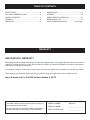
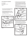
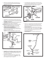
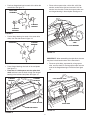
1
Owner's Manual ® 32" SPIKER SPREADER Model No. 486.24331 CAUTION: Before using this product, read this manual and follow all Safety Rules and Operating Instructions. STOP DO NOT RETURN TO STORE For Missing Parts or Assembly Questions Call 1-866-576-8388 • • • • • Safety Assembly Operation Maintenance Parts Sears, Roebuck and Co., Hoffman Estates, IL 60179 U.S.A. www.sears.com/craftsman PRINTED IN U.S.A. FORM NO. 48070 (REV. 5/20/08) TABLE OF CONTENTS SAFETY RULES........................................................... 3 FULL SIZE HARDWARE CHART................................. 4 CARTON CONTENTS.................................................. 5 ASSEMBLY................................................................... 5 OPERATION............................................................... 12 MAINTENANCE......................................................... 13 STORAGE.................................................................. 13 REPAIR PARTS ILLUSTRATION............................... 14 REPAIR PARTS LIST................................................. 15 PARTS ORDERING/SERVICE......................Back Page WARRANTY ONE YEAR FULL WARRANTY When operated and maintained according to the instructions supplied with it, if this Spiker Spreader fails due to a defect in material or workmanship within one year from the date of purchase, call 1-800-4-MY-HOME® to arrange for free repair (or replacement if repair proves impossible). If this product is used for commercial or rental purposes, this warranty applies for only 90 days from the date of purchase. This warranty gives you specific legal rights, and you may also have other rights which vary from state to state. Sears, Roebuck and Co., D817WA, Hoffman Estates, IL 60179 The model number and serial numbers will be found on a decal attached to the hitch tube. You should record both the serial number and the date of purchase and keep in a safe place for future reference. 2 MODEL NUMBER: 486.24331 SERIAL NUMBER: __________________ DATE OF PURCHASE: __________________ SAFETY Any power equipment can cause injury if operated improperly or if the user does not understand how to operate the equipment. Exercise caution at all times, when using power equipment. • Read this owner's manual before attempting to assemble or operate the spiker/spreader. • Wear eye and hand protection when handling and using lawn chemicals. • Read the towing vehicle owner's manual and know how to operate the tractor before using the spiker/spreader attachment. • Always begin with the transmission in first (low) gear and gradually increase speed as conditions permit. Maximum towing speed - 10 M.P.H. • Do not allow anyone to ride on or sit on the spiker/spreader. • Do not drive too close to a creek or ditch and be alert for holes and other hazards which could cause you to loose control of the tractor and spiker/spreader. • Never allow children to operate the tractor or spiker/spreader attachment. • • Do not allow adults to operate the tractor or spiker/spreader without proper instructions. Before operating the vehicle on any grade (hill) refer to the safety rules in the vehicle owner's manual concerning safe operation on slopes. Stay off steep slopes! • Read the chemical label for instructions and cautions for handling and applying chemicals. • Follow maintenance and lubrication instructions as outlined in this manual. Look for this symbol to point out important safety precautions. It means — Attention!! Become alert!! Your safety is involved. 3 HARDWARE PACKAGE CONTENTS SHOWN FULL SIZE A C B D E H G F J T U S O I Q K L P R M V N NOT SHOWN FULL SIZE GG DD W X Z Y FF CC AA REF. QTY. A 2 B 3 C 2 D 2 E 2 F 1 G 1 H 1 I 1 J 2 K 6 L 10 M 2 N 2 O 2 P 2 Q 4 R 4 HH EE II BB DESCRIPTION Hex Bolt, 1/2" x 4" Hex Bolt, 5/16" x 2-1/4" Hex Bolt, 5/16" x 2" Hex Bolt, 5/16" x 1-3/4" Hex Bolt, 5/16" x 1-1/2" Hex Bolt, 5/16" x 1" Hex Bolt, 1/4" x 1 1/4" Hex Bolt, 1/4" x 3/4" Carriage Bolt. 5/16" x 1-3/4" Self-Tapping Screw Nylock Hex Nut, 1/4" Nylock Hex Nut, 5/16" Jam Hex Nut, 1/2" Nylock Jam Hex Nut, 1/2" Flat Washer, 1/4" Nylon Washer, 21/64" Flat Washer, 5/16" Flat Washer, 1/2" REF. QTY. S 10 T 3 U 1 V 1 W 1 X 13 Y 1 Z 1 AA 2 BB 5 CC 1 DD 1 EE 1 FF 1 GG 1 HH 1 II 1 4 DESCRIPTION Flat Washer, 5/8" Cotter Pin, 1/8" x 1-1/2" Cotter Pin, 3/32" x 3/4" Hair Cotter Pin, 1/8" Chain with Connector Flanged Bearing Compression Spring 1/4" Thick Spacer Short Spacer Tube Long Spacer Tube Flow Control Link Ferrule Control Lever Grip Height Adjustment Grip Plastic Wing Nut Flat Head Hitch Pin, 3/8" Flow Plate Spring ASSEMBLY CARTON CONTENTS 1. 2. 3. 4. 5. 6. 7. 8. Chain Cover Flow Control Lever Center Brace Hopper Assembly Hitch Tube (2) Lift Handle Spike Disk (7) Drive Disk Assembly (2) 2 9. Wheel (2) 10. Transport Tube Assembly 11. Hitch Bracket (2) 12. Spiker Shaft Assembly 4 3 1 5 10 6 7 9 11 8 5 12 TOOLS REQUIRED FOR ASSEMBLY • • (2) 7/16" Wrenches (2) 1/2" Wrenches (2) 3/4" or Adjustable Wrenches (1) Screwdriver (1) Pliers • • • • Assemble the grip onto the lift handle. See figure 2. On the right side, insert a 5/16" x 1-3/4" hex bolt through a 5/16" flat washer and then through the rear hole in the hopper and the hitch tube. Assemble the transport tube and then the lift handle onto the bolt and secure with a 5/16" nylock hex nut. Do not tighten yet. See figure 2. Assemble a 5/16" x 1" hex bolt and 5/16" nylock hex nut to the bottom hole in the transport tube assembly and the lift handle. Do not tighten yet. See figure 2. LIFT HANDLE Remove all parts and hardware packages from the carton. Lay out all parts and hardware and identify using the illustrations on pages 3 and 4. 5/16"FLAT WASHER GRIP 5/16" x 1-3/4" HEX BOLT Attach a hitch tube to the front hole in the right hand side of the hopper using a 5/16" x 1-1/2" hex bolt, a 5/16" flat washer and a 5/16" nylock hex nut. Assemble the bolt and washer from inside the hopper. Do not tighten yet. See figure 1. 5/16" x 1" HEX BOLT Repeat on the left hand side of the hopper. 5/16" FLAT WASHER 5/16" 1-1/2" HEX BOLT 5/16" NYLOCK HEX NUT TRANSPORT TUBE FIGURE 2 • On the left side, insert a 5/16" x 1-3/4" hex bolt through a 5/16" flat washer and then through the rear hole in the hopper and the hitch tube. Assemble the transport tube onto the bolt and secure it with a 5/16" nylock hex nut. Do not tighten yet. See figure 3. 5/16" x 1-3/4" HEX BOLT HITCH TUBE 5/16" NYLOCK HEX NUT FIGURE 1 6 FIGURE 3 5/16"FLAT WASHER 5/16" NYLOCK HEX NUT • Fasten the hitch tubes together using three 5/16" x 2-1/4" hex bolts and 5/16" nylock hex nuts. Do not tighten yet. See figure 4. • • 5/16" NYLOCK HEX NUT (3) If the wheel does not spin freely, back off the nylock jam nut and then the plain jam nut 1/4 to 1/2 turn each. Assemble a wheel to the other side. See figure 6. TRANSPORT TUBE 1/2" FLAT WASHER 5/16" x 2-1/4" HEX BOLT (3) 1/2" NYLOCK HEX JAM NUT FIGURE 4 1/2" x 4" HEX BOLT • Assemble the hitch brackets to the hitch tubes using two 5/16" x 2" hex bolts and 5/16" nylock hex nuts. Do not tighten. See figure 5. • Assemble the hitch pin through the hitch brackets and secure with the hair cotter pin. See figure 5. IMPORTANT: Do not collapse the flat ends of the hitch tubes when tightening the bolts in the next step. • Tighten, but do not overtighten the two 5/16" x 1-1/2" hex bolts assembled in figure 1. Tighten, but do not overtighten the two 5/16" x 1-3/4" hex bolts assembled in figures 2 and 3. The lift handle must be able to pivot. Tighten the hex bolts assembled in figure 4 and 5. 1/2" HEX JAM NUT FIGURE 6 • • • Screw a 1/4" nylock hex nut all the way onto the flow control link. Assemble the ferrule onto the link and then start a 1/4" nylock hex nut one or two turns onto the link. See figure 7. Assemble the ferrule into the hole at the end of the flow control lever using a 1/4" nylock hex nut. Tighten the nut, leaving it loose enough that the ferrule can pivot freely. See figure 7. Assemble the grip onto the end of the flow control lever. See figure 7. 5/16" x 2" HEX BOLT (2) GRIP HITCH PIN FLOW CONTROL LEVER HAIR COTTER PIN (1/8") 1/4" NYLOCK HEX NUT 5/16" NYLOCK HEX NUT (2) FIGURE 5 • • FERRULE Assemble a 1/2" flat washer, a wheel, another 1/2" flat washer and then a 1/2" jam nut onto a 1/2" x 4" hex bolt. Tighten the nut finger tight and then back off 1/4 to 1/2 turn. See figure 6. Assemble the bolt and wheel to the transport tube using a 1/2" nylock hex jam nut. Tighten the nut but don't collapse the tube. See figure 6. FLOW CONTROL LINK FIGURE 7 7 1/4" NYLOCK HEX NUT 1/4" NYLOCK HEX NUT • • • Place the flow control lever into the slot in the hopper. See figure 8. Place the center brace into the hopper. Insert the 1/4" x 1-1/4" hex bolt through the center brace and the front of the hopper. Assemble a 1/4" flat washer, the flow control lever and a 1/4" nylock hex nut onto the bolt. Do not tighten yet. See figure 8. Insert the 1/4" x 3/4" hex bolt through the center brace and the rear of the hopper. Assemble a 1/4" flat washer and 1/4" nylock hex nut onto the bolt. Tighten both the front and rear bolts. See figure 8. • • • • CENTER BRACE 1/4" FLAT WASHER 1/4" x 1-1/4" HEX BOLT 1/4" x 3/4" HEX BOLT • 1/4" HEX LOCK NUT Move the flow control lever as far as it will go to the "OFF" position. Push the feed plate back as far as it will go to the closed position. See figure 10. Place a nylon washer onto the bent end of the flow control link and then insert the link into the feed plate bracket. Secure it with a 3/32" x 3/4" cotter pin. See figure 10. Tighten the lower 1/4" nylock hex nut until it touches the bottom of the ferrule, then tighten the upper 1/4" nylock hex nut until it is snug against the top of the ferrule. See figure 10. Hook the open end of the spring into the feed plate. Place the closed end of the spring onto the end of the hex bolt in the flow control lever. Secure it with a 1/4" nylock hex nut. See figure 10. Open and close the feed plate using the flow control lever. Check to make sure the feed plate is closed completely when the lever is in the "OFF" position. If the feed plate does not close completely, adjust the 1/4" nylock hex nuts on the flow control link. See figure 10. FLOW CONTROL LEVER 1/4" FLAT WASHER 1/4" NYLOCK HEX NUT 1/4" NYLOCK HEX NUT EXTENSION SPRING FIGURE 8 • • 1/4" NYLOCK HEX NUT Insert the 5/16" x 1-3/4" carriage bolt up through the slot and secure it with a nylon washer and the plastic wing nut. See figure 9. Move the lift handle into the locked position as shown in figure 9 and then tip the spreader back to rest on the wheels and the rear of the hopper. PLASTIC WING NUT 1/4" NYLOCK HEX NUT FLOW CONTROL LINK FEED PLATE NYLON WASHER 3/32" x 3/4" COTTER PIN NYLON WASHER FIGURE 10 5/16" x 1-3/4" CARRIAGE BOLT LOCKED POSITION FIGURE 9 8 • Push two flange bearings into each of the drive disk assemblies. See figure 11. • DRIVE DISK ASSEMBLY Place a short spacer tube, a drive disk, a 5/8" flat washer, another drive disk and a second 5/8" flat washer onto the shaft. Fit the short spacer tube onto the flanged bearing in the end plate. See figure 14. DRIVE DISKS FLANGED BEARING FLANGED BEARING FIGURE 11 • Push a flange bearing into each of the seven drive disks, from the side shown in figure 12. SPIKE DISK SHORT SPACER TUBE FLANGED BEARING 5/8" FLAT WASHER FIGURE 14 IMPORTANT: When assembling the spike disks, be sure they face in the direction shown in the instructions. FIGURE 12 • • • Press flanged bearings into both of the end plates. See figure 13. Place the 1/4" thick spacer onto the spike disk shaft and then insert the shaft through the flanged bearing in the left hand end plate. See figure 13. FLANGED BEARING FLANGED BEARING Place two spike disks, separated by a long spacer tube, onto the shaft. Fit the long spacer tube onto the ends of the flanged bearings in the disks. See figure 15. LONG SPACER TUBE 1/4" THICK SPACER SPIKE DISK SPIKE DISK SHAFT FIGURE 15 FIGURE 13 9 • • Place a 5/8" flat washer, the compression spring and another 5/8" flat washer onto the shaft. See figure 16. Place two 5/8" flat washers separated by a long spacer tube onto the shaft. See figure 18. 5/8" FLAT WASHER LONG SPACER TUBE COMPRESSION SPRING 5/8" FLAT WASHER FIGURE 16 FIGURE 18 • • Place two spike disks, separated by a long spacer tube, onto the shaft. Fit the long spacer tube onto the ends of the flanged bearings in the disks. See figure 17. Place two spike disks, separated by a long spacer tube, onto the shaft. Fit the long spacer tube onto the ends of the flanged bearings in the disks. See figure 19. LONG SPACER TUBE LONG SPACER TUBE SPIKE DISK SPIKE DISK FIGURE 17 FIGURE 19 10 • • Place two 5/8" flat washers separated by a long spacer tube onto the shaft. See figure 20. • Place a 5/8" flat washer onto the end of the spike disk shaft and secure the shaft with a 1/8" x 1-1/2" cotter pin. See figure 22. Fasten the two drive disks to the shaft using two 1/8" x 1-1/2" cotter pins. See figure 22. 1/8" x 1-1/2" COTTER PIN LONG SPACER TUBE DRIVE DISKS 5/8" FLAT WASHER FIGURE 20 5/8" FLAT WASHER • FIGURE 22 Place a spike disk and a short spacer tube onto the shaft. Fit the short spacer tube onto the ends of the flanged bearings in the spike disk and in the end plate. Push the shaft on through the flanged bearing in the end plate. See figure 21. • • Assemble the chain onto the two sprockets on the left side of the hopper. Fasten the ends of the chain together using the connecting link. See figure 23. Place the chain cover over the chain and fasten it to the hopper end plate using two self tapping screws. See figure 23. SELF TAPPING SCREW CHAIN CONNECTING LINK SPIKE DISK SHORT SPACER TUBE FIGURE 21 FIGURE 23 11 OPERATION KNOW YOUR SPIKER SPREADER Read this owner's manual and safety rules before operating your Spiker Spreader. Compare the illustration below with your Spiker Spreader to familiarize yourself with the various controls and their locations. FLOW CONTROL LEVER PLASTIC WING NUT LIFT HANDLE FLOW CONTROL LEVER Opens and closes the flow plate at the bottom of the hopper. PLASTIC WING NUT Tightens at desired setting to control how far the flow control lever can open the flow plate. LIFT HANDLE Raises the unit for transport or lowers it for spreading and aerating. HOW TO USE YOUR SPIKER/SPREADER • • • • • Refer to the instruction label on the material package and to the instruction decal on your spreader to help determine the proper spreader setting and application rate. Also see the Setting Chart on page 13 of this manual for a general range of settings for commonly used materials. Determine the approximate square footage of the area to be covered and estimate the amount of fertilizer or seed required. Move the spreader to the area where application is to begin. ALIGN AND TIGHTEN WING NUT AT DESIRED FLOW SETTING 0 1 2 3 4 5 6 7 8 9 10 12 13 11 14 15 • • • • • 18 16 17 • OFF IMPORTANT: Always place flow control lever in the "OFF" position to prevent excess fertilizer from being released when filling the spreader and when stopping or turning. WING NUT SET AT "5" FIGURE 24 Loosen the plastic wing nut and move it to the desired setting. Retighten the nut. See figure 24. Making sure the flow control lever is in the "OFF" position, fill the hopper, breaking up any lumps. Lower the aerator spikes to the operating position. Start the spreader in motion and then move the flow control lever to the "ON" position (against the plastic wing nut) as you travel across your lawn. The recommended towing speed is 3 m.p.h. Do not make sharp turns with spikes in the ground. Raise aerator spikes to transport position when crossing over concrete or other hard surfaces. Do not aerate if the ground is extremely hard or dry. If ground is too dry, sprinkle or water for one to two hours prior to use. Do not aerate if the ground is too wet (muddy). 12 SETTING CHART • MATERIAL Flow Rate Setting TYPE At 3 M.P.H. Fertilizer Granular / Pelleted 5-6 / 6-7 Grass Seed Fine / Coarse 5-6 / 7-8 • • 3 M.P.H. is equivalent to traveling 100 feet in 23 seconds. For easiest application, first apply material across both ends of the area. Two or three passes on each end are sufficient. Then apply material back and forth as shown. Use the end areas for turning around, shutting off the spreader as you enter the end areas and turning the spreader on again as your leave the end areas for your next pass. See figure 25. If lawn is odd shaped, spread a border around the edges and then spread between the border. Be careful when spreading around ornamental plants because weed control chemicals can damage these plants. OPERATING TIPS • To help prevent granular material from compacting and clogging the hopper, avoid unnecessary towing when the hopper flow plates are closed. • Reduce the flow setting for speeds slower than 3 M.P.H. and increase the setting for higher speeds. • To avoid misses or striping, overlap the previous wheel tracks by approximately 5" to 6". FIGURE 25 MAINTENANCE CUSTOMER RESPONSIBILITIES • Read and follow the maintenance schedule and the maintenance procedures listed in this section. MAINTENANCE SCHEDULE Fill in dates as you complete regular service. Check for loose fasteners Lubrication Cleaning se e e h u h us ar orag c t a e c s e e ea y y e for ter ver efor E Be Af B Service Dates X X X LUBRICATION Spike points are sharp. Exercise caution when handling or working near spike disks. • • CLEANING CHECK FOR LOOSE FASTENERS • Apply a few drops of oil to wheels and to plastic bearings in spike disks and at end of spike axle. Remove chain cover, clean and oil drive chain. • Before each use make a thorough visual check of the spiker spreader for any bolts and nuts which may have loosened. Retighten any loose bolts and nuts. • Always empty spiker spreader after each use, storing leftover material in it's original bag. Wash the spiker spreader and dry thoroughly after each use. STORAGE • • Empty the spiker spreader, storing leftover material in it's original bag. Apply a light coat of oil on exposed metal to help prevent rust. • • 13 Wash the spiker spreader and dry thoroughly before storing. Store in a clean, dry area. B 42 23 2 14 59 A 7 35 58 1 62 C 10 45 38 44 57 26 A 46 12 59 25 50 5 13 33 41 43 43 44 55 58 58 61 11 63 37 43 9 19 59 54 12 47 59 56 29 53 54 52 16 4 8 6 28 43 42 34 43 60 31 8 3 B F 48 13 20 32 39 59 24 14 13 21 10 59 40 30 58 15 22 17 57 C 42 23 42 18 36 51 27 49 PARTS REPAIR PARTS FOR MODEL 486.24331 PART NO. DESCRIPTION REF. NO. PART NO. DESCRIPTION Ferrule, 5/16" Thread x 1/4" Hole Bolt, Hex 5/16" x 2-1/4" Bolt, Hex 5/16" x 2" Bolt, Hex 5/16" x 1-1/2" Bolt, Hex 5/16" x 1-3/4" Bolt, Hex 5/16" x 1" Screw, Self Tapping 1/4" x 1" Bolt, Hex 1/4-20 x 3/4" Nut, Nylock Hex 5/16" Nut, Nylock Hex 1/4" Washer, Flat 1/4" Washer, Flat 5/16" Bolt, Hex 1/2" x 4" Full Thread Nut, Hex Jam 1/2" Nut, Nylock Hex Jam 1/2" Pin, Hair Cotter #4 (1/8") Pin, Cotter 3/32" x 3/4" Pin, Flat Head Hitch, 3/8" Dia. Bolt, Carriage 5/16" x 1-3/4" Nut, Plastic Wing 5/16" Washer, Nylon 21/64" Spacer Tube, Long Spring, Compression Spacer Tube, Short Bearing, Flanged PV80 .63 I.D. Washer, Flat 5/8" (21/32" x 1-1/4") Bolt, Hex 1/4-20 x 1-1/4" Washer, 13/16" x 1-1/2" x 1/16" Push Nut, 1/2" Washer, Flat .518 x 1 x.02 Owner's Manual QTY Hopper 34 47969 1 End plate, Right Hand 35 43224 3 End plate, Left Hand 36 44180 2 Rivet, Pop 37 43085 2 Brace, Center 38 43084 2 Assembly, Agitator Shaft 39 43063 1 Bearing, Hex Flange 40 44731 2 Blade, Agitator 41 43012 1 Screw, Hex Washer Hd, #8-32 42 47810 10 Washer, 17/32" x 1-1/2" x 10 Ga. 43 47189 6 Spacer, .8" I.D.x1" O.D. x .50" Lg. 44 43088 2 Washer, 17/32" x 1" x 16 Ga. 45 43081 4 Pin, Cotter 1/8" x 1-1/2" 46 45100 2 Spacer, .5" I.D. x 1" O.D. x .59" Lg. 47 43019 2 Spacer, .66" I.D.x1.25" O.D. x .25" 48 48115 2 Spring, Flow Plate 49 43343 1 Assembly, Spiker Shaft 50 44101 1 Assembly, Transport Tube 51 47623 1 Lever, Flow Control 52 44215 1 Drive Disk 53 712-0421 1 Disk, Spike (7") 54 1543-69 2 Cover, Chain 55 46524 5 Tube, Hitch 56 47777 1 Lift, Handle 57 46497 2 Wheel, 10" x 1-5/8" 58 741-0249 13 Plate, Flow 59 R19212016 10 Bracket, Hitch 60 1509-90 1 Bracket, Feed Plate 61 48173 2 Rivet, Pop 5/32 (Stainless) 62 46557 1 Chain with Connector 63 44137 5 Grip, Control Arm .187" x .75" 48070 1 Grip, Height Adjustment 32"/38" Link, Flow Control QTY 1 47931 1 2 24736 1 3 24735 1 4 48418 12 5 24747 1 6 64104 1 7 47963 2 8 24739 2 9 47978 10 10 R19172410 2 11 46838 2 12 R19171616 4 13 43093 3 14 45133 1 15 23520 1 16 47962 1 17 64106 1 18 64107 1 19 24743 1 20 63956 2 21 24332 7 22 47953 1 23 47944 2 24 24746 1 25 47961 2 26 24741 1 27 23981 2 28 24539 1 29 728-3001 2 30 47960 1 31 43848 1 32 43943 1 33 47959 1 NO. REF. REPAIR PARTS FOR MODEL 486.24331 15 Get it fixed, at your home or ours! Your Home For repair – in your home – of all major brand appliances, lawn and garden equipment, or heating and cooling systems, no matter who made it, no matter who sold it! For the replacement parts, accessories and owner’s manuals that you need to do-it-yourself. For Sears professional installation of home appliances and items like garage door openers and water heaters. 1-800-4-MY-HOME® (1-800-469-4663) Call anytime, day or night (U.S.A. and Canada) www.sears.com www.sears.ca For expert home solutions advice: www.managemyhome.com Our Home For repair of carry-in items like vacuums, lawn equipment, and electronics, call or go on-line for the location of your nearest Sears Parts & Repair Service Center 1-800-488-1222 (U.S.A.) 1-800-469-4663 (Canada) Call anytime, day or night www.sears.com www.sears.ca To purchase a protection agreement on a product serviced by Sears: 1-800-827-6655 (U.S.A.) 1-800-361-6665 (Canada) Para pedir servicio de reparación a domicilio, y para ordenar piezas: Au Canada pour service en français: 1-888-SU-HOGAR® 1-800-LE-FOYER MC (1-888-784-6427) ® Registered Trademark / TM Trademark / SM Service Mark of Sears Brands, LLC ® Marca Registrada / TM Marca de Fábrica / SM Marca de Servicio de Sears Brands, LLC MC Marque de commerce / MD Marque déposée de Sears Brands, LLC (1-800-533-6937) www.sears.ca © Sears Brands, LLC