1
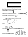
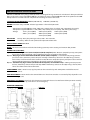
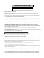
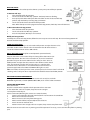
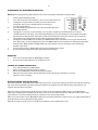
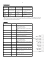
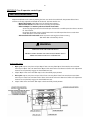
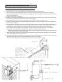
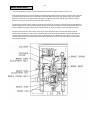
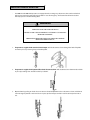
INSTALLATION AND INSTRUCTION MANUAL
MODELS: PRO-GH, PRO-GHC
AUG, 2010
2
TABLE OF CONTENTS
PAGE:
VERIFICATION OF OPERATOR AND HARDWARE __________________________________
3
SPECIFICATIONS ______________________________________________________________
4
SAFETY INSTRUCTIONS ________________________________________________________
5
INSTALLATION________________________________________________________________
6
ELECTRICAL CONNECTIONS AND SETTINGS_______________________________________
9
LIMIT SWITCH ADJUSTMENT ___________________________________________________
23
MICANAN PHOTOBEAM INSTALLATION INSTRUCTIONS____________________________
24
CLUTCH ADJUSTMENT_________________________________________________________
27
FIRE RELEASE INSTALLATION___________________________________________________
28
BRAKE ADJUSTMENT__________________________________________________________
29
EMERGENCY MANUAL OPERATION _____________________________________________
30
OPERATOR MAINTENANCE ____________________________________________________
31
MECHANICAL DRAWINGS AND PARTS LISTS _____________________________________
32
ELECTRICAL DIAGRAMS _______________________________________________________
36
WARRANTY ________________________________________________________________
45
OPTIONS
MP00046
MW00024
MW00025
PRO-_W
PRO-_4X
PRO-_X
MP00007 *
MK00061 **
MP00001 **
PRO-PL
MP00038
MP00037
9999999
MP00069-74
MP00112-118
MX00001
MW00050,52
#60, #80 Drive Chain and Sprockets
Chain Spreader 1” – 1”
Chain Spreader 1” – 1-1/4”
Waterproof modification
Corrosion proof modification
Explosion proof modification
115 Volt control circuit
1.5 sec time delay on reverse
Timer to Close
Separate control panel
Fire release mechanism
Hand Crank
Pusher Springs
Auxiliary trolley c/w track & #41 chain
Dual auxiliary trolley c/w track & #41 chain
Floor Level disconnect in lieu of chain keeper
In-Line Torque Clutch
* Not available for logic board controls
** Standard feature with logic board controls
WARNING
DO NOT CONNECT TO ELECTRICAL
POWER DURING INSTALLATION
OR SERVICING OF OPERATOR
3
IMPORTANT
FOR ANY QUESTIONS CONCERNING THE SAFETY OR OPERATION OF THIS
OPERATOR PLEASE CONTACT MICANAN SYSTEMS AT 1-877-888-1116
SAVE THESE INSTRUCTIONS
VERIFICATION OF OPERATOR AND HARDWARE
Upon delivery of your MICANAN SYSTEMS heavy-duty gearhead jackshaft door operator, please inspect the unit carefully for
damage. Verify that operator horsepower, voltage, phase and amperage correspond to available power supply and door
application. Check that along with your operator you have received the following standard hardware.
1 x OPEN/CLOSE/STOP 3-button control station:
1 x #50 Drive chain package : 4’ (1.2m) or 5’ (1.5m) c/w #50 connecting link
1 x Drive Sprocket 50B12 or 50B15 c/w 2 set screws and keyway
1 x Door Sprocket: 50B23 x 1” or 1-1/4” bore, 2 set screws and ¼” x 1-1/4” keyway for sectional doors
or 50B40 x 1” or 1-1/4” bore, 2 set screws and ¼” x 1-1/4” keyway for rolling doors
Note: Sprocket size and bore may vary according to door
size and type, shaft size and drum diameter
1 x Chain keeper
1 x Keyring
4 x 3/8” bolt, hex nut, lock washer and flat washer
1 x pocket wheel hand chain (2 x door height less 4’ (1.2m))
1 x Warning sign
1 set of Micanan photocells (supplied when operator ordered
with interface module or logic control
4
PRO-GH & PRO-GHC SPECIFICATIONS
PRO-GH and PRO-GHC heavy-duty jackshaft operators are designed for large commercial and industrial doors provided that
doors are driven by a drive shaft. Model PRO-GH is essentially the same as model PRO-GHC with the exception that the PROGHC operator has a reinforced frame and pillow block bearings on reducer drive shaft.
STANDARD OPERATOR WEIGHT: PRO-GH (100-120 Lbs.)
PRO-GHC (120-150 Lbs.)
MOTOR: Continuous duty 1725 RPM industrial type motor. Full overload protection.
- Horsepower range for PRO-GH: 1/2HP, 3/4HP, 1HP, 1.5HP (3-phase & 1-phase), 2HP , 3HP, 5HP (3-phase only)
- Horsepower range for PRO-GHC: 1/2HP, 3/4HP, 1HP, 1.5HP (3-phase & 1-phase), 2HP, 3HP (3-phase only)
- Voltage:
115V 1-phase (60Hz)
230V 3-phase (60 Hz)
220V 1-phase (50Hz)
230V 1-phase (60Hz)
460V 3-phase (60Hz)
380V 3-phase (50Hz)
575V 3-phase (60Hz)
REDUCTION:
Primary: Heavy duty worm gear reducer 40:1 – 44:1 reduction
Secondary: #50 chain and sprockets from operator to door shaft
OUTPUT SHAFT SPEED: 40-43 RPM
BRAKE : Solenoid actuated drum and brake shoe braking system to prevent coasting and maintain door position.
WIRING TYPE (3 OPTIONS):
Option 1: Full Feature logic board Smart 10.0 (UL325 (2010) compliant). Note: Micanan compatible primary entrapment
device must be connected for B2, T or TS (momentary or timer activation on close) feature.
Option 2: Relay logic controls with Interface Module (UL325 (2010) compliant). C2 Standard factory wiring (constant
pressure on close, momentary contact on open and stop). If momentary contact on close (B2) wiring is desired,
move “white” wire from terminal #6 to terminal #3. Note: Micanan compatible primary entrapment device must be
connected for B2 (momentary activation on close) or for T (timer to close) feature.
Option 3: Standard relay logic controls (not UL325 2010 compliant, not available in US) C-2 Wiring constant pressure
on close, momentary contact on open and stop. NOTE: If momentary contact on close (B2) wiring is desired, move
“white” wire from terminal #5 to terminal #3.
TRANSFORMER: 24VAC control circuit, supplies power to drive control relays with 15VA power available for external
devices.
LIMIT ADJUSTMENT: 4 micro switches that control door travel. These limit switches are activated by fully adjustable screw
type cams.
EMERGENCY DISCONNECT: Floor level cable disconnect system with electrical cut-out feature allows person to manually
operate door by chain hoist in case of emergency.
OPERATOR DIMENSIONS:
PRO-GH
PRO-GHC
5
IMPORTANT SAFETY INSTRUCTIONS
WARNING
TO REDUCE THE RISK OF INJURY OR POSSIBLE DEATH
-
READ AND FOLLOW ALL INSTRUCTIONS
-
Never allow children to operate or play with door controls. Keep the remote control (where provided) away from
children.
-
Personnel should keep away from a door in motion and keep the moving door in sight until it is completely closed or
opened. NO ONE SHOULD CROSS THE PATH OF A MOVING DOOR.
-
Test the door’s safety features at least once a month. After adjusting the limit of travel, retest the door operator’s safety
features. Failure to adjust the operator properly may cause severe injury or death.
-
For products having a manual release, if possible, use the manual release only when the door is closed. Use caution
when using this release when the door is open. Weak or broken springs may cause the door to fall rapidly, causing
severe injury or death.
-
KEEP DOORS PROPERLY OPERATING AND BALANCED. See Door Manufacturer’s Owner’s Manual. An improperly
operating or balanced door could cause severe injury or death. Have trained door systems technician make repairs to
cables, spring assemblies, and other hardware.
-
Press the “OPEN” device or use emergency disconnect mechanism if a person is trapped under the door.
-
SAVE THESE INSTRUCTIONS. The owner or users must understand the safety and operation of door system. Insure that
this installation manual be located close to the door system.
IMPORTANT INSTALLATION INSTRUCTIONS
-
READ AND FOLLOW ALL INSTALLATION INSTRUCTIONS
-
Commercial door operators are never to be installed on a residential installation
-
Install only on a properly operating and balanced door. A door that is operating improperly could cause severe injury. Have qualified
service personnel make repairs to cables, spring assemblies, and other hardware before installing the operator.
-
Remove all pull ropes and remove, or make inoperative, all locks (unless mechanically and/or electrically interlocked to the power
unit) that are connected to the door before installing the operator.
-
Install the door operator at least 8 feet or more above the floor if the operator has exposed moving parts.
-
Do not connect the operator to the source of power until instructed to do so.
-
Locate the control station: (a) within sight of the door, (b) at a minimum height of 5 feet so that small children cannot reach it, and (c)
away from all moving parts of the door.
-
Install the Entrapment Warning Placard next to the control station in a prominent location.
-
For products having a manual release, instruct the end user on the operation of the manual release.
-
Install non-contact entrapment protection devices (photocells) and/or contact entrapment protection devices (reversing edges).
Note: photocells should be installed at no more than 6” from the floor. Edges should be installed on the leading edge of the door.
6
INSTALLATION INSTRUCTIONS
WARNING
DO NOT INSTALL THIS OPERATOR
BEFORE READING THIS MANUAL CAREFULLY.
Note:
- Installation of operator must be done by a qualified installer. Door must be properly installed and working
smoothly. Remove all door locks prior to installation.
- The PRO-GH, PRO-GHC operators have dual output shafts and may be mounted on right (standard) or left hand
side of door. If handing of operator must be reversed, loosen set screws, remove drive sprocket and keyway and
install on opposite side of drive shaft.
- For both the PRO-GH and PRO-GHC operators the handing of the operator should be stated at time of order.
Depending on installation, if handing of chain hoist is not correct the hand chain may hang in door opening. If this
is the case, swing chain off to the side and hook it over the top of the door jamb. If desired, the pocket wheel,
chain guard and hand chain may be removed on site and installed on opposite side of universal disconnect shaft as
shown below.
7
1.
Install control station away from all moving door parts, within sight of the door and a minimum of 5 ft (1.5 m) from
the ground.
2.
Install entrapment warning sign next to control station.
3.
As a general rule, the door operator should be installed below the drive shaft and as close to the door as possible.
The ideal distance between the operator drive shaft and the door shaft is approximately 12” (30cm) to 15” (38cm).
The operator may be wall/bench mounted or bracket /shelf mounted. These two mounting configurations are
shown below:
4.
Mount the operator to the wall, hood or bench with 3/8” bolts, nuts and washers provided or with lag bolts and
shields if installation requires it. Make sure that operator is secured but do not tighten bolts.
5.
Place door sprocket on door shaft and align with operator drive sprocket but do not insert keyway or set screws.
6.
If an optional chain spreader has been ordered with your operator, install as shown below:
8
7.
Install drive chain over sprockets, cut to a suitable length and connect with connecting link.
8.
Lower or raise operator to adjust chain tension so that there is no more than ¼” chain slack between sprockets.
Tighten operator mounting bolts.
9.
Carefully re-align sprockets, if necessary and secure keyway and set screws.
10.
Install hand chain by wrapping it through chain guard holes and pocket wheel. Allow chain to hang down towards
floor. Cut chain and connect so that chain is 2’ to 3’ from the floor.
11.
Install chain keeper to wall near hand chain at approximately 4’ from floor. Run disconnect chain through keyhole
of chain keeper and cut excess chain links if required. Attach keyring to end of disconnect chain.
12.
If an optional floor level disconnect lever was ordered in lieu of the chain keeper, mount to wall with suitable
hardware. Attach both chains together using keyring provided. Allow disconnect chain to be slightly slack when
lever is in the up position.
13.
After installation is complete, remove red
Activation pin on reducer breather plug.
IMPORTANT
9
ELECTRICAL CONNECTIONS
THERE ARE 3 POSSIBLE ELECTRICAL CONTROL CONFIGURATIONS FOR THIS OPERATOR:
A) Standard relay logic controls (not UL325 2010 compliant, not available in US). Refer to Section A for electrical
connections. Refer to electrical drawings inside your operator control box or generic drawings MS100-WW or
MS300-WW in the electrical drawings section at the end of this manual.
B) Relay logic controls with Interface Module (UL325 (2010) compliant. Refer to Section B for electrical
connections. Refer to electrical drawings inside your operator control box or generic drawings MS100-IM-WW or
MS300-IM-WW in the electrical drawings section at the end of this manual.
C) Full Feature logic board Smart 10.0 (UL325 (2010) compliant). Refer to Section C for electrical
Connections and logic board instructions. Refer to electrical drawings inside your operator control box or generic
drawings MSL100-110V-WW, MSL100-220V-WW, MSLC100-WW, MSL300-WW or MSLC300-WW in the
electrical drawings section at the end of this manual.
IMPORTANT
-
MICANAN HIGHLY RECOMMENDS THAT EACH INDIVIDUAL COMMERCIAL
DOOR OPERATOR HAVE IT’S OWN DEDICATED POWER SUPPLY
-
MICANAN HIGHLY RECOMMENDS THAT EACH INDIVIDUAL COMMERCIAL
DOOR OPERATOR HAVE AN EXTERNAL CIRCUIT BREAKER OR FUSED
DISCONNECT
WARNING
COMPARE AVAILABLE POWER SUPPLY VOLTAGE TO OPERATOR NAMEPLATE PRIOR TO ELECTRICAL
CONNECTION. FAILURE TO CONNECT APPROPRIATE POWER SUPPLY VOLTAGE MAY CAUSE SERIOUS
DAMAGE TO OPERATOR.
Refer to electrical diagrams inside control box cover or at the end of this manual prior to connection of power supply or
control station.
WARNING
TO REDUCE THE RISK OF INJURY OR DEATH:
ALL ELECTRICAL CONNECTIONS SHOULD BE MADE BY A QUALIFIED SERVICE PERSON
DO NOT ATTEMPT TO MAKE ELECTRICAL CONNECTIONS TO OPERATOR UNLESS POWER SUPPLY HAS
BEEN DISCONNECTED AT FUSE BOX
OPERATOR MUST BE CONNECTED IN ACCORDANCE TO LOCAL ELECTRICAL CODES AND GROUNDED
TO GREEN GROUND LUG LOCATED INSIDE CONTROL BOX
10
SECTION A: PRO-GH, PRO-GHC Standard relay logic controls (not UL325 2010
compliant, not available in US)
CONNECTION OF POWER SUPPLY AND CONTROL STATION
POWER WIRING: Use 1-1/8” (2.85 cm) diameter holes for all power wiring.
1.
2.
Single phase: Connect single phase power supply to terminals L/L1 (line) and N/L2 on three-pole
power terminal strip.
Three-phase: Connect three phase power supply to terminals L1, L2 and L3 on three-pole power
terminal strip.
CONTROL WIRING: Use 7/8” (2.22 cm) diameter holes for all control wiring.
Note: Do not run control wires and power wires in same conduit.
- Install control station within clear sight of door but away from all moving parts of door or hardware.
Install Entrapment warning sign next to control station. Connect 3-button (open/close/stop) push button
station to terminals 2, 3, 4 and 5. Refer to electrical diagram for connection of two 3-button stations.
NOTE: After electrical connections are made, manually move door to mid-position and, using the control station press the
“Open” button for several seconds and then press the “Stop” button. If door did not move in correct direction verify
wiring control station. For 3-phase operators, if door still moves in wrong direction reverse any two of the three
incoming power supply leads to correct rotation.
LIMIT SWITCH ADJUSTMENT
- Adjust Limit switches as explained in the “Limit switch adjustment section” further in this manual.
11
CONNECTION OF A REVERSING EDGE DEVICE AND CONTROL ACCESSORIES
1.
2.
Reversing Edge device (must be normally open contact):
Note: If the door is controlled by any device or wired in such a manner that the door is not controlled by constant
pressure on close then an appropriate reversing edge must be installed.
External interlock: Remove jumper between terminals 1 and 2 and wire interlock between these two
terminals.
3.
Radio control receiver: Wire standard radio receiver to separate radio strip on side of control box or to terminals 7, 8
and 9 on control terminal strip inside control box.
4.
Single button open/close device: Wire to terminals 7 and 8 on control terminal strip.
5.
Loop detectors, standard photocells (with a N.O. contact) and other reversing devices: Wire to terminals 3 and 6
on control terminal strip. IMPORTANT: PHOTOCELLS MUST BE MOUNTED NO HIGHER THAN 6” OFF THE FLOOR.
6.
24 Volt power: Wire to terminals 1 and 9 on control terminal strip
12
SECTION B: PRO-GH(M), PRO-GHC(M) Relay logic controls with Interface
Module (UL325 2010 compliant)
Operator electrical connections and start-up instructions
NOTE: THIS OPERATOR COMES WITH AN INTERFACE MODULE INTEGRATED INTO THE CONTROL CIRCUIT.
THE PURPOSE OF THE INTERFACE MODULE IS TO ALLOW FOR FAILSAFE MONITORING OF A MICANAN
COMPATIBLE SAFETY DEVICE AS PER UL 325 (2010) REQUIREMENTS.
Important: Follow these steps carefully and in the order shown
1) Connect Power supply:
Single phase: Connect single phase power supply to terminals L/L1 and N/L2 on the 3-pole power terminals strip.
3-phase: Connect 3-phase power supply to terminals L1, L2 and L3 on the 3-pole power terminal strip.
2) Connect Push-button station for installation purposes (single phase or 3-phase):
Connect open/close/stop push button station to terminals T2 (stop), T3 (common), T4 (open) and T6 (temporary CP on
close).
3) Verify motor direction:
After the electrical power connections are made and push button station is connected, manually move the door to midposition. Press Close button for several seconds and then press stop button. If door did not move in correct direction (or if
limit cams not moving in correct direction towards the close limit switch) see below:
13
Single phase operators: The operators leave the factory with correct motor and limit shaft direction according to standard
door installations. However, for special fire door, thru- wall mounting or other special door applications, the motor direction
and limit switch direction may need to be reversed. To reverse the motor rotation, interchange black and white wires going
to motor on the reversing contactor.
3-phase operators: If door moves in wrong direction, turn off incoming power and reverse any two of the three incoming
power supply leads to correct rotation. Press the open button and then activate the open limit to ensure door stops. If door
does not stop, interchange grey and red wires on open and close limits. Interchange white and grey wires on advanced
open and advanced close limits. Remove blue wire from advanced open limit and place it on N.O pin of advanced close
limit.
4) Adjust limit switch cams:
Using the open/close/stop push button station move door to fully closed and fully open oppositions and set limit cams to
correct position. (See Limit adjustment section D further in this manual for complete detail on the end of travel limit
adjustments).
5) Activate Interface module:
After adjusting the open and close limits and verifying the motor rotation, open the door to the full-open position using the
open push button (Figure below on left).
At this point the close pushbutton wire must now be moved from terminal T6 to T5. Now connect the black wire (with blue
label) to terminal T1 as shown in figure below on right.
Note: Ensure the door is in the full open position before connecting the black wire. If door is not in full open position and
monitored photo-eyes or safety edge are not connected and operational then door will immediately move in the open
direction.
14
6) Connect safety devices
Failsafe feature: A monitored failsafe safety feature is built into the operator. The operator has provisions to connect one
primary monitored safety device as well as one or more non-monitored safety device(s).
Primary monitored safety device:
MICANAN monitored failsafe photo beams or MICANAN compatible monitored failsafe devices must be connected to
terminals P1 and P2 if momentary close on pushbutton is required (B2 mode). If not connected, door can only be closed by
constant pressure on close pushbutton. If constant pressure on close pushbutton is removed before door reaches full
closed position, then door reverses to full open.
Note: Only one monitored failsafe safety device can be connected across terminals P1 and P2.
Note: See section E for complete installation instructions for the Micanan N-1 or N-4 photocells.
Secondary non-monitored safety device(s):
A standard 2-wire safety edge, non-monitored reflective or thru-beam photo eye or any other non-monitored reversing
devices with a N.O dry contact can be connected to terminals S1 and S2.
Note: More than one secondary non-monitored safety device can be connected to terminals S1 and S2.
Important: Do not remove resistor that is factory installed across terminals S1 and S2 unless installing a 4-wire electric edge.
4-wire electric edge Connection
A standard 4-wire electric edge can be connected across S1 and S2 terminals as a secondary safety device. Remove the
factory installed resistor across terminals S1 and S2 and install resistor across the black and white pair of wires from the
electric edge and connect the remaining black and white wire to the S1 and S2 terminals.
7) Select Mode of Operation:
C2 mode of operation (momentary on open, constant pressure on close):
The operator is wired at the factory for momentary on open and constant pressure on close. For commercial operators,
white wire is connected to terminal T6.
B2 mode of operation (momentary on open, momentary on close):
If momentary on close is required: For commercial operators, remove the white wire from terminal T6 and place it on
terminal T3.
The operator functions in B2 mode only when the primary monitored safety device is connected and functioning properly. If
it is not connected, operator will go into fault mode and door can only be closed by constant pressure on close and if
constant pressure on close is removed before door reaches full close position, door reverses to full open.
15
SECTION C: PRO-GH(E), PRO-GHC(E)Full feature logic board Smart 10.0
(UL325 2010 compliant)
Note: The operator is shipped from the factory in the D1 mode setting (constant pressure open and close). The operator
should remain in this mode until all connections and limit switch adjustments are completed.
POWER WIRING INSTRUCTIONS:
Connect primary power supply directly to the separate power terminal strip supplied using any of the 1-1/8” (2.85 cm)
diameter holes provided on control box. Do not connect power supply directly to the circuit board.
1.
2.
Single phase: Connect single-phase power supply to terminals L/L1 and N/L2 on three-pole power terminal strip
(110V or 220V 1-phase).
Three-phase: Connect three-phase power supply to terminals L1, L2 and L3 on three-pole power terminal strip
(208V, 230V, 380V, 460V or 575V).
ON BOARD O/C/S PBS INSTRUCTIONS:
On-board Open, Close and Stop buttons are provided directly on the board for installation and troubleshooting purposes. In
order to operate unit by on-board Open, Close, Stop buttons, the factory installed jumper (#1) between the COM and STOP
terminals on the terminal strip must remain connected.
MOTOR DIRECTION VERIFICATION:
Make sure the mode of operation is selected to D1.
After electrical power connections are made, manually move door to mid-position. Using the on-board buttons press the
“Open” button for several seconds and then press the “Stop” button. If door did not move in correct direction (or if limit
cams not moving in correct direction towards the open limit switch) see below:
For single-phase operators: The operators leave the factory with correct motor and limit shaft direction according to
standard door installations. However, for special fire door, through wall mounting or other special door applications, the
motor direction and limit switch direction may need to be reversed. A dipswitch (Dip #1) is provided to reverse direction of
motor and limit switch direction. If motor direction is reversed, the open and close limit switches are automatically reversed.
However, the advanced close limit switch needs to be manually changed. Disconnect the 2 wires from the advanced closed
limit switch and re-connect to the auxiliary limit switch provided.
Note: Ensure that when the on-board open button is depressed and the door moves in the correct open direction that
activation of the open limit switch illuminates the ‘’OPEN LIMIT” L.E.D and stops the door.
16
For 3-phase operators: If door moves in wrong direction, turn off incoming power and reverse any two of the three
incoming power supply leads to correct rotation. Press the on board open button again. If door is going in the correct open
direction, activate the open limit switch to ensure door stops. If door does not stop, turn off incoming power and
interchange any two incoming power lines once again and slide dipswitch #1 to reverse motor direction. If motor direction
is reversed, the open and close limit switches are automatically reversed. However, the advanced close limit switch needs to
be manually changed. To do this, disconnect the 2 wires from the advanced limit switch and re-connect to the auxiliary limit
switch provided.
Note: Ensure that when the on-board open button is depressed and the door moves in the correct open direction that
activation of the open limit switch illuminates the “OPEN LIMIT’’ L.E.D and stops the door.
LIMIT SWITCH ADJUSTMENTS:
Once the motor rotation and limit cam direction have been verified, adjust the limit cam settings. Please note that when
each limit switch is activated the corresponding LED will light up. Refer to operator installation manual for complete limit
switch adjustment instructions.
CONNECTION OF EXTERNAL O/C/S PBS:
Connect O/C/S PBS as shown in diagram.
Note: Jumper #1 must be removed after the external O/C/S PBS has been installed.
FAILSAFE FEATURE
A safety device failsafe feature is built into the logic board. The logic board has provisions to connect one primary
monitored safety device as well as 1 or more secondary non-monitored safety device(s).
Primary monitored safety device:
MICANAN monitored failsafe photo beams or MICANAN compatible monitored failsafe devices must be connected to
terminals P1 and P2 as primary monitored safety device. Primary monitored safety device must be connected if momentary
activation on close is required in B2, T and TS modes. If it is not connected in B2, T and Ts modes, door can only be closed by
constant pressure on close and if constant pressure is removed before door reaches full close position, door reverses to full
open.
Note: Only one monitored failsafe device can be connected to terminals P1 and P2.
17
Secondary non-monitored safety device(s):
A standard 2-wire safety edge, non-monitored photo beams or any other non-monitored reversing devices with a
N.O contact can be connected to terminals S1 and S2 as secondary non-monitored safety device.
Note: More than one secondary non-monitored safety device can be connected to terminals S1 and S2.
Important: Do not remove the resistor that is factory installed across terminals S1 and S2 unless installing a 4-wire electric
edge.
4-wire electric edge:
A standard 4-wire electric edge can be connected across S1 and S2 terminals as a secondary safety device.
Remove the factory-installed resistor across terminals S1 and S2 when using a 4-wire electric edge
CONNECTION OF EXTERNAL SINGLE-BUTTON DEVICE
Connect an external single-button as shown in diagram. Please refer to ‘’Modes of operation’’ for the functionality of singlebutton.
MODES OF OPERATION
All operators leave the factory in the D1 mode setting; please read all modes of Operation and determine which operational
mode is desired
B2: (Momentary on open and close)
• Open Button: Momentary activation opens the door. When door is closing, momentary activation reverses the door (OPEN
OVERRIDE). Momentary contact from mid-stop opens the door to full open position. Constant activation when door is
opening, bypass mid-stop if enabled.
• Close button: Momentary on close.
• Stop button: Momentary activation stops the door.
• Single button device and single channel transmitter, 3-channel (1,2,3) transmitter:
SEQ FUNCTION: Open/Stop/Close/Reverse.
COMMERCIAL FUNCTION: Open/Close/Reverse.
• 3-button O/C/S radio transmitter: Same as open, close, stop buttons.
• Safety Devices: When door is closing, momentary activation reverses the door.
• Timer to close: N/A
18
C2 (Momentary open, constant pressure close)
• Open Button: Momentary activation opens the door. When door is closing, momentary activation reverses the door (OPEN
OVERRIDE). Momentary contact from mid-stop opens the door to full open position. Constant activation when door is
opening, bypass mid-stop if enabled.
• Close button: Constant pressure on close. Door will stop when button is released
• Stop button: Momentary activation stops the door.
• Single button device:
SEQUENTIAL FUNCTION: Open/Stop/Constant pressure on close/stop.
COMMERCIAL FUNCTION: Open/Constant pressure on close/stop.
• Single channel transmitter, 3-channel (1,2,3) transmitter and 3-button O/C/S radio transmitter:
Momentary activation opens the door. Momentary contact of OPEN button on 3-button (O/C/S)
radio transmitter from mid-stop opens the door to full open position. Cannot close the door.
• Safety Devices: When door is closing, momentary activation reverses the door.
• Timer to close: N/A
D1: (Constant pressure on open and close)
• Open Button: Constant pressure opens the door. Door stops when constant pressure is released.
Constant pressure from mid-stop opens the door to full open position.
• Close button: Constant pressure on close. Door will stop when button is released
• Single button device, single channel transmitter, 3-channel (1,2,3) transmitter and 3-button (O/C/S)
radio transmitter: N/A
• Safety Devices: When door is closing, momentary activation reverses the door.
• Timer to close: N/A
E2: (Momentary on open, constant pressure on close with roll-back feature)
• Open Button: Momentary activation opens the door. When door is closing, momentary activation reverses the door.
Momentary contact from mid-stop opens the door to full open position. Constant activation when door is opening, bypass
mid-stop if enabled.
• Close button: Constant pressure on close. Door reverses to full open when button is released.
• Single button:
SEQUENTIAL FUNCTION: Open/Stop/Constant pressure on close/Stop.
COMMERCIAL FUNCTION: Open/Constant pressure on close/Reverse.
• Single channel device, 3-channel (1,2,3) transmitter and 3-button (O/C/S) radio transmitter:
Momentary activation opens the door. Momentary contact of OPEN button on
3-button (open/close/stop) radio transmitter from mid-stop opens the door to full open
position. Cannot close the door.
• Safety Devices: When door is closing, momentary activation reverses the door.
• Timer to close: N/A
T: (Momentary on open and close, timer to close, SAFETY ACTIVATION & STOP BUTTON
DISABLE TIMER)
• Open Button: Momentary activation opens the door. When door is closing, momentary activation reverses the door.
Momentary contact from mid-stop opens the door to full open position. Momentary contact at full-open refreshes the timer
if enabled at full open. Momentary contact at full open position re-activates the timer if timer is disabled previously by stop
button or safety device. Constant activation when door is opening, bypass mid-stop if enabled.
• Close button: Momentary on close.
• Stop button: If door is opening or closing, momentary activation stops the door.
Momentary activation while timer is counting at mid-stop or full open de-activates the timer.
• Single button device, single channel and 3-channel (1,2,3) radio transmitter:
SEQUENTIAL FUNCTION : Open/Stop/Close/Reverse..
COMMERCIAL FUNCTION: Open/Reverse/Refresh timer.
• 3-button (O/C/S) transmitter: Same as open, close, stop buttons.
• Safety Devices: When door is closing, momentary activation reverses the door to full
open AND DISABLES TIMER.
19
• Timer to close: Closes the door from mid-stop or full open. Momentary activation of stop button will de-activate the timer.
When door is closing, momentary activation of safety devices will reverse the door to mid-stop (if enabled) or full open and
de-activates the timer. Timer resumes its normal operation upon momentary activation of open push button or once the
close cycle is completed. If mid-stop is enabled and “Timer from mid-stop only” dip-switch is ON, timer is enabled only from
mid-stop and disabled from full open. If mid-stop is enabled and “Timer from mid-stop only” dip-switch is OFF, timer is
enabled from full open and mid-stop.
TS: (Momentary on open and close, timer to close secure, STOP BUTTON DISABLES TIMER)
• Open Button: Momentary activation opens the door. When door is closing, momentary activation reverses the door.
Momentary contact from mid-stop opens the door to full open position. Momentary contact at full-open refreshes the timer
if enabled at full open. Momentary contact at full open position re-activates the timer if timer has been disabled previously
by stop button. Constant activation when door is opening, bypass mid-stop if enabled.
• Close button: Momentary on close.
• Stop button: If door is opening or closing, momentary activation stops the door.
Momentary activation while timer is counting at mid-stop or full open de-activates the timer.
• Single button device, single channel transmitter and 3-channel (1, 2,3) radio transmitter:
SEQUENTIAL FUNCTION: Open/Stop/Close/Reverse.
COMMERCIAL FUNCTION: Open/Reverse/Refresh timer.
• 3-button O/C/S radio transmitter: Same as open, close, stop buttons.
• Safety Devices: When door is closing, momentary activation reverses the door. Momentary activation refreshes the timer to
close.
• Timer to close: Closes the door from mid-stop or full open. Momentary activation of stop button will de-activate the timer.
Timer resumes its normal operation upon momentary activation of open push button or once the close cycle is completed.
If mid-stop is enabled and “Timer from mid-stop only” dip-switch is ON, timer is enabled only from mid-stop and disabled
from full open. If mid-stop is enabled and “Timer from mid-stop only” dip-switch is OFF, timer is enabled from full open and
mid-stop.
Warning: When replacing the logic board in a single-phase operator,
make sure that Jumper 2 is installed properly before operating the door.
Failure to do this will damage the logic board.
PROGRAMMING INSTRUCTIONS:
NOTE: ALL PROGRAM FUNCTIONS CAN BE INITIATED BY TURNING THE SELECTOR
SWTICH TO THE DESIRED SETTING AT ANY POINT DURING OPERATION EXCEPT
FOR THE MID STOP and RUN TIMER MODE,PROGRAMMING MUST START FROM THE
FULL CLOSED POSITION.
RUN-TIMER SETUP
Run-timer is the maximum amount of time the motor will run upon receiving an
open or close command. The factory default value for run-timer is 45 seconds.
Modify the run-timer from factory default:
1.
Close the door to full close position.
2.
Set the selector dial to “Run-timer” position. The “Delay On Close Timer”
LED should blink.
3.
Press open button. Wait until door reaches full open position. The run timer value is set
to the time taken for the door to travel from full close position to full open position plus 5 seconds.
4.
Set the selector dial to the desired mode of operation.
Modify the run-timer to factory default:
1.
Close the door to full close position.
2.
Set the selector dial to “Run-timer” position.
3.
Pres stop button. The run-timer is modified to the factory default value. Then set the selector dial to the desired
mode of operation.
20
MID-STOP SETUP:
Mid-stop feature can be used to open the door to a preset point prior to full open position.
To Activate mid-stop:
1.
Close the door to full close position.
2.
Set the selector dial to “Mid-stop” position. “Mid-stop” LED starts blinking.
3.
Press open push button. Door opens. Once the door reaches the desired mid-stop
position, stop the door by activating stop push button.
4.
Set the selector dial to the desired mode of operation.
Note: When door opens to the programmed mid-stop position, “Mid-Stop” LED will illuminate.
To De-activate the mid-stop position:
1.
Close the door to full close position.
2.
Set the selector dial to “Mid-stop” position.
3.
Press the stop button, Mid-stop is de-activated.
Modify mid-stop position:
To modify the current mid-stop position, follow the same steps to activate mid-stop. The new mid-stop position will
override the old mid-stop position.
TIMER TO CLOSE SETUP:
Timer to close is enabled only in TS and T modes of operation. To adjust the timer value
turn POT1 clockwise to the desired value. The minimum value for timer to close is
3 seconds and the maximum value is 300 seconds.
DELAY ON CLOSE SETUP (only for use with optional apartment board):
Delay on close timer can be used to delay the closing of the door in B2 and TS
modes of operation. This timer is de-activated in C2, D1, E2 and T modes of
operation. Delay on close timer is OFF when the “Delay on close” dial is set
to OFF position. To adjust this timer, rotate the dial clockwise to the desired
value. The minimum value for delay on close timer is 1 second and the
maximum value is 60 seconds. It is recommended to use this feature in
apartment applications where RED and GREEN traffic lights are used.
NOTE: In TS mode, the “Delay on close” timer starts only once the “Timer to close” has finished
counting. Unless a delay on close is required this dial should be rotated to the OFF position
ON-BOARD RECEIVER PROGRAMMING
This logic board has a built-in 372 MHz radio receiver and can only be used with
MICANAN single button, 3-button (OPEN/CLOSE/STOP) and 3-channel radio transmitters.
INSTALLING THE ANTENNA
Direct Connection:
Attach the antenna when supplied with the operator to the F connector
on the control box. For best reception, keep antenna wire straight
and away from metal objects.
Indirect connection (Mounting the antenna at a remote location):
1.
Connect coax extension cable (not provided) to the F connector on the control box.
2.
Route cable inside metal enclosure.
3.
Route and secure cable away from moving parts.
4.
Mount antenna holder (not provided) outside enclosure.
5.
Attach antenna to extension wire.
6.
Position antenna wire straight. For best reception, keep antenna away from metal.
Note: Do not route coax cable near any moving parts of the operator. If necessary, secure coax wire away from any moving
parts.
21
PROGRAMMING THE ON-BOARD RADIO RECEIVER
Warning: During programming, door operator will activate. Keep people and objects away from door.
1.
2.
3.
4.
5.
6.
7.
8.
Connect power to door operator.
Press and release the learn button once. The receiver’s LED will turn on.
To program a single button transmitter, press the button on the
transmitter. The receiver’s LED will blink twice indicating a
successful programming.
Press the button on the transmitter once more to confirm operation
of the door operator.
To program a 3-channel (1,2,3) transmitter, press any of the 3 buttons on the transmitter. The receiver’s
LED will blink twice indicating a successful programming. Press the same button on the transmitter to confirm
operation of the door operator. This button is now associated with that particular receiver. You can repeat the
programming process for the other two buttons to control two other receivers.
To program a 3-button (O/C/S) transmitter, press OPEN button on the transmitter. The receiver’s LED will blink
twice indicating a successful programming. Press the OPEN button on the transmitter to confirm operation of the
door operator. OPEN, CLOSE and STOP buttons on the transmitter can be used to open, close and stop the
operator respectively.
Test range of transmitter. Repositioning antenna may provide greater range.
Repeat transmitter-programming steps for additional transmitters.
OPERATION:
1.
Press and release the button on MICANAN transmitter.
2.
Receiver LED will light momentarily and door will cycle.
TO ERASE ALL LEARNED TRANSMITTERS:
1.
Press and hold down the LEARN button.
2.
After 5 seconds, the LED will blink for 5 seconds.
3.
Release the LEARN button during the time LED is blinking.
4.
After you released the button, the LED will blink 5 times indicating all transmitters are erased
from the receiver’s memory.
REPLACING REMOTE CONTROL BATTERIES:
The batteries (lithium, 3V) should produce power for up to 5 years. To replace the battery, open the transmitter by removing
the screws on the back of the transmitter. Match the positive and negative terminals of the battery to the positive and
negative terminals of the transmitter.
Note: The receiver and transmitter comply with part 15 of the FCC rules with RSS-210 of industry Canada. Operation is
subject to the following two conditions: (1) this device may not cause harmful interference, and (2) this device must accept
any interference received, including interference that may cause undesired operation.
Note: If an external radio-receiver (MICANAN or other) is used instead of the built-in radio receiver, it is highly recommended
to disconnect the co-axial cable from the logic board.
Note: When using any external receiver, the Micanan on-board receiver should not be used.
22
DIPSWITCH SETUP
Dip-switch
SEQ/COM
Mid-stop
timer
ON
Single button and
radio in SEQ mode
Timer is enabled
from mid-stop only
Delay on
reverse
Delay on reverse is
1.5 seconds
OFF
Single button and
radio in COM mode
Timer is enabled
from both mid-stop
and full open
Delay on reverse is
0.5 seconds
Motor
direction
Reverse motor
direction
Standard motor
direction
NOTE
T or TS mode must be
selected to enable a timer
for mid-stop
Micanan recommends 1.5
sec delay on reverse for all
applications
See Note ** below
NOTE: If motor direction is reversed, the open and close limit switches are automatically reversed. However, the advanced
close limit switch needs to be manually changed. To do this, disconnect the 2 wires from the advanced closed limit switch
and re-connect to the auxiliary limit switch provided.
STATUS LED
LED
Status
Cause
Fault
ON
-Primary safety devices not connected to P1 & P2
or not functioning properly
- Safety devices are activated
- 10k Ohm resistor (between S1 & S2) removed or
faulty
Fault
Blinking
Run-out timer
ON
- Interlock is activated.
- Interlock jumper is not connected.
- Run-out timer has elapsed
Delay on close timer
Blinking
- Delay on close timer is counting.
- Selector dial is set to Run-timer.
Timer to close
Blinking
Timer to close is counting.
Safety/Photo
ON
Mid. Stop
ON
-Primary safety devices not connected to P1 & P2
or not functioning properly
- Safety devices are activated
- 10k Ohm resistor (between S1 & S2) removed or
faulty
Door is at Mid-stop position.
Close Limit
ON
Close limit switch is activated.
Open Limit
ON
Open limit switch is activated.
Stop PB
ON
OFF
Close Relay
Blinking
- Stop button connected and functioning
- Stop push button is activated (or stop circuit is
open).
- Door is closing.
- Close relay is activated.
Open Relay
Blinking
Power
ON
- Door is opening.
- Open relay is activated.
24 VAC power to logic board is ON.
23
SECTION D: For all operator control types
LIMIT SWITCH ADJUSTMENT
Adjustment of door travel is done by moving the limit cams on the threaded shaft. The position of the 4 limit
switches are factory adjusted and should not be altered. The limit switches are:
- “Open” limit switch: End of door travel in the fully open position
- “Closed” limit switch: End of door travel in the fully closed position
- “Advanced Open” or “Auxiliary advanced closed” limit switch:
A) For relay logic operators this advanced open limit switch is used for open/close devices or timer
to close features.
B) For logic board this auxiliary closed limit switch is used for open/close devices used when
motor direction is reverse of standard.
- “Advanced Closed” Limit switch: Used to prevent reversing device from reversing
door when door is almost fully closed.
WARNING
TO REDUCE THE RISK OF INJURY OR DEATH:
DO NOT ATTEMPT TO MAKE LIMIT SWITCH ADJUSTMENTS UNLESS
POWER HAS BEEN ELECTRICALLY DISCONNECTED
To adjust door travel:
1.
2.
3.
4.
Open cycle: Depress cam plate and spin “Open” limit cam away from “Open” limit switch to increase door
travel or spin “Open” limit cam towards the “Open” limit switch to decrease door travel. After each adjustment
ensure that cam plate fully engages in slots of both limit nuts.
Adjust “Open” limit cam so that door stops at the desired fully open position.
Close cycle: Depress cam plate and spin “Close” limit cam away from “Close” limit switch to increase door
travel or spin “Close” limit cam towards the “Close” limit switch to decrease door travel. After each adjustment
ensure that cam plate fully engages in slots of both limit nuts.
Adjust “Close” limit cam so that door stops at the desired fully closed position.
24
SECTION E: For Operators with Interface Modules or Logic boards
INSTALLATION OF MICANAN N-1 OR N-4 PHOTOCELLS
Installation Safety Precautions
WARNING: MICANAN MK00649 NEMA-1 infrared photo system is for use only with MICANAN logic board operators
or relay logic operators equipped with the Micanan failsafe interface module. Use of this device on other than
recommended operators can lead to severe or fatal injury. Follow these instructions carefully.
IMPORTANT: For momentary activation on close, the MICANAN photobeams (or a Micanan 2-wire monitored edge),
must be installed as part of the operator system. If a Micanan 2-wire monitored edge or the MICANAN infrared
photobeam system is not installed (or not operating correctly), the operator will only operate in fault mode
(constant pressure to close).
READ and FOLLOW all installation instructions.
1. Before installing the photo beam, read the door or gate operator’s instruction manual fully, so you are aware of all of
the unit’s functions and features.
2. Wear protective gloves and eye protection when using tools.
3. Before installing photo beam, disconnect all power to door operator to prevent unintended operation and have the
door full open or close.
4. Do not reconnect power to the door or gate operator until instructed to do so.
5. Only install photobeams on a properly functioning door or gate operator.
6. Installation and wiring must comply with local building and electrical codes. This device is not intended and must not
be installed in a explosive environment.
WARNING: Keep fingers and other body parts away from all moving parts of the door and gate operator system
while the system is being operated.
WARNING: To prevent unintended operation, disconnect power to the door or gate operator prior to installing the
photobeam system.
MICANAN N-1 PHOTOCELL (MK00649)
Installation
Note: Photo beams should be mounted as close to the door track inside the door to offer maximum entrapment
protection.
Wall installation:
1.
2.
Select a location on the wall no more than 6 inches from the floor to install wall mounting brackets on the left and
right side of the door. Both brackets must be mounted at the same height for proper alignment.
Drill holes in the wall and attach brackets to the wall using screws and nails provided as shown in Fig. 1.
25
34-
56-
Using the wing nuts, attach the receiver and transmitter of the photo system to the mounting brackets (with arrow
pointing up). Note that the receiver and transmitter can be installed on the left side or right side of the door.
Adjust the position of the transmitter and receiver on the slot of the brackets. Secure the receiver and transmitter to
the mounting brackets as shown in figure 2.
Pair the two white wires and the two white/grey wires together from transmitter and receiver.
Connect these paired wires to the P1 and P2 terminals on the logic board (or interface module if applicable) as
shown in Figure 3. Use minimum 18 gauge wires and secure the wires to wall or ceiling.
MICANAN N-4 PHOTOCELL (MK00650)
Installation
Note: Photo beams should be mounted as close to the door track inside the door to offer maximum entrapment
protection.
Wall installation:
1.
Select a location on the wall no more than 6 inches from the floor to install wall mounting brackets on the left and
right side of the door. Both brackets must be mounted at the same height for proper alignment.
2.
Drill holes in the wall and attach brackets to the wall using screws and nails provided as shown in Fig. 1.
3.
4.
5.
6.
7.
26
Using the 8 phillips head screws, attach the receiver and the transmitter to the two mounting plates (Fig 2A).
Using the wing nuts, attach the receiver and the transmitter of the photo system to the mounting L-brackets (with
arrow pointing up) as shown in Fig 2B. Note that the receiver and transmitter can be installed on the left or right
side of the door. For applications requiring the photobeams to be further away from the wall, use the extension
brackets provided as shown in Fig 2C
Adjust the position of the transmitter and receiver on the slot of the brackets and tightly secure the wing nuts
Loosen the 4 fastening screws and remove the cover from the photobeam transmitter and receiver housings and
insert electrical wire through the strain relief (Fig 3A). Pair the two white/grey wires together from transmitter and
receiver
Connect these paired wires to the P1 and P2 terminals on the logic board (or interface module if applicable) as
shown in Fig 3B. Use minimum 18 gauge wires and secure the wires to wall or ceiling.
For Nema-1 and Nema-4 photobeams:
Aligning the photo beams:
1.
2.
Turn the power on to the operator. If the transmitter and receiver are installed properly, the lights on both the
transmitter (red L.E.D.) and receiver (green L.E.D.) will be ON.
If the photo beams are not aligned properly, the receiver light (green) is OFF. Adjust the position of the transmitter
and/or the receiver on the slot of the mounting bracket until the light on the receiver is ON and then secure to the
bracket.
Photo system operation:
MICANAN photo beams must be connected for the door to close in momentary mode (unless a MICANAN monitored 2wire edge is connected). When the photo system is properly installed and aligned, the infrared beam will detect any
obstruction in the path of the beam. Upon detecting an obstruction, closing door will stop and reverse to full open. The
MICANAN operator control circuit continuously monitors the correct operation of the photo system. If the photo beams are
not connected or not functioning properly, the operator will go into fail-safe mode and closing door will reverse to full
open. In fail-safe mode door can only be closed by constant pressure on close.
To test the photo system:
1. Open the door to full open position.
2. Close the door.
3. When door is closing, obstruct the beam. The door should stop and reverse.
27
CLUTCH ADJUSTMENT
IN-LINE CLUTCH: If an optional In-line Clutch was ordered with your operator:
1.
2.
3.
4.
5.
Loosen bolts on clutch cover and slide cover towards motor to access clutch.
Loosen the two set screws on clutch adjustment nut.
Rotate clutch nut counterclockwise (loosen) until there is insufficient tension to permit clutch to drive door.
NOTE: When adjusting Nut, make sure to secure input shaft to not allow shaft to rotate when
tightening or loosening nut.
Gradually tighten clutch nut until the tension is sufficient to permit clutch to drive door smoothly but will allow clutch
to slip if door is obstructed. It should be possible to stop moving door by hand if clutch is properly adjusted.
Tighten the 2 set screws after each time the unit is tested for clutch adjustment. After adjustment is completed make
sure set screws are locked in place. Re-install clutch cover.
28
FIRE RELEASE MECHANISM INSTALLATION
If an optional Fire Release Mechanism was ordered with your operator:
1.
2.
Loosen socket head cap screw on adjustment nut. Loosen the fire release adjustment nut.
Slide fire release assembly onto output shaft of reducer. Align assembly so that the drive sprocket on assembly is
aligned with door sprocket when the assembly is not engaged (i.e. when the engagement arm is at rest and the internal
spring is not compressed).
3. Tighten set screw on fire release hub.
4. Using fire release adjustment tool, rotate fire release adjustment nut so as to allow 3/16” clearance between the clutch
hub and the drive sprocket hub when the mechanism is not engaged.
5. After adjustment is completed make sure socket head cap screw on clutch nut is locked in place.
6. Verify fire release mechanism by pushing or pulling the engagement arm so as to engage the 3 ball bearings into the 3
holes in the drive sprocket.
7. Rotate and position engagement arm so as to not interfere with operator drive chain. Slide stabilizing rod through slot
of engagement arm and attach to frame or external support to prevent arm from rotating during operation. (Note:
Location of arm and stabilizing bolt vary depending on mounting and specifics of the particular installation).
8. Attach fusible link (not supplied) to cable tensionner on cable assembly. Using pulleys and sash chain provided,
position cable assembly so as to locate fusible link in appropriate location to suit installation.
NOTE: Cable assembly may be installed to pull release arm towards the operator or away from operator, whichever
is most applicable to the particular installation.
9. Attach the keyring located at the end of sash chain to a fixed location so that tension on cable will cause engagement
arm to fully engage the fire release mechanism.
10. When fusible link melts, the cable should release tension on the arm allowing the spring loaded fire release mechanism
to disengage drive sprocket causing an open door to close under it’s own weight.
Note: Limit switch settings must be re-adjusted anytime the fire release has been activated.
BRAKE ADJUSTMENT
29
The brake adjustment is factory set and should only require minor adjustment after extensive use.
Verify brake adjustment by manually holding in solenoid plunger. When brake is properly adjusted, the brake shoe
pads should make complete contact with brake drum with sufficient brake spring tension to stop and maintain
door when solenoid is de-energized. When solenoid is energized, brake shoes should release from drum with
sufficient clearance to avoid contact between shoes and drum.
To adjust brake tension, tighten (to increase) or loosen (to decrease) nylon lock nut on brake spring bolt. Observe
solenoid during electrical testing of brake. Brake spring tension must be adjusted so that solenoid should pull and
release smoothly and quietly. Too much or too little tension on brake spring may cause solenoid to burn out.
To adjust individual brake shoes, loosen nut on brake shoe adjustment bolt and adjust bolt. When properly
adjusted, there should be a small clearance between adjustment bolt and solenoid bracket when solenoid is deenergized. When solenoid is energized, brake shoes should move away from drum with sufficient clearance to
avoid friction between brake shoe pad and drum. After adjustments are made be sure to tighten nuts on brake
shoe adjustment bolts.
EMERGENCY MANUAL OPERATION
-
30
The PRO-GH and PRO-GHC operators are equipped with an emergency disconnect device with interlocked
power cut-out switch to manually operate door in case of emergency. This feature should not be used to
manually operate a malfunctioning door.
WARNING
TO REDUCE THE RISK OF INJURY OR DEATH:
DO NOT ATTEMPT TO USE EMERGENCY DISCONNECT SYSTEM WHILE
OPERATOR IS RUNNING.
POWER TO THE OPERATOR SHOULD BE TURNED OFF PRIOR TO
OPERATING DOOR MANUALLY.
1.
If operator is supplied with standard chain keeper: Pull the disconnect chain through the hole of keyhole
and lock in place by inserting chain in slot of keyhole.
2.
If operator is supplied with optional floor level disconnect lever: Pull disconnect lever downwards and lock
in place by bending lever around bracket lip as shown.
3.
Operate door by pulling on hand chain. To return to electrical operation release disconnect chain and allow to
return to original position. Lock hand chain in place (to Chain Keeper or Floor Level Disconnect) when not in
use.
31
OPERATOR MAINTENANCE
WARNING
TO REDUCE THE RISK OF INJURY OR DEATH:
DO NOT ATTEMPT TO SERVICE THE OPERATOR UNLESS POWER
SUPPLY HAS BEEN DISCONNECTED
-
Inspect manual function of the door every 3-months. Make sure that door runs smoothly. If door does not
manually open or close freely, have a qualified service person make repairs. Do not attempt to electrically
operate a malfunctioning door.
-
Every 3 months:
1. Verify that door area is kept clean. Remove any obstructions that would prevent proper door operation.
2. Check for any excessive slack in chains. If chain adjustment is required verify and adjust limit switches, if
necessary.
3. Verify and adjust brake (Do not lubricate).
4. Lubricate chains, bearings and limit shaft.
5. Verify that motor, solenoid and operator runs smoothly and quietly.
-
Every 6 months:
1. Verify tightness of all fasteners and set screws.
2. Verify that operator is properly secured.
3. Inspect manual disconnect.
-
Every 12 months:
1. Perform a complete service check.
2. Verify that inside of control box is clean and that grounding wires, terminations and power terminations
do
not show signs of corrosion.
3. Verify tightness of all terminal strip screws and electrical connections.
4. Verify power supply, voltage of input terminals during operation.
5. Verify that current consumption of operator corresponds to nameplate information
32
33
34
35
36
37
38
39
40
41
42
43
44
45
WARRANTY
MICANAN SYSTEMS warrants that materials and workmanship are free from defects for a period of two
years from the date of invoice. Materials returned to Micanan deemed defective after examination will
be returned at the option of Micanan with repaired, new or re-manufactured parts.
MICANAN SYSTEMS will not be responsible for any extra charges incurred in the process of returning
defective material. All returned material must be received pre-paid or it will not be accepted.
This warranty is limited, and in lieu of all other warranty expressed or implied. There is no expressed
liability due on the part of the seller.
HEAD OFFICE
1380 St-Regis | Dorval, Quebec | H9P 2T5 | Canada
TEL: (514) 822-1116
Toll Free: 1-877-888-1116
Fax: (514) 822-1118
PHOENIX
1236 W. Southern Ave. | Suite 104 | Tempe, AZ | USA | 85282
TEL: (480) 557-0070
Toll Free: 1-888-816-8584
Fax: (480) 557-8488
ATLANTA
2885 N. Berkeley Lake Rd. | Suite 7 | Duluth, GA | USA | 30096
TEL: (678) 584-2543
Toll Free: 1-800-798-2543
Fax: (678) 584-2544